synthesis of nanostructured spherical aluminum oxide...
TRANSCRIPT

Synthesis of Nanostructured Spherical Aluminum OxidePowders by Plasma Engineering
T. LAHA, K. BALANI, A. AGARWAL, S. PATIL, and S. SEAL
Irregularly shaped aluminum oxide particles were plasma atomized resulting in narrow size range dis-tribution of spherical nanostructured powders. Cooling rates, on the order of 106 to 108 K/s, wereobtained from the different quenching medias, viz. air, water, and liquid nitrogen. Plasma-engineeredpowder particles developed nanosize crystallites, while solidification provided insight into the mor-phological feasibility in refinement of grain size. X-ray diffraction (XRD) methods have been usedto quantify the crystallite size obtained with different quenching media. Raman peak shift validatedthe X-ray analysis in anticipating the grain refinement with increasing cooling rates. Salient struc-tural morphology characteristics and a detailed understanding of spheroidized plasma-sprayed alu-mina powders were analyzed through scanning electron microscopy (SEM) studies. Formation ofnanograins, novel metastable phases, and amorphous structure were endorsed by transmission elec-tron microscopy (TEM) investigations.
I. INTRODUCTION
NANOSTRUCTURED materials exhibit superior prop-erties such as excellent strength, toughness, and hardness,as obvious from the presence of refined grains.[1] The nano-structured coatings/structures experience superior and novelproperties; thus, the importance of achieving such tremen-dous improvement in performance cannot be neglected byresearchers. Plasma spraying is one of the methods used toform nanocomposite structure, but it must overcome obstruct-ing and difficult processing challenges.[2–6] The first chal-lenge is that the low mass and poor flow characteristicsrestrict the smooth flow of individual nanoparticles in thespray nozzle during thermal spraying.[2] In addition, nano-sized powders tend to agglomerate and form clogs in theplasma gun nozzle, hindering the smoothness of the flowand thereby imparting nonuniform coating. The other chal-lenge is to retain the nanograins in the powder because grainscoarsen, experiencing the high temperatures in the plasmaflame. Several techniques are being developed to getnanocoating/composites by plasma such as employment ofspray dried agglomerates of nanopowders, blending andspraying of bimodal powders with controlled plasma para-meters, explosion of loose nanoagglomerates in plasmaflame, etc.[2–6] In this study, we are trying to modify thefeedstock powder by two ways simultaneously, viz. spher-oidization and nanocrystallization/grain refinement of sprayparticles. It is anticipated that synthesis of nanostructuredceramic spheres by plasma spray technique would result indevelopment of an ideal free-flowing powder feedstock tosynthesize nanostructured coatings, and small complex partswith improved physical properties. Spheroidization by
plasma spraying has been studied earlier,[7,8,9] but the nov-elty of this article lies in the idea of using different quench-ing media (viz. air, water, and liquid nitrogen) to achievenanostructured grains in individual spherical powder parti-cles through the plasma spraying process. Al2O3 (alumina)powder has been selected for the present study becausespherical nanostructured alumina powder is an excellentstarting material for near-net-shape forming, spray powdersfor coatings and soft abrasives, surface adsorbents in chem-ical industries, biocompatible coatings, and as carriers forcatalyst.[10] This powder is also being used potentially inthermal insulation as well as in inertial confinement fusionof nuclear materials.[11]
Thermal plasma spraying has been used extensively withinmany industries for a variety of applications because of itsversatility to synthesize fine metal, alloy, ceramic, polymer,and composite powders. Plasma spheroidizing is a modifiedform of atomization technique, where the temperature reachesmore than 15,000 K in plasma flame with gas velocities reach-ing speeds of 1 to 3 Mach.[12,13] Because of the short resi-dence time of the particle in the plasma, impurity limits inthe product are generally low.[7] The added beauty of theprocess is the use of inert carrier gases minimizing the chem-ical reaction of the processed powder, which possesses highersurface energy than the starting powder, due to its refinedsize. Processing of ceramics such as alumina powdersbecomes much easier since the temperatures achieved inplasma are much higher than the melting point of any knownmaterial. The surface tension on the molten particles, upondisintegration, fragments it into spheroids of fine particlesadded with quenching from water, and liquid nitrogen helpsto nucleate and retain the nanocrystalline/grain structure ofthe particle. Plasma-spheroidized powder experiences rapidcooling, resulting in a high nucleation rate for solidified par-ticles, without any significant time for grain growth.
II. EXPERIMENTAL PROCEDURE
Commercially available aluminum oxide powder (99.8 pctpurity) of irregular shape in the 15- to 45-�m particle size
METALLURGICAL AND MATERIALS TRANSACTIONS A VOLUME 36A, FEBRUARY 2005—301
T. LAHA and K. BALANI, Graduate Research Assistants, and A.AGARWAL, Assistant Professor, are with the Department of Mechanical& Materials Engineering, Florida International University, Miami, FL 33174.Contact e-mail: [email protected] S. PATIL, Graduate Research Assistant,and S. SEAL, Associate Professor, are with the Department of Mechanical,Materials and Aerospace Engineering, University of Central Florida, Orlando,FL 32186.
Manuscript submitted March 29, 2004.

302—VOLUME 36A, FEBRUARY 2005 METALLURGICAL AND MATERIALS TRANSACTIONS A
Fig. 1—Low-magnification SEM micrograph of as-received irregularlyshaped alumina powder.
Fig. 2—Schematic of plasma spraying for powder spheroidizing.
range was procured from Saint Gobain Ceramics Materials(Figure 1). Plasma spheroidization experiments were carriedout under a variety of plasma conditions altering the primary,secondary, and carrier gas flow rate for different quenchingmedias, whereas the input current and voltage remained fixed.The alumina powders were plasma sprayed using a Praxairplasma SG 100 gun (Praxair, Danbury, CT) at 40 V and 800 A,where the powders carried by argon gas were fed internallythrough a Praxair model 1264 powder feeder. Gas flow ratesof primary (Ar), secondary (He), and carrier gas (Ar) are inthe range of 15 to 35 Psi, 80 to 120 Psi, and 40 to 55 Psi,respectively. The optimized results are being presented in thisarticle. A schematic of the process is shown in Figure 2. Theflight distance and diameter of the powder collector are denotedas h and d, respectively, in the schematic.
Alumina powders were internally fed through the SG 100gun for providing a longer stay (dwell time) to maximizethe higher temperatures observed during the transit in theplasma flame. Hence, these ceramic powders experience a
high degree of superheat in the plasma gun, which in turngives rise to the formation of resolidified morphology, asexplained in a later section.
In order to compare the feasibility and degree of grain sizerefinement, three different cooling media, air (room tem-perature), water (room temperature), and liquid nitrogen(77 K) were used, thereby providing different degrees ofcooling rates. The plasma-sprayed powders were collectedat the bottom of a vertical cylindrical steel container (29.2-cmheight and 16.4-cm diameter) with proper cooling arrange-ment. An extra open-ended steel cylinder (45.7-cm heightand �16.3-cm diameter) was placed on the powder-collect-ing container during air cooling in order to increase the flighttime of the molten ceramic particles, i.e., to avoid the splatformation of molten powders by impinging on the bottomsurface of the container. The collected powders, quenchedin water and liquid nitrogen, were dried by keeping thepowders in a box furnace at a temperature of 70 °C for 2 hours. Henceforth, the quenched powders, synthesized bythe plasma spraying process, will also be called plasma-engineered powders in this article. Scanning electronmicroscopy (SEM) characterization was carried out using ascanning electron microscope. As-received powders andplasma-engineered spherical powders have been investigatedby X-ray diffraction (XRD) for phase study and grain sizemeasurement using Mo K� radiation (� � 0.70930 Å). Ramanspectra were obtained using a Ti-sapphire crystal target witha laser wavelength of 785 nm. The high-resolution trans-mission electron microscopy (HRTEM) images of the as-prepared particles were obtained with a PHILIPS* (Tecnai
*PHILIPS is a trademark of Philips Electronic Instruments Corp.,Mahwah, NJ.
Series) transmission electron microscope at 300 keV. Samplepreparation for TEM analysis was done by suspending pow-ders in acetone, where they were ultrasonicated for 10 min-utes, after which a copper grid was dipped in the solution. Thecopper grid was dried in air for 10 minutes and inserted in avacuum chamber for an hour before inserting the sample in theTEM chamber.
III. RESULTS AND DISCUSSION
A. Microstructural Evaluation of Plasma-AtomizedPowders
The SEM micrograph shows an irregular morphology ofas-received alumina powders (Figure 1) displaying powderparticles in the 15- to 45-�m size range. The overall mor-phologies of the powders after plasma spraying in air, water,and liquid nitrogen are shown in Figures 3 through 5, respec-tively. It is evident from the figures that most of the powdersbecame spherical after plasma spraying. A higher surfacearea to volume ratio leads to formation of spherical-shapedpowders facilitating faster heat energy dissipation. Hence,the tendency of spheroidization of the plasma-sprayed pow-ders was controlled by the high cooling rate of the thermalspraying process. The cooling rate during the solidificationof molten particles is calculated from the crystallite sizeshown later in this article. The plasma-engineered powdersin air, water, and liquid nitrogen are in the size ranges of15 to 35 �m, 10 to 35 �m, and 10 to 25 �m, respectively.

METALLURGICAL AND MATERIALS TRANSACTIONS A VOLUME 36A, FEBRUARY 2005—303
Fig. 3—Low-magnification SEM micrograph of plasma-engineered spher-ical alumina powders, quenched in air.
Fig. 4—Low-magnification SEM micrograph of spherical alumina pow-ders, plasma engineered in water.
Fig. 5—Low-magnification SEM micrograph of spherical alumina pow-ders, plasma engineered in liquid nitrogen.
The presence of smaller spherical powder particles (2 to 5 �m)can also be observed in all three cases. This is attributed tothe fragmentation of the molten particles moving at highspeed (�Mach 2) that became smaller sized spherical pow-ders after solidification. It can be noticed that some of thepowder particles became elliptical or oval shaped in all threecases of different cooling rates. This is because of the uneventhermal treatment of the powder particles during the inter-action with the plasma. The uneven thermal treatment resultsdue to the incongruity of plasma zone temperature and thedisparity in the interaction time of powders with the plasma.The different sized as-received powders also contributed tothe formation of oval-shaped powders, where the completemelting of the larger sized powders has not occurred.
Incongruent flame flow causes partial melting of surfaces,which thereby leads to asymmetrical melting of edges andhence to the conical morphology of sprayed powder. The highspeed of the particle in the plasma flame smoothens the edgesand trims it to the shape of a comet undergoing more melt-ing at the front surfaces due to friction from air resistance. Itmay obviously be expected that larger particles melt in an
Fig. 6—Appearance of alien face attributed to different powder particle sizeand differential melting of sprayed particles, quenched in liquid nitrogen.
asymmetric way at the surfaces, whereas the smaller particlescan undergo complete melting and then get redeposited.
A typical image is captured in Figure 6 as an alien face,where the small (�2 to 4 �m) spray particles quenched inliquid nitrogen are resolidified and stuck to a partially meltedlarger particle (30 to 40 �m). It might happen that larger,partially melted particles form a conical morphology aftertheir surface experiences differential flame flow in the streamand thereby generate face of the alien. Fragmentation oflarger particles by the gas stream impact or resolidificationof smaller melted particles spreading onto already solidifiedparticle form eyes, completing the formation of an alien face.
The high-magnification SEM micrographs of plasma-sprayed powders are shown in Figures 7 through 10. Cellu-lar morphology is visible in the air-quenched plasma-sprayedpowders (Figure 7), whereas a flat and smooth resolidifiedstructure with some cellularity is obtained in the water-quenched sprayed powders (Figure 8). Even larger particles(compared to water- and air-quenched particles) in liquidnitrogen–quenched alumina powders resulted in the dendritic

304—VOLUME 36A, FEBRUARY 2005 METALLURGICAL AND MATERIALS TRANSACTIONS A
Fig. 7—High-magnification SEM micrograph of plasma-engineered alu-mina powders showing the formation of cellular structure during solidifi-cation in air.
Fig. 8—High-magnification SEM micrograph of plasma-engineered water-quenched alumina powders showing the flat surface with partial cellularstructure.
Fig. 9—SEM micrographs of plasma-engineered alumina powders, quenchedin liquid nitrogen, showing the dendritic structure.
Fig. 10—SEM micrographs of plasma-engineered alumina powders,quenched in water, showing the hollow cored particles.
structure, implying that very high cooling rates are observedduring the process (Figure 9). It can be mentioned that someof the sprayed powders in water were cracked (Figure 8). Thepresence of quenching strains and the residual stresses in bothwater- and liquid nitrogen–quenched powders has been con-firmed from the XRD spectrums of corresponding powdersand has been induced later in this article (Table I). During thewater quenching of plasma-sprayed powders, water wasabsorbed on the surface of hydrophilic alumina. As solidifi-cation progresses, the water vapor experiences a sluggishmotion and becomes entrapped in the viscous liquid alumina;thus, few powders were solidified with hollow core (Figure 10).Consequently, the hollow core powders with lower wall thick-ness have a greater possibility of cracking under compara-tively lower stress. In the case of liquid nitrogen quenching,the particles first encounter the liquid nitrogen vapor beforethey touch the liquid nitrogen surface. Hence, the plasma-sprayed powders quenched in liquid nitrogen do not experi-ence the high impact with the liquid nitrogen surface before
complete solidification. On the contrary, the molten powderexperiences a high impact in the event of water quenchingdue to the absence of water vapor fumes. This higher impactof molten droplets on the water surface exerts an appreciableamount of stress on the powders. Besides, there might be acontinuous process of microbubble formation and explosionon the surface of the solidifying alumina particles in the caseof water quenching, which further helps in stress generationin the quenched powders. It can be also observed from theSEM micrographs of quenched powders that the water-quenched powders possess a highly smooth surface (Figure 8),compared with the highly rough surface of liquid nitro-gen–quenched powders (Figure 9). The tortuous path in therough surface induces large stored elastic energy, which resistscracking of liquid nitrogen–quenched powders.[14] Hence,crack propagation occurs more readily in smother surfacesof water-quenched powders. The phenomena of particle-quenching media collision as well as the bubble formationand explosion were absent in the case of air quenching ofmolten ceramic particles. Thus, air-quenched particles did notshow any type of cracking.
The morphology of a few water-quenched powdersattracted special attention since some particles displayed ahollow core (Figure 10). Water vapor could escape from the
METALLURGICAL AND MATERIALS TRANSACTIONS A VOLUME 36A, FEBRUARY 2005—305
developing shell of the solidifying ceramic up to a certainshell thickness; later, the gases were pushed toward the cen-ter of the core because of the high surface tension of thealumina. Thus, the gas becomes entrapped inside the solid-ified powder particles. For rupturing of the alumina parti-cles, the presence of water or any gases in adsorbed or chem-ically bonded form is required.[15] At the same time, thereshould be some optimum volume of gas depending on thesize of the particle to cause this crater effect. A lesser vol-ume of air may not be sufficient to blow the particle itself.Hence, interplay of the bonded water or gases with the pow-der particle may help the cavity formation in water-quenchedalumina powders. This process requires detailed study toresearch the effect of process parameters in producing hol-low-cored alumina powders using the plasma spray processwith water as the quenching media.
B. Phase Study and Crystallite Size Measurement
The phases present in the different Al2O3 powder arelisted in Table I. The XRD spectrum of as-received alu-mina powder showed the presence of stable �-aluminaprecisely. The spectrum did not exhibit the existence ofany metastable phase. However, the tendency of metastablephase (�-alumina) formation along with the stable � phasewas noticed in the XRD patterns of plasma-engineeredpowders.
The use of different cooling media, i.e., the different cool-ing rates during spraying, influenced the extent of themetastable phase formation in the sprayed powders.Metastable phases form because they can nucleate directlyfrom liquid even before stable phases can nucleate, and alsobecause the metastable phase kinetics of crystal growth ratesis much higher than that of the stable phase.[15,16] There-fore, the formation of � phase was quite clear in the sprayedalumina powders in liquid nitrogen, which is due to theextremely high cooling capability (normally 107 to 109 K/s)of liquid nitrogen in solidifying molten powder particles.
The crystallite size (Table I) of as-received aluminapowders as well as of the three different types of plasma-engineered powders was calculated using the Scherrer equa-tion.[17] A standard NIST Si powder sample was employedto determine the instrumental broadening and the calibra-tion of the XRD patterns of powder samples using theGaussian profile. The crystallite sizes of as-received andplasma-sprayed particles were measured by selecting two
high-intensity peaks for �-alumina in all of the XRD pat-terns. It can be perceived from Table I that the crystallitesize in the alumina powders decreased with increasing cool-ing rate. The sprayed powders using liquid nitrogen showedthe presence of nanosized crystallite (69 to 75 nm). The min-imum crystallite size achieved in nitrogen cooling is attrib-uted to the high cooling efficiency of liquid nitrogen. Thevery high driving force due to rapid cooling provides a highnucleation rate, yet does not allow time for particle growthduring solidification of molten powder particles. The quench-ing strains and the residual stresses generated due to thequenching effect of different cooling media were computedfrom the XRD patterns (Table I) following Eq. [1]
[1]
where �b is the extra broadening due to the fractional vari-ation in lattice spacing, ��.[17] The as-received powders areunderstood as the reference without any residual stress inthe course of strain and stress measurements. It can be envis-aged from Table I that the liquid nitrogen–quenched pow-ders experienced maximum strain and residual stress amongall types of plasma-engineered powders. Although the resid-ual stress was lower in water-quenched powders, crackingcan be observed for those powders only. The reason behindthe cracking of lower-stressed water-quenched powders isdiscussed earlier in this article.
C. Cooling Rate Calculations from Crystallite Size
Spacing of dendrite arm spacing is decided by super-cooling, which is dependent on the rate of cooling. Hence,a relationship between dendrite size and cooling rate can beexpressed through the equation given by Matyja et al.[18] as
[2]
where d is dendrite arm spacing in microns, Qavg is averagecooling rate (K/s), n is average cooling rate exponent depen-dent on material, and c is material constant. The ideal valueof n is sited in the literature at 1/3, corresponding to a nearspherical domain of solidified volume. Equation [2] is validfor more than ten orders of magnitude of cooling rates, asreported in earlier works.[19,20] The attraction of the preced-ing equation lies in the fact that direct measurement of thestructural characteristic, i.e., dendrite spacing, can be usedto approximately calculate the cooling rates.
dQavgn � c
�b � �2� � tan u
Table I. The Crystallite Size Data of Differently Processed Alumina Powders, Measured from their Respective XRD Patterns(Mo K� Wavelength: 0.70930 Å)
Different Alumina Crystallite Residual StressPowders Phase(s) 2 Value Size (�m) Strain (MPa)
As-received alumina stable �-alumina 43.21 0.31232 — —57.37 0.27842 — —
Plasma-engineered stable �-alumina 43.45 0.30129 �0.00001 �4.30alumina in air traces of �-alumina 57.57 0.25487 �0.00002 �9.2462
Plasma-engineered �-alumina traces of 43.41 0.13293 �0.00037 �155.22alumina in water �-alumina 57.55 0.11159 �0.00036 �148.20
Plasma engineered �-alumina �-alumina 43.44 0.074 (74 nm) �0.00087 �364.06alumina in liquid as minor phase 57.56 0.692 (69.2 nm) �0.00072 �299.58nitrogen

306—VOLUME 36A, FEBRUARY 2005 METALLURGICAL AND MATERIALS TRANSACTIONS A
Fig. 11—Raman spectra of as-received alumina powders with different quench-ing treatments using Ti-sapphire crystal with laser wavelength of 785 nm.
Since the air-plasma-sprayed morphology did not show anydendritic structure, we assume within acceptable limits that thecooling rate of the overall cellular morphology will be the sameas that observed by the individual crystallites. Similarly, forthe water-quenched and liquid nitrogen–quenched plasma-sprayed particles, we have considered the crystallite size of theparticles as was measured by XRD analysis. Matyja et al.[18]
and Sampath and Herman[19] have laid a foundation for cal-culating the cooling rates, so the effect of cooling rate wasdetailed for air, water, and liquid nitrogen quenching mediasusing Eq. [2]. Table II illustrates the cooling rates calculatedfor various quenching medias for plasma-sprayed powder par-ticles. Variation in the solidification rate produced a sharpchange in the particles’ very microstructure and displayed refine-ment in crystallite size with increasing cooling rates.
The cellular structure was observed in the air-sprayedplasma process prohibiting the calculation of cooling ratefrom secondary dendrite arm spacing. Generally, the coolingrates in plasma spraying range in the order of 106 to 108 K/s.The smooth surface of water-quenched plasma-sprayed pow-ders clearly displayed resolidified flat microstructure; hence,the cooling rate calculations were made using the crystallitesize rather than the secondary arm dendritic spacing. Liquidnitrogen–quenched plasma-sprayed powders presented den-dritic structure due to very high cooling rates, as expectedfor extreme quenching. The grain size, as measured by theXRD technique, confirms the refinement of crystallite size.Hence, manufacturing of nanostructured spherical particlesin bulk quantities at an industrial level seems feasible fromthe aforesaid observations using plasma atomization.
D. Raman Spectroscopy
Raman spectra for various plasma-engineered aluminumoxide powder particles are shown in Figure 11, revealing the
signature of differently processed powders. Raman peaks inFigure 11 signify the presence of �-Al2O3 in as-received pow-ders as well as in the plasma-engineered powders. Since�-Al2O3 does not show Raman peaks, the spectrum doesnot indicate formation of metastable �-Al2O3, though theXRD investigation insinuates a greater presence of metastablephase with increasing cooling rate. According to Krishnanet al.,[21] �-Al2O3 with the space group (rhombohedral)shows Raman modes, whereas the metastable �-Al2O3 withthe (cubic) space group does not. However, Thomaset al.[22] reported Raman spectra for �-Al2O3, where �-Al2O3
stands for the metastable phases (�, �, , �, etc.) of aluminumoxide. Raman-mode activity for formation of �-Al2O3 evenat higher cooling rates is not prone to depicting Raman peaks.Hence, it becomes difficult to detect the �-Al2O3 metastablephase through direct investigations. However, the disap-pearance of �-Al2O3 phase peaks may indirectly relate to thepresence of �-Al2O3 metastable phase in the structure. TheRaman peak shift corresponds to the indirect measurementof grain size refinement through �-Al2O3 phase peaks. Hence,the Raman spectrum can correlate grain size refinementthrough the stable phase, observing the shift and broadening(full-width at half-maximum) of the Raman peaks, enablingcharacterization of the Raman active phase.[23]
The Raman shift for all of the peaks in the two sets of spec-tra is tabulated in Table III. The peak shift toward a higherwave number was observed with an increasing degree ofquenching, except for air-quenched powders. There was nosignificant difference in peak shifts of as-received and air-quenched Raman spectra, which could be attributed to simi-lar crystallite size in both samples (Table I).
All the spectra except for the water-quenched powders haveshown very similar types of peaks. The six characteristic Ramanpeaks at 378, 417,428, 576, 644, and 747 cm�1 correspond toformation of the �-Al2O3 phase. The tendency toward grainrefinement increases with the higher degree of cooling rates;hence, the shift and difference in width of Raman peaks is dueto the variation in the grain sizes of the sprayed powders.
Extra peaks arising at 348, 399, and 512 cm�1 for water-quenched powders may be due to the formation of aluminumhydroxide (�-Al(OH)3).
[24] This can be reasoned since the highenergy of plasma-heated alumina powders, impacting the watersurface, chemically bond with water (quenching media) to form
Fd3m
R3c
Table II. Cooling Rate Measurements from Crystallite SizeObtained from XRD Measurements
Average Cooling Rate Quenching Media Crystallite Size (K/s)
Air 0.3 �m 3.33 � 106
Water (H2O) 122 nm 4.35 � 107
Liquid nitrogen 72 nm 2.27 � 108
Table III. Peak Positions in Raman Spectra of As-ReceivedAlumina Powders as well as Plasma-Engineered Powders
with Different Quenching Treatments
Raman Peaks As Received Air Water Liquid N2
1 — — 348.14 —2 378.22 377.02 380.62 379.423 — — 399.76 —4 417.62 415.25 418.81 417.625 427.12 428.31 — 429.496 — — 512.86 —7 576.33 575.18 — 576.338 — — 601.45 —9 644.48 639.97 650.11 643.35
10 747.88 742.39 750.08 747.8811 — — 767.59 —
METALLURGICAL AND MATERIALS TRANSACTIONS A VOLUME 36A, FEBRUARY 2005—307
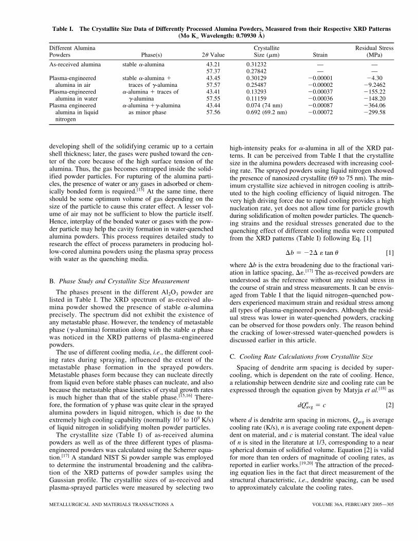
Fig. 12—Bright-field TEM image of as-received alumina powder particle.
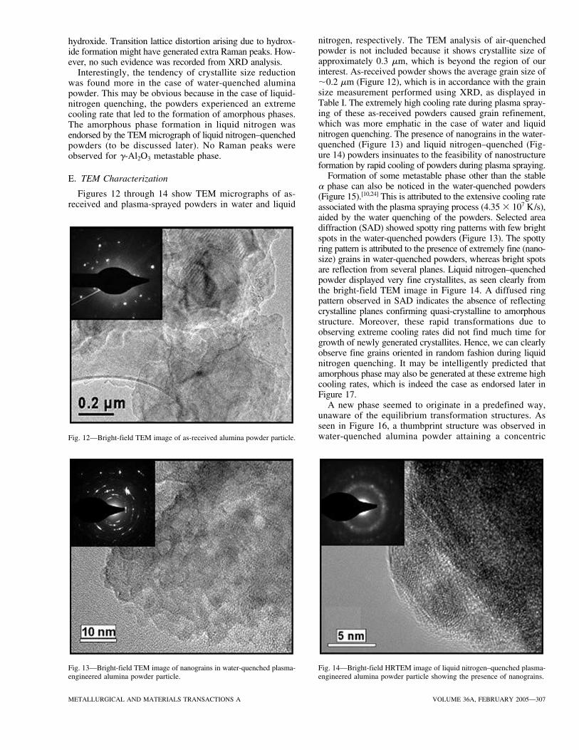
Fig. 13—Bright-field TEM image of nanograins in water-quenched plasma-engineered alumina powder particle.
hydroxide. Transition lattice distortion arising due to hydrox-ide formation might have generated extra Raman peaks. How-ever, no such evidence was recorded from XRD analysis.
Interestingly, the tendency of crystallite size reductionwas found more in the case of water-quenched aluminapowder. This may be obvious because in the case of liquid-nitrogen quenching, the powders experienced an extremecooling rate that led to the formation of amorphous phases.The amorphous phase formation in liquid nitrogen wasendorsed by the TEM micrograph of liquid nitrogen–quenchedpowders (to be discussed later). No Raman peaks wereobserved for �-Al2O3 metastable phase.
E. TEM Characterization
Figures 12 through 14 show TEM micrographs of as-received and plasma-sprayed powders in water and liquid
Fig. 14—Bright-field HRTEM image of liquid nitrogen–quenched plasma-engineered alumina powder particle showing the presence of nanograins.
nitrogen, respectively. The TEM analysis of air-quenchedpowder is not included because it shows crystallite size ofapproximately 0.3 �m, which is beyond the region of ourinterest. As-received powder shows the average grain size of�0.2 �m (Figure 12), which is in accordance with the grainsize measurement performed using XRD, as displayed inTable I. The extremely high cooling rate during plasma spray-ing of these as-received powders caused grain refinement,which was more emphatic in the case of water and liquidnitrogen quenching. The presence of nanograins in the water-quenched (Figure 13) and liquid nitrogen–quenched (Fig-ure 14) powders insinuates to the feasibility of nanostructureformation by rapid cooling of powders during plasma spraying.
Formation of some metastable phase other than the stable� phase can also be noticed in the water-quenched powders(Figure 15).[10,24] This is attributed to the extensive cooling rateassociated with the plasma spraying process (4.35 � 107 K/s),aided by the water quenching of the powders. Selected areadiffraction (SAD) showed spotty ring patterns with few brightspots in the water-quenched powders (Figure 13). The spottyring pattern is attributed to the presence of extremely fine (nano-size) grains in water-quenched powders, whereas bright spotsare reflection from several planes. Liquid nitrogen–quenchedpowder displayed very fine crystallites, as seen clearly fromthe bright-field TEM image in Figure 14. A diffused ringpattern observed in SAD indicates the absence of reflectingcrystalline planes confirming quasi-crystalline to amorphousstructure. Moreover, these rapid transformations due toobserving extreme cooling rates did not find much time forgrowth of newly generated crystallites. Hence, we can clearlyobserve fine grains oriented in random fashion during liquidnitrogen quenching. It may be intelligently predicted thatamorphous phase may also be generated at these extreme highcooling rates, which is indeed the case as endorsed later inFigure 17.
A new phase seemed to originate in a predefined way,unaware of the equilibrium transformation structures. Asseen in Figure 16, a thumbprint structure was observed inwater-quenched alumina powder attaining a concentric

308—VOLUME 36A, FEBRUARY 2005 METALLURGICAL AND MATERIALS TRANSACTIONS A
Fig. 17—Bright-field TEM image showing formation of amorphous phasein liquid nitrogen– quenched plasma-engineered alumina powder particle.
Fig. 16—HRTEM bright-field image of water-quenched, plasma-engineeredpowder, showing the concentric growth of lattice fringes.
symmetry. We can clearly observe lattices merging into oneanother forming an aligning structure. This implies that nucle-ation has occurred at the center of the rings and then pro-ceeded further. With no particular direction of lattice fringes,the thumbprint structure is observed for high cooling ratesat specific regions. Metastable phase generation is accou-tered with rapid transformation kinetics, since shorter timesare available for the rearrangement of atoms in the crystallattice. Therefore, concentric fringes beautifully detail theformation of fine crystallites of new phase growing at theinterface between the already nucleated metastable phase
and the transforming surrounding structure. Rapid coolingresults in the characteristic cubic structure with aluminumtrapped in tetrahedral sites of the oxygen fcc lattice.[10] Hence,it may be proposed that insufficient time for alignment ofthe lattice fringes therefore may be leading to thumbprintand random orientation of the �-Al2O3 structure in water-and liquid-quenched conditions, respectively. Moreover, itmay be expected that the thumbprint structure will helpreduce the higher surface energy. This is reasoned sincethe growth of the new phase in constrained time (due tosevere quenching) will occur easily at the interface, as weobserve in Figure 16, through alignment of merging latticefringes. This indicates the compliance of the new phase struc-ture in accordance with the available duration of latticerealignment. The system can be looked upon as a transfor-mation under isothermal conditions, since the 99 pct trans-formations could complete in time as low as 5 times thoseof 1 pct transformation.[25] This is indicative of the require-ment of quick and sudden changes to transformed structure.
Activation energy of 4.5 eV for amorphous to �-Al2O3
phase transformation and an activation energy of 5.2 eVfor �-Al2O3 to �-Al2O3 phase transformation was observedby Igor and Brandon.[10] Therefore, we clearly say that �-Al2O3 to �-Al2O3 phase transformation requires more energywhen compared to amorphous to �-Al2O3 phase transfor-mation. Thereby, cooling rates observed by the spray parti-cles determine the new phase formation upon solidification.Moreover, amorphous phase formations require a steep tem-perature gradient and extreme cooling rates, which are antic-ipated in plasma spray processes as the extreme degree ofquenching is provided by liquid nitrogen.
Figure 17 confirms the formation of the amorphous phasein liquid nitrogen–quenched powders due to the extremecooling rate on the order of 2.27 � 108 K/s. Transforma-tion to �-Al2O3 requires rearrangement of the oxygen sub-
Fig. 15—Bright-field TEM image showing nucleation of a nanosize needle-shaped phase in water-quenched, plasma-engineered alumina powder particle.

METALLURGICAL AND MATERIALS TRANSACTIONS A VOLUME 36A, FEBRUARY 2005—309
lattice, but the lack of sufficient time for the rearrangementleaves the structure amorphous in the case of liquid nitro-gen quenching. Glassy structure signifying the formationof a diffused ring pattern was also confirmed through theTEM selected area electron diffraction pattern.
IV. CONCLUSIONS
Plasma spray atomization successfully attained spher-oidization of alumina ceramic powder particles under dif-ferent quenching media. Water-and liquid nitrogen–quenchedpowders achieved refined nanostructured morphology withincreasing cooling rates of quenching media. Further researchpotential lies in controlling the characteristics of sprayedalumina ceramic powders controlling hollow-core particlesin water-quenched plasma-sprayed powders. Nanostructureformation in the liquid nitrogen–quenched plasma-sprayedpowders was confirmed with grain-size measurements usingthe diffraction peaks. The cooling rates of the processedpowders were calculated in the range of 3.33 � 106 to 2.27� 108 K/s for plasma-sprayed powders quenched in differ-ent media. The TEM studies of the water-and liquid nitro-gen–quenched plasma-engineered powders corroborate thepresence of nanostructure, metastable phase, and amorphousphase formation in the powders. Extensive TEM studies des-ignated lattice fringes as germination of fine crystallites withincreasing severity of quench.
ACKNOWLEDGMENT
The authors thank Professors S. Saxena and W.K. Jones,Department of Mechanical and Materials Engineering, FloridaInternational University, for carrying out the XRD studiesand the analysis of data in their laboratory facilities. Theauthors acknowledge the financial support from the FloridaInternational University Foundation for performing this work.The authors also appreciate Plasma Processes Inc. (Huntsville,AL), where the powder synthesis was performed by plasmaspraying route.
REFERENCES1. C. Suryanarayana: JOM, 2002, vol. 54 (9), pp. 24-27.2. L.L. Shaw, D. Goberman, R. Ren, M. Gell, S. Jiang, Y. Wang, T.D.
Xiao, and P.R. Strutt: Surf. Coating Technol., 2000, vol. 130, pp. 1-8.3. R.S. Lima, A. Kucuk, U. Senturk, and C.C. Berndt: J. Th. Sp. Technol.,
2001, vol. 10 (1), pp. 179-80.4. Arvind Agarwal, Tim McKechnie, and S. Seal: J. Th. Sp. Technol.,
2003, vol. 12 (3), pp. 350-59.5. S. Seal. S.C. Kuiry, P. Georgieva, and A. Agarwal: MRS Bull., 2004,
vol. 29 (1), pp. 16-21.6. J. He, M. Ice, J.M. Schoenung, D.H. Shin, and E.J. Lavernia: J. Th.
Sp. Technol., 2001, vol. 10 (2), pp. 293-300.7. P.V. Ananthapadmanabhan, K.P. Sreekumar, N. Venkatramani,
R. Kameswaran, C.C. Dias, and S.C. Mishra: Mater. Sci. Bull., 1996,vol. 19 (3), pp. 559-64.
8. K.A. Khor: J. Mater. Proc. Technol., 1992 vol. 29, pp. 267-81.9. M. Entezarian, F. Allaire, P. Tsantrizos, and R.A.L. Drew: J. Met.,
1996, pp. 53-55.10. Igor Levin and David Brandon: J. Am. Ceram. Soc., 1998, vol. 81 (8),
pp. 1995-2012.11. M. Chatterjee, D. Enkhtuvshin, B. Siladitya, and D. Ganguli: J. Mater.
Sci., 1998, vol. 33, pp. 4937-42.12. W.A. Johnson, N.E. Kopatz, and E.B. Yoder: Proc. on Progress in
Powder Metallurgy, Metal Powder Industries Federation, Boston, MA,1986, vol. 42, pp. 775-89.
13. K.H. Stern: Metallurgical and Ceramic Protective Coatings, Chapman& Hall, London, 1996, pp. 261-89.
14. S. Lee and G. Ravichandran: Opt. Lasers Eng., 2003, vol. 40, pp. 341-52.
15. C.L. Tien: Ann. Rev. Heat Transfer, 2000, vol. 11, pp. 207-305.16. K.N. Ishihara: in Non-Equilibrium Processing of Materials, C.
Suryanarayana, ed., Pergamon Press, Oxford, UK, 1999, pp. 5-20.17. B.D. Cullity: Elements of X-Ray Diffraction, 2nd ed., Addison-Wesley
Publishing Co., Inc., Reading, MA, 1978, pp. 102-286.18. H. Matyja, B.C. Giessen, and N.J. Grant: J. Inst. Met., 1968, vol. 96,
pp. 30-32.19. S. Sampath and H. Herman: J. Sp. Technol., 1996, vol. 5 (4), pp. 445-56.20. T.W. Simpson, Q. Wen, N. Yu, and D.R. Clarke: J. Am. Soc., 1998,
vol. 81 (1), pp. 61-66.21. R. Krishnan, R. Kesavamoorthy, S. Dash, A.K. Tyagi, and Baldev Raj:
Scripta Mater., 2003, vol. 48, pp. 1099-1104.22. P.V. Thomas, V. Ramakrishnan, and V.K. Vaidyan: Thin Solid Films,
1989, vol. 170, pp. 35-40.23. Charles P. Poole, Jr. and Frank J. Owens: Introduction to Nanotech-
nology, John Wiley & Sons, Inc., New York, NY, 2003 pp. 194-227.24. H.D. Ruan, R.L. Frost, and J.T. Kloprogge: J. Raman Spectr., 2001,
vol. 32, pp. 745-50.25. K. C. Russell, F. H. Froes: Mater. Sci. Eng. B, 1995, vol. 32, pp. 279-84.