synthesis of g-c3n4/bi2o3/tio2 composite nanotubes...
TRANSCRIPT
RSC Advances
PAPER
Publ
ishe
d on
26
May
201
5. D
ownl
oade
d by
Cal
ifor
nia
Inst
itute
of
Tec
hnol
ogy
on 1
9/06
/201
5 23
:16:
59.
View Article OnlineView Journal | View Issue
Synthesis of g-C
aSchool of Environmental Science and Engi
Hangzhou 310018, China. E-mail: zhangy
Tel: +86-571-28878218bLinde-Robinson Laboratories, California
91125, USA
† Electronic supplementary informa10.1039/c5ra02750k
Cite this: RSC Adv., 2015, 5, 48983
Received 12th February 2015Accepted 26th May 2015
DOI: 10.1039/c5ra02750k
www.rsc.org/advances
This journal is © The Royal Society of C
3N4/Bi2O3/TiO2 compositenanotubes: enhanced activity under visible lightirradiation and improved photoelectrochemicalactivity†
Yi Zhang,*ab Jiani Lu,a Michael R. Hoffmann,b Qiang Wang,a Yanqing Cong,a Qi Wanga
and Huan Jina
g-C3N4 and Bi2O3 were successfully incorporated into TiO2 nanotubes (TiO2-NT) to produce a composite
nanotubematerial designated as g-C3N4/Bi2O3/TiO2. The photoelectrochemical (PEC) activity under visible
light irradiation with respect to bleaching of methylene blue (MB) and degradation of phenol were
determined. The UV-vis absorption spectrum of the composite material, g-C3N4/Bi2O3/TiO2-NT, was
red-shifted toward a narrower band gap energy (Eg). The valence band (VB) of g-C3N4/Bi2O3/TiO2-NT
was shifted to a more positive potential resulting in an increased driving force for water oxidation. The
photocurrent generated by g-C3N4/Bi2O3/TiO2-NTs was approximately 15 times higher and the incident
photon-to-current efficiency (IPCE at l ¼ 400 nm) was higher than that of the naked TiO2-NTs. This
response is attributed to increasing the lifetimes of photo-generated electron–hole pairs. A significantly
higher PEC response in terms of the bleaching of MB was observed on g-C3N4/Bi2O3/TiO2-NT. The roles
of improved charge separation and subsequent higher electron-transfer efficiencies for in g-C3N4/Bi2O3/
TiO2-NT electrodes were examined.
1. Introduction
Semiconductor photocatalysis has been extensively explored fora variety of environmental control applications1–3 and for solarenergy conversion in terms of photocatalytic water-splitting4,5
and articial photosynthesis including CO2 reduction tohydrocarbon fuels.6 Photoelectrochemical (PEC) activity underan applied potential bias was applied for splitting water ordegradation of environmental pollutants. Since 43% ofincoming solar radiation is within the visible region, improvingsolar conversion efficiency over this region is important.7 Forlarge-scale applications, sustained and in-depth attention hasbeen paid to TiO2 because the cost is low, stability is excellentand band edge potential is suitable.8,9 However, since UV light(4% of the solar spectrum) at l# 385 nm is required to activateanatase TiO2, the potential practical applications are limited.10
The modied TiO2 has been investigated to improve the pho-tocatalytic activity induced by visible light. For instance, dopingTiO2 with metal ions11,12 or nonmetal ions13,14 have been
neering, Zhejiang Gongshang University,
[email protected]; Fax: +86-571-28008215;
Institute of Technology, Pasadena, CA
tion (ESI) available. See DOI:
hemistry 2015
employed. Moreover, some non-oxide photocatalysts (e.g., metalsuldes, (oxy) nitrides and oxysuldes)15,16 and various metalcomplexes (e.g., Pt, Au or Ag)17 are quite active under visiblelight irradiation. However, rapid electron–hole recombination,reduced stability, and high costs of production of the dopedmetal oxides prevent their larger-scale practical applications.
Recently, compositing with two or more different substancestogether on TiO2 has drawn increasing attention to researchersand been conrmed to be an effective approach. Polypyrrole-decorated Ag–TiO2 nanobers,18 Bi2O3/Bi4Ti3O12/TiO2 nano-belts,19 Bi2O3/TiO2/graphene composite systems20 have shownpromise for achieving higher visible light photocatalyticactivity. In addition, electrochemistry improving the photo-catalysis system also has been developed. N and S co-doped intoTiO2 nanotube array lms21 and B and P co-doped TiO2 nano-tube arrays22 exhibited excellent PEC properties and photo-catalytic activities than undoped TiO2.
Recently, graphitic carbon nitride (g-C3N4) was studiedhaving capable of oxidation of pollutants under visible lightirradiation.23,24 Moreover, g-C3N4 has high chemical andthermal stability with narrower band gap energy (Eg) of 2.7 eV(ref. 23) than TiO2. Other researchers have synthesized TiO2
modied with g-C3N4 by chemical vapor deposition25 or elec-trodeposition methods26 to obtain materials that were photo-electrocatalytically active under visible light illumination. Bi2O3
is also being explored as a potentially useful photocatalyst due
RSC Adv., 2015, 5, 48983–48991 | 48983
RSC Advances Paper
Publ
ishe
d on
26
May
201
5. D
ownl
oade
d by
Cal
ifor
nia
Inst
itute
of
Tec
hnol
ogy
on 1
9/06
/201
5 23
:16:
59.
View Article Online
to its lower bandgap energy (2.8 eV) and benecial electricalproperties.27 Bi2O3 has also been combined with TiO2 forimproved visible light activity.28,29 A multi-material compositeincorporating g-C3N4 and Bi2O3 into titanium dioxide nano-tubes was prepared and tested in our paper attempting toimprove both the photocatalytic and photoelectrochemicalactivities under visible light irradiation.
Modication of TiO2 nanotubes (TiO2-NT) via incorporationof g-C3N4 and Bi2O3 is expected to improve the overall visiblelight activity when compared to naked TiO2. Compared to theVB edge of TiO2 (2.7 V vs. NHE (pH ¼ 7)),30 the band edge ofg-C3N4 is more negative (1.4 V vs. NHE (pH ¼ 7)),30 while theband edge of Bi2O3 is more positive (3.13 V vs. NHE (pH ¼ 7)).31
This combination should improve overall electron–hole sepa-ration and improve electron transfer characteristics.
In order to prepare the composite catalyst, we employed athermal poly-condensation and dip-coating method to modifyTiO2-NTs with g-C3N4 and Bi2O3. The degradation of methyleneblue (MB) and phenol by PEC performance was investigatedusing a composite catalyst as anode. The PEC performances ofthe composite electrodes were examined and the photocatalytic(PC) and electrocatalytic (EC) activities under identical reactionconditions were also compared. A mechanism to account forenhanced PEC activity was nally proposed.
2. Experimental methods2.1. Chemical reagents
Oxalic acid dehydrate ((COOH)2$2H2O) ($99.5% purity),ammonium uoride (NH4F) ($96.0% purity), melamine(C3H6N6) ($98.5% purity), bismuth nitrate pentahydrate(Bi(NO3)3$5H2O) ($99.0% purity), methyl alcohol (CH3OH)($99.9% purity, HPLC, TEDIA company), ethylene glycol(C2H6O2) ($99.5% purity), sodium sulfate (Na2SO4) ($99.0%purity), sodium sulte (Na2SO3) ($97.0% purity) were allpurchased from Hangzhou Huipu Chemical Reagent Co., Ltd.
2.2. Synthesis of g-C3N4/Bi2O3/TiO2 nanotubes
Electrochemical anodization method was used to prepare TiO2-NTs electrodes. The Ti sheet (0.5 mm thick, 99.5% purity) waswashed by ultrasonic irradiation for 15 min. The electro-chemical reaction was operated using Ti sheet as anode and Nisheet as cathode with the voltage of 20 V for 120 min. Theelectrolyte was a mixed solution of 1/12 M (COOH)2$2H2O and0.5 wt% NH4F.32,33 Metal-free g-C3N4 powders were prepared bycalcination of melamine to 520 �C for 4 h.34
The g-C3N4/Bi2O3/TiO2-NTs composites were prepared by adip-coating method in which 0.2 g g-C3N4 and 0.243 gBi(NO3)3$5H2O were dispersed in 20 mL of ethylene glycolsolution; the TiO2-NTs that were still attached to the Ti sheetwere slowly dipped up and down from the above solution for30 min. The dipped coated sheets were then annealed at400 �C for 2 h.33 When g-C3N4/TiO2-NTs or Bi2O3/TiO2-NTswere prepared, the precursor solution was changed to 0.2 gg-C3N4 or 0.243 g Bi(NO3)3$5H2O in 20 mL of ethylene glycolsolution.
48984 | RSC Adv., 2015, 5, 48983–48991
2.3. Characterization of the synthesized g-C3N4/Bi2O3/TiO2
nanotubes
The synthesized materials (TiO2-NTs, g-C3N4/TiO2-NTs, Bi2O3/TiO2-NTs and g-C3N4/Bi2O3/TiO2-NTs) were characterized byX-ray diffractometer (XRD), X-ray photoelectron spectroscope(XPS), emission scanning electron microscope (FE-SEM, HitachiS-4700 II) with an energy-dispersive X-ray spectrometer (EDX),transmission electron microscope (TEM) and UV-vis diffusereectance spectra (DRS).
2.4. PEC experimental techniques
The PEC properties of each sample were determined using anelectrochemical workstation (CHI 660D). Modied TiO2-NTselectrodes were used as working electrodes with saturated Ag/AgCl electrode as a reference electrode and Pt sheet as acounter electrode, respectively. Visible light at an intensity of100 mW cm�2 was obtained by using a Xe-lamp light sourcewith UV lter (l > 420 nm). Photocurrents and incident-photon-to-current efficiencies (IPCE) were tested in mixed 0.1 M Na2SO4
and Na2SO3 solutions at pH of 10.5. IPCE measurements weretaken at the visible wavelengths of 400, 430, 450, 475, 500, 550,600 and 633 nm with a light intensity meter (model FZ-A). Mott–Schottky (M–S) plots and Nyquist plots were taken in 0.1 MNa2SO4 solutions at pH ¼ 7.6. M–S plots were obtained atfrequencies of 500, 1000 and 3000 Hz at an AC amplitude of 5mV. Nyquist plots were obtained both under dark and visiblelight conditions. The experiments including Nyquist plots, LSVsand IPCE plots were repeated for 3 times.
The activity of the prepared catalyst was assessed in threedifferent modes of operation that include (1) photocatalytic(PC), (2) electrocatalytic (EC) and photoelectrocatalytic (PEC).The applied potential in EC and PEC process was 3.0 V. In eachcase, an electrolyte solution consisting of 0.1 M Na2SO4 wasirradiated with visible light that had an average light intensity of200 mW cm�2. MB (100 mL, 1� 10�5 M, without regulating pH)and phenol (100 mL, 10 mg L�1, pH ¼ 3) tted with an activeelectrode with a 4.5 cm2 effective surface area of g-C3N4/Bi2O3/TiO2-NTs. Before initiating the reactions under illumination,the solution reacted with catalyst electrode for 30 min withoutlight. At given time intervals, 3 mL MB and 1 mL phenol aliquotsamples were collected. The variation in the MB concentrationswas recorded using an UV-vis spectrophotometer. The concen-trations of phenol were analyzed by HPLC with a Diamonsil C18column and ultraviolet detection at 278 nm with ratio of thedeionized water and methanol of 6 : 4 (v/v) and a ow rate of 1.0mL min�1. The overall MB bleaching process and phenoldegradation was tted to pseudo rst-order kinetics.
3. Results and discussion3.1. SEM and TEM analyses
Fig. 1 shows the morphologies of TiO2-NTs, g-C3N4/TiO2-NTs,Bi2O3/TiO2-NTs, g-C3N4/Bi2O3/TiO2-NTs, and pure g-C3N4. TheTiO2-NTs electrode has almost uniform holes and a highlyordered tubular structure. The average of the inner diameter ofTiO2-NTs is close to 80 nm, and their average of outer diameter
This journal is © The Royal Society of Chemistry 2015
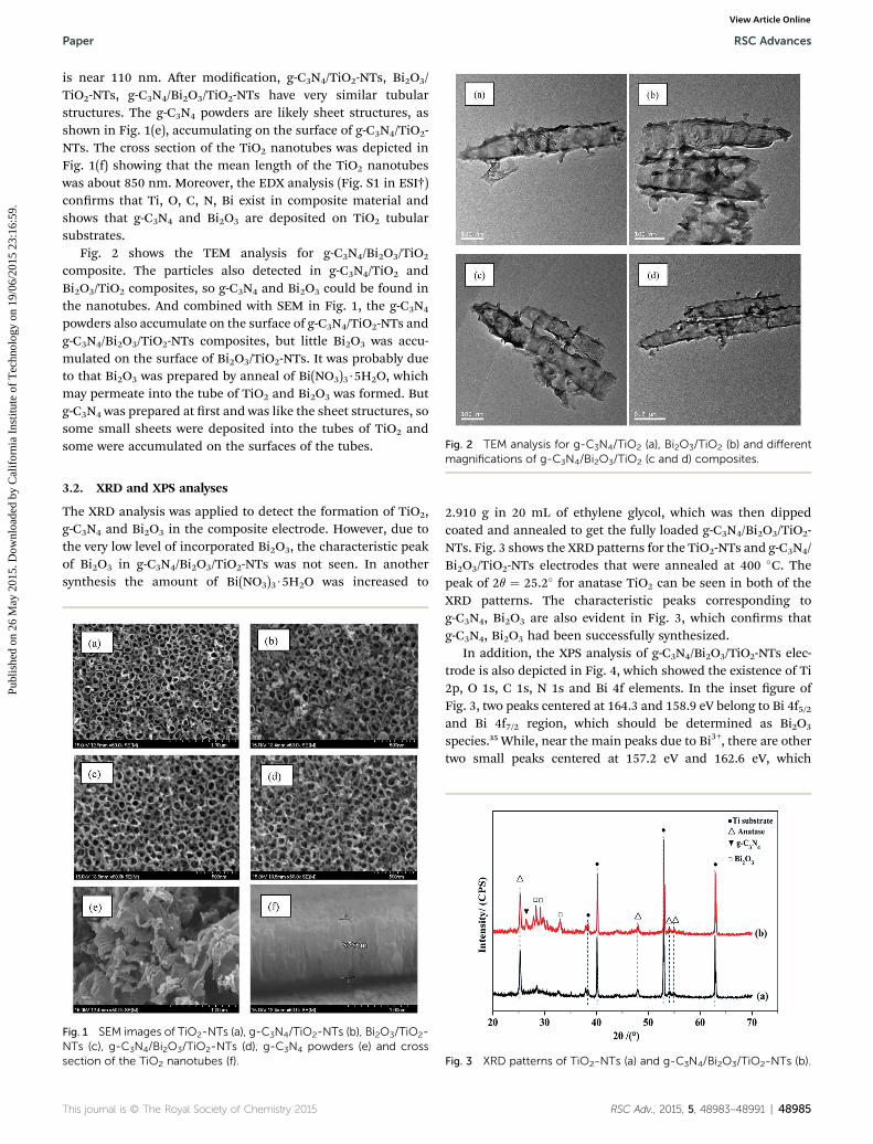
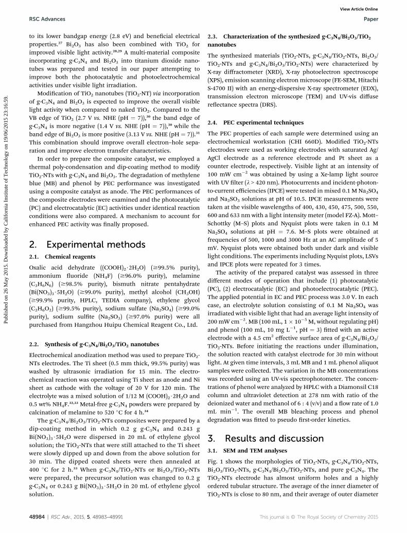
Fig. 2 TEM analysis for g-C3N4/TiO2 (a), Bi2O3/TiO2 (b) and different
Paper RSC Advances
Publ
ishe
d on
26
May
201
5. D
ownl
oade
d by
Cal
ifor
nia
Inst
itute
of
Tec
hnol
ogy
on 1
9/06
/201
5 23
:16:
59.
View Article Online
is near 110 nm. Aer modication, g-C3N4/TiO2-NTs, Bi2O3/TiO2-NTs, g-C3N4/Bi2O3/TiO2-NTs have very similar tubularstructures. The g-C3N4 powders are likely sheet structures, asshown in Fig. 1(e), accumulating on the surface of g-C3N4/TiO2-NTs. The cross section of the TiO2 nanotubes was depicted inFig. 1(f) showing that the mean length of the TiO2 nanotubeswas about 850 nm. Moreover, the EDX analysis (Fig. S1 in ESI†)conrms that Ti, O, C, N, Bi exist in composite material andshows that g-C3N4 and Bi2O3 are deposited on TiO2 tubularsubstrates.
Fig. 2 shows the TEM analysis for g-C3N4/Bi2O3/TiO2
composite. The particles also detected in g-C3N4/TiO2 andBi2O3/TiO2 composites, so g-C3N4 and Bi2O3 could be found inthe nanotubes. And combined with SEM in Fig. 1, the g-C3N4
powders also accumulate on the surface of g-C3N4/TiO2-NTs andg-C3N4/Bi2O3/TiO2-NTs composites, but little Bi2O3 was accu-mulated on the surface of Bi2O3/TiO2-NTs. It was probably dueto that Bi2O3 was prepared by anneal of Bi(NO3)3$5H2O, whichmay permeate into the tube of TiO2 and Bi2O3 was formed. Butg-C3N4 was prepared at rst and was like the sheet structures, sosome small sheets were deposited into the tubes of TiO2 andsome were accumulated on the surfaces of the tubes.
magnifications of g-C3N4/Bi2O3/TiO2 (c and d) composites.
3.2. XRD and XPS analyses
The XRD analysis was applied to detect the formation of TiO2,g-C3N4 and Bi2O3 in the composite electrode. However, due tothe very low level of incorporated Bi2O3, the characteristic peakof Bi2O3 in g-C3N4/Bi2O3/TiO2-NTs was not seen. In anothersynthesis the amount of Bi(NO3)3$5H2O was increased to
Fig. 1 SEM images of TiO2-NTs (a), g-C3N4/TiO2-NTs (b), Bi2O3/TiO2-NTs (c), g-C3N4/Bi2O3/TiO2-NTs (d), g-C3N4 powders (e) and crosssection of the TiO2 nanotubes (f).
This journal is © The Royal Society of Chemistry 2015
2.910 g in 20 mL of ethylene glycol, which was then dippedcoated and annealed to get the fully loaded g-C3N4/Bi2O3/TiO2-NTs. Fig. 3 shows the XRD patterns for the TiO2-NTs and g-C3N4/Bi2O3/TiO2-NTs electrodes that were annealed at 400 �C. Thepeak of 2q ¼ 25.2� for anatase TiO2 can be seen in both of theXRD patterns. The characteristic peaks corresponding tog-C3N4, Bi2O3 are also evident in Fig. 3, which conrms thatg-C3N4, Bi2O3 had been successfully synthesized.
In addition, the XPS analysis of g-C3N4/Bi2O3/TiO2-NTs elec-trode is also depicted in Fig. 4, which showed the existence of Ti2p, O 1s, C 1s, N 1s and Bi 4f elements. In the inset gure ofFig. 3, two peaks centered at 164.3 and 158.9 eV belong to Bi 4f5/2and Bi 4f7/2 region, which should be determined as Bi2O3
species.35 While, near the main peaks due to Bi3+, there are othertwo small peaks centered at 157.2 eV and 162.6 eV, which
Fig. 3 XRD patterns of TiO2-NTs (a) and g-C3N4/Bi2O3/TiO2-NTs (b).
RSC Adv., 2015, 5, 48983–48991 | 48985
RSC Advances Paper
Publ
ishe
d on
26
May
201
5. D
ownl
oade
d by
Cal
ifor
nia
Inst
itute
of
Tec
hnol
ogy
on 1
9/06
/201
5 23
:16:
59.
View Article Online
probably belong to reduced Bi oxidation phase or Bi0.36,37 Basedon several studies about the reduced Bi phase, it could interactwith the structure of Bi oxidation and titania to form the elec-tronic effect between these two oxides.36,38
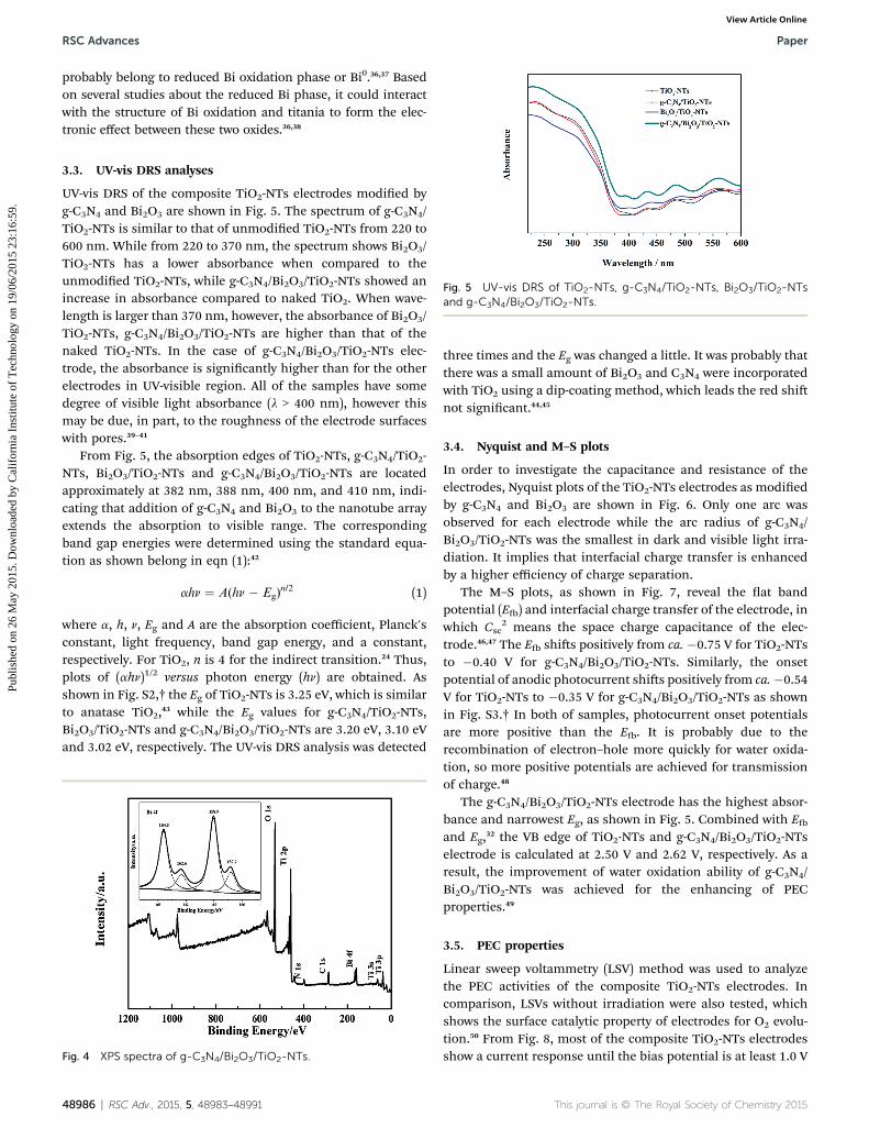
Fig. 5 UV-vis DRS of TiO2-NTs, g-C3N4/TiO2-NTs, Bi2O3/TiO2-NTsand g-C3N4/Bi2O3/TiO2-NTs.
3.3. UV-vis DRS analyses
UV-vis DRS of the composite TiO2-NTs electrodes modied byg-C3N4 and Bi2O3 are shown in Fig. 5. The spectrum of g-C3N4/TiO2-NTs is similar to that of unmodied TiO2-NTs from 220 to600 nm. While from 220 to 370 nm, the spectrum shows Bi2O3/TiO2-NTs has a lower absorbance when compared to theunmodied TiO2-NTs, while g-C3N4/Bi2O3/TiO2-NTs showed anincrease in absorbance compared to naked TiO2. When wave-length is larger than 370 nm, however, the absorbance of Bi2O3/TiO2-NTs, g-C3N4/Bi2O3/TiO2-NTs are higher than that of thenaked TiO2-NTs. In the case of g-C3N4/Bi2O3/TiO2-NTs elec-trode, the absorbance is signicantly higher than for the otherelectrodes in UV-visible region. All of the samples have somedegree of visible light absorbance (l > 400 nm), however thismay be due, in part, to the roughness of the electrode surfaceswith pores.39–41
From Fig. 5, the absorption edges of TiO2-NTs, g-C3N4/TiO2-NTs, Bi2O3/TiO2-NTs and g-C3N4/Bi2O3/TiO2-NTs are locatedapproximately at 382 nm, 388 nm, 400 nm, and 410 nm, indi-cating that addition of g-C3N4 and Bi2O3 to the nanotube arrayextends the absorption to visible range. The correspondingband gap energies were determined using the standard equa-tion as shown belong in eqn (1):42
ahn ¼ A(hn � Eg)n/2 (1)
where a, h, n, Eg and A are the absorption coefficient, Planck'sconstant, light frequency, band gap energy, and a constant,respectively. For TiO2, n is 4 for the indirect transition.24 Thus,plots of (ahn)1/2 versus photon energy (hn) are obtained. Asshown in Fig. S2,† the Eg of TiO2-NTs is 3.25 eV, which is similarto anatase TiO2,43 while the Eg values for g-C3N4/TiO2-NTs,Bi2O3/TiO2-NTs and g-C3N4/Bi2O3/TiO2-NTs are 3.20 eV, 3.10 eVand 3.02 eV, respectively. The UV-vis DRS analysis was detected
Fig. 4 XPS spectra of g-C3N4/Bi2O3/TiO2-NTs.
48986 | RSC Adv., 2015, 5, 48983–48991
three times and the Eg was changed a little. It was probably thatthere was a small amount of Bi2O3 and C3N4 were incorporatedwith TiO2 using a dip-coating method, which leads the red shinot signicant.44,45
3.4. Nyquist and M–S plots
In order to investigate the capacitance and resistance of theelectrodes, Nyquist plots of the TiO2-NTs electrodes as modiedby g-C3N4 and Bi2O3 are shown in Fig. 6. Only one arc wasobserved for each electrode while the arc radius of g-C3N4/Bi2O3/TiO2-NTs was the smallest in dark and visible light irra-diation. It implies that interfacial charge transfer is enhancedby a higher efficiency of charge separation.
The M–S plots, as shown in Fig. 7, reveal the at bandpotential (E) and interfacial charge transfer of the electrode, inwhich Csc
2 means the space charge capacitance of the elec-trode.46,47 The E shis positively from ca. �0.75 V for TiO2-NTsto �0.40 V for g-C3N4/Bi2O3/TiO2-NTs. Similarly, the onsetpotential of anodic photocurrent shis positively from ca.�0.54V for TiO2-NTs to �0.35 V for g-C3N4/Bi2O3/TiO2-NTs as shownin Fig. S3.† In both of samples, photocurrent onset potentialsare more positive than the E. It is probably due to therecombination of electron–hole more quickly for water oxida-tion, so more positive potentials are achieved for transmissionof charge.48
The g-C3N4/Bi2O3/TiO2-NTs electrode has the highest absor-bance and narrowest Eg, as shown in Fig. 5. Combined with Eand Eg,32 the VB edge of TiO2-NTs and g-C3N4/Bi2O3/TiO2-NTselectrode is calculated at 2.50 V and 2.62 V, respectively. As aresult, the improvement of water oxidation ability of g-C3N4/Bi2O3/TiO2-NTs was achieved for the enhancing of PECproperties.49
3.5. PEC properties
Linear sweep voltammetry (LSV) method was used to analyzethe PEC activities of the composite TiO2-NTs electrodes. Incomparison, LSVs without irradiation were also tested, whichshows the surface catalytic property of electrodes for O2 evolu-tion.50 From Fig. 8, most of the composite TiO2-NTs electrodesshow a current response until the bias potential is at least 1.0 V
This journal is © The Royal Society of Chemistry 2015
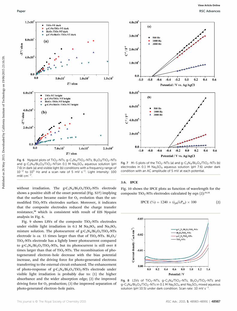
Fig. 6 Nyquist plots of TiO2-NTs, g-C3N4/TiO2-NTs, Bi2O3/TiO2-NTsand g-C3N4/Bi2O3/TiO2-NTsin 0.1 M Na2SO4 aqueous solution (pH7.6) in dark (a) and visible light (b) conditions with a frequency range of10�2 to 105 Hz and a scan rate of 5 mV s�1. Light intensity: 100mW cm�2.
Fig. 7 M–S plots of the TiO2-NTs (a) and g-C3N4/Bi2O3/TiO2-NTs (b)electrodes in 0.1 M Na2SO4 aqueous solution (pH 7.6) under darkcondition with an AC amplitude of 5 mV at each potential.
Fig. 8 LSVs of TiO2-NTs, g-C3N4/TiO2-NTs, Bi2O3/TiO2-NTs andg-C3N4/Bi2O3/TiO2-NTs in 0.1 M Na2SO4 and Na2SO3 mixed aqueoussolution (pH 10.5) under dark condition. Scan rate: 10 mV s�1.
Paper RSC Advances
Publ
ishe
d on
26
May
201
5. D
ownl
oade
d by
Cal
ifor
nia
Inst
itute
of
Tec
hnol
ogy
on 1
9/06
/201
5 23
:16:
59.
View Article Online
without irradiation. The g-C3N4/Bi2O3/TiO2-NTs electrodeshows a positive shi of the onset potential (Fig. S3†) implyingthat the surface became easier for O2 evolution than the un-modied TiO2-NTs electrodes surface. Moreover, it indicatesthat the composite electrodes reduced the charge transferresistance,50 which is consistent with result of EIS Nyquistanalysis in Fig. 6.
Fig. 9 shows LSVs of the composite TiO2-NTs electrodesunder visible light irradiation in 0.1 M Na2SO4 and Na2SO3
mixture solution. The photocurrent of g-C3N4/Bi2O3/TiO2-NTselectrode is ca. 15 times larger than that of TiO2-NTs. Bi2O3/TiO2-NTs electrode has a lightly lower photocurrent comparedto g-C3N4/Bi2O3/TiO2-NTs, but its photocurrent is still over 8times larger than that of TiO2-NTs. The recombination of pho-togenerated electron–hole decrease with the bias potentialincrease, and the driving force for photo-generated electronstransferring to the external circuit enhanced. The enhancementof photo-response of g-C3N4/Bi2O3/TiO2-NTs electrode undervisible light irradiation is probably due to: (1) the higherabsorbance and the wider absorption edge; (2) the improveddriving force for O2 production; (3) the improved separation ofphoto-generated electron–hole pairs.
This journal is © The Royal Society of Chemistry 2015
3.6. IPCE
Fig. 10 shows the IPCE plots as function of wavelength for thecomposite TiO2-NTs electrodes calculated by eqn (2):51,52
IPCE (%) ¼ 1240 � (iph/lPin) � 100 (2)
RSC Adv., 2015, 5, 48983–48991 | 48987
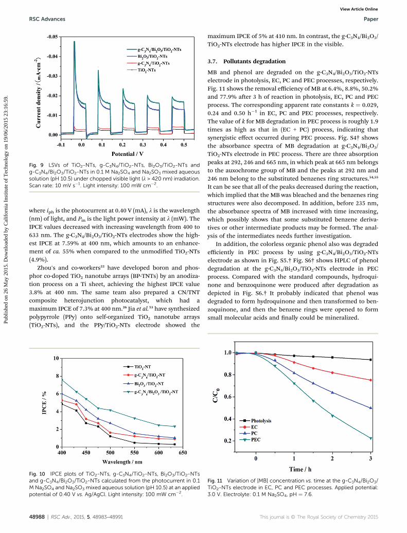
Fig. 9 LSVs of TiO2-NTs, g-C3N4/TiO2-NTs, Bi2O3/TiO2-NTs andg-C3N4/Bi2O3/TiO2-NTs in 0.1 M Na2SO4 and Na2SO3 mixed aqueoussolution (pH 10.5) under chopped visible light (l > 420 nm) irradiation.Scan rate: 10 mV s�1. Light intensity: 100 mW cm�2.
RSC Advances Paper
Publ
ishe
d on
26
May
201
5. D
ownl
oade
d by
Cal
ifor
nia
Inst
itute
of
Tec
hnol
ogy
on 1
9/06
/201
5 23
:16:
59.
View Article Online
where iph is the photocurrent at 0.40 V (mA), l is the wavelength(nm) of light, and Pin is the light power intensity at l (mW). TheIPCE values decreased with increasing wavelength from 400 to633 nm. The g-C3N4/Bi2O3/TiO2-NTs electrodes show the high-est IPCE at 7.59% at 400 nm, which amounts to an enhance-ment of ca. 55% when compared to the unmodied TiO2-NTs(4.9%).
Zhou's and co-workers22 have developed boron and phos-phor co-doped TiO2 nanotube arrays (BP-TNTs) by an anodiza-tion process on a Ti sheet, achieving the highest IPCE value3.8% at 400 nm. The same team also prepared a CN/TNTcomposite heterojunction photocatalyst, which had amaximum IPCE of 7.3% at 400 nm.26 Jia et al.53 have synthesizedpolypyrrole (PPy) onto self-organized TiO2 nanotube arrays(TiO2-NTs), and the PPy/TiO2-NTs electrode showed the
Fig. 10 IPCE plots of TiO2-NTs, g-C3N4/TiO2-NTs, Bi2O3/TiO2-NTsand g-C3N4/Bi2O3/TiO2-NTs calculated from the photocurrent in 0.1M Na2SO4 and Na2SO3 mixed aqueous solution (pH 10.5) at an appliedpotential of 0.40 V vs. Ag/AgCl. Light intensity: 100 mW cm�2.
48988 | RSC Adv., 2015, 5, 48983–48991
maximum IPCE of 5% at 410 nm. In contrast, the g-C3N4/Bi2O3/TiO2-NTs electrode has higher IPCE in the visible.
3.7. Pollutants degradation
MB and phenol are degraded on the g-C3N4/Bi2O3/TiO2-NTselectrode in photolysis, EC, PC and PEC processes, respectively.Fig. 11 shows the removal efficiency of MB at 6.4%, 8.8%, 50.2%and 77.9% aer 3 h of reaction in photolysis, EC, PC and PECprocess. The corresponding apparent rate constants k ¼ 0.029,0.24 and 0.50 h�1 in EC, PC and PEC processes, respectively.The value of k for MB degradation in PEC process is roughly 1.9times as high as that in (EC + PC) process, indicating thatsynergistic effect occurred during PEC process. Fig. S4† showsthe absorbance spectra of MB degradation at g-C3N4/Bi2O3/TiO2-NTs electrode in PEC process. There are three absorptionpeaks at 292, 246 and 665 nm, in which peak at 665 nm belongsto the auxochrome group of MB and the peaks at 292 nm and246 nm belong to the substituted benzenes ring structures.54,55
It can be see that all of the peaks decreased during the reaction,which implied that the MB was bleached and the benzenes ringstructures were also decomposed. In addition, before 235 nm,the absorbance spectra of MB increased with time increasing,which possibly shows that some substituted benzene deriva-tives or other intermediate products may be formed. The anal-ysis of the intermediates needs further investigation.
In addition, the colorless organic phenol also was degradedefficiently in PEC process by using g-C3N4/Bi2O3/TiO2-NTselectrode as shown in Fig. S5.† Fig. S6† shows HPLC of phenoldegradation at the g-C3N4/Bi2O3/TiO2-NTs electrode in PECprocess. Compared with the standard compounds, hydroqui-none and benzoquinone were produced aer degradation asdepicted in Fig. S6.† It probably indicated that phenol wasdegraded to form hydroquinone and then transformed to ben-zoquinone, and then the benzene rings were opened to formsmall molecular acids and nally could be mineralized.
Fig. 11 Variation of [MB] concentration vs. time at the g-C3N4/Bi2O3/TiO2-NTs electrode in EC, PC and PEC processes. Applied potential:3.0 V. Electrolyte: 0.1 M Na2SO4, pH ¼ 7.6.
This journal is © The Royal Society of Chemistry 2015
Paper RSC Advances
Publ
ishe
d on
26
May
201
5. D
ownl
oade
d by
Cal
ifor
nia
Inst
itute
of
Tec
hnol
ogy
on 1
9/06
/201
5 23
:16:
59.
View Article Online
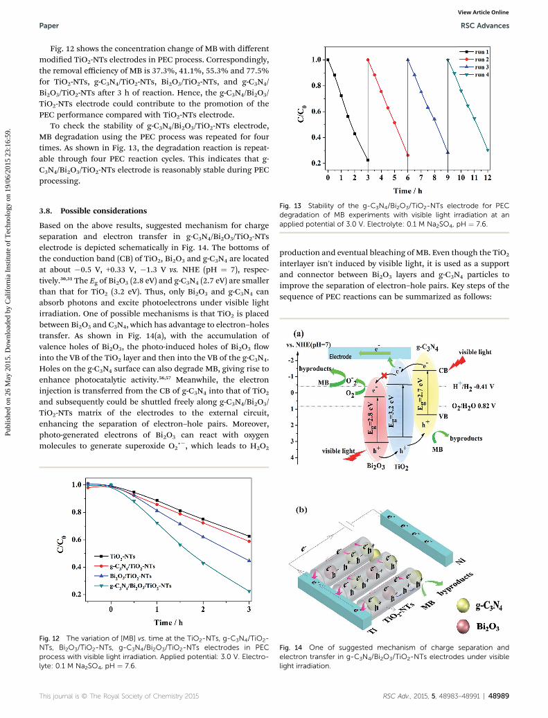
Fig. 12 shows the concentration change of MB with differentmodied TiO2-NTs electrodes in PEC process. Correspondingly,the removal efficiency of MB is 37.3%, 41.1%, 55.3% and 77.5%for TiO2-NTs, g-C3N4/TiO2-NTs, Bi2O3/TiO2-NTs, and g-C3N4/Bi2O3/TiO2-NTs aer 3 h of reaction. Hence, the g-C3N4/Bi2O3/TiO2-NTs electrode could contribute to the promotion of thePEC performance compared with TiO2-NTs electrode.
To check the stability of g-C3N4/Bi2O3/TiO2-NTs electrode,MB degradation using the PEC process was repeated for fourtimes. As shown in Fig. 13, the degradation reaction is repeat-able through four PEC reaction cycles. This indicates that g-C3N4/Bi2O3/TiO2-NTs electrode is reasonably stable during PECprocessing.
Fig. 13 Stability of the g-C3N4/Bi2O3/TiO2-NTs electrode for PECdegradation of MB experiments with visible light irradiation at anapplied potential of 3.0 V. Electrolyte: 0.1 M Na2SO4, pH ¼ 7.6.
3.8. Possible considerations
Based on the above results, suggested mechanism for chargeseparation and electron transfer in g-C3N4/Bi2O3/TiO2-NTselectrode is depicted schematically in Fig. 14. The bottoms ofthe conduction band (CB) of TiO2, Bi2O3 and g-C3N4 are locatedat about �0.5 V, +0.33 V, �1.3 V vs. NHE (pH ¼ 7), respec-tively.30,31 The Eg of Bi2O3 (2.8 eV) and g-C3N4 (2.7 eV) are smallerthan that for TiO2 (3.2 eV). Thus, only Bi2O3 and g-C3N4 canabsorb photons and excite photoelectrons under visible lightirradiation. One of possible mechanisms is that TiO2 is placedbetween Bi2O3 and C3N4, which has advantage to electron–holestransfer. As shown in Fig. 14(a), with the accumulation ofvalence holes of Bi2O3, the photo-induced holes of Bi2O3 owinto the VB of the TiO2 layer and then into the VB of the g-C3N4.Holes on the g-C3N4 surface can also degrade MB, giving rise toenhance photocatalytic activity.56,57 Meanwhile, the electroninjection is transferred from the CB of g-C3N4 into that of TiO2
and subsequently could be shuttled freely along g-C3N4/Bi2O3/TiO2-NTs matrix of the electrodes to the external circuit,enhancing the separation of electron–hole pairs. Moreover,photo-generated electrons of Bi2O3 can react with oxygenmolecules to generate superoxide O2c
�, which leads to H2O2
Fig. 12 The variation of [MB] vs. time at the TiO2-NTs, g-C3N4/TiO2-NTs, Bi2O3/TiO2-NTs, g-C3N4/Bi2O3/TiO2-NTs electrodes in PECprocess with visible light irradiation. Applied potential: 3.0 V. Electro-lyte: 0.1 M Na2SO4, pH ¼ 7.6.
This journal is © The Royal Society of Chemistry 2015
production and eventual bleaching of MB. Even though the TiO2
interlayer isn't induced by visible light, it is used as a supportand connector between Bi2O3 layers and g-C3N4 particles toimprove the separation of electron–hole pairs. Key steps of thesequence of PEC reactions can be summarized as follows:
Fig. 14 One of suggested mechanism of charge separation andelectron transfer in g-C3N4/Bi2O3/TiO2-NTs electrodes under visiblelight irradiation.
RSC Adv., 2015, 5, 48983–48991 | 48989

RSC Advances Paper
Publ
ishe
d on
26
May
201
5. D
ownl
oade
d by
Cal
ifor
nia
Inst
itute
of
Tec
hnol
ogy
on 1
9/06
/201
5 23
:16:
59.
View Article Online
Bi2O3 + hn / Bi2O3 (h+ + e�) (3)
g-C3N4 + hn / g-C3N4 (h+ + e�) (4)
Bi2O3 (h+) + TiO2 / TiO2 (h
+) + Bi2O3 (5)
TiO2 (h+) + g-C3N4 / g-C3N4 (h
+) + TiO2 (6)
g-C3N4 (e�) + TiO2 / TiO2 (e
�) + g-C3N4 (7)
TiO2 (e�) + bias voltage / TiO2 + external circuit (8)
Bi2O3 (e�) + O2 / Bi2O3 + O2c
� (9)
Of course, two of these three substances (TiO2, Bi2O3 andC3N4) composited together, the electron–holes also could betransferred from high energy band to low energy band. So someother phenomenon, such as electrons transferred from C3N4 toTiO2 or from TiO2 to C3N4, was described in Fig. 14(b).
4. Conclusion
g-C3N4 and Bi2O3 with TiO2-NTs have been coupled into acomposite photocatalytic and electrocatalytic material througha sequential dip-coating procedure followed by high-temperature annealing. Aer adding g-C3N4 and Bi2O3, in tothe host matrix, the absorption spectrum of g-C3N4/Bi2O3/TiO2-NTs electrode red-shied in to visible region of electromagneticspectrum, resulting in an increase in light absorbance.Compared to naked TiO2-NTs, photocurrent response of g-C3N4/Bi2O3/TiO2-NTs was enhanced by 15 times and PEC activity forpollutants degradation was also improved. The enhancement inthe PEC and IPCE activities was most likely due to the narrow-ing of the effective Eg coupled with a positive shi of E (ca. 0.35V). These results indicated that the g-C3N4/Bi2O3/TiO2-NTscomposite electrodes have the potential for wastewater treat-ment during PEC process under visible light irradiation.
Acknowledgements
This work was nancially supported by the National NaturalScience Foundation of China (no. 21276235, 21477114). Inaddition support was provided by the Educational Commissionof Zhejiang Province (Y201432049).
References
1 M. R. Hoffmann, S. T. Martin, W. Y. Choi andD. W. Bahnemann, Chem. Rev., 1995, 95, 69–96.
2 X. B. Chen, S. H. Shen, L. J. Guo and S. S. Mao, Chem. Rev.,2010, 110, 6503–6570.
3 H. Bao, F. F. Li, L. C. Lei, B. Yang and Z. J. Li, RSC Adv., 2014,4, 27277–27280.
4 A. J. Bard and M. A. Fox, Chem. Res., 1995, 28, 141–145.5 B. A. Pinaud, J. D. Benck, L. C. Seitz, A. J. Forman, Z. Chen,T. G. Deutsch, B. D. James, K. N. Baum, G. N. Baum,
48990 | RSC Adv., 2015, 5, 48983–48991
S. Ardo, H. L. Wang, E. Miller and T. F. Jaramillo, EnergyEnviron. Sci., 2013, 6, 1983–2002.
6 Q. Liu, D. Wu, Y. Zhou, H. B. Su, R. Wang, C. F. Zhang,S. C. Yan, M. Xiao and Z. G. Zou, ACS Appl. Mater.Interfaces, 2014, 6, 2356–2361.
7 Q. Li, B. D. Guo, J. G. Yu, J. R. Ran, B. H. Zhang, H. J. Yan andJ. R. Gong, J. Am. Chem. Soc., 2011, 133, 10878–10884.
8 G. Liu, L. Z. Wang, H. G. Yang, H. M. Cheng and G. Q. Lu, J.Mater. Chem., 2010, 20, 831–843.
9 F. E. Osterloh, Chem. Mater., 2008, 20, 35–54.10 X. B. Chen, L. Liu, P. Y. Yu and S. S. Mao, Science, 2011, 331,
746–750.11 H. Yamashita, M. Harada, J. Misaka, M. Takeuchi, K. Ikeue
and M. Anpo, J. Photochem. Photobiol. A: Chem., 2002, 148,257–261.
12 J. C. Yu, G. S. Li, X. C. Wang, X. L. Hu, C. W. Leung andZ. D. Zhang, Chem. Commun., 2006, 25, 2717–2719.
13 C. W. H. Dunnill, Z. A. Aiken, J. Pratten, M. Wilson,D. J. Morgan and I. P. Parkin, J. Photochem. Photobiol. A:Chem., 2009, 207, 244–253.
14 Y. X. Zhao, X. F. Qiu and C. Burda, Chem. Mater., 2008, 20,2629–2636.
15 Q. Kang, S. H. Liu, L. X. Yang, Q. Y. Cai and C. A. Grimes, ACSAppl. Mater. Interfaces, 2001, 3, 746–749.
16 K. Maeda and K. Domen, J. Phys. Chem. C, 2007, 111, 7851–7861.
17 K. Mogyorosi, A. Kmetyko, N. Czirbus, G. Vereb, P. Sipos andA. Dombi, React. Kinet. Catal. Lett., 2009, 98, 215–225.
18 Y. C. Yang, J. W. Wen, J. H. Wei, R. Xiong, J. Shi andC. X. Pan, ACS Appl. Mater. Interfaces, 2013, 5, 6201–6207.
19 Z. H. Zhao, J. Tian, D. Z. Wang, X. L. Kang, Y. H. Sang, H. Liu,J. Y. Wang, S. W. Chen, R. I. Boughton and H. D. Jiang, J.Mater. Chem., 2012, 22, 23395–23403.
20 J. G. Hou, C. Yang, Z. Wang, S. Q. Jiao and H. M. Zhu, Appl.Catal., B, 2013, 129, 333–341.
21 G. T. Yan, M. Zhang, J. Hou and J. J. Yang, Mater. Chem.Phys., 2011, 129, 553–557.
22 X. S. Zhou, B. Jin, S. S. Zhang, H. J. Wang, H. Yu and F. Peng,Electrochem. Commun., 2012, 19, 127–130.
23 X. C. Wang, K. Maeda, A. Thomas, K. Takanabe, G. Xin,J. M. Carlsson, K. Domen and M. Antonietti, Nat. Mater.,2009, 8, 76–82.
24 J. Y. Zhang, Y. H. Wang, J. Jin, J. Zhang, Z. Lin, F. Huang andJ. G. Yu, ACS Appl. Mater. Interfaces, 2013, 5, 10317–10324.
25 J. Wang and W. D. Zhang, Electrochim. Acta, 2012, 71, 10–16.26 X. S. Zhou, B. Jin, L. D. Li, F. Peng, H. J. Wang, H. Yu and
Y. P. Fang, J. Mater. Chem., 2012, 22, 17900–17905.27 S. Shamaila, A. K. L. Sajjad, F. Chen and J. L. Zhang, Appl.
Catal., B, 2010, 94, 272–280.28 Y. Bessekhouad, D. Robert and J.-V. Weber, Catal. Today,
2005, 101, 315–321.29 Z. F. Bian, J. Zhu, S. H. Wang, Y. Cao, X. F. Qian and H. X. Li,
J. Phys. Chem. C, 2008, 112, 6258–6262.30 Y. J. Cui, Z. X. Ding, P. Liu, M. Antonietti, X. Z. Fu and
X. C. Wang, Phys. Chem. Chem. Phys., 2012, 14, 1455–1462.31 J. L. Hu, H. M. Li, C. J. Huang, M. Liu and X. Q. Qiu, Appl.
Catal., B, 2013, 142–143, 598–603.
This journal is © The Royal Society of Chemistry 2015
Paper RSC Advances
Publ
ishe
d on
26
May
201
5. D
ownl
oade
d by
Cal
ifor
nia
Inst
itute
of
Tec
hnol
ogy
on 1
9/06
/201
5 23
:16:
59.
View Article Online
32 A. Ghicov, H. Tsuchiya, J. M. Macak and P. Schmuki,Electrochem. Commun., 2005, 7, 505–509.
33 Y. L. Su, S. Han, X. W. Zhang, X. Q. Chen and L. C. Lei,Mater.Chem. Phys., 2008, 110, 239–246.
34 S. S. Zhao, S. Chen, H. T. Yu and X. Quan, Sep. Purif. Technol.,2012, 99, 50–54.
35 K. H. Reddy, S. Martha and K. M. Parida, RSC Adv., 2012, 2,9423–9436.
36 M. N. Gomez-Cerezo, M. J. Mssunoz-Batista, D. Tudelab,M. Fernandez-Garcıa and A. Kubacka, Appl. Catal., B, 2014,156–157, 307–313.
37 K. Uchida and A. Ayame, Surf. Sci., 1996, 357, 170–178.38 A. Hameed, T. Montini, V. Gombac and P. Fornasiero, J. Am.
Chem. Soc., 2008, 130, 9658–9659.39 H. M. Zhu, B. F. Yang, J. Xu, Z. P. Fu, M. W. Wen, T. Guo,
S. Q. Fu, J. Zuo and S. Y. Zhang, Appl. Catal., B, 2009, 90,463–469.
40 Y. Zhang, J. N. Lu, X. P. Wang, Q. Xin, Y. Q. Cong, Q. Wangand C. J. Li, J. Colloid Interface Sci., 2013, 409, 104–111.
41 G. P. Dai, J. G. Yu and G. Liu, J. Phys. Chem. C, 2011, 115,7339–7346.
42 M. A. Butler, J. Appl. Phys., 1977, 48, 1914–1920.43 S. Kumar, A. G. Fedorov and J. L. Gole, Appl. Catal., B, 2005,
57, 93–107.44 Z. W. Tong, D. Yang, T. X. Xiao, Y. Tian and Z. Y Jiang, Chem.
Eng. J., 2015, 260, 117–125.
This journal is © The Royal Society of Chemistry 2015
45 M. N. Gomez-Cerezoa, M. J. Munoz-Batista, D. Tudela,M. Fernandez-Garcıa and A. Kubacka, Appl. Catal., B, 2014,156–157, 307–313.
46 W. D. Zhang, L. C. Jiang and J. S. Ye, J. Phys. Chem. C, 2009,113, 16247–16253.
47 Y. Liu, Y. X. Yu and W. D. Zhang, Electrochim. Acta, 2012, 59,121–127.
48 S. D. Tilley, M. Cornuz, K. Sivula and M. Gratzel, Angew.Chem., Int. Ed., 2010, 49, 6405–6408.
49 Y. Q. Cong, M. M. Chen, T. Xu, Y. Zhang and Q. Wang, Appl.Catal., B, 2014, 147, 733–740.
50 R. L. Spray, K. J. McDonald and K.-S. Choi, J. Phys. Chem. C,2011, 115, 3497–3506.
51 Y. Q. Cong, H. S. Park, H. X. Dang, F.-R. F. Fan, A. J. Bard andC. B. Mullins, Chem. Mater., 2012, 24, 579–586.
52 H. Ye, J. Lee, J. S. Jang and A. J. Bard, J. Phys. Chem. C, 2010,114, 13322–13328.
53 Y. C. Jia, P. Xiao, H. C. He, J. Y. Yao, F. L. Liu, Z. F. Wang andY. H. Li, Appl. Surf. Sci., 2012, 258, 6627–6631.
54 X. J. Yu, L. Z. Huang, Y. C. Wei, J. Zhang, Z. Z. Zhao,W. Q. Daiand B. H. Yao, Mater. Res. Bull., 2015, 64, 410–417.
55 M. A. Rauf, M. A. Meetani, A. Khaleel and A. Ahmed, Chem.Eng. J., 2010, 157, 373–378.
56 Z. W. Tong, D. Yang, T. X. Xiao, Y. Tian and Z. Y. Jiang, Chem.Eng. J., 2015, 260, 117–125.
57 Y. F. Chen, W. X. Huang, D. L. He, Y. Situ and H. Huang, ACSAppl. Mater. Interfaces, 2014, 6, 14405–14414.
RSC Adv., 2015, 5, 48983–48991 | 48991