synopsys fpga synthesis attribute reference manual j-2015
TRANSCRIPT

Synopsys FPGA Synthesis Synplify Pro for Microsemi EditionAttribute Reference
May 2015

LO
© 2015 Synopsys, Inc. Synplify Pro for Microsemi Edition Attribute Reference2 May 2015
Copyright Notice and Proprietary Information
Copyright © 2015 Synopsys, Inc. All rights reserved. This software and documentation contain confidential and proprietary information that is the property of Synopsys, Inc. The software and documentation are furnished under a license agreement and may be used or copied only in accordance with the terms of the license agreement. No part of the software and documentation may be reproduced, transmitted, or translated, in any form or by any means, electronic, mechanical, manual, optical, or otherwise, without prior written permission of Synopsys, Inc., or as expressly provided by the license agreement.
Right to Copy Documentation
The license agreement with Synopsys permits licensee to make copies of the documentation for its internal use only.
Each copy shall include all copyrights, trademarks, service marks, and proprietary rights notices, if any. Licensee must assign sequential numbers to all copies. These copies shall contain the following legend on the cover page:
“This document is duplicated with the permission of Synopsys, Inc., for the exclusive use of __________________________________________ and its employees. This is copy number __________.”
Destination Control Statement
All technical data contained in this publication is subject to the export control laws of the United States of America. Disclosure to nationals of other countries contrary to United States law is prohibited. It is the reader’s responsibility to determine the applicable regulations and to comply with them.

Synplify Pro for Microsemi Edition Attribute Reference © 2015 Synopsys, Inc.May 2015 3
Disclaimer
SYNOPSYS, INC., AND ITS LICENSORS MAKE NO WARRANTY OF ANY KIND, EXPRESS OR IMPLIED, WITH REGARD TO THIS MATERIAL, INCLUDING, BUT NOT LIMITED TO, THE IMPLIED WARRANTIES OF MERCHANTABILITY AND FITNESS FOR A PARTICULAR PURPOSE.
Registered Trademarks (®)
Synopsys, AEON, AMPS, Astro, Behavior Extracting Synthesis Technology, Cadabra, CATS, Certify, CHIPit, CoMET, CODE V, Design Compiler, DesignWare, EMBED-IT!, Formality, Galaxy Custom Designer, Global Synthesis, HAPS, HapsTrak, HDL Analyst, HSIM, HSPICE, Identify, Leda, LightTools, MAST, METeor, ModelTools, NanoSim, NOVeA, OpenVera, ORA, PathMill, Physical Compiler, PrimeTime, SCOPE, Simply Better Results, SiVL, SNUG, SolvNet, Sonic Focus, STAR Memory System, Syndicated, Synplicity, the Synplicity logo, Synplify, Synplify Pro, Synthesis Constraints Optimization Environment, TetraMAX, UMRBus, VCS, Vera, and YIELDirector are regis-tered trademarks of Synopsys, Inc.
Trademarks (™)
AFGen, Apollo, ARC, ASAP, Astro-Rail, Astro-Xtalk, Aurora, AvanWaves, BEST, Columbia, Columbia-CE, Cosmos, CosmosLE, CosmosScope, CRITIC, CustomExplorer, CustomSim, DC Expert, DC Professional, DC Ultra, Design Analyzer, Design Vision, DesignerHDL, DesignPower, DFTMAX, Direct Silicon Access, Discovery, Eclypse, Encore, EPIC, Galaxy, HANEX, HDL Compiler, Hercules, Hierarchical Optimization Technology, High-performance ASIC Prototyping System, HSIMplus, i-Virtual Stepper, IICE, in-Sync, iN-Tandem, Intelli, Jupiter, Jupiter-DP, JupiterXT, JupiterXT-ASIC, Liberty, Libra-Passport, Library Compiler, Macro-PLUS, Magellan, Mars, Mars-Rail, Mars-Xtalk, Milkyway, ModelSource, Module Compiler, MultiPoint, ORAengi-neering, Physical Analyst, Planet, Planet-PL, Polaris, Power Compiler, Raphael, RippledMixer, Saturn, Scirocco, Scirocco-i, SiWare, Star-RCXT, Star-SimXT, StarRC, System Compiler, System Designer, Taurus, Total-Recall, TSUPREM-4, VCSi, VHDL Compiler, VMC, and Worksheet Buffer are trademarks of Synopsys, Inc.

LO
© 2015 Synopsys, Inc. Synplify Pro for Microsemi Edition Attribute Reference4 May 2015
Service Marks (sm)
MAP-in, SVP Café, and TAP-in are service marks of Synopsys, Inc.
SystemC is a trademark of the Open SystemC Initiative and is used under license.
ARM and AMBA are registered trademarks of ARM Limited.
Saber is a registered trademark of SabreMark Limited Partnership and is used under license.
All other product or company names may be trademarks of their respective owners.
Printed in the U.S.A May 2015

Synplify Pro for Microsemi Edition Attribute Reference © 2015 Synopsys, Inc.May 2015 5
Contents
Chapter 1: Introduction
How Attributes and Directives are Specified . . . . . . . . . . . . . . . . . . . . . . . . . . . . . . . 8The SCOPE Attributes Tab . . . . . . . . . . . . . . . . . . . . . . . . . . . . . . . . . . . . . . . . . 8
Summary of Attributes and Directives . . . . . . . . . . . . . . . . . . . . . . . . . . . . . . . . . . . 11
Summary of Global Attributes . . . . . . . . . . . . . . . . . . . . . . . . . . . . . . . . . . . . . . . . . . 11
Chapter 2: Attributes and Directives
Attributes and Directives Summary . . . . . . . . . . . . . . . . . . . . . . . . . . . . . . . . . . . . . 13alsloc . . . . . . . . . . . . . . . . . . . . . . . . . . . . . . . . . . . . . . . . . . . . . . . . . . . . . . . . . 15alspin . . . . . . . . . . . . . . . . . . . . . . . . . . . . . . . . . . . . . . . . . . . . . . . . . . . . . . . . . 18alspreserve . . . . . . . . . . . . . . . . . . . . . . . . . . . . . . . . . . . . . . . . . . . . . . . . . . . . . 21black_box_pad_pin . . . . . . . . . . . . . . . . . . . . . . . . . . . . . . . . . . . . . . . . . . . . . . 24black_box_tri_pins . . . . . . . . . . . . . . . . . . . . . . . . . . . . . . . . . . . . . . . . . . . . . . . 29full_case . . . . . . . . . . . . . . . . . . . . . . . . . . . . . . . . . . . . . . . . . . . . . . . . . . . . . . . 32loop_limit . . . . . . . . . . . . . . . . . . . . . . . . . . . . . . . . . . . . . . . . . . . . . . . . . . . . . . 36parallel_case . . . . . . . . . . . . . . . . . . . . . . . . . . . . . . . . . . . . . . . . . . . . . . . . . . . 38pragma translate_off/pragma translate_on . . . . . . . . . . . . . . . . . . . . . . . . . . . . 40syn_allow_retiming . . . . . . . . . . . . . . . . . . . . . . . . . . . . . . . . . . . . . . . . . . . . . . . 43syn_black_box . . . . . . . . . . . . . . . . . . . . . . . . . . . . . . . . . . . . . . . . . . . . . . . . . . 47syn_encoding . . . . . . . . . . . . . . . . . . . . . . . . . . . . . . . . . . . . . . . . . . . . . . . . . . . 54syn_enum_encoding . . . . . . . . . . . . . . . . . . . . . . . . . . . . . . . . . . . . . . . . . . . . . 63syn_global_buffers . . . . . . . . . . . . . . . . . . . . . . . . . . . . . . . . . . . . . . . . . . . . . . . 69syn_hier . . . . . . . . . . . . . . . . . . . . . . . . . . . . . . . . . . . . . . . . . . . . . . . . . . . . . . . 76syn_insert_buffer . . . . . . . . . . . . . . . . . . . . . . . . . . . . . . . . . . . . . . . . . . . . . . . . 94syn_insert_pad . . . . . . . . . . . . . . . . . . . . . . . . . . . . . . . . . . . . . . . . . . . . . . . . . 100syn_isclock . . . . . . . . . . . . . . . . . . . . . . . . . . . . . . . . . . . . . . . . . . . . . . . . . . . . 104syn_keep . . . . . . . . . . . . . . . . . . . . . . . . . . . . . . . . . . . . . . . . . . . . . . . . . . . . . 108syn_loc . . . . . . . . . . . . . . . . . . . . . . . . . . . . . . . . . . . . . . . . . . . . . . . . . . . . . . . 114syn_looplimit . . . . . . . . . . . . . . . . . . . . . . . . . . . . . . . . . . . . . . . . . . . . . . . . . . 117syn_maxfan . . . . . . . . . . . . . . . . . . . . . . . . . . . . . . . . . . . . . . . . . . . . . . . . . . . 119syn_multstyle . . . . . . . . . . . . . . . . . . . . . . . . . . . . . . . . . . . . . . . . . . . . . . . . . . 125

LO
© 2015 Synopsys, Inc. Synplify Pro for Microsemi Edition Attribute Reference6 May 2015
syn_netlist_hierarchy . . . . . . . . . . . . . . . . . . . . . . . . . . . . . . . . . . . . . . . . . . . . 130syn_noarrayports . . . . . . . . . . . . . . . . . . . . . . . . . . . . . . . . . . . . . . . . . . . . . . . 136syn_noclockbuf . . . . . . . . . . . . . . . . . . . . . . . . . . . . . . . . . . . . . . . . . . . . . . . . . 140syn_noprune . . . . . . . . . . . . . . . . . . . . . . . . . . . . . . . . . . . . . . . . . . . . . . . . . . . 146syn_pad_type . . . . . . . . . . . . . . . . . . . . . . . . . . . . . . . . . . . . . . . . . . . . . . . . . . 156syn_preserve . . . . . . . . . . . . . . . . . . . . . . . . . . . . . . . . . . . . . . . . . . . . . . . . . . 161syn_probe . . . . . . . . . . . . . . . . . . . . . . . . . . . . . . . . . . . . . . . . . . . . . . . . . . . . . 166syn_radhardlevel . . . . . . . . . . . . . . . . . . . . . . . . . . . . . . . . . . . . . . . . . . . . . . . 174syn_ramstyle . . . . . . . . . . . . . . . . . . . . . . . . . . . . . . . . . . . . . . . . . . . . . . . . . . 177syn_reference_clock . . . . . . . . . . . . . . . . . . . . . . . . . . . . . . . . . . . . . . . . . . . . 183syn_replicate . . . . . . . . . . . . . . . . . . . . . . . . . . . . . . . . . . . . . . . . . . . . . . . . . . 185syn_resources . . . . . . . . . . . . . . . . . . . . . . . . . . . . . . . . . . . . . . . . . . . . . . . . . 190syn_safe_case . . . . . . . . . . . . . . . . . . . . . . . . . . . . . . . . . . . . . . . . . . . . . . . . . 193syn_sharing . . . . . . . . . . . . . . . . . . . . . . . . . . . . . . . . . . . . . . . . . . . . . . . . . . . 195syn_shift_resetphase . . . . . . . . . . . . . . . . . . . . . . . . . . . . . . . . . . . . . . . . . . . . 200syn_state_machine . . . . . . . . . . . . . . . . . . . . . . . . . . . . . . . . . . . . . . . . . . . . . 204syn_tco<n> . . . . . . . . . . . . . . . . . . . . . . . . . . . . . . . . . . . . . . . . . . . . . . . . . . . . . .207syn_tpd<n> . . . . . . . . . . . . . . . . . . . . . . . . . . . . . . . . . . . . . . . . . . . . . . . . . . . . . .213syn_tristate . . . . . . . . . . . . . . . . . . . . . . . . . . . . . . . . . . . . . . . . . . . . . . . . . . . . 219syn_tsu<n> . . . . . . . . . . . . . . . . . . . . . . . . . . . . . . . . . . . . . . . . . . . . . . . . . . . . . .222translate_off/translate_on . . . . . . . . . . . . . . . . . . . . . . . . . . . . . . . . . . . . . . . . . 227

Synplify Pro for Microsemi Edition Attribute Reference © 2015 Synopsys, Inc.May 2015
C H A P T E R 1
Introduction
This document is part of a set that includes reference and procedural information for the Synopsys® Synplify Pro® FPGA synthesis tool.
This document describes the attributes and directives available in the synthesis tools. The attributes and directives let you direct the way a design is analyzed, optimized, and mapped during synthesis.
This chapter includes the following introductory information:
• How Attributes and Directives are Specified, on page 8
• Summary of Attributes and Directives, on page 11
• Summary of Global Attributes, on page 11

LO
Chapter 1: Introduction How Attributes and Directives are Specified
© 2015 Synopsys, Inc. Synplify Pro for Microsemi Edition Attribute Reference8 May 2015
How Attributes and Directives are Specified
By definition, attributes control mapping optimizations and directives control compiler optimizations. Because of this difference, directives must be entered directly in the HDL source code. Attributes can be entered either in the source code, in the SCOPE Attributes tab, or manually in a constraint file. For detailed procedures on different ways to specify attributes and directives, see Specifying Attributes and Directives, on page 89 in the User Guide.
Verilog files are case sensitive, so attributes and directives must be entered exactly as presented in the syntax descriptions. For more information about specifying attributes and directives using C-style and Verilog 2001 syntax, see Verilog Attribute and Directive Syntax, on page 377.
The SCOPE Attributes Tab
This section describes how to enter attributes using the SCOPE Attributes tab. To use the SCOPE spreadsheet, use this procedure:
1. Start with a compiled design, then open the SCOPE window.
2. Scroll if needed and click the Attributes tab.
3. Click in the Attribute cell and use the pull-down menus to enter the appropriate attributes and their values.
The Attributes panel includes the following columns.

How Attributes and Directives are Specified Chapter 1: Introduction
Synplify Pro for Microsemi Edition Attribute Reference © 2015 Synopsys, Inc.May 2015 9
For more details on how to use the Attributes panel of the SCOPE spreadsheet, see Specifying Attributes Using the SCOPE Editor, on page 92 in the User Guide.
When you use the SCOPE spreadsheet to create and modify a constraint file, the proper define_attribute or define_global_attribute statement is automatically generated for the constraint file. The following shows the syntax for these statements as they appear in the constraint file.
define_attribute {object} attributeName {value}
define_global_attribute attributeName {value}
Column Description
Enabled (Required) Turn this on to enable the constraint.
Object Type Specifies the type of object to which the attribute is assigned. Choose from the pull-down list, to filter the available choices in the Object field.
Object (Required) Specifies the object to which the attribute is attached. This field is synchronized with the Attribute field, so selecting an object here filters the available choices in the Attribute field. You can also drag and drop an object from the RTL or Technology view into this column.
Attribute (Required) Specifies the attribute name. You can choose from a pull-down list that includes all available attributes for the specified technology. This field is synchronized with the Object field. If you select an object first, the attribute list is filtered. If you select an attribute first, the synthesis tool filters the available choices in the Object field. You must select an attribute before entering a value.
Value (Required) Specifies the attribute value. You must specify the attribute first. Clicking in the column displays the default value; a drop-down arrow lists available values where appropriate.
Val Type Specifies the kind of value for the attribute. For example, string or boolean.
Description Contains a one-line description of the attribute.
Comment Contains any comments you want to add about the attributes.

LO
Chapter 1: Introduction How Attributes and Directives are Specified
© 2015 Synopsys, Inc. Synplify Pro for Microsemi Edition Attribute Reference10 May 2015
See Summary of Global Attributes, on page 11 for more details on specifying global attributes in the synthesis environment.
object The design object, such as module, signal, input, instance, port, or wire name. The object naming syntax varies, depending on whether your source code is in Verilog or VHDL format. See syn_black_box, on page 47 for details about the syntax conventions. If you have mixed input files, use the object naming syntax appropriate for the format in which the object is defined. Global attributes, since they apply to an entire design, do not use an object argument.
attributeName The name of the synthesis attribute. This must be an attribute, not a directive, as directives are not supported in constraint files.
value String, integer, or boolean value.

Summary of Attributes and Directives Chapter 1: Introduction
Synplify Pro for Microsemi Edition Attribute Reference © 2015 Synopsys, Inc.May 2015 11
Summary of Attributes and Directives
The Attributes and Directives Summary, on page 13 summarize the synthesis attributes and directives. For detailed descriptions of individual attributes and directives, see the individual attributes and directives, which are listed in alphabetical order.
Summary of Global Attributes
Design attributes in the synthesis environment can be defined either globally, (values are applied to all objects of the specified type in the design), or locally, values are applied only to the specified design object (module, view, port, instance, clock, and so on). When an attribute is set both globally and locally on a design object, the local specification overrides the global specification for the object.
In general, the syntax for specifying a global attribute in a constraint file is:
define_global_attribute attribute_name {value}
The table below contains a list of attributes that can be specified globally in the synthesis environment.
For complete descriptions of any of the attributes listed below, see Attributes and Directives Summary, on page 13.
Global Attribute Can Also Be Set On Design
Objects
syn_allow_retiming x
syn_hier x
syn_multstyle x
syn_netlist_hierarchy
syn_noarrayports

LO
Chapter 1: Introduction Summary of Global Attributes
© 2015 Synopsys, Inc. Synplify Pro for Microsemi Edition Attribute Reference12 May 2015
syn_noclockbuf x
syn_ramstyle x
syn_replicate x
Global Attribute Can Also Be Set On Design
Objects

Synplify Pro for Microsemi Edition Attribute Reference © 2015 Synopsys, Inc.May 2015 13
C H A P T E R 2
Attributes and Directives
All attributes and directives supported for synthesis are listed in alphabetical order. Each command includes syntax, option and argument descriptions, and examples. You can apply attributes and directives globally or locally on a design object.
Attributes and Directives Summary
The following attributes and directives are listed in alphabetical order:
alsloc alspin
alspreserve black_box_pad_pin
black_box_tri_pins full_case
loop_limit parallel_case
pragma translate_off/pragma translate_on
syn_allow_retiming
syn_black_box syn_encoding
syn_enum_encoding syn_global_buffers
syn_hier syn_insert_buffer
syn_insert_pad syn_isclock
syn_keep syn_loc

LO
Chapter 2: Attributes and Directives Attributes and Directives Summary
© 2015 Synopsys, Inc. Synplify Pro for Microsemi Edition Attribute Reference14 May 2015
syn_looplimit syn_maxfan
syn_multstyle syn_netlist_hierarchy
syn_noarrayports syn_noclockbuf
syn_noprune syn_pad_type
syn_preserve syn_probe
syn_radhardlevel syn_ramstyle
syn_reference_clock syn_replicate
syn_resources syn_safe_case
syn_sharing syn_shift_resetphase
syn_state_machine syn_tco<n>
syn_tpd<n> syn_tristate
syn_tsu<n> translate_off/translate_on

Attributes and Directives Summary Chapter 2: Attributes and Directives
Synplify Pro for Microsemi Edition Attribute Reference © 2015 Synopsys, Inc.May 2015 15
alsloc
Attribute
Preserves relative placements of macros and IP blocks in the Microsemi Designer place-and-route tool.
Description
Preserves relative placements of macros and IP blocks in the Microsemi Designer place-and-route tool. The alsloc attribute has no effect on synthesis, but is passed directly to Microsemi Designer.
The alsloc constrain is passed directly to the post synthesis EDN netlist as the following:
(property alsloc (string "R15C6"))
(property alsloc (string "R35C6"))
alsloc Syntax Specification
alsloc Value
This table summarizes the syntax in different files:
Vendor Technology
Microsemi All
Name Global Object
alsloc No Macro or IP block
Value Default Description
location None Location of macro or IP block.
FDC define_attribute {object} alsloc {location} SCOPE Example
Verilog object /* synthesis alsloc = "location" */; Verilog Example
VHDL attribute alsloc of object : label is "location"; VHDL Example

LO
Chapter 2: Attributes and Directives Attributes and Directives Summary
© 2015 Synopsys, Inc. Synplify Pro for Microsemi Edition Attribute Reference16 May 2015
SCOPE Example
Following is an example of setting alsloc on a macro (u1).
define_attribute {u1} alsloc {R15C6}
Verilog Example
module test(in1, in2, in3, clk, q); input in1, in2, in3, clk; output q; wire out1 /* synthesis syn_keep = 1 */, out2; and2a u1 (.A (in1), .B (in2), .Y (out1))
/* synthesis alsloc="R15C6" */; assign out2 = out1 & in3; df1 u2 (.D (out2), .CLK (clk), .Q (q))
/* synthesis alsloc="R35C6" */; endmodule
module and2a(A, B, Y); // synthesis syn_black_box input A, B; output Y; endmodule
module df1(D, CLK, Q); // synthesis syn_black_box input D, CLK; output Q; endmodule
VHDL Example
library IEEE; use IEEE.std_logic_1164.all; entity test is port (in1, in2, in3, clk : in std_logic;
q : out std_logic); end test; architecture rtl of test is signal out1, out2 : std_logic;
component AND2A port (A, B : in std_logic;
Y : out std_logic); end component;

Attributes and Directives Summary Chapter 2: Attributes and Directives
Synplify Pro for Microsemi Edition Attribute Reference © 2015 Synopsys, Inc.May 2015 17
component df1 port (D, CLK : in std_logic;
Q : out std_logic); end component;
attribute syn_keep : boolean; attribute syn_keep of out1 : signal is true; attribute alsloc: string; attribute alsloc of U1: label is "R15C6"; attribute alsloc of U2: label is "R35C6"; attribute syn_black_box : boolean; attribute syn_black_box of AND2A, df1 : component is true; begin U1: AND2A port map (A => in1, B => in2, Y => out1); out2 <= in3 and out1; U2: df1 port map (D => out2, CLK => clk, Q => q); end rtl;

LO
Chapter 2: Attributes and Directives Attributes and Directives Summary
© 2015 Synopsys, Inc. Synplify Pro for Microsemi Edition Attribute Reference18 May 2015
alspin
Attribute
Assigns the scalar or bus ports of the design to Microsemi I/O pin numbers.
Description
The alspin attribute assigns the scalar or bus ports of the design to Microsemi I/O pin numbers (pad locations). Refer to the Microsemi databook for valid pin numbers. If you use alspin for bus ports or for slices of bus ports, you must also use the syn_noarrayports attribute. See Specifying Locations for Microsemi Bus Ports, on page 499 of the User Guide for information on assigning pin numbers to buses and slices.
The alspin pin location is passed as a property string to the output EDN netlist as the following:
(instance (rename dataoutZ0 "dataout") (viewRef netlist (cellRef df1 (libraryRef &54SXA))) (property alspin (string "48"))
alspin Syntax Specification
alspin Value
Vendor Technology
Microsemi All
Name Global Object
alspin No
Value Default Description
pin_number None The Microsemi I/O pin

Attributes and Directives Summary Chapter 2: Attributes and Directives
Synplify Pro for Microsemi Edition Attribute Reference © 2015 Synopsys, Inc.May 2015 19
This table summarizes the syntax in different files:
Constraint File Example
In the attribute syntax, port_name is the name of the port and pin_number is the Microsemi I/O pin.
define_attribute {DATAOUT} alspin {48}
Verilog Example
Where object is the port and pin_number is the Microsemi I/O pin. For example:
module comparator (datain, clk, dataout); output reg dataout /* synthesis alspin="48" */; input [7:0] datain; input clk;
always@(posedge clk) begin dataout <=datain;
end endmodule
VHDL Example
See VHDL Attribute and Directive Syntax, on page 574 for different ways to specify VHDL attributes and directives.
Where object is the port, objectType is signal, and pin_number is the Microsemi I/O pin. For example:
FDC define_attribute {port_name} alspin {pin_number}
Constraint File Example
Verilog object /* synthesis alspin = "pin_number" */; Verilog Example
VHDL attribute alspin of object : objectType is "pin_number";
VHDL Example

LO
Chapter 2: Attributes and Directives Attributes and Directives Summary
© 2015 Synopsys, Inc. Synplify Pro for Microsemi Edition Attribute Reference20 May 2015
library ieee; use ieee.std_logic_1164.all; entity comparator is
port (datain : in std_logic_vector(7 downto 0); clk : in std_logic; dataout : out std_logic_vector(7 downto 0));
attribute alspin : string; attribute alspin of dataout : signal is "48"; end;
architecture rtl of comparator is begin
process(clk) begin
if clk'event and clk = '1' then dataout <=datain;
end if; end process;
end rtl;

Attributes and Directives Summary Chapter 2: Attributes and Directives
Synplify Pro for Microsemi Edition Attribute Reference © 2015 Synopsys, Inc.May 2015 21
alspreserve
Attribute
Specifies a net that you do not want removed by the Microsemi Designer place-and-route tool.
Description
The alspreserve attribute pecifies a net that you do not want removed (optimized away) by the Microsemi Designer place-and-route tool. The alspre-serve attribute has no effect on synthesis, but is passed directly to the Microsemi Designer place-and-route software. However, to prevent the net from being removed during the synthesis process, you must also use the syn_keep directive.
The alspreserve attribute is passed to the ouput EDN netlist file as the following:
(net (rename and_outZ0Z3 "and_out3") (joined (portRef b (instanceRef outZ0Z1)) (portRef y (instanceRef and_out3_1)) ) (property alspreserve (integer 1)))
alspreserve Syntax Specification
alspreserve Value
Vendor Technology
Microsemi All
Name Global Object
alspreserve No Net
Value Default Description
object None Name of the net to preserve

LO
Chapter 2: Attributes and Directives Attributes and Directives Summary
© 2015 Synopsys, Inc. Synplify Pro for Microsemi Edition Attribute Reference22 May 2015
This table summarizes the syntax in different files:
Constraint File Example
define_attribute {n:and_out3} alspreserve {1}; define_attribute {n:or_out1} alspreserve {1};
Verilog Example
module complex (in1, out1); input [6:1] in1; output out1; wire out1; wire or_out1 /* synthesis syn_keep=1 alspreserve=1 */; wire and_out1; wire and_out2; wire and_out3 /* synthesis syn_keep=1 alspreserve=1 */; assign and_out1 = in1[1] & in1[2]; assign and_out2 = in1[3] & in1[4]; assign and_out3 = in1[5] & in1[6]; assign or_out1 = and_out1 | and_out2; assign out1 = or_out1 & and_out3; endmodule
VHDL Example
See VHDL Attribute and Directive Syntax, on page 574 for different ways to specify VHDL attributes and directives.
library ieee; use ieee.std_logic_1164.all; library synplify; use synplify.attributes.all;
FDC define_attribute {n: net_name} alspreserve {1}
Constraint File Example
Verilog object /* synthesis alspreserve = 1 */; Verilog Example
VHDL attribute alspreserve of object : signal is true;
VHDL Example

Attributes and Directives Summary Chapter 2: Attributes and Directives
Synplify Pro for Microsemi Edition Attribute Reference © 2015 Synopsys, Inc.May 2015 23
entity complex is port (input : in std_logic_vector (6 downto 1);
output : out std_logic); end complex;
architecture RTL of complex is signal and_out1 : std_logic; signal and_out2 : std_logic; signal and_out3 : std_logic; signal or_out1 : std_logic; attribute syn_keep of and_out3 : signal is true; attribute syn_keep of or_out1 : signal is true; attribute alspreserve of and_out3 : signal is true; attribute alspreserve of or_out1 : signal is true;
begin and_out1 <= input(1) and input(2); and_out2 <= input(3) and input(4); and_out3 <= input(5) and input(6); or_out1 <= and_out1 or and_out2; output <= or_out1 and and_out3;
end;

LO
Chapter 2: Attributes and Directives Attributes and Directives Summary
© 2015 Synopsys, Inc. Synplify Pro for Microsemi Edition Attribute Reference24 May 2015
black_box_pad_pin
Directive
Specifies that the pins on a black box are I/O pads visible to the outside environment.
black_box_pad_pin Values
Description
Used with the syn_black_box directive and specifies that pins on black boxes are I/O pads visible to the outside environment. To specify more than one port as an I/O pad, list the ports inside double-quotes ("), separated by commas, and without enclosed spaces.
To instantiate an I/O from your programmable logic vendor, you usually do not need to define a black box or this directive. The synthesis tool provides predefined black boxes for vendor I/Os. For more information, refer to your vendor section under FPGA and CPLD Support.
The black_box_pad_pin directive is one of several directives that you can use with the syn_black_box directive to define timing for a black box. See syn_black_box, on page 47 for a list of the associated directives.
black_box_pad_pin Values Syntax
The following support applies for the black_box_pad_pin attribute.
This table summarizes the syntax in different files:
Value Description
portName Specifies ports on the black box that are I/O pads.
Global Support Object
No Verilog module or VHDL architecture declared for a black box
Verilog object /* synthesis black_box_pad_pin = portList */; Verilog Example
VHDL attribute black_box_pad_pin of object: objectType is portList;
VHDL Example

Attributes and Directives Summary Chapter 2: Attributes and Directives
Synplify Pro for Microsemi Edition Attribute Reference © 2015 Synopsys, Inc.May 2015 25
Where
• object is a module or architecture declaration of a black box.
• portList is a spaceless, comma-separated list of the names of the ports on black boxes that are I/O pads.
• objectType is a string in VHDL code.
Verilog Example
This example shows how to specify this attribute in the following Verilog code segment:
module BBDLHS(D,E,GIN,GOUT,PAD,Q) /* synthesis syn_black_box black_box_pad_pin="GIN[2:0],Q” */;
VHDL Example
This example shows how to specify this attribute in the following VHDL code:
library AI; use ieee.std_logic_1164.all; Entity top is generic (width : integer := 4);
port (in1,in2 : in std_logic_vector(width downto 0); clk : in std_logic; q : out std_logic_vector (width downto 0) );
end top; architecture top1_arch of top is component test is
generic (width1 : integer := 2); port (in1,in2 : in std_logic_vector(width1 downto 0); clk : in std_logic; q : out std_logic_vector (width1 downto 0)
); end component; attribute syn_black_box : boolean; attribute black_box_pad_pin : string; attribute syn_black_box of test : component is true; attribute black_box_pad_pin of test : component is

LO
Chapter 2: Attributes and Directives Attributes and Directives Summary
© 2015 Synopsys, Inc. Synplify Pro for Microsemi Edition Attribute Reference26 May 2015
"in1(4:0), in2[4:0], q(4:0)"; begin
test123 : test generic map (width) port map (in1,in2,clk,q); end top1_arch;
Effect of Using black_box_pad_pin
The following example shows the effect of applying the attribute.
Before using black_box_pad_pin

Attributes and Directives Summary Chapter 2: Attributes and Directives
Synplify Pro for Microsemi Edition Attribute Reference © 2015 Synopsys, Inc.May 2015 27
After using black_box_pad_pin

LO
Chapter 2: Attributes and Directives Attributes and Directives Summary
© 2015 Synopsys, Inc. Synplify Pro for Microsemi Edition Attribute Reference28 May 2015

Attributes and Directives Summary Chapter 2: Attributes and Directives
Synplify Pro for Microsemi Edition Attribute Reference © 2015 Synopsys, Inc.May 2015 29
black_box_tri_pins
Directive
Specifies that an output port on a black box component is a tristate.
black_box_tri_pins Values
Description
Used with the syn_black_box directive and specifies that an output port on a black box component is a tristate. This directive eliminates multiple driver errors when the output of a black box has more than one driver. To specify more than one tristate port, list the ports inside double-quotes ("), separated by commas (,), and without enclosed spaces.
The black_box_tri_pins directive is one of several directives that you can use with the syn_black_box directive to define timing for a black box. See syn_black_box, on page 47 for a list of the associated directives.
black_box_tri_pins Values Syntax
The following support applies for the black_box_tri_pins attribute.
This table summarizes the syntax in different files:
Where
• object is a module or architecture declaration of a black box.
Value Description
portName Specifies an output port on the black box that is a tristate.
Global Support Object
No Verilog module or VHDL architecture declared for a black box
Verilog object /* synthesis black_box_tri_pins = portList */; Verilog Example
VHDL attribute black_box_tri_pins of object: objectType is portList;
VHDL Example
LO
Chapter 2: Attributes and Directives Attributes and Directives Summary
© 2015 Synopsys, Inc. Synplify Pro for Microsemi Edition Attribute Reference30 May 2015
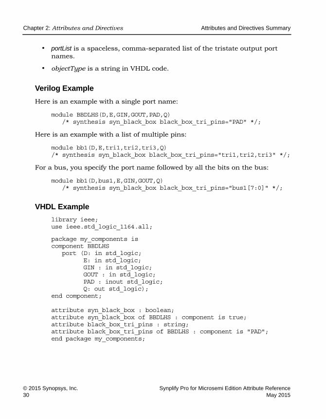
• portList is a spaceless, comma-separated list of the tristate output port names.
• objectType is a string in VHDL code.
Verilog Example
Here is an example with a single port name:
module BBDLHS(D,E,GIN,GOUT,PAD,Q) /* synthesis syn_black_box black_box_tri_pins="PAD" */;
Here is an example with a list of multiple pins:
module bb1(D,E,tri1,tri2,tri3,Q) /* synthesis syn_black_box black_box_tri_pins="tri1,tri2,tri3" */;
For a bus, you specify the port name followed by all the bits on the bus:
module bb1(D,bus1,E,GIN,GOUT,Q) /* synthesis syn_black_box black_box_tri_pins="bus1[7:0]" */;
VHDL Example
library ieee; use ieee.std_logic_1164.all;
package my_components is component BBDLHS
port (D: in std_logic; E: in std_logic; GIN : in std_logic; GOUT : in std_logic; PAD : inout std_logic; Q: out std_logic);
end component; attribute syn_black_box : boolean; attribute syn_black_box of BBDLHS : component is true; attribute black_box_tri_pins : string; attribute black_box_tri_pins of BBDLHS : component is "PAD"; end package my_components;

Attributes and Directives Summary Chapter 2: Attributes and Directives
Synplify Pro for Microsemi Edition Attribute Reference © 2015 Synopsys, Inc.May 2015 31
Multiple pins on the same component can be specified as a list:
attribute black_box_tri_pins of bb1 : component is "tri,tri2,tri3";
To apply this directive to a port that is a bus, specify all the bits on the bus:
attribute black_box_tri_pins of bb1 : component is "bus1[7:0]";

LO
Chapter 2: Attributes and Directives Attributes and Directives Summary
© 2015 Synopsys, Inc. Synplify Pro for Microsemi Edition Attribute Reference32 May 2015
full_case
Directive
For Verilog designs only. Indicates that all possible values have been given, and that no additional hardware is needed to preserve signal values.
full_case Values
Description
For Verilog designs only. When used with a case, casex, or casez statement, this directive indicates that all possible values have been given, and that no additional hardware is needed to preserve signal values.
full_case Values Syntax
This table summarizes the syntax in the following file type:
Verilog Examples
The following casez statement creates a 4-input multiplexer with a pre-decoded select bus (a decoded select bus has exactly one bit enabled at a time):
Value Description
1 (Default)
All possible values have been given and no additional hardware is needed to preserve signal values.
Verilog object /* synthesis full_case */; Verilog Examples
Attributes and Directives Summary Chapter 2: Attributes and Directives
Synplify Pro for Microsemi Edition Attribute Reference © 2015 Synopsys, Inc.May 2015 33
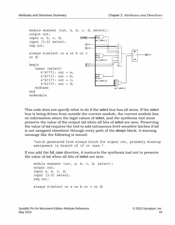
This code does not specify what to do if the select bus has all zeros. If the select bus is being driven from outside the current module, the current module has no information about the legal values of select, and the synthesis tool must preserve the value of the output out when all bits of select are zero. Preserving the value of out requires the tool to add extraneous level-sensitive latches if out is not assigned elsewhere through every path of the always block. A warning message like the following is issued:
"Latch generated from always block for signal out, probably missing assignment in branch of if or case."
If you add the full_case directive, it instructs the synthesis tool not to preserve the value of out when all bits of select are zero.
module muxnew3 (out, a, b, c, d, select); output out; input a, b, c, d; input [3:0] select; reg out; always @(select or a or b or c or d)
module muxnew1 (out, a, b, c, d, select); output out; input a, b, c, d; input [3:0] select; reg out; always @(select or a or b or c or d) begin
casez (select) 4'b???1: out = a; 4'b??1?: out = b; 4'b?1??: out = c; 4'b1???: out = d;
endcase end endmodule

LO
Chapter 2: Attributes and Directives Attributes and Directives Summary
© 2015 Synopsys, Inc. Synplify Pro for Microsemi Edition Attribute Reference34 May 2015
begin casez (select) /* synthesis full_case */
4'b???1: out = a; 4'b??1?: out = b; 4'b?1??: out = c; 4'b1???: out = d;
endcase end endmodule
If the select bus is decoded in the same module as the case statement, the synthesis tool automatically determines that all possible values are specified, so the full_case directive is unnecessary.
Assigned Default and full_case
As an alternative to full_case, you can assign a default in the case statement. The default is assigned a value of 'bx (a 'bx in an assignment is treated as a “don't care”). The software assigns the default at each pass through the casez statement in which the select bus does not match one of the explicitly given values; this ensures that the value of out is not preserved and no extraneous level-sensitive latches are generated.
The following code shows a default assignment in Verilog:
module muxnew2 (out, a, b, c, d, select); output out; input a, b, c, d; input [3:0] select; reg out;
always @(select or a or b or c or d) begin
casez (select) 4'b???1: out = a; 4'b??1?: out = b; 4'b?1??: out = c; 4'b1???: out = d; default: out = 'bx;
endcase end endmodule
Attributes and Directives Summary Chapter 2: Attributes and Directives
Synplify Pro for Microsemi Edition Attribute Reference © 2015 Synopsys, Inc.May 2015 35
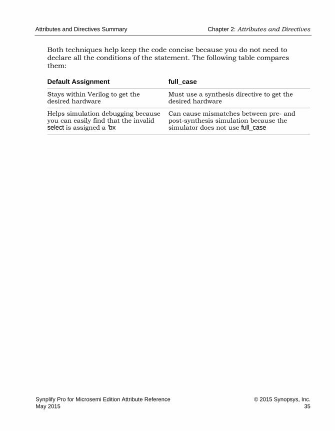
Both techniques help keep the code concise because you do not need to declare all the conditions of the statement. The following table compares them:
Default Assignment full_case
Stays within Verilog to get the desired hardware
Must use a synthesis directive to get the desired hardware
Helps simulation debugging because you can easily find that the invalid select is assigned a 'bx
Can cause mismatches between pre- and post-synthesis simulation because the simulator does not use full_case

LO
Chapter 2: Attributes and Directives Attributes and Directives Summary
© 2015 Synopsys, Inc. Synplify Pro for Microsemi Edition Attribute Reference36 May 2015
loop_limit
Directive
Verilog
Specifies a loop iteration limit for for loops in the design when the loop index is a variable, not a constant.
loop_limit Values
Description
For Verilog designs only. Specifies a loop iteration limit for for loops in the design when the loop index is a variable, not a constant. The compiler uses the default iteration limit of 1999 when the exit or terminating condition does not compute a constant value, or to avoid infinite loops. The default limit ensures the effective use of runtime and memory resources.
If your design requires a variable loop index or if the number of loops is greater than the default limit, use the loop_limit directive to specify a new limit for the compiler. If you do not, you get a compiler error. You must hard code the limit at the beginning of the loop statement. The limit cannot be an expression. The higher the value you set, the longer the runtime. To override the default limit of 2000 in the RTL, use the Loop Limit option on the Verilog tab of the Implementation Options panel. See Verilog Panel, on page 207 in the Command Reference.
Note: VHDL applications use the syn_looplimit directive (see syn_looplimit, on page 117).
loop_limit Values Syntax
The following support applies for the loop_limit directive.
Value Description
1 - 1999 Overrides the default loop limit of 2000 in the RTL.

Attributes and Directives Summary Chapter 2: Attributes and Directives
Synplify Pro for Microsemi Edition Attribute Reference © 2015 Synopsys, Inc.May 2015 37
This table summarizes the syntax in the following file:
Verilog Example
The following is an example where the loop limit is set to 2000:
module test(din,dout,clk); input[1999 : 0] din; input clk; output[1999 : 0] dout; reg[1999 : 0] dout; integer i;
always @(posedge clk) begin
/* synthesis loop_limit 2000 */ for(i=0;i<=1999;i=i+1) begin
dout[i] <= din[i]; end
end endmodule
Effect of Using loop_limit
Before using loop_limitIf the code has more than 2000 loops and the attribute is not set, the tool will produce an error.
@E:CS162 : loop_limit.v(10) | Loop iteration limit 2000 exceeded - add '// synthesis loop_limit 4000' before the loop construct
After using loop_limitCode with more than 2000 loops will not produce the loop_limit error.
Global Support Object
Yes Specifies the beginning of the loop statement.
Verilog /* synthesis loop_limit integer */ loopStatement Verilog Example

LO
Chapter 2: Attributes and Directives Attributes and Directives Summary
© 2015 Synopsys, Inc. Synplify Pro for Microsemi Edition Attribute Reference38 May 2015
parallel_case
Directive
For Verilog designs only. Forces a parallel-multiplexed structure rather than a priority-encoded structure.
Description
case statements are defined to work in priority order, executing (only) the first statement with a tag that matches the select value. The parallel_case directive forces a parallel-multiplexed structure rather than a priority-encoded struc-ture.
If the select bus is driven from outside the current module, the current module has no information about the legal values of select, and the software must create a chain of disabling logic so that a match on a statement tag disables all following statements.
However, if you know the legal values of select, you can eliminate extra priority-encoding logic with the parallel_case directive. In the following example, the only legal values of select are 4'b1000, 4'b0100, 4'b0010, and 4'b0001, and only one of the tags can be matched at a time. Specify the parallel_case directive so that tag-matching logic can be parallel and indepen-dent, instead of chained.
parallel_case Syntax
The following support applies for the parallel_case directive.
This table summarizes the syntax in the following file type:
Verilog Example
You specify the directive as a comment immediately following the select value of the case statement.
Global Support Object
No A case, casex, or casez statement declaration
Verilog object /* synthesis parallel_case */ Verilog Example

Attributes and Directives Summary Chapter 2: Attributes and Directives
Synplify Pro for Microsemi Edition Attribute Reference © 2015 Synopsys, Inc.May 2015 39
module muxnew4 (out, a, b, c, d, select); output out; input a, b, c, d; input [3:0] select; reg out; always @(select or a or b or c or d)
begin casez (select) /* synthesis parallel_case */
4'b???1: out = a; 4'b??1?: out = b; 4'b?1??: out = c; 4'b1???: out = d; default: out = 'bx;
endcase end endmodule
If the select bus is decoded within the same module as the case statement, the parallelism of the tag matching is determined automatically, and the parallel_case directive is unnecessary.
Effect of Using parallel_case
Extra logic for priority encoding (without parallel_case)
Extra logic eliminated with parallel_case

LO
Chapter 2: Attributes and Directives Attributes and Directives Summary
© 2015 Synopsys, Inc. Synplify Pro for Microsemi Edition Attribute Reference40 May 2015
pragma translate_off/pragma translate_on
Directive
Allows you to synthesize designs originally written for use with other synthesis tools without needing to modify source code. All source code that is between these two directives is ignored during synthesis.
Description
Another use of these directives is to prevent the synthesis of stimulus source code that only has meaning for logic simulation. You can use pragma translate_off/translate_on to skip over simulation-specific lines of code that are not synthesizable.
When you use pragma translate_off in a module, synthesis of all source code that follows is halted until pragma translate_on is encountered. Every pragma translate_off must have a corresponding pragma translate_on. These directives cannot be nested, therefore, the pragma translate_off directive can only be followed by a pragma translate_on directive.
Note: See also, translate_off/translate_on, on page 227. These direc-tives are implemented the same in the source code.
This table summarizes the syntax in the following file type:
Verilog /* pragma translate_off *//* pragma translate_on *//*synthesis translate_off *//*synthesis translate_on */
Verilog Example
VHDL --pragma translate_off --pragma translate_on--synthesis translate_off --synthesis translate_on
VHDL Example

Attributes and Directives Summary Chapter 2: Attributes and Directives
Synplify Pro for Microsemi Edition Attribute Reference © 2015 Synopsys, Inc.May 2015 41
Verilog Example
module test(input a, b, output dout, Nout); assign dout = a + b; //Anything between pragma translate_off/translate_on is ignored by
the synthesis tool hence only //the adder circuit above is implemented, not the multiplier
circuit below: /* synthesis translate_off */ assign Nout = a * b; /* synthesis translate_on */ endmodule
VHDL Example
library ieee; use ieee.std_logic_1164.all; use ieee.std_logic_unsigned.all; entity test is port (
a : in std_logic_vector(1 downto 0); b : in std_logic_vector(1 downto 0); dout : out std_logic_vector(1 downto 0); Nout : out std_logic_vector(3 downto 0) );
end; architecture rtl of test is begin
dout <= a + b; --Anything between pragma translate_off/translate_on is ignored by the synthesis tool hence only --the adder circuit above is implemented not the multiplier circuit below: --pragma translate_off
Nout <= a * b; --pragma translate_on end;

LO
Chapter 2: Attributes and Directives Attributes and Directives Summary
© 2015 Synopsys, Inc. Synplify Pro for Microsemi Edition Attribute Reference42 May 2015
Effect of Using pragma translate_off/pragma translate_on
Before applying the attribute:
After applying the attribute:

Attributes and Directives Summary Chapter 2: Attributes and Directives
Synplify Pro for Microsemi Edition Attribute Reference © 2015 Synopsys, Inc.May 2015 43
syn_allow_retiming
Attribute
Determines if registers can be moved across combinational logic to improve performance.
syn_allow_retiming values
Description
The syn_allow_retiming attribute determines if registers can be moved across combinational logic to improve performance.
The attribute can be applied either globally or to specific registers. Typically, you enable the global Retiming option in the UI (or the set_option -retiming 1 switch in Tcl) and use the syn_allow_retiming attribute to disable retiming for specific objects that you do not want moved.
syn_allow_retiming Syntax
Vendor Technology Synthesis Tool
Microsemi Fusion IGLOO, IGLOOe, IGLOO+ ProASIC3/3E/3L
Synplify Pro
1 | true Allows registers to be moved during retiming.
0 | false Does not allow retimed registers to be moved.
Global Object
Yes Register

LO
Chapter 2: Attributes and Directives Attributes and Directives Summary
© 2015 Synopsys, Inc. Synplify Pro for Microsemi Edition Attribute Reference44 May 2015
You can specify the attribute in the following files:
FDC Example
define_attribute {register} syn_allow_retiming {1|0}
define_global_attribute syn_allow_retiming {1|0}
Verilog Example
object /* synthesis syn_allow_retiming = 0 | 1 */;
Here is an example of applying it to a register:
module parity_check (clk,data,count_one); input clk; input [20:0]data ; output reg [3:0]count_one /* synthesis syn_allow_retiming=1*/;
integer i; reg parity= 1'b1;
always @(posedge clk) begin
for (i=0; i<21; i=i+1) if (data[i] == parity)
count_one<=count_one+1;
end endmodule
FDC define_attribute {register} syn_allow_retiming {1|0}
define_global_attribute syn_allow_retiming {1|0}
FDC Example
Verilog object /* synthesis syn_allow_retiming = 0 | 1 */; Verilog Example
VHDL attribute syn_allow_retiming of object : objectType is true | false; VHDL Example

Attributes and Directives Summary Chapter 2: Attributes and Directives
Synplify Pro for Microsemi Edition Attribute Reference © 2015 Synopsys, Inc.May 2015 45
VHDL Example
attribute syn_allow_retiming of object : objectType is true | false;
The data type is Boolean. Here is an example of applying it to a register:
LIBRARY IEEE; USE IEEE.STD_LOGIC_1164.ALL; USE IEEE.std_logic_unsigned.ALL;
ENTITY ones_cnt IS PORT (vin : IN STD_LOGIC_VECTOR (7 DOWNTO 0);
vout : OUT STD_LOGIC_VECTOR (3 DOWNTO 0); clk : IN STD_LOGIC);
END ones_cnt;
ARCHITECTURE lan OF ones_cnt IS signal vout_reg : STD_LOGIC_VECTOR (3 DOWNTO 0); attribute syn_allow_retiming : boolean; attribute syn_allow_retiming of vout_reg : signal is true;
BEGIN gen_vout: PROCESS(clk,vin)
VARIABLE count : STD_LOGIC_VECTOR(vout'RANGE); BEGIN
if rising_edge(clk) then count := (OTHERS => '0'); FOR I IN vin'RANGE LOOP
count := count + vin(i); END LOOP; vout_reg <= count;
end if; vout <= vout_reg; END PROCESS gen_vout; END lan;
See VHDL Attribute and Directive Syntax, on page 574 for different ways to specify VHDL attributes and directives.
Effect of using syn_allow_retiming
Before applying syn_allow_retiming.
Verilog output reg [3:0]count_one /* synthesis syn_allow_retiming=0*/;
VHDL attribute syn_allow_retiming of vout_reg : signal is false;

LO
Chapter 2: Attributes and Directives Attributes and Directives Summary
© 2015 Synopsys, Inc. Synplify Pro for Microsemi Edition Attribute Reference46 May 2015
The critical path and the worst slack for this scenario are given below along with the original count_one [3] register (before being retimed) as found in the design.
After applying syn_allow_retiming.
The critical path and the worst slack for this scenario are shown along with the four '*_ret' retimed registers.
Verilog output reg [3:0]count_one /* synthesis syn_allow_retiming=1*/;
VHDL attribute syn_allow_retiming of vout_reg : signal is true;

Attributes and Directives Summary Chapter 2: Attributes and Directives
Synplify Pro for Microsemi Edition Attribute Reference © 2015 Synopsys, Inc.May 2015 47
syn_black_box
Directive
Defines a module or component as a black box.
syn_black_box Value
Description
Specifies that a module or component is a black box for synthesis. A black box module has only its interface defined for synthesis; its contents are not accessible and cannot be optimized during synthesis. A module can be a black box whether or not it is empty.
Typically, you set syn_black_box on objects like the ones listed below. You do not need to define a black box for such an object if the synthesis tool includes a predefined black box for it.
• Vendor primitives and macros (including I/Os).
• User-designed macros whose functionality is defined in a schematic editor, IP, or another input source where the place-and-route tool merges design netlists from different sources.
In certain cases, the tool does not honor a syn_black_box directive:
• In mixed language designs where a black box is defined in one language at the top level but where there is an existing description for it in another language, the tool can replace the declared black box with the description from the other language.
• If your project includes black box descriptions in srs, ngc, or edf formats, the tool uses these black box descriptions even if you have specified syn_black_box at the top level.
To override this and ensure that the attribute is honored, use these methods:
• Set a syn_black_box directive on the module or entity in the HDL file that contains the description, not at the top level. The contents will be black-boxed.
Value Default Description
moduleName N/A Defines an object as a black box.

LO
Chapter 2: Attributes and Directives Attributes and Directives Summary
© 2015 Synopsys, Inc. Synplify Pro for Microsemi Edition Attribute Reference48 May 2015
• If you want to define a black box when you have an srs, ngc, or edf description for it, remove the description from the project.
Once you define a black box with syn_black_box, you use other source code directives to define timing for the black box. You must add the directives to the source code because the timing models are specific to individual instances. There are no corresponding Tcl directives you can add to a constraint file.
Black-box Source Code DirectivesUse the following directives with syn_black_box to characterize black-box timing:
Black Box Pin DefinitionsYou define the pins on a black box with these directives in the source code:
For more information on black boxes, see Instantiating Black Boxes in Verilog, on page 368, and Instantiating Black Boxes in VHDL, on page 572.
syn_black_box Syntax Specification
syn_isclock Specifies a clock port on a black box.
syn_tpd<n> Sets timing propagation for combinational delay through the black box.
syn_tsu<n> Defines timing setup delay required for input pins relative to the clock.
syn_tco<n> Defines the timing clock to output delay through the black box.
black_box_pad_pin Indicates that a black box is an I/O pad for the rest of the design.
black_box_tri_pins Indicates tristates on black boxes.
Verilog object /* synthesis syn_black_box */; Verilog Example
VHDL attribute syn_black_box of object : objectType is true; VHDL Example

Attributes and Directives Summary Chapter 2: Attributes and Directives
Synplify Pro for Microsemi Edition Attribute Reference © 2015 Synopsys, Inc.May 2015 49
Verilog Example
module top(clk, in1, in2, out1, out2);
input clk; input [1:0]in1; input [1:0]in2;
output [1:0]out1; output [1:0]out2;
add U1 (clk, in1, in2, out1); black_box_add U2 (in1, in2, out2);
endmodule
module add (clk, in1, in2, out1);
input clk; input [1:0]in1; input [1:0]in2;
output [1:0]out1; reg [1:0]out1;
always@(posedge clk) begin
out1 <= in1 + in2; end
endmodule
module black_box_add(A, B, C)/* synthesis syn_black_box */;
input [1:0]A; input [1:0]B;
output [1:0]C;
assign C = A + B;
endmodule

LO
Chapter 2: Attributes and Directives Attributes and Directives Summary
© 2015 Synopsys, Inc. Synplify Pro for Microsemi Edition Attribute Reference50 May 2015
VHDL Example
library ieee; use ieee.std_logic_1164.all; use ieee.std_logic_unsigned.all;
entity add is port(
in1 : in std_logic_vector(1 downto 0); in2 : in std_logic_vector(1 downto 0); clk : in std_logic; out1 : out std_logic_vector(1 downto 0));
end;
architecture rtl of add is begin
process(clk) begin
if(clk'event and clk='1') then out1 <= (in1 + in2);
end if; end process; end;
library ieee; use ieee.std_logic_1164.all; use ieee.std_logic_unsigned.all;
entity black_box_add is port(
A : in std_logic_vector(1 downto 0); B : in std_logic_vector(1 downto 0); C : out std_logic_vector(1 downto 0));
end;
architecture rtl of black_box_add is
attribute syn_black_box : boolean; attribute syn_black_box of rtl: architecture is true; begin
C <= A + B; end;
library ieee; use ieee.std_logic_1164.all; use ieee.std_logic_unsigned.all;

Attributes and Directives Summary Chapter 2: Attributes and Directives
Synplify Pro for Microsemi Edition Attribute Reference © 2015 Synopsys, Inc.May 2015 51
entity top is port(
in1 : in std_logic_vector(1 downto 0); in2 : in std_logic_vector(1 downto 0); clk : in std_logic; out1 : out std_logic_vector(1 downto 0); out2 : out std_logic_vector(1 downto 0));
end;
architecture rtl of top is
component add is port(
in1 : in std_logic_vector(1 downto 0); in2 : in std_logic_vector(1 downto 0); clk : in std_logic; out1 : out std_logic_vector(1 downto 0));
end component;
component black_box_add port(
A : in std_logic_vector(1 downto 0); B : in std_logic_vector(1 downto 0); C : out std_logic_vector(1 downto 0));
end component;
begin U1: add port map(in1, in2, clk, out1); U2: black_box_add port map(in1, in2, out2); end;
Effect of Using syn_black_box
When the syn_black_box attribute is not set on the black_box_add module, its content are accessible, as shown in the example below:
module black_box_add(input [1:0]A, [1:0]B, output [1:0]C);

LO
Chapter 2: Attributes and Directives Attributes and Directives Summary
© 2015 Synopsys, Inc. Synplify Pro for Microsemi Edition Attribute Reference52 May 2015
After applying syn_black_box, the contents of the black box are no longer visible:
module black_box_add(input [1:0]A, [1:0]B, output [1:0]C)/* synthesis syn_black_box */;

Attributes and Directives Summary Chapter 2: Attributes and Directives
Synplify Pro for Microsemi Edition Attribute Reference © 2015 Synopsys, Inc.May 2015 53

LO
Chapter 2: Attributes and Directives Attributes and Directives Summary
© 2015 Synopsys, Inc. Synplify Pro for Microsemi Edition Attribute Reference54 May 2015
syn_encoding
Attribute
Overrides the default FSM Compiler encoding for a state machine and applies the specified encoding.
syn_encoding Values
The default is that the tool automatically picks an encoding style that results in the best performance. To ensure that a particular encoding style is used, explicitly specify that style, using the values below:
Vendor Devices
Microsemi ProASIC3, Fusion, SmartFusion2
Value Description
onehot Only two bits of the state register change (one goes to 0, one goes to 1) and only one of the state registers is hot (driven by 1) at a time. For example: 0001, 0010, 0100, 1000Because onehot is not a simple encoding (more than one bit can be set), the value must be decoded to determine the state. This encoding style can be slower than a gray style if you have a large output decoder following a state machine.
gray More than one of the state registers can be hot. The synthesis tool attempts to have only one bit of the state registers change at a time, but it can allow more than one bit to change, depending upon certain conditions for optimization. For example: 000, 001, 011, 010, 110Because gray is not a simple encoding (more than one bit can be set), the value must be decoded to determine the state. This encoding style can be faster than a onehot style if you have a large output decoder following a state machine.

Attributes and Directives Summary Chapter 2: Attributes and Directives
Synplify Pro for Microsemi Edition Attribute Reference © 2015 Synopsys, Inc.May 2015 55
You can specify multiple values. This snippet uses safe,gray. The encoding style for register OUT is set to gray, but if the state machine reaches an invalid state the synthesis tool will reset the values to a valid state.
module prep3 (CLK, RST, IN, OUT); input CLK, RST; input [7:0] IN; output [7:0] OUT; reg [7:0] OUT; reg [7:0] current_state /* synthesis syn_encoding="safe,gray" */;
// Other code
sequential More than one bit of the state register can be hot. The synthesis tool makes no attempt at limiting the number of bits that can change at a time. For example: 000, 001, 010, 011, 100This is one of the smallest encoding styles, so it is often used when area is a concern. Because more than one bit can be set (1), the value must be decoded to determine the state. This encoding style can be faster than a onehot style if you have a large output decoder following a state machine.
safe This implements the state machine in the default encoding and adds reset logic to force the state machine to a known state if it reaches an invalid state. This value can be used in combination with any of the other encoding styles described above. You specify safe before the encoding style. The safe value is only valid for a state register, in conjunction with an encoding style specification.• For example, if the default encoding is onehot and the state machine
reaches a state where all the bits are 0, which is an invalid state, the safe value ensures that the state machine is reset to a valid state.
• If recovery from an invalid state is a concern, it may be appropriate to use this encoding style, in conjunction with onehot, sequential or gray, in order to force the state machine to reset. When you specify safe, the state machine can be reset from an unknown state to its reset state.
• If an FSM with asynchronous reset is specified with the value safe and you do not want the additional recovery logic (flip-flop on the inactive clock edge) inserted for this FSM, then use the syn_shift_resetphase attribute to remove it. See syn_shift_resetphase, on page 200 for details.
original This respects the encoding you set, but the software still does state machine and reachability analysis.
Value Description

LO
Chapter 2: Attributes and Directives Attributes and Directives Summary
© 2015 Synopsys, Inc. Synplify Pro for Microsemi Edition Attribute Reference56 May 2015
Description
This attribute takes effect only when FSM Compiler is enabled. It overrides the default FSM Compiler encoding for a state machine. For the specified encoding to take effect, the design must contain state machines that have been inferred by the FSM Compiler. Setting this attribute when syn_state_machine is set to 0 will not have any effect.
The default encoding style automatically assigns encoding based on the number of states in the state machine. Use the syn_encoding attribute when you want to override these defaults. You can also use syn_encoding when you want to disable the FSM Compiler globally but there are a select number of state registers in your design that you want extracted. In this case, use this attribute with the syn_state_machine directive on for just those specific regis-ters.
The encoding specified by this attribute applies to the final mapped netlist. For other kinds of enumerated encoding, use syn_enum_encoding. See syn_enum_encoding, on page 63 and syn_encoding Compared to syn_enum_encoding, on page 65 for more information.
Encoding Style Implementation
The encoding style is implemented during the mapping phase. A message appears when the synthesis tool extracts a state machine, for example:
@N: CL201 : "c:\design\..."|Trying to extract state machine for register current_state
The log file reports the encoding styles used for the state machines in your design. This information is also available in the FSM Viewer.
See also the following:
• For information on enabling state machine optimization for individual modules, see syn_state_machine, on page 204.
• For VHDL designs, see syn_encoding Compared to syn_enum_encoding, on page 65 for comparative usage information.
Attributes and Directives Summary Chapter 2: Attributes and Directives
Synplify Pro for Microsemi Edition Attribute Reference © 2015 Synopsys, Inc.May 2015 57
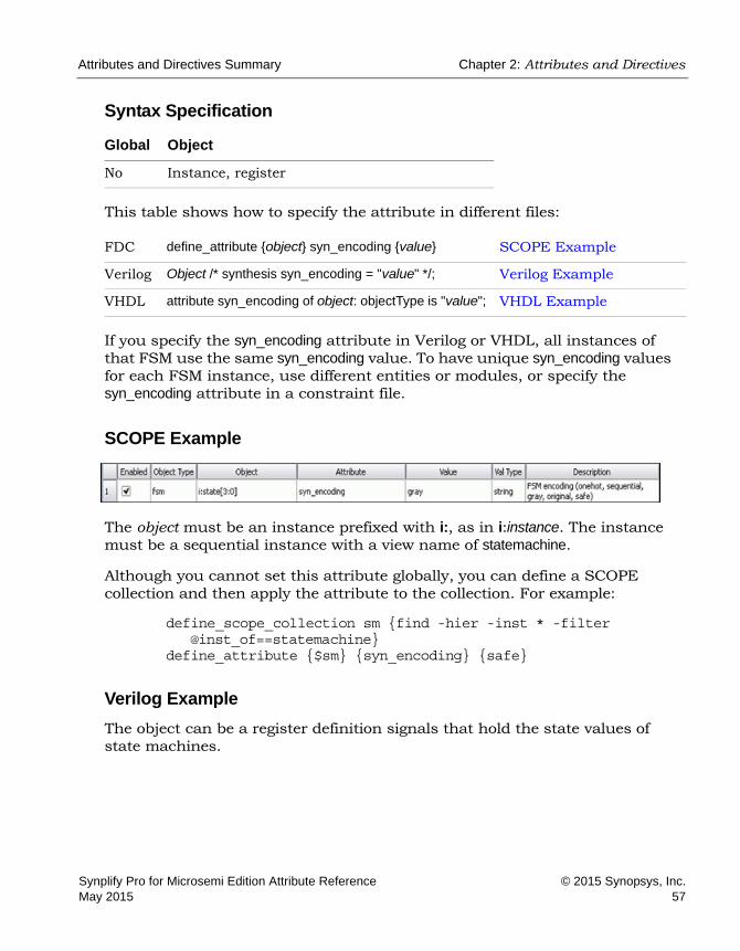
Syntax Specification
This table shows how to specify the attribute in different files:
If you specify the syn_encoding attribute in Verilog or VHDL, all instances of that FSM use the same syn_encoding value. To have unique syn_encoding values for each FSM instance, use different entities or modules, or specify the syn_encoding attribute in a constraint file.
SCOPE Example
The object must be an instance prefixed with i:, as in i:instance. The instance must be a sequential instance with a view name of statemachine.
Although you cannot set this attribute globally, you can define a SCOPE collection and then apply the attribute to the collection. For example:
define_scope_collection sm {find -hier -inst * -filter @inst_of==statemachine}
define_attribute {$sm} {syn_encoding} {safe}
Verilog Example
The object can be a register definition signals that hold the state values of state machines.
Global Object
No Instance, register
FDC define_attribute {object} syn_encoding {value} SCOPE Example
Verilog Object /* synthesis syn_encoding = "value" */; Verilog Example
VHDL attribute syn_encoding of object: objectType is "value"; VHDL Example
LO
Chapter 2: Attributes and Directives Attributes and Directives Summary
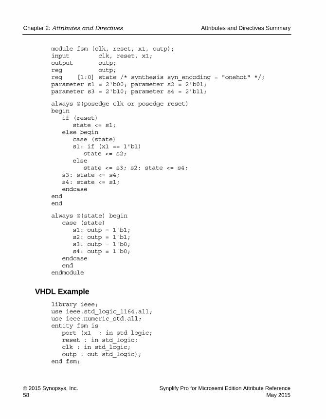
© 2015 Synopsys, Inc. Synplify Pro for Microsemi Edition Attribute Reference58 May 2015
module fsm (clk, reset, x1, outp); input clk, reset, x1; output outp; reg outp; reg [1:0] state /* synthesis syn_encoding = "onehot" */; parameter s1 = 2'b00; parameter s2 = 2'b01; parameter s3 = 2'b10; parameter s4 = 2'b11;
always @(posedge clk or posedge reset) begin
if (reset) state <= s1;
else begin case (state) s1: if (x1 == 1'b1)
state <= s2; else
state <= s3; s2: state <= s4; s3: state <= s4; s4: state <= s1; endcase
end end
always @(state) begin case (state)
s1: outp = 1'b1; s2: outp = 1'b1; s3: outp = 1'b0; s4: outp = 1'b0;
endcase end
endmodule
VHDL Example
library ieee; use ieee.std_logic_1164.all; use ieee.numeric_std.all; entity fsm is
port (x1 : in std_logic; reset : in std_logic; clk : in std_logic; outp : out std_logic);
end fsm;

Attributes and Directives Summary Chapter 2: Attributes and Directives
Synplify Pro for Microsemi Edition Attribute Reference © 2015 Synopsys, Inc.May 2015 59
architecture rtl of fsm is signal state : std_logic_vector(1 downto 0); constant s1 : std_logic_vector := "00"; constant s2 : std_logic_vector := "01"; constant s3 : std_logic_vector := "10"; constant s4 : std_logic_vector := "11"; attribute syn_encoding : string; attribute syn_encoding of state : signal is "onehot";
begin process (clk,reset)
begin if (clk'event and clk = '1') then
if (reset = '1') then state <= s1 ;
else case state is
when s1 => if x1 = '1' then
state <= s2; else
state <= s3; end if; when s2 =>
state <= s4; when s3 =>
state <= s4; when s4 =>
state <= s1; end case;
end if; end if;
end process;
process (state) begin
case state is when s1 =>
outp <= '1'; when s2 =>
outp <= '1'; when s3 =>
outp <= '0';

LO
Chapter 2: Attributes and Directives Attributes and Directives Summary
© 2015 Synopsys, Inc. Synplify Pro for Microsemi Edition Attribute Reference60 May 2015
when s4 => outp <= '0';
end case; end process; end rtl;
See VHDL Attribute and Directive Syntax, on page 574 for different ways to specify VHDL attributes and directives.
Effect of Using syn_encoding
The following figure shows the default implementation of a state machine, with these encoding details reported:
Encoding state machine state [3:0] (netlist: statemachine) original code -> new code
00 -> 00 01 -> 01 10 -> 10 11 -> 11

Attributes and Directives Summary Chapter 2: Attributes and Directives
Synplify Pro for Microsemi Edition Attribute Reference © 2015 Synopsys, Inc.May 2015 61
The next figure shows the state machine when the syn_encoding attribute is set to onehot, and the accompanying changes in the code:
Verilog
VHDL
reg [1:0] state /* synthesis syn_encoding = “onehot”*/;attribute syn_encoding of state : signal is “onehot”;
Encoding state machine state [3:0] (netlist: statemachine) original code -> new code
00 -> 0001 01 -> 0010 10 -> 0100 11 -> 1000

LO
Chapter 2: Attributes and Directives Attributes and Directives Summary
© 2015 Synopsys, Inc. Synplify Pro for Microsemi Edition Attribute Reference62 May 2015
The next figure shows the state machine when the syn_encoding attribute is set to gray:
Verilog
VHDL
reg [1:0] state /* synthesis syn_encoding = “gray”*/;attribute syn_encoding of state : signal is “gray”;
Encoding state machine state [3:0] (netlist: statemachine) original code -> new code
00 -> 00 00 -> 01 10 -> 11 11 -> 10

Attributes and Directives Summary Chapter 2: Attributes and Directives
Synplify Pro for Microsemi Edition Attribute Reference © 2015 Synopsys, Inc.May 2015 63
syn_enum_encoding
Directive
For VHDL designs. Defines how enumerated data types are implemented. The type of implementation affects the performance and device utilization.
syn_enum_encoding Values
Description
If FSM Compiler is enabled, this directive has no effect on the encoding styles of extracted state machines; the tool uses the values specified in the syn_encoding attribute instead.
However, if you have enumerated data types and you turn off the FSM Compiler so that no state machines are extracted, the syn_enum_encoding style is implemented in the final circuit. See syn_encoding Compared to syn_enum_encoding, on page 65 for more information. For step-by-step details about setting coding styles with this attribute see Defining State Machines in VHDL, on page 312 of the User Guide.
Value Description
default Automatically assigns an encoding style that results in the best performance.
sequential More than one bit of the state register can change at a time, but because more than one bit can be hot, the value must be decoded to determine the state. For example: 000, 001, 010, 011, 100.
onehot Only two bits of the state register change (one goes to 0; one goes to 1) and only one of the state registers is hot (driven by a 1) at a time. For example: 0000, 0001, 0010, 0100, 1000.
gray Only one bit of the state register changes at a time, but because more than one bit can be hot, the value must be decoded to determine the state. For example: 000, 001, 011, 010, 110.
string This can be any value you define. For example: 001, 010, 101. See Example of syn_enum_encoding for User-Defined Encoding, on page 65.

LO
Chapter 2: Attributes and Directives Attributes and Directives Summary
© 2015 Synopsys, Inc. Synplify Pro for Microsemi Edition Attribute Reference64 May 2015
A message appears in the log file when you use the syn_enum_encoding direc-tive; for example:
CD231: Using onehot encoding for type mytype (red="10000000")
syn_enum_encoding, enum_encoding, and syn_encoding
Custom attributes are attributes that are not defined in the IEEE specifica-tions, but which you or a tool vendor define for your own use. They provide a convenient back door in VHDL, and are used to better control the synthesis and simulation process. enum_encoding is one of these custom attributes that is widely used to allow specific binary encodings to be attached to objects of enumerated types.
The enum_encoding attribute is declared as follows:
attribute enum_encoding: string;
This can be either written directly in your VHDL design description, or provided to you by the tool vendor in a package. Once the attribute has been declared and given a name, it can be referenced as needed in the design description:
type statevalue is (INIT, IDLE, READ, WRITE, ERROR); attribute enum_encoding of statevalue: type is
"000 001 011 010 110";
When this is processed by a tool that supports the enum_encoding attribute, it uses the information about the statevalue encoding. Tools that do not recog-nize the enum_encoding attribute ignore the encoding.
Although it is recommended that you use syn_enum_encoding, the Synopsys FPGA tools recognize enum_encoding and treat it just like syn_enum_encoding. The tool uses the specified encoding when the FSM compiler is disabled, and ignores the value when the FSM Compiler is enabled.
If enum_encoding and syn_encoding are both defined and the FSM compiler is enabled, the tool uses the value of syn_encoding. If you have both syn_enum_encoding and enum_encoding defined, the value of syn_enum_encoding prevails.

Attributes and Directives Summary Chapter 2: Attributes and Directives
Synplify Pro for Microsemi Edition Attribute Reference © 2015 Synopsys, Inc.May 2015 65
syn_encoding Compared to syn_enum_encoding
To implement a state machine with a particular encoding style when the FSM Compiler is enabled, use the syn_encoding attribute. The syn_encoding attribute affects how the technology mapper implements state machines in the final netlist. The syn_enum_encoding directive only affects how the compiler inter-prets the associated enumerated data types. Therefore, the encoding defined by syn_enum_encoding is not propagated to the implementation of the state machine. However, when FSM Compiler is disabled, the value of syn_enum_encoding is implemented in the final circuit.
Example of syn_enum_encoding for User-Defined Encoding
library ieee; use ieee.std_logic_1164.all;
entity shift_enum is port (clk, rst : bit;
O : out std_logic_vector(2 downto 0)); end shift_enum;
architecture behave of shift_enum is type state_type is (S0, S1, S2); attribute syn_enum_encoding: string; attribute syn_enum_encoding of state_type : type is "001 010 101"; signal machine : state_type; begin
process (clk, rst) begin
if rst = ’1’ then machine <= S0;
elsif clk = ’1’ and clk’event then case machine is
when S0 => machine <= S1; when S1 => machine <= S2; when S2 => machine <= S0;
end case; end if;
end process; with machine select
O <= "001" when S0, "010" when S1, "101" when S2;
end behave;

LO
Chapter 2: Attributes and Directives Attributes and Directives Summary
© 2015 Synopsys, Inc. Synplify Pro for Microsemi Edition Attribute Reference66 May 2015
syn_enum_encoding Values Syntax
The following support applies for the syn_enum_encoding directive.
This table summarizes the syntax in the following file type:
Effect of Encoding Styles
The following figure provides an example of two versions of a design: one with the default encoding style, the other with the syn_enum_encoding directive overriding the default enumerated data types that define a set of eight colors.
Global Support Object
No/Yes Enumerated data type.
VHDL attribute syn_enum_encoding of object : objectType is "value";
VHDL Example

Attributes and Directives Summary Chapter 2: Attributes and Directives
Synplify Pro for Microsemi Edition Attribute Reference © 2015 Synopsys, Inc.May 2015 67
In this example, using the default value for syn_enum_encoding, onehot is assigned because there are eight states in this design. The onehot style imple-ments the output color as 8 bits wide and creates decode logic to convert the input sel to the output. Using sequential for syn_enum_encoding, the logic is reduced to a buffer. The size of output color is 3 bits.
See the following section for the source code used to generate the schematics above.
VHDL Example
See VHDL Attribute and Directive Syntax, on page 574 for different ways to specify VHDL attributes and directives.
Here is the code used to generate the second schematic in the previous figure. (The first schematic will be generated instead, if ”sequential” is replaced by ”onehot” as the syn_enum_encoding value.)
syn_enum_encoding = “sequential”
syn_enum_encoding = “default” Based on 8 states, onehot assigned
LO
Chapter 2: Attributes and Directives Attributes and Directives Summary
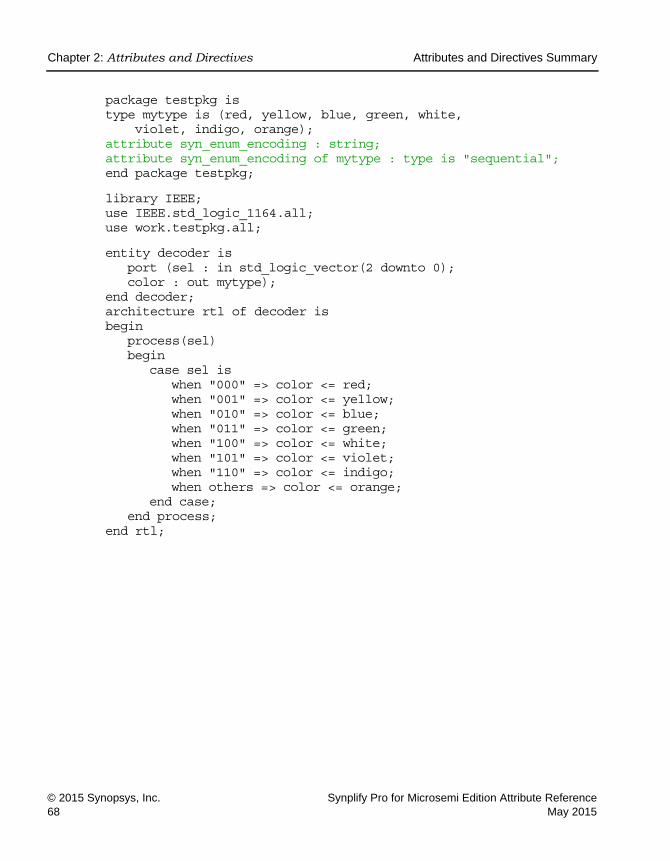
© 2015 Synopsys, Inc. Synplify Pro for Microsemi Edition Attribute Reference68 May 2015
package testpkg is type mytype is (red, yellow, blue, green, white,
violet, indigo, orange); attribute syn_enum_encoding : string; attribute syn_enum_encoding of mytype : type is "sequential"; end package testpkg;
library IEEE; use IEEE.std_logic_1164.all; use work.testpkg.all;
entity decoder is port (sel : in std_logic_vector(2 downto 0); color : out mytype);
end decoder; architecture rtl of decoder is begin
process(sel) begin
case sel is when "000" => color <= red; when "001" => color <= yellow; when "010" => color <= blue; when "011" => color <= green; when "100" => color <= white; when "101" => color <= violet; when "110" => color <= indigo; when others => color <= orange;
end case; end process;
end rtl;

Chapter 2: Attributes and Directives
Synplify Pro for Microsemi Edition Attribute Reference © 2015 Synopsys, Inc.May 2015 69
syn_global_buffers
Attribute
Specifies the number of global buffers to be used in a design.
syn_global_buffers Values
Description
The synthesis tool automatically adds global buffers for clock nets with high fanout; use this attribute to specify a maximum number of buffers and restrict the amount of global buffer resources used. Also, if there is a black box in the design that has global buffers, you can use syn_global_buffers to prevent the synthesis tool from inferring clock buffers or exceeding the number of global resources.
You specify the attribute globally on the top-level module/entity or view. For Microsemi designs, it can be any integer between 6 and 18. If you specify an integer less than 6, the software infers six global buffers.
Vendor Devices
Microsemi IGLOO/IGLOOe, ProASIC3/3E
Default Global Object
Maximum buffers available for a technology
Yes Top-level module
Value Description
An integer For Microsemi designs, it can be any integer between 6 and 18.

LO
Chapter 2: Attributes and Directives
© 2015 Synopsys, Inc. Synplify Pro for Microsemi Edition Attribute Reference70 May 2015
Syntax Specification
SCOPE Example
define_global_attribute syn_global_buffers {10}
Verilog Example
object /* synthesis syn_global_buffers = maximum */;
Here is a Verilog example:
module top (clk1, clk2, clk3, clk4, clk5, clk6, clk7,clk8,clk9, clk10, clk11, clk12, clk13, clk14, clk15, clk16, clk17, clk18, clk19, clk20, d1, d2, d3, d4, d5, d6, d7, d8, d9, d10, d11, d12, d13, d14, d15, d16, d17, d18, d19, d20, q1, q2, q3, q4, q5, q6, q7, q8, q9, q10, q11, q12, q13, q14, q15, q16, q17, q18, q19, q20, reset) /* synthesis syn_global_buffers = 10 */;
input clk1, clk2, clk3, clk4, clk5, clk6, clk7,clk8,clk9, clk10, clk11, clk12, clk13, clk14, clk15, clk16, clk17, clk18, clk19, clk20;
input d1, d2, d3, d4, d5, d6, d7, d8, d9, d10, d11, d12, d13, d14, d15, d16, d17, d18, d19, d20;
output q1, q2, q3, q4, q5, q6, q7, q8, q9, q10, q11, q12, q13, q14, q15, q16, q17, q18, q19, q20;
input reset; reg q1, q2, q3, q4, q5, q6, q7, q8, q9, q10,
q11, q12, q13, q14, q15, q16, q17, q18, q19, q20;
FDC file define_attribute {view} syn_global_buffers {maximum}define_global_attribute syn_global_buffers {maximum}
Verilog object /* synthesis syn_global_buffers = maximum */;
VHDL attribute syn_global_buffers : integer;attribute syn_global_buffers of object : objectType is maximum;

Chapter 2: Attributes and Directives
Synplify Pro for Microsemi Edition Attribute Reference © 2015 Synopsys, Inc.May 2015 71
always @(posedge clk1 or posedge reset) if (reset)
q1 <= 1'b0; else
q1 <= d1;
always @(posedge clk2 or posedge reset) if (reset)
q2 <= 1'b0; else
q2 <= d2;
always @(posedge clk3 or posedge reset) if (reset)
q3 <= 1'b0; else
q3 <= d3;
always @(posedge clk4 or posedge reset) if (reset)
q4 <= 1'b0; else
q4 <= d4;
always @(posedge clk5 or posedge reset) if (reset)
q5 <= 1'b0; else
q5 <= d5;
always @(posedge clk6 or posedge reset) if (reset)
q6 <= 1'b0; else
q6 <= d6;
always @(posedge clk7 or posedge reset) if (reset)
q7 <= 1'b0; else
q7 <= d7;
always @(posedge clk8 or posedge reset) if (reset)
q8 <= 1'b0; else
q8 <= d8;

LO
Chapter 2: Attributes and Directives
© 2015 Synopsys, Inc. Synplify Pro for Microsemi Edition Attribute Reference72 May 2015
always @(posedge clk9 or posedge reset) if (reset)
q9 <= 1'b0; else
q9 <= d9;
always @(posedge clk10 or posedge reset) if (reset)
q10 <= 1'b0; else
q10 <= d10;
always @(posedge clk11 or posedge reset) if (reset)
q11 <= 1'b0; else
q11 <= d11;
always @(posedge clk12 or posedge reset) if (reset)
q12 <= 1'b0; else
q12 <= d12
always @(posedge clk13 or posedge reset) if (reset)
q13 <= 1'b0; else
q13 <= d13;
always @(posedge clk14 or posedge reset) if (reset)
q14 <= 1'b0; else
q14 <= d14;
always @(posedge clk15 or posedge reset) if (reset)
q15 <= 1'b0; else
q15 <= d15;
always @(posedge clk16 or posedge reset) if (reset)
q16 <= 1'b0; else
q16 <= d16;
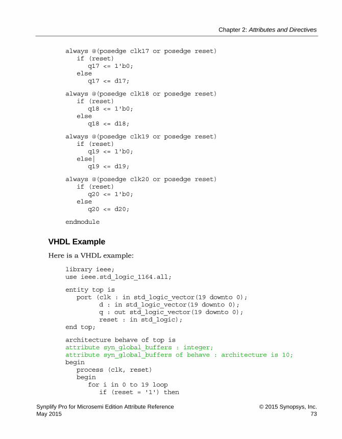
Chapter 2: Attributes and Directives
Synplify Pro for Microsemi Edition Attribute Reference © 2015 Synopsys, Inc.May 2015 73
always @(posedge clk17 or posedge reset) if (reset)
q17 <= 1'b0; else
q17 <= d17;
always @(posedge clk18 or posedge reset) if (reset)
q18 <= 1'b0; else
q18 <= d18;
always @(posedge clk19 or posedge reset) if (reset)
q19 <= 1'b0; else|
q19 <= d19;
always @(posedge clk20 or posedge reset) if (reset)
q20 <= 1'b0; else
q20 <= d20;
endmodule
VHDL Example
Here is a VHDL example:
library ieee; use ieee.std_logic_1164.all;
entity top is port (clk : in std_logic_vector(19 downto 0);
d : in std_logic_vector(19 downto 0); q : out std_logic_vector(19 downto 0); reset : in std_logic);
end top;
architecture behave of top is attribute syn_global_buffers : integer; attribute syn_global_buffers of behave : architecture is 10; begin
process (clk, reset) begin
for i in 0 to 19 loop if (reset = '1') then

LO
Chapter 2: Attributes and Directives
© 2015 Synopsys, Inc. Synplify Pro for Microsemi Edition Attribute Reference74 May 2015
q(i) <= '0'; elsif clk(i) = '1' and clk(i)' event then
q(i) <= d(i); end if;
end loop; end process;
end behave;
Effect of Using syn_global_buffers
Before applying attribute:
A message like the one below is generated:
@W:FX726: | Ignoring out-of-range global buffer count of 33 for chip view:work.top(behave)
Verilog Not applied
VHDL Not applied

Chapter 2: Attributes and Directives
Synplify Pro for Microsemi Edition Attribute Reference © 2015 Synopsys, Inc.May 2015 75
After applying attribute:
Verify results in the log file.
Verilog module top (clk1, clk2, clk3, clk4, clk5, clk6, clk7,clk8,clk9, clk10, clk11, clk12, clk13, clk14, clk15, clk16, clk17, clk18, clk19, clk20, d1, d2, d3, d4, d5, d6, d7, d8, d9, d10, d11, d12, d13, d14, d15, d16, d17, d18, d19, d20, q1, q2, q3, q4, q5, q6, q7, q8, q9, q10, q11, q12, q13, q14, q15, q16, q17, q18, q19, q20, reset) /* synthesis syn_global_buffers = 10 */;
VHDL attribute syn_global_buffers : integer; attribute syn_global_buffers of behave : architecture is 10;

LO
Chapter 2: Attributes and Directives
© 2015 Synopsys, Inc. Synplify Pro for Microsemi Edition Attribute Reference76 May 2015
syn_hier
Attribute/Directive
Controls the amount of hierarchical transformation across boundaries on module or component instances during optimization.
syn_hier Values
Vendor Devices
Microsemi SmartFusion, ProASIC3
Default Global Object
Soft Yes View
Value Description
soft (default)
The synthesis tool determines the best optimization across hierarchical boundaries. This attribute affects only the design unit in which it is specified.
firm Preserves the interface of the design unit. However, when there is cell packing across the boundary, it changes the interface and does not guarantee the exact RTL interface. This attribute affects only the design unit in which it is specified.
hard Preserves the interface of the design unit and prevents most optimizations across the hierarchy. However, the boundary optimization for constant propagation is performed. This attribute affects only the specified design units.
fixed Preserves the interface of the design unit with no exceptions. Fixed prevents all optimizations performed across hierarchical boundaries and retains the port interfaces as well.For more information, see Using syn_hier fixed, on page 82.

Chapter 2: Attributes and Directives
Synplify Pro for Microsemi Edition Attribute Reference © 2015 Synopsys, Inc.May 2015 77
Description
During synthesis, the tool dissolves as much hierarchy as possible to allow efficient logic optimization across hierarchical boundaries while maintaining optimal run times. The tool then rebuilds the hierarchy as close as possible to the original source to preserve the topology of the design.
Use the syn_hier attribute to address specific needs to maintain the original design hierarchy during optimization. This attribute gives you manual control over flattening/preserving instances, modules, or architectures in the design.
It is advised that you avoid using syn_hier="fixed" with tri-states.
Syntax Specification
remove Removes the level of hierarchy for the design unit in which it is specified. The hierarchy at lower levels is unaffected. This only affects synthesis optimization. The hierarchy is reconstructed in the netlist and Technology view schematics.
macro Preserves the interface and contents of the design with no exceptions. This value can only be set on structural netlists. (In the constraint file, or using the SCOPE editor, set syn_hier to macro on the view (the v: object type).
flatten Flattens the hierarchy of all levels below, but not the one where it is specified. This only affects synthesis optimization. The hierarchy is reconstructed in the netlist and Technology view schematics. To create a completely flattened netlist, use the syn_netlist_hierarchy attribute (syn_netlist_hierarchy, on page 130), set to false.You can use flatten in combination with other syn_hier values; the effects are described in Using syn_hier flatten with Other Values, on page 92. If you apply syn_hier to a compile point, flatten is the only valid attribute value. All other values only apply to the current level of hierarchy. The compile point hierarchy is determined by the type of compile point specified, so a syn_hier value other than flatten is redundant and is ignored.
FDC file define_attribute {object} syn_hier {value} define_global_attribute syn_hier {flatten}
Verilog object /* synthesis syn_hier = "value" */;
VHDL attribute syn_hier of object : architecture is "value";

LO
Chapter 2: Attributes and Directives
© 2015 Synopsys, Inc. Synplify Pro for Microsemi Edition Attribute Reference78 May 2015
SCOPE Example
define_global_attribute {syn_hier} {hard}
Verilog Example 1
module top( clk1,en1, data1, q1, q2 );
input clk1, en1; input data1; output q1, q2; wire cwire, rwire; wire clk_gt; assign clk_gt = en1 & clk1;
// Register module myreg U_reg (
.datain(data1),
.rst(1'b1),
.clk(clk_gt),
.en(1'b0),
.dout(rwire),
.cout(cwire) ); assign q1 = rwire; assign q2 = cwire; endmodule
module myreg ( datain, rst, clk, en, dout, cout
)/* synthesis syn_hier = "fixed" */; input clk, rst, datain, en; output dout; output cout;

Chapter 2: Attributes and Directives
Synplify Pro for Microsemi Edition Attribute Reference © 2015 Synopsys, Inc.May 2015 79
reg dreg; assign cout = en & datain; always @(posedge clk or posedge rst)
begin if (rst)
dreg <= 'b0; else
dreg <= datain; end assign dout = dreg; endmodule
Verilog Example 2
module syn_hier01 (a_i,b_i,c_i,d_i,e_i,f_i,g_i,h_i,y_o) /*synthesis syn_hier = remove/flatten/firm*/;
input a_i,b_i,c_i,d_i,e_i,f_i,_g_i_h_i; output y_o; wire a_i,b_i,c_i,d_i,e_i,f_i,g_i,h_i,y_o; assign a_in = a_i & 1'b1; syn_hier02 (a_in, b_i, c_i, d_i, e_i, f_i, g_i, h_i, y_o); endmodule
module syn_hier02 (a_i,b_i,c_i,d_i,e_i,f_i,g_i,h_i,y_o); input a_in,b_i,c_i,d_i,e_i,f_i,g_i,h_i; output y_o; wire a_in,b_i,c_i,d_i,e_i,f_i,g_i,h_i, y_o; wire ab,cd,ef,gh; assign ab = a_in + b_i; assign cd = c_i * d_i; assign ef = e_i - f_i; assign gh = g_i ^ h_i; syn_hier03 (ab, cd, ef, gh, y_o); endmodule
module syn_hier03 (ab,cd,ef,gh, y_o); input ab,cd,ef,gh,; output y_o; wire ab,cd,ef,gh; wire y_o; wire y_out; assign y_o = !y_out; syn_hier04 (ab, cd, ef, gh, y_out); endmodule

LO
Chapter 2: Attributes and Directives
© 2015 Synopsys, Inc. Synplify Pro for Microsemi Edition Attribute Reference80 May 2015
module syn_hier04 (ab,cd,ef,gh, y_out); input ab,cd,ef,gh; output y_out; wire ab,cd,ef,gh,; wire y_out; syn_hier05 (.a(ab),.b(cd),.c(ef),.d(gh),.y(y_out)); endmodule
module syn_hier05 (a,b,c,d,y); input a, b, c, d; output y; wire a, b, c, d; wire y; wire p; wire q; assign p = a & b; assign q = c & d; syn_hier06 (.p_i(p),.q_i(q),.yn(y)); endmodule
module syn_hier06 (p_i,q_i,yn); input p_i,q_i; output yn; wire p_i,q_i; wire yn; assign yn = p_i ^ q_i; endmodule
Verilog Example 3
module inc(a_in, a_out) /* synthesis syn_hier = "macro" */; input [3:0] a_in; output [3:0] a_out; endmodule
module reg4(clk, rst, d, q); input [3:0] d; input clk, rst; output [3:0] q; reg [3:0] q; always @(posedge clk or posedge rst) if(rst) q <= 0; else q <= d; endmodule
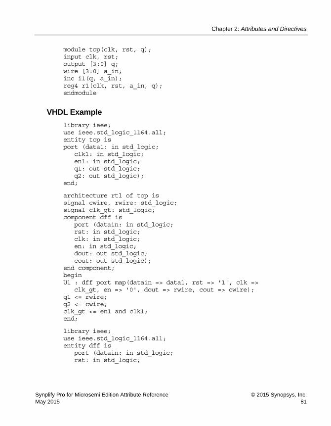
Chapter 2: Attributes and Directives
Synplify Pro for Microsemi Edition Attribute Reference © 2015 Synopsys, Inc.May 2015 81
module top(clk, rst, q); input clk, rst; output [3:0] q; wire [3:0] a_in; inc i1(q, a_in); reg4 r1(clk, rst, a_in, q); endmodule
VHDL Example
library ieee; use ieee.std_logic_1164.all; entity top is port (data1: in std_logic;
clk1: in std_logic; en1: in std_logic; q1: out std_logic; q2: out std_logic);
end;
architecture rtl of top is signal cwire, rwire: std_logic; signal clk_gt: std_logic; component dff is
port (datain: in std_logic; rst: in std_logic; clk: in std_logic; en: in std_logic; dout: out std_logic; cout: out std_logic);
end component; begin U1 : dff port map(datain => data1, rst => '1', clk =>
clk_gt, en => '0', dout => rwire, cout => cwire); q1 <= rwire; q2 <= cwire; clk_gt <= en1 and clk1; end;
library ieee; use ieee.std_logic_1164.all; entity dff is
port (datain: in std_logic; rst: in std_logic;

LO
Chapter 2: Attributes and Directives
© 2015 Synopsys, Inc. Synplify Pro for Microsemi Edition Attribute Reference82 May 2015
clk: in std_logic; en: in std_logic; dout: out std_logic; cout: out std_logic);
end;
architecture rtl of dff is signal dreg: std_logic; attribute syn_hier : string; attribute syn_hier of rtl: architecture is "fixed"; begin
process (clk, rst) begin if (rst = '1') then
dreg<= '0'; elsif (clk'event and clk ='1') then
dreg<= datain; end if; dout <= dreg; end process; end;
syn_hier in the SCOPE Window
If you use the SCOPE window to specify the syn_hier attribute, do not drag and drop the object into the SCOPE spreadsheet. Instead, first select syn_hier in the Attribute column, and then use the pull-down menu in the Object column to select the object. This is because you must set the attribute on a view (v:). If you drag and drop an object, you might not get a view object. Selecting the attribute first ensures that only the appropriate objects are listed in the Object column.
Using syn_hier fixed
When you use the fixed value with syn_hier, hierarchical boundaries are preserved with no exceptions. For example, optimizations such as constant propagation are not performed across these boundaries.
Note: It is recommended that you do not use syn_hier with the fixed value on modules that have ports driven by tri-state gates. For details, see When Using Tri-states, on page 83.

Chapter 2: Attributes and Directives
Synplify Pro for Microsemi Edition Attribute Reference © 2015 Synopsys, Inc.May 2015 83
When Using Tri-statesIt is advised that you avoid using syn_hier="fixed" with tri-states. However, if you do, here is how the software handles the following conditions:
• Tri-states driving output ports
If a module with syn_hier="fixed" includes tri-state gates that drive a primary output port, then the synthesis software retains a tri-state buffer so that the P&R tool can pack the tri-state into an output port.
• Tri-states driving internal logic
If a module with syn_hier="fixed" includes tri-state gates that drive internal logic, then the synthesis software converts the tri-state gate to a MUX and optimizes within the module accordingly.
In the following code example, myreg has syn_hier set to fixed.
module top( clk1,en1, data1, q1, q2 );
input clk1, en1; input data1; output q1, q2; wire cwire, rwire; wire clk_gt; assign clk_gt = en1 & clk1;
// Register module myreg U_reg (
.datain(data1),
.rst(1'b1),
.clk(clk_gt),
.en(1'b0),
.dout(rwire),
.cout(cwire) );
assign q1 = rwire; assign q2 = cwire; endmodule
module myreg ( datain, rst, clk, en,

LO
Chapter 2: Attributes and Directives
© 2015 Synopsys, Inc. Synplify Pro for Microsemi Edition Attribute Reference84 May 2015
dout, cout ) /* synthesis syn_hier = "fixed" */;
input clk, rst, datain, en; output dout; output cout; reg dreg; assign cout = en & datain;
always @(posedge clk or posedge rst) begin
if (rst) dreg <= 'b0;
else dreg <= datain;
end assign dout = dreg; endmodule
The HDL Analyst views show that myreg preserves its hierarchical boundaries without exceptions and prevents constant propagation optimizations.

Chapter 2: Attributes and Directives
Synplify Pro for Microsemi Edition Attribute Reference © 2015 Synopsys, Inc.May 2015 85
No Constant Propagation Optimizations and
No Gated Clock Optimizations Performed
RTL View
Technology View

LO
Chapter 2: Attributes and Directives
© 2015 Synopsys, Inc. Synplify Pro for Microsemi Edition Attribute Reference86 May 2015
Effect of Using syn_hier
Before applying attribute with the default value (soft):
Verilog Module myreg(datain,rst,clk,en,dout,cout)/*synthesis syn_hier="soft"*/;
VHDL attribute syn_hier : string; attribute syn_hier of rtl: architecture is "soft";

Chapter 2: Attributes and Directives
Synplify Pro for Microsemi Edition Attribute Reference © 2015 Synopsys, Inc.May 2015 87
After applying attribute with the value hard:
Verilog Module myreg(datain,rst,clk,en,dout,cout)/*synthesis syn_hier="hard"*/;
VHDL attribute syn_hier : string; attribute syn_hier of rtl: architecture is "hard";

LO
Chapter 2: Attributes and Directives
© 2015 Synopsys, Inc. Synplify Pro for Microsemi Edition Attribute Reference88 May 2015
After applying attribute with the value fixed:
Verilog Module myreg(datain,rst,clk,en,dout,cout)/*synthesis syn_hier="fixed"*/;
VHDL attribute syn_hier : string; attribute syn_hier of rtl: architecture is "fixed";

Chapter 2: Attributes and Directives
Synplify Pro for Microsemi Edition Attribute Reference © 2015 Synopsys, Inc.May 2015 89
Using Verilog Example 2
After applying attribute with value flatten:
Verilog module syn_hier01 (a_i,b_i,c_i,d_i,e_i,f_i,g_i,h_i,y_o)/*synthesis syn_hier = "flatten"*/;
VHDL attribute syn_hier : string; attribute syn_hier of rtl: architecture is "flatten";

LO
Chapter 2: Attributes and Directives
© 2015 Synopsys, Inc. Synplify Pro for Microsemi Edition Attribute Reference90 May 2015
After applying attribute with the value firm:
Verilog module syn_hier01 (a_i,b_i,c_i,d_i,e_i,f_i,g_i,h_i,y_o) /*synthesis syn_hier = "firm"*/ ;
VHDL attribute syn_hier : string; attribute syn_hier of rtl: architecture is "firm";

Chapter 2: Attributes and Directives
Synplify Pro for Microsemi Edition Attribute Reference © 2015 Synopsys, Inc.May 2015 91
After applying attribute with the value remove:
Verilog module syn_hier01 (a_i,b_i,c_i,d_i,e_i,f_i,g_i,h_i,y_o) /*synthesis syn_hier = "remove"*/;
VHDL attribute syn_hier : string; attribute syn_hier of rtl: architecture is "remove";
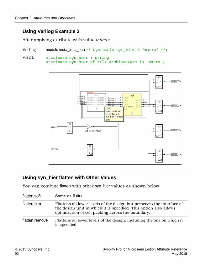
LO
Chapter 2: Attributes and Directives
© 2015 Synopsys, Inc. Synplify Pro for Microsemi Edition Attribute Reference92 May 2015
Using Verilog Example 3
After applying attribute with value macro:
Using syn_hier flatten with Other Values
You can combine flatten with other syn_hier values as shown below:
Verilog module inc(a_in, a_out) /* synthesis syn_hier = "macro" */;
VHDL attribute syn_hier : string; attribute syn_hier of rtl: architecture is "macro";
flatten,soft Same as flatten.
flatten,firm Flattens all lower levels of the design but preserves the interface of the design unit in which it is specified. This option also allows optimization of cell packing across the boundary.
flatten,remove Flattens all lower levels of the design, including the one on which it is specified.

Chapter 2: Attributes and Directives
Synplify Pro for Microsemi Edition Attribute Reference © 2015 Synopsys, Inc.May 2015 93
If you use flatten in combination with another option, the tool flattens as directed until encountering another syn_hier attribute at a lower level. The lower level syn_hier attribute then takes precedence over the higher level one.
These example demonstrate the use of the flatten and remove values to flatten the current level of the hierarchy and all levels below it (unless you have defined another syn_hier attribute at a lower level).
Verilog module top1 (Q, CLK, RST, LD, CE, D) /* synthesis syn_hier = "flatten,remove" */; // Other code
VHDL architecture struct of cpu is attribute syn_hier : string; attribute syn_hier of struct: architecture is "flatten,remove"; -- Other code
LO
Chapter 2: Attributes and Directives
© 2015 Synopsys, Inc. Synplify Pro for Microsemi Edition Attribute Reference94 May 2015
syn_insert_buffer
Attribute
Inserts a technology-specific clock buffer.
syn_insert_buffer Values
Description
Use this attribute to insert a clock buffer. You can also use it on a non-clock high fanout net, such as reset or common enable that needs global routing, to insert a global buffer for that port. The synthesis tool inserts a technology-specific clock buffer. The object you attach the attribute to also varies with the vendor.
Vendor Technologies
Microsemi IGLOO/IGLOOe/IGLOO+/IGLOO2 ProASIC3/3E/3L SmartFusion2
Vendor Value Description Technology
Microsemi CLKBUF Pads: CLKBUF
SmartFusion2, IGLOO2, IGLOO+, IGLOOe, IGLOO
HCLKBUF Pads: HCLKBUF (for nets that drive the clock pins of sequential primitives)
IGLOO+, IGLOOe, IGLOO
CLKBIBUF Pads: CLKBIBUF
SmartFusion2, IGLOO2 only
CLKINT Nets: CLKINT
SmartFusion2, IGLOO2 only
GCLKINT Nets: HCLKINT (for nets that drive the clock pins of sequential primitives)
IGLOO+, IGLOOe, IGLOO
RCLKINT Nets: RCLKINT
SmartFusion2, IGLOO2 only

Chapter 2: Attributes and Directives
Synplify Pro for Microsemi Edition Attribute Reference © 2015 Synopsys, Inc.May 2015 95
syn_insert_buffer Syntax Specification
You cannot specify this attribute as a global value.
FDC Example
Verilog Examples
In the following example, the attribute is attached to LDPRE, SEL, RST, LDCOMP, and CLK.
module prep2_2 (DATA0, DATA1, DATA2, LDPRE, SEL, RST, CLK, LDCOMP); output [7:0] DATA0; input [7:0] DATA1, DATA2; input LDPRE, SEL, RST, CLK
/* synthesis syn_insert_buffer = "GL25" */, LDCOMP; wire [7:0] DATA0_internal; prep2_1 inst1 (CLK, RST, SEL, LDCOMP, LDPRE, DATA1, DATA2,
DATA0_internal); prep2_1 inst2 (CLK, RST, SEL, LDCOMP, LDPRE, DATA0_internal,
DATA2, DATA0); endmodule
Vendor Object Description
Microsemi Instance Inserts the specified clock buffer.
FDC define_attribute object syn_insert_buffer value FDC Example
Verilog object /* synthesis syn_insert_buffer = “value” */; Verilog Examples
VHDL attribute syn_insert_buffer of object : objectType is “value”; VHDL Examples

LO
Chapter 2: Attributes and Directives
© 2015 Synopsys, Inc. Synplify Pro for Microsemi Edition Attribute Reference96 May 2015
module prep2_1 (CLK, RST, SEL, LDCOMP, LDPRE, DATA1, DATA2, DATA0); input CLK, RST, SEL, LDCOMP, LDPRE; input [7:0] DATA1, DATA2; output [7:0] DATA0; reg [7:0] DATA0; reg [7:0] highreg_output, lowreg_output; // internal registers wire compare_output = (DATA0 == lowreg_output); // comparator wire [7:0] mux_output = SEL ? DATA1 : highreg_output;
// mux registers always @ (posedge CLK or posedge RST) begin
if (RST) begin highreg_output = 0; lowreg_output = 0;
end else begin if (LDPRE)
highreg_output = DATA2; if (LDCOMP)
lowreg_output = DATA2; end
end
// counter always @(posedge CLK or posedge RST) begin
if (RST) DATA0 = 0;
else if (compare_output) // load DATA0 = mux_output;
else DATA0 = DATA0 + 1;
end
endmodule
VHDL Examples
This section provides technology-specific examples.
library ieee; use ieee.std_logic_1164.all; use ieee.std_logic_unsigned.all; use ieee.std_logic_arith.all;

Chapter 2: Attributes and Directives
Synplify Pro for Microsemi Edition Attribute Reference © 2015 Synopsys, Inc.May 2015 97
entity prep2_1 is port (clk : in bit;
rst : in bit; sel : in bit; ldcomp : in bit; ldpre : in bit; data1,data2 : in std_logic_vector(7 downto 0); data0 : out std_logic_vector(7 downto 0));
end prep2_1;
architecture behave of prep2_1 is signal equal: bit; signal mux_output: std_logic_vector(7 downto 0); signal lowreg_output: std_logic_vector(7 downto 0); signal highreg_output: std_logic_vector(7 downto 0); signal data0_i: std_logic_vector(7 downto 0); begin
compare: process(data0_i, lowreg_output) begin
if data0_i = lowreg_output then equal <= '1';
else equal <= '0';
end if; end process compare;
mux: process(sel, data1, highreg_output) begin
case sel is when '0' =>
mux_output <= highreg_output; when '1' =>
mux_output <= data1; end case;
end process mux;
registers: process (rst,clk) begin
if (rst = '1') then highreg_output <= "00000000"; lowreg_output <= "00000000";
elsif clk = '1' and clk'event then if ldpre = '1' then
highreg_output <= data2; end if;

LO
Chapter 2: Attributes and Directives
© 2015 Synopsys, Inc. Synplify Pro for Microsemi Edition Attribute Reference98 May 2015
if ldcomp = '1' then lowreg_output <= data2;
end if; end if;
end process registers;
counter: process (rst,clk) begin
if rst = '1' then data0_i <= "00000000";
elsif clk = '1' and clk'event then if equal = '1' then
data0_i <= mux_output; elsif equal = '0' then
data0_i <= data0_i + "00000001"; end if;
end if; end process counter;
data0 <= data0_i; end behave;
library ieee; use ieee.std_logic_1164.all;
entity prep2_2 is port (CLK : in bit;
RST : in bit; SEL : in bit; LDCOMP : in bit; LDPRE : in bit; DATA1,DATA2 : in std_logic_vector(7 downto 0); DATA0 : out std_logic_vector(7 downto 0));
attribute syn_insert_buffer : string; attribute syn_insert_buffer of clk : signal is "GL25"; end prep2_2;
architecture behave of prep2_2 is component prep2_1
port (clk : in bit; rst : in bit; sel : in bit; ldcomp : in bit; ldpre : in bit; data1,data2 : in std_logic_vector(7 downto 0); data0 : out std_logic_vector(7 downto 0));
end component;
signal data0_internal : std_logic_vector (7 downto 0);

Chapter 2: Attributes and Directives
Synplify Pro for Microsemi Edition Attribute Reference © 2015 Synopsys, Inc.May 2015 99
begin inst1: prep2_1 port map(clk => CLK, rst => RST, sel => SEL,
ldcomp => LDCOMP, ldpre => LDPRE, data1 => DATA1, data2 => DATA2, data0 => data0_internal);
inst2: prep2_1 port map(clk => CLK, rst => RST, sel => SEL, ldcomp => LDCOMP, ldpre => LDPRE, data1 => data0_internal, data2 => DATA2, data0 => DATA0);
end behave;

LO
Chapter 2: Attributes and Directives
© 2015 Synopsys, Inc. Synplify Pro for Microsemi Edition Attribute Reference100 May 2015
syn_insert_pad
Attribute
Removes an existing I/O buffer from a port or net when I/O buffer insertion is enabled.
syn_insert_pad Values
Description
The syn_insert_pad attribute is used when the Disable I/O Insertion option is not enabled (when buffers are automatically inserted) to allow users to selectively remove an individual buffer from a port or net or to replace a previously removed buffer.
• Setting the attribute to 0 on a port or net removes the I/O buffer (or prevents an I/O buffer from being automatically inserted).
• Setting the attribute to 1 on a port or net replaces a previously removed I/O buffer.
The syn_insert_pad attribute can only be applied through a constraint file.
Vendor Technology
Microsemi SmartFusion2 and IGLOO2
Value Description Default Global Object
0 Removes an IBUF/OBUF from a port or net None No Port, net
1 Replaces a previously removed IBUF/OBUF on a port or net.
None No Port, net

Chapter 2: Attributes and Directives
Synplify Pro for Microsemi Edition Attribute Reference © 2015 Synopsys, Inc.May 2015 101
syn_insert_pad Syntax
SCOPE Example
The following figure shows the attribute applied to the RST port using the SCOPE window:
Effect of Using syn_insert_pad
Original design before applying syn_insert_pad (or after applying syn_insert_pad with a value of 1 to replace a previously removed buffer).
FDC define_attribute {object} syn_insert_pad {1|0} SCOPE Example

LO
Chapter 2: Attributes and Directives
© 2015 Synopsys, Inc. Synplify Pro for Microsemi Edition Attribute Reference102 May 2015
Technology view after applying syn_insert_pad with a value of 0 to remove the original buffer from the RST input.

Chapter 2: Attributes and Directives
Synplify Pro for Microsemi Edition Attribute Reference © 2015 Synopsys, Inc.May 2015 103
Buffer Removed

LO
Chapter 2: Attributes and Directives
© 2015 Synopsys, Inc. Synplify Pro for Microsemi Edition Attribute Reference104 May 2015
syn_isclock
Directive
Specifies an input port on a black box as a clock.
syn_isclock Values
Description
Used with the syn_black_box directive and specifies an input port on a black box as a clock. Use the syn_isclock directive to specify that an input port on a black box is a clock, even though its name does not correspond to one of the recognized names. Using this directive connects it to a clock buffer if appro-priate. The data type is Boolean.
The syn_isclock directive is one of several directives that you can use with the syn_black_box directive to define timing for a black box. See syn_black_box, on page 47 for a list of the associated directives.
syn_isclock Values Syntax
Verilog Example
module test (myclk, a, b, tout,) /* synthesis syn_black_box */; input myclk /* synthesis syn_isclock = 1 */; input a, b; output tout; endmodule
//Top Level module top (input clk, input a, b, output fout); test U1 (clk, a, b, fout); endmodule
Value Description Object
1 | true Specifies input port is a clock. Input port on a black box
0 | false Specifies input port is not a clock. Input port on a black box
Verilog object /* synthesis syn_isclock = 1 */;
VHDL attribute syn_isclock of object: objectType is true;

Chapter 2: Attributes and Directives
Synplify Pro for Microsemi Edition Attribute Reference © 2015 Synopsys, Inc.May 2015 105
VHDL Example
See VHDL Attribute and Directive Syntax, on page 574 for different ways to specify VHDL attributes and directives.
library ieee; use ieee.std_logic_1164.all; use ieee.std_logic_unsigned.all; entity test is generic (size: integer := 8); port (tout : out std_logic_vector (size- 1 downto 0);
a : in std_logic_vector (size- 1 downto 0); b : in std_logic_vector (size- 1 downto 0);
myclk : in std_logic); attribute syn_isclock : boolean; attribute syn_isclock of myclk: signal is true; end; architecture rtl of test is attribute syn_black_box : boolean; attribute syn_black_box of rtl: architecture is true; begin end;
-- TOP Level-- library ieee; use ieee.std_logic_1164.all; use ieee.std_logic_unsigned.all; entity top is generic (size: integer := 8); port (fout : out std_logic_vector (size- 1 downto 0);
a : in std_logic_vector (size- 1 downto 0); b : in std_logic_vector (size- 1 downto 0); clk : in std_logic );
end; architecture rtl of top is component test generic (size: integer := 8); port (tout : out std_logic_vector (size- 1 downto 0);
a : in std_logic_vector (size- 1 downto 0); b : in std_logic_vector (size- 1 downto 0);
myclk : in std_logic );

LO
Chapter 2: Attributes and Directives
© 2015 Synopsys, Inc. Synplify Pro for Microsemi Edition Attribute Reference106 May 2015
end component; begin U1 : test port map (fout, a, b, clk); end;
Effect of Using syn_isclock
This figure shows the HDL Analyst Technology view before using syn_isclock:

Chapter 2: Attributes and Directives
Synplify Pro for Microsemi Edition Attribute Reference © 2015 Synopsys, Inc.May 2015 107
This figure shows the HDL Analyst Technology view after using syn_isclock:

LO
Chapter 2: Attributes and Directives
© 2015 Synopsys, Inc. Synplify Pro for Microsemi Edition Attribute Reference108 May 2015
syn_keep
Directive
Preserves the specified net and keeps it intact during optimization and synthesis.
syn_keep Values
Description
With this directive, the tool preserves the net without optimizing it away by placing a temporary keep buffer primitive on the net as a placeholder. You can view this buffer in the schematic views (see Effect of Using syn_keep, on page 112 for an example). The buffer is not part of the final netlist, so no extra logic is generated. There are various situations where this directive is useful:
• To preserve a net that would otherwise be removed as a result of optimi-zation. You might want to preserve the net for simulation results or to obtain a different synthesis implementation.
• To prevent duplicate cells from being merged during optimization. You apply the directive to the nets connected to the input of the cells you want to preserve.
• As a placeholder to apply the -through option of the set_multicycle_path or set_false_path timing constraint. This allows you to specify a unique path as a multiple-cycle or false path. Apply the constraint to the keep buffer.
Vendor Technology Global Object
All All No Net
Value Description
0 | false
(Default)Allows nets to be optimized away.
1 | true Preserves the specified net and keeps it intact during optimization and synthesis.

Chapter 2: Attributes and Directives
Synplify Pro for Microsemi Edition Attribute Reference © 2015 Synopsys, Inc.May 2015 109
• To prevent the absorption of a register into a macro. If you apply syn_keep to a reg or signal that will become a sequential object, the tool keeps the register and does not absorb it into a macro.
syn_keep with Multiple Nets in Verilog
In the following statement, syn_keep only applies to the last variable in the wire declaration, which is net c:
wire a,b,c /* synthesis syn_keep=1 */;
To apply syn_keep to all the nets, use one of the following methods:
• Declare each individual net separately as shown below.
wire a /* synthesis syn_keep=1 */; wire b /* synthesis syn_keep=1 */; wire c /* synthesis syn_keep=1 */;
• Use Verilog 2001 parenthetical comments, to declare the syn_keep direc-tive as a single line statement.
(* syn_keep=1 *) wire a,b,c;
For more information, see Attribute Examples Using Verilog 2001 Paren-thetical Comments, on page 379.
syn_keep and SystemVerilog Data Types
The SystemVerilog data types behave like logic or reg, and SystemVerilog allows them to be assigned either inside or outside an always block. If you want to use syn_keep to preserve a net with a SystemVerilog data type, like bit, byte, longint or shortint for example, you must make sure that continuous assigns are made inside an always block, not outside.

LO
Chapter 2: Attributes and Directives
© 2015 Synopsys, Inc. Synplify Pro for Microsemi Edition Attribute Reference110 May 2015
The following table shows examples of SystemVerilog data type assignments:
For information about supported SystemVerilog data types, see Data Types, on page 387.
Comparison of syn_keep, syn_preserve, and syn_noprune
Although these directives all work to preserve logic from optimization, syn_keep, syn_preserve, and syn_noprune work on different objects:
Assignment in always block, syn_keep works
assign keep1_wireand_out; assign keep2_wireand_out; always @(*) begin
keep1_bitand_out; keep2_bitand_out; keep1_byteand_out; keep2_byteand_out; keep1_longintand_out; keep2_longintand_out; keep1_shortintand_out; keep2_shortintand_out;
Assignment outside always block, syn_keep does not work
assign keep1_wireand_out; assign keep2_wireand_out; assign keep1_bitand_out; assign keep2_bitand_out; assign keep1_byteand_out; assign keep2_byteand_out; assign keep1_longintand_out; assign keep2_longintand_out; assign keep1_shortintand_out; assign keep2_shortintand_out;
syn_keep Only works on nets and combinational logic. It ensures that the wire is kept during synthesis, and that no optimizations cross the wire. This directive is usually used to prevent unwanted optimizations and to ensure that manually created replications are preserved. When applied to a register, the register is preserved and not absorbed into a macro.
syn_preserve Ensures that registers are not optimized away.
syn_noprune Ensures that a black box is not optimized away when its outputs are unused (i.e., when its outputs do not drive any logic).

Chapter 2: Attributes and Directives
Synplify Pro for Microsemi Edition Attribute Reference © 2015 Synopsys, Inc.May 2015 111
See Preserving Objects from Being Optimized Away, on page 347 in the User Guide for more information.
syn_keep Syntax
Verilog Example
object /* synthesis syn_keep = 1 */;
object is a wire or reg declaration. Make sure that there is a space between the object name and the beginning of the comment slash (/).
Here is the source code used to produce the results shown in Effect of Using syn_keep, on page 112.
module example2(out1, out2, clk, in1, in2); output out1, out2; input clk; input in1, in2; wire and_out; wire keep1 /* synthesis syn_keep=1 */; wire keep2 /* synthesis syn_keep=1 */; reg out1, out2; assign and_out=in1&in2; assign keep1=and_out; assign keep2=and_out;
always @(posedge clk)begin; out1<=keep1; out2<=keep2;
end endmodule
VHDL Example
attribute syn_keep of object : objectType is true;
object is a single or multiple-bit signal.
Verilog object /* synthesis syn_keep = 1 */; Verilog Example
VHDL attribute syn_keep : booleanattribute syn_keep of object : objectType is true;
VHDL Example

LO
Chapter 2: Attributes and Directives
© 2015 Synopsys, Inc. Synplify Pro for Microsemi Edition Attribute Reference112 May 2015
Here is the source code used to produce the schematics shown in Effect of Using syn_keep, on page 112.
entity example2 is port (in1, in2 : in bit;
clk : in bit; out1, out2 : out bit);
end example2;
architecture rt1 of example2 is attribute syn_keep : boolean; signal and_out, keep1, keep2: bit; attribute syn_keep of keep1, keep2 : signal is true; begin and_out <= in1 and in2; keep1 <= and_out; keep2 <= and_out;
process(clk) begin
if (clk'event and clk = '1') then out1 <= keep1; out2 <= keep2;
end if; end process;
end rt1;
Effect of Using syn_keep
When you use syn_keep on duplicate logic, the tool retains it instead of optimizing it away. The following figure shows the Technology view for two versions of a design.
In the first, syn_keep is set on the nets connected to the inputs of the registers out1 and out2, to prevent sharing. The second figure shows the same design without syn_keep. Setting syn_keep on the input wires for the registers ensures that the design has duplicate registered outputs for out1 and out2. If you do not apply syn_keep to keep1 and keep2, the software optimizes out1 and out2, and only has one register.

Chapter 2: Attributes and Directives
Synplify Pro for Microsemi Edition Attribute Reference © 2015 Synopsys, Inc.May 2015 113
With syn_keep
Without syn_keep

LO
Chapter 2: Attributes and Directives
© 2015 Synopsys, Inc. Synplify Pro for Microsemi Edition Attribute Reference114 May 2015
syn_loc Attribute
The syn_loc attribute specifies the location (placement) of ports.
syn_loc Values
Description
Specifies pin locations for I/O pins and cores, and forward-annotates this information to the place-and-route tool. This attribute can only be specified in a top-level source file or a constraint file.
syn_loc Syntax
pinNumbers is a comma-separated list of pin or placement numbers. Refer to the vendor data book for valid values.
Vendor Technology
Microsemi SmartFusion
Value Description
Pin numbers Assigns pin numbers to ports.
Default Global Attribute Object
Not Applicable No Port
FDC define_attribute portDesignName {syn_loc} {pinNumbers} FDC Example
Verilog object /* synthesis syn_loc = "pinNumbers" */ Verilog Example
VHDL attribute syn_loc of object : objectType is "pinNumbers"; VHDL Example

Chapter 2: Attributes and Directives
Synplify Pro for Microsemi Edition Attribute Reference © 2015 Synopsys, Inc.May 2015 115
FDC Example
The following are examples of using this attribute:
You can also specify locations for individual bus bits with this attribute:
Verilog Example
module test(a, b, clk, out1); input clk; input [2:0]a; input [2:0]b; output reg [2:0] out1/* synthesis syn_loc = "D10,B6,Y6,M7*/;
always@(posedge clk) begin
out1 <= a + b; end endmodule
VHDL Example
Microsemi define_attribute {CR_DIN[3:0]} syn_loc {M7, Y6, B6, D10}
Microsemi
define_attribute {CR_DIN[3]} syn_loc {M7} define_attribute {CR_DIN[2]} syn_loc {Y6} define_attribute {CR_DIN[1]} syn_loc {B6} define_attribute {CR_DIN[0]} syn_loc {D10}
Specify the b: prefix and the bit slice:define_attribute {b:CR_DIN[0]} syn_loc {D10} define_attribute {b:CR_DIN[1]} syn_loc {B6} define_attribute {b:CR_DIN[2]} syn_loc {Y6} define_attribute {b:CR_DIN[3]} syn_loc {M7}
Microsemi input [3:0] CR_DIN /* synthesis syn_loc = "M7,Y6, B6, D10"
Microsemi attribute syn_loc : string;attribute syn_loc of CR_DIN : signal is "M7, Y6, B6, D10";

LO
Chapter 2: Attributes and Directives
© 2015 Synopsys, Inc. Synplify Pro for Microsemi Edition Attribute Reference116 May 2015
library ieee; use ieee.std_logic_1164.all; entity test is
generic (s : integer := 2);
port ( clk: in std_logic; in1: in std_logic_vector(s downto 0); in2: in std_logic_vector(s downto 0); d_out: out std_logic_vector(5 downto 0)); attribute syn_loc : string; attribute syn_loc of d_out:signal is "M7,Y6,B6,D10";
end test; architecture beh of test is begin
process (clk) begin
if rising_edge(clk) then d_out <= in1 & in2;
end if; end process;
end beh;

Chapter 2: Attributes and Directives
Synplify Pro for Microsemi Edition Attribute Reference © 2015 Synopsys, Inc.May 2015 117
syn_looplimit
Directive
VHDL
Specifies a loop iteration limit for while loops in the design.
Description
The syn_looplimit directive specifies a loop iteration limit for while loops in the design when the loop index is a variable, not a constant. If your design requires a variable loop index, use the syn_looplimit directive to specify a limit for the compiler. If you do not, you can get a “while loop not terminating” compiler error. The limit cannot be an expression. The higher the value set, the longer the runtime. To override the default limit of 2000 in the RTL, use the Loop Limit option on the VHDL tab of the Implementation Options panel. See VHDL Panel, on page 204 in the Command Reference.
Verilog applications use the loop_limit directive (see loop_limit, on page 36).
syn_looplimit Summary
syn_looplimit Syntax
VHDL Example
library ieee; use ieee.std_logic_1164.all; use IEEE.numeric_std.all; entity test is
Technology Global Object
All Yes Architecture
VHDL attribute syn_looplimit : integer; attribute syn_looplimit of labelName : label is value;
VHDL Example

LO
Chapter 2: Attributes and Directives
© 2015 Synopsys, Inc. Synplify Pro for Microsemi Edition Attribute Reference118 May 2015
port ( clk : in std_logic; d_in : in std_logic_vector(2999 downto 0); d_out: out std_logic_vector(2999 downto 0) );
end test;
architecture beh of test is
attribute syn_looplimit : integer; attribute syn_looplimit of loopabc: label is 3000;
begin process (clk) variable i, k: integer := 0; begin if (clk'event and clk = '1') then
k:=0; loopabc: while (k<2999) loop
k:= k+ 1; d_out(k) <= d_in(k);
end loop loopabc; d_out(0) <= d_in(0);
end if; end process;
end beh;
Chapter 2: Attributes and Directives
Synplify Pro for Microsemi Edition Attribute Reference © 2015 Synopsys, Inc.May 2015 119
syn_maxfan
Attribute
Overrides the default (global) fanout guide for an individual input port, net, or register output.
syn_maxfan Value
Description
syn_maxfan overrides the global fanout for an individual input port, net, or register output. You set the default Fanout Guide for a design through the Device panel on the Implementation Options dialog box or with the set_option -fanout_limit command or -fanout_guide in the project file. Use the syn_maxfan attribute to specify a different (local) value for individual I/Os.
Generally, syn_maxfan and the default fanout guide are suggested guidelines only, but in certain cases they function as hard limits.
• When they are guidelines, the synthesis tool takes them into account, but does not always respect them absolutely. The synthesis tool does not respect the syn_maxfan limit if the limit imposes constraints that interfere with optimization.
You can apply the syn_maxfan attribute to the following objects:
• Registers or instances. You can also apply it to a module or entity. If you attach the attribute to a lower-level module or entity that is subse-quently optimized during synthesis, the synthesis tool moves the syn_maxfan attribute up to the next higher level. If you do not want syn_maxfan moved up during optimization, set the syn_hier attribute for the entity or module to hard. This prevents the module or entity from being flattened when the design is optimized.
Vendor Technology Default
Microsemi All None
value Integer for the maximum fanout

LO
Chapter 2: Attributes and Directives
© 2015 Synopsys, Inc. Synplify Pro for Microsemi Edition Attribute Reference120 May 2015
• Ports or nets. If you apply the attribute to a net, the synthesis tool creates a KEEPBUF component and attaches the attribute to it to prevent the net itself from being optimized away during synthesis.
The syn_maxfan attribute is often used along with the syn_noclockbuf attribute on an input port that you do not want buffered. There are a limited number of clock buffers in a design, so if you want to save these special clock buffer resources for other clock inputs, put the syn_noclockbuf attribute on the clock signal. If timing for that clock signal is not critical, you can turn off buffering completely to save area. To turn off buffering, set the maximum fanout to a very high number; for example, 1000.
Similarly, you use syn_maxfan with the syn_replicate attribute in certain technologies to control replication.
syn_maxfan Syntax
FDC Example
define_attribute {object} syn_maxfan {integer}
Verilog Example
object /* synthesis syn_maxfan = "value" */;
For example:
Global Object Type
No Registers, instances, ports, nets
FDC define_attribute {object} syn_maxfan {integer} FDC Example
Verilog object /* synthesis syn_maxfan = "value" */; Verilog Example
VHDL attribute syn_maxfan of object : objectType is "value"; VHDL Example

Chapter 2: Attributes and Directives
Synplify Pro for Microsemi Edition Attribute Reference © 2015 Synopsys, Inc.May 2015 121
module syn_maxfan (clk,rst,a,b,c); input clk,rst; input [7:0] a,b; output reg [7:0] c;
reg d/* synthesis syn_maxfan=3 */;
always @ (posedge clk) begin
if(rst) d <= 0;
else d <= ~d;
end
always @ (posedge d) begin
c <= a^b; end
endmodule

LO
Chapter 2: Attributes and Directives
© 2015 Synopsys, Inc. Synplify Pro for Microsemi Edition Attribute Reference122 May 2015
VHDL Example
attribute syn_maxfan of object : objectType is "value";
See VHDL Attribute and Directive Syntax, on page 574 for different ways to specify VHDL attributes and directives.
library ieee; use ieee.std_logic_1164.all; use ieee.numeric_std.all; entity maxfan is
port (a : in std_logic_vector(7 downto 0); b : in std_logic_vector(7 downto 0); rst : in std_logic; clk : in std_logic; c : out std_logic_vector(7 downto 0));
end maxfan;
architecture rtl of maxfan is signal d : std_logic;
attribute syn_maxfan : integer; attribute syn_maxfan of d : signal is 3;
begin
process (clk) begin if (clk'event and clk = '1') then
if (rst = '1') then d <= '0'; else d <= not d;
end if; end if;
end process;
process (d) begin
if (d'event and d = '1') then
c <= a and b; end if; end process;
end rtl;

Chapter 2: Attributes and Directives
Synplify Pro for Microsemi Edition Attribute Reference © 2015 Synopsys, Inc.May 2015 123
Effect of Using syn_maxfan
Before applying syn_maxfan:
After applying the attribute syn_maxfan, the register d is replicated three times (shown in red) because its actual fanout is 8, but we have restricted it to 3.
Verilog reg d/* synthesis syn_maxfan=3 */;
VHDL attribute syn_maxfan of d : signal is 3;
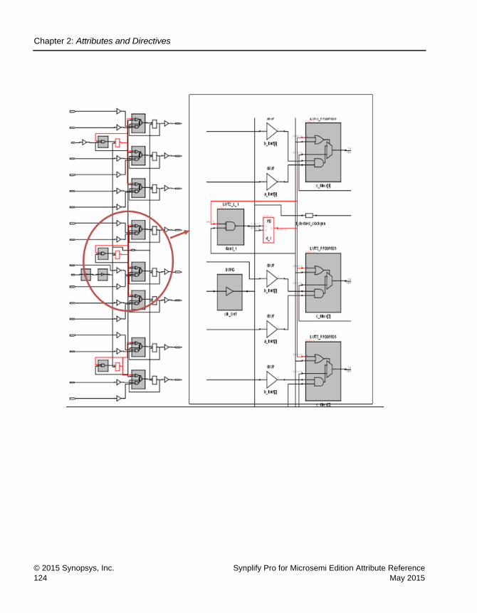
LO
Chapter 2: Attributes and Directives
© 2015 Synopsys, Inc. Synplify Pro for Microsemi Edition Attribute Reference124 May 2015

Chapter 2: Attributes and Directives
Synplify Pro for Microsemi Edition Attribute Reference © 2015 Synopsys, Inc.May 2015 125
syn_multstyle
Attribute
Determines how multipliers are implemented.
syn_multstyle Values
This table lists the valid values for each vendor:
Description
This attribute specifies whether the multipliers are implemented as dedicated hardware blocks or as logic. The implementation varies with the technology, as shown in the preceding table.
syn_multstyle Syntax
Vendor Device Values
Microsemi SmartFusion2IGLOO2
dsp | logic
Value Description Default
logic Implements the multipliers as logic. -
dsp Implements the multipliers as DSP blocks. X
Microsemi • dsp Uses dedicated hardware DSP blocks. This is the default.
• logic Uses logic instead of dedicated resources.
Global Attribute Object
Yes Module or instance

LO
Chapter 2: Attributes and Directives
© 2015 Synopsys, Inc. Synplify Pro for Microsemi Edition Attribute Reference126 May 2015
The following shows the attribute syntax when specified in different files:
See VHDL Attribute and Directive Syntax, on page 574 for different ways to specify VHDL attributes and directives.
SCOPE Example
This SCOPE example specifies that the multipliers be globally implemented as logic:
This example specifies that multipliers be implemented as logic.
define_attribute {temp[15:0]} syn_multstyle {logic}
FDC define_attribute {instance} syn_multstyle {logic | dsp}
Global attribute: define_global_attribute syn_multstyle {logic | dsp}
SCOPE Example
Verilog input net /* synthesis syn_multstyle = “logic | dsp” */;
Verilog Example
VHDL attribute syn_multstyle of instance : signal is “logic | dsp”;
VHDL Example

Chapter 2: Attributes and Directives
Synplify Pro for Microsemi Edition Attribute Reference © 2015 Synopsys, Inc.May 2015 127
Verilog Example
module mult(a,b,c,r,en); input [7:0] a,b; output [15:0] r; input [15:0] c; input en; wire [15:0] temp /* synthesis syn_multstyle="logic" */; assign temp = a*b; assign r = en ? temp: c; endmodule
VHDL Example
library ieee; use ieee.std_logic_1164.all; USE ieee.numeric_std.all;
entity mult is port (clk : in std_logic;
a : in std_logic_vector(7 downto 0); b : in std_logic_vector(7 downto 0); c : out std_logic_vector(15 downto 0))
end mults;
architecture rtl of mult is signal mult_i : std_logic_vector(15 downto 0); attribute syn_multstyle : string; attribute syn_multstyle of mult_i : signal is "logic"; begin mult_i <= std_logic_vector(unsigned(a)*unsigned(b));
process(clk) begin
if (clk'event and clk = '1') then c <= mult_i;
end if; end process;
end rtl;
Effect of Using syn_multstyle in a Microsemi Design
In a Microsemi design, you can specify that the multipliers be implemented as logic or as dedicated DSP blocks. The following figure shows a multiplier implemented as DSP:

LO
Chapter 2: Attributes and Directives
© 2015 Synopsys, Inc. Synplify Pro for Microsemi Edition Attribute Reference128 May 2015
Verilog
VHDL
wire [15:0] temp /* synthesis syn_multstyle = “dsp”*/;attribute syn_multstyle of mult_i : signal is “dsp”;

Chapter 2: Attributes and Directives
Synplify Pro for Microsemi Edition Attribute Reference © 2015 Synopsys, Inc.May 2015 129
The following figure shows the same Microsemi design with the multiplier imple-mented as logic when the attribute is set to logic:
Verilog
VHDL
wire [15:0] temp /* synthesis syn_multstyle = “logic”*/;attribute syn_multstyle of mult_i : signal is “logic”;

LO
Chapter 2: Attributes and Directives
© 2015 Synopsys, Inc. Synplify Pro for Microsemi Edition Attribute Reference130 May 2015
syn_netlist_hierarchy
Attribute
Determines if the generated netlist is to be hierarchical or flat.
syn_netlist_hierarchy Values
Description
A global attribute that controls the generation of hierarchy in the EDIF output netlist when assigned to the top-level module in your design. The default (1/true) allows hierarchy generation, and setting the attribute to 0/false flattens the hierarchy and produces a completely flattened output netlist.
Syntax Specification
Vendor Technology
Microsemi IGLOO families
Value Description Default
1/true Allows hierarchy generation Default
0/false Flattens hierarchy in the netlist
Global Object
Yes Module/Architecture
FDC define_global_attribute syn_netlist_hierarchy {0|1} SCOPE Example
Verilog object /* synthesis syn_netlist_hierarchy = 0|1 */; Verilog Example
VHDL attribute syn_netlist_hierarchy of object : objectType is true|false; VHDL Example
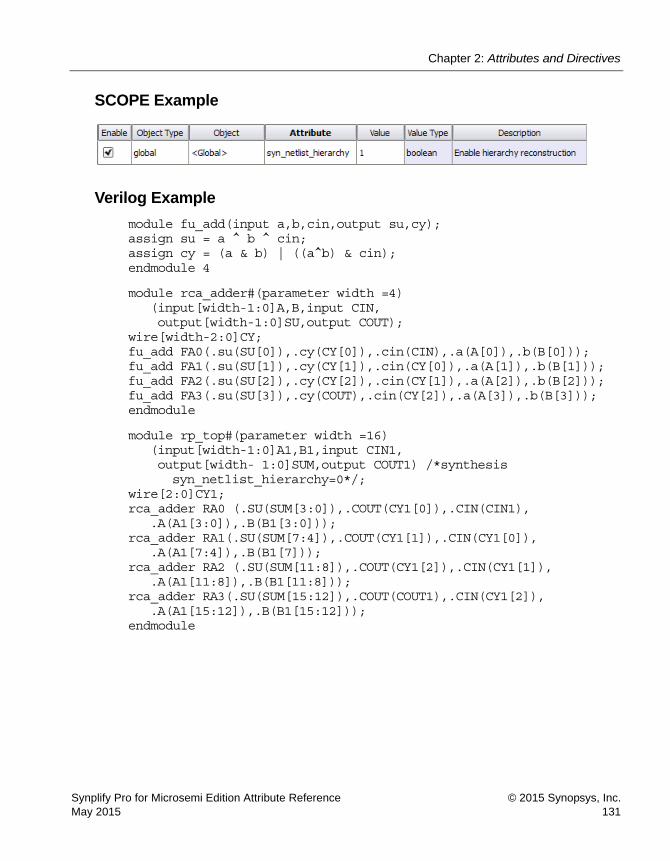
Chapter 2: Attributes and Directives
Synplify Pro for Microsemi Edition Attribute Reference © 2015 Synopsys, Inc.May 2015 131
SCOPE Example
Verilog Example
module fu_add(input a,b,cin,output su,cy); assign su = a ^ b ^ cin; assign cy = (a & b) | ((a^b) & cin); endmodule 4
module rca_adder#(parameter width =4) (input[width-1:0]A,B,input CIN, output[width-1:0]SU,output COUT);
wire[width-2:0]CY; fu_add FA0(.su(SU[0]),.cy(CY[0]),.cin(CIN),.a(A[0]),.b(B[0])); fu_add FA1(.su(SU[1]),.cy(CY[1]),.cin(CY[0]),.a(A[1]),.b(B[1])); fu_add FA2(.su(SU[2]),.cy(CY[2]),.cin(CY[1]),.a(A[2]),.b(B[2])); fu_add FA3(.su(SU[3]),.cy(COUT),.cin(CY[2]),.a(A[3]),.b(B[3])); endmodule
module rp_top#(parameter width =16) (input[width-1:0]A1,B1,input CIN1, output[width- 1:0]SUM,output COUT1) /*synthesis
syn_netlist_hierarchy=0*/; wire[2:0]CY1; rca_adder RA0 (.SU(SUM[3:0]),.COUT(CY1[0]),.CIN(CIN1),
.A(A1[3:0]),.B(B1[3:0])); rca_adder RA1(.SU(SUM[7:4]),.COUT(CY1[1]),.CIN(CY1[0]),
.A(A1[7:4]),.B(B1[7])); rca_adder RA2 (.SU(SUM[11:8]),.COUT(CY1[2]),.CIN(CY1[1]),
.A(A1[11:8]),.B(B1[11:8])); rca_adder RA3(.SU(SUM[15:12]),.COUT(COUT1),.CIN(CY1[2]),
.A(A1[15:12]),.B(B1[15:12])); endmodule
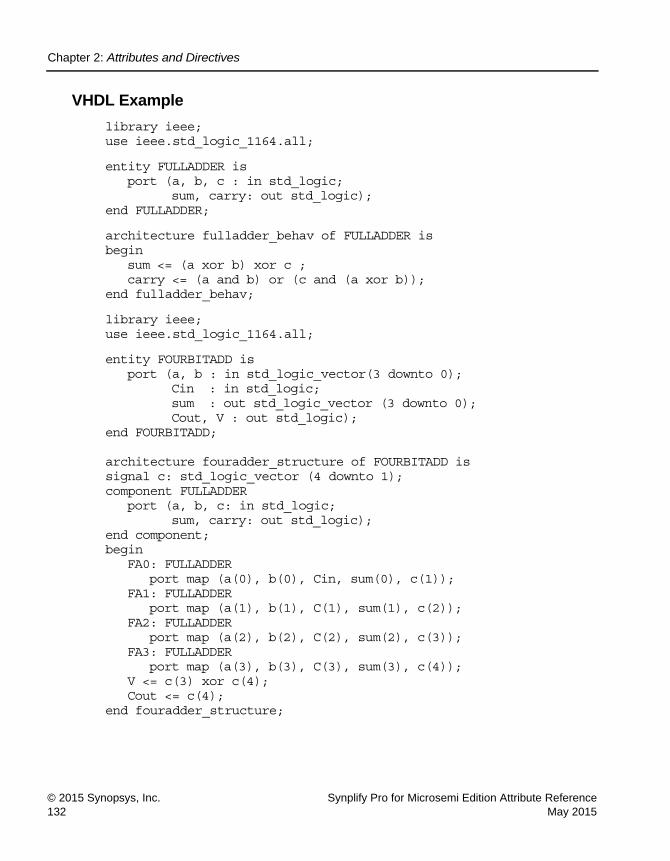
LO
Chapter 2: Attributes and Directives
© 2015 Synopsys, Inc. Synplify Pro for Microsemi Edition Attribute Reference132 May 2015
VHDL Example
library ieee; use ieee.std_logic_1164.all;
entity FULLADDER is port (a, b, c : in std_logic;
sum, carry: out std_logic); end FULLADDER;
architecture fulladder_behav of FULLADDER is begin
sum <= (a xor b) xor c ; carry <= (a and b) or (c and (a xor b));
end fulladder_behav;
library ieee; use ieee.std_logic_1164.all;
entity FOURBITADD is port (a, b : in std_logic_vector(3 downto 0);
Cin : in std_logic; sum : out std_logic_vector (3 downto 0); Cout, V : out std_logic);
end FOURBITADD; architecture fouradder_structure of FOURBITADD is signal c: std_logic_vector (4 downto 1); component FULLADDER
port (a, b, c: in std_logic; sum, carry: out std_logic);
end component; begin
FA0: FULLADDER port map (a(0), b(0), Cin, sum(0), c(1));
FA1: FULLADDER port map (a(1), b(1), C(1), sum(1), c(2));
FA2: FULLADDER port map (a(2), b(2), C(2), sum(2), c(3));
FA3: FULLADDER port map (a(3), b(3), C(3), sum(3), c(4));
V <= c(3) xor c(4); Cout <= c(4);
end fouradder_structure;

Chapter 2: Attributes and Directives
Synplify Pro for Microsemi Edition Attribute Reference © 2015 Synopsys, Inc.May 2015 133
library ieee; use ieee.std_logic_1164.all;
entity BITADD is port (A, B: in std_logic_vector(15 downto 0);
Cin : in std_logic; SUM : out std_logic_vector (15 downto 0); COUT: out std_logic);
end BITADD;
architecture adder_structure of BITADD is attribute syn_netlist_hierarchy : boolean; attribute syn_netlist_hierarchy of adder_structure:
architecture is false; signal C: std_logic_vector (4 downto 1);
component FOURBITADD port (a, b: in std_logic_vector(3 downto 0);
Cin : in std_logic; sum : out std_logic_vector (3 downto 0); Cout, V: out std_logic);
end component;
begin F1: FOURBITADD
port map (A(3 downto 0),B(3 downto 0), Cin, SUM(3 downto 0),C(1));
F2: FOURBITADD port map (A(7 downto 4),B(7 downto 4),
C(1), SUM(7 downto 4),C(2)); F3: FOURBITADD
port map (A(11 downto 8),B(11 downto 8), C(2), SUM(11 downto 8),C(3));
F4: FOURBITADD port map (A(15 downto 12),B(15 downto 12),
C(3), SUM(15 downto 12),C(4)); COUT <= c(4);
end adder_structure;
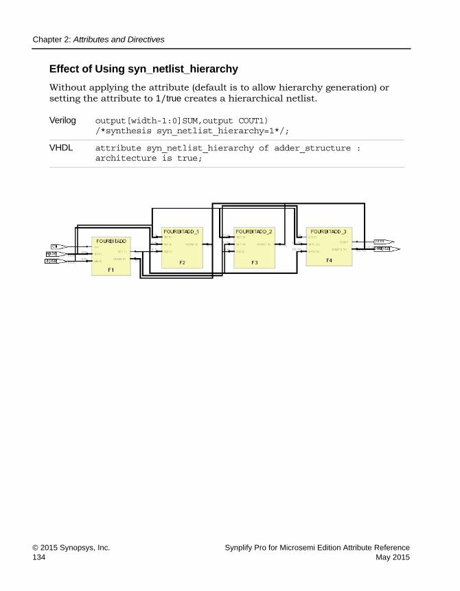
LO
Chapter 2: Attributes and Directives
© 2015 Synopsys, Inc. Synplify Pro for Microsemi Edition Attribute Reference134 May 2015
Effect of Using syn_netlist_hierarchy
Without applying the attribute (default is to allow hierarchy generation) or setting the attribute to 1/true creates a hierarchical netlist.
Verilog output[width-1:0]SUM,output COUT1) /*synthesis syn_netlist_hierarchy=1*/;
VHDL attribute syn_netlist_hierarchy of adder_structure : architecture is true;

Chapter 2: Attributes and Directives
Synplify Pro for Microsemi Edition Attribute Reference © 2015 Synopsys, Inc.May 2015 135
Applying the attribute with a value of 0/false creates a flattened netlist.
syn_hier flatten and syn_netlist_hierarchy
The syn_hier=flatten attribute and the syn_netlist_hierarchy=false attributes both flatten hierarchy, but work slightly differently. Use the syn_netlist_hierarchy attribute if you want a completely flattened netlist (this attribute flattens all levels of hierarchy). When you set syn_hier=flatten, you flatten the hierarchical levels below the component on which it is set, but you do not flatten the current hierarchical level where it is set. Refer to syn_hier, on page 76 for information about this attribute.
Verilog output[width-1:0]SUM,output COUT1) /*synthesis syn_netlist_hierarchy=0*/;
VHDL attribute syn_netlist_hierarchy of adder_structure : architecture is false;

LO
Chapter 2: Attributes and Directives
© 2015 Synopsys, Inc. Synplify Pro for Microsemi Edition Attribute Reference136 May 2015
syn_noarrayports
Attribute
Specifies signals as scalar in the output file.
syn_noarrayports Values
Description
Use this attribute to specify that the ports of a design unit be treated as individual signals (scalars), not as buses (arrays) in the output file.
Syntax Specification
SCOPE Example
Vendor Devices
Microsemi SmartFusion, ProASIC3E
Default Global Object
0 Yes Module/Architecture
SCOPE define_global_attribute syn_noarrayports {0|1}
Verilog object /* synthesis syn_noarrayports = 0 | 1;
VHDL attribute syn_noarrayports of object : objectType is true | false;

Chapter 2: Attributes and Directives
Synplify Pro for Microsemi Edition Attribute Reference © 2015 Synopsys, Inc.May 2015 137
Verilog Example
module adder8(cout,sum,a,b,cin) /* synthesis syn_noarrayports = "1" */;
input[7:0] a,b; input cin; output reg[7:0] sum; output reg cout; always@(*) begin {cout,sum}=a+b+cin; end endmodule
VHDL Example
library ieee; use ieee.std_logic_1164.all; use ieee.std_logic_arith.all; use ieee.std_logic_unsigned.all; entity ADDER is generic(n: natural :=8); port( A: in std_logic_vector(n-1 downto 0);
B: in std_logic_vector(n-1 downto 0); carry: out std_logic; sum: out std_logic_vector(n-1 downto 0)
); end ADDER; architecture adder_struct of ADDER is attribute syn_noarrayports : boolean; attribute syn_noarrayports of adder_struct : architecture is true; signal result: std_logic_vector(n downto 0); begin
result <= ('0' & A)+('0' & B); sum <= result(n-1 downto 0); carry <= result(n);
end adder_struct;

LO
Chapter 2: Attributes and Directives
© 2015 Synopsys, Inc. Synplify Pro for Microsemi Edition Attribute Reference138 May 2015
Effect of Using syn_noarrayports
This example shows the netlist before applying the attribute:
Verilog module adder8(cout,sum,a,b,cin)/* synthesis syn_noarrayport="0" */
VHDL attribute syn_noarrayports : boolean; attribute syn_noarrayports of adder_struct : architecture is false;
(library work (edifLevel 0) (technology (numberDefinition)) (cell ADDER (cellType GENERIC) (view behv (viewType NETLIST) (interface (port (array (rename A "A(7:0)") 8) (direction INPUT)) (port (array (rename B "B(7:0)") 8) (direction INPUT)) (port (array (rename sum "sum(7:0)") 8) (direction OUTPUT)) (port carry (direction OUTPUT)) )

Chapter 2: Attributes and Directives
Synplify Pro for Microsemi Edition Attribute Reference © 2015 Synopsys, Inc.May 2015 139
This example shows the netlist after applying the attribute:
Verilog module adder8(cout,sum,a,b,cin)/* synthesis syn_noarrayport="1" */
VHDL attribute syn_noarrayports : boolean; attribute syn_noarrayports of adder_struct : architecture is true;
(library work (edifLevel 0) (technology (numberDefinition)) (cell ADDER (cellType GENERIC) (view behv (viewType NETLIST) (interface (port (rename A_0 "A(0)") (direction INPUT)) (port (rename A_1 "A(1)") (direction INPUT)) (port (rename A_2 "A(2)") (direction INPUT)) (port (rename A_3 "A(3)") (direction INPUT)) (port (rename A_4 "A(4)") (direction INPUT)) (port (rename A_5 "A(5)") (direction INPUT)) (port (rename A_6 "A(6)") (direction INPUT)) (port (rename A_7 "A(7)") (direction INPUT)) (port (rename B_0 "B(0)") (direction INPUT)) (port (rename B_1 "B(1)") (direction INPUT)) (port (rename B_2 "B(2)") (direction INPUT)) (port (rename B_3 "B(3)") (direction INPUT)) (port (rename B_4 "B(4)") (direction INPUT)) (port (rename B_5 "B(5)") (direction INPUT)) (port (rename B_6 "B(6)") (direction INPUT)) (port (rename B_7 "B(7)") (direction INPUT)) (port carry (direction OUTPUT)) (port (rename sum_0 "sum(0)") (direction OUTPUT)) (port (rename sum_1 "sum(1)") (direction OUTPUT)) (port (rename sum_2 "sum(2)") (direction OUTPUT)) (port (rename sum_3 "sum(3)") (direction OUTPUT)) (port (rename sum_4 "sum(4)") (direction OUTPUT)) (port (rename sum_5 "sum(5)") (direction OUTPUT)) (port (rename sum_6 "sum(6)") (direction OUTPUT)) (port (rename sum_7 "sum(7)") (direction OUTPUT)) )

LO
Chapter 2: Attributes and Directives
© 2015 Synopsys, Inc. Synplify Pro for Microsemi Edition Attribute Reference140 May 2015
syn_noclockbuf
Attribute
Turns off automatic clock buffer usage.
syn_noclockbuf Values
Description
The synthesis tool uses clock buffer resources, if they exist in the target module, and puts them on the highest fanout clock nets. You can turn off automatic clock buffer usage by using the syn_noclockbuf attribute. For example, you can put a clock buffer on a lower fanout clock that has a higher frequency and a tighter timing constraint.
You can turn off automatic clock buffering for nets or specific input ports. Set the Boolean value to 1 or true to turn off automatic clock buffering.
You can attach this attribute to a port or net in any hard architecture or module whose hierarchy will not be dissolved during optimization.
Constraint File Syntax and Example
define_attribute {clock_port} syn_noclockbuf {0|1}
define_global_attribute syn_noclockbuf {0|1}
Vendor Technology
Microsemi all
Value Description
0/false
(Default)Turns on clock buffering.
1/true Turns off clock buffering.
Global Support Object
Yes module/architecture

Chapter 2: Attributes and Directives
Synplify Pro for Microsemi Edition Attribute Reference © 2015 Synopsys, Inc.May 2015 141
For example:
define_attribute {clk} syn_noclockbuf { 1 }
define_global_attribute syn_noclockbuf {1 }
FDC Example
The syn_noclockbuf attribute can be applied in the SCOPE window as shown:
Verilog Syntax and Examples
object /* synthesis syn_noclockbuf = 1 | 0 */;
This next example demonstrates turning off automatic clock buffering for a specific input port:
module ckbufg (d,clk,rst,set,q); input d,rst,set; input clk /*synthesis syn_noclockbuf=1*/; output reg q; always@(posedge clk) begin if(rst) q<=0; else if(set) q<=1; else q<=d; end endmodule
VHDL Syntax and Examples
attribute syn_noclockbuf of object : objectType is true | false;
This example turns off automatic clock buffering for an entire architecture using the syn_noclockbuf attribute from the Synopsys FPGA attributes package.

LO
Chapter 2: Attributes and Directives
© 2015 Synopsys, Inc. Synplify Pro for Microsemi Edition Attribute Reference142 May 2015
library IEEE; use IEEE.std_logic_1164.all; entity d_ff_srss is port (d,clk,reset,set : in STD_LOGIC;
q : out STD_LOGIC); attribute syn_noclockbuf: Boolean; attribute syn_noclockbuf of clk : signal is false; end d_ff_srss; architecture d_ff_srss of d_ff_srss is begin process(clk) begin if clk'event and clk='1' then if reset='1' then q <= '0'; elsif set='1' then q <= '1'; else q <= d; end if; end if; end process; end d_ff_srss;
Effect of Using syn_noclockbuf
The following graphic shows a design without the syn_noclockbuf attribute.

Chapter 2: Attributes and Directives
Synplify Pro for Microsemi Edition Attribute Reference © 2015 Synopsys, Inc.May 2015 143
The following graphic shows a design with the syn_noclockbuf attribute.
Verilog input clk /*synthesis syn_noclockbuf=0*/;
VHDL attribute syn_noclockbuf: Boolean;
attribute syn_noclockbuf of clk : signal is false;

LO
Chapter 2: Attributes and Directives
© 2015 Synopsys, Inc. Synplify Pro for Microsemi Edition Attribute Reference144 May 2015
Global Support
When syn_noclockbuf attribute is applied globally, global buffers are inferred by default. If the syn_noclockbuf attribute value is set to 1, global buffers are not inferred.
Verilog input clk /*synthesis syn_noclockbuf=1*/;
VHDL attribute syn_noclockbuf: Boolean;
attribute syn_noclockbuf of clk : signal is true;

Chapter 2: Attributes and Directives
Synplify Pro for Microsemi Edition Attribute Reference © 2015 Synopsys, Inc.May 2015 145
HDL module ckbufg(d1,d2,d3,d4,clk1,clk2,clk3,clk4,rst,set,q1,q2,q3,q4)/*synthesis syn_noclockbuf=1*/;
FDC define_global_attribute {syn_noclockbuf} {1}

LO
Chapter 2: Attributes and Directives
© 2015 Synopsys, Inc. Synplify Pro for Microsemi Edition Attribute Reference146 May 2015
syn_noprune
Directive
Prevents optimizations for instances and black-box modules (including technology-specific primitives) with unused output ports.
syn_noprune Values
Description
Use this directive to prevent the removal of instances, black-box modules, and technology-specific primitives with unused output ports during optimiza-tion.
By default, the synthesis tool removes any module that does not drive logic as part of the synthesis optimization process. If you want to keep such an instance in the design, use the syn_noprune directive on the instance or module, along with syn_hier set to hard.
The syn_noprune directive can prevent a hierarchy from being dissolved or flattened. To ensure that a design with multiple hierarchies is preserved, apply this directive on the leaf hierarchy, which is the lower-most hierar-chical level. This is especially important when hierarchies cannot be accessed or edited.
For further information about this and other directives used for preserving logic, see Comparison of syn_keep, syn_preserve, and syn_noprune, on page 110, and Preserving Objects from Being Optimized Away, on page 347 in the User Guide.
Vendor Technology Global Object
All All No Verilog module/instance VHDL architecture/component
Value Description
0 | false
(Default)Allows instances and black-box modules with unused output ports to be optimized away.
1 | true Prevents optimizations for instances and black-box modules with unused output ports.

Chapter 2: Attributes and Directives
Synplify Pro for Microsemi Edition Attribute Reference © 2015 Synopsys, Inc.May 2015 147
syn_noprune Syntax
Verilog Examples
This section contains code snippets and examples.
Verilog Example 1: Module Declarationsyn_noprune can be applied in two places: on the module declaration or in the top-level instantiation. The most common place to use syn_noprune is in the declaration of the module. By placing it here, all instances of the module are protected.
module top (a,b,c,d,x,y); /* synthesis syn_noprune=1 */; // Other code
The results for this example are shown in Effect of Using syn_noprune: Example 1, on page 149.
Verilog Black Box DeclarationHere is a snippet showing syn_noprune used on black box instances. If your design uses multiple instances with a single module declaration, the synthesis comment must be placed before the comma (,) following the port list for each of the instances.
my_design my_design1(out,in,clk_in) /* synthesis syn_noprune=1 */; my_design my_design2(out,in,clk_in) /* synthesis syn_noprune=1 */;
In this example, only the instance my_design2 will be removed if the output port is not mapped.
Verilog object /* synthesis syn_noprune = 1 */; Verilog Examples
VHDL attribute syn_noprune : booleanattribute syn_noprune of object : objectType is true;
VHDL Examples

LO
Chapter 2: Attributes and Directives
© 2015 Synopsys, Inc. Synplify Pro for Microsemi Edition Attribute Reference148 May 2015
Verilog Example 2: Hierarchical DesignIn this example, syn_noprune is applied on the leaf-level module sub1. Although syn_noprune has not been applied to the intermediate level hierarchy, the directive is specified on an instance of module sub1 that includes inst1, inst2, and inst3. The software propagates this directive upwards in the hierarchy chain. See Effect of Using syn_noprune: Example 2, on page 150.
VHDL Examples
This section contains code snippets and examples.
Architecture DeclarationThe syn_noprune directive is normally associated with the names of architec-tures. Once it is associated, any component instantiation of the architecture (design unit) is protected from being deleted.
library ieee; architecture mydesign of rtl is attribute syn_noprune : boolean; attribute syn_noprune of mydesign : architecture is true; -- Other code
VHDL Example 3: Component DeclarationThe results for this example are shown in Effect of Using syn_noprune: Example 3, on page 152.
VHDL Example: Component Instance DeclarationThe syn_noprune directive works the same on component instances as with a component declaration.
VHDL Example 4: Black Box The results for this example are shown in Effect of Using syn_noprune: Example 4, on page 153.

Chapter 2: Attributes and Directives
Synplify Pro for Microsemi Edition Attribute Reference © 2015 Synopsys, Inc.May 2015 149
Mixed Language Example
The syn_noprune directive can be specified on a module or architecture in a mixed Verilog and VHDL design.
Example 5: Mixed Language DesignThe syn_noprune directive is specified on module sub in the top-level Verilog file.
module top (input a1,b1,c1,d1, input a2,b2,c2,d2, output x,y ); sub inst1 (a1,b1,c1,d1,,)/*synthesis syn_noprune=1*/; sub inst2 (a2,b2,c2,d2,x,y); endmodule
The architecture sub is defined in the following VHDL library file.
library ieee; use ieee.std_logic_1164.all; entity sub is port (a, b, c, d : in std_logic; x,y : out std_logic); end sub; architecture behave of sub is attribute syn_hier : string; attribute syn_hier of behave : architecture is "hard"; begin x <= a and b; y <= c and d; end behave;
The results for this example are shown in Effect of Using syn_noprune in a Mixed Language Design, on page 154.
Effect of Using syn_noprune: Example 1
The following RTL view shows that the design hierarchy is preserved when the syn_noprune directive is applied on the module leaf. Otherwise, the design hierarchies are dissolved.

LO
Chapter 2: Attributes and Directives
© 2015 Synopsys, Inc. Synplify Pro for Microsemi Edition Attribute Reference150 May 2015
Effect of Using syn_noprune: Example 2
In this example, the software preserves the lower-most leaf hierarchy inst2 and the hierarchy above it. When syn_noprune is not applied, inst2 is not preserved.
Without syn_noprune
With syn_noprune

Chapter 2: Attributes and Directives
Synplify Pro for Microsemi Edition Attribute Reference © 2015 Synopsys, Inc.May 2015 151
In this example, the software propagates the syn_noprune directive downwards in the hierarchy chain.
//Top module module top (input int a, b, output int c); assign c=b; sub i1 (a); endmodule //Hier1 module sub (input int a); interm1 i2 (a); endmodule
Without syn_noprune
With syn_noprune

LO
Chapter 2: Attributes and Directives
© 2015 Synopsys, Inc. Synplify Pro for Microsemi Edition Attribute Reference152 May 2015
//Hier2 module interm1 (input int a) /* synthesis syn_noprune=1*/; interm2 i3 (a); endmodule //Hier3 module interm2 (input int a); leaf i4 (a); endmodule
Effect of Using syn_noprune: Example 3
The following RTL views show that the design hierarchy is preserved when the syn_noprune directive is applied for the component sub.
Without syn_noprune
With syn_noprune

Chapter 2: Attributes and Directives
Synplify Pro for Microsemi Edition Attribute Reference © 2015 Synopsys, Inc.May 2015 153
Effect of Using syn_noprune: Example 4
The following RTL views show that the instance and black box module are not optimized away when syn_noprune is applied.
Without syn_noprune
With syn_noprune

LO
Chapter 2: Attributes and Directives
© 2015 Synopsys, Inc. Synplify Pro for Microsemi Edition Attribute Reference154 May 2015
Effect of Using syn_noprune in a Mixed Language Design
The following RTL view shows that the design hierarchy is preserved when the syn_noprune directive is applied on sub.
Without syn_noprune
With syn_noprune

Chapter 2: Attributes and Directives
Synplify Pro for Microsemi Edition Attribute Reference © 2015 Synopsys, Inc.May 2015 155
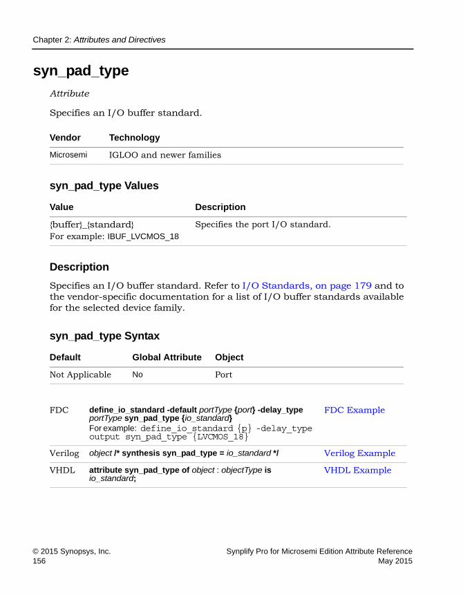
LO
Chapter 2: Attributes and Directives
© 2015 Synopsys, Inc. Synplify Pro for Microsemi Edition Attribute Reference156 May 2015
syn_pad_type
Attribute
Specifies an I/O buffer standard.
syn_pad_type Values
Description
Specifies an I/O buffer standard. Refer to I/O Standards, on page 179 and to the vendor-specific documentation for a list of I/O buffer standards available for the selected device family.
syn_pad_type Syntax
Vendor Technology
Microsemi IGLOO and newer families
Value Description
{buffer}_{standard}For example: IBUF_LVCMOS_18
Specifies the port I/O standard.
Default Global Attribute Object
Not Applicable No Port
FDC define_io_standard -default portType {port} -delay_type portType syn_pad_type {io_standard}For example: define_io_standard {p} -delay_type output syn_pad_type {LVCMOS_18}
FDC Example
Verilog object /* synthesis syn_pad_type = io_standard */ Verilog Example
VHDL attribute syn_pad_type of object : objectType is io_standard;
VHDL Example

Chapter 2: Attributes and Directives
Synplify Pro for Microsemi Edition Attribute Reference © 2015 Synopsys, Inc.May 2015 157
FDC Example
Constraint File Examples
-default_portType PortType can be input, output, or bidir. Setting default_input, default_output, or default_bidir causes all ports of that type to have the same I/0 standard applied to them.
-delay_type portType PortType can be input, output, or bidir.
syn_pad_type {io_standard} Specifies I/O standard (see following table).
To set ... Use this syntax ...
The default for all input ports to the AGP1X pad type
define_io_standard -default_input -delay_type input syn_pad_type {AGP1X}
All output ports to the GTL pad type
define_io_standard -default_output -delay_type output syn_pad_type {GTL}
All bidirectional ports to the CTT pad type
define_io_standard -default_bidir -delay_type bidir syn_pad_type {CTT}

LO
Chapter 2: Attributes and Directives
© 2015 Synopsys, Inc. Synplify Pro for Microsemi Edition Attribute Reference158 May 2015
The following are examples of pad types set on individual ports. You cannot assign pad types to bit slices.
define_io_standard {in1} -delay_type input syn_pad_type {LVCMOS_15}
define_io_standard {out21} -delay_type output syn_pad_type {LVCMOS_33}
define_io_standard {bidirbit} -delay_type bidir syn_pad_type {LVTTL_33}
Verilog Example
module top (clk,A,B,PC,P); input clk; input A ; input B,PC; output reg P/* synthesis syn_pad_type = "OBUF_LVCMOS_18" */; reg a_d,b_d; reg m; always @(posedge clk)
begin a_d <= A; b_d <= B; m <= a_d + b_d; P <= m + PC;
end endmodule
VHDL Example
library ieee; use ieee.std_logic_1164.all; use ieee.std_logic_unsigned.all; library synplify; use synplify.attributes.all; entity top is
port (clk : in std_logic; A : in std_logic_vector(1 downto 0);
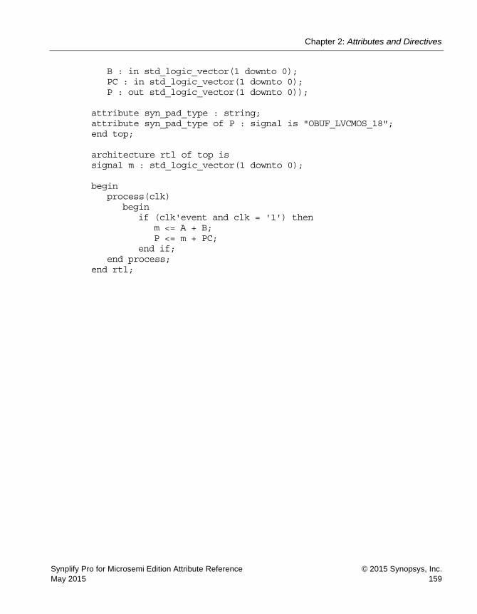
Chapter 2: Attributes and Directives
Synplify Pro for Microsemi Edition Attribute Reference © 2015 Synopsys, Inc.May 2015 159
B : in std_logic_vector(1 downto 0); PC : in std_logic_vector(1 downto 0); P : out std_logic_vector(1 downto 0));
attribute syn_pad_type : string; attribute syn_pad_type of P : signal is "OBUF_LVCMOS_18"; end top; architecture rtl of top is signal m : std_logic_vector(1 downto 0); begin
process(clk) begin
if (clk'event and clk = '1') then m <= A + B; P <= m + PC;
end if; end process;
end rtl;

LO
Chapter 2: Attributes and Directives
© 2015 Synopsys, Inc. Synplify Pro for Microsemi Edition Attribute Reference160 May 2015
Effect of Using syn_pad_type
The following figure shows the netlist output after the attribute is applied:
Verilog output reg P /*synthesis syn_pad_type = "OBUF_LVCMOS_18"*/;
VHDL attribute syn_pad_type of P : signal is "OBUF_LVCMOS_18";
Chapter 2: Attributes and Directives
Synplify Pro for Microsemi Edition Attribute Reference © 2015 Synopsys, Inc.May 2015 161
syn_preserve
Directive
Prevents sequential optimizations such as constant propagation, inverter push-through, and FSM extraction.
syn_preserve Values
Description
The syn_preserve directive controls whether objects are optimized away. Use syn_preserve to retain registers for simulation, or to preserve the logic of regis-ters driven by a constant 1 or 0. You can set syn_preserve on individual regis-ters or on the module/architecture so that the directive is applied to all regis-ters in the module.
For example, assume that the input of a flip-flop is always driven to the same value, such as logic 1. By default, the synthesis tool ties that signal to VCC and removes the flip-flop. Using syn_preserve on the registered signal prevents the removal of the flip-flop. This is useful when you are not finished with the design but want to do a preliminary run to find the area utilization.
Another use for this attribute is to preserve a particular state machine. When the FSM compiler is enabled, it performs various state-machine optimiza-tions. Use syn_preserve to retain a particular state machine and prevent it from being optimized away.
Technology Global Object
All Yes Register definition signal, module (Verilog)Output port or internal signal that holds the value of the register or architecture (VHDL)
Value Description
1 | true Preserves register logic.
0 | false (Default) Optimizes registers as needed.
LO
Chapter 2: Attributes and Directives
© 2015 Synopsys, Inc. Synplify Pro for Microsemi Edition Attribute Reference162 May 2015
When registers are removed during synthesis, the tool issues a warning message in the log file. For example:
@W:...Register bit out2 is always 0, optimizing ...
The syn_preserve directive is similar to syn_keep and syn_noprune, in that it preserves logic. For more information, see Comparison of syn_keep, syn_preserve, and syn_noprune, on page 110, and Preserving Objects from Being Optimized Away, on page 347 in the User Guide.
syn_preserve Syntax
Verilog Example
In the following example, syn_preserve is applied to all registers in the module to prevent them from being optimized away. For the results, see Effect of using syn_preserve, on page 164.
module mod_preserve (out1,out2,clk,in1,in2) /* synthesis syn_preserve=1 */;
output out1, out2; input clk; input in1, in2; reg out1; reg out2; reg reg1; reg reg2;
always@ (posedge clk)begin reg1 <= in1 &in2; reg2 <= in1&in2; out1 <= !reg1; out2 <= !reg1 & reg2; end endmodule
This is an example of setting syn_preserve on a state register:
reg [3:0] curstate /* synthesis syn_preserve = 1 */;
Verilog object /* synthesis syn_preserve = 0 |1 */ Verilog Example
VHDL attribute syn_preserve of object : objectType is true | false; VHDL Examples

Chapter 2: Attributes and Directives
Synplify Pro for Microsemi Edition Attribute Reference © 2015 Synopsys, Inc.May 2015 163
VHDL Examples
This section contains some VHDL code examples:
Example 1library ieee, synplify; use ieee.std_logic_1164.all;
entity simpledff is port (q : out std_logic_vector(7 downto 0);
d : in std_logic_vector(7 downto 0); clk : in std_logic);
-- Turn on flip-flop preservation for the q output attribute syn_preserve : boolean; attribute syn_preserve of q : signal is true; end simpledff;
architecture behavior of simpledff is begin
process(clk) begin
if rising_edge(clk) then -- Notice the continual assignment of "11111111" to q.
q <= (others => '1'); end if;
end process; end behavior;
Example 2In this example, syn_preserve is used on the signal curstate that is later used in a state machine to hold the value of the state register.
architecture behavior of mux is begin signal curstate : state_type; attribute syn_preserve of curstate : signal is true; -- Other code

LO
Chapter 2: Attributes and Directives
© 2015 Synopsys, Inc. Synplify Pro for Microsemi Edition Attribute Reference164 May 2015
Example 3The results for the following example are shown in Effect of using syn_preserve, on page 164.
library ieee; use ieee.std_logic_1164.all;
entity mod_preserve is port (out1 : out std_logic;
out2 : out std_logic; in1,in2,clk : in std_logic);
end mod_preserve;
architecture behave of mod_preserve is attribute syn_preserve : boolean; attribute syn_preserve of behave: architecture is true; signal reg1 : std_logic; signal reg2 : std_logic; begin
process begin
wait until clk'event and clk = '1'; reg1 <= in1 and in2; reg2 <= in1 and in2; out1 <= not (reg1); out2 <= (not (reg1) and reg2);
end process; end behave;
Effect of using syn_preserve
The following figure shows reg1 and out2 are preserved during optimization with syn_preserve.
When syn_preserve is not set, reg1 and reg2 are shared because they are driven by the same source. out2 gets the result of the AND of reg2 and NOT reg1. This is equivalent to the AND of reg1 and NOT reg1, which is a 0. As this is a constant, the tool removes out2 and the output out2 is always 0.
Verilog mod_preserve /* synthesis syn_preserve = 1 */
VHDL attribute syn_preserve of behave : architecture is true;

Chapter 2: Attributes and Directives
Synplify Pro for Microsemi Edition Attribute Reference © 2015 Synopsys, Inc.May 2015 165
With syn_preserve
Without syn_preserve

LO
Chapter 2: Attributes and Directives
© 2015 Synopsys, Inc. Synplify Pro for Microsemi Edition Attribute Reference166 May 2015
syn_probe
Attribute
Inserts probe points for testing and debugging the internal signals of a design.
syn_probe Values
Description
syn_probe works as a debugging aid, inserting probe points for testing and debugging the internal signals of a design. The probes appear as ports at the top level. When you use this attribute, the tool also applies syn_keep to the net.
You can specify values to name probe ports and assign pins to named ports for selected technologies. Pin-locking properties of probed nets will be trans-ferred to the probe port and pad. If empty square brackets [] are used, probe names will be automatically indexed, according to the index of the bus being probed.
The table below shows how to apply syn_probe values to nets, buses, and bus slices. It indicates what port names will appear at the top level. When the syn_probe value is 0, probe generation is disabled; when syn_probe is 1, the probe port name is derived from the net name.
Value Description
1/true Inserts a probe, and automatically derives a name for the probe port from the net name.
0/false Disables probe generation.
portName Inserts a probe and generates a port with the specified name. If you include empty square brackets, [ ], the probe names are automatically indexed to the net name.
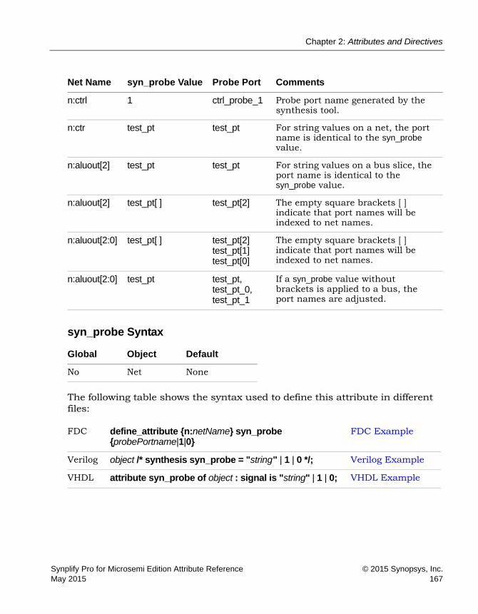
Chapter 2: Attributes and Directives
Synplify Pro for Microsemi Edition Attribute Reference © 2015 Synopsys, Inc.May 2015 167
syn_probe Syntax
The following table shows the syntax used to define this attribute in different files:
Net Name syn_probe Value Probe Port Comments
n:ctrl 1 ctrl_probe_1 Probe port name generated by the synthesis tool.
n:ctr test_pt test_pt For string values on a net, the port name is identical to the syn_probe value.
n:aluout[2] test_pt test_pt For string values on a bus slice, the port name is identical to the syn_probe value.
n:aluout[2] test_pt[ ] test_pt[2] The empty square brackets [ ] indicate that port names will be indexed to net names.
n:aluout[2:0] test_pt[ ] test_pt[2] test_pt[1] test_pt[0]
The empty square brackets [ ] indicate that port names will be indexed to net names.
n:aluout[2:0] test_pt test_pt, test_pt_0, test_pt_1
If a syn_probe value without brackets is applied to a bus, the port names are adjusted.
Global Object Default
No Net None
FDC define_attribute {n:netName} syn_probe {probePortname|1|0}
FDC Example
Verilog object /* synthesis syn_probe = "string " | 1 | 0 */; Verilog Example
VHDL attribute syn_probe of object : signal is "string" | 1 | 0; VHDL Example

LO
Chapter 2: Attributes and Directives
© 2015 Synopsys, Inc. Synplify Pro for Microsemi Edition Attribute Reference168 May 2015
FDC Example
The following examples insert a probe signal into a net and assign pin locations to the ports.
define_attribute {n:inst2.DATA0_*[7]} syn_probe {test_pt[]} define_attribute {n:inst2.DATA0_*[7]} syn_loc
{14,12,11,5,21,18,16,15}
Verilog Example
The following example inserts probes on bus alu_tmp [7:0] and assigns pin locations to each of the ports inserted for the probes.
module alu(out1, opcode, clk, a, b, sel); output [7:0] out1; input [2:0] opcode; input [7:0] a, b; input clk, sel; reg [7:0] alu_tmp /* synthesis syn_probe="alu1_probe[]"
syn_loc="A5,A6,A7,A8,A10,A11,A13,A14" */; reg [7:0] out1; // Other code always @(opcode or a or b or sel) begin
case (opcode) 3'b000:alu_tmp <= a+b; 3'b000:alu_tmp <= a-b; 3'b000:alu_tmp <= a^b; 3'b000:alu_tmp <= sel ? a:b; default:alu_tmp <= a|b;
endcase end
always @(posedge clk) out1 <= alu_tmp; endmodule

Chapter 2: Attributes and Directives
Synplify Pro for Microsemi Edition Attribute Reference © 2015 Synopsys, Inc.May 2015 169
VHDL Example
The following example inserts probes on bus alu_tmp(7 downto 0) and assigns pin locations to each of the ports inserted for the probes.
library ieee; use ieee.std_logic_1164.all; entity alu is port (a : in std_logic_vector(7 downto 0);
b : in std_logic_vector(7 downto 0); opcode : in std_logic_vector(2 downto 0);
clk : in std_logic; out1 : out std_logic_vector(7 downto 0));
end alu; architecture rtl of alu is signal alu_tmp : std_logic_vector (7 downto 0);
attribute syn_probe : string; attribute syn_probe of alu_tmp : signal is "test_pt"; attribute syn_loc : string; attribute syn_loc of alu_tmp : signal is
"A5,A6,A7,A8,A10,A11,A13,A14";
begin
process (clk) begin
if (clk'event and clk = '1') then out1 <= alu_tmp; end if;
end process; process (opcode,a,b)
begin case opcode is when "000" => alu_tmp <= a and b; when "001" => alu_tmp <= a or b; when "010" => alu_tmp <= a xor b; when "011" => alu_tmp <= a nand b; when others => alu_tmp <= a nor b;
end case; end process;
end rtl;

LO
Chapter 2: Attributes and Directives
© 2015 Synopsys, Inc. Synplify Pro for Microsemi Edition Attribute Reference170 May 2015
Effect of Using syn_probe
Before applying syn_probe:
After applying syn_probe with 1:
Verilog reg [7:0] alu_tmp /* synthesis syn_probe="0"*/
VHDL attribute syn_probe of alu_tmp : signal is "0";
Verilog reg [7:0] alu_tmp /* synthesis syn_probe="1"*/
VHDL attribute syn_probe of alu_tmp : signal is "1";

Chapter 2: Attributes and Directives
Synplify Pro for Microsemi Edition Attribute Reference © 2015 Synopsys, Inc.May 2015 171
After applying syn_probe with test_pt:
Verilog reg [7:0] alu_tmp /* synthesis syn_probe="test_pt"*/
VHDL attribute syn_probe of alu_tmp : signal is "test_pt";

LO
Chapter 2: Attributes and Directives
© 2015 Synopsys, Inc. Synplify Pro for Microsemi Edition Attribute Reference172 May 2015
After applying syn_probe with test_pt[]:
Verilog reg [7:0] alu_tmp /* synthesis syn_probe="test_pt[]"*/
VHDL attribute syn_probe of alu_tmp : signal is "test_pt[]";

Chapter 2: Attributes and Directives
Synplify Pro for Microsemi Edition Attribute Reference © 2015 Synopsys, Inc.May 2015 173

LO
Chapter 2: Attributes and Directives
© 2015 Synopsys, Inc. Synplify Pro for Microsemi Edition Attribute Reference174 May 2015
syn_radhardlevel
Attribute
Implements designs with high reliability, using radiation-resistant techniques.
syn_radhardlevel for Microsemi
Some high reliability techniques are not available or appropriate for all Microsemi families. Use a design technique that is valid for the project. Contact Microsemi technical support for details.
You can apply syn_radhardlevel globally to the top-level module/architecture or on an individual register output signal (or inferred register in VHDL), and the tool uses the attribute value in conjunction with the Microsemi macro files supplied with the software. For more details about using this attribute, see Specifying syn_radhardlevel in the Source Code, on page 494 and Working with Radhard Designs, on page 493 in the User Guide.
syn_radhardlevel Values (Microsemi)
Vendor Technologies
Microsemi ProASIC3, ProASIC3E, ProASIC3L
none DefaultUses standard design techniques, and does not insert any triple register logic.
tmr Microsemi ProASIC3, ProASIC3E, ProASIC3L Uses triple module redundancy or triple voting to implement registers. Each register is implemented by three flip-flops or latches that “vote” to determine the state of the register. This option can potentially affect area and timing QoR because of the additional logic inserted, so be sure to check your area and timing goals when you use this option.
Chapter 2: Attributes and Directives
Synplify Pro for Microsemi Edition Attribute Reference © 2015 Synopsys, Inc.May 2015 175
syn_radhardlevel Syntax (Microsemi)
The following table summarizes the syntax in different files:
Constraint File Exampledefine_attribute {dataout[3:0]} syn_radhardlevel {tmr}
Verilog syn_radhardlevel Example//Top level module top (clk, dataout, a, b); input clk; input a; input b; output [3:0] dataout; M1 inst_M1 (a1, M3_out1, clk, rst, M1_out); // Other code
//Sub modules subjected to DTMR module M1 (a1, a2, clk, rst, q)
/* synthesis syn_radhardlevel="distributed_tmr" */; input clk; input signed [15:0] a1,a2; input clk, rst; output signed [31:0] q; // Other code
Name Global Attribute Object
syn_radhardlevel No Module, architecture, register Verilog: output signal VHDL: architecture, signal
FDC define_attribute {object} syn_radhardlevel {none|tmr} Constraint File Example
Verilog object /* synthesis syn_radhardlevel = none|tmr */ Verilog syn_radhardlevel Example
VHDL attribute syn_rardhardlevel : boolean; attribute syn_radhardlevel of object : object type is none|tmr;
VHDL syn_radhardlevel Example
LO
Chapter 2: Attributes and Directives
© 2015 Synopsys, Inc. Synplify Pro for Microsemi Edition Attribute Reference176 May 2015
VHDL syn_radhardlevel ExampleSee VHDL Attribute and Directive Syntax, on page 574 for alternate methods for specifying VHDL attributes and directives.
library synplify; architecture top of top is attribute syn_radhardlevel : string; attribute syn_radhardlevel of top: architecture is "tmr"; -- Other code

Chapter 2: Attributes and Directives
Synplify Pro for Microsemi Edition Attribute Reference © 2015 Synopsys, Inc.May 2015 177
syn_ramstyle
Attribute
Specifies the implementation for an inferred RAM.
syn_ramstyle Values
The values for syn_ramstyle vary with the target technology. The following table lists all the valid syn_ramstyle values, some of which apply only to certain technologies. For details about using syn_ramstyle, see RAM Attributes, on page 321 in the User Guide.
Vendor Devices
Microsemi ProASIC3, Fusion, SmartFusion2
Default Global Attribute Object
block_ram Yes View, module, entity, RAM instance
block_ram Specifies that the inferred RAM be mapped to the appropriate device-specific memory. It uses the dedicated memory resources in the FPGA. By default, the software uses deep block RAM configurations instead of wide configurations to get better timing results. Using deeper RAMs reduces the output data delay timing by reducing the MUX logic at the output of the RAMs. By default the software does not use the parity bit for data with this option. Alternatively, you can specify a ramType value. See RAM Type Values and Implementations, on page 178 for details of how memory is implemented for different devices.
no_rw_check By default, the synthesis tool inserts bypass logic around the inferred RAM to avoid simulation mismatches caused by indeterminate output values when reads and writes are made to the same address. When this option is specified, the synthesis tool does not insert glue logic around the RAM. You cannot use it with the rw_check option, as the two are mutually exclusive. There are other read-write check controls. See Read-Write Address Checks, on page 179 for details about the differences.

LO
Chapter 2: Attributes and Directives
© 2015 Synopsys, Inc. Synplify Pro for Microsemi Edition Attribute Reference178 May 2015
RAM Type Values and ImplementationsThe table lists vendor-specify RAM implementation information, including vendor-specific ramType values.
ramType Specifies a device-specific RAM implementation. Valid values for Microsemi include: lsram, uram
See RAM Type Values and Implementations, on page 178 for details of how memory is implemented for different devices.
registers Specifies that an inferred RAM be mapped to registers (flip-flops and logic), not technology-specific RAM resources.
rw_check When enabled, the synthesis tool inserts bypass logic around the RAM to prevent a simulation mismatch between the RTL and post-synthesis simulations. You cannot use it with the no_rw_check option, as the two are mutually exclusive. There are other read-write check controls. See Read-Write Address Checks, on page 179 for details about the differences.
Vendor Values Implementation Technology
Microsemi Default: block_ram ProASIC3/ ProASIC3E/ ProASIC3Lregisters Registers
Default: Registers SmartFusion, Fusion IGLOO+, IGLOO IGLOOe
lsram RAM1K18 SmartFusion2
uram RAM64X18
registers Registers

Chapter 2: Attributes and Directives
Synplify Pro for Microsemi Edition Attribute Reference © 2015 Synopsys, Inc.May 2015 179
Description
The syn_ramstyle attribute specifies the implementation to use for an inferred RAM. You can apply the attribute globally, to a module, or a RAM instance. You can also use syn_ramstyle to prevent the inference of a RAM, by setting it to registers. If your RAM resources are limited, you can map additional RAMs to registers instead of RAM resources using this setting.
The syn_ramstyle values vary with the technology.
Read-Write Address ChecksWhen reads and writes are made to the same address, the output could be indeterminate, and this can cause simulation mismatches. By default, the synthesis tool inserts bypass logic around an inferred RAM to avoid these mismatches. The synthesis tool offers multiple ways to specify how to handle read-write address checking:
If there is a conflict, the software uses the following order of precedence:
• syn_ramstyle attribute settings
• syn_rw_conflict_logic attribute
• Read Write Check on RAM option on the Device panel of the Implementation Options dialog box.
Read Write Control Use when ...
syn_ramstyle You know your design does not read and write to the same address simultaneously and you want to specify the RAM implementation. The attribute has two mutually-exclusive read-write check options: • Use no_rw_check to eliminate bypass logic. If you enable
global RAM inference with the Read Write Check on RAM option, you can use no_rw_check to selectively disable glue logic insertion for individual RAMs.
• Use rw_check to insert bypass logic. If you disable global RAM inference with the Read Write Check on RAM option, you can use rw_check to selectively enable glue logic insertion for individual RAMs.
Read Write Check on RAM You want to globally enable or disable glue logic insertion for all the RAMs in the design.

LO
Chapter 2: Attributes and Directives
© 2015 Synopsys, Inc. Synplify Pro for Microsemi Edition Attribute Reference180 May 2015
syn_ramstyle Syntax
FDC Example
If you edit a constraint file to apply syn_ramstyle, be sure to include the range of the signal with the signal name. For example:
define_attribute {mem[7:0]} syn_ramstyle {registers};
define_attribute {mem[7:0]} syn_ramstyle {block_ram};
Verilog Example
module RAMB4_S4 (data_out, ADDR, data_in, EN, CLK, WE, RST); output[3:0] data_out; input [7:0] ADDR; input [3:0] data_in; input EN, CLK, WE, RST; reg [3:0] mem [255:0] /* synthesis syn_ramstyle="block_ram" */; reg [3:0] data_out;
always@(posedge CLK) if(EN)
if(RST == 1) data_out <= 0;
else begin
if(WE == 1) data_out <= data_in;
else data_out <= mem[ADDR];
end
FDC define_attribute {signalname [bitRange]} -syn_ramstyle valuedefine_global_attribute syn_ramstyle value
FDC Example
Verilog object /* synthesis syn_ramstyle = value */ Verilog Example
VHDL attribute syn_ramstyle of object : objectType is value ; VHDL Example

Chapter 2: Attributes and Directives
Synplify Pro for Microsemi Edition Attribute Reference © 2015 Synopsys, Inc.May 2015 181
always @(posedge CLK) if (EN && WE) mem[ADDR] = data_in; endmodule
VHDL Example
library ieee; use ieee.std_logic_1164.all; USE ieee.numeric_std.ALL; library synplify;
entity RAMB4_S4 is port (ADDR: in std_logic_vector(7 downto 0);
data_in : in std_logic_vector(3 downto 0); WE : in std_logic; CLK : in std_logic; RST : in std_logic; EN : in std_logic; data_out : out std_logic_vector(3 downto 0));
end RAMB4_S4;
architecture rtl of RAMB4_S4 is type mem_type is array (255 downto 0) of std_logic_vector (3 downto 0); signal mem : mem_type; -- mem is the signal that defines the RAM attribute syn_ramstyle : string; attribute syn_ramstyle of mem : signal is "block_ram";
begin process (CLK) begin IF (CLK'event AND CLK = '1') THEN
IF (EN = '1') THEN IF (RST = '1') THEN
data_out <= "0000"; ELSE
IF (WE = '1') THEN data_out <= data_in;
ELSE data_out <= mem(to_integer(unsigned(ADDR)));
END IF; END IF;
END IF; END IF; end process;

LO
Chapter 2: Attributes and Directives
© 2015 Synopsys, Inc. Synplify Pro for Microsemi Edition Attribute Reference182 May 2015
process (CLK) begin IF (CLK'event AND CLK = '1') THEN
IF (EN = '1' AND WE = '1') THEN mem(to_integer(unsigned(ADDR))) <= data_in;
END IF; END IF; end process;
end rtl;

Chapter 2: Attributes and Directives
Synplify Pro for Microsemi Edition Attribute Reference © 2015 Synopsys, Inc.May 2015 183
syn_reference_clock
Attribute
Specifies a clock frequency other than the one implied by the signal on the clock pin of the register.
Description
syn_reference_clock is a way to change clock frequencies other than using the signal on the clock pin. For example, when flip-flops have an enable with a regular pattern, such as every second clock cycle, use syn_reference_clock to have timing analysis treat the flip-flops as if they were connected to a clock at half the frequency.
To use syn_reference_clock, define a new clock, then apply its name to the registers you want to change.
FDC Example
define_attribute {register} syn_reference_clock {clockName}
For example:
define_attribute {myreg[31:0]} syn_reference_clock {sloClock}
You can also use syn_reference_clock to constrain multiple-cycle paths through the enable signal. Assign the find command to a collection (clock_enable_col), then refer to the collection when applying the syn_reference_clock constraint.
The following example shows how you can apply the constraint to all registers with the enable signal en40:
define_scope_collection clock_enable_col {find -seq * -filter (@clock_enable==en40)}
define_attribute {$clock_enable_col} syn_reference_clock {clk2}
Vendor Technology Default Value Global Object
Microsemi SmartFusion2, ProASIC3 - - Register
FDC define_attribute {register} syn_reference_clock {clockName}
FDC Example

LO
Chapter 2: Attributes and Directives
© 2015 Synopsys, Inc. Synplify Pro for Microsemi Edition Attribute Reference184 May 2015
Note: You apply syn_reference_clock only in a constraint file; you cannot use it in source code.
Effect of using syn_reference_clock
The following figure shows the report before applying the attribute:
This is the report after applying the attribute:

Chapter 2: Attributes and Directives
Synplify Pro for Microsemi Edition Attribute Reference © 2015 Synopsys, Inc.May 2015 185
syn_replicate
Attribute
Controls replication of registers during optimization.
syn_replicate values
Description
The synthesis tool automatically replicates registers while optimizing the design and fixing fanouts, packing I/Os, or improving the quality of results.
If area is a concern, you can use this attribute to disable replication either globally or on a per-register basis. When you disable replication globally, it disables I/O packing and other QoR optimizations. When it is disabled, the synthesis tool uses only buffering to meet maximum fanout guidelines.
To disable I/O packing on specific registers, set the attribute to 0. Similarly, you can use it on a register between clock boundaries to prevent replication. Take an example where the tool replicates a register that is clocked by clk1 but whose fanin cone is driven by clk2, even though clk2 is an unrelated clock in another clock group. By setting the attribute for the register to 0, you can disable this replication.
syn_replicate Syntax Specification
Vendor Technologies
Microsemi SmartFusion and older families
Value Default Global Object Description
0 No Yes Register Disables duplication of registers
1 Yes Yes Register Allows duplication of registers
FDC define_global_attribute syn_replicate {0 | 1}; FDC Example
Verilog object /* synthesis syn_replicate = 1 | 0 */; Verilog Example
VHDL attribute syn_replicate : boolean;attribute syn_replicate of object : signal is true|false;
VHDL Example

LO
Chapter 2: Attributes and Directives
© 2015 Synopsys, Inc. Synplify Pro for Microsemi Edition Attribute Reference186 May 2015
FDC Example
Verilog Example
module norep (Reset, Clk, Drive, OK, ADPad, IPad, ADOut); input Reset, Clk, Drive, OK; input [6:0] ADOut; inout [6:0] ADPad; output [6:0] IPad; reg [6:0] IPad; reg DriveA /* synthesis syn_replicate = 0 */; assign ADPad = DriveA ? ADOut : 32'bz;
always @(posedge Clk or negedge Reset) if (!Reset)
begin DriveA <= 0; IPad <= 0;
end else
begin DriveA <= Drive & OK; IPad <= ADPad;
end endmodule

Chapter 2: Attributes and Directives
Synplify Pro for Microsemi Edition Attribute Reference © 2015 Synopsys, Inc.May 2015 187
VHDL Example
library IEEE; use ieee.std_logic_1164.all;
entity norep is port (Reset : in std_logic;
Clk : in std_logic; Drive : in std_logic; OK : in std_logic; ADPad : inout std_logic_vector (6 downto 0); IPad : out std_logic_vector (6 downto 0); ADOut : in std_logic_vector (6 downto 0) );
end norep;
architecture archnorep of norep is signal DriveA : std_logic; attribute syn_replicate : boolean; attribute syn_replicate of DriveA : signal is false; begin ADPad <= ADOut when DriveA='1' else (others => 'Z');
process (Clk, Reset) begin
if Reset='0' then DriveA <= '0'; IPad <= (others => '0');
elsif rising_edge(clk) then DriveA <= Drive and OK; IPad <= ADPad;
end if; end process;
end archnorep;
Effect of Using syn_replicate
The following example shows a design without the syn_replicate attribute:
Verilog reg DriveA /*synthesis syn_replicate=1*/
VHDL attribute syn_replicate : boolean;attribute syn_replicate of DriveA : signal is true;
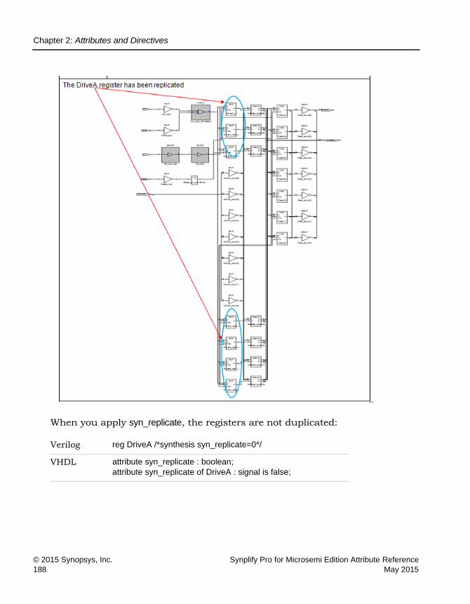
LO
Chapter 2: Attributes and Directives
© 2015 Synopsys, Inc. Synplify Pro for Microsemi Edition Attribute Reference188 May 2015
When you apply syn_replicate, the registers are not duplicated:
Verilog reg DriveA /*synthesis syn_replicate=0*/
VHDL attribute syn_replicate : boolean;attribute syn_replicate of DriveA : signal is false;

Chapter 2: Attributes and Directives
Synplify Pro for Microsemi Edition Attribute Reference © 2015 Synopsys, Inc.May 2015 189

LO
Chapter 2: Attributes and Directives
© 2015 Synopsys, Inc. Synplify Pro for Microsemi Edition Attribute Reference190 May 2015
syn_resources
Attribute
Specifies the resources used inside a black box.
syn_resources Values
The value for this attribute can be specified with any combination of the following:
Description
Specifies the resources used inside a black box. This attribute is applied to Verilog black-box modules and VHDL architectures or component definitions.
syn_resources Syntax
The following table summarizes the syntax in different files.
Vendor Technology
Microsemi ProASIC3, IGLOO, Fusion, and SmartFusion families
Global Support Object
No Module or architecture
Value Description
blockrams=integer Number of RAM resources
corecells=integer Number of core cells

Chapter 2: Attributes and Directives
Synplify Pro for Microsemi Edition Attribute Reference © 2015 Synopsys, Inc.May 2015 191
FDC Example
You can apply the attribute to more than one kind of resource at a time by separating assignments with a comma (,). For example:
define_attribute {v:bb} syn_resources {corecells=300, blockrams=5}
Example – Verilog syn_resources (Microsemi)In Verilog, you can only attach this attribute to a module. Here is the example,
FDC define_attribute {v:moduleName} syn_resources {corecells=integer | blockrams=integer}
FDC Example
Verilog object /* synthesis syn_resources = value */; Example – Verilog syn_resources (Microsemi)
VHDL attribute syn_resources : string; attribute syn_resources of object : objectType is value;
Example – VHDL syn_resources (Microsemi)

LO
Chapter 2: Attributes and Directives
© 2015 Synopsys, Inc. Synplify Pro for Microsemi Edition Attribute Reference192 May 2015
Example – VHDL syn_resources (Microsemi)In VHDL, this attribute can be placed on either an architecture or a compo-nent declaration.
Effect of Using syn_resources (Microsemi)
You can check the Resource Utilization report in the log file to verify how resources are actually mapped.

syn_safe_case Chapter 2: Attributes and Directives
Synplify Pro for Microsemi Edition Attribute Reference © 2015 Synopsys, Inc.May 2015 193
syn_safe_case
Directive Synplify Pro
This directive enables/disables the safe case option.
syn_safe_case Values
Description
This directive enables/disables the safe case option. When enabled, the high reliability safe case option turns off sequential optimizations for counters, FSM, and sequential logic to increase the reliability of the circuit. If you set this directive on a module or architecture, the module or architecture is treated as safe and all case statements within it are implemented as safe. For more information, see Specifying Safe FSMs, on page 316
syn_safe_case Syntax
Verilog Example
For example:
module top (input a, output b) /* synthesis syn_safe_case =1 */
Vendor Technologies
Microsemi
Value Description Default Global
false Turns off the safe case option. false No
true Turns on the safe case option.
FDC define_attribute {object} syn_safe_case {true | false}
Verilog module /* syn_safe_case = "1 | 0" */; Verilog Example
VHDL attribute syn_safe_case : boolean;attribute syn_safe_case of architectureName: architecture is "true | false";
VHDL Example

LO
Chapter 2: Attributes and Directives syn_safe_case
© 2015 Synopsys, Inc. Synplify Pro for Microsemi Edition Attribute Reference194 May 2015
VHDL Example
For example:
library ieee; use ieee.std_logic_1164.all; entity test is port (a input std_logic;
b: out std_logic); end test; architecture rtl of test is attribute syn_safe_case: boolean; attribute syn_safe_case of rtl : architecture is "TRUE";

syn_sharing Chapter 2: Attributes and Directives
Synplify Pro for Microsemi Edition Attribute Reference © 2015 Synopsys, Inc.May 2015 195
syn_sharing
Directive
Enables or disables the sharing of operator resources during the compilation stage of synthesis.
syn_sharing Values
Description
The syn_sharing directive controls resource sharing during the compilation stage of synthesis. This is a compiler-specific optimization that does not affect the mapper; this means that the mapper might still perform resource sharing optimizations to improve timing, even if syn_sharing is disabled.
You can also specify global resource sharing with the Resource Sharing option in the Project view, from the Project->Implementation Options->Options panel, or with the set_option -resource_sharing Tcl command.
If you disable resource sharing globally, you can use the syn_sharing directive to turn on resource sharing for specific modules or architectures. See Sharing Resources, on page 356 in the User Guide for a detailed procedure.
syn_sharing Syntax
Technology Default Value Global Object
All On Yes Component, module
Value Description
off | false Does not share resources during the compilation stage of synthesis.
on | true(Default)
Optimizes the design to perform resource sharing during the compilation stage of synthesis.
Verilog object /* synthesis syn_sharing=”on | off” */; Verilog Example
VHDL attribute syn_sharing of object : objectType is “true | false”; VHDL Example

LO
Chapter 2: Attributes and Directives syn_sharing
© 2015 Synopsys, Inc. Synplify Pro for Microsemi Edition Attribute Reference196 May 2015
Verilog Example
module add (a, b, x, y, out1, out2, sel, en, clk) /* synthesis syn_sharing=off */;
input a, b, x, y, sel, en, clk; output out1, out2; wire tmp1, tmp2; assign tmp1 = a * b; assign tmp2 = x * y; reg out1, out2;
always@(posedge clk) if (en)
begin out1 <= sel ? tmp1: tmp2;
end else
begin out2 <= sel ? tmp1: tmp2;
end endmodule

syn_sharing Chapter 2: Attributes and Directives
Synplify Pro for Microsemi Edition Attribute Reference © 2015 Synopsys, Inc.May 2015 197
VHDL Example
library ieee; use ieee.std_logic_1164.all; use ieee.std_logic_unsigned.all; entity add is
port (a, b : in std_logic_vector(1 downto 0); x, y : in std_logic_vector(1 downto 0); clk, sel, en: in std_logic; out1 : out std_logic_vector(3 downto 0); out2 : out std_logic_vector(3 downto 0)
); end add; architecture rtl of add is
attribute syn_sharing : string; attribute syn_sharing of rtl: architecture is "true";
signal tmp1, tmp2: std_logic_vector(3 downto 0); begin
tmp1 <= a * b; tmp2 <= x * y;
process(clk) begin if clk'event and clk='1' then
if (en='1') then if (sel='1') then
out1 <= tmp1; else
out1 <= tmp2; end if;
else if (sel='1') then out2 <= tmp1;
else out2 <= tmp2; end if;
end if; end if;
end process; end rtl;
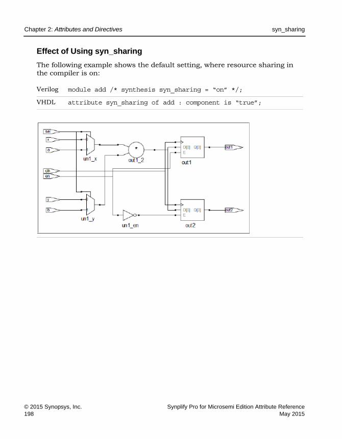
LO
Chapter 2: Attributes and Directives syn_sharing
© 2015 Synopsys, Inc. Synplify Pro for Microsemi Edition Attribute Reference198 May 2015
Effect of Using syn_sharing
The following example shows the default setting, where resource sharing in the compiler is on:
Verilog module add /* synthesis syn_sharing = “on” */;
VHDL attribute syn_sharing of add : component is “true”;

syn_sharing Chapter 2: Attributes and Directives
Synplify Pro for Microsemi Edition Attribute Reference © 2015 Synopsys, Inc.May 2015 199
The next figure shows the same design when resource sharing is off, and two adders are inferred:
Verilog module add /* synthesis syn_sharing = “off” */;
VHDL attribute syn_sharing of add : component is “false”;

LO
Chapter 2: Attributes and Directives syn_shift_resetphase
© 2015 Synopsys, Inc. Synplify Pro for Microsemi Edition Attribute Reference200 May 2015
syn_shift_resetphase
Attribute
Allows you to remove the flip-flop on the inactive clock edge, built by the reset recovery logic for an FSM when a single event upset (SEU) fault occurs.
syn_shift_resetphase Values
Description
When a single event upset (SEU) fault occurs, the FSM can transition to an unreachable state. The syn_encoding attribute with a value of safe provides a mechanism to build additional logic for recovery to the specified reset state. For an FSM with asynchronous reset, the software inserts an additional flip-flop to the recovery logic path on the opposite edge of the design clock, isolating the reset. You can use the syn_shift_resetphase attribute to remove this additional flip-flop on the inactive clock edge, if necessary.
For more information about the syn_encoding attribute, see syn_encoding, on page 54.
syn_shift_resetphase Syntax
Vendor Technology
Microsemi SmartFusion/2, RT ProASIC3, ProASIC3/3E/3L, IGLOO/+/E/2
Value Description
1(Default)
The flip-flop on the inactive clock edge is present.
0 Removes the flip-flop on the inactive clock edge.
Global Support Object
Yes FSM instance

syn_shift_resetphase Chapter 2: Attributes and Directives
Synplify Pro for Microsemi Edition Attribute Reference © 2015 Synopsys, Inc.May 2015 201
The following table summarizes the syntax in different files:
SCOPE Example
The Tcl equivalent is shown below:
define_attribute {i:present_state[11:0]}{syn_shift_resetphase}{0}
Verilog Example
Apply the syn_shift_resetphase attribute on the top module or state register as shown in the Verilog code segment below.
module test (clk, rst, in, out) /* synthesis syn_shift_resetphase = 0 */;
... reg [3:0] present_state
/* synthesis syn_shift_resetphase = 0 */, next_state; ... endmodule
VHDL Example
Here is a VHDL code segment showing how to use the syn_shift_resetphase attribute.
entity fsm is ... end fsm;
FDC define_attribute object {syn_shift_resetphase} {1|0|}define_global_attribute {syn_shift_resetphase} {1|0}
SCOPE Example
Verilog object /* synthesis syn_shift_resetphase = ”1 | 0” */; Verilog Example
VHDL attribute syn_shift_resetphase of state : signal is “true | false”; VHDL Example

LO
Chapter 2: Attributes and Directives syn_shift_resetphase
© 2015 Synopsys, Inc. Synplify Pro for Microsemi Edition Attribute Reference202 May 2015
architecture rtl of fsm is signal present_state : std_logic_vector(3 downto 0); -- Specifying on the architecture attribute syn_shift_resetphase : boolean; attribute syn_shift_resetphase of rtl : architecture is false; -- Specifying on the state signal attribute syn_shift_resetphase : boolean; attribute syn_shift_resetphase of present_state : signal is false; begin ... end rtl;
Effect of Using syn_shift_resetphase
Safe encoding is implemented for the following state machine.
This example shows Technology view results before the syn_shift_resetphase attribute is applied.

syn_shift_resetphase Chapter 2: Attributes and Directives
Synplify Pro for Microsemi Edition Attribute Reference © 2015 Synopsys, Inc.May 2015 203
This example shows Technology view results after the syn_shift_resetphase attribute is applied.
LO
Chapter 2: Attributes and Directives syn_state_machine
© 2015 Synopsys, Inc. Synplify Pro for Microsemi Edition Attribute Reference204 May 2015
syn_state_machine
Directive
Enables/disables state-machine optimization on individual state registers in the design.
syn_state_machine Values
Description
Enables/disables state-machine optimization on individual state registers in the design. When you disable the FSM Compiler, state-machines are not automatically extracted. To extract some state machines, use this directive with a value of 1 on just those individual state-registers to be extracted. Conversely, when the FSM Compiler is enabled and there are state machines in your design that you do not want extracted, use syn_state_machine with a value of 0 to override extraction on just those individual state registers.
Also, when the FSM Compiler is enabled, all state machines are usually detected during synthesis. However, on occasion there are cases in which certain state machines are not detected. You can use this directive to declare those undetected registers as state machines.
syn_state_machine Syntax
Technology Default Value Global Object
All Default is determined by the global FSM Compiler option.set_option -symbolic_fsm_compiler 1
Yes Component, module
Value Description
off | false Does not extract state machines automatically.
on | true Automatically extracts state machines.
Verilog object /* synthesis syn_state_machine = ”0 | 1” */; Example – Verilog syn_state_machine
VHDL attribute syn_state_machine of state : signal is “false | true”; Example – VHDL syn_state_machine

syn_state_machine Chapter 2: Attributes and Directives
Synplify Pro for Microsemi Edition Attribute Reference © 2015 Synopsys, Inc.May 2015 205
For Verilog:
• object is a state register.
• Data type is Boolean: 0 does not extract an FSM, 1 extracts an FSM.
reg [7:0] current_state /* synthesis syn_state_machine=1 */;
For VHDL:
• state is a signal that holds the value of the state machine.
• Data type is Boolean: false does not extract an FSM, true extracts an FSM.
attribute syn_state_machine of current_state: signal is true;
Example – Verilog syn_state_machine
This is the Verilog source code used for the example in the following figure.
Example – VHDL syn_state_machine
This is the VHDL source code used for the example in the following figure.
Effect of Using syn_state_machine
The following figure shows an example of two implementations of a state machine: one with the syn_state_machine directive enabled, the other with the directive disabled.

LO
Chapter 2: Attributes and Directives syn_state_machine
© 2015 Synopsys, Inc. Synplify Pro for Microsemi Edition Attribute Reference206 May 2015
See the following HDL syntax and example sections for the source code used to generate the schematics above. See also:
• syn_encoding, on page 54 for information on overriding default encoding styles for state machines.
• For VHDL designs, syn_encoding Compared to syn_enum_encoding, on page 65 for usage information about these two directives.
syn_state_machine=0
syn_state_machine=1

syn_tco<n> Chapter 2: Attributes and Directives
Synplify Pro for Microsemi Edition Attribute Reference © 2015 Synopsys, Inc.May 2015 207
syn_tco<n>
Directive
Supplies the clock to output timing-delay through a black box.
Description
Used with the syn_black_box directive; supplies the clock to output timing-delay through a black box.
The syn_tco<n> directive is one of several directives that you can use with the syn_black_box directive to define timing for a black box. See syn_black_box, on page 47 for a list of the associated directives.
syn_tco<n> Syntax
The syn_tco<n> directive can be entered as an attribute using the Attributes panel of the SCOPE editor. The information in the Object, Attribute, and Value fields must be manually entered. This is the constraint file syntax for the directive:
define_attribute {v:blackboxModule} syn_tcon {[!]clock->bundle=value}
For details about the syntax, see the following table:
Verilog object /* syn_tcon = " [!]clock -> bundle = value " */;
VHDL attribute syn_tcon of object : objectType is " [!]clock -> bundle = value";
v: Constraint file syntax that indicates the directive is attached to the view.
blackboxModule The symbol name of the black-box.
n A numerical suffix that lets you specify different clock to output timing delays for multiple signals/bundles.
! The optional exclamation mark indicates that the clock is active on its falling (negative) edge.
clock The name of the clock signal.

LO
Chapter 2: Attributes and Directives syn_tco<n>
© 2015 Synopsys, Inc. Synplify Pro for Microsemi Edition Attribute Reference208 May 2015
Constraint file example:
define_attribute {v:work.test} {syn_tsu4} {clk->tout=1.0}
Verilog Example
object /* syn_tcon = " [!]clock -> bundle = value " */;
See syn_tco<n> Syntax, on page 207 for syntax explanations. The following example defines syn_tco<n> and other black-box constraints:
module test(myclk, a, b, tout,) /*synthesis syn_black_box syn_tco1="clk->tout=1.0"
syn_tpd1="b->tout=8.0" syn_tsu1="a->myclk=2.0" */; input myclk; input a, b; output tout; endmodule
//Top Level module top (input clk, input a, b, output fout); test U1 (clk, a, b, fout); endmodule
VHDL Example
In VHDL, there are ten predefined instances of each of these directives in the synplify library: syn_tco1, syn_tco2, syn_tco3, … syn_tco10. If you are entering the timing directives in the source code and you require more than 10 different timing delay values for any one of the directives, declare the additional direc-tives with an integer greater than 10. For example:
attribute syn_tco11 : string; attribute syn_tco12 : string;
bundle A bundle is a collection of buses and scalar signals. The objects of a bundle must be separated by commas with no intervening spaces. A valid bundle is A,B,C, which lists three signals. To assign values to bundles, use the following syntax:
[!]clock->bundle=value
The values are in ns.
value Clock to output delay value in ns.

syn_tco<n> Chapter 2: Attributes and Directives
Synplify Pro for Microsemi Edition Attribute Reference © 2015 Synopsys, Inc.May 2015 209
See syn_tco<n> Syntax, on page 207 for other syntax explanations.
See VHDL Attribute and Directive Syntax, on page 574 for alternate methods for specifying VHDL attributes and directives.
The following example defines syn_tco<n> and other black-box constraints:
library ieee; use ieee.std_logic_1164.all; use ieee.std_logic_unsigned.all; entity test is generic (size: integer := 8); port (tout : out std_logic_vector (size- 1 downto 0);
a : in std_logic_vector (size- 1 downto 0); b : in std_logic_vector (size- 1 downto 0);
myclk : in std_logic);
attribute syn_isclock : boolean; attribute syn_isclock of myclk: signal is true; end; architecture rtl of test is attribute syn_black_box : boolean; attribute syn_black_box of rtl: architecture is true; begin end; -- TOP Level-- library ieee; use ieee.std_logic_1164.all; use ieee.std_logic_unsigned.all; entity top is generic (size: integer: = 8); port (fout : out std_logic_vector(size- 1 downto 0);
a : in std_logic_vector (size- 1 downto 0); b : in std_logic_vector (size- 1 downto 0);
clk : in std_logic );
end; architecture rtl of top is component test generic (size: integer := 8); port (tout : out std_logic_vector(size- 1 downto 0);
a : in std_logic_vector (size- 1 downto 0); b : in std_logic_vector (size- 1 downto 0);
myclk : in std_logic

LO
Chapter 2: Attributes and Directives syn_tco<n>
© 2015 Synopsys, Inc. Synplify Pro for Microsemi Edition Attribute Reference210 May 2015
); end component; attribute syn_tco1 : string; attribute syn_tco1 of test : component is
"clk->tout = 1.0"; attribute syn_tpd1 : string; attribute syn_tpd1 of test : component is
"b->tout= 2.0"; attribute syn_tsu1 : string; attribute syn_tsu1 of test : component is
"a-> myclk = 1.2"; begin U1 : test port map(fout, a, b, clk); end;
Verilog-Style Syntax in VHDL for Black Box TimingIn addition to the syntax used in the code above, you can also use the following Verilog-style syntax to specify black-box timing constraints:
attribute syn_tco1 of inputfifo_coregen : component is "rd_clk->dout[48:0]=3.0";

syn_tco<n> Chapter 2: Attributes and Directives
Synplify Pro for Microsemi Edition Attribute Reference © 2015 Synopsys, Inc.May 2015 211
Effect of using syn_tco
This figure shows the HDL Analyst Technology view before using syn_tco:
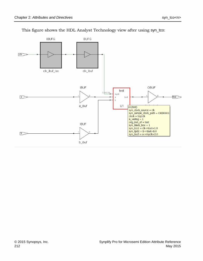
LO
Chapter 2: Attributes and Directives syn_tco<n>
© 2015 Synopsys, Inc. Synplify Pro for Microsemi Edition Attribute Reference212 May 2015
This figure shows the HDL Analyst Technology view after using syn_tco:

syn_tpd<n> Chapter 2: Attributes and Directives
Synplify Pro for Microsemi Edition Attribute Reference © 2015 Synopsys, Inc.May 2015 213
syn_tpd<n>
Directive
Supplies information on timing propagation for combinational delays through a black box.
Description
Used with the syn_black_box directive; supplies information on timing propa-gation for combinational delay through a black box.
The syn_tpd<n> directive is one of several directives that you can use with the syn_black_box directive to define timing for a black box. See syn_black_box, on page 47 for a list of the associated directives.
syn_tpd<n> Syntax
You can enter the syn_tpd<n> directive as an attribute using the Attributes panel of the SCOPE editor. The information in the Object, Attribute, and Value fields must be manually entered. This is the constraint file syntax:
define_attribute {v:blackboxModule} syn_tpdn {bundle->bundle=value}
For details about the syntax, see the following table:
Verilog object /* syn_tpdn = " bundle -> bundle = value " */;
VHDL attribute syn_tpdn of object : objectType is " bundle -> bundle = value";
v: Constraint file syntax that indicates the directive is attached to the view.
blackboxModule The symbol name of the black-box.

LO
Chapter 2: Attributes and Directives syn_tpd<n>
© 2015 Synopsys, Inc. Synplify Pro for Microsemi Edition Attribute Reference214 May 2015
Constraint file example:
define_attribute {v:MEM} syn_tpd1 {MEM_RD->DATA_OUT[63:0]=20}
Verilog Example
See syn_tpd<n> Syntax, on page 213 for an explanation of the syntax. This is an example of syn_tpd<n> along with some of the other black-box timing constraints:
module test(myclk, a, b, tout,) /*synthesis syn_black_box syn_tco1="clk->tout=1.0"
syn_tpd1="b->tout=8.0" syn_tsu1="a->myclk=2.0" */; input myclk; input a, b; output tout; endmodule
//Top Level module top(input clk, input a, b, output fout); test U1 (clk, a, b, fout); endmodule
n A numerical suffix that lets you specify different input to output timing delays for multiple signals/bundles.
bundle A bundle is a collection of buses and scalar signals. The objects of a bundle must be separated by commas with no intervening spaces. A valid bundle is A,B,C, which lists three signals.
"bundle->bundle=value"
The values are in ns.
value Input to output delay value in ns.

syn_tpd<n> Chapter 2: Attributes and Directives
Synplify Pro for Microsemi Edition Attribute Reference © 2015 Synopsys, Inc.May 2015 215
VHDL Example
In VHDL, there are 10 predefined instances of each of these directives in the synplify library, for example: syn_tpd1, syn_tpd2, syn_tpd3, … syn_tpd10. If you are entering the timing directives in the source code and you require more than 10 different timing delay values for any one of the directives, declare the additional directives with an integer greater than 10. For example:
attribute syn_tpd11 : string; attribute syn_tpd11 of bitreg : component is
"di0,di1 -> do0,do1 = 2.0"; attribute syn_tpd12 : string; attribute syn_tpd12 of bitreg : component is
"di2,di3 -> do2,do3 = 1.8";
See syn_tpd<n> Syntax, on page 213 for an explanation of the syntax.
See VHDL Attribute and Directive Syntax, on page 574 for different ways to specify VHDL attributes and directives.
The following is an example of assigning syn_tpd<n> along with some of the black box constraints. See Verilog-Style Syntax in VHDL for Black Box Timing, on page 210 for another way.
library ieee; use ieee.std_logic_1164.all; use ieee.std_logic_unsigned.all; entity test is generic (size: integer := 8); port (tout : out std_logic_vector(size- 1 downto 0);
a : in std_logic_vector (size- 1 downto 0); b : in std_logic_vector (size- 1 downto 0);
myclk : in std_logic); attribute syn_isclock : boolean; attribute syn_isclock of myclk: signal is true; end; architecture rtl of test is attribute syn_black_box : boolean; attribute syn_black_box of rtl: architecture is true; begin end;

LO
Chapter 2: Attributes and Directives syn_tpd<n>
© 2015 Synopsys, Inc. Synplify Pro for Microsemi Edition Attribute Reference216 May 2015
-- TOP Level-- library ieee; use ieee.std_logic_1164.all; use ieee.std_logic_unsigned.all; entity top is generic (size: integer := 8); port (fout : out std_logic_vector(size- 1 downto 0);
a : in std_logic_vector (size- 1 downto 0); b : in std_logic_vector (size- 1 downto 0); clk : in std_logic );
end;
architecture rtl of top is component test generic (size: integer := 8); port (tout : out std_logic_vector(size- 1 downto 0);
a : in std_logic_vector (size- 1 downto 0); b : in std_logic_vector (size- 1 downto 0); myclk : in std_logic );
end component; attribute syn_tco1 : string; attribute syn_tco1 of test : component is
"clk->tout = 1.0"; attribute syn_tpd1 : string; attribute syn_tpd1 of test : component is
"b->tout= 2.0"; attribute syn_tsu1 : string; attribute syn_tsu1 of test : component is
"a-> myclk = 1.2"; begin U1 : test port map(fout, a, b, clk); end;

syn_tpd<n> Chapter 2: Attributes and Directives
Synplify Pro for Microsemi Edition Attribute Reference © 2015 Synopsys, Inc.May 2015 217
Effect of using syn_tpd
This figure shows the HDL Analyst Technology view before using syn_tpd:

LO
Chapter 2: Attributes and Directives syn_tpd<n>
© 2015 Synopsys, Inc. Synplify Pro for Microsemi Edition Attribute Reference218 May 2015
After using syn_tpdThis figure shows the HDL Analyst Technology view after using syn_tpd:

syn_tristate Chapter 2: Attributes and Directives
Synplify Pro for Microsemi Edition Attribute Reference © 2015 Synopsys, Inc.May 2015 219
syn_tristate
Directive
Specifies that an output port on a black box is a tristate.
syn_tristate Values
Description
You can use this directive to specify that an output port on a module defined as a black box is a tristate. This directive eliminates multiple driver errors if the output of a black box has more than one driver. A multiple driver error is issued unless you use this directive to specify that the outputs are tristate.
syn_tristate Syntax
Verilog Example
module test(myclk, a, b, tout) /* synthesis syn_black_box */; input myclk; input a, b; output tout/* synthesis syn_tristate = 1 */; endmodule //Top Level module top(input [1:0]en, input clk, input a, b, output reg fout); wire tmp; assign tmp = en[0] ? (a & b) : 1'bz; assign tmp = en[1] ? (a | b) : 1'bz; always@(posedge clk)
Value Default
0 Yes
1
Verilog object /* synthesis syn_tristate = 1 */;
VHDL attribute syn_tristate : boolean;
attribute syn_tristate of tout: signal is true;
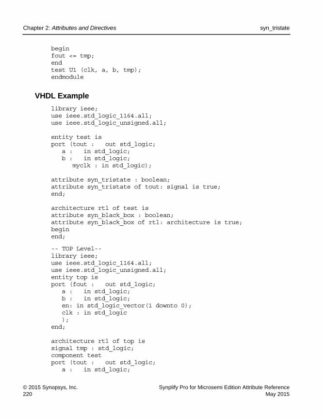
LO
Chapter 2: Attributes and Directives syn_tristate
© 2015 Synopsys, Inc. Synplify Pro for Microsemi Edition Attribute Reference220 May 2015
begin fout <= tmp; end test U1 (clk, a, b, tmp); endmodule
VHDL Example
library ieee; use ieee.std_logic_1164.all; use ieee.std_logic_unsigned.all; entity test is port (tout : out std_logic;
a : in std_logic; b : in std_logic;
myclk : in std_logic); attribute syn_tristate : boolean; attribute syn_tristate of tout: signal is true; end; architecture rtl of test is attribute syn_black_box : boolean; attribute syn_black_box of rtl: architecture is true; begin end;
-- TOP Level-- library ieee; use ieee.std_logic_1164.all; use ieee.std_logic_unsigned.all; entity top is port (fout : out std_logic;
a : in std_logic; b : in std_logic; en: in std_logic_vector(1 downto 0); clk : in std_logic );
end; architecture rtl of top is signal tmp : std_logic; component test port (tout : out std_logic;
a : in std_logic;

syn_tristate Chapter 2: Attributes and Directives
Synplify Pro for Microsemi Edition Attribute Reference © 2015 Synopsys, Inc.May 2015 221
b : in std_logic; myclk : in std_logic
); end component; begin tmp <= (a and b)when en(0) = '1' else 'Z'; tmp <= (a or b) when en(1) = '1' else 'Z'; process (clk) begin
if (clk = '1' and clk'event) then fout <= tmp;
end if; end process; U1 : test port map(fout, a, b, clk); end;

LO
Chapter 2: Attributes and Directives syn_tsu<n>
© 2015 Synopsys, Inc. Synplify Pro for Microsemi Edition Attribute Reference222 May 2015
syn_tsu<n>
Directive
Sets information on timing setup delay required for input pins in a black box.
Description
Used with the syn_black_box directive; supplies information on timing setup delay required for input pins (relative to the clock) in the black box.
The syn_tsu<n> directive is one of several directives that you can use with the syn_black_box directive to define timing for a black box. See syn_black_box, on page 47 for a list of the associated directives.
syn_tsu<n> Syntax
The syn_tsu<n> directive can be entered as an attribute using the Attributes panel of the SCOPE editor. The information in the Object, Attribute, and Value fields must be manually entered. The constraint file syntax for the directive is:
define_attribute {v:blackboxModule} syn_tsun {bundle-> [!]clock=value}
For details about the syntax, see the following table:
Verilog object /* syn_tsun = "bundle -> [!]clock = value " */;
VHDL attribute syn_tsun of object : objectType is "bundle -> [!]clock = value ";
v: Constraint file syntax that indicates the directive is attached to the view.
blackboxModule The symbol name of the black-box.
n A numerical suffix that lets you specify different clock to output timing delays for multiple signals/bundles.
bundle A collection of buses and scalar signals. The objects of a bundle must be separated by commas with no intervening spaces. A valid bundle is A,B,C, which lists three signals. The values are in ns. This is the syntax to define a bundle:
bundle->[!]clock=value

syn_tsu<n> Chapter 2: Attributes and Directives
Synplify Pro for Microsemi Edition Attribute Reference © 2015 Synopsys, Inc.May 2015 223
Constraint file example:
define_attribute {v:RTRV_MOD} syn_tsu4 {RTRV_DATA[63:0]->!CLK=20}
Verilog Example
For syntax explanations, see syn_tsu<n> Syntax, on page 222.
This is an example that defines syn_tsu<n> along with some of the other black-box constraints:
module test(myclk, a, b, tout,) /*synthesis syn_black_box syn_tco1="clk->tout=1.0" syn_tpd1="b->tout=8.0" syn_tsu1="a->myclk=2.0" */; input myclk; input a, b; output tout; endmodule
//Top Level module top (input clk, input a, b, output fout); test U1 (clk, a, b, fout); endmodule
VHDL Examples
In VHDL, there are 10 predefined instances of each of these directives in the synplify library, for example: syn_tsu1, syn_tsu2, syn_tsu3, … syn_tsu10. If you are entering the timing directives in the source code and you require more than 10 different timing delay values for any one of the directives, declare the additional directives with an integer greater than 10:
attribute syn_tsu11 : string; attribute syn_tsu11 of bitreg : component is
"di0,di1 -> clk = 2.0"; attribute syn_tsu12 : string; attribute syn_tsu12 of bitreg : component is
"di2,di3 -> clk = 1.8";
! The optional exclamation mark indicates that the clock is active on its falling (negative) edge.
clock The name of the clock signal.
value Input to clock setup delay value in ns.

LO
Chapter 2: Attributes and Directives syn_tsu<n>
© 2015 Synopsys, Inc. Synplify Pro for Microsemi Edition Attribute Reference224 May 2015
For other syntax explanations, see syn_tsu<n> Syntax, on page 222.
See VHDL Attribute and Directive Syntax, on page 574 for different ways to specify VHDL attributes and directives. For this directive, you can also use the following Verilog-style syntax to specify it, as described in Verilog-Style Syntax in VHDL for Black Box Timing, on page 210.
The following is an example of assigning syn_tsu<n> along with some of the other black-box constraints:
library ieee; use ieee.std_logic_1164.all; use ieee.std_logic_unsigned.all; entity test is generic (size: integer := 8); port (tout : out std_logic_vector(size- 1 downto 0);
a : in std_logic_vector (size- 1 downto 0); b : in std_logic_vector (size- 1 downto 0);
myclk : in std_logic); attribute syn_isclock : boolean; attribute syn_isclock of myclk: signal is true; end; architecture rtl of test is attribute syn_black_box : boolean; attribute syn_black_box of rtl: architecture is true; begin end;
-- TOP Level-- library ieee; use ieee.std_logic_1164.all; use ieee.std_logic_unsigned.all; entity top is generic (size: integer := 8); port (fout : out std_logic_vector (size- 1 downto 0);
a : in std_logic_vector (size- 1 downto 0); b : in std_logic_vector (size- 1 downto 0); clk : in std_logic );
end; architecture rtl of top is component test

syn_tsu<n> Chapter 2: Attributes and Directives
Synplify Pro for Microsemi Edition Attribute Reference © 2015 Synopsys, Inc.May 2015 225
generic (size: integer := 8); port (tout : out std_logic_vector(size- 1 downto 0);
a : in std_logic_vector (size- 1 downto 0); b : in std_logic_vector (size- 1 downto 0);
myclk : in std_logic );
end component; attribute syn_tco1 : string; attribute syn_tco1 of test : component is
"clk->tout = 1.0"; attribute syn_tpd1 : string; attribute syn_tpd1 of test : component is
"b->tout= 2.0"; attribute syn_tsu1 : string; attribute syn_tsu1 of test : component is
"a-> myclk = 1.2"; begin U1 : test port map (fout, a, b, clk); end;
Effect of using syn_tsu
This figure shows the HDL Analyst Technology view before using syn_tsu:

LO
Chapter 2: Attributes and Directives syn_tsu<n>
© 2015 Synopsys, Inc. Synplify Pro for Microsemi Edition Attribute Reference226 May 2015
This figure shows the HDL Analyst Technology view after using syn_tsu:

translate_off/translate_on Chapter 2: Attributes and Directives
Synplify Pro for Microsemi Edition Attribute Reference © 2015 Synopsys, Inc.May 2015 227
translate_off/translate_on
Directive
Synthesizes designs originally written for use with other synthesis tools without needing to modify source code.
Description
Allows you to synthesize designs originally written for use with other synthesis tools without needing to modify source code. All source code that is between these two directives is ignored during synthesis.
Another use of these directives is to prevent the synthesis of stimulus source code that only has meaning for logic simulation. You can use translate_off/translate_on to skip over simulation-specific lines of code that are not synthesizable.
When you use translate_off in a module, synthesis of all source code that follows is halted until translate_on is encountered. Every translate_off must have a corresponding translate_on. These directives cannot be nested, therefore, the translate_off directive can only be followed by a translate_on directive.
See also, pragma translate_off/pragma translate_on, on page 40. These direc-tives are implemented the same in the source code.
translate_off/translate_on Syntax
Verilog Example
module test(input a, b, output dout, Nout); assign dout = a + b;
//Anything between pragma translate_off/translate_on is ignored by the synthesis tool hence only
//the adder circuit above is implemented not the multiplier circuit below:
Verilog /* synthesis translate_off */
/* synthesis translate_on */
VHDL synthesis translate_off
synthesis translate_on

LO
Chapter 2: Attributes and Directives translate_off/translate_on
© 2015 Synopsys, Inc. Synplify Pro for Microsemi Edition Attribute Reference228 May 2015
/* synthesis translate_off */ assign Nout = a * b; /* synthesis translate_on */
endmodule
For SystemVerilog designs, you can alternatively use the synthesis_off/synthesis_on directives. The directives function the same as the translate_off/translate_on directives to ignore all source code contained between the two directives during synthesis.
For Verilog designs, you can use the synthesis macro with the Verilog ‘ifdef directive instead of the translate on/off directives. See synthesis Macro, on page 372 for information.
VHDL Example
For VHDL designs, you can alternatively use the synthesis_off/synthesis_on directives. Select Project->Implementation Options->VHDL and enable the Synthesis On/Off Implemented as Translate On/Off option. This directs the compiler to treat the synthesis_off/on directives like translate_off/on and ignore any code between these directives.
See VHDL Attribute and Directive Syntax, on page 574 for different ways to specify VHDL attributes and directives.
library ieee; use ieee.std_logic_1164.all; use ieee.std_logic_unsigned.all;
entity test is port
a : in std_logic_vector(1 downto 0); b : in std_logic_vector(1 downto 0); dout : out std_logic_vector(1 downto 0); Nout : out std_logic_vector(3 downto 0) );
end;
architecture rtl of test is begin
dout <= a + b; --Anything between pragma translate_off/translate_on is ignored
by the synthesis tool hence only --the adder circuit above is implemented not the multiplier circuit

translate_off/translate_on Chapter 2: Attributes and Directives
Synplify Pro for Microsemi Edition Attribute Reference © 2015 Synopsys, Inc.May 2015 229
below: --pragma translate_off
Nout <= a * b; --pragma translate_on end;
Effects of Using translate_off/translate_on
Here is the RTL view before applying the attribute.
This is the RTL view after applying the attribute.

LO
Chapter 2: Attributes and Directives translate_off/translate_on
© 2015 Synopsys, Inc. Synplify Pro for Microsemi Edition Attribute Reference230 May 2015

Synplify Pro for Microsemi Edition Attribute Reference © 2015 Synopsys, Inc.May 2015
A P P E N D I X C
Example Code
This appendix contains the code samples that are referenced by the corresponding chapter.
VHDL Example 3: Component Declaration
library ieee; use ieee.std_logic_1164.all; entity sub is port (a, b, c, d : in std_logic; x,y : out std_logic); end sub; architecture behave of sub is attribute syn_hier : string; attribute syn_hier of behave : architecture is “hard”; begin x <= a and b; y <= c and d; end behave; --Top level library ieee; use ieee.std_logic_1164.all; entity top is port (a1, b1 : in std_logic; c1,d1,clk : in std_logic; y1 :out std_logic); end;
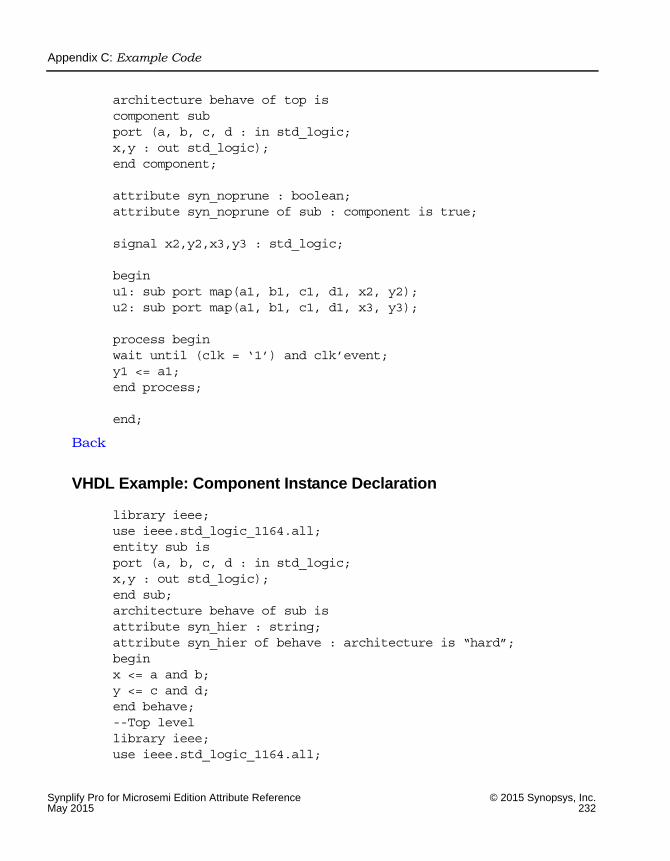
LO
Appendix C: Example Code
Synplify Pro for Microsemi Edition Attribute Reference © 2015 Synopsys, Inc.May 2015 232
architecture behave of top is component sub port (a, b, c, d : in std_logic; x,y : out std_logic); end component; attribute syn_noprune : boolean; attribute syn_noprune of sub : component is true; signal x2,y2,x3,y3 : std_logic; begin u1: sub port map(a1, b1, c1, d1, x2, y2); u2: sub port map(a1, b1, c1, d1, x3, y3); process begin wait until (clk = ‘1’) and clk’event; y1 <= a1; end process; end;
Back
VHDL Example: Component Instance Declaration
library ieee; use ieee.std_logic_1164.all; entity sub is port (a, b, c, d : in std_logic; x,y : out std_logic); end sub; architecture behave of sub is attribute syn_hier : string; attribute syn_hier of behave : architecture is “hard”; begin x <= a and b; y <= c and d; end behave; --Top level library ieee; use ieee.std_logic_1164.all;

Appendix C: Example Code
Synplify Pro for Microsemi Edition Attribute Reference © 2015 Synopsys, Inc.May 2015 233
entity top is port (a1, b1 : in std_logic; c1,d1,clk : in std_logic; y1 :out std_logic); end; architecture behave of top is component sub port (a, b, c, d : in std_logic; x,y : out std_logic); end component; signal x2,y2,x3,y3 : std_logic; attribute syn_noprune : boolean; attribute syn_noprune of u1 : label is true; begin u1: sub port map(a1, b1, c1, d1, x2, y2); --Instance with syn_noprune directive u2: sub port map(a1, b1, c1, d1, x3, y3); process begin wait until (clk = ‘1’) and clk’event; y1 <= a1; end process; end;
Back
VHDL Example 4: Black Box
--Top level library ieee; use ieee.std_logic_1164.all; entity top is port (a1, b1 : in std_logic; c1,d1,clk : in std_logic; y1 :out std_logic); end; architecture behave of top is component sub port (a, b, c, d : in std_logic; x,y : out std_logic); end component; attribute syn_noprune : boolean;

LO
Appendix C: Example Code
Synplify Pro for Microsemi Edition Attribute Reference © 2015 Synopsys, Inc.May 2015 234
attribute syn_noprune of sub : component is true; signal x2,y2,x3,y3 : std_logic; begin u1: sub port map(a1, b1, c1, d1, x2, y2); u2: sub port map(a1, b1, c1, d1, x3, y3); process begin wait until (clk = ‘1’) and clk’event; y1 <= a1; end process; end;
Back
Verilog Example 1 -- Module Declaration
//Top module module top (input int a, b, output int c); assign c=b; sub i1 (a); endmodule //Intermediate sub level which does not specify syn_noprune module sub (input int a); leaf i2 (a,); endmodule //Leaf level with syn_noprune directive module leaf (input int a, output int b) /* synthesis syn_noprune=1*/; assign b = a; endmodule
Back
Verilog Example 2: Hierarchical Design
//Leaf level module module sub1 (data, rst, dout); parameter width = 1; input [width :0] data; input rst;

Appendix C: Example Code
Synplify Pro for Microsemi Edition Attribute Reference © 2015 Synopsys, Inc.May 2015 235
output [width : 0] dout; assign dout = rst?1’b0:data; endmodule //Intermediate Top level with 3 instances of sub1 module top (data1,data2,data3, rst, dout1); parameter width1 = 2; parameter width2 = 3; parameter width3 = 4; input [width1 :0] data1; input [width2 :0] data2; input [width3 :0] data3; input rst; output [width1 : 0] dout1; sub1 #(width1) inst1 (data1,rst,dout1); sub1 #(width2) inst2 (data2,rst,) /* synthesis syn_noprune=1 */; sub1 #(width3) inst3 (data3,rst,); endmodule //Top level module top1 (data1,data2,data3, rst, dout1); parameter width1 = 2; parameter width2 = 3; parameter width3 = 4; input [width1 :0] data1; input [width2 :0] data2; input [width3 :0] data3; input rst; output [width1 : 0] dout1; top #(width1, width2, width3) top (data1,data2,data3, rst, dout1); endmodule
Back
Example: Verilog syn_resources (Microsemi)
module bb (o,i) /* synthesis syn_black_box syn_resources = “corecells=300, blockrams=10” */; input i; output o; endmodule module top_bb (o,i); input i;

LO
Appendix C: Example Code
Synplify Pro for Microsemi Edition Attribute Reference © 2015 Synopsys, Inc.May 2015 236
output o; bb u1 (o,i); endmodule
Back
Example: VHDL syn_resources (Microsemi)
library ieee; use ieee.std_logic_1164.all; entity top is port (o : out std_logic; i : in std_logic ); end top; architecture top_rtl of top is component bb port (o : out std_logic; i : in std_logic); end component; begin U1: bb port map(o, i); end top_rtl; --black box entity library ieee; use ieee.std_logic_1164.all; entity bb is port (o : out std_logic; i : in std_logic ); end bb; architecture rtl of bb is

Appendix C: Example Code
Synplify Pro for Microsemi Edition Attribute Reference © 2015 Synopsys, Inc.May 2015 237
attribute syn_resources : string; attribute syn_resources of rtl: architecture is “corecells=300, blockrams=10”; begin end rtl;
Back
Example: Verilog syn_state_machine
module FSM1 (clk, in1, rst, out1); input clk, rst, in1; output [2:0] out1; `define s0 3’b000 `define s1 3’b001 `define s2 3’b010 `define s3 3’bxxx reg [2:0] out1; reg [2:0] state /* xsynthesis syn_state_machine = 1 */; reg [2:0] next_state; always @(posedge clk or posedge rst) if (rst) state <= `s0; else state <= next_state; // Combined Next State and Output Logic always @(state or in1) case (state) `s0 : begin out1 <= 3’b000; if (in1) next_state <= `s1; else next_state <= `s0; end `s1 : begin out1 <= 3’b001; if (in1) next_state <= `s2; else next_state <= `s1; end `s2 : begin out1 <= 3’b010; if (in1) next_state <= `s3;

LO
Appendix C: Example Code
Synplify Pro for Microsemi Edition Attribute Reference © 2015 Synopsys, Inc.May 2015 238
else next_state <= `s2; end default : begin out1 <= 3’bxxx; next_state <= `s0; end endcase endmodule
Back
Example: VHDL syn_state_machine
library ieee; use ieee.std_logic_1164.all; entity FSM1 is port (clk,rst,in1 : in std_logic; out1 : out std_logic_vector (2 downto 0)); end FSM1; architecture behave of FSM1 is type state_values is (s0, s1, s2,s3); signal state, next_state: state_values; attribute syn_state_machine : boolean; attribute syn_state_machine of state : signal is false; begin process (clk, rst) begin if rst = ‘1’ then state <= s0; elsif rising_edge(clk) then state <= next_state; end if; end process; process (state, in1) begin case state is when s0 => out1 <= “000”; if in1 = ‘1’ then next_state <= s1; else next_state <= s0; end if; when s1 => out1 <= “001”;

Appendix C: Example Code
Synplify Pro for Microsemi Edition Attribute Reference © 2015 Synopsys, Inc.May 2015 239
if in1 = ‘1’ then next_state <= s2; else next_state <= s1; end if; when s2 => out1 <= “010”; if in1 = ‘1’ then next_state <= s3; else next_state <= s2; end if; when others => out1 <= “XXX”; next_state <= s0; end case; end process; end behave;
Back

LO
Appendix C: Example Code
Synplify Pro for Microsemi Edition Attribute Reference © 2015 Synopsys, Inc.May 2015 240
Synplify Pro for Microsemi Edition Attribute Reference, May 2015 241
Index
Aalsloc 15alspin 18alspreserve 21attributes
custom 64global attribute summary 11specifying in the SCOPE spreadsheet 8specifying, overview of methods 8
Attributes panel, SCOPE spreadsheet 8
Bblack box directives
black_box_pad_pin 24black_box_tri_pins 29syn_black_box 47syn_isclock 104syn_resources 190syn_tco 207syn_tpd 213syn_tristate 219syn_tsu 222
black boxesdirectives. See black box directivessource code directives 48timing directives 213
black_box_pad_pin directive 24black_box_tri_pins directive 29buffers
clock. See clock buffersglobal. See global buffers
Ccase statement
default 34clock buffers
assigning resources 140clocks
on black boxes 104code
ignoring with pragma translate off/on 40
compilerloop iteration, loop_limit 36loop iteration, syn_looplimit 117
custom attributes 64
Ddefine_attribute
syntax 9define_false_path
using with syn_keep 108define_global_attribute
summary 11syntax 9
define_multicycle_pathusing with syn_keep 108
Eedif file
scalar and array ports 136syn_noarrayports attribute 136
enumerated typessyn_enum_encoding directive 63
Ffanout limits
overriding default 119syn_maxfan attribute 119
FSMssyn_encoding attribute 54
full_case directive 32
Gglobal attributes summary 11global buffers

Index
242 Synplify Pro for Microsemi Edition Attribute Reference, May 2015
defining 69
Hhierarchy
flattening with syn_hier 76high reliability
syn_radhardlevel 174
II/O buffers
inserting 100specifying I/O standards 156
I/O packingdisabling with syn_replicate 185
instancespreserving with syn_noprune 146
Lloop_limit directive 36
MMicrosemi
alsloc attribute 15alspin attribute 18alspreserve attribute 21assigning I/O ports 18preserving relative placement 15syn_radhardlevel attribute 174
multicycle pathssyn_reference_clock 183
Nnets
preserving with syn_keep 108
Ppad locations
See also pin locationsparallel_case directive 38pin locations
forward annotating 114Microsemi 18
pragma translate_off directive 40pragma translate_on directive 40priority encoding 38
probesinserting 166
RRAMs
implementation styles 177technology support 178
registerspreserving with syn_preserve 161
relative locationalsloc (Microsemi) 15
replicationdisabling 185
resource sharingsyn_sharing directive 195
retimingsyn_allow_retiming attribute 43
SSCOPE spreadsheet
Attributes panel 8sequential optimization, preventing with
syn_preserve 161simulation mismatches
full_case directive 35state machines
enumerated types 63extracting 204
syn_allow_retiming attribute 43syn_black_box directive 47syn_encoding
compared with syn_enum_encoding directive 65
using with enum_encoding 64syn_encoding attribute 54syn_enum_encoding
using with enum_encoding 64syn_enum_encoding directive 63
compared with syn_encoding attribute 65
syn_global_buffers attribute 69syn_hier
using with fanout guides 119syn_hier attribute 76syn_insert_buffer attribute 94syn_insert_pad attribute 100syn_isclock directive 104

Index
Synplify Pro for Microsemi Edition Attribute Reference, May 2015 243
syn_keepcompared with syn_preserve and
syn_noprune directives 110syn_keep directive 108syn_loc attribute 114syn_looplimit directive 117syn_maxfan attribute 119syn_multstyle attribute 125syn_netlist_hierarchy attribute 130syn_noarrayports attribute 136syn_noclockbuf attribute 140
using with fanout guides 120syn_noprune directive 146syn_pad_type attribute 156syn_preserve
compared with syn_keep and syn_noprune 162
syn_preserve directive 161syn_probe attribute 166syn_radhardlevel 174
Microsemi options 174Microsemi syntax 175TMR. See TMR, distributed TMR
syn_ramstyle attribute 177syn_reference_clock attribute 183syn_replicate
using with fanout guides 120syn_replicate attribute 185syn_resources attribute 190syn_safe_case directive 193syn_sharing directive 195syn_shift_resetphase 200syn_state_machine directive 204syn_tco directive 207syn_tpd directive 213
black-box timing 213, 222syn_tristate directive 219syn_tsu directive 222
black-box timing 222synthesis_off directive 228synthesis_on directive 228SystemVerilog
ignoring code with synthesis_off/on 228SystemVerilog data types
assignment for syn_keep 109
Ttiming
syn_tco directive 207syn_tpd directive 213syn_tsu directive 222
TMRMicrosemi syn_radhardlevel 174
translate_off directive 227translate_on directive 227tristates
black_box_tri_pins directive 29syn_tristate directive 219
VVerilog
ignoring code with translate off/on 227syn_keep on multiple nets 109
Wwires, preserving with syn_keep directive 108

Index
244 Synplify Pro for Microsemi Edition Attribute Reference, May 2015