swivel suit inflator valve - frogkick.nl...4 swivel suit inflator valve maintenance manual 5 swivel...
TRANSCRIPT

SWIVEL SUIT INFLATOR VALVE
APEKS MARINE EQUIPMENT LTD, NEPTUNE WAY, BLACKBURN, LANCASHIRE. BB1 2BTTel: 0044 (0) 1254 692200 Fax: 0044 (0) 1254 692211 E-mail: [email protected] Web: www.apeks.co.uk
TECHNICAL SUPPORT
MAINTENANCE MANUAL FOR
AUTHORISED TECHNICIANS
Document No. AP 5926Issue 110/01/06
2
Swivel Suit Inflator Valve Maintenance Manual
3
Swivel Suit Inflator Valve Maintenance Manual
ContentsCOPYRIGHT NOTICE............................................................................................................................................... 3
INTRODUCTION....................................................................................................................................................... 3
WARNINGS, CAUTIONS & NOTES ......................................................................................................................... 3
SCHEDULED SERVICE............................................................................................................................................ 3
GENERAL GUIDELINES.......................................................................................................................................... 3
GENERAL CONVENTIONS...................................................................................................................................... 4
DISASSEMBLY PROCEDURES............................................................................................................................... 4
REASSEMBLY PROCEDURES................................................................................................................................ 5
TESTING PROCEDURES......................................................................................................................................... 6
TABLE 1 - TROUBLSHOOTING GUIDE................................................................................................................... 7
TABLE 2 - RECOMMENDED TOOL LIST ................................................................................................................ 7
TABLE 3 - RECOMMENDED LUBRICANTS AND CLEANERS............................................................................. 8
CLEANING AND LUBRICATION PROCEDURE...................................................................................................... 9
TABLE 4 -TORQUE SPECIFICATIONS.................................................................................................................. 10
TABLE 5 - TEST BENCH SPECIFICATIONS ......................................................................................................... 10
EXPLODED PARTS DRAWING............................................................................................................................. 11
2
Swivel Suit Inflator Valve Maintenance Manual
3
Swivel Suit Inflator Valve Maintenance Manual
COPYRIGHT NOTICEThis manual is copyrighted, all rights reserved. It may not, in whole or in part, be copied, photocopied, reproduced or translated without prior consent in writing from Apeks Marine Equipment Ltd. It may not be distributed through the internet or computer bulletin board systems without prior consent in from Apeks Marine Equipment Ltd.
©2004 Apeks Marine Equipment Ltd.
Swivel Suit Inflator Valve Maintenance Manual
(AP5926 Issue 1)
INTRODUCTIONThis manual provides factory prescribed procedures for the correct maintenance and repair of the Apeks Swivel Suit Inflator Valve. It is not intended to be used as an instructional manual for untrained personnel. The procedures outlined within this manual are to be performed only by personnel who have received factory authorised training through an Apeks Service & Repair Seminar. If you do not completely understand all of the procedures outlined in this manual, contact Apeks to speak directly with a Technical Advisor before proceeding any further.
WARNINGS, CAUTIONS & NOTESPay special attention to information provided in warnings, cautions, and notes that are accompanied by one of these symbols:
WARNINGS indicate a procedure or situation that may result in serious injury or death if instructions are not followed correctly.
CAUTIONS indicate any situation or technique that will result in potential damage to the product, or render the product unsafe if instructions are not followed correctly.
NOTES are used to emphasise important points, tips, and reminders.
SCHEDULED SERVICEIt is recommended that the Apeks Swivel Suit Inflator Valve should be rinsed in fresh water after use, and they should be stripped down and serviced annually.However, if at all unsure about the correct functioning of the Apeks Swivel Suit Inflator valve, then it must be officially inspected immediately.
An Official Inspection consists of:1. Testing instructions see page 6.
2. Checking that all parts are assembled correctly and that no parts are loose.
3. A visual inspection of the valve looking for cracks, damage to sealing faces and checking the general condition of the valve.
If a valve fails any of the 3 steps it should be fully serviced.
GENERAL GUIDELINES1. In order to correctly perform the procedures outlined
in this manual, it is important to follow each step exactly in the order given. Read over the entire manual to become familiar with all procedures and to learn which speciality tools and replacement parts will be required before commencing disassembly. Keep the manual open beside you for reference while performing each procedure. Do not rely on memory.
2. All service and repair should be carried out in a work area specifically set up and equipped for the task. Adequate lighting, cleanliness, and easy access to all required tools are essential for an efficient repair facility.
3. During disassembly, reusable components should be segregated and not allowed to intermix with non-reusable parts or parts from other units. Delicate parts, including inlet fittings and valve seats which contain critical sealing surfaces, must be protected and isolated from other parts to prevent damage during the cleaning procedure.
4. Use only genuine Apeks parts provided in the Swivel Suit Inflator Valve Kit (AP0224/S). DO NOT attempt to substitute an Apeks part with another manufacturer’s, regardless of any similarity in shape or size.
5. Do not attempt to reuse mandatory replacement parts under any circumstances, regardless of the amount of use the product has received since it was manufactured or last serviced.
6. When reassembling, it is important to follow every torque specification prescribed in this manual, using a calibrated torque wrench. Most parts are made of plastic, and can be permanently damaged by undue stress.

4
Swivel Suit Inflator Valve Maintenance Manual
5
Swivel Suit Inflator Valve Maintenance Manual
1. Using the Apeks back nut tool (AT43) and appropriate wrench, remove the back nut from the valve.
2. Remove the valve from the suit
3. Depress the button (2) fully and, using an ‘O’ Ring removal tool, remove the circlip (8) from the stem of the button.
Removal of valve From The Suit.
Separation of Valve Body, Base and Button.
Pinch MethodPress upwards on
sides of ‘O’ Ring to create a protrusion.
Grab ‘O’ Ring or insert ‘O’ Ring tool
at protrusion.
GENERAL CONVENTIONSUnless otherwise instructed, the following terminology and techniques are assumed:1. When instructed to remove, unscrew, or loosen a
threaded part, turn the part anti-clockwise.
2. When instructed to install, screw in, or tighten a threaded part, turn the part clockwise.
3. When instructed to remove an ‘O’ Ring, use the pinch method (see figure below) if possible, or use a brass, aluminium or plastic ‘O’ Ring removal tool. Avoid using hardened steel picks, as they may damage ‘O’ Ring sealing surfaces. All ‘O’ Rings that are removed are discarded and replaced with brand new ‘O’ Rings.
4. The following acronyms are used throughout the manual: MP is Medium Pressure; HP is High Pressure; PN is Part Number.
5. Numbers in parentheses reference the key numbers on the exploded parts schematics. For example, in the statement, “...remove ‘O’ ring (4) from...”, the number 4 is the key number to the ‘O’ Ring.
DISASSEMBLY PROCEDURES
4. Lift out the button (2) and spring (4) from the valve body (5).
NOTE: Rotate the valve body (5) anti clockwise until it reaches its stop, and then rotate the back nut (11) to untighten. This aides disassembly and also reduces the chance of damaging the backing patch or suit.
CAUTION: Use only a plastic, brass or aluminium ‘O’ Ring removal tool (PN AT54) when removing ‘O’ Rings to prevent damage to the sealing surface. Even a small scratch across an ‘O’ Ring sealing surface could result in leakage. Once an ‘O’ Ring sealing surface has been damaged, the part must be replaced with new. DO NOT use a dental pick, or any other steel instrument.
NOTE: Before performing any disassembly, refer to the exploded parts drawing, which references all mandatory replacement parts. These parts should be replaced with new, and must not be reused under any circumstances - regardless of the age of the regula-tor or how much use it has received since it was last serviced.
4
Swivel Suit Inflator Valve Maintenance Manual
5
Swivel Suit Inflator Valve Maintenance Manual
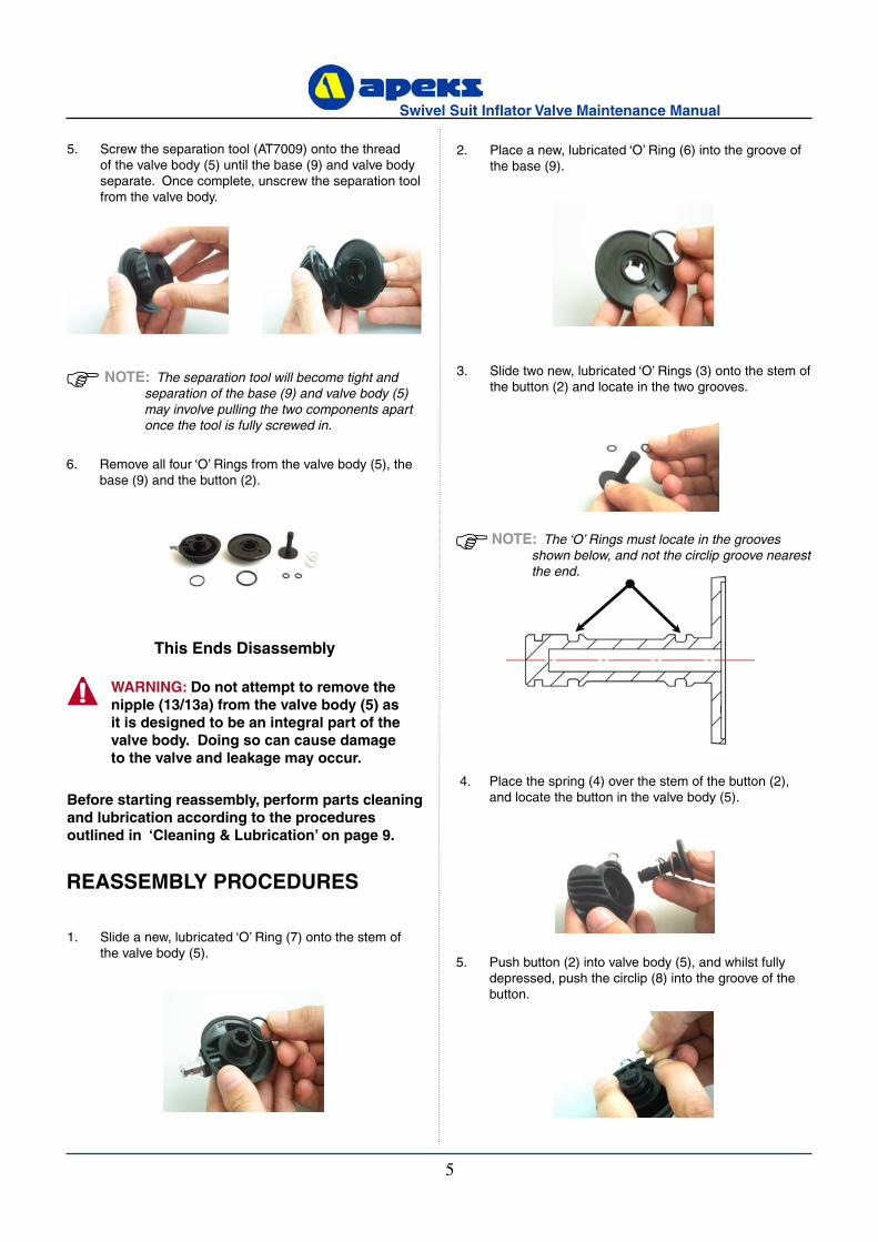
6. Remove all four ‘O’ Rings from the valve body (5), the base (9) and the button (2).
3. Slide two new, lubricated ‘O’ Rings (3) onto the stem of the button (2) and locate in the two grooves.
5. Screw the separation tool (AT7009) onto the thread of the valve body (5) until the base (9) and valve body separate. Once complete, unscrew the separation tool from the valve body.
5. Push button (2) into valve body (5), and whilst fully depressed, push the circlip (8) into the groove of the button.
Before starting reassembly, perform parts cleaning and lubrication according to the procedures outlined in ‘Cleaning & Lubrication’ on page 9.
WARNING: Do not attempt to remove the nipple (13/13a) from the valve body (5) as it is designed to be an integral part of the valve body. Doing so can cause damage to the valve and leakage may occur.
This Ends Disassembly
4. Place the spring (4) over the stem of the button (2), and locate the button in the valve body (5).
1. Slide a new, lubricated ‘O’ Ring (7) onto the stem of the valve body (5).
2. Place a new, lubricated ‘O’ Ring (6) into the groove of the base (9).
REASSEMBLY PROCEDURES
NOTE: The separation tool will become tight and separation of the base (9) and valve body (5) may involve pulling the two components apart once the tool is fully screwed in.
NOTE: The ‘O’ Rings must locate in the grooves shown below, and not the circlip groove nearest the end.

6
Swivel Suit Inflator Valve Maintenance Manual
7
Swivel Suit Inflator Valve Maintenance Manual
3. Fit the valve to the suit following the re-assembly procedure. Seal off the neck and cuffs then submerge the chest area of the suit, inspect the inside of the suit for any sign of water ingress.
Testing Procedures
9. Refit the valve to the suit using a torque wrench and a back nut tool (AT43). The valve should be torqued to 4lbs/ft or 5.4Nm.
8. If a new decal (1) is to be fitted, the button (2) must be degreased first.
2. Check that the valve body rotates approx 350°.
WARNING: Ensure all legs are correctly clipped into the groove, otherwise leakage may occur and/or the valve may seperate during use.
6. Push valve body (5) into base (9) ensuring that the ‘O’ Rings are still in place. All the legs on the base will click into the groove of the valve body when assembled correctly.
7. Rotate the valve body (5). It should rotate smoothly through an angle of approximately 350° without being over tight.
NOTE: Rotate the valve body (5) clockwise until it reaches it’ stop and, whilst holding the valve, rotate the back nut (11) to tighten. This aides assembly and also reduces the chance of damaging the backing patch or suit. An Apeks backing patch (AP0166) should be used to ensure no leaks can occur between the valve and the suit.
CAUTION: Protective eyewear must be worn at all times during testing.
1. This test should be carried out before the valve is fitted to the suit;
Attach the Swivel Suit Inflator Valve to a suitable MP
gas supply using a quick release hose (AP0157 if Apeks type, or AP0153 if Seatec type).
Pressurise slowly and submerse valve in water; there
should be no leakage of gas. If leakage occurs, refer to “Table 1 - Troubleshooting Guide” for corrective ac-tions.
Now, depress the button fully; gas should flow audibly through the valve. If there is no flow of gas, refer to “Table 1 - Troubleshooting Guide” for corrective actions.

6
Swivel Suit Inflator Valve Maintenance Manual
7
Swivel Suit Inflator Valve Maintenance Manual
Table 1 - Troubleshooting Guide
SYMPTOM POSSIBLE CAUSE TREATMENT
Valve leaks when button not de-pressed.
1. ’O’ Rings (3) damaged or worn. 1. Replace ‘O’ Rings.
2. Internal sealing surface damaged. 2. Replace valve body.
3. ‘O’ Ring grooves in button damaged. 3. Replace button.
4. Dirt /salt deposits present on internal sealing surface.
4. Disassemble valve and thor-oughly clean all parts before re-assembly.
Valve does not operate correctly
1. Dirt /salt deposits present within valve assembly.
1. Disassemble valve and thor-oughly clean all parts before re-assembly.
2. Spring damaged or not fitted. 2. Replace spring.
Water leakage into suit
1. ‘O’ Rings (6) and/or (7) damaged or worn. 1. Replace ‘O’ Rings.
2. The valve has not been tightened in the suit properly. 2. Re-tighten the valve.
3. An incompatible backing patch has been fitted to the suit.
3. Fit an Apeks backing patch AP0166.
4. There is no backing patch fitted. 4. Fit an Apeks backing patch AP0166.
5. Dirt/salt deposits present internally. 5. Clean the valve.
Restricted air flow
1. M.P of supply gas too low. 1. Ensure M.P is set at 9.5 ±0.5 bar.
2. Dirt /salt deposits present within valve assembly
2. Disassemble valve and thor-oughly clean all parts before re-assembly.
3. Restrictions from undersuit. 3. Ensure undersuit allows gas to vent out of the valve.
Table 2 - Recommended Tool List
PART NO. DESCRIPTION APPLICATION
AT43 Back Nut Tool Removal of back Nut.
AT7009 Separation Tool Separation of valve body and base.
AT54 ‘O’ Ring removal tool Removal of circlip and ‘O’ Rings
n/a Torque Wrench Removal and fitting of valve to suit.

8
Swivel Suit Inflator Valve Maintenance Manual
9
Swivel Suit Inflator Valve Maintenance Manual
Table 3 - Recommended Lubricants & Cleaners
LUBRICANT / CLEANER APPLICATION SOURCE
Christo-Lube® MCG-111(Lubricant)
All ‘O’ Ring seals Apeks Marine Equipment LtdPN AP1495, or
Lubrication Technologies310 Morton StreetJackson, OH 45640, USA(800) 477-8704
Biox(Cleaning agent)
Biological immersion fluid for reus-able stainless steel and brass parts.
Solent Divers Ltd122-128 Lake Rd, Portsmouth,Hants, PO1 4HH
White distilled vinegar (100 gr.)(Cleaning agent)
Acid bath for reusable stainless steel and brass parts.
“Household” grade
Liquid dishwashing detergent diluted with warm water(Cleaning agent)
Degreaser for brass and stainless steel parts; general cleaning solu-tion for plastic and rubber
“Household” grade
CAUTION: Silicone rubber requires no lubrication or preservative treatment. DO NOT apply grease or spray to silicone rubber parts (eg. Diaphragm, Exhaust Valves.) Doing so may cause a chemical breakdown and premature deterioration of the material.
CAUTION: Do not use muriatic acid for the cleaning of any parts. Even if strongly diluted, muriatic acid can harm chrome plating and may leave a residue that is harmful to ‘O’ Ring seals and other parts

8
Swivel Suit Inflator Valve Maintenance Manual
9
Swivel Suit Inflator Valve Maintenance Manual
Cleaning & Lubrication Procedure
General Cleaning of all Parts1. Place all components in an ultrasonic cleaning bath containing an appropriate cleaning solution, such as Biox.
2. The components should be cleaned for 6 minutes, depending upon their condition. Longer cleaning times may used if required.
3. Rinse the components in warm fresh water.
4. The components should then be blown dry or left to dry naturally.
Lubrication and DressingAll ‘O’ Rings should be lubricated with Christo-Lube® MCG-111. Dress the ‘O’ Rings with a very light film of grease, and remove any visible excess by running the ‘O’ Ring between thumb and forefinger. Avoid applying excessive amounts of Christo-Lube grease, as this will attract particulate matter that may cause damage to the ‘O’ Ring.
NitroxWhen it comes to issues of nitrox safety and compatibility, the concerns lie primarily with the first stage as it is subjected to high inlet pressures. High inlet pressures lead to adiabatic compression or heating of the gas. As they leave the factory, standard Apeks regulators are suitable for use with oxygen enriched gases (i.e. nitrox, etc.) providing the oxygen content does NOT EXCEED 40% (EAN40).Any Apeks regulator, when properly cleaned, lubricated and assembled, is authorised for use with enriched air nitrox (EAN) up to 100% (EAN100). It is authorised because it has undergone adiabatic compression testing and the authorised service kit com-ponents and lubricants are compatible in elevated oxygen environments. During cleaning, a mild detergent is used to remove condensed hydrocarbons (compressor oils) from the inside passageways of the first stage. For the first stage to remain EAN100 compatible, only use hyperfiltered compressed gas (hydrocarbons < 0.1 mg/m3). Ordinary compressed breathing air to BS EN 12021:1999 does not meet this criteria. Once ordinary breathing air is used, the first stage is no longer EAN100 compatible until it is cleaned and serviced again.Although regulator second stage components are not exposed to high pressure EAN, Apeks recommends that the same cleaning procedures be followed for the complete regulator. This prevents the possibility of cross contamination and guarantees the cleanliness of the entire regulator.
WARNING: Please check the regulations regarding Nitrox in your particular country as this may differ from Apeks standard policy.

10
Swivel Suit Inflator Valve Maintenance Manual
11
Swivel Suit Inflator Valve Maintenance Manual
Table 5 - Test Bench Specifications
TEST ACCEPTABLE RANGE
Leak Test No Leaks permitted
Table 4 - Torque Specifications
PART NUMBER DESCRIPTION / KEY NUMBER TORQUE
AP1572,AP1573 Extended Back Plate, Back Nut. 4lbs/ft (5.4Nm)

10
Swivel Suit Inflator Valve Maintenance Manual
11
Swivel Suit Inflator Valve Maintenance Manual
1 AP5015 Decal 9 AP7006 Base
2 AP7008 Button 10 AP1573 Back Nut
3 AP1154* ‘O’ Ring (2x) 11 AP1572 Extended Back Plate
4 AP7002 Spring 12 AP1409 ‘O’ Ring
5 AP7007 Valve Body 13 AP7004 Nipple
6 AP1277* ‘O’ Ring 13a AP7005 SeaTec Nipple
7 AP1298* ‘O’ Ring
8 AP7010 Circlip
Swivel Suit Inflator Valve Exploded Parts Diagram
* All marked items must be replaced when serviced. Service Kit Part No. AP0224/S

12
Swivel Suit Inflator Valve Maintenance Manual
Notes

12
Swivel Suit Infl ator Valve Maintenance Manual
LOW PROFILE SUIT INFLATOR VALVE
AUTHORISED TECHNICIANS
Apeks Marine Equpment LtdNeptune Way, Blackburn, Lancs, England, BB1 2BT
MAINTENANCE MANUAL
FOR
TECHNICAL SUPPORT