switching systemscytec-ate.com/downloads/cytec_catalog.pdf · cxr/2(4x1) -ll-bnc or -triax ......
TRANSCRIPT

2555 Baird Road, Penfield, New York 14526
FOR TECHNICAL ASSISTANCE CONTACT 1-800-346-3117www.cytec-ate.com or [email protected]
SWITCHING SYSTEMS
FORAUTOMATIC TEST, DATA ACQUISITION,
COMMUNICATIONS AND CONTROLS
COMMUNICATIONSAUTOMATED TEST ANDDATA ACQUISITION
COMPUTERCONTROLLED
GPIB, IEEE488,RS232, RS422,
ETHERNET, LAN,UNIVERSAL SERIAL BUS,
PARALLEL TTL
MULTIPLEXERS
MATRIX
MICROWAVE AND RF
NETWORK AND INTERNET
VIDEO
FIBER OPTICSDISCRETE RELAYS
HIGH VOLTAGE OR CURRENT
VXI, VME, COMPACT PCIBUS SWITCH MODULES
PLUG-IN PCMODULES

CYTEC Corp., supplier of the most comprehensive range of Programmable Switch-ing Systems, continues to expand its product line by offering the following NewProducts for automated test, data acquisition or communications:
CONTACT 1-800-346-3117, [email protected] OR WWW.CYTEC-ATE.COMFOR TECHNICAL ASSISTANCE AND A COMPLETE CATALOG WITH PRICING!
October 2005
2555 Baird Road, Penfield, New York 14526 (585) 381-4740 FAX (585) 381-0475
NEW PRODUCT NEWSNEW PRODUCT NEWSNEW PRODUCT NEWSNEW PRODUCT NEWSNEW PRODUCT NEWS
MOST Bus / Toslink Fiber Optic FX/1x8-TL Switch ModulesThis opto-electrical-opto module switches Transmit and Receive pairs in an 8x1 or 1x8 con-figuration. Module can be configured for a variety of applications such as audio, MOST bus, orserial data communications. Modules can be used in FO Series 16, 32 or 128 channel driverchassis. Call or e-mail for application assistance, pricing and availability.
Low Leakage ModuleCXR/2(4x1)-LL-BNC or -Triax for low current or high resistance measurements
Dual 4x1 low leakage modules can be used to measure currents downto femtoamps (10E-15 amps), or resistances up to teraohms (10E+12).Modules have jumpering options to allow outer conductor isolated or useas a driven guard. BNC or Triax connectors. Fits in Cytec CXAR Series16, 32, or 128 channel driver chassis. Module can be wired to form 1x8or 4x2 configurations. Bus bars available to form larger matrices. Callor e-mail for details about your specific needs.
Microwave systems now go up to 40 GHzCytec can now build our CXM Series of microwave switching systems using re-lays with a frequency range of DC to 40 GHz.Call for Price and availability. Custom Microwave and RF systems built to yourrequirements.
Low Cost Blocking, Nx4 DC to 1 GHz RF or Video MatrixNew CXL/8x4 Switch Module allows for low cost configuration of 8x4, 16x4 or 32x4 matrices with bandpass of 1 GHz in 8x4 (-3dB) and upto 650 MHz (-3 dB) for 50 ohm 32x4 systems. Blocking architecture means that you can connect any input to any output but previouslyconnected paths may need to be interrupted momentarily while the switch is reconfigured. If you can tolerate this interruption that onlyoccurs during configuration this switch can save you as much as 50% off the price of non-blocking systems with similar specs and take uphalf the rack space. Call 1-800-346-3117 for configuration specific pricing.
Price Lowered on Solid State Analog and Digital Matrices!!!Cytec has lowered the prices on our large solid state digital and analog matrices by as much as50%. Prices have been lowered on:TX Series of modular analog matrices -- DC to 140 MHz (small signal 50 and 75 ohm) up to256x256 configuration.DX/64x64 high speed differential signal matrices -- RS422, ECL, PECL, LVDS, and CML up to1.3 Gbps.DX/256x256 TTL and RS422 matrices -- signals up to 40 Mbps. Check the web for our latestprices! Fill out a catalog request form to receive the price list in PDF.www.cytec-ate.com
�� �� �� �� ��� ��� �� � �� ��

CONTCONTCONTCONTCONTAAAAACT 1-800-346-3117, SALES@CYTECCT 1-800-346-3117, SALES@CYTECCT 1-800-346-3117, SALES@CYTECCT 1-800-346-3117, SALES@CYTECCT 1-800-346-3117, [email protected] OR WWW.COM OR WWW.COM OR WWW.COM OR WWW.COM OR WWW.CYTEC.CYTEC.CYTEC.CYTEC.CYTEC-----AAAAATETETETETE.COM.COM.COM.COM.COMFOR TECHNICAL ASSISTFOR TECHNICAL ASSISTFOR TECHNICAL ASSISTFOR TECHNICAL ASSISTFOR TECHNICAL ASSISTANCE AND A COMPLETE CAANCE AND A COMPLETE CAANCE AND A COMPLETE CAANCE AND A COMPLETE CAANCE AND A COMPLETE CATTTTTALALALALALOG WITH PRICING!OG WITH PRICING!OG WITH PRICING!OG WITH PRICING!OG WITH PRICING!
WWWWWARRANTYARRANTYARRANTYARRANTYARRANTYCYTEC Corp. warrants that all products are free from defects in Material or Workmanship for a period of 5 years and that all
switches are guaranteed for their rated operations.
HXC Series High Current Switching Systems handle up to 150 Amps!
Cytec is proud to introduce a complete line of High CurrentSystems. These systems are capable of switching or break-ing up to 150 amps AC or DC and may be wired into almostany desired configuration. Relays available for 40 amps, 60amps or 150 amp applications. Chassis available to drivefrom 16 to 128 relays. Call or e-mail for configuration assis-tance, pricing and availability.
Network Test Access Switches and Power Over Ethernet Test SwitchesRJV and RJG Series of Ethernet Test Access Switches
Failsafe and redundancy switches
Specs:Max Switched Current 40 A 60 A 150 AMax Switched Voltage 277 VAC, 30 VDC 277 VAC, 400 VDC 277 VAC, 400 VDCShort term carry current 60 amps, 10 mins. 120 Amps, 15 mins. 300 Amps, 10 mins.Breakdown voltage 2000 Volts peak 2500 Volts peak 2,500 Volts peakMechanical life (operations) 10,000,000 200,000 100,000Electrical life at max load 100,000 3,000 3,000Switch time 20 ms 50 ms 50 ms
The RJG Series of Ethernet Switches is designed to handle copper1000BaseT Gigabit Ethernet signals. They switch all 8 wires of Cat5 orCat6 wiring in 1x12 increments for multiplexers or 6x3 matrix incre-ments.
Allows test access to network segments from your desktop, your home,or across the planet and reduces the number of analyzers needed.Both systems use mechanical relays allowing Power Over Ethernet tobe switched.
The RJV Series is cost effective for 10 and 100BaseT systems switch-ing 2 pairs on CAT5 RJ45 connectors. Modules available as four 1x2'sin latching or non-latching, 12x1 multiplexers or 6x4 matrices. Up to 12modules per chassis. Many configurations possible.
�������������� ��� �������� ������
��������������� ���� �������� ������
�������������
�� ��������������� ! ���������������������
Cytec's Failsafe Switch Systems may be used to provide Network Protection, redundant system switch over for Data Communications orPower, and even a means to switch to your equipment's backup system when needed. Our passive systems act like a piece of cable sothey can replace messy patch panels, and they permit reconfiguration of systems without ever leaving your desk.
Systems Available for:Copper Ethernet -- Coax, 10 Base-T, 100 Base-TX, 1000 Base-T.Fiber -- Multimode or Singlemode.WAN and Telco -- POTS to T3 copper, OC1 to OC12 Fiber, DSL.Coaxial and Cable -- DC to 40 GHz, Microwave or Cell.Serial Data -- RS232, 422, 485, 530, ECL, LVDS, USB, Infiniband.Video -- Virtually any and all types.Power -- DC or AC, up to 5000 Volts and 150 amps.
New JX Series High Current Switch Module handles up to 30 Amps!The new JX8/KP-A and JX8/KP-C Switch Modules handle up to 30 amps of AC at 280 Volts or 20 amps of DC at 28 Volts. Rated to100,000 operations at full load. This module fits into any existing JX system but does require two open slots per module.Call or e-mail for price and availability.

CYTEC Corp., supplier of the most comprehensive range of Switching Systems,continues to expand its product line by offering the following New Products:
CONTACT 1-800-346-3117, [email protected] OR WWW.CYTEC-ATE.COMFOR TECHNICAL ASSISTANCE AND A COMPLETE CATALOG WITH PRICING!
NEW 4800 SERIES 64X64 DIGITAL SIGNAL SWITCH MATRIX
• Computer control via GPIB, RS232, or 10BaseT Ethernet.• Optional Manual control.• LED front panel indication of latched switch points.• Bidirectional, all wave lengths and baude rates switched.• Systems from 1 to 1000 switch points.• Remote Status Feedback of switch position.
• Single mode or multimode.• Many connector options including FC, SC, and ST.• Insertion Loss as low as .3 dB.• Discrete switches, group switches or failsafe switches• Custom systems available.• Software support for most programming platforms.• Five year warranty.
Mainframe systems available as 16 through 128 switch points in 3.5" tall to 10.5" tall chassis. Larger systems canbe assembled using a Mesa Controller and multiple expansion chassis. Call CYTEC with your configuration.
The 4800 series Digital 64X64 Matrix switches singleended or differential signals up to 2.0 GBPS. Avail-able for ECL, PECL, LVPECL, LVDS, CML, HDTV ormany other digital signal types. Input and outputtransition boards furnish level translations or sig-nal type conversion and connector options.
• Available in incremental sizes from 16x16 to 64x64.
• Matched path lengths for low skew.
• Rise and Fall times as fast as 150 ps (20% to 80%).
• Completely non blocking (any input to any output).
• Full fan-out (any input to several or all outputs).
• Available as dual differential Clock and Data Matrices.
• Jitter correction feature actually improves poor signals.
• Multiple connector options.
• Computer control via GPIB, RS232, or 10BaseT Ethernet.
• Front panel manual control with LCD display.
• Remote Status Feedback of switch position.
• Full five year warranty.
FO/16 Mainframe front panel with MC/16 Pushbutton manual control
SYSTEM FEATURES:
SYSTEM FEATURES:
4800/64x64 Differential ECL/PECL Matrix
Prices starting at $20,000.00Availability: 60 days ARO.
This system incorporates an advanced solid state switchfabric that can actually help restore signal levels, correctdeterministic jitter and clean up rise time problems asso-ciated with wiring and cable runs. Transition boards arealso available separately for performing signal conver-sions in applications which do not require switching. CallCYTEC's Technical Sales Department to discuss your ap-plication.
JULY 2002
2555 Baird Road, Penfield, New York 14526 (585) 381-4740 FAX (585) 381-0475
NEW PRODUCT NEWS
NEW FIBER OPTIC SYSTEMSFO SERIES OF PASSIVE FIBER SWITCHING SYSTEMSCYTEC's New FO Series of Fiber Optic Switches useelectro mechanical optical relays to form 1xN multi-plexers or NxM matrices. These 19" rack mount orbench top systems are available in a variety of con-figurations.
Pricing starts as low as $1,500.00Availability: 30 to 45 days ARO.

CONTACT 1-800-346-3117, [email protected] OR WWW.CYTEC-ATE.COMFOR TECHNICAL ASSISTANCE AND A COMPLETE CATALOG WITH PRICING!
NEW JX32/L2 SWITCH MODULEThis module has 32 two pole relays as shown in thefigure below with signal inputs wired to two 34 pinheader connectors. The two 16x1 muxes can bejumpered together to form one 32x1 mux. The outputsare available on a 10 pin header connector or can bejumpered to the card edge connector which plugs intothe backplane. It is available with Type A relays only.The relay specs are listed at the bottom of this page.
This module fits into all standard JX mainframes orExpansion chassis. By using 16 of these modules, asingle JX mainframe can be configured as a 512x1 twopole multiplexer or a 1016x1 single pole multiplexer.
HEADER CONNECTOR Pins 0-15 Top
HEADERCONNECTOR
BA
CK
PL
AN
E
HEADER CONNECTOR Pins 16-31 Btm
NEW CPCI/64x1 TWO POLE MATRIX
NEW VME/16X16 RF MATRIXCYTEC's VME/16x16 Video and RF Matrix moduleuses a solid state switch fabric and is a nonblocking,full fan-out 16x16 matrix with bandpass to 180 MHz.This 6U VME or B sized VXI module may be used for50 or 75 ohm signals and comes with SMB connec-tors.
Typical applications include:50 ohm RF communication signals.75 ohm Video.75 ohm DS3.
SPECIFICATIONS:
Price: $420.00Availability: 1 week ARO
01
15210
2
15
16 InputBuffers
16outputBuffers
Bandpass:75 ohms, 0.2 Vpp: >180 MHz, -3 dB75 ohms, 2.0 Vpp: >100 MHz, -3 dB50 ohms, 0.2 Vpp: >225 MHz, -3 dB50 ohms, 4.0 Vpp: >165 MHz, -3 dB50 ohm peak gain: +6 dB @ 150 MHzFlatness: 1 dB to 40 MHzCrosstalk: All hostile = <-55dB @ 10MHzIsolation: Input to Output = <-60dB @ 10MHz
TYPE A RELAY SPECIFICATIONS :Contact Rating: 30 Watts, 62.5 VAMax. Switching Voltage: 110 VDC, 125 VACSwitching Current: 1.0 ACarrying Current: 2.0 ABreakdown Voltage: 750 VOperate Time: 3 ms
8x1
8x1
160 Pin High Density Connector
Jumpers
8x1
8x1 8x1
8x1
8x1
This Compact PCI / PXI switch module has 8 indepen-dent 2 pole, 8x1 multiplexers. Each 8x1 segment maybe jumpered to another or used individually to providea large variety of configurations. All signals are broughtout to a high density 160 pin connector. The moduleuses Type A relays only. The relay specs are listed onthe bottom of this page.
Price: $750.00Availability: 2 weeks ARO
GENERAL SPECIFICATIONS:
Price: $3,500.00 each.Available 2 weeks ARO.
Software support includes programming examples in C and driv-ers for National Instruments LabView or LabWindows program-ming platforms. Demonstration modules are available on request
VXI Revision: 1.4.Module Size: VME 6U or VXI B size.Logical Address: per DIP Switch setting.Communication: Register Based.Bus/Address Type: D16/A16/D08(O).Write Cycle: less than 500 nsec.Read Cycle: less than 500 nsec.
WARRANTYCYTEC Corp. warrants that all products are free from defectsin Material or Workmanship for a period of 5 years and that allswitches are guaranteed for their rated operations.

CYTEC Corp., Manufacturer of the most comprehensive range of SwitchingSystems, continues to expand its product line and is now offering the followingNew Products:
CONTACT 1-800-346-3117 [email protected] OR WWW.CYTEC-ATE.COMFOR TECHNICAL ASSISTANCE AND A COMPLETE CATALOG WITH PRICING!
JULY 2003
2555 Baird Road, Penfield, New York 14526 (585) 381-4740 FAX (585) 381-0475
NEW PRODUCT NEWS
NEW TX SERIES 128X128 COAXIAL 50 or 75 OHM SWITCH MATRIXThe TX/128x128 Series furnishes both nonblocking and full fan-out solid state switching of 50 or 75 ohmcoaxial signals up to 140 MHz. Suitable for RF, Radar, Video, DS3 or other single ended coaxial signals.This system will also soon be available as a 256x256 blocking configuration.
• Modular System available in sizes from 16x16 to 128x128.
• Small signal bandpass of 140 MHz (0.2 Vpp).
• Large signal bandpass of 50 MHz (8 Vpp).
• Completely nonblocking (any input to any output).
• Full fan-out (any input to several or all outputs).
• Amplifier modules available for buffering or level conversion.
• Isolation of -60 dB at 40 MHz for non adjacent inputs.
• Isolation of -48 dB at 10 MHz for all hostile.
• Patch panels allows for multiple connector options.
• Computer control via GPIB, RS232, or Ethernet.
• Optional front panel Manual Control with LCD display.
• Remote Status feedback of switched positions.
• Full five year warranty.
SYSTEM FEATURES:
TX Series SolidState CoaxialMatrix
Telephone for Pricing. Availability: 60 days ARO
CYTEC's TX/128x128 Coaxial Matrix is a modular system with upto 128 inputs and 128 outputs in a nonblocking, full fan-out con-figuration. The system accepts up to eight input modules andeight output modules with 16 connections per module. Eachmodule can be configured with or without amplifiers for 50 or 75ohm signals up to +/- 4 volts. System may be purchased origi-nally as a 16x16 and expanded at any time by simply adding moremodules.
CXR/8x1-LL LOW LEAKAGE MODULE
MODULE FEATURES:Faraday Shielded Signals eliminate relay drive leakage.Shielded Low Leakage Relays minimizes relay drive coupling.Output Isolation Relays minimize leakage "addition".Dual Commons allow multiple modules to be interconnected.Available Connectors include BNCs, Twin Ax and Triax.Jumper positions provide for Grounded Guard, Isolated Guardor Driven Guards.Suited to very high IR, low current to femtoamps and highspeed capacitance measurements.
TX/128x128 Matrix Rear Panel
This new switch module fits into the CXAR Series Chassis and provides signal isolations on the order of 10^15 Ohms.Applications include high insulation resistance measurements, low current switching down to femtoamps and highspeed capacitance measurements.
shie
ld
shie
ld
shie
ld
shie
ld
shie
ld
shie
ld
shie
ld
shie
ld
jumpers0 jumpers
1jumpers
2jumpers
3jumpers
4jumpers
5jumpers
6jumpers
7
ISO 0
C 0
shie
ld
jumpers
C 1
shie
ld
jumpers
ISO 1••••••
•Pricing: $450.00 with Triax Connectors $380.00 with BNCs.Availability: 30 days ARO

CONTACT 1-800-346-3117, [email protected] OR WWW.CYTEC-ATE.COMFOR TECHNICAL ASSISTANCE AND A COMPLETE CATALOG WITH PRICING!
WARRANTYCYTEC Corp. warrants that all products are free from defectsin Material or Workmanship for a period of 5 years and that allswitches are guaranteed for their rated operations.
DX SERIES 64x64 HIGH SPEED DIGITAL SIGNAL SWITCH MATRIXThe DX Series Digital 64x64 Matrix switches single-ended or differential signals up to 2.0 Gbps. Avail-able for ECL, PECL, LVPECL, LVDS, CML, HDTV ormany other digital signal types. Input and outputtransition boards supply level translations, signalconversion or alternate connector options.
• Available in incremental matrix sizes from 16x16 to 64x64.
• Matched path lengths for low skew.
• Rise and Fall times as fast as 150 psec (20% to 80%).
• Completely nonblocking (any input to any output).
• Full fan-out (any input to several or all outputs).
• Available as dual differential Clock and Data Matrices.
• Jitter correction feature actually improves poor signals.
• Multiple connector options.
• Computer control via GPIB, RS232 or Ethernet.
• Optional front panel Manual Control with LCD display.
• Remote Status Feedback of all switch positions.
• Full five year warranty.
SYSTEM FEATURES:
DX Series 64x64 Differential ECL/PECL Matrix Rear
Prices starting at $20,000.00Availability: 60 days ARO.
This system incorporates an advanced solid state switchfabric that helps restore signal levels, corrects determin-istic jitter and cleans up rise time problems associatedwith wiring and cable runs. Input and Output TransitionModules are also separately available that perform sig-nal conversions in applications which do not requireswitching. Call CYTEC's Sales Department to discussyour application.
NEW SOLID STATE DX SERIES 256x256 DIGITAL SWITCH MATRIX
The Solid State DX/256x256 Solid State Series is avery high density, low cost switch matrix that isdesigned to switch digital TTL or CMOS signalsup to 40 Mbps ( 80 Mbps NRZ ). Input and OutputTransition Modules can be provided for differen-tial signals or level conversion allowing for signaltypes such as RS232, RS422 or almost any digitaldata stream. Optional Patch or Breakout Panelsfurnish almost any connector type specified by theend user. The Matrix may be configured formultiwire switching, such as a Dual Clock and DataMatrix or Rx and Tx signals.DX/256x256 Solid State Switch Matrix
Prices starting at $20,000.00Availability: 60 days ARO.SYSTEM FEATURES:
• Available in incremental sizes from 64x64 to 256x256.
• Completely nonblocking (any input to any output).
• Full fan-out (any input to several or all outputs).
• Available as dual differential Clock and Data Matrices.
• Multiple connector options.
• Computer control via GPIB, RS232, or Ethernet.
• Optional front panel Manual Control with LCD display.
• Remote Status Feedback of all switch positions.
• Full five year warranty.
SOFTWAREFree Example/Driver programs are available for most modernOperating systems. Platforms include: C, Visual Basic, Java,LabView and LabWindows.
• Applications include TTL, CMOS, RS232 and RS422 data.
BULLETINMESA-6
2555 Baird Road, Penfield, New York 14526 (585) 381-4740 FAX (585) 381-0475
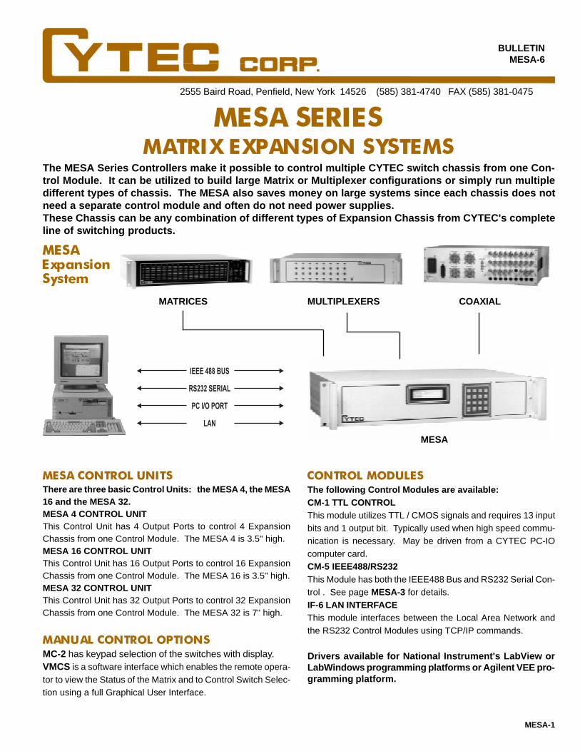
MESA SERIESMATRIX EXPANSION SYSTEMS
The following Control Modules are available:CM-1 TTL CONTROLThis module utilizes TTL / CMOS signals and requires 13 inputbits and 1 output bit. Typically used when high speed commu-nication is necessary. May be driven from a CYTEC PC-IOcomputer card.CM-5 IEEE488/RS232This Module has both the IEEE488 Bus and RS232 Serial Con-trol . See page MESA-3 for details.IF-6 LAN INTERFACEThis module interfaces between the Local Area Network andthe RS232 Control Modules using TCP/IP commands.
CONTROL MODULESMESA CONTROL UNITS
COAXIAL MATRICES
MESAExpansionSystem
The MESA Series Controllers make it possible to control multiple CYTEC switch chassis from one Con-trol Module. It can be utilized to build large Matrix or Multiplexer configurations or simply run multipledifferent types of chassis. The MESA also saves money on large systems since each chassis does notneed a separate control module and often do not need power supplies.These Chassis can be any combination of different types of Expansion Chassis from CYTEC's completeline of switching products.
MULTIPLEXERS
IEEE 488 BUS
RS232 SERIAL
PC I/O PORT
LAN
MESA-1
MESA
MANUAL CONTROL OPTIONSMC-2 has keypad selection of the switches with display.VMCS is a software interface which enables the remote opera-tor to view the Status of the Matrix and to Control Switch Selec-tion using a full Graphical User Interface.
There are three basic Control Units: the MESA 4, the MESA16 and the MESA 32.MESA 4 CONTROL UNITThis Control Unit has 4 Output Ports to control 4 ExpansionChassis from one Control Module. The MESA 4 is 3.5" high.MESA 16 CONTROL UNITThis Control Unit has 16 Output Ports to control 16 ExpansionChassis from one Control Module. The MESA 16 is 3.5" high.MESA 32 CONTROL UNITThis Control Unit has 32 Output Ports to control 32 ExpansionChassis from one Control Module. The MESA 32 is 7" high.
Drivers available for National Instrument's LabView orLabWindows programming platforms or Agilent VEE pro-gramming platform.

MESA CONTROL UNITSThere are three basic models of the MESA Control Unit: the MESA 4, the MESA 16 and the MESA 32. Theycontain Power Supplies and an Expansion Motherboard. The Control Module and Expansion Interface Mod-ules plug into the Motherboard so that one Control Module can control up to 32 Expansion Chassis.The System shown in Fig. 1 has a MESA 16 Control Unit and four Expansion Chassis arranged and addressedas a 32x16 Matrix. This leaves 12 additional ports to expand the system by adding twelve Expansion Chassis.
MESA 4 CONTROL UNIT
MESA 16 CONTROL UNIT
This is a 19" rack mountable chassis, 3.5" high and 12" deepwhich will accept any of the Control Interfaces and 4 ExpansionPorts to control 4 Expansion Chassis. The Power Supply hassufficient logic power to drive all 4 Expansion Chassis and re-lay power to energize up to 200 relays at one time.
This is a 19" rack mountable chassis, 3.5" high and 12" deepwhich will accept any of the Control Interfaces and 16 Expan-sion Ports to control up to 16 Expansion Chassis as shown inFig. 1 . The Power Supply has sufficient logic power to drive all16 Expansion Chassis and relay power to energize up to 200relays at one time.
MESA 32 CONTROL UNIT
This is a 19" rack mountable chassis, 7" high and 15" deepwhich will accept any of the Control Interfaces and 32 Expan-sion Ports to control up to 32 Expansion Chassis. The PowerSupply has sufficient logic power to drive all 32 Expansion Chas-sis and relay power to energize up to 200 relays at one time.
RELAY POWER REQUIREMENTSThe 12 volt relay power supplied with the MESA Control Units is sufficient for most Matrix or Multiplex operations.However, some applications require a larger number of switches to be closed. For these cases, two options are offered:Auxiliary Power Supply or Powered Expansion Chassis.
POWERED EXPANSION CHASSIS
This is a separate 19" rack mounting chassis, 3.5" high and 12"deep with +5 volt logic power for up to 32 Expansion Chassisand relay power to energize up to 500 relays.
MESA-2
AUX-1 POWER SUPPLY
Where the power requirement in individual Expansion Chassisis very high, each Expansion Chassis can be supplied with itsown relay power supply capable of energizing up to 200 relaysper Expansion Chassis.
CONTROL MODULES
The Control Modules are plug compatible with all the MESA control Units and have the same commandstructures for Control and Switch Selections.The commands for Mode Control are Latch, Unlatch, Matrix Mode, Mux Mode, Clear or Status Request.The standard commands for selecting a Switchpoint are to select Matrix, Module and Switch.
These modules are available to control the MESA Units from TTL, IEEE488 BUS, RS232 Serial Port or 10Base-T Ethernet LAN.They include standard or special firmware for different configurations such as:In a Matrix configuration, the command can be Input # and Output # selection for the crosspoint.In a Multiplexer application, the command can be Channel # selection for one switch selection only.
LX/128-E #0 LX/128-E #1
LX/128-E #3 LX/128-E #2
0 thru 15 16 thru 31
0thru
7
8thru
15
0123456789101112131415Expansion Ports
Mesa 16 Control Chassis
Remote Control
AC Input DCPowerSupply
ManualControl
Expansion Interface Cable
Expansion Interface Cable
Fig. 1
MESA TO EXPANSION CHASSIS DISTANCEIndividual Expansion Chassis are normally supplied with 6 foot cables. The expansion chassis can be provided with ribboncables up to a length of 20 feet on request. Expansion chassis may be located up to 200 feet from the MESA if a better typeof cable is used. To discuss these options please contact CYTEC's sales staff.

CM-5 IEEE488/RS232This Module combines both the IEEE488 Talk Listen Con-trol and the RS232 Serial Controls.
The Talk and Listen addresses are the same and are set bya 5 position DIP Switch. In the Listen Mode, the Matrix re-sponds to specific commands. The Talk Mode is used toreturn the Status of the Matrix.
IEEE488 TALK/LISTEN (GPIB)
RAM OPTIONThis option is available in the CM-5 and CM-6. Switch selec-tions are stored in the battery backup RAM (Random AccessMemory) with the following benefits:At Power-On, the switches can be latched to a preset defaultswitch configuration.In cases of momentary power loss, the matrix will be reset tothe last selected configuration before loss of power.Multiple configurations can be stored and recalled as requiredup to a maximum of 1,000 switch selections.
MESA-3
VMCS VIRTUAL MANUAL CONTROL SOFTWARE
Command SummaryM - Matrix - Select a specified Matrix.L - Latch - a specified Module and Switch in a Matrix.U - Unlatch - a specified Module and Switch in a Matrix.X - Multiplex - Latches a specified Switch and Clears allothers.C - Clear - Unlatches every switch in the Matrix.S - Status - The Status of the Matrix is returned to theController.F - Front Panel - Allows the disabling of front panel con-trols.P - Program - Allows the operator to set up Matrix vari-ables such as size and configuration and stores them innonvolatile memory.Typical Commands Are:Command FunctionL, n1, n2, n3 Latch Selected SwitchU, n1, n2, n3 Unlatched Selected SwitchX, n1, n2, n3 Mux Selected Switch
n1=Matrix, n2=Module, n3=SwitchC Clear entire systemC, n1 Clear matrix - n1=MatrixS Status of Entire SystemS, n1 Status of Matrix - n1=MatrixS, n1, n2, n3 Return Switch Status
n1=Matrix, n2=Module, n3=SwitchF, n1, n2, Front Panel Lock out
n1=0 disable, n1=1 enable, n2=accessP, n1, n2, n3 Program setup
n1=Parameter, n2=value, n3=access
MANUAL CONTROL OPTIONS
MC-2 KEYBOARD CONTROL
This Manual Control has a keyboard and LCD backlit displaymounted on the front panel.The LCD display has two lines of 16 alphanumeric characters.The top line displays the matrix commands and switch selec-tion.The bottom line displays the Status of a selected switch andError messages.This module can only be used with the CM-5 and CM-6 Con-trols.
This enables the remote operator to view the Status of the Ma-trix using a full Graphical User Interface.The matrix configuration is displayed and crosspoints are se-lected by a point and click operation. Each selected crosspointis prominently shown on the display.Custom labeling of the Inputs and Outputs can be programmed.One optional mode of operation prevents selection of switchesthat would interconnect two Inputs or two Outputs.
SOFTWARE
Drivers and/or sample programs are available with themost commonly available application programming lan-guages.
RS232 SERIALThe module can be configured as either a Data TerminalEquipment (DTE) or Data Communications Equipment(DCE). The Baud Rate is software programmable from 110to 19,200 Baud and is stored in nonvolatile memory.The Command structure is the same as the IEEE488 Mod-ule and has the following additional command features:E - Echo - Echoes all received characters back to the source.V - Verbose - Enables the matrix to return text strings in re-sponse to Commands, including error statements.H - Help - This is a summary of all the Commands.
RS232 Specific CommandsCommand FunctionB, n1, n2 Baud Rate - n1=rate, n2=accessE, n1, n2 Echo - n1=0 off, n1=1 on, n2=accessV, n1, n2 Verbose - n1=0 off, n1=1 on, n2=access
CM-6 LAN INTERFACEThis is a 10Base-T Ethernet LAN to RS232 interface modulewhich accepts data in TCP/IP format from the Local Area Net-work and outputs it in RS232 format to the MESA.When used with the RS232 Serial Module, it can control theMESA Control Units with the same Command Structure de-tailed in the CM-5.This interface can be used to access the MESA Control Unitfrom remote locations and from several users via the Local AreaNetwork using raw TCP/IP, or Telnet. Setup of the interface isthrough an external RS232 connection which allows you tospecify TCP/IP address, host name, gateways and many othernetwork parameters.
The LAN interface manual is available via e-mail in PDF formatby contacting CYTEC's sales staff.
Two types of Manual Control are offered: the MC-2 and theVMCS.

MESA-4
EXPANSION CHASSISThe versatility of the MESA Expansion System is that it enables up to 32 Expansion Chassis of different typesto be controlled from one Control Unit. This means that it is possible to build a complete Switching Systemrequiring Matrices, Multiplexers, Group Switches or Individual Relays by selecting the Expansion Chassisand Switch Modules most suitable for the application.
Each Expansion Chassis can be used for handling different types of signals including: Low Level Instrumen-tation, High Frequency Coaxial, Audio, Video, High Voltage or High Current. The Expansion Chassis can beremote from the Control Unit so that each chassis can be placed close to the signal source, reducing wiringlength with improvement in signal transmission.
The Expansion Chassis summarized below can be used in any combination with the MESA Control Unit. Fulldetails on each type of Chassis are described in respective bulletins which are part of the CYTEC catalog.The photograph shows a typical Switching System used to analyze ultrasonic data from a large number oftransducers and to record the data on several tape recorders.
RS SERIESMultiplexers (1xN configurations) for multi wire communicationssuch as RS232 and RS422. 9, 15 or 25 wires on D type connec-tors.RSM SERIESMatrix configurations for 9, 15, or 25 wire data signals.RJV SERIES4 and 8 wire signals on RJ45 connectors such as 10/100/1000BaseT.RJM SERIES2, 4, 6 or 8 wire signals on RJ45 connectors in matrix configura-tions.GX SERIESUsed specifically to switch large numbers of signals as a group.VX SERIESGeneral purpose, 256 channel units with a versatile range of mod-ules.JX SERIESHigh density 1xN or 2xN configurations. Up to a 1000x1 mux in asingle chassis.FX SERIESFiber Optic optical-electrical-optical (OEO) matrices available innon-blocking, full fan out matrix configurations up to 64x64.FO SERIESPassive Fiber Optic switches in a variety of configurations.PX SERIESCompact, cost effective matrices. 512 relays in a 3.5" highchassis.HDX 4600 SERIESHigh density matrices. Up to a 64x32 two wire matrix in a singlechassis.DX SERIESDigital matrices up to 64x64 for LVDS, PECL, ECL, HDTV or otherextremely fast digital signals.
Expansion chassis available in the follow-ing product series:
CXAR SERIES MULTIPLEXERSCoaxial 50 or 75 ohm 1xN multiplexers with bandpass up to 1GHz.CX SERIES MATRICESCoaxial 50 or 75 ohm NxM matrices with bandpass up to 700 MHz.CXM SERIESMicrowave multiplexers and matrices with bandpass up to 18GHz.VDX SERIES50 or 75 Ohm solid state, video or RF matrices up to 180 MHz.16x16 through 128x128 sizes.LXA SERIES GENERAL PURPOSE128 relay system has the most versatile selection of Switch Mod-ules, for matrix or multiplexer, low level to high power, frequenciesbelow 20 MHz.LXB SERIES MATRICES128 relay matrix configurations for power, low level and signalsbelow 20 MHz.HXV SERIESSwitching for High Voltage Signals up to 5000 volts.
All CYTEC Switching Systems have field proven reliabil-ity and are backed by a 5 year warranty.For technical assistance with your switching applica-tions, contact the Switching Specialists at:
1-800-346-3117or
www.cytec-ate.com
Expansion chassis available in the follow-ing product series:

2555 Baird Road, Penfield, New York 14526 (585) 381-4740 FAX (585) 381-0475
BULLETIN4600-1
CONTACT 1-800-346-3117 OR WWW.CYTEC-ATE.COM FOR TECHNICAL ASSISTANCE
4600 SERIESVERY HIGH DENSITY SWITCHING MATRICES
CYTEC's new 4600 Series are economical, high density, passive, bidirectional switch matri-ces. Each chassis holds up to 2048 two pole Type A relays, and a modular design allowsgreat flexibility in creating different switching topologies. For example, the following singlechassis configurations are all possible: 64x32 two pole matrix, 32x32 four pole matrix, 32x8eight pole matrix or 32x8 sixteen pole matrix. Several independent matrices, such as a fourseparate 32x16 two pole matrices, can be provided in one chassis as well. Please contactCYTEC directly to discuss configuration options. Computerized control is via combinedRS232/IEEE488, with 10BaseT Ethernet and Manual Controls optionally available.
The 4600 chassis are standard 19" rack mountingunits and are built as either Mainframe or Expan-sion Chassis. From 128 to 2048 individual switchpoints are furnished. Input and output signal con-nectors are standard IDC Headers and are ac-cessed from the chassis rear.
4600 CHASSIS
4600 MAINFRAMEThe standard mainframe is built with power supplies, a Con-trol Module and, optionally, a Manual Control. The systemis completed by adding as required from one to sixteen of the4600/8(2x8) Switch Modules shown on this bulletin's secondpage. 4600 Series Matrix w/one Switch Module Installed
CUSTOM CHASSISCustom configurations are available upon request. Most cus-tom systems wire out the rear panel Input/Output connec-tions to a required connector type that is different from thestandard headers. This wiring is priced on the basis of laborand materials.
CONTROL MODULESIF-5 IEEE488/RS232 CONTROL MODULE
The expansion chassis is identical to the mainframe in sizeand function. The expansion chassis, however, is built with-out a dedicated control module, manual control or power sup-plies. Instead, it is designed to be both powered and con-trolled by one of CYTEC's MESA Control Chassis detailed inthe MESA Bulletin . Ribbon Expansion Cables connect theexpansion chassis to the MESA.
This module provides remote control via both RS232 Serialand IEEE488 Talk/Listen interfaces as detailed in Applica-tions Bulletin AP-5.
This optional module allows control over a 10BaseT EthernetLocal Area Network via TCP/IP protocols as described in Ap-plications Bulletin AP-5.
WARRANTYCYTEC Corp. warrants that all products are free from defectsin Material or Workmanship for a period of 5 years and that allswitches are guaranteed for their rated operations as shownon the second page.
MANUAL CONTROL
This local control supplies a front panel Keypad and LCD Dis-play that lets the operator control any switch and verify switchstatus.VMCSThis Virtual Manual Control Software allows a remote operatorusing a PC to view matrix Status and control switches using afull Graphical User Interface.
MC-2 WITH LCD DISPLAY
4600-1
4600-E EXPANSION CHASSIS
IF-6 LAN INTERFACE

In 0 In 1
Out 0 Out 7
Chassis Signal Mother Board
4600 SERIES MAINFRAME
One of several different possible matrix configurations can besupplied by jumpering the 4600/8(8x2) Switch Modules and/or the Chassis Motherboard as shown in Fig. 2 . The matrix ispassive and bidirectional, and any input can be routed to anyoutput without interrupting previously connect I/O paths.
STANDARD MATRIX CONFIGURATIONS
Each Switch Module is assembled with a total of 128 two poleType A relays. The module's basic configuration arrangesthe relays as eight separate 2x8 two pole matrices. However,individual 2x8's may be interconnected via built-in jumpers tofurnish many different configurations as required. For example,jumpering all eight 2x8's creates a 2x64 two pole switch mod-ule, and installing the maximum of 16 switch modules intoone chassis (with a standard motherboard) results in a 32x64two pole matrix.
TYPE A RELAY SPECIFICATIONS
4600 SERIES SWITCH MODULES
1
2 3 4
5 6 7
8 910111213
Each Switch Module is eight individual (8x1) two pole matri-ces. The Chassis Motherboard has eight, 8 pair trace sec-tions. Presuming a full chassis holding 16 switch modules,any one the following configurations is possible:
4600-1
None
1,5 -2,6-3,7-4,81,3,5,7 - 2,4,6,81,2,3,4,5,6,7,8
1,2-3,4-5,6-7,81,2,3,4 - 5,6,7,81,2,3,4,5,6,7,8
1,5-2,6-3,7-4,61,2-3,4-5,6-7,81,3-2,4-5,7-6,81,2,3,4 - 5,6,7,81,3,5,7 - 2,4,6,81,2,3,4,5,6,7,8
Contact Rating 30 VASwitching Voltage 110 VDCSwitching Current 1.0 ACarrying Current 1.0 ABreakdown Voltage 750 VDCOperate Time MSec 3Lifetime (mechanical) 100 million cycles
Dimensions - 19" rack mounting, 7.0" high and 21" deepWeight - less than 40 lbs. fully loaded with 16 switchmodulesAC Mains - 115 VAC or 230 VAC, 47-400 Hz, 100 WattsOperating Temperature - 0 to 50 deg. C.Storage Temperature s - -25 to 65 deg. C.Bandpass (-3 dB) - DC to 20 MHz for 32x64 two polematrix
Fig. 1 4600 Mainframe Rear View
Fig. 3 Switch Module 2x8 Section (1 of 8 shown)
GENERAL SPECIFICATIONS
Fig. 2 Matrix Configuration Options
8(32x8)
4(64x8)2(128x8)256x8
4(32x16)2(32x32)32x64
4 wire 32x324 wire 128x84 wire 64x168 wire 64x88 wire 32x1616 wire 32x8
2x8
2x8
2x8
2x8
2x8
2x8
2x8
2x81 of 16 Switch Modules
1 2 3 4 5 6 7 8
Motherboard Sections
Config.# Jumpers Jumpered Sect. Matrix Size
None
MotherboardMotherboardMotherboard
ModuleModuleModule
#6 + Drives#3 + Drives#2 & 5 + Drives#2 + Drives#5 + Drives#1 + Drives

This manual control has a keypad and LCD display of lastcommand.
CX SERIESCOAXIAL AND RFSWITCHING MATRIX
The CX Series of Switching Matrices are available in a variety of single wire coax configu-rations designed to operate in the range from DC to 700 MHz with many options to mini-mize price while meeting the desired specifications.
CXG/8x8 50 ohm Mainframe
CX MAINFRAMES AND EXPANSION CHASSIS
BULLETINCX/8
2555 Baird Road, Penfield, New York 14526 (585) 381-4740 FAX (585) 381-0475
CXB MAINFRAMES -- DC to 50 MHz
CX-1
Modular Systems with BNC connectors available in incre-mental nonblocking configurations from 1x8 to 16x8, or from2x4 to 32x4. 19" rackmount chassis, 3.5" high. See pageCX-2 of bulletin for complete specifications.
CXE MAINFRAMES -- DC to 50 MHzModular Systems with BNC connectors available in incre-mental nonblocking configurations from 2x8 to 32x8. 19"rackmount chassis, 3.5" high. See page CX-2 of bulletin forcomplete specifications.
CXG MAINFRAMES -- DC to 700 MHzAvailable as 4x8 or 8x8 nonblocking matrices in 50 or 75ohm characteristic impedance. Available with BNC, SMA oruser specified connectors. 19" rackmount chassis, 7" high.See page CX-3 of bulletin for complete specifications.
CXF MAINFRAMES -- 10 MHz to 500 MHzAvailable as 4x8 or 8x8 nonblocking, full fan-out matriceswith 50 ohm characteristic impedance. Available with BNC,or SMA connectors. 19" rackmount chassis, 7" high. Seepage CX-3 of bulletin for complete specifications.
CXL MAINFRAMES -- DC to 700 MHzAffordable 8x8 blocking matrix with 50 ohm characteristicimpedance. Available with BNC, SMA or user specified con-nectors. 19" rackmount chassis, 3.5" high. No LED indica-tors. See page CX-4 of bulletin for complete specs.
MANUAL CONTROL OPTIONS
CONTROL OPTIONS
IF-5 IEEE488/RS232This Module has both the IEEE488 (Talk /Listen) and theRS232 features detailed in Applications Bulletin AP-5.
IF-6 LAN INTERFACEThis Module uses TCP/IP to allow control from a Local AreaNetwork as described in Applications Bulletin AP-5.
MC/2 KEYPAD MANUAL CONTROL W/ LCD DISPLAY
M/128-TW OR M/256-TW THUMBWHEEL CONTROLSThis manual control uses a thumbwheel selector and strobebutton to select switchpoints.
IEEE 488 BUS
RS232 SERIAL
LAN
VMC VIRTUAL MANUAL CONTROL SOFTWAREThe VMC Software allows the remote operator to view the Sta-tus of the Matrix and to Control Switch Selection using a fullGraphical User Interface. All Windows based versions areavailable. Free with any system purchase.

CXB SERIES MODULAR SWITCH MATRIXThe CXB Series of Modular Coaxial Switch Matrices provide incremental matrix sizes from 2x4 or 1x8 upto 32x4 or 16x8. 50 ohm signals from DC to 50 MHz can be switched, with isolation of -50 dB at 50 MHz.Up to 16 CXB Switch modules and CL8 Display modules are plugged into the coaxial motherboard tosupply the required matrix configurations as shown in Figs. 1 and 2. The CL8 Display modules providevisual indication of switch status to aid in troubleshooting test routines and debugging programming.The modules are available with Type S dry reed relays or Type M mercury wetted reed relays for up to 50watt switching.
CXB/16x8 Matrix Chassis
Fig. 1 Fig. 3
CXB/32x4 Matrix Chassis
0
1
2
3
4
5
6
7
0 1 2 3 4 5 6 7 8 9 10 11 12 13 14 15
0
1
2
3
0 1 2 3 4 27 28 29 30 31
Fig. 4
CXE/32x8 MODULAR MATRIXThe CXE/32x8 Matrix uses CXE/2x8 Switch Modules to form modular systems in the same manner as theCXB systems shown above. Each switch module has 16 single pole coaxial relays configured as a 2x8matrix with additional isolation relays as shown in Fig. 5. Installing up to 16 modules in the matrixchassis allows the formation of matrices up to 32x8 as shown in Fig. 6. Each CXE Switch Module re-quires one CLE/16 Display Module for control and LED display of selected relays. All remote controloptions are available. A fully populated CXE/32x8 has a bandpass of DC to 50 MHz (-3dB) with Isolationof -50 dB at 50 MHz. Inputs and outputs are fully bidirectional and use BNC connectors.
0 1 2 3 4 5 6 7
CXE/2x8 Switch Module
0
1
2
3
4
5
6
7
0 1 2 3 4 5 6 7 8 9 10 11 12 13 14 3115 16 17 18 19 20 21 22 23 24 25 26 27 28 29 30
CXE/32x8 Matrix
Fig. 5
Fig. 6
CX-2
CXB/16x8 or 32x4 Matrix
CXB CHASSISCXB/16x8 and CXB/32x4 Mainframes and Expansion Chas-sis are built for either Nx8 or Nx4 Matrix configurations, wherethe number of installed switch modules determines the num-ber of connections in the N direction. All systems are com-pletely bidirectional, so either side of the matrix may be con-sidered inputs or outputs. Expansion chassis are used with aMESA Control chassis for cost effective configuration of ma-trix sizes which exceed the limits of a single chassis. See theMESA Bulletin for details on building larger systems.
0 1 2 3 4 5 6 7
0 1 2 3 4 5 6 7
CXB SWITCH MODULESCXB/1x8-1S or -1M SWITCH MODULEThese modules are used with CXB/16x8 Chassis to provideNx8 matrices. Each module supplies one connection in theN direction as shown in Fig. 3 , and a total of 16 modules willform a 16x8 matrix. Each switch module requires one CL8Display/Driver module.
CXB/2x4-1S or -1M SWITCH MODULEThese modules are used with CXB/32x4 Chassis to provideNx4 matrices. Each module supplies two connections in theN direction as shown in Fig. 4 , and a total of 16 modules willform a 32x4 matrix. Each switch module requires one CL8Display/Driver module.
Fig. 2

CX-3
CXG SERIES DC to 700 MHz COAXIAL MATRIXCYTEC's CXG Series of coaxial tree switch matri-ces are available as 4x8 or 8x8 nonblocking con-figurations in 50 or 75 ohm characteristic imped-ance. The tree switch topology shown in Fig. 7,provides excellent attenuation and crosstalk speci-fications from DC to 700 MHz. The use of electro-mechanical relays make these systems completelybidirectional and capable of hot switching signalsup to 24 watts. 50 ohm systems are available withBNC, SMA or other user specified connectors. 75ohm systems are available with BNC or SMB con-nectors. Any of CYTEC's standard control mod-ules may be specified as well as the MC/2 Keypadmanual control.
SPECIFICATIONSBandpass(50 ohm) DC to 700 MHz (-3 dB)Bandpass(75 ohm) DC to 500 MHz (-3 dB)Isolation -60 dB to 700 MHzVSWR <1.4Impedance 50 or 75 ohmSwitched Power 24 watts maxSwitch speed 10 msSignal Connections See below19" rackmount Size 7" high, 15.6" deepWeight Approximately 25 lbs
CXF SERIES FULL FANOUT 5-500MHz COAXIAL MATRIXThis system is a nonblocking (any input to any output), full fan out (any input to any or all outputs), 50ohm coaxial switch matrix available in 4x8 or 8x8 configurations as shown in Fig. 8. Larger configura-tions can be supplied using multiple Expansion Chassis and a MESA Control Chassis. Systems are builtwith BNC or SMA as standard connectors. Other connector styles available on request. The matrix hasLED visual display of latched switch paths and is available with any of the standard control modules.
12345678
Input 1
12345678
12345678
12345678
12345678
12345678
Output 1
Output 2
Output 8
1x8PowerDivider
Amp
Input 2 1x8PowerDivider
Amp
Input 8 1x8PowerDivider
Amp
8x1TreeSwitch
8x1TreeSwitch
8x1TreeSwitch
SPECIFICATIONSBandpass 5 MHz to 500 MHz (+/- 2 dB)Isolation -65 dB to 500 MHzVSWR <1.6:1 to 500 MHzImpedance 50 ohmSwitched Power +2.0 dBmSwitch Speed 10 msSignal Connections SMA or BNC on rear panel19" Rackmount 7" high, 15.6" deepWeight Approximately 25 lbs
12345678
Input 1
12345678
12345678
12345678
12345678
12345678
Output 1
Output 2
Output 8
Input 2
Input 8
8x1TreeSwitch
8x1TreeSwitch
8x1TreeSwitch
8x1TreeSwitch
8x1TreeSwitch
8x1TreeSwitch
CXG/ x8- -
48
5075
BNCSMASMB
Fig. 7How to order:
CXF/ x8- -
48
50
BNCSMA
Fig. 8
How to order:
50 ohm systems BNC or SMA only75 ohm systems BNC or SMB only
Type S Type M Type AContact Rating 10VA 50VA 24 WattsSwitch Voltage 200V 500V 24VSwitch Current 0.5A 2.0A 1ABreakdown Voltage 400V 1000V 200VOperating Time 1ms 2ms 10ms
GENERAL SPECIFICATIONSWEIGHT - 30 lbs. max for full systems.POWER - 100-130 VAC or 200-240 VAC 50-60 HzPOWER CONSUMPTION - < 100 watts.ENVIRONMENT - Operating at 0°C to 50°C.
Storage at -25°C to 65°C.
RAM OPTION
CONTACT 1-800-346-3117 OR WWW.CYTEC-ATE.COM FOR TECHNICAL ASSISTANCE
SOFTWARE
This option is available with the IF-5 Control Module and al-lows up to 100 Switch selections to be stored in memory.It also allows automatic reset to specific configurations onPower Up.
RELAY SPECIFICATIONSThree types of relays are used in CX Series Matrices:
Type S Reed Relay - This is a single pole Form A dry reedswitch for low power applications.
Type M Reed Relay - This is a single pole Form A mercurywetted reed switch for higher power applications.
Type A Armature Relay - This is a single pole Form C arma-ture relay for RF applications.
The CXB Series is available with either Type S or Type M .The CXE Series uses Type S only.The CXG, CXF and CXL Series all use Type A relays.
Reed relays are guaranteed for 100 million operations, andArmature relays are guaranteed for 1,000,000 operations ifused within the following ratings:
WARRANTY
CYTEC Corp. warrants that all products are free from de-fects in Material and Workmanship for a period of 5 yearsand that all switches are guaranteed for their Rated Opera-tions. A 10 year warranty/service agreement is available withthe purchase of specified spare parts.
Drivers and Sample Programs are available for the most com-mon programming languages. These check the entire sys-tem by cycling through all switches, sequentially latching andunlatching each switch while checking Status.
CX-4
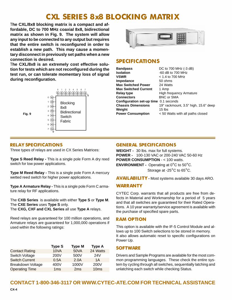
CXL SERIES 8x8 BLOCKING MATRIXThe CXL/8x8 blocking matrix is a compact and af-fordable, DC to 700 MHz coaxial 8x8, bidirectionalmatrix as shown in Fig. 9. The system will allowany input to be connected to any output but requiresthat the entire switch is reconfigured in order toestablish a new path. This may cause a momen-tary disconnect in previously set paths when a newconnection is desired.The CXL/8x8 is an extremely cost effective solu-tion for tests which are not reconfigured during thetest run, or can tolerate momentary loss of signalduring reconfiguration.
SPECIFICATIONSBandpass DC to 700 MHz (-3 dB)Isolation -60 dB to 700 MHzVSWR < 1.4 to 700 MHzImpedance 50 ohmsMax Switched Power 24 WattsMax Switched Current 1 AmpRelay type High frequency ArmatureConnectors BNC or SMAConfiguration set-up time 0.1 secondsChassis Dimensions 19" rackmount, 3.5" high, 15.6" deepWeight 15 lbsPower Consumption < 50 Watts with all paths closed
0
1
2
3
4
5
6
7
0 1 2 3 4 5 6 7
Fig. 9
AVAILABILITY - Most systems available 30 days ARO.
Blocking8x8BidirectionalSwitchFabric

The CXAR Units are 19" rack mounted chassis, and are avail-able as either Mainframes or Expansion Chassis pre-wired toaccept any of the CXR Series of Coaxial Switch Modules. Allchassis have front panel LED indication of latched switch pointsand have the switch modules mounted through the rear panel.
The CT Units are the same but accept 2x1 modules only andare described on the last page.
The CXAR and CT Series are Computer Controlled Coaxial Switching Systems for High Fre-quency Signals up to 1.6 GHz. These systems are typically used to configure 1xN multiplexers.Pre-wired Mainframes and Expansion Chassis will accept a variety of control and switch mod-ules to form the desired configuration.
CXAR AND CT SERIESCOAXIAL SWITCHING SYSTEMS
CXAR/32 Mainframe
2555 Baird Road, Penfield, New York 14526 (585) 381-4740 FAX (585) 381-0475
LED DISPLAYS
MANUAL CONTROL OPTION
CONTROL MODULES
FOR TECHNICAL ASSISTANCE, CONTACT 1-800-346-3117 or WWW.CYTEC-ATE.COM
FEATURES:
BULLETINCXAR & CT/7
• Bandpass from DC to 1.6 GHz with low crosstalk.• Computer Control from IEEE488 BUS, RS232 Serial,
and 10BaseT LAN.• Front Panel Display and Status Feedback to Computer.• Manual Control Option.
CHASSIS
SWITCH MODULESThere are three series of Modules all using relays interconnectedby striplines to give the required characteristic impedance forhigh bandpass.CXR Series use coaxial reed relays and are available with abandpass up to 300 MHz.CXR-G Series use armature relays in a tree configuration andhave a bandpass exceeding 1 GHz.CXR-2A Series use a two pole armature relays to switch bal-anced line signals and have bandpass up to 200 MHz.
SWITCH CHARACTERISTICSCXR Modules are available with Standard Reed Type S or Ter-minating Reed Type T relays.CXR-G Modules use High Power Armature Type G relays.CXR-2A Modules use Two Pole Armature Type 2A relays.
Type S Type T Type G Type 2A
Contact Rating 10VA 3VA 24VA 60VASwitch Voltage 200V 200V 24V 110 VSwitch Current 0.5A 0.25A 1.0A 1.0ABreakdown Voltage 400V 200V 1000V 750VOperating Time 1ms 1ms 10ms 3 msLife Expectancy* 108 108 107 2x10⁵
Manual Controls are available for all chassis types.CXAR/16 and CTC/16 Chassis utilize momentary pushbuttonmanual controls MC/16.CXAR/32, /64 and /128, CTA/32, /64, /128, CTC/ 32, and /64chassis utilize Thumbwheel Manual Controls MC/32, /64 and/128 respectively.
IF-3B or 3C RS232 CONTROL MODULEThis Module has all the RS232 features detailed in Applica-tions Bulletin AP-5. The IF-3B is used on 16 channel chassis.The IF-3C is used on 32 channel chassis.IF-4B or 4C IEEE488 BUS (TALK/LISTEN)This Module has all the IEEE488 features detailed in Applica-tions Bulletin AP-5. The IF-4B is used on 16 channel chassis.The IF-4C is used on 32 channel chassis.IF-5 IEEE488/RS232This Module has both the IEEE488 (Talk/Listen) and the RS232features detailed in Applications Bulletin AP-5. This combina-tion module is used on all 64 or 128 channel chassis.IF-6 LAN INTERFACEThis Module uses TCP/IP to allow control from a Local AreaNetwork as described in AP-5. It is available as an option onany unit with RS232 Control.
CXAR/16, CT/16 and CT/32 Chassis include front panel LEDdisplay of switchpoint status. CXAR/64, CXAR/128 , CT/64 andCT/128 Chassis require one separately purchased CL8 Dis-play module for each eight switch points. This LED indicationis an invaluable aid in program debugging and determining sys-tem status.
CXAR-1
*Life expectancy is at rated load
VMC VIRTUAL MANUAL CONTROL SOFTWAREVMC Software allows the switches to be controlled through aGraphical User Interface. Current version is Windows based.Free with any system purchase.

Fig. 1
Fig. 2
CXAR CHASSIS
CXAR/16 and CXAR/32 MAINFRAMES
CXAR EXPANSION CHASSIS
CXR SERIES SWITCH MODULES
This is the same as the model -1HTbut without termination.
This is an 8x1 two pole configuration asshown in Fig. 3 . Great for switching balancedline 100 ohm differential pairs. It is availablewith isolated BNC's or Twin BNC connectors(Twinax), and uses Type 2A relays.
Fig. 3
HIGH FREQUENCY SPECIFICATIONSCXR/8x1-2A
Bandpass IsolationType MHz at 100 MHzCXR/xxx-1 & 1T 360 60dBCXR/xxx-H1S & H1T 300 70dBCXR/xxx-2A 200 45dB
These Chassis control up to 16 or 32 switch points in any con-figuration. LEDs on the front panel show Switch and PowerStatus. Add Switch Module(s) and a Control Module to com-plete the system. Standard Chassis depth is 12". Chassis heightis typically 3.5". See Drawing Pages following this bulletin..CXAR/64 and CXAR/128 MAINFRAMESThese Chassis control up to 64 or 128 switch points in anyrequired configuration. Add Switch Modules, CL8s and a Con-trol Module to complete the system. The CL8s provide LEDindication of Switch Status through the front panel. StandardChassis depth is 12". Chassis height is determined by SwitchModule selection and configuration but is typically 5.25", 7.0"or 8.75". See Drawing Pages following this bulletin.
The CXAR Chassis are 19" rack mounting units with power supplies and are pre-wired to accept the CXRSeries of Switch Modules. The Switch Modules are mounted so that the connectors protrude through therear panel. The front panel provides LED indication of switch status and optional manual controls. Thefollowing Units are available:
The CXR Series of Switch Modules have Coaxial Relays interconnected by characteristic impedancestriplines to connectors on both bi-directional inputs and outputs. Isolation relays on the commonsreduce crosstalk between interconnected modules.
All CXAR Chassis are available as Expansion Chassis for usewith a MESA Control Chassis. This allows configuration of largeor complex systems with one point of control.
CXAR-2
0
1
2
3
COM
4
5
6
7
ISO1
ISO2
COM
0
1
2
3
4
5
6
7
0
1
2
3
4
5
6
7
COM
CXR/4x1-2AThis is the same 2 wire module but as a 4x1configuration.
CXR/2x1-1S (Form A)
CXR/2x1-2S (Form A)
CXAR/16 With Pushbutton Manual Control
CXAR/128 Rear View
CXR/8x1-1T
This is the same configuration with only fourrelays and without terminations.
This module has single pole Type T relayswhich terminate the inputs to the required im-pedance as shown in Fig. 1 . Energizing theselected relay removes the termination fromthe input and closes the circuit.CXR/8x1-1SThis is the same configuration but without ter-mination.CXR/4x1-1TThis is the same terminated configuration withonly four relays.CXR/4x1-1S
CXR/8x1-1HTThis is a High Isolation Module withrelays which terminates the inputs tothe required impedance and have ad-ditional isolation relays as shown inFig. 2 , which decrease the crosstalkbetween channels by 20dB. Energiz-ing a relay removes the terminating im-pedance and completes the selectedpath.CXR/8x1-HSThis has the same high isolation char-acteristics as the model -1HT but with-out input termination.CXR/4x1-1HTThis has the same characteristics andconfiguration with only four relays.CXR/4x1-1HS
This module switches a common port be-tween A, B or OFF positions as shown in Fig.9 (seen on last page of bulletin). Module usessingle pole, Type S or Type M reed relays.
Same as above with two pole relays.

CXR-G SWITCH MODULES
Fig. 4
CXR/8x1-GThis module is a bidirectional 8x1 configuration as shown inFig. 4 and is available for both 50 or 75 ohm impedance sig-nals.50 ohm models are available with either SMA or BNC connec-tors.Bandpass with SMA connectors is 1.6 GHz (-3dB).Isolation is -50dB at 1 GHz.Bandpass with BNC connectors is 1.0 GHz (-3dB).Isolation is -50dB at 1 GHz.75 ohm models are available with either SMB or BNC connec-tors.Bandpass is 1.2 GHz (-3dB) and isolation is -50dB at 1 GHz.
These modules are designed with Type G relays arranged in a tree configuration as shown in Figs. 4 thru6 with on board logic which selects the appropriate relays to connect the selected input to the common.Only one input can be switched to one output and in the unenergized state input #0 is connected to thecommon except the terminated modules which have an open condition.The Modules are available with 50 ohm or 75 ohm characteristic impedance and with SMA, SMB or BNCconnectors.Combinations of these modules can be assembled to form larger multiplexers or matrices.
CXR/4x1-GThis module is a bidirectional 4x1 configuration using connec-tors 0 thru 3 of Fig. 4 .It is available with the same connectors and has the same band-pass and isolation as the 8x1 module.
CXR/8x1-GT TERMINATED MODULEThis module switches any one of eight 50 or 75 ohm terminatedcoaxial inputs to one output as shown in Fig. 6 . Switching anyinput removes the termination from that input and connects it tothe common.50 ohm models are available with either SMA or BNC connec-tors.Bandpass with SMA connectors is 1.5 GHz (-3dB).Isolation is -60dB at 1 GHz.Bandpass with BNC connectors is 1.0 GHz (-3dB).Isolation is -60dB at 1 GHz.75 ohm models are available with either SMB or BNC connec-tors.Bandpass is 1.0 GHz (-3dB) and isolation is -60dB at 1 GHz.
CXR/4x1-GT TERMINATED MODULEThis module switches any one of four coaxial inputs to com-mon using inputs 0 thru 3 of Fig. 6 .It is available with the same connectors and has the same band-pass and isolation as the 8x1 module.
Fig. 6
0 21 3 4 5 6 7COM
0 21 3 4 5 6 7COM
Fig. 5
CXR/4x2-GThis module switches any two of 4 coaxial ports to the two com-mons as shown in Fig. 5 , and is available for both 50 or 75 ohmimpedance signals.50 ohm modules are available with SMA or BNC connectors.Bandpass with SMA connectors is 1.2 GHz (-3dB)Isolation is -50dB at 1GHz.75 ohm modules are available with SMB or BNC connectors.Bandpass is 800 MHz (-3dB).Isolation is -50dB at 1 GHz.
0 21 3 1 0
CXR/1x8-PD POWER DIVIDER MODULEThis module is a 1x8 power divider intended for use between 5MHz and 500 MHz. The module has a unity gain amplifier sothat all 8 outputs maintain the signal input level (+/- 2 dB) in thegiven frequency range. The module is available with SMA orBNC connectors. A schematic is shown in Fig. 7 .
1
23
45
67
8
Input 1x8PowerDivider
Amp
Fig. 7
CXAR-3

+
-
MODULES
COMIt has a Bandpas s of DC to200 MHz with a 4 volt p/poutput and preset gainsfrom 1 to 16.Impedances on both inputsand outputs can be presetfor impedance matching.
CXBS COAXIAL BUS STRIPS CX/G AMPLIFIERThe Bus Strips are used to connect between CXR Coaxial SwitchModules and are designed for maximum bandpass and mini-mum stub length. They are available to interconnect up to 16modules. Can not be used with Type G or Type 2A Modules.
This amplifier has one BNC input and up to 3 BNC outputs. Itcan be used to restore signal levels or as a Signal Distributor to3 Devices, as shown in Fig. 13 .
Fig. 13
CXR/2x1-2C ( Form C )
A COM BCXR/2x1-1S or -2S ( Form A )This module switches a common portbetween A, B or OFF positions asshown in Fig. 9 . Module uses single ortwo pole, Type S or Type M reed re-lays. Bandpass is 400 MHz (-3 dB).Crosstalk is -60 dB at 5 MHz.
CXR/2x1-G ( Form C )
CXR/2x1-GT ( Form A )
Fig. 11
This module is a version of the CXR/2x1-G module that has the unusedA/B connection terminated into 50 or75 ohm resistors as shown in Fig 11 .This module allows an off state withboth inputs terminated. It is avail-able with 50 or 75 ohm impedance.50 ohm modules use SMA or BNCconnectorsBandpass is 2.5 GHz (-3 dB).Isolation is -60 dB at 1 GHz.75 ohm modules use SMB or BNCconnectors.Bandpass is 1.5 GHz (-3dB).Isolation is -60dB at 1 GHz.
CTC AND CTA A/B SWITCH CHASSISCTC and CTA Chassis are designed to control either Form C A/B switches (no off position) or Form A A/B switches (A, B or Off positions). These chassis are commonly used to sub multiplex larger systems oract as stand alone fail safe redundancy systems. Systems are configured according to whether theyrequire one drive per module (Form C versions) or two drives per module (Form A versions). All chassisare available as Expansion chassis for use with MESA Controllers in larger systems.
CTA CHASSISCTC/16 MAINFRAME OR -E EXPANSION CHASSISControls up to 16 form C switch modules. See Drawing Pagesfollowing this bulletin.CTC/32 MAINFRAME OR -E EXPANSION CHASSISControls up to 32 form C switch modules. See Drawing Pagesfollowing this bulletin.
CTC/64 MAINFRAME OR -E EXPANSION CHASSIS
CTA/32 MAINFRAME OR -E EXPANSION CHASSIS
CTA/64 MAINFRAME OR -E EXPANSION CHASSIS
CTA/128 MAINFRAME OR -E EXPANSION CHASSISControls up to 64 form C switch modules. See Drawing Pagesfollowing this bulletin.
Controls up to 16 form A switch modules. See Drawing Pagesfollowing this bulletin.
Controls up to 32 form A switch modules. See Drawing Pagesfollowing this bulletin.
Controls up to 64 form A switch modules. See Drawing Pagesfollowing this bulletin.
A BCOM
CXR 2x1 (A/B) SWITCH MODULESThe CXR/2x1 Switch Modules may be used in any CXAR or CT Chassis. For large numbers of 2x1's, theCTA and CTC Chassis listed above should be ordered, but any of the 2x1 Modules may be mixed with 8x1or 4x1 modules in the chassis listed in previous sections. Please contact CYTEC for labeling options onchassis that mix multiple module sizes.
This module switches the common toone of two inputs as shown in Fig. 8 .In the unenergized position, the com-mon is connected to input A. It is avail-able with 50 or 75 ohm impedance. 50ohm modules use SMA, SMB or BNCconnectorsBandpass is 2.5 GHz (-3 dB).Isolation is -60 dB at 1 GHz.75 ohm modules use SMB or BNC con-nectors.Bandpass is 1.5 GHz (-3dB).Isolation is -60dB at 1 GHz.
A two pole 2x1, Form C configura-tion as shown in Fig. 10 which allowone input to be switched to two out-puts (A or B). Available with BNC orTwin BNC connectors, and usesType A , Armature relays.
Fig. 8
A COM B
A COM B
Fig. 9
Fig. 10
Fig. 12
CXBS/8 Bus Barshown in drawing
CTC CHASSIS
CXAR-4
2555 Baird Road, Penfield, New York 14526 (585) 381-4740 FAX (585) 381-0475
BULLETINCXM-2
CONTCONTCONTCONTCONTAAAAACT 1-800-346-3117 OR WWWCT 1-800-346-3117 OR WWWCT 1-800-346-3117 OR WWWCT 1-800-346-3117 OR WWWCT 1-800-346-3117 OR WWW.CYTEC.CYTEC.CYTEC.CYTEC.CYTEC-----AAAAATETETETETE.COM FOR TECHNICAL ASSIST.COM FOR TECHNICAL ASSIST.COM FOR TECHNICAL ASSIST.COM FOR TECHNICAL ASSIST.COM FOR TECHNICAL ASSISTANCEANCEANCEANCEANCE
CXM SERIESCXM SERIESCXM SERIESCXM SERIESCXM SERIESMICROWMICROWMICROWMICROWMICROWAAAAAVE SWITVE SWITVE SWITVE SWITVE SWITCHING SYSTEMSCHING SYSTEMSCHING SYSTEMSCHING SYSTEMSCHING SYSTEMS
CYTEC's CXM Series Microwave Switching Systems are computer controlled units that aredesigned to switch 50 ohm coaxial microwave signals. These are passive, bidirectionaldevices. Two basic configurations are available: Nx1 Multiplexers and NxM nonblocking(but not full fanout) Matrices. Bandpass depends on switching topology, but DC to 40 GHz ispossible. Control options include RS232, IEEE488, Ethernet LAN and USB. Manual Controlis also available.
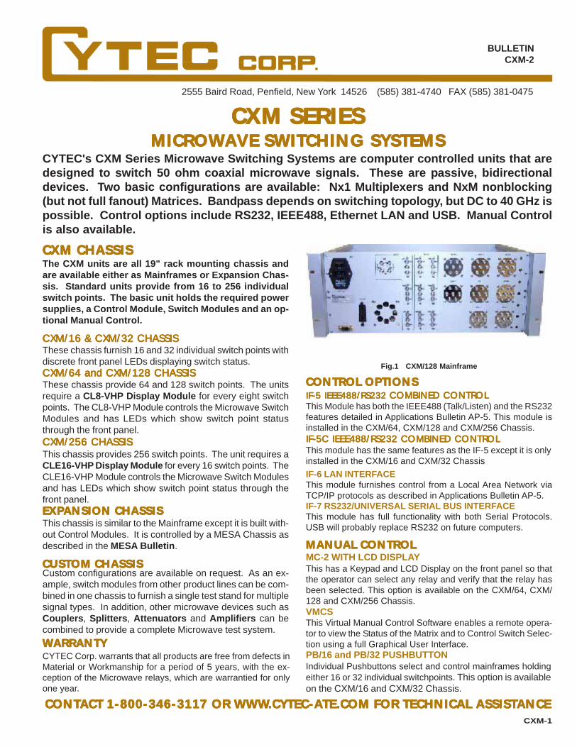
The CXM units are all 19" rack mounting chassis andare available either as Mainframes or Expansion Chas-sis. Standard units provide from 16 to 256 individualswitch points. The basic unit holds the required powersupplies, a Control Module, Switch Modules and an op-tional Manual Control.
CXM CHASSISCXM CHASSISCXM CHASSISCXM CHASSISCXM CHASSIS
Fig.1 CXM/128 Mainframe
CUSTCUSTCUSTCUSTCUSTOM CHASSISOM CHASSISOM CHASSISOM CHASSISOM CHASSISCustom configurations are available on request. As an ex-ample, switch modules from other product lines can be com-bined in one chassis to furnish a single test stand for multiplesignal types. In addition, other microwave devices such asCouplers, Splitters, Attenuators and Amplifiers can becombined to provide a complete Microwave test system.
CONTROL OPTIONSCONTROL OPTIONSCONTROL OPTIONSCONTROL OPTIONSCONTROL OPTIONS
CXM/16 & CXM/32 CHASSISCXM/16 & CXM/32 CHASSISCXM/16 & CXM/32 CHASSISCXM/16 & CXM/32 CHASSISCXM/16 & CXM/32 CHASSISThese chassis furnish 16 and 32 individual switch points withdiscrete front panel LEDs displaying switch status.CXM/64 and CXM/128 CHASSISCXM/64 and CXM/128 CHASSISCXM/64 and CXM/128 CHASSISCXM/64 and CXM/128 CHASSISCXM/64 and CXM/128 CHASSISThese chassis provide 64 and 128 switch points. The unitsrequire a CL8-VHP Display Module for every eight switchpoints. The CL8-VHP Module controls the Microwave SwitchModules and has LEDs which show switch point statusthrough the front panel.
IF-6 LAN INTERFACEThis module furnishes control from a Local Area Network viaTCP/IP protocols as described in Applications Bulletin AP-5.IF-7 RS232/UNIVERSAL SERIAL BUS INTERFACEThis module has full functionality with both Serial Protocols.USB will probably replace RS232 on future computers.
WWWWWARRANTYARRANTYARRANTYARRANTYARRANTYCYTEC Corp. warrants that all products are free from defects inMaterial or Workmanship for a period of 5 years, with the ex-ception of the Microwave relays, which are warrantied for onlyone year.
MANUMANUMANUMANUMANUAL CONTROLAL CONTROLAL CONTROLAL CONTROLAL CONTROL
This has a Keypad and LCD Display on the front panel so thatthe operator can select any relay and verify that the relay hasbeen selected. This option is available on the CXM/64, CXM/128 and CXM/256 Chassis.VMCSThis Virtual Manual Control Software enables a remote opera-tor to view the Status of the Matrix and to Control Switch Selec-tion using a full Graphical User Interface.
MC-2 WITH LCD DISPLAY
PB/16 and PB/32 PUSHBUTTON
CXM-1
CXM/256 CHASSISCXM/256 CHASSISCXM/256 CHASSISCXM/256 CHASSISCXM/256 CHASSISThis chassis provides 256 switch points. The unit requires aCLE16-VHP Display Module for every 16 switch points. TheCLE16-VHP Module controls the Microwave Switch Modulesand has LEDs which show switch point status through thefront panel.
IFIFIFIFIF-5 IEEE488/RS232 -5 IEEE488/RS232 -5 IEEE488/RS232 -5 IEEE488/RS232 -5 IEEE488/RS232 COMBINED CONTROLCOMBINED CONTROLCOMBINED CONTROLCOMBINED CONTROLCOMBINED CONTROLThis Module has both the IEEE488 (Talk/Listen) and the RS232features detailed in Applications Bulletin AP-5. This module isinstalled in the CXM/64, CXM/128 and CXM/256 Chassis.IFIFIFIFIF-5C IEEE488/RS232 COMBINED CONTROL-5C IEEE488/RS232 COMBINED CONTROL-5C IEEE488/RS232 COMBINED CONTROL-5C IEEE488/RS232 COMBINED CONTROL-5C IEEE488/RS232 COMBINED CONTROLThis module has the same features as the IF-5 except it is onlyinstalled in the CXM/16 and CXM/32 Chassis
Individual Pushbuttons select and control mainframes holdingeither 16 or 32 individual switchpoints. This option is availableon the CXM/16 and CXM/32 Chassis.
EXPEXPEXPEXPEXPANSION CHASSISANSION CHASSISANSION CHASSISANSION CHASSISANSION CHASSISThis chassis is similar to the Mainframe except it is built with-out Control Modules. It is controlled by a MESA Chassis asdescribed in the MESA Bulletin.

CXM MULCXM MULCXM MULCXM MULCXM MULTIPLEXERS and MATIPLEXERS and MATIPLEXERS and MATIPLEXERS and MATIPLEXERS and MATRICESTRICESTRICESTRICESTRICES
Fig. 2 CXM/64 Mainframe configured as two independent 29x1 Multiplexers
Fig. 3 4x4 Matrix Using Eight CXM/4x1 Switches
Bidirectional NxM Matrices are assembled by interconnectingthe required number of individual microwave switches asshown in Fig. 3. The matrix is nonblocking, but not full fanout.Nonblocking means that any input can be connected to anyoutput without interrupting a previously set path. When amatrix is not full fanout, an input may be switched to only oneoutput. Matrix configurations from 2x2 to 8x8 or larger arepossible. The switches and interconnects are assembledinside the chassis. The input and output connectors (typi-cally SMAs) are mounted on the rear panel.
�
�
�
��
��
��
�
CXM MACXM MACXM MACXM MACXM MATRICESTRICESTRICESTRICESTRICES
CXM MULCXM MULCXM MULCXM MULCXM MULTIPLEXERSTIPLEXERSTIPLEXERSTIPLEXERSTIPLEXERS
Standard CXM Switch Modules are bidirectional, failsafe, Nor-mally Open switches with a bandpass of DC to 18 GHz. Con-figurations from 1x2 to1x10 are available and SMA connec-tors are standard. Optional features include: Failsafe de-fault to port 1 closed, latching actuators, TNC or N connec-tors, unused input ports terminated to 50 ohms and higherpower handling capability. Standard CXM Switch Modulesare listed below.
SWITSWITSWITSWITSWITCH MODULES SPECIFICACH MODULES SPECIFICACH MODULES SPECIFICACH MODULES SPECIFICACH MODULES SPECIFICATIONSTIONSTIONSTIONSTIONSMicrowave Switch Specifications vary depending on options.The following are typical.
1 GHz 18 GHzInsertion Loss 0.3 dB 0.8dBIsolation -80dB -60dBVSWR <1.2:1 <1.5:1Switching Time <15ms <15msSpecifications are for switches only. Cableing or connec-tor options will decrease certian specifications. Call forspecifications on assembled systems.
CXM SWITCXM SWITCXM SWITCXM SWITCXM SWITCH CH CH CH CH MODULESMODULESMODULESMODULESMODULES
CXM/6x1-F-SMA
Fig. 4 16x1 Multiplexer using five CXM/4x1 Switches
Nx1 Multiplexers are assembled from standard CXM Chas-sis by interconnecting microwave switch modules as shownschematically in Fig. 4. The interconnects are typically semi-rigid coaxial cables and are wired on the rear panel as shownin Fig. 2.
CXM/1X2 SWITCXM/1X2 SWITCXM/1X2 SWITCXM/1X2 SWITCXM/1X2 SWITCH MODULECH MODULECH MODULECH MODULECH MODULE
This is a SPDT Microwave Relay. Op-tions include connector type, higher powerhandling capability and unused port ter-mination and latching versions.CXM/1X4 SWITCXM/1X4 SWITCXM/1X4 SWITCXM/1X4 SWITCXM/1X4 SWITCH MODULECH MODULECH MODULECH MODULECH MODULE
CXM/1X6 SWITCXM/1X6 SWITCXM/1X6 SWITCXM/1X6 SWITCXM/1X6 SWITCH MODULECH MODULECH MODULECH MODULECH MODULEThis is the same as above, but is a SP6Tconfiguration.CXM/1X8 SWITCXM/1X8 SWITCXM/1X8 SWITCXM/1X8 SWITCXM/1X8 SWITCH MODULECH MODULECH MODULECH MODULECH MODULEThis is the same as above, but is a SP8Tconfiguration.
CXM/2x1-F-SMA
CL8-CL8-CL8-CL8-CL8-VHP DISPLAVHP DISPLAVHP DISPLAVHP DISPLAVHP DISPLAY/DRIVER MODULEY/DRIVER MODULEY/DRIVER MODULEY/DRIVER MODULEY/DRIVER MODULEThe CXM/64 and CXM/128 Chassis require one CL8-VHP perevery eight switch points. These modules control the micro-wave switches and have LEDs that show switch point statusand are visible through the chassis front panel.
��������
��
��
��
��
��������
���
�
���
�
CXM-1
CXM/1X10 SWITCXM/1X10 SWITCXM/1X10 SWITCXM/1X10 SWITCXM/1X10 SWITCH MODULECH MODULECH MODULECH MODULECH MODULEThis is the same as above, but is a SP10Tconfiguration.
This is the same as above, but is a SP4Tconfiguration.
CLE16-CLE16-CLE16-CLE16-CLE16-VHP DISPLAVHP DISPLAVHP DISPLAVHP DISPLAVHP DISPLAY/DRIVER MODULEY/DRIVER MODULEY/DRIVER MODULEY/DRIVER MODULEY/DRIVER MODULEThe CXM/256 Chassis require one CLE16-VHP per every 16switch points. These modules control the microwave switchesand have LEDs that show switch point status and are visiblethrough the chassis front panel.

CONTACT 1-800-346-3117, [email protected] OR WWW.CYTEC-ATE.COMFOR TECHNICAL ASSISTANCE AND A COMPLETE CATALOG WITH PRICING!
WARRANTYCYTEC Corp. warrants that all products are free from defectsin Material or Workmanship for a period of 5 years and that allswitches are guaranteed for their rated operations.
DX SERIES 64x64 HIGH SPEED DIGITAL SIGNAL SWITCH MATRIXThe DX Series Digital 64x64 Matrix switches single-ended or differential signals up to 2.0 Gbps. Avail-able for ECL, PECL, LVPECL, LVDS, CML, HDTV ormany other digital signal types. Input and outputtransition boards supply level translations, signalconversion or alternate connector options.
• Available in incremental matrix sizes from 16x16 to 64x64.
• Matched path lengths for low skew.
• Rise and Fall times as fast as 150 psec (20% to 80%).
• Completely nonblocking (any input to any output).
• Full fan-out (any input to several or all outputs).
• Available as dual differential Clock and Data Matrices.
• Jitter correction feature actually improves poor signals.
• Multiple connector options.
• Computer control via GPIB, RS232 or Ethernet.
• Optional front panel Manual Control with LCD display.
• Remote Status Feedback of all switch positions.
• Full five year warranty.
SYSTEM FEATURES:
DX Series 64x64 Differential ECL/PECL Matrix Rear
Prices starting at $20,000.00Availability: 60 days ARO.
This system incorporates an advanced solid state switchfabric that helps restore signal levels, corrects determin-istic jitter and cleans up rise time problems associatedwith wiring and cable runs. Input and Output TransitionModules are also separately available that perform sig-nal conversions in applications which do not requireswitching. Call CYTEC's Sales Department to discussyour application.
NEW SOLID STATE DX SERIES 256x256 DIGITAL SWITCH MATRIX
The Solid State DX/256x256 Solid State Series is avery high density, low cost switch matrix that isdesigned to switch digital TTL or CMOS signalsup to 40 Mbps ( 80 Mbps NRZ ). Input and OutputTransition Modules can be provided for differen-tial signals or level conversion allowing for signaltypes such as RS232, RS422 or almost any digitaldata stream. Optional Patch or Breakout Panelsfurnish almost any connector type specified by theend user. The Matrix may be configured formultiwire switching, such as a Dual Clock and DataMatrix or Rx and Tx signals.DX/256x256 Solid State Switch Matrix
Prices starting at $20,000.00Availability: 60 days ARO.SYSTEM FEATURES:
• Available in incremental sizes from 64x64 to 256x256.
• Completely nonblocking (any input to any output).
• Full fan-out (any input to several or all outputs).
• Available as dual differential Clock and Data Matrices.
• Multiple connector options.
• Computer control via GPIB, RS232, or Ethernet.
• Optional front panel Manual Control with LCD display.
• Remote Status Feedback of all switch positions.
• Full five year warranty.
SOFTWAREFree Example/Driver programs are available for most modernOperating systems. Platforms include: C, Visual Basic, Java,LabView and LabWindows.
• Applications include TTL, CMOS, RS232 and RS422 data.

2555 Baird Road, Penfield, New York 14526 (585) 381-4740 FAX (585) 381-0475
BULLETINDX-1
CONTACT 1-800-346-3117 OR WWW.CYTEC-ATE.COMFOR TECHNICAL ASSISTANCE
DX SERIESDX SERIESDX SERIESDX SERIESDX SERIESSOLID STSOLID STSOLID STSOLID STSOLID STAAAAATE DIGITTE DIGITTE DIGITTE DIGITTE DIGITAL SWITAL SWITAL SWITAL SWITAL SWITCHING SYSTEMSCHING SYSTEMSCHING SYSTEMSCHING SYSTEMSCHING SYSTEMS
CYTEC's DX Series Switching Systems are based on solid state switch fabric.The Standard DX system is designed to switch TTL, CMOS, LVTTL, IRIG, RS232and RS422. Input and output buffers are used to convert to RS422 and/or RS232signal levels. The DX is capable of switching data rates to 80 Mbps NRZ. TheDX Matrix is a nonblocking, full fan-out configurations from 64x64 up to 256x256.Control options include RS232/ IEEE488, LAN or LCD Keypad Manual Control.
The DX/256X256 Series are 19" rack mounting units andare built as either Mainframe or Expansion Chassis. TheSolid State Digital Matrix is modular, capable of beingexpanded from a 64x64 to a 256x256 by adding the de-sired number of input and output modules. The con-figurations occur in 64 channel increments so typicalconfigurations will be 64x448, 128x384, 256x256, etc.Other possible configurations such as dual 12x12 clockand data matrices or multi chassis clock and data sys-tems are also available. The DX Series Matrix is com-pletely nonblocking and full fan-out.
DX/256X256 CHASSISDX/256X256 CHASSISDX/256X256 CHASSISDX/256X256 CHASSISDX/256X256 CHASSIS
IFIFIFIFIF-6 LAN INTERF-6 LAN INTERF-6 LAN INTERF-6 LAN INTERF-6 LAN INTERFAAAAACECECECECE
DX/256x256 Mainframe Rear View
CUSTCUSTCUSTCUSTCUSTOM CHASSISOM CHASSISOM CHASSISOM CHASSISOM CHASSISCustom configurations are available upon request. Most cus-tom systems wire out the rear panel Input/Output connec-tions to a required connector type that is different from thestandard 64 pin male header or 78 pin female D Connectors.This wiring is priced on the basis of labor and materials.
MANUAL CONTROLMANUAL CONTROLMANUAL CONTROLMANUAL CONTROLMANUAL CONTROL
This Virtual Manual Control Software allows a remote operatorusing a PC to view matrix Status and control switches using afull Graphical User Interface.
MCMCMCMCMC-2 WITH LCD DISPLA-2 WITH LCD DISPLA-2 WITH LCD DISPLA-2 WITH LCD DISPLA-2 WITH LCD DISPLAYYYYY
VMCSVMCSVMCSVMCSVMCS
CONTROL MODULESCONTROL MODULESCONTROL MODULESCONTROL MODULESCONTROL MODULESDX/256X256 MAINFRAMEDX/256X256 MAINFRAMEDX/256X256 MAINFRAMEDX/256X256 MAINFRAMEDX/256X256 MAINFRAMEThe Standard Mainframes are built with power supplies, userspecified Control Module and optionally Keypad LCD DisplayManual Control. The system is completely modular by add-ing the desired number of DX/64 Input and Output SwitchModules defined on page 2 of the bulletin.
The expansion chassis is identical to the mainframe in sizeand function. The expansion chassis, however, is built with-out a dedicated control module, manual control or power sup-plies. Instead, it is designed to be both powered and con-trolled by one of CYTEC's MESA Control Chassis detailed inthe MESA Bulletin. Ribbon Expansion Cables connect theexpansion chassis to the MESA.
DX/256x256-E EXPANSION CHASSISDX/256x256-E EXPANSION CHASSISDX/256x256-E EXPANSION CHASSISDX/256x256-E EXPANSION CHASSISDX/256x256-E EXPANSION CHASSIS
IFIFIFIFIF-5 IEEE488/RS232 CONTROL MODULE-5 IEEE488/RS232 CONTROL MODULE-5 IEEE488/RS232 CONTROL MODULE-5 IEEE488/RS232 CONTROL MODULE-5 IEEE488/RS232 CONTROL MODULEThis module provides remote control via both RS232 Serialand IEEE488 Talk/Listen interfaces as detailed in Applica-tions Bulletin AP-5.
This optional module allows control over a 10BaseT EthernetLocal Area Network via TCP/IP protocols as described in Ap-plications Bulletin AP-5.
This local control supplies a front panel Keypad and LCD Dis-play that lets the operator control any switch and verify switchstatus.
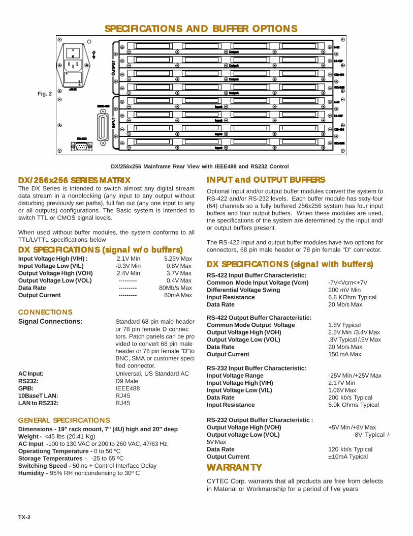
SPECIFICASPECIFICASPECIFICASPECIFICASPECIFICATIONS AND BUFFER OPTIONSTIONS AND BUFFER OPTIONSTIONS AND BUFFER OPTIONSTIONS AND BUFFER OPTIONSTIONS AND BUFFER OPTIONS
DX/256x256 SERIES MADX/256x256 SERIES MADX/256x256 SERIES MADX/256x256 SERIES MADX/256x256 SERIES MATRIXTRIXTRIXTRIXTRIX
DX/256x256 Mainframe Rear View with IEEE488 and RS232 Control
INPUT and OUTPUT BUFFERSINPUT and OUTPUT BUFFERSINPUT and OUTPUT BUFFERSINPUT and OUTPUT BUFFERSINPUT and OUTPUT BUFFERSOptional Input and/or output buffer modules convert the system toRS-422 and/or RS-232 levels. Each buffer module has sixty-four(64) channels so a fully buffered 256x256 system has four inputbuffers and four output buffers. When these modules are used,the specifications of the system are determined by the input and/or output buffers present.
The RS-422 input and output buffer modules have two options forconnectors, 68 pin male header or 78 pin female "D" connector.
RS-422 Input Buffer Characteristic:Common Mode Input Voltage (Vcm) -7V<Vcm<+7VDifferential Voltage Swing 200 mV MinInput Resistance 6.8 KOhm TypicalData Rate 20 Mb/s Max
Fig. 2
TX-2
The DX Series is intended to switch almost any digital streamdata stream in a nonblocking (any input to any output withoutdisturbing previously set paths), full fan out (any one input to anyor all outputs) configurations. The Basic system is intended toswitch TTL or CMOS signal levels.
When used without buffer modules, the system conforms to allTTL/LVTTL specifications below
DX SPECIFICADX SPECIFICADX SPECIFICADX SPECIFICADX SPECIFICATIONS (signal w/o buffers)TIONS (signal w/o buffers)TIONS (signal w/o buffers)TIONS (signal w/o buffers)TIONS (signal w/o buffers)
DX SPECIFICADX SPECIFICADX SPECIFICADX SPECIFICADX SPECIFICATIONS (signal with buffers)TIONS (signal with buffers)TIONS (signal with buffers)TIONS (signal with buffers)TIONS (signal with buffers)Input Voltage High (VIH) : 2.1V Min 5.25V MaxInput Voltage Low (VIL) -0.3V Min 0.8V MaxOutput Voltage High (VOH) 2.4V Min 3.7V MaxOutput Voltage Low (VOL) --------- 0.4V MaxData Rate --------- 80Mb/s MaxOutput Current --------- 80mA Max
CONNECTIONSCONNECTIONSCONNECTIONSCONNECTIONSCONNECTIONS
GENERAL SPECIFICAGENERAL SPECIFICAGENERAL SPECIFICAGENERAL SPECIFICAGENERAL SPECIFICATIONSTIONSTIONSTIONSTIONS
Signal Connections: Standard 68 pin male headeror 78 pin female D connectors. Patch panels can be provided to convert 68 pin maleheader or 78 pin female "D"toBNC, SMA or customer specified connector.
AC Input: Universal, US Standard ACRS232: D9 MaleGPIB: IEEE48810BaseT LAN: RJ45LAN to RS232: RJ45
RS-422 Output Buffer Characteristic:Common Mode Output Voltage 1.8V TypicalOutput Voltage High (VOH) 2.5V Min /3.4V MaxOutput Voltage Low (VOL) .3V Typical /.5V MaxData Rate 20 Mb/s MaxOutput Current 150 mA Max
RS-232 Input Buffer Characteristic:Input Voltage Range -25V Min /+25V MaxInput Voltage High (VIH) 2.17V MinInput Voltage Low (VIL) 1.06V MaxData Rate 200 kb/s TypicalInput Resistance 5.0k Ohms Typical
RS-232 Output Buffer Characteristic :Output Voltage High (VOH) +5V Min /+8V MaxOutput voltage Low (VOL) -8V Typical /-5V MaxData Rate 120 kb/s TypicalOutput Current ±10mA Typical
Dimensions - 19" rack mount, 7" (4U) high and 20" deepWeight - <45 lbs (20.41 Kg)AC Input -100 to 130 VAC or 200 to 260 VAC, 47/63 Hz,Operationg Temperature - 0 to 50 ºCStorage Temperatures - -25 to 65 ºCSwitching Speed - 50 ns + Control Interface DelayHumidity - 95% RH noncondensing to 30º C
WARRANTYWARRANTYWARRANTYWARRANTYWARRANTYCYTEC Corp. warrants that all products are free from defectsin Material or Workmanship for a period of five years

2555 Baird Road, Penfield, New York 14526 (716) 381-4740 FAX (716) 381-0475
BULLETINFX/FO-2
CONTACT 1-800-346-3117 OR WWW.CYTEC-ATE.COMFOR TECHNICAL ASSISTANCE
FX and FO SERIESFIBER OPTIC SWITCHING SYSTEMS
CYTEC's FX Series of Fiberoptic Switching Systems are nonblocking, full fan-out optoelectricalswitch matrices available in configurations from 8x8 to 64x64. Different Transmitter/ReceiverModule combinations provide for 820, 1310 or 1550 nanometer wavelengths, with data ratesto 622 Mb (OC-12/STM-4).The FO Series are passive, optical systems that use mechanical fiberoptic relays. Individualswitches, 1xN Multiplexers or NxM Matrices can be supplied. Many connector types and bothsingle and multimode fiber options can be specified. Control options include RS232, IEEE488and Ethernet LAN. Manual Control is also available.
At the heart of the FX Chassis is a differential ECL SolidState Matrix routing data at rates up to 1.2 Gbs in both anonblocking (any input to any output) and full fan-out (oneinput to many or all outputs) arrangement. The FX/16x16 isused for 8x8 and 16x16 matrices, while the larger FX/64x64can supply up to 64 individual inputs and outputs. See Fig 1.The Chassis also holds, as needed, the Fiberoptic Receiverand Transmitter Modules. The user then specifies the Con-trol Module and optionally a Manual Control. This modular-ized design allows systems to be configured according tothe end user's specific design requirements.
OPTOELECTRICAL SWITCHING'S ADVANTAGES:
Fig. 1
FX/16x16 and FX/64x64 CHASSIS
STANDARD CONFIGURATIONS
FX SERIES TRANSMITTER & RECEIVER MODULES
These Modules are designed to be used with single modefiberoptic cables. Wavelengths of either 1310 nm or 1550 nmare switched. Data rates of 50 Mb/sec to 700 Mb/sec arehandled.
TYPICAL APPLICATIONS INCLUDE:
It is cost effective.One input can be distributed to many or all outputs.Modal dispersion is minimized.Amplitude restored on weak signals.No mechanical mirrors or switches to fail.
•••••
Programmable Routing in Fiber Wiring Closets.Multiport Protocol Analysis for Networks and Test.Signal Distribution for Communications and Test.Automated Patch Panels.
••••
01
64210
2
15
16 to 64
16 to 64FiberOutputs
Fiber Inputs
Matrices with 16, 32, 48 and 64 Inputs are possible.Output numbers of 16, 32, 48 and 64 are also possible. Anycombination of Inputs and Outputs and be provided, for ex-ample a 16x64 or 48x32. One Input can connect to any, sev-eral or all Outputs.
Fig. 1 FX SeriesTopology
FX/16x16-820-100 Mainframe
FX/16X16 CHASSISMatrices available in 8x8, 8x16, 16x8 or 16x16 configurations.One Input can connect to any, several or all Outputs.FX/64X64 CHASSIS
Custom systems are available upon request. Please contactone of our Applications Engineers for assistance.
CUSTOM CONFIGURATIONS
FX/FO-1
FX/100-820 & -1310-MM MULTIMODE SERIESThese low cost Transmitter and Receiver Modules are designedto switch either 820 nm or 1310 nm signals into multimode50/125 or 62.5/125 um fiberoptic cables. Data rates up to 155Mb/sec (NRZ) are handled.FX/600-1310 & -1550-SM SINGLEMODE SERIES

TRANSCEIVER MODULE OPTIONS
Includes the FXR-100-820 Receiver and FXT-100-820Transmitter Modules for 820 nm wavelengths as well asthe FXT-100-1310 Transmitter and FXR/100-1310 ReceiverModules for 1310 nm. Eight individual input or outputchannels are supplied by each Receiver or Transmittermodule. Multimode cables at data rates up to 155 Mb/sec (NRZ) are supported. Transmitters are ALGaAs LEDs,Receivers are PIN Photododes.
FXT/100-820Connectors SMA or STWavelength Range 795 - 860Typical (nm) 820
Glass Fiber Types 50/125(Core/Cladding, um) 62.5/125
100/140
Data Rates Min. 5 Kb/sec(NRZ) Max. 155 Mb/sec
FXR Input Power Min. -20 dBm Overload @ Max. -8 dBm
FXT Output PowerInto 62.5/125 um fiber -15 dBmInto 50/125 um fiber -17 dBm
Bit Error Rate: 1 x 10⁻⁹
PRICING AND AVAILABILITYAssemble systems by selecting the appropriate FX Chas-sis, the desired Control Module and input Receiver andoutput Transmitter Modules as needed.See Published Price List for current pricing on all FXProducts.
Most systems available 30 - 60 days ARO
FX/16X16 & FX/64X64 SPECIFICATIONS
Physical 19" Rack MountingDepth 20"Height / WeightFX/16x16 5.25" (3U) < 25 lbs.FX/64x64 Consult Factory
Connections Fiber connectors (SMA, ST, SC, FC),AC Mains Power and Remote ControlInterface are on rear panel.
ENVIRONMENTAL
FX/100-820-MM and FX/100-1310-MM FX/600-1310 and FX/600-1550 SERIES
Operating Temp. 0o to 55o CStorage Temp. 0o to 70o CHumidity 95% RH non-condensing to 30o C
FXT/100-1310 ST or SC 1270 - 1370 1310
50/125 62.5/125
5 Kb/sec 155 Mb/sec
-28 dBm -11 dBm
-14 dBm -17 dBm
1 x 10⁻⁹
FXT/600-1310Connectors ST, SC, FCWavelength Range 1261 - 1360Typical (nm) 1310
[short reach]
Glass Fiber Types Single Mode
Data Rates Min. 50 MbMax. 700 Mb/sec
(NRZ, 25 MHz - 350 MHz)
FXR Input Power Min. -29 dBm Overload @ Max. -6 dBm(FXR Input Signal 1100 - 1600 nm)
FXT Output Power -11 dBm(Higher Powers Available)
Bit Error Rate: 1 x 10⁻¹⁰
FXT/600-1550 ST, SC, FC 1480 - 1580 1550 [long reach]
Single Mode
50 Mb/sec 700 Mb/sec
-29 dBm -6dBm
-11dBm
1 x 10⁻¹⁰
Includes the FXR-600-1310/1550 Receiver and either theFXT-600-1310 or FXT-600-1550 Transmitter Modules. Trans-mitter and Receiver Modules are each eight channels.Transmitters Modules transmit at the single wavelengthof either 1310 nm or 1550 nm and data rates of 50 Mb to700 Mb/sec (NRZ, nominal) with Laser Diodes (Class 1Safety Compliant). Receiver Modules support 1100 nmthru 1600 nm.
Figure 2 FX/16x16-600-1310 Mainframe Rear View:
AC Input Selectable 100-130 or 200-240Volts AC, 50-60 Hz.
Max. AC Power 100 Watts for FX/16x16 Matrix400 watts for FX/64x64
FX/FO-2
SPECIFICATIONS: SPECIFICATIONS:

FO SERIESPASSIVE FIBER OPTIC SWITCHING SYSTEMS
CYTEC's new FO Series Passive Fiberoptic Switching Systems are computer controlled chassisthat are designed to switch standard fiberoptic wavelengths of 850 nm, 1310 nm and 1550nm. Multimode 62.5/125 um switches are available for 850 nm and 1310 nm wavelengths,while Singlemode 9/125 um switches are available for 1310 nm and 1550 nm. Passive, bidirec-tional Moving Fiberoptic Switches are used that show insertion losses as low as 0.10 dB forMultimode and 0.25 dB for Singlemode switches. Three configurations are available: Indi-vidual Switches, Nx1 Multiplexers and NxM nonblocking (but not full fan-out) Matrices. Con-trol options include RS232, IEEE488 and TCP/IP Ethernet LAN. Manual Control is optionallyavailable.
FO/16 with Pushbutton Manual Control
The FO Series are all 19" rack mounting chassisand are available either as Mainframes or Expan-sion Chassis. Standard chassis provide from eightto 32 individual switch points. All chassis havefront panel LEDs for a visual indication of switchpoint status. Input and output signal connectorsprotrude from the chassis rear. FC, SC and STfiberoptic connectors are standard.STANDARD CHASSISStandard units are built with the required power supplies, auser specified Control Module and optionally a Manual Con-trol. Control Module selections are shown on the last page ofthis bulletin. The system is completed by specifying the num-ber and type of FO Series Fiberoptic Switches describedbelow.FO/8, FO/16 & FO/32 CHASSIS
CUSTOM CHASSISCustom configurations are available on request. As examples,switch modules can be wired out to nonstandard rear panelfiberoptic connectors; switch modules can also be wired to-gether with fiberoptic interconnects to furnish small nonblock-ing matrices (2x2, 2x4, 4x4, etc.)FO SERIES PASSIVE SWITCH MODULESThe FO Fiber Optic Switches utilizes a “moving fiber” designconcept to achieve highly accurate direct fiber to fiber connec-tions. Currently available in 1x2, dual 1x2 and dual 1x2nonblocking configurations. Also available in both Singleand Multimode versions as well as Normal and Low Losstypes. Insertion Loss is as low as 0.25 for Singlemode and0.10 dB for Multimode switches.
FO Series Switch Module
FO SERIES SWITCH SPECIFICATIONS (Individual Modules without connectors) :
Connectors ST, SC, FC Standard (others available on request)
Wavelength Range 850 nm, 1310 nm Singlemode(nominal) 1310 nm, 1550 nm MultimodeGlass Fiber Types 9/125 um Singlemode
62.5/125 um Multimode
Insertion Loss 0.25 dB SinglemodeLow Loss Type, typ. 0.10 dB MultimodeInsertion Loss 0.8 dB SinglemodeNormal Loss Type, typ. 0.6 dB MultimodeBack Reflection -60 dB TypicalCrosstalk -70 dB MaximumRepeatablility 0.01 dBSwitch Time 10 milliseconds TypicalOptical Power +20 dBm max. Singlemode
+ 23 dBm max. Multimode
FO/1x2Switch Module
FO/2x2Crossover Module
FO/2(1x2) Blocking Switch Module
These chassis furnish 8, 16 or 32 individual switch points.One front panel LED is assigned to each switch point anddisplays status.
FO CHASSIS
FX/FO-3

Fig. 4 FO/8 Mainframe with two FO/2x1 Switches Installed
This module has all the RS232 features detailed in Applica-tions Bulletin AP-5.
This control module has all the IEEE488 features detailed inApplications Bulletin AP-5
This module uses TCP/IP protocols to allow control from anEthernet LAN as described in Bulletin AP-5.
MANUAL CONTROL
This Virtual Manual Control Software gives the operator theability to remotely Open and Close switches as well as ob-serve system Status. Control is via a full Graphical User In-terface (GUI).
Individual Pushbuttons select and control mainframes holdingeither eight or 16 individual switchpoints.
Mainframe chassis holding 32 switchpoints are built with op-tional Thumbwheel Manual Controls.
Bidirectional Nx1 Multiplexers are assembled from standardFO Chassis by interconnecting Fiberoptic Switch Modules asshown schematically in Fig. 5 . The interconnects arefiberoptic cables and are usually wired externally, on the rearpanel. Internally wired systems may be ordered as an option.
FO SERIES MULTIPLEXERS
FO SERIES MATRICESBidirectional NxM Matrices are assembled by interconnect-ing the required number of individual FO Series fiberopticswitches as shown in Fig. 6 . The Matrix is non-blocking (butnot full fan-out) and any input can connect to any single out-put. The switches and interconnects are placed inside thechassis, while the input and output fiberoptic connectors aremounted on the rear panel.
Fig. 5 8x1 Multiplexer using Seven FO/2x1 Switches
Fig. 6 4x2 Matrix using four two FO/2x1 andtwo FO/Crossover Switches.
INPUTS
1
2
3
4
OUTPUTS
1
2
INP
UT
S
1
8
OUTPUT
CONTROL MODULES
LED DISPLAYSFO/8, FO/16 and FO/32 Chassis are built with individual, dis-crete front panel LEDs that show switchpoint status. TheseLEDs are an invaluable aid in program debugging and systemtroubleshooting.
This module has both the IEEE488 (Talk/Listen) and the RS232features detailed in Applications Bulletin AP-5.
AVAILABILITYMost systems are available 30 - 45 Days ARO.
WARRANTYCYTEC Corp. warrants that all products are free from defectsin Materials and Workmanship for a period of 5 years and thatall switches are guaranteed for their rated Operational Life-time.
SOFTWARE
IF-3C RS232 SERIAL
IF-4C IEEE488 BUS (TALK/LISTEN)
IF-5C IEEE488/RS232 COMBINED CONTROL
IF-6 LAN INTERFACE
Example and Driver Programs are available for most commonWindows-based programming languages, including LabView,LabWindows and Visual Basic.
VMCS SOFTWARE
MC/8 & MC/16 PUSHBUTTON
MC/32-TW THUMBWHEEL
FX/FO-4

2555 Baird Road, Penfield, New York 14526 (585) 381-4740 FAX (585) 381-0475
GX SERIESGX SERIESGX SERIESGX SERIESGX SERIESGROUP SWITGROUP SWITGROUP SWITGROUP SWITGROUP SWITCHING MACHING MACHING MACHING MACHING MATRICES and MULTRICES and MULTRICES and MULTRICES and MULTRICES and MULTIPLEXERSTIPLEXERSTIPLEXERSTIPLEXERSTIPLEXERS
DDDDDAAAAATTTTTA ANALA ANALA ANALA ANALA ANALYSIS SYSTEMYSIS SYSTEMYSIS SYSTEMYSIS SYSTEMYSIS SYSTEMVibration Data collected on four Tape Recorders are to be ana-lyzed by two Instruments. Each Tape Recorder has 28 chan-nels. All 28 channels from any of the four Tape Recordersmust be switched as a group to either of the two Instrumentsas shown below. The data frequency is 0 to 300 kHz, and thewiring is coaxial cable with BNC connectors.
���������
������ ��������
���������
������ ��������
���������
������ ��������
���������
������ ��������
������������������ ������!�""#$%����������
�������� �������� �������� ��������
�������� ��������
��& �'(�� �� ��& �'(�� �)
GROUP MULTIPLEXERS switch any one of several Groups of Input signals to a single OutputGroup, or the reverse, that is, one Input Group to one of several Output Groups.GROUP MATRICES switch selected Groups of Inputs to selected Output Groups in an NxM matrixconfiguration.Remote computer control via IEEE488 and RS232 is standard. Optional computer controls in-clude Parallel TTL, Ethernet LAN and USB. Manual Controls are also optionally available on boththe GX Mainframes or the GX Control Units.
BULLETINGX-3
Standard CYTEC Switch Modules are available that can switch 8, 16 or 32 sig-nal wires simultaneously. These modules can be custom configured as GroupSwitches to handle large number of signals per switched crosspoint.
The GX Series is used when the required number of sig-nals to be switched exceeds that available in StandardProduct such as RS Series Matrices and Multiplexers,which can switch up to 25 wires per crosspoint and aredesigned for Data Communications Signals.
CONTCONTCONTCONTCONTAAAAACT 1-800-346-3117 OR WWWCT 1-800-346-3117 OR WWWCT 1-800-346-3117 OR WWWCT 1-800-346-3117 OR WWWCT 1-800-346-3117 OR WWW.CYTEC.CYTEC.CYTEC.CYTEC.CYTEC-----AAAAATETETETETE.COM FOR TECHNICAL ASSIST.COM FOR TECHNICAL ASSIST.COM FOR TECHNICAL ASSIST.COM FOR TECHNICAL ASSIST.COM FOR TECHNICAL ASSISTANCEANCEANCEANCEANCE
The switch module selected is the LX8B/4x2, a four Input totwo Output coaxial switch module with BNC Inputs and Out-puts. Twenty-eight Modules driven in parallel are needed toswitch the 28 coaxial signals in a 4x2 matrix configuration.These modules can be assembled in two GX/16-E Expan-sion Chassis and controlled from one GX/8 Control Chassis.
The Group Switch concept is best illustrated by a practical application such as the one shownbelow.
For assistance in selecting the best productseries and configuration for your application,please contact our Technical Sales Departmentat the phone number listed below.
GX-3
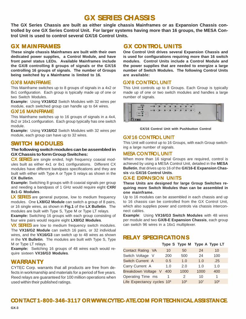
GX SERIES CHASSISGX SERIES CHASSISGX SERIES CHASSISGX SERIES CHASSISGX SERIES CHASSISThe GX Series Chassis are built as either single chassis Mainframes or as Expansion Chassis con-trolled by one GX Series Control Unit. For larger systems having more than 16 groups, the MESA Con-trol Unit is used to control several GX/16 Control Units.
These single chassis Mainframes are built with their owndedicated power supplies, a Control Module, and havefront panel status LEDs. Available Mainframes includethe GX/8 controlling 8 groups of signals or the GX/16controlling 16 groups of signals. The number of Groupsbeing switched by a Mainframe is limited to 16.
GX/8 MAINFRAMEGX/8 MAINFRAMEGX/8 MAINFRAMEGX/8 MAINFRAMEGX/8 MAINFRAMEThis Mainframe switches up to 8 groups of signals in a 4x2 or8x1 configuration. Each group is typically made up of one ortwo Switch Modules.Example: Using VX16/G2 Switch Modules with 32 wires permodule, each switched group can handle up to 64 wires.
GX/16 MAINFRAMEGX/16 MAINFRAMEGX/16 MAINFRAMEGX/16 MAINFRAMEGX/16 MAINFRAMEThis Mainframe switches up to 16 groups of signals in a 4x4,8x2 or 16x1 configuration. Each group typically has one switchmodule.Example: Using VX16/G2 Switch Modules with 32 wires permodule, each group can have up to 32 wires.
GX/16 Control Unit with Pushbutton Control
WWWWWARRANTYARRANTYARRANTYARRANTYARRANTYCYTEC Corp. warrants that all products are free from de-fects in workmanship and materials for a period of five years.Reed relays are guaranteed for 100 million operations whenused within their published ratings.
GX MAINFRAMESGX MAINFRAMESGX MAINFRAMESGX MAINFRAMESGX MAINFRAMES GX CONTROL UNITSGX CONTROL UNITSGX CONTROL UNITSGX CONTROL UNITSGX CONTROL UNITSOne Control Unit drives several Expansion Chassis andis used for configurations requiring more than 16 switchmodules. Control Units include a Control Module andthe power supplies that are needed to energize a largenumber of Switch Modules. The following Control Unitsare available:
GX/8 CONTROL UNITGX/8 CONTROL UNITGX/8 CONTROL UNITGX/8 CONTROL UNITGX/8 CONTROL UNIT
GX/16 CONTROL UNITGX/16 CONTROL UNITGX/16 CONTROL UNITGX/16 CONTROL UNITGX/16 CONTROL UNIT
This Unit controls up to 8 Groups. Each Group is typicallymade up of one or two switch modules and handles a largenumber of signals.
This Unit will control up to 16 Groups, with each Group switch-ing a large number of signals.
MESA CONTROL UNITMESA CONTROL UNITMESA CONTROL UNITMESA CONTROL UNITMESA CONTROL UNITWhen more than 16 signal Groups are required, control isachieved by using a MESA Control Unit, detailed in the MESABulletin, that drives up to 16 of the GX/16-E Expansion Chas-sis via GX/16 Control Units.
GXGXGXGXGX-E EXP-E EXP-E EXP-E EXP-E EXPANSION UNITSANSION UNITSANSION UNITSANSION UNITSANSION UNITSThese Units are designed for large Group Switches re-quiring more Switch Modules than can be assembled inone mainframe.Up to 16 modules can be assembled in each chassis and upto 16 chassis can be controlled from the GX Control Unit,which also supplies power and controls via chassis intercon-nect cables.Example: Using VX16/G3 Switch Modules with 48 wiresper module and two GX/8-E Expansion Chassis, each groupcan switch 96 wires in a 16x1 multiplexer.
SWITSWITSWITSWITSWITCH MODULESCH MODULESCH MODULESCH MODULESCH MODULES
CX SCX SCX SCX SCX SERIESERIESERIESERIESERIES are single ended, high frequency coaxial mod-ules built as either 4x1 or 8x1 configurations. Different CXmodules have different bandpass specifications and they arebuilt with either with Type A or Type S relays as shown in theCX Bulletin.Example: Switching 8 groups with 8 coaxial signals per groupand needing a bandpass of 1 GHz would require eight CXR/8x1-G Modules.LX LX LX LX LX SERIESSERIESSERIESSERIESSERIES are general purpose, low to medium frequencymodules. One LX8/G2 Module can switch a group of 8 pairs,or 16 single wires, as shown in Fig.1 of the LX Bulletin. Themodules are built with Type S, Type M or Type LT relays.Example: Switching 16 groups with each group consisting offour wire pairs would require eight LX8/G2 Modules.VXVXVXVXVX SERIES SERIES SERIES SERIES SERIES are low to medium frequency switch modules.The VX16/G2 Module can switch 16 pairs, or 32 individualwires, and the VX16/G3 can switch up to 48 wires as shownin the VX Bulletin. The modules are built with Type S, TypeM or Type LT relays.Example: Switching 16 groups of 48 wires each would re-quire sixteen VX16/G3 Modules.
RELARELARELARELARELAY SPECIFICAY SPECIFICAY SPECIFICAY SPECIFICAY SPECIFICATIONSTIONSTIONSTIONSTIONSType S Type M Type A Type LT
Contact Rating VA 10 50 24 10Switch Voltage V 200 500 24 100Switch Current A 0.5 1.0 1.0 .25Carry Current A 1.0 2.0 1.0 1.0Breakdown Voltage V 400 1000 1000 400Operating Time ms 1 2 10 1Life Expectancy cycles 108 108 107 108
CONTCONTCONTCONTCONTAAAAACT 1-800-346-3117 OR WWWCT 1-800-346-3117 OR WWWCT 1-800-346-3117 OR WWWCT 1-800-346-3117 OR WWWCT 1-800-346-3117 OR WWW.CYTEC.CYTEC.CYTEC.CYTEC.CYTEC-----AAAAATETETETETE.COM FOR TECHNICAL ASSIST.COM FOR TECHNICAL ASSIST.COM FOR TECHNICAL ASSIST.COM FOR TECHNICAL ASSIST.COM FOR TECHNICAL ASSISTANCEANCEANCEANCEANCE.GX-3
The following switch modules can be assembled inGX Chassis to form Group Switches:

FEAFEAFEAFEAFEATURESTURESTURESTURESTURES:::::
The HXV Series of Computer Controlled Switching Systems are used in High Voltage and HIPOTapplications. They consist of pre-wired Mainframes and Expansion Chassis which hold selectedSwitch Modules needed to furnish the required Matrix or Multiplexer configuration.
HXV SERIESHXV SERIESHXV SERIESHXV SERIESHXV SERIES HIGH VHIGH VHIGH VHIGH VHIGH VOLOLOLOLOLTTTTTAAAAAGE / HIPOGE / HIPOGE / HIPOGE / HIPOGE / HIPOT SWITT SWITT SWITT SWITT SWITCHING SYSTEMSCHING SYSTEMSCHING SYSTEMSCHING SYSTEMSCHING SYSTEMS
HXV/32 Mainframe with PushButton Manual Control
2555 Baird Road, Penfield, New York 14526 (585) 381-4740 FAX (585) 381-0475
LED DISPLALED DISPLALED DISPLALED DISPLALED DISPLAYSYSYSYSYS
MANUAL CONTROL OPTIONSMANUAL CONTROL OPTIONSMANUAL CONTROL OPTIONSMANUAL CONTROL OPTIONSMANUAL CONTROL OPTIONS
CONTROL MODULESCONTROL MODULESCONTROL MODULESCONTROL MODULESCONTROL MODULESIFIFIFIFIF-5 IEEE488/RS232-5 IEEE488/RS232-5 IEEE488/RS232-5 IEEE488/RS232-5 IEEE488/RS232
HXV/32 Mainframes have relay status LED Displays built intothe front panels.HXV/96 and HXV/128 Mainframes and Expansion Chassisrequire one CL8 Display Module to drive each switch module.CL8 LEDs are visible at the front panel. These display mod-ules must be purchased in addition to the switch modules.
Hot switches up to 3500 volts or 3 amps, carries 5000volts and 5 amps.Computer Control from IEEE488 and RS232; EthernetLAN or USB are optional.Front Panel Display of Switchpoint Status with Sta-tus Feedback to the controlling computer.Manual Controls optionally available.
CHASSISCHASSISCHASSISCHASSISCHASSISAll HXV Chassis are standard 19" rack mountingwidth and 15.6" deep. The following chassis areavailable:HXV/32 Mainframe -- Holds up to four HXV Switch Modules.HXV/96 Mainframe -- Holds up to 12 HXV Switch Modules.HXV/128 Mainframe -- Holds up to 16 HXV Switch ModulesHXV/96-E and HXV/128-E Expansion Chassis -- Used forbuilding larger systems. Up to 16 Expansion Chassis can becontrolled from one MESA Control Chassis shown in the MESABulletin.Chassis Heights:HXV/32 = 5.25" HXV/96 = 7" HXV/128 = 10.5"
SWITCH MODULESSWITCH MODULESSWITCH MODULESSWITCH MODULESSWITCH MODULESHXV/8x1-A -- Built with eight Form A (SPST) Normally OpenRelays arranged as an 8x1 multiplexer.HXV/8x1-B -- Has eight Form B (SPDT) Normally Closed Re-lays.HXV/8-KA -- Provides eight individual Form A Relays.HXV/8-KB -- Eight individual Form B Relays.HXV/4x2 -- Has eight Form A Relays arranged as a 4x2 matrix.
RELARELARELARELARELAY SPECIFICAY SPECIFICAY SPECIFICAY SPECIFICAY SPECIFICATIONSTIONSTIONSTIONSTIONS
BULLETINHXV-4
•
•
•
•
Pushbutton Manual Controls are optionally available for theHXV/32 Mainframes. (Specify PB/32). Optional Keypad LCDDisplay Manual Controls are offered for the HXV/96 and HXV/128 Mainframes. (Specify MC-2).
HXV-1
WARRANTYWARRANTYWARRANTYWARRANTYWARRANTYCYTEC Corp. warrants that all products are free from defectsin workmanship and materials for a period of five years. Reedrelays are guaranteed for 100 million operations when usedwithin their published specifications.
CONTACT 1-800-346-3117 or WWW.CYTEC-ATE.COM FOR TECHNICAL ASSISTANCE
Contact Rating 200 WattsSwitch Voltage 3500 VoltsSwitch Current 3.0 AmpsCarry Current 5.0 AmpsBreakdown Voltage 5000 Volts RMSOperating Time 3.0 msecLife Expectancy 100 million operations mechanical
SOFTWARESOFTWARESOFTWARESOFTWARESOFTWAREExample/Driver programs are available free of charge, writtenin most common application languages, including LabView,LabWindows, Visual Basic and HP Vee.
CONNECTOR OPTIONS:CONNECTOR OPTIONS:CONNECTOR OPTIONS:CONNECTOR OPTIONS:CONNECTOR OPTIONS:SHV - Similar to BNCs. Highest safety.BP - Banana Plug & Binding Post Type. Lowest Cost.
This Module has both the IEEE488 (Talk/Listen) and the RS232features detailed in Applications Bulletin AP-5.IFIFIFIFIF-6 LAN INTERF-6 LAN INTERF-6 LAN INTERF-6 LAN INTERF-6 LAN INTERFAAAAACECECECECEThis Module uses TCP/IP to allow control from a Local AreaNetwork as detailed in Applications Bulletin AP-5.IFIFIFIFIF-7 EXTERNAL USB/RS232 INTERF-7 EXTERNAL USB/RS232 INTERF-7 EXTERNAL USB/RS232 INTERF-7 EXTERNAL USB/RS232 INTERF-7 EXTERNAL USB/RS232 INTERFAAAAACECECECECEThis external cable plugs into a USB port on the controllingcomputer at one end and the Cytec Mainframe's RS232 Porton the other. Allows control via USB at up to 19,200 bps.

HXV/32 Mainframe (rear panel)
HXV CHASSISHXV CHASSISHXV CHASSISHXV CHASSISHXV CHASSIS
HXV/32 MAINFRAMESHXV/32 MAINFRAMESHXV/32 MAINFRAMESHXV/32 MAINFRAMESHXV/32 MAINFRAMES
HXV/96-E and HXV/128-E EXPHXV/96-E and HXV/128-E EXPHXV/96-E and HXV/128-E EXPHXV/96-E and HXV/128-E EXPHXV/96-E and HXV/128-E EXPANSION CHASSISANSION CHASSISANSION CHASSISANSION CHASSISANSION CHASSIS
HXV SERIES SWITCH MODULESHXV SERIES SWITCH MODULESHXV SERIES SWITCH MODULESHXV SERIES SWITCH MODULESHXV SERIES SWITCH MODULES
HXV/8x1-A or -BHXV/8x1-A or -BHXV/8x1-A or -BHXV/8x1-A or -BHXV/8x1-A or -BThis switch module has eight Form A (Normally Open) or FormB (Normally Closed) relays arranged in an 8x1 configurationas shown in Fig. 1. A screw terminal connector is built intothe module so that the COM connections may be wired to-gether inside the chassis to form larger multiplexers.
Fig. 1
HXV/4x2-AHXV/4x2-AHXV/4x2-AHXV/4x2-AHXV/4x2-AThis switch module is built with eight Form A (SPST) relaysarranged in a 4x2 matrix configuration as shown in Fig. 2.Built-in screw terminal connectors allow the two COM con-nections to be wired together among multiple modules withinthe chassis to form larger matrices such as 8x2, 16x2, etc.
Fig. 2
� � � � ��� � � ���� ����
The HXV Chassis are 19" rack mounting chassis that are pre-wired to hold the HXV Series of SwitchModules. Mainframe chassis include built-in power supplies. The Switch Modules mount so that thesignal I/O connectors protrude through the chassis' rear panel. Power and control connectors are alsomounted on the rear panel. The front panel has LEDs that show power ON and switch status. Optionalmanual controls also mount on the front panel. The following units are available:
This Chassis controls 32 switch points. A number of differentswitching configurations are possible. Add the required SwitchModule(s) and a Control Module to complete the system. Stan-dard Chassis depth is 15.6", and Chassis height 5.25". Notethat the HXV/32 is not available as an expansion chassis.
HXV/96 and HXV/128 MAINFRAMESHXV/96 and HXV/128 MAINFRAMESHXV/96 and HXV/128 MAINFRAMESHXV/96 and HXV/128 MAINFRAMESHXV/96 and HXV/128 MAINFRAMESThese Chassis control 96 or 128 switch points respectively. Avariety of configurations are possible. CL8 Display/Driver Mod-ules drive the associated Switch Modules and provide LEDindication of switch status. Add Switch Modules, CL8s and aControl Module to complete the system. Standard Chassisdepth is 15.6". The HXV/96 is 7" high, while the HXV/128 is10.5" high. Purchasing larger Mainframes only partially filledallows for cost-effective future expansion.
HXV/96 and HXV/128 units are also built as expansion chas-sis for use with a MESA Control Chassis shown in the MESABulletin. Multiple expansion chassis allow the configurationof large or complex systems having one point of control, whichresults in cost savings. Expansion Chassis do not includepower supplies or control modules. Add the required switchmodules and CL8 Display/Driver Modules as needed to com-plete the system.
The HXV Series of Switch Modules are built with special High Voltage Reed Relays that switch up to3500 Volts and carry 5000 Volts. Applications include HiPot testing, insulation breakdown testing andother extreme voltage requirements. External signal connectors are either SHV coaxial or Banana Plugs.The modules can be wired together internally to furnish larger configurations while eliminating externalconnections. For example, chassis can be supplied pre-wired as 32x1, 96x1 or 128x1 multiplexers, or ,16x2, 48x2 or 64x2 matrices.
HXV/8-KA or -KBHXV/8-KA or -KBHXV/8-KA or -KBHXV/8-KA or -KBHXV/8-KA or -KBThis module has eight individual Form A (Normally Open) orForm B (Normally Closed) relays wired out to 16 connectorsas shown in Fig. 3. It requires a double slot in the chassis.
Fig. 3
� � � � � �
HXV-1
HXV/8x1-A Switch Module
CYTEC Corp. takes pride in building custom sys-tems that meet non-standard or special customerspecifications. Please call 1-800-346-3117 or [email protected] to contact an Application En-gineer and discuss details.HXV/8-KA Switch Module
CUSTOM SYSTEMSCUSTOM SYSTEMSCUSTOM SYSTEMSCUSTOM SYSTEMSCUSTOM SYSTEMS

JX/256 Multiplexer with Keypad Manual Control and Display
JX-1
Size - Standard 19" rack mounting chassis, 5.25" high and16" deep.Prewired Backplane accepts 16 Switch Modules and oneControl Module. The Backplane includes signal bussingso that the Switch Modules can be interconnected up to a512x1 Multiplexer or 256x2 Matrix.JX/256 Mainframe - This is a stand alone unit with itsown Power Supplies controlled from any one of the ControlModules. It can also be supplied with an optional ManualControl and Front Panel LCD Display.Optional Dual Supplies - Standard power supplies allowup to 150 relays to be closed simultaneously. Dual sup-plies can be provided for applications requiring over 150relays being closed at one time.JX/256-E Expansion Chassis - These chassis obtaintheir power and control from the MESA Series Control Unitsas detailed in the MESA Bulletin and any number ofExpansion Chassis can be interconnected to make up largemultiplexers.JX/256-E-PS Expansion Chassis w/Power Supply -These Expansion Chassis can be provided with PowerSupplies for applications which require closing over 150relays within the same chassis simultaneously. Call anddiscuss your application to determine if you need thisoption.-W Option - The Mainframes or Expansion Chassis canbe supplied with all signals wired out to special, userspecified connectors on the rear panel. Consult Factoryfor pricing.
JX SERIES MATRIX/MULTIPLEXERSFOR
DATA ACQUISITION AND AUTOMATIC TEST
Typical applications include:
• Data Acquisition
• Component Testing
• Bed of Nails Testers
• Cable Testers
Five Year WarrantyModular Construction with expandability by addingExpansion Chassis and Switch Modules.Control Modules are available for Control from Com-bined IEEE488 BUS/RS232 Serial Port, 10BaseTEthernet LAN or 16 BIT TTL Port.Switch Modules with 1, 2, 3 or 4 pole relays.
Low voltage switching to 1 microvolt.Low current switching to 1 picoamp.High current switching to 8 amp.Breakdown voltage to 1000 volt.
Digital I/O Modules having 16 TTL or Power Drivers.Multiplex Mode - The Unit can be operated as a singleor dual multiplexer.Matrix Mode - Any number of Switches can be selectedat the same time.Manual Controls - Switches can be selected by op-tional front panel keypad with LCD display.Status - Status feedback to the controller verifies theposition of the relays.
2555 Baird Road, Penfield, New York 14526 (585) 381-4740 Fax (585) 381-0475
This compact and economically priced Series can be used as either Multiplexers, Matricesor Individual Switches. As Multiplexers, they can be used as a single multiplexer to switch alarge number of inputs or outputs to one commpon port , or as a dual multiplexer to switchbetween either of two common ports. As Matrices, any number of switches can be selectedand wired out in the required configuration. Individual Relays are available as SPST or SPDTwith standard, mercury wetted or power relays.
FEATURES
MAINFRAMES AND EXPANSION CHASSIS•
•
•
•
•
•
•
••
•
•
••
•
•
•
BULLETINJ-8

SERIES JX16 SWITCH MODULES
JX-2
Fig. 4
JX16/KP SWITCH MODULE
Fig. 5
JX16/KPC SWITCH MODULE
Fig. 6
JX16/L1 AND /L2 SWITCH MODULES
This Series of Switch Modules has 16 relays configured asMultiplexers as shown in Figs. 1 & 2. These modules canbe used as separate muxes or bussed together on the back-plane to form one multiplexer as large as 256x1.Bandpass is 20 MHz (-3dB) and Isolation is less than 60dBat 1 MHz when used in a 256x1 Mux.
JX16/L SWITCH MODULESThis Series of Switch Modules has 16 discrete relays withall contacts brought out to connectors accessible from thethe chassis rear. Each relay has a Bandpass exceeding 20MHz (-3dB) and Crosstalk less than 56dB at 1 MHz.
JX16/K SWITCH MODULES
JX 32/L2 SWITCH MODULE
Fig. 1
Fig. 2
Fig. 3
JX16/4(4x1)-1 and -2 SWITCH MODULESThis module has 16 single or two pole relays arranged as four4x1 multiplexers as shown in Fig. 3 . The muxes may be jum-pered to the backplane to form up to a 256x1 mux or two 128x1muxes. It is available with Type S, M or LT relays.
JX16/K1 SWITCH MODULEThis module has 16 single pole relays as shown in Fig. 4 withboth sides of all relays brought out to a 34 pin Header connec-tor. The module is available with Type S or Type M relays.
JX16/KC SWITCH MODULE
The JX16 Switch Modules plug into the JX/256 Mainframe and Expansion Chassis and typically are builtwith 16 relays and their associated solid state controls, including Status feedback.The Modules are available with high reliability reed relays that have a guaranteed life of 100 millionoperations and with the option of either Type S - Standard Dry Reed, Type M - Mercury Wetted Reed orType LT - Low Thermal Reed. They are also available with Armature type Power Relays for switching upto 2000 VA power or 8 amps current.There are three basic types of Modules: JX16/L for Multiplexing configurations, JX16/K for discreterelays, and JX16/AB for x2 Matrix configurations.
This module has 16 single or two pole relays as shown in Fig. 1with signal inputs wired to a 34 pin header connector. The two8x1 muxes may be jumpered together to form a 16x1. Theoutputs are available on a 10 pin header connector or can bejumpered to the card edge connector which plugs into thebackplane. It is available with Type S, M or LT relays.
This module has 32 two pole relays as shown in Fig. 2 withsignal inputs wired to two 34 pin header connectors. The two16x1 muxes can be jumpered together to form one 32x1 mux.The outputs are available on a 10 pin header connector or canbe jumpered to the card edge connector which plugs into thebackplane. It is available with Type A relays only.
This module has 16 single pole, Type P power relays as shownin Fig. 4 with both sides brought out to a 37 pin D type connec-tor.
HEADER CONNECTOR
HEADERCONNECTOR
BAC
KPLA
NE
HEADERCONNECTOR
HEADER CONNECTOR
BAC
KPLA
NE
0 1 2 3 4 5 6 7
8 9 10 11 12 13 14 15
0 1 2 3 4 5 6 7
8 9 10 11 12 13 14 15
0 1 2 3 4 5 6 7
This module has 16 single pole, double throw relays as shownin Fig. 5 with all contacts brought out to a 50 pin Header con-nector. The module is available with either Type CS or TypeCM relays.
JX16/KCA SWITCH MODULEThis module has 16 single pole, double throw relays as shownin Fig. 5 with all contacts brought out to a 50 pin Header con-nector. The module is available with Type A relays only.
This module has 8 single pole, double throw discrete Form CType P power relays shown in Fig. 6 with all contacts broughtout to screw terminal connectors.
HEADER CONNECTOR Pins 0-15 Top
HEADERCONNECTOR
BA
CK
PLA
NE
HEADER CONNECTOR Pins 16-31 Btm

JX-3
JX16/AB SWITCH MODULES
JX16/AB-1 SWITCH MODULE
JX32/AB-1 SWITCH MODULE
Fig. 7
Fig. 8
JX16/AB-4 FOUR POLE MODULE
JX16/PROTO-I/O MODULE
Type P and PC Relays are armature relays for high powerswitching with the following specifications:AC Rating 2000VADC Rating 150 WMaximum Switch Voltage 380Volt RMSBreakdown Voltage 1000Volt RMSMaximum Switch Current 8AmpOperate Time 10msec
Fig. 10
SWITCH SPECIFICATIONS
A/B TYPE MODULE APPLICATIONS
Fig. 9
These Modules typically have 16 relays configured as an8x2 Matrix so that any of 8 inputs can be switched to eitherof 2 outputs. Bandpass is better than 20 MHz (-3dB) andIsolation is less than 40 dB at 100 kHz when used in aJX/256 chassis.
This Module has sixteen single pole relays arranged in an 8x2configuration so that any of the eight inputs can be switched toeither output A or B as shown in Fig. 7 . The eight inputs arewired to a 16 pin header connector with two pins wired to eachinput for convenience in daisy chaining modules. The A and Boutputs are available on a 10 pin header connector, or they canbe bussed to the backplane as shown in Fig. 7 . The module isavailable with Type S or Type M reed relays.
This Module has thirty-two single pole relays arranged in a 16x2configuration so that any of the sixteen inputs can be switchedto either output A or B as shown in Fig. 8 . The sixteen inputsare wired to a 34 pin header connector with two pins assignedto each input for convenience in daisy chaining modules, andtwo pins are grounds. The A and B outputs are available on a10 pin header connector, or they can be bussed to the back-plane as shown in Fig. 8 . The module is available with Type Sor Type M reed relays.
This Module has 16 four pole relays with signal inputs wired toa 37 pin D type connector as shown in Fig. 9 . The outputs Aand B are wired to the edge connector which plugs into thebussed motherboard. The module is available with Type S orType M relays.Note: This is the only module without Status Feedback.
For Cable, Backplane or Bareboard testing, the requirement isto select any two points and check for continuity. It is also nec-essary to check between one point and all others.
This module, shown in Fig. 10 , plugs into the JX Series back-plane and has logic to control 16 TTL Outputs or Relay DriverOutputs and 16 TTL compatible inputs.TTL Outputs are three state, Non Inverting Buffer/Line Driverswith output capability of 16 LSTTL loads.Relay Driver Outputs are High Voltage, High Current, OpenCollector Drives with diode suppression for energizing Induc-tive loads.Data Inputs are Data Selector/Multiplexers with TTL compat-ible Inputs and three state output to the JX/256 Mainframe. Thiscan be used to interrogate the status of the TTL or Relay DriverOutputs.Connections may be wired to the 50 pin header supplied onthe module or wired directly to the board.
The following types of relays are available:Type S are dry reed switches for Instrumentation Level Sig-nals.Type LT has a thermal offset of less than 1 microvolt for verylow voltage applications.Type M has mercury wetted contacts with higher power capa-bility.Type CS and CM are form C versions of Type S & Type M.Type A are two pole armature
All reed switches have a rated life greater than 100 million op-erations when used within the following specifications:
10 PinHeader 16 Pin
Header
A Bus
B Bus
Backpla
ne
10 PinHeader 34 Pin
Header
Backpla
ne
A Bus
B Bus
A Bus
B Bus
37 PinD-Type
RELAY TYPE S< M CS CM AContact Rating 10VA 50VA 3VA 25VA 30VASwitching Voltage 200V 500V 200V 200V 110VSwitching Current 0.5A 1.0A 0.25A 1.0A 1.0ACarrying Current 1A 2A 1A 2A 1ABreakdown Voltage 300V 1000V 200V 1000V 750VOperate Time 1ms 2ms 1ms 2ms 3ms

JX-4
CONTROL MODULES
IF-J1 16 BIT TTL PORT
IF-J5 COMBINED IEEE488/RS232 MODULE
MC-2 MANUAL CONTROL WITH DISPLAY
APPLICATIONS
KELVIN BRIDGE MEASUREMENTS
Fig. 12
Fig. 13
Plug in modules can control the JX/256 Mainframe fromeither TTL Port, Combined IEEE488 BUS / RS232 SerialBUS or 10Base-T Ethernet LAN.The Control Module selects any switch in the Mainframeand Latches or Unlatches the switch in either the Matrixor Multiplexer Mode and can also request the Status ofselected switches.In the Matrix Mode, any number of relays can be selectedand Latched or Unlatched.In the Multiplex Mode, only one relay is selected andLatched. All others are automatically Unlatched.
This Module has 16 TTL compatible lines for Relay Select, ModeSelect, Status Switch and Strobe.
This Module has both IEEE488 BUS Control with Talk/Listenfeatures and RS232 Serial Control. The Control Functions aredetailed in Applications Bulletin AP-5.
IF-6 LAN/RS232 INTERFACEThis module interfaces between the Local Area Network andthe RS232 Control Modules using TCP/IP commands as de-scribed in Applications Bulletin AP-5.
This Manual Control Option has a Keypad and LCD Display onthe front panel. The operator can select any switch and verifythe switch Status via the display.
MATING CONNECTORS
J4C 4 pin connector using individual crimp pinsJ8C 8 pin connector using individual crimp pinsJ10R 10 pin IDC type ribbon cable connectorJ10C 10 pin connector using individual crimp pinsJ16R 16 pin IDC type ribbon cable connectorJ16C 16 pin connector using individual crimp pinsJ20R 20 pin IDC type ribbon cable connectorJ20C 20 pin connector using individual crimp pinsJ34R 34 pin IDC type ribbon cable connectorJ34C 34 pin connector using individual crimp pinsJ37R 37 pin D type ribbon cable connectorJ37C 37 pin D type crimp pin connectorJ50R 50 pin IDC type ribbon cable connectorJ50C 50 pin connector using individual crimp pins
Fig. 11
In this application, the Scanner is required to sequentially selectany one of a number of inputs and switch it to a measuring in-strument such as a DVM.For low level signals, or in noisy environments requiring highcommon mode rejection, it is advisable to use two pole relaysswitching both the Hi and Lo input of the DVM as shown in Fig.11.
For extremely low level signals such as thermocouples, the LTtype relays with less than 1 microvolt of thermal offset should beused. For additional noise prevention, the shields from the pairsof wires can be switched to the Instrument Guard as shown inFig. 12 .
For very low impedance measurements using a four wire bridge,it is necessary to switch both Stimuli and Sense lines to eachside of the device under test as shown in Fig. 12 . This requiresa total of 4 poles switching with two pole relays as shown in Fig.13. Any two points can be selected, and the impedance be-tween these points measured.
VMCSThis Virtual Manual Control Software enables a remote opera-tor to view the Status of the Matrix and to Control Switch Selec-tion using a full Graphical User Interface.
DVMHI
LO
DVMHI
LOGUARD
BRIDGE
+-
STIMULUS
+-
SENSE
MANUAL CONTROLS
CONTACT 1-800-346-3117 or WWW.CYTEC-ATE.COM FOR TECHNICAL ASSISTANCE
CYTEC Corp. warrants that all products are free from de-fects in workmanship and materials for a period of 5 years.Reed relays are guaranteed for 100 million operations whenused within their published specifications.
WARRANTY
SCANNER/MULTIPLEXERS
SOFTWAREVisit our website for free software, drivers for common platformsand program expamples.

BULLETINLX-6
2555 Baird Road, Penfield, New York 14526 (585) 381-4740 Fax (585) 381-0475
LX SERIESLX SERIESLX SERIESLX SERIESLX SERIESGENERAL PURPOSE SWITGENERAL PURPOSE SWITGENERAL PURPOSE SWITGENERAL PURPOSE SWITGENERAL PURPOSE SWITCHING MACHING MACHING MACHING MACHING MATRICESTRICESTRICESTRICESTRICES
FOR AFOR AFOR AFOR AFOR AUTUTUTUTUTOMAOMAOMAOMAOMATIC TESTTIC TESTTIC TESTTIC TESTTIC TEST, INSTRUMENT, INSTRUMENT, INSTRUMENT, INSTRUMENT, INSTRUMENTAAAAATION AND CONTROLTION AND CONTROLTION AND CONTROLTION AND CONTROLTION AND CONTROL
LX MAINFRAMESLX MAINFRAMESLX MAINFRAMESLX MAINFRAMESLX MAINFRAMESThe LX Series Mainframes are 19" rack mounting chassis, 3.5"high and 15.6" deep, with power supplies and motherboardsthat hold up to 16 Switch and Display Modules and one Con-trol Module. Signal connectors are located at the unit's rearpanel and LED display is visible through the front panel.The following Mainframes are standard:
LX-1
The LX Series are high reliability, low cost, versatile Switching Systems. A modular design conceptis used. Interchangeable Control Modules, Switch Modules and Display Modules can be assembled intoMatrices, Multiplexers or Individual Switch Point configurations. All chassis have full front panel LEDdisplays. Status Feedback from all switches is provided. A variety of switch modules are offered, includ-ing those designed to handle the following signals: Coaxial RF, Low Level with a DC offset less than 1microvolt, High Voltages up to 1500 volts, and High Current up to 8 amps.The Control Modules available are IEEE488 Bus, RS232 Serial, TTL Parallel Port, 10Base-T EthernetLAN, and Universal Serial Bus. Manual Controls are optionally available.
LXA GENERAL PURPOSELXA GENERAL PURPOSELXA GENERAL PURPOSELXA GENERAL PURPOSELXA GENERAL PURPOSEThese are the most versatile units, accepting any of the LXSeries Switch Modules and capable of furnishing Multiplexers,Matrices or Individual Switches as needed.LXB MALXB MALXB MALXB MALXB MATRICESTRICESTRICESTRICESTRICESThese mainframes hold the LXB Series Switch Modules andfurnish several prewired Matrix configurations.
LX EXPLX EXPLX EXPLX EXPLX EXPANSION CHASSISANSION CHASSISANSION CHASSISANSION CHASSISANSION CHASSISThese units have the same motherboards as the mainframesbut do not have built-in power supplies or control modules.They are powered and controlled from a single MESA ControlMainframe as described in the MESA Bulletin. Larger con-figurations can be created from up to 16 Expansion Chassis,and different product series can be combined to supply a com-plete system for switching a variety of signals.
LXLXLXLXLX-----W WIRED UNITSW WIRED UNITSW WIRED UNITSW WIRED UNITSW WIRED UNITSAll Mainframes and Expansion Chassis can be supplied in15.6" deep chassis with modules wired out to user specifiedconnectors. Please contact our Applications Engineers formore information.
SWITCH MODULESSWITCH MODULESSWITCH MODULESSWITCH MODULESSWITCH MODULESThere are two basic switch module series: The LX8 Seriesand LXB Series. All modules have signal connectors ac-cessed at the chassis rear panel.LX8 SERIESLX8 SERIESLX8 SERIESLX8 SERIESLX8 SERIESThese modules are used in the LXA Mainframes and includethe following:LX8/G2 Switch Modules are built with 8, two pole relays andhave signal inputs and outputs arranged so that they can bewired to supply several matrix configurations.LX8/G1P Switch Modules are built with 8, single pole TypeP Power Relays. These are designed for high power and cur-rent applications and have signal connectors that can be wiredto provide several matrix configurations.LX8/K Switch Modules have 8, Normally Open single polerelays with inputs and outputs wired to a signal connector.LX8/OD Driver Modules have 8, optoisolated Output Driversand are used to drive external logic or electrical loads.LX8/ID Input Detection Modules have 8, optoisolated InputDetectors that are capable of sensing DC or AC voltage levels.LXB SERIESLXB SERIESLXB SERIESLXB SERIESLXB SERIESThese Switch Modules are used in the LXB Matrices and in-clude the following:LXB/2(1x4) Switch Modules have 8, single or double polerelays arranged as two 1x4 matrices.LXB/4(1x2) Switch Modules have 8, single or double polerelays arranged as four 1x2 matrices.LXB/(1x8) Switch Modules have 8, single or double polerelays arranged as one 1x8 matrix.
LX/128 Mainframe with Thumbwheel Manual Control
������������
�������
����������
��
���
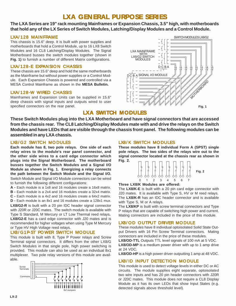
LXA GENERAL PURPOSE SERIESLXA GENERAL PURPOSE SERIESLXA GENERAL PURPOSE SERIESLXA GENERAL PURPOSE SERIESLXA GENERAL PURPOSE SERIES
LXA/128 MAINFRAMELXA/128 MAINFRAMELXA/128 MAINFRAMELXA/128 MAINFRAMELXA/128 MAINFRAME
LXA/128-LXA/128-LXA/128-LXA/128-LXA/128-W WIRED CHASSISW WIRED CHASSISW WIRED CHASSISW WIRED CHASSISW WIRED CHASSIS
LX8/G2-R is built with a 20 pin IDC header signal connectorwith J20R or J20C mates. The switch module is available withType S Standard, M Mercury or LT Low Thermal reed relays.LX8/G2-E has a card edge connector with J20 mates and isrecommended for higher voltages when using Type M Mercuryor Type HV High Voltage reed relays.
LX8/K SWITLX8/K SWITLX8/K SWITLX8/K SWITLX8/K SWITCH MODULESCH MODULESCH MODULESCH MODULESCH MODULES
Fig. 1
Fig. 2
LX-2
This chassis is 15.6" deep. It is built with power supplies andmotherboards that hold a Control Module, up to 16 LX8 SwitchModules and 16 CL8 Latching/Display Modules. The SignalMotherboard busses the switch modules together (shown inFig. 1) to furnish a number of different Matrix configurations.
LXA/128-E EXPLXA/128-E EXPLXA/128-E EXPLXA/128-E EXPLXA/128-E EXPANSION CHASSISANSION CHASSISANSION CHASSISANSION CHASSISANSION CHASSISThese chassis are 15.6" deep and hold the same motherboardsas the Mainframe but without power supplies or a Control Mod-ule. Each Expansion Chassis is powered and controlled via aMESA Control Mainframe as shown in the MESA Bulletin.
Mainframes and Expansion Units can be supplied in 15.6"deep chassis with signal inputs and outputs wired to userspecified connectors on the rear panel.
LX8/G2 SWITLX8/G2 SWITLX8/G2 SWITLX8/G2 SWITLX8/G2 SWITCH MODULESCH MODULESCH MODULESCH MODULESCH MODULES
These Switch Modules plug into the LXA Motherboard and have signal connectors that are accessedfrom the chassis rear. The CL8 Latching/Display Modules mate with and drive the relays on the SwitchModules and have LEDs that are visible through the chassis front panel. The following modules can beassembled in any LXA chassis.
� ���
�������� ���������
����������������������������� ���
�� � �
�������
���
������������ ��
The LXA Series are 19" rack mounting Mainframes or Expansion Chassis, 3.5" high, with motherboardsthat hold any of the LX Series of Switch Modules, Latching/Display Modules and a Control Module.
These modules have 8 individual Form A (SPST) singlepole relays. The two sides of the relays wire out to thesignal connector located at the chassis rear as shown inFig. 2.
Each module has 8, two pole relays. One side of eachrelay wires to the module's rear panel connector, andthe other side wires to a card edge connector whichplugs into the Signal Motherboard. The motherboardbusses together the Switch Modules and a Signal I/OModule as shown in Fig. 1. Energizing a relay connectsthe path between the Switch Module and the Signal I/O.
These modules have 8 individual optoisolated Solid State Out-put Drivers with 16 Pin Screw Terminal connectors. Matingconnectors are included in the price of these modules.LX8/OD-TTL Outputs TTL level signals of 100 mA at 5 VDC.LX8/OD-MP is a medium power driver with up to 1 amp driveat 24 VDC.LX8/OD-HP is a high power driver outputting 1 amp at 48 VDC.
LX8/ID INPUT DETECTION MODULELX8/ID INPUT DETECTION MODULELX8/ID INPUT DETECTION MODULELX8/ID INPUT DETECTION MODULELX8/ID INPUT DETECTION MODULEThis module is used to detect voltage levels in either DC or ACcircuits. The module supplies eight separate, optoisolatedtwo wire inputs and has 20 pin header connectors with J20Ror J20C mates. This module does not require a CL8 DisplayModule as it has its own LEDs that show Input States (e.g.detected signals above threshold level).
Three LX8/K Modules are offered:The LX8/K-E is built with a 20 pin card edge connector withJ20 mates. It is available with Type S, HV or M reed relays.The LX8/K-R has an IDC header connector and is availablewith Type S, M or A relays.The LX8/KP is built with screw terminal connectors and TypeP relays that are capable of switching high power and current.Mating connectors are included in the price of this module.
� � � � � � � �
LXA SWITCH MODULESLXA SWITCH MODULESLXA SWITCH MODULESLXA SWITCH MODULESLXA SWITCH MODULES
LX8/OD OUTPUT DRIVER MODULELX8/OD OUTPUT DRIVER MODULELX8/OD OUTPUT DRIVER MODULELX8/OD OUTPUT DRIVER MODULELX8/OD OUTPUT DRIVER MODULE
Switch Module and Signal I/O Module connectors can be wiredto furnish the following different configurations:A - Each module is a 1x8 and 16 modules create a 16x8 matrix.B - Each module is a 2x4 and 16 modules create a 32x4 matrix.C - Each module is a 4x2 and 16 modules create a 64x2 matrix.D - Each module is an 8x1 and 16 modules create a 128x1 mux.
LX8/G1PLX8/G1PLX8/G1PLX8/G1PLX8/G1P-----ST POWER SWITST POWER SWITST POWER SWITST POWER SWITST POWER SWITCH MODULECH MODULECH MODULECH MODULECH MODULEThis module is built with 8, Type P Power relays and ScrewTerminal signal connectors. It differs from the other LX8/GSwitch Modules in that single pole, high power switching isprovided. This module can also be used as an individual 8x1multiplexer. Two pole relay versions of this module are avail-able.
��� !"#$%&
�'%$(�$%")*+,&
�-""-*&

LXB MALXB MALXB MALXB MALXB MATRIX SERIESTRIX SERIESTRIX SERIESTRIX SERIESTRIX SERIES
Fig. 3Fig. 4
LXB/2(16x4) MAINFRAMELXB/2(16x4) MAINFRAMELXB/2(16x4) MAINFRAMELXB/2(16x4) MAINFRAMELXB/2(16x4) MAINFRAME LXB/64x2 MAINFRAMELXB/64x2 MAINFRAMELXB/64x2 MAINFRAMELXB/64x2 MAINFRAMELXB/64x2 MAINFRAME
LX-3
The LXB Series units are two pole switch matrices and are available as either Mainframes or ExpansionChassis. They are well suited for use in two wire data communications applications, including T1 andISDN, where wiring is minimized and performance is optimized. The following matrix configurations areavailable: Two separate 16x4's in one chassis, one 16x8, one 32x4 or one 64x2. Signals connectorsinclude BNCs, Screw Terminals or Three Pin Headers. Twin BNCs are available at extra cost.
MAINFRAMESMAINFRAMESMAINFRAMESMAINFRAMESMAINFRAMESThere are two basic Mainframes: The LXB/2(16x4) and the LXB/64x2. Both are 19" rack mounting chas-sis, 3.5" high and 15.6" deep. Each mainframe is built with power supplies and motherboards that holdup to 16 Switch Modules, 16 Latching/Display Modules and a Control Module. Manual Controls areoptional.
This mainframe accepts up to16 LXB/2(1x4) Switch Modulesto form two separate 16x4 Matrices as shown in Fig. 3.Jumpering Inputs A & B on the Switch Modules forms a 16x8Matrix. Motherboard jumpers can also be added to bus Out-puts 1 & 5, 2 & 6, 3 & 7 and 4 & 8 to connect the two 16x4Matrices to create a single 32x4 Matrix.Bandpass is 40 MHz at -3dB and Crosstalk is less than -60dBat 10 MHz.
SignalInputs
LXB Mainframewith LXB/2(1x4)Switch Modules
LXB/64x2-E EXPLXB/64x2-E EXPLXB/64x2-E EXPLXB/64x2-E EXPLXB/64x2-E EXPANSION CHASSISANSION CHASSISANSION CHASSISANSION CHASSISANSION CHASSIS
This mainframe accepts up to 16 LXB/4(1x2) Switch Modulesand one Signal I/O Module. The Signal I/O Module intercon-nects the Signal Motherboard bus traces to form a 64x2 Matrixas shown in Fig. 4.Bandpass is 15 MHz and Crosstalk is less than -60dB at 10MHz.
LXB/2(16x4)-E EXPLXB/2(16x4)-E EXPLXB/2(16x4)-E EXPLXB/2(16x4)-E EXPLXB/2(16x4)-E EXPANSION CHASSISANSION CHASSISANSION CHASSISANSION CHASSISANSION CHASSISThis unit has the same motherboards as the Mainframe withoutpower supplies, and is controlled from a MESA Unit as describedin the MESA Bulletin.
This unit has the same motherboards as the Mainframe with-out power supplies, and is controlled from a MESA Unit asdescribed in the MESA Bulletin.
LXB SWITCH MODULESLXB SWITCH MODULESLXB SWITCH MODULESLXB SWITCH MODULESLXB SWITCH MODULESLXB/4(1x2) SWITLXB/4(1x2) SWITLXB/4(1x2) SWITLXB/4(1x2) SWITLXB/4(1x2) SWITCH MODULECH MODULECH MODULECH MODULECH MODULELXB/2(1x4) SWITLXB/2(1x4) SWITLXB/2(1x4) SWITLXB/2(1x4) SWITLXB/2(1x4) SWITCH MODULECH MODULECH MODULECH MODULECH MODULE
This module has 8, single or double pole relays arranged astwo separate 1x4 matrices as shown on Fig. 3. It plugs intothe LXB Signal Motherboard. The two matrices, A & B, canbe jumpered on the module to create one 1x8 matrix.This module is available with Type S Standard, Type M Mer-cury, Type LT Low Thermal and Type HV High Voltage relays.The following connectors are available: Type E- 20 pin cardedge, Type N - BNC receptacles, Type H - Three Pin Headersor Type ST - Screw Terminals. Twin BNCs are available atextra cost.
This module has 8, single or double pole relays arranged asfour 1x2 matrices as shown in Fig. 4.The module is available with Type S, Type M or Type LT re-lays.The following connectors are available: Type N - BNCs, TypeH - Three Pin Headers or Type ST - Screw Terminals. TwinBNCs are available at extra cost.
SignalInputs
LXB Mainframewith LXB/4(1x2)Switch Modules
CL8 LACL8 LACL8 LACL8 LACL8 LATTTTTCHING/DISPLACHING/DISPLACHING/DISPLACHING/DISPLACHING/DISPLAY MODULEY MODULEY MODULEY MODULEY MODULEThe CL8 Latching/Display Modules drive the selected relayand have individual LEDS that show every switchpoint state(open or closed).
LXB/2(1x4)-2PLXB/2(1x4)-2PLXB/2(1x4)-2PLXB/2(1x4)-2PLXB/2(1x4)-2P-----ST SWITST SWITST SWITST SWITST SWITCH MODULECH MODULECH MODULECH MODULECH MODULEThis module is similar to the above, except it is built with 8,two pole Type P Power Relays and Screw Terminal connec-tors. It is used for higher power or current applications wherea matrix configuration is required. Mating connectors are in-cluded in the price of the module.
����
�������
���
� �. ��
/�
�
��
�
��
��
����
��� �. ��
��
LXB/(1x8) SWITLXB/(1x8) SWITLXB/(1x8) SWITLXB/(1x8) SWITLXB/(1x8) SWITCH MODULECH MODULECH MODULECH MODULECH MODULEThis module has 8, single or double pole relays arranged asone 1x8 matrix.The module is available with Type S, Type M or Type HVrelays and Type E - 20 pin card edge connectors.

LX SERIES SWITLX SERIES SWITLX SERIES SWITLX SERIES SWITLX SERIES SWITCH SPECIFICACH SPECIFICACH SPECIFICACH SPECIFICACH SPECIFICATIONSTIONSTIONSTIONSTIONS
OOOOOVERALL SPECIFICAVERALL SPECIFICAVERALL SPECIFICAVERALL SPECIFICAVERALL SPECIFICATIONSTIONSTIONSTIONSTIONS
WARRANTYWARRANTYWARRANTYWARRANTYWARRANTY
LX-4
LX CONTROL MODULESLX CONTROL MODULESLX CONTROL MODULESLX CONTROL MODULESLX CONTROL MODULES
MANUAL CONTROLSMANUAL CONTROLSMANUAL CONTROLSMANUAL CONTROLSMANUAL CONTROLS
MC/128-MC/128-MC/128-MC/128-MC/128-TW MANUTW MANUTW MANUTW MANUTW MANUAL CONTROLSAL CONTROLSAL CONTROLSAL CONTROLSAL CONTROLS
VMCS VIRTUAL MANUAL CONTROL SOFTWAREVMCS VIRTUAL MANUAL CONTROL SOFTWAREVMCS VIRTUAL MANUAL CONTROL SOFTWAREVMCS VIRTUAL MANUAL CONTROL SOFTWAREVMCS VIRTUAL MANUAL CONTROL SOFTWARE
CYTEC Corp. warrants that all products are free from defects inMaterial or Workmanship for a period of 5 years, and that allswitches are guaranteed for their Rated Operations.
DIMENSIONS - Standard Mainframes are 19 inch Rack Mount-ing, 3.5 inches high and 15.6 inches deep. Wired Mainframesare 15.6 inches deep.WEIGHT - Maximum weight,with a full complement of Mod-ules, is less than 25 lbs.POWER - 100 watts at 100-130 Volts AC or 200-260 Volts AC.ENVIRONMENT - Operating 00 C to 500 C @95% Relative
HumidityStorage -250 C to 650 C @95% RelativeHumidity
These Switch Modules are built with several different relaytypes, as determined by the switched signals.Type S Standard reed relay is used for general purpose instru-mentation level signals.Type M Mercury reed relay switches higher power signals.Type LT Low Thermal reed relay has a thermal offset of lessthan 1 microvolt and is used for for very low level signal appli-cations.Type HV High Voltage reed relay is rated at 1500 volts break-down voltage.Type P High Power armature relay has an AC rating of 2000VA and can switch up to 8 amps.Type S, Type M, Type LT, and Type HV are all high reliabilityreed relays with a guaranteed life of 100 million operations whenused within the following specifications. Type P relays are ar-mature type and have a mechanical life of 10 million cycles.
GX GROUP SWITCHGX GROUP SWITCHGX GROUP SWITCHGX GROUP SWITCHGX GROUP SWITCHLX8/G2 Switch Modules can be used in either the GX/8or GX/16 Group Switch Chassis to switch signals in groupsof 16 wires in up to a 16x1 Multiplexer configuration. Formore information see the GX Bulletin.
CONTCONTCONTCONTCONTAAAAACT 1-800-346-3117 OR WWWCT 1-800-346-3117 OR WWWCT 1-800-346-3117 OR WWWCT 1-800-346-3117 OR WWWCT 1-800-346-3117 OR WWW.CYTEC.CYTEC.CYTEC.CYTEC.CYTEC-----AAAAATETETETETE.COM FOR TECHNICAL ASSIST.COM FOR TECHNICAL ASSIST.COM FOR TECHNICAL ASSIST.COM FOR TECHNICAL ASSIST.COM FOR TECHNICAL ASSISTANCEANCEANCEANCEANCE
PPPPPALM PC MANUALM PC MANUALM PC MANUALM PC MANUALM PC MANUAL CONTROLAL CONTROLAL CONTROLAL CONTROLAL CONTROL
This Software displays a full Graphical User Interface (GUI) onthe controlling computer. The operator controls the Mainframewith simple mouse point-and-click operations. The softwarecan also be used to control the unit over a LAN.A demo version is available on our web site at: http://www.cytec-ate.com/soft.htm
ACCESSORIESACCESSORIESACCESSORIESACCESSORIESACCESSORIES
Front panel thumbwheels and push button Manual Controlsselect and control all Mainframe Switchpoints. This manualcontrol can be "locked out" by the computer.
IFIFIFIFIF-1 P-1 P-1 P-1 P-1 PARALLEL PORTARALLEL PORTARALLEL PORTARALLEL PORTARALLEL PORT
The LX Mainframes can be computer controlled via themodules listed below. Each Control Module selects anySwitchpoint and Latches, Unlatches and returns Statusof that point.
This is currently available for use with the IF-5 IEEE488/RS232Control Module. Application Programs running on the PalmPC display a virtual keypad manual control.
CHASSIS SLIDESCHASSIS SLIDESCHASSIS SLIDESCHASSIS SLIDESCHASSIS SLIDES
SOFTWARESOFTWARESOFTWARESOFTWARESOFTWAREDrivers and Sample Programs are available for the most com-mon programming languages. These check the entire systemby cycling through all switches, sequentially latching and un-latching each switch while checking Status.
This module requires 14 individual TTL level binary lines fromthe controlling computer. These select Switch and Mode, Strobethe selected command and return SwitchPoint Status.
This module combines both the IEEE488 Talk/Listen and theRS232 features detailed in the AP-5 Bulletin.
IFIFIFIFIF-6 LAN INTERF-6 LAN INTERF-6 LAN INTERF-6 LAN INTERF-6 LAN INTERFAAAAACECECECECEThis module allows control via a 10Base-T Ethernet LAN usingTCP/IP protocol detailed in the AP-5 Bulletin.
IFIFIFIFIF-7 COMBINED USB/RS232-7 COMBINED USB/RS232-7 COMBINED USB/RS232-7 COMBINED USB/RS232-7 COMBINED USB/RS232This module furnishes computer control via either RS232 orUniversal Serial Bus. It allows users to switch to USB controlas COM ports are obsoleted on new computers.
MAMAMAMAMATING CONNECTTING CONNECTTING CONNECTTING CONNECTTING CONNECTORSORSORSORSORSJ3 Three Pin Header ConnectorJ10 Ten Pin Card Edge ConnectorJ20 Twenty Pin Card Edge ConnectorJ20R Twenty Pin Ribbon ConnectorJ20C Twenty Crimp Pin Connector
CHS-1 Chassis Slides with 15 inches travel
SPECIFICATIONS S M LT HV PContact Rating VA 10 50 10 10 150Switching Voltage 200 500 200 1000 500Switching Current .05VA 1.0A .05A 0.1A 8ACarrying Current 1.0A 2.0A 1.5A 1.0A 10ABreakdown Voltage 400 1000 400 1500 1400Operate Time msec 1 2 1 1 10Rated Operations 108 108 108 108 107
CABLESCABLESCABLESCABLESCABLESCBL-0.5 IEEE488 Cable .5 Meters longCBL-1 IEEE488 Cable 1 Meter longCBL-2 IEEE488 Cable 2 Meters longRS-1 RS232 Cable 1 Meter longPC-2 PC Interface Cable 2 Meters long
IFIFIFIFIF-5 IEEE488/RS232-5 IEEE488/RS232-5 IEEE488/RS232-5 IEEE488/RS232-5 IEEE488/RS232

2555 Baird Road, Penfield, New York 14526 (585) 381-4740 FAX (585) 381-0475
The PC-B Series Modules plug into PC/AT/XT Compatible ISA Bus slots. The PCI Modules plug into PCIslots. Both are available as either Switch Modules or Driver Modules. The modules can be controlledeither by direct hardware port access or by installable Device Drivers. PCI Moduldes come with Plug andPlay device drivers. Software support is available for the most common program languages.The modules also have a special Status feedback feature which enables the computer to confirm that thecorrect selections have been made by checking the relay drive. This can be used to self test the modulesor as a diagnostic tool.
PC-B/PCI SERIES MODULES
Each Module has 16 high reliability reed relays with operate times less than 2 msec and guaranteed for100 million operations. Relay options offered are Standard Dry Reed, Mercury Reeds for high current andLow Offset Reeds for microvolt signal levels.The Signal Input connector in each module is a 37 pin male D type connector and mates are available for RibbonCable wiring or for individual Crimp Pin wiring. External screw terminal blocks are optionally available.All modules have Status feedback and LEDs associated with each relay for visual indication of the relaysenergized .Power Requirement +5 volt < 0.2 Amp +12 volt < 20 mas per relay energized.
PC-B SERIES SWITCH MODULES
This module has 16 two pole relays as shown in Fig. 1 withselection of any one of 16 inputs to one output and Breakbefore Make Switching. Only one relay may be selected atany time.
This module has 16 single pole discrete Form A relays asshown in Fig. 2. Any number of the relays may be latchedsimultaneously. Relays may be wired externally in any re-quired configuration.
PC-B/MUX 16 SWITCH MODULE PC-B/K16 SWITCH MODULE
Bandpass -- With 50 ohm terminations, the bandpass is flat towithin 1 dB from DC to 10 MHz and is within 3 dB up to 70 MHz.Isolation between Inputs to Outputs across unused channelswith 50 ohm terminations is as follows:10 kHz - 90 dB 100 kHz - 70 dB 1 MHz - 50 dB
Relays can be supplied with Type S, Type M, Type MG, orType LT contacts. Type M versions must be operated in avertical position.
INTERFACE MODULE
Fig. 1
SWITCH MODULE
Fig. 2
0 1 2 3 4 5 6 7 8 9 10 11 12 13 14 15COM0 1 2 3 4 5 6 7 8 9 10 11 12 13 14 15
BULLETINPCB/PCI-4
Bandpass -- With 50 terminations, the bandpass is from DC to30 MHz.Isolation -- With 50 terminations, the isolation between chan-nels is as follows:10 kHz - 90 dB 100 kHz - 70 dB 1 MHz - 50 dB
Relays can be supplied with Type S, Type M Relays or TypeMG contacts . Type M versions must be operated in a verti-cal position.
PCB-1
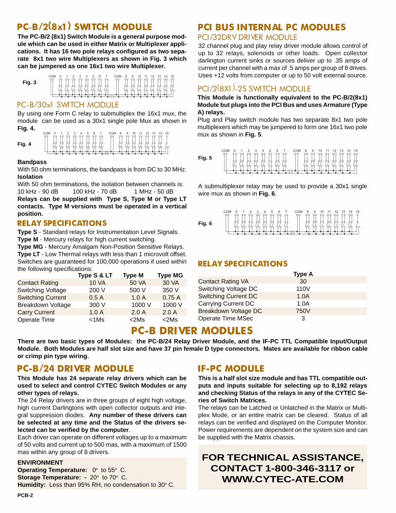
BandpassWith 50 ohm terminations, the bandpass is from DC to 30 MHz.IsolationWith 50 ohm terminations, the isolation between channels is:10 kHz - 90 dB 100 kHz - 70 dB 1 MHz - 50 dBRelays can be supplied with Type S, Type M or Type LTcontacts. Type M versions must be operated in a verticalposition.
PC-B/2(8x1) SWITCH MODULEThe PC-B/2 (8x1) Switch Module is a general purpose mod-ule which can be used in either Matrix or Multiplexer appli-cations. It has 16 two pole relays configured as two sepa-rate 8x1 two wire Multiplexers as shown in Fig. 3 whichcan be jumpered as one 16x1 two wire Multiplexer.
By using one Form C relay to submultiplex the 16x1 mux, themodule can be used as a 30x1 single pole Mux as shown inFig. 4.
Type S - Standard relays for Instrumentation Level Signals.Type M - Mercury relays for high current switching.Type MG - Mercury Amalgam Non-Position Sensitive Relays.Type LT - Low Thermal relays with less than 1 microvolt offset.Switches are guaranteed for 100,000 operations if used withinthe following specifications:
There are two basic types of Modules: the PC-B/24 Relay Driver Module, and the IF-PC TTL Compatible Input/OutputModule. Both Modules are half slot size and have 37 pin female D type connectors. Mates are available for ribbon cableor crimp pin type wiring.
Fig. 3
Fig. 4
Fig. 5
Fig. 6RELAY SPECIFICATIONS
PC-B DRIVER MODULES
PC-B/24 DRIVER MODULEThis Module has 24 separate relay drivers which can beused to select and control CYTEC Switch Modules or anyother types of relays.The 24 Relay drivers are in three groups of eight high voltage,high current Darlingtons with open collector outputs and inte-gral suppression diodes. Any number of these drivers canbe selected at any time and the Status of the drivers se-lected can be verified by the computer .Each driver can operate on different voltages up to a maximumof 50 volts and current up to 500 mas, with a maximum of 1500mas within any group of 8 drivers.
This is a half slot size module and has TTL compatible out-puts and inputs suitable for selecting up to 8,192 relaysand checking Status of the relays in any of the CYTEC Se-ries of Switch Matrices.The relays can be Latched or Unlatched in the Matrix or Multi-plex Mode, or an entire matrix can be cleared. Status of allrelays can be verified and displayed on the Computer Monitor.Power requirements are dependent on the system size and canbe supplied with the Matrix chassis.
IF-PC MODULE
0 1 2 3 4 5 6 7 8 9 10 11 12 13 14 15COM COM
0 1 2 3 4 5 6 7 8 9 10 11 12 13 14 15COM COM
FOR TECHNICAL ASSISTANCE,CONTACT 1-800-346-3117 or
WWW.CYTEC-ATE.COM
ENVIRONMENTOperating Temperature: 0o to 55o C.Storage Temperature: - 20o to 70o C.Humidity: Less than 95% RH, no condensation to 30o C.
PC-B/30x1 SWITCH MODULE
PCB-2
Type S & LT Type M Type MGContact Rating 10 VA 50 VA 30 VASwitching Voltage 200 V 500 V 350 VSwitching Current 0.5 A 1.0 A 0.75 ABreakdown Voltage 300 V 1000 V 1000 VCarry Current 1.0 A 2.0 A 2.0 AOperate Time <1Ms <2Ms <2Ms
PCI BUS INTERNAL PC MODULESPCI/32DRV DRIVER MODULE32 channel plug and play relay driver module allows control ofup to 32 relays, solenoids or other loads. Open collectordarlington current sinks or sources deliver up to .35 amps ofcurrent per channel with a max of .5 amps per group of 8 drives.Uses +12 volts from computer or up to 50 volt external source.
PCI/2(8X1)-2S SWITCH MODULE
0 1 2 3 4 5 6 7 8 9 10 11 12 13 14 15COM COM
Plug and Play switch module has two separate 8x1 two polemultiplexers which may be jumpered to form one 16x1 two polemux as shown in Fig. 5 .
A submultiplexer relay may be used to provide a 30x1 singlewire mux as shown in Fig. 6 .
0 1 2 3 4 5 6 7 8 9 10 11 12 13 14 15COM COM
RELAY SPECIFICATIONSType A
Contact Rating VA 30Switching Voltage DC 110VSwitching Current DC 1.0ACarrying Current DC 1.0ABreakdown Voltage DC 750VOperate Time MSec 3
This Module is functionally equivalent to the PC-B/2(8x1)Module but plugs into the PCI Bus and uses Armature (TypeA) relays.

2555 Baird Road, Penfield, New York 14526 (585) 381-4740 Fax (585) 381-0475
SWITCH MATRIX UNITS
MAINFRAMES
PX-1
PX/512 SWITCH MATRIXThe PX/512 Series of Switching Matrices are compact and economically priced units using highreliability Reed Relay Modules assembled into pre-wired Mainframes or Expansion Chassis toassemble a 32x16 Matrix, two 32x8 Matrices or a 64x8 Matrix with either single or two pole signalswitching. Computer Control can be from IEEE488 BUS, RS232 Serial or 10Base-T LAN.
SPECIAL FEATURES:• Matrix layout for high bandpass of 20 MHz and crosstalk
less than -40 dB at 10 MHz.
• Status Feedback to the computer from the relay coil drive
gives positive assurance that selected relay is energized.
• Interrogation Mode gives readout of all switched paths in
terms of inputs and outputs connected.
The units are all 19" rack mounted Chassis, 3.5" high, pre-wired to accept up to 16 of the PX/32 SwitchModules and a Control Module. Signal inputs and outputs are available with either coaxial BNC recep-tacles (-N), Header type connectors (-H) or screw terminals (-S).
These are stand alone pre-wired chassis with low noisepower supplies and motherboards to accept 16 Switch Mod-ules and a Control Module.There are two basic series of Mainframes:
PX/512-1 MAINFRAMESThese are 16" deep chassis pre-wired for single pole switch-ing matrices.PX/512-1A has a pre-wired motherboard accepting 16 of thePX/2x16-1 Switch Modules in a 32x16 Switch matrix configura-tion.PX/512-1B has a pre-wired motherboard accepting 16 of thePX/2(2x8)-1 Switch Modules in two separate 32x8 matriceswhich can be combined as one 64x8 matrix.
PX/512-2 MAINFRAMESThese are 21" deep chassis pre-wired for two pole switchingmatrices.PX/512-2A has pre-wired motherboards accepting 16 of the PX/2x16-2 Switch Modules in a 32x16 matrix configuration.PX/512-2B has pre-wired motherboards accepting 16 of the PX/2(2x8)-2 Switch Modules in two separate 32x8 matrices whichcan be combined as one 64x8 matrix.
EXPANSION CHASSISThese units are pre-wired to accept 16 Switch Modulesand an Expansion Interface Module so that several chas-sis can be controlled and receive power from one MESAControl Unit as shown in the MESA Bulletin.These Expansion Chassis are available in the same matrixconfigurations as the Mainframes.
PX/512-E-1 EXPANSION CHASSISThese are 16" deep chassis accepting single pole switch mod-ules.PX/512-E-1A has a 32x16 matrix configuration.PX/512-E-1B has two 32x8 matrices which can be combinedas one 64x8 matrix.
PX/512-E-2 EXPANSION CHASSISThese are 21" deep chassis accepting two pole switch mod-ules.PX/512-E-2A has a 32x16 matrix configuration.PX/512-E-2B has two 32x8 matrices which can be combinedas one 64x8 matrix.
CUSTOM CHASSISThe Mainframes and Expansion Chassis can be supplied wiredout to customer specified connectors or in special configura-tions.
• Optional Manual Control with visual display of selected switch path.
• Optional nonvolatile Ram for storage of preset or power-up configuration.
• VMCS Virtual Manual Control Software for Remote operation using a full
Graphical User Interface .
BULLETINPX-6
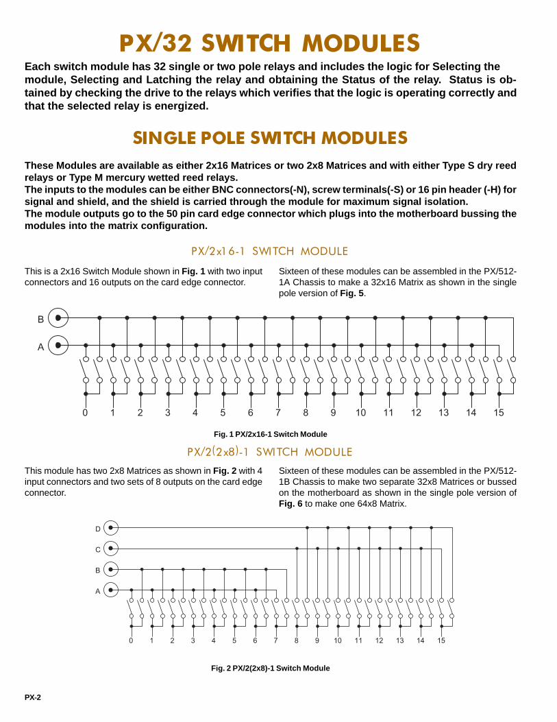
PX/32 SWITCH MODULESEach switch module has 32 single or two pole relays and includes the logic for Selecting themodule, Selecting and Latching the relay and obtaining the Status of the relay. Status is ob-tained by checking the drive to the relays which verifies that the logic is operating correctly andthat the selected relay is energized.
SINGLE POLE SWITCH MODULESThese Modules are available as either 2x16 Matrices or two 2x8 Matrices and with either Type S dry reedrelays or Type M mercury wetted reed relays.The inputs to the modules can be either BNC connectors(-N), screw terminals(-S) or 16 pin header (-H) forsignal and shield, and the shield is carried through the module for maximum signal isolation.The module outputs go to the 50 pin card edge connector which plugs into the motherboard bussing themodules into the matrix configuration.
PX/2x16-1 SWITCH MODULE
This is a 2x16 Switch Module shown in Fig. 1 with two inputconnectors and 16 outputs on the card edge connector.
Sixteen of these modules can be assembled in the PX/512-1A Chassis to make a 32x16 Matrix as shown in the singlepole version of Fig. 5 .
Fig. 1 PX/2x16-1 Switch Module
Fig. 2 PX/2(2x8)-1 Switch Module
PX/2(2x8)-1 SWITCH MODULE
This module has two 2x8 Matrices as shown in Fig. 2 with 4input connectors and two sets of 8 outputs on the card edgeconnector.
Sixteen of these modules can be assembled in the PX/512-1B Chassis to make two separate 32x8 Matrices or bussedon the motherboard as shown in the single pole version ofFig. 6 to make one 64x8 Matrix.
PX-2
0 1 2 3 4 5 6 7 8 9 10 11 12 13 14 15
A
B
0 1 2 3 4 5 6 7 8 9 10 11 12 13 14 15
A
B
C
D
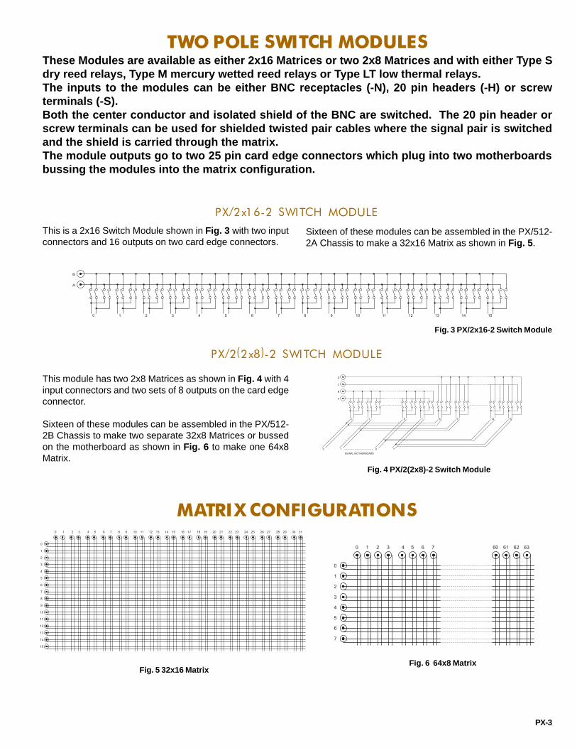
PX-3
TWO POLE SWITCH MODULESThese Modules are available as either 2x16 Matrices or two 2x8 Matrices and with either Type Sdry reed relays, Type M mercury wetted reed relays or Type LT low thermal relays.The inputs to the modules can be either BNC receptacles (-N), 20 pin headers (-H) or screwterminals (-S).Both the center conductor and isolated shield of the BNC are switched. The 20 pin header orscrew terminals can be used for shielded twisted pair cables where the signal pair is switchedand the shield is carried through the matrix.The module outputs go to two 25 pin card edge connectors which plug into two motherboardsbussing the modules into the matrix configuration.
PX/2x16-2 SWITCH MODULE
This is a 2x16 Switch Module shown in Fig. 3 with two inputconnectors and 16 outputs on two card edge connectors.
Sixteen of these modules can be assembled in the PX/512-2A Chassis to make a 32x16 Matrix as shown in Fig. 5 .
Fig. 3 PX/2x16-2 Switch Module
Fig. 4 PX/2(2x8)-2 Switch Module
PX/2(2x8)-2 SWITCH MODULE
This module has two 2x8 Matrices as shown in Fig. 4 with 4input connectors and two sets of 8 outputs on the card edgeconnector.
Sixteen of these modules can be assembled in the PX/512-2B Chassis to make two separate 32x8 Matrices or bussedon the motherboard as shown in Fig. 6 to make one 64x8Matrix.
MATRIX CONFIGURATIONS
Fig. 5 32x16 MatrixFig. 6 64x8 Matrix
0 1 2 3 4 5 6 7 8 9 10 11 12 13 14 15
A
B
0 1 6 7 8 9 14 15
A
B
C
D
0 1 6 7
SIGNAL MOTHERBOARD
0 1 2 3 4 5 6 7 8 9 10 11 12 13 14 15 16 17 18 19 20 21 22 23 24 25 26 27 28 29 30 31
0
1
2
3
4
5
6
7
8
9
10
11
12
13
14
15
0 1 2 3 4 5 6 7 60 61 62 63
0
1
2
3
4
5
6
7
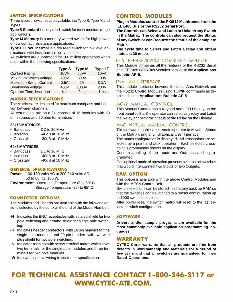
RAM OPTION
PX-4
CONTROL MODULES
FOR TECHNICAL ASSISTANCE CONTACT 1-800-346-3117 orWWW.CYTEC-ATE.COM.
SWITCH SPECIFICATIONS
The Modules and Chassis are available with the following op-tions selected by the suffix at the end of the Model Number:
CONNECTOR OPTIONS
Power - 100-130 Volts AC or 200-240 Volts AC,50 to 60 Hz, 100 W.
Environment - Operating Temperature 00 to 500 C.Storage Temperature -250 to 650 C.
GENERAL SPECIFICATIONS
• Bandpass DC to 10 MHz• Isolation -40dB at 10 MHz• Crosstalk -40dB at 10 MHz
64x8 MATRICES
• Bandpass DC to 20 MHz• Isolation -40dB at 10 MHz• Crosstalk -30dB at 10 MHz
32x16 MATRICES
The Matrices are designed for maximum bandpass and isola-tion between channels.All test results are on a full chassis of 16 modules with 50ohm source and 50 ohm termination.
MATRIX SPECIFICATIONS
Three types of switches are available, the Type S, Type M andType LT.Type S Standard is a dry reed switch for most medium rangeapplications.Type M Mercury is a mercury wetted switch for high poweror low contact resistance applications.Type LT Low Thermal is a dry reed switch for low level ap-plications with less than 1 microvolt offset.All switches are guaranteed for 100 million operations whenused within the following specifications:
SOFTWARE
This option is available with the above Control Modules andwith the MESA Control Unit.Switch selections can be stored in a battery back up RAM sothat the switches can be latched to a preset configuration upto 1000 switch selections.After power loss, the switch matrix will reset to the last se-lected switch configuration.
This Manual Control has a Keypad and LCD Display on thefront panel so that the operator can select any relay and Latchthe Relay or check the Status of the Relay on the Display.
MC-2 MANUAL CONTROL
This Module combines all the features of the RS232 Serialand IEEE488 GPIB Bus Modules detailed in the ApplicationsBulletin AP-5 .
IF-5 IEEE488/RS232 COMBINED MODULE
Plug in Modules control the PX/512 Mainframes from theIEEE488 Bus or the RS232 Serial Port.The Controls can Select and Latch or Unlatch any Switchin the Matrix. The controls can also request the Statusof any Switch or can Request the Status of the completeMatrix.The cycle time to Select and Latch a relay and obtainstatus is 30 msec.
IF-6 LAN INTERFACE
Drivers and/or sample programs are available for themost commonly available application programming lan-guages.
VMC VIRTUAL MANUAL CONTROLThis software enables the remote operator to view the Statusof the Matrix using a full Graphical User Interface.The matrix configuration is displayed and crosspoints are se-lected by a point and click operation. Each selected cross-point is prominently shown on the display.Custom labelling of the Inputs and Outputs can be pro-grammed.One optional mode of operation prevents selection of switchesthat would interconnect two Inputs or two Outputs.
This module interfaces between the Local Area Network andthe RS232 Control Modules using TCP/IP commands as de-scribed in the Applications Bulletin AP-5 .
Type S Type M Type LTContact Rating 10VA 50VA 10VAMaximum Switch Voltage 200V 500V 100VMaximum Switch Current 0.5A 2A 0.2ABreakdown Voltage 400V 1000V 200VOperate Time, less than 1ms 2ms 1ms
-N
-H
-S
-W
Indicates the BNC receptacles with isolated shield for twopole switching and ground shield for single pole switch-ing.Indicates header connectors, with 16 pin headers for thesingle pole modules and 20 pin headers with two wireplus shield for two pole switching.Indicates terminal with screw terminal mates which havetwo terminals for the single pole modules and three ter-minals for two pole modules.Indicates special wiring to customer specification.
WARRANTYCYTEC Corp. warrants that all products are free fromdefects in Workmanship and Materials for a period offive years and that all switches are guaranteed for theirRated Operations.

2555 Baird Road, Penfield, New York 14526 (585) 381-4740 FAX (585) 381-0475
RJ SERIESSWITCHING SYSTEMS
FOR COMMUNICATIONS AND AUTOMATED TEST
RJV/48 MainframeRJM/128 Mainframe
BULLETINRJ-4
The RJ Series of Computer Controlled Switching Systems are engineered for both analog anddigital communication applications. A modular design is used, and interchangeable ControlModules, Switch Modules and Display Modules plug into prewired chassis. This allows systemsto be tailored to fit specific applications. Connectors are either RJ12 or RJ45, and up to 8 wirescan be switched. Switchpoint Status Feedback is standard, and LED switch point Status Displayis included with most models. Control options include: IEEE488 Bus (GPIB), RS232, 10Base-TEthernet LAN and Universal Serial Bus (USB). Manual Controls such as the Palm PC ComputingPlatform are optionally available.The units are available as either Mainframes with dedicated Control Modules and power sup-plies or as Expansion Chassis that are controlled and powered via a MESA Control Chassis.
RJA and RJM MATRICES - FEATURES
RJX MULTIPLEXERS/MATRICESLow cost, high reliability units using reed relays.Suitable for analog voice and digital communications.RJ12 Telco connectors.Apps. include: Modems, ISDN, Serial Data, DSL, T1/E1.2, 4, or 6 wires switched.Optional Type M Mercury Relays with 2 or 4 wire apps., ca-pable of switching up to 500 volts, 2 amps or 50 wattsBandpass is 25 MHz (-3dB) with Crosstalk -60dB @ 5 MHz.
RJM MATRICESHigh performance systems designed for high speed digitaldata communications signals.CAT5 RJ45 connectors.Applications include: 10/100Base-T, T1, ISDN, DSL, ADSL.4 or 8 wires switched using sensitive Type A relays.Capable of switching up to 150 volts and 1 amp.Bandpass is 30 MHz @ -3dB, Crosstalk is -60dB @ 20 MHz.
Low cost, bidirectional four-wire Solid State Matrices.Applications include: 10Base-T, TTL, Token Ring, 0 to 5 voltanalog signals.Standard matrix configurations are 8x8, 8x16 and 16x16.RJ45, D9 or IDC header connectors.Bandpass (-3dB) is 50 MHz at 50 ohms impedance.Crosstalk is -40dB @ 20MHz.
Low cost, high reliability bidirectional systems.Applications include: 10Base-T, Token Ring, ISDN.4 or 8 wire Type S Reed Relay switch modules with RJ45s.Multiplexers from 1x8 to 1x128. Matrices from 2x4 to2x64.Full LED front panel Display and Status Feedback.Bandpass is 20 MHz at -3dB, Crosstalk is -60dB @ 5 MHz.
RJV MULTIPLEXERS/MATRICESHigh performance passive systems designed for high speeddata communications.Apps. include: 10Base-T/100Base-T/Gigabit Ethernet, ATM.4 or 8 wire Type A Switch Modules, CAT5 RJ45 connectors.Low Crosstalk, exceptional Longitudinal Balance, Low In-sertion Loss.Bidirectional multiplexers from 1x12 to 1x144.Bidirectional matrices from 2x6 to 4x72.CAT5 compliant.Full Status Feedback.
Passive, bidirectional systems.Modularized design permits incremental expansion.Single chassis configurations from 2x4 to 16x8 (or 32x4).Larger systems built utilizing MESA Control Chassis and upto 16 Expansion Chassis.Full LED switchpoint Display with Status Feedback.
RJA MATRICES
RJB MATRICES
WARRANTYAll CYTEC products are warranted against defects inworkmanship and materials for a period of five years.
••••
•
••••••
•
•
•••••
••
••••
••••
••
•
•••
••••
RJ-1
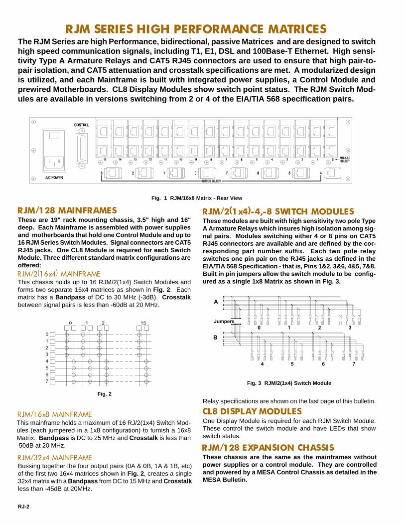
CL8 DISPLAY MODULES
RJM SERIES HIGH PERFORMANCE MATRICES
These are 19" rack mounting chassis, 3.5" high and 16"deep. Each Mainframe is assembled with power suppliesand motherboards that hold one Control Module and up to16 RJM Series Switch Modules. Signal connectors are CAT5RJ45 jacks. One CL8 Module is required for each SwitchModule. Three different standard matrix configurations areoffered:RJM/2(16x4) MAINFRAMEThis chassis holds up to 16 RJM/2(1x4) Switch Modules andforms two separate 16x4 matrices as shown in Fig. 2 . Eachmatrix has a Bandpass of DC to 30 MHz (-3dB). Crosstalkbetween signal pairs is less than -60dB at 20 MHz.
RJM/16x8 MAINFRAMEThis mainframe holds a maximum of 16 RJ/2(1x4) Switch Mod-ules (each jumpered in a 1x8 configuration) to furnish a 16x8Matrix. Bandpass is DC to 25 MHz and Crosstalk is less than-50dB at 20 MHz.
RJM/32x4 MAINFRAME
RJM/2(1x4)-4,-8 SWITCH MODULESThese modules are built with high sensitivity two pole TypeA Armature Relays which insures high isolation among sig-nal pairs. Modules switching either 4 or 8 pins on CAT5RJ45 connectors are available and are defined by the cor-responding part number suffix. Each two pole relayswitches one pin pair on the RJ45 jacks as defined in theEIA/TIA 568 Specification - that is, Pins 1&2, 3&6, 4&5, 7&8.Built in pin jumpers allow the switch module to be config-ured as a single 1x8 Matrix as shown in Fig. 3.
One Display Module is required for each RJM Switch Module.These control the switch module and have LEDs that showswitch status.
The RJM Series are high Performance, bidirectional, passive Matrices and are designed to switchhigh speed communication signals, including T1, E1, DSL and 100Base-T Ethernet. High sensi-tivity Type A Armature Relays and CAT5 RJ45 connectors are used to ensure that high pair-to-pair isolation, and CAT5 attenuation and crosstalk specifications are met. A modularized designis utilized, and each Mainframe is built with integrated power supplies, a Control Module andprewired Motherboards. CL8 Display Modules show switch point status. The RJM Switch Mod-ules are available in versions switching from 2 or 4 of the EIA/TIA 568 specification pairs.
Fig. 2
A
B
Jumpers0 1 2 3
4 5 6 7
Fig. 3 RJM/2(1x4) Switch Module
0 1 2 15
4567
0123
Fig. 1 RJM/16x8 Matrix - Rear View
Relay specifications are shown on the last page of this bulletin.
RJM/128 MAINFRAMES
RJM/128 EXPANSION CHASSISThese chassis are the same as the mainframes withoutpower supplies or a control module. They are controlledand powered by a MESA Control Chassis as detailed in theMESA Bulletin.
Bussing together the four output pairs (0A & 0B, 1A & 1B, etc)of the first two 16x4 matrices shown in Fig. 2 , creates a single32x4 matrix with a Bandpass from DC to 15 MHz and Crosstalkless than -45dB at 20MHz.
RJ-2

The RJV Series are high performance, bidirectional, passive Multiplexers or Matrices designedfor demanding communication applications such as 100Base-T Network Switching. These unitsare built with high sensitivity Type A Armature Relays to insure low signal-to-signal crosstalk.Exceptional longitudinal balance and low insertion losses are achieved at high data rates. Con-nectors are CAT5 RJ45. A modularized design is used, and each Mainframe is built with inte-grated power supplies, a Control Module and a motherboard that holds the RJV Switch Modules.This results in a great deal of configuration flexibility.
0 1 2 3 4 5 6 7 8 9 10 11
0
Backplane Connection
RJV/48 MAINFRAMEThis chassis is 5.25" high and accepts up to four RJV SeriesSwitch Modules. The modules can be used individually, or theycan be bussed together in several different configurations. Asa 48x1 Mux, Bandpass is 100 MHz at -2dB and Near EndCrosstalk between wire pairs (NEXT) is -42dB at 80 MHz, whichexceeds 100Base-TX network specifications.
Fig. 5
RJV/144 MAINFRAMEThis is a 19" rack mounting chassis, 10.5" high and 16" deepand is designed to hold up to twelve RJV Series Switch Mod-ules. These can be used individually or bussed together inseveral configurations. In all configurations, 100Base-TX Band-pass and NEXT specifications are met.
RJV/12x1-4, -8 SWITCH MODULEEach module supplies a 12x1 Multiplexer as shown in Fig. 5 .Four or 8 pole versions are available. Four modules can beplaced in the RJV/48 chassis to supply four (12x1), two (24x1),or one (48x1) Mux. In the RJV/144 chassis, one (144x1), two(72x1), four (36x1), or twelve (12x1) Muxes can be configuredusing 12 switch modules.
RJV/6x2-4 SWITCH MODULEThese modules switch four poles in a 6x2 Matrix configurationas shown in Fig. 6 . They can be assembled in the RJV/48 asone (24x2), two (12x2) or four (6x2) Matrices. In the RJV/144 ,one (72x2), two (36x2), four (18x2) or twelve (6x2) Matricescan be achieved.RJV/6x4-4 SWITCH MODULEThese also switch four poles but are configured as a 6x4 Matrixas shown in Fig. 7 . They can be assembled in the RJV/48 tocreate one (24x4), two (12x4) or four (6x4) Matrices, and in theRJV/144 to make one (72x4), two (36x4), four (18x4) or twelve(6x4) Matrices.
The RJV Switch Modules can be assembled in many differ-ent ways to provide a number of additional configurations.Contact our Applications Engineers to discuss your spe-cific needs.
0 1 2 3 4 5
0
1
Backplane Connections
0 1 2 3 4 5
0
1
2
3
BackplaneConnections
Fig. 6 Fig. 7
RJV SERIES MULTIPLEXERS and MATRICES
Fig. 4 RJV/144 Mainframe - Rear View
RJV/4(1x2)-4, -8 SWITCH MODULEEach module furnishes four individual 1x2 or "A/B" switches.Four and 8 pole versions are available. Form C relays are used,meaning each of the four switches has a Normally Closed posi-tion. In an RJV/48, four modules will furnish 16 A/B Switches,and in the RJV/144, 12 modules will give 48 switches.
Four Pole Versions of Switch Modules are shown
RJV/144-E EXPANSION CHASSISThis is the same as above but is powered and controlled viaa MESA Control Chassis as detailed in the MESA Bulletin.
RJ-3
All RJV Switch Modules use high sensitivity, high isolation Type A Armature Relays and CAT5 RJ45connectors. Up to eight poles can be switched (but not on all models). Signals can be routed to theCommon connectors on the individual modules or alternately to the motherboard bus. The latter inter-connects the modules and provides larger multiplexers and matrices.
RJV SWITCH MODULES

The RJB Series are bidirectional, nonblocking, four wire Solid State Matrices and are used toswitch the following signal types: TTL level analog or digital (0-5 volts), 10Base-T or TokenRing. Each Mainframe is built with integrated power supplies, a Control Module, either an 8x8 or16x16 Solid State Switch Module and one of three types of built in Interface Modules. TheInterface Modules adapt the solid state switch fabric to the signals that are to be switched.
RJB/8x8 and RJB/16x16 MAINFRAMESThese are 19" rack mounting units, either 1.75" or3.5" high. (Fig. 8 shows the 1.75" chassis.) Eachchassis is built with the RJB/8x8 or RJB/16x16 SolidState Switch Module, one Control Module, powersupplies and the appropriate Interface Modules.Standard connectors are: IDC headers for TTL,CAT5 RJ45s for Ethernet and 9 Pin D subminiaturesfor Token Ring. Other optional connectors can bespecified by the user. Please contact our Applica-tions Engineers for additional details.
RJB SOLID STATE SWITCH MODULESThe solid state switch fabric is the heart of the matrixand two standard models are offered: the RJB/8x8 andthe RJB/16x16. These furnish nonblocking, bidirectionalfour pole analog switching of 0 to +5 volts signals with alow path ON resistance of approximately 3 ohms. Band-pass (-3dB) is DC to 50 MHz at balanced relay andCrosstalk is -40dB at 20 MHz.
RJB/8x8 SWITCH MODULEThis is an 8x8 four wire solid state matrix. Any one of eightindividual four wire inputs can be connected to one of eightfour wire outputs. Signal inputs and outputs are wired fromtwo 34 pin IDC header connectors located on the Switch Mod-ule to the integrated Interface Modules, which also providethe rear panel connectors.RJB/16x16 SWITCH MODULEThis is a 16x16 four wire bidirectional matrix. Any one of 16separate four wire inputs can be switched to any one of 16individual four wire outputs. Signal inputs and outputs arewired out from four 34 pin header connectors located on theSwitch Module to the required Interface Modules. The Inter-face Modules furnish the rear panel signal connectors.
RJB INTERFACE MODULESThe core RJB Solid State Switch Fabric handles TTLlevel signals of 0 to +5 volts. The RJB InterfaceModules are an interface between the core SwitchFabric and the input and output signals that are tobe switched. These Interface Modules enable thematrix to handle 10Base-T and Token Ring signals.Each Interface accepts eight input or output sig-nals, therefore, two are required in the RJB/8x8 Ma-trix and four are needed in the RJB/16x16.
RJB/M1 INTERFACEThis is used whenever TTL level signals are being switched.The RJB/M1 essentially provides a hard wired connectionbetween the RJB/8x8 or RJB/16x16 Solid State Switch Mod-ule and 34 pin header connectors on the chassis rear panel,with no signal transformation. Analog Pulse rates of 50 MHzcan be handled by this interface with low crosstalk betweensignal paths.
RJB/M2 INTERFACEThis adapts the unit to 10Base-T Ethernet LANs. This inter-face is built with CAT5 RJ45 rear panel connectors and iso-lation transformers as required by Ethernet. Bandpass andCrosstalk meet all 10Base-T Specifications.
RJB/M3 INTERFACEThis is used when Token Ring is to be switched. The mod-ules supply D9 connectors and transformers as required byToken Ring Networks. The D9 connector size increases thechassis height to 3.5".
OPTIONSCustom Interface Modules can be supplied for switch-ing other signal types. Please consult our ApplicationsEngineers.
RJB SERIES SOLID STATE SWITCH MATRICES
Fig. 8 RJB/16x16 Matrix with RJB/M2 Ethernet Adaptor Option
RJ-4

The RJA Series are low cost, high reliability, passive Matrices that are designed for analog voiceand digital communication applications. Two, four or six pins on RJ12 Jacks are switched usingreed relays. Each mainframe holds power supplies, a Control Module, up to 16 Switch Modulesand CL8 Display Modules. CL8 Modules control the switch module and show switch status.
RJA SERIES HIGH RELIABILITY MATRICES
RJA/128 MAINFRAMES
This unit furnishes two independent 16x4 matrices when filledwith 16 RJ/2(1x4) Switch Modules as shown in Fig. 1 on thesecond page of this bulletin. Bandpass is DC to 30 MHz, andCrosstalk is less than -60dB at 5 MHz.RJA/16x8 MAINFRAMEThis chassis holds 16 RJ/2(1x4) Switch Modules jumpered as1x8s to form a 16x8 Matrix. Bandpass is DC to 25 MHz withCrosstalk less than -60dB at 1 MHz.
Bussing together the four output pairs (0A & 0B, 1A & 1B, etc.)of the two 16x4 matrices shown in Fig. 2 on the second page ofthis bulletin creates a single 32x4 matrix with a Bandpass fromDC to 20 MHz and Crosstalk less than -60dB at 1 MHz.
RJ SWITCH MODULESEach RJ Series Switch Module is built with eight Type SStandard or Type M Mercury Reed Relays and two RJ12Jacks. Either 2, 4 or 6 poles are switched. Each moduleprovides two 1x4 matrices as shown in Fig. 9, with optionaljumpers creating a 1x8 configuration.RJ/2(1x4)-2 SWITCH MODULEEight 2 pole relays switch the inner pins on the RJ12 connec-tors, and the outer four pins are wired as shields.
Similar to the above, this is built with 4 pole relays. The RJ12'sinner four pins carry signals while the outer two are shields.RJ/2(1x4)-6 SWITCH MODULE
Fig. 9
0 1 2 3 4 5 6 7
A
B
RJ/2(1x4)-4 SWITCH MODULE
RJX SERIES HIGH RELIABILITY MULTIPLEXERS
RJX/8x1-ISO SWITCH MODULES
This module has eight, 4 or 8 pole Type S Reed Relays ar-ranged in a 4x2 configuration. The Bandpass at -1dB is 80MHz and Crosstalk is -40dB at 10 MHz.
RJX/32 MAINFRAMEThis unit is 3.5" high and accepts up to four RJX Switch Mod-ules. It can be configured as either a 32x1 Multiplexer or 16x2Matrix. Bandpass as a 32x1 Multiplexer is -3dB at 35 MHz,and Crosstalk is -40dB at 10 MHz.
RJX/128 MAINFRAMEThis unit is 8.75" high and accepts up to 16 RJX Switch Mod-ules and 16 Display Modules. Many different configurationsare possible, ranging from sixteen individual 1x8 multiplexersup to either a 128x1 multiplexer or a 64x2 matrix. Bandpassas a 128x1 mux is DC to 15 MHz at -3dB and Crosstalk is -30dB at 10 MHz.
This module has eight, 4 or 8 pole Type S Standard Dry ReedRelays arranged as an 8x1 multiplexer as shown in Fig. 10 .Bandpass is 80 MHz at -1dB and Crosstalk is -40dB at 10MHz.
One CL8 Display Module is required for each Switch Moduleonly in the RJX/128 Mainframe .
RJX/4x2-ISO SWITCH MODULES
These are 19" rack mounting chassis, 3.5" high and 12"deep. Signal connectors are RJ12 Telco Jacks. Three dif-ferent matrices are offered.
RJA/32x4 MAINFRAME This uses 6 pole relays and switches all pins on the RJ12s. It isnot available with Type M relays.
CL8 DISPLAY MODULES
0 1 2 3
4 5 6 7
COM
BACKPLANE
Fig. 10
One Display Module is required for each RJA Switch Module.
CL8 DISPLAY MODULES
RJA/128 EXPANSION CHASSISThese chassis are the same as above but are powered andcontrolled via a MESA Control Chassis as detailed in theMESA Bulletin.
RJA/2(16x4) MAINFRAME
The RJX Series are low cost, passive Multiplexers. These systems are designed to switch communica-tions signals such as analog voice and 10Base-T Ethernet. Signal connectors are RJ45 Jacks, and bothfour and eight pole modules are available. The four wire versions switch Pins, 1, 2, 3 and 6 of the RJ45s.Each Mainframe is built with power supplies, a Control Module and prewired motherboards that hold theRJX Switch Modules. A full LED Display is included.
RJ-5

CONTROLS
RJA, RJM, RJX/128 CONTROL MODULESIF-1 PARALLEL PORT
IF-3 RS232 SERIAL
IF-4 IEEE488 BUS TALK/LISTEN
IF-5 IEEE488/RS232
M/128 MANUAL CONTROLS
RJX/32 MAINFRAME CONTROLSIF-3B RS232 SERIAL
IF-4B IEEE488 BUS TALK/LISTEN
M/32 MANUAL CONTROLS
RJV AND RJB SERIES CONTROLSIF-3C RS232 SERIAL
IF-4C IEEE488 GPIB
CONTACT 1-800-346-3117or WWW.CYTEC-ATE.COM FOR TECHNICAL ASSISTANCE
MC/2 MANUAL CONTROL - RJV ONLY
SWITCH SPECIFICATIONS
SPECIFICATION TYPE S TYPE M TYPE AContact Rating VA 10 50 30Switching Voltage DC 200V 500V 110VSwitching Current DC .5A 1.0A 1.0 ACarrying Current DC 1.0A 2.0A 1.0ABreakdown Voltage DC 400V 1000V 750VOperate Time msec 1 2 3
IF-7B COMBINED USB/RS232
IF-7C COMBINED USB/RS232
IF-7 COMBINED USB/RS232
This requires 14 individual binary, TTL level lines from the con-trolling computer. These select Switch and Mode, Strobe theselected command and return switch point Status.
This module has all the RS232 features detailed in Applica-tions Bulletin AP-5.
This module has all the IEEE488 BUS features detailed in Ap-plications Bulletin AP-5.
This module combines both the IEEE488 BUS and RS232 fea-tures detailed in Applications Bulletin AP-5.
This control module is plug-and-play compatible with UniversalSerial Bus and furnishes dual controls via both RS232 and USB,allowing users to switch to USB control as COM ports becomeobsolete on new computers.
Thumbwheels and switches on the front panel select and con-trol up to 128 relays.
This Control Module has all the RS232 features detailed in Ap-plications Bulletin AP-5.
This module has all the IEEE488 BUS features detailed in Ap-plications Bulletin AP-5.
Thumbwheels and switches on the front panel select and con-trol all relays.
This module has all the RS232 features detailed in Applica-tions Bulletin AP-5.
This module has all the IEEE488 BUS features detailed in Ap-plications Bulletin AP-5.IF-6 LAN INTERFACEThis module allows control via a Local Area Network using TCP/IP protocols detailed in the AP-5 Bulletin.
IF-6 LAN INTERFACEThis module allows control via a Local Area Network using TCP/IP protocols detailed in the AP-5 Bulletin.
This module allows control via a Local Area Network using TCP/IP protocols detailed in the AP-5 Bulletin.
IF-6 LAN INTERFACE
GENERAL SPECIFICATIONSWEIGHT - Weight is dependent on chassis type and the num-ber of modules. Please contact CYTEC for specific details.POWER - 100 watts at 100-130 Volts AC or 200-260 Volts AC.ENVIRONMENT - Operating 00 C to 500 C
Storage -250 C to 650 C
The RJM Matrices and RJV Multiplexers are built with highsensitivity Type A Armature relays. The RJB is a solid state(only) matrix. All other units are supplied with Type S Stan-dard Dry Reed Relays. The RJA Matrices can optionally bebuilt with Type M Mercury Wetted Reed Relays in the 2 and4 pole versions only.
This control module is plug-and-play compatible with UniversalSerial Bus and furnishes dual controls via both RS232 and USB,allowing users to switch to USB control as COM ports becomeobsolete on new computers.
This control module is plug-and-play compatible with UniversalSerial Bus and furnishes dual controls via both RS232 and USB,allowing users to switch to USB control as COM ports becomeobsolete on new computers.
PALM PC MANUAL CONTROLThis is currently available for use with the IF-4 IEEE488 ControlModule. Application Programs running on the Palm PC displaya virtual keypad manual control. It may be purchased with orwithout the Palm PC itself.
This Virtual Manual Control Software enables a remote opera-tor to view the Status of the Matrix and to Control Switch Selec-tion using a full Graphical User Interface.
VMCS
This Manual Control Option has a Keypad and LCD Display onthe front panel so that the operator can select any relay andverify that the relay has been selected via the display. It is onlyavailable for the RJV Series.
ADDITIONAL MANUAL CONTROL OPTIONSThe following Manual Control Options are available for ALLchassis mentioned in this Bulletin. Contact our TechnicalSales Representatives for more details and information.
The RJ Series Mainframes are computer controlled via: IEEE488 BUS, RS232 Serial, Ethernet LAN, Uni-versal Serial Bus (USB) or TTL Parallel Port. The Control Module selects any Mainframe switch point andis able to Latch, Unlatch and Request Status of the switch in both Matrix and Multiplex Modes.In the Matrix Mode, any number of switches can be closed at the same time. In the Multiplex Mode, onlyone switch can be closed at a time.
RJ-6
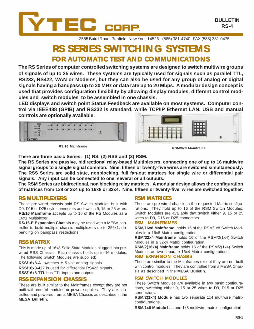
2555 Baird Road, Penfield, New York 14526 (585) 381-4740 FAX (585) 381-0475
RS SERIES SWITRS SERIES SWITRS SERIES SWITRS SERIES SWITRS SERIES SWITCHING SYSTEMSCHING SYSTEMSCHING SYSTEMSCHING SYSTEMSCHING SYSTEMSFOR AFOR AFOR AFOR AFOR AUTUTUTUTUTOMAOMAOMAOMAOMATIC TEST AND COMMUNICATIC TEST AND COMMUNICATIC TEST AND COMMUNICATIC TEST AND COMMUNICATIC TEST AND COMMUNICATIONSTIONSTIONSTIONSTIONS
RS/16 Mainframe RSM/8x8 Mainframe
The RS Series of computer controlled switching systems are designed to switch multiwire groupsof signals of up to 25 wires. These systems are typically used for signals such as parallel TTL,RS232, RS422, WAN or Modems, but they can also be used for any group of analog or digitalsignals having a bandpass up to 30 MHz or data rate up to 20 Mbps. A modular design concept isused that provides configuration flexibility by allowing display modules, different control mod-ules and switch modules to be assembled in one chassis.LED displays and switch point Status Feedback are available on most systems. Computer con-trol via IEEE488 (GPIB) and RS232 is standard, while TCP/IP Ethernet LAN, USB and manualcontrols are optionally available.
There are three basic Series: (1) RS, (2) RSS and (3) RSM.The RS Series are passive, bidirectional relay-based Multiplexers, connecting one of up to 16 multiwiresignal groups to a single signal common. Nine, fifteen or twenty-five wires are switched simultaneously.The RSS Series are solid state, nonblocking, full fan-out matrices for single wire or differential pairsignals. Any input can be connected to one, several or all outputs.The RSM Series are bidirectional, non blocking relay matrices. A modular design allows the configurationof matrices from 1x8 or 2x4 up to 16x8 or 32x4. Nine, fifteen or twenty-five wires are switched together.
RS MULRS MULRS MULRS MULRS MULTIPLEXERSTIPLEXERSTIPLEXERSTIPLEXERSTIPLEXERSThese pre-wired chassis hold RS Switch Modules built withD9, D15 or D25 style connectors and switch 9, 15 or 25 wires.RS/16 Mainframe accepts up to 16 of the RS Modules as a16x1 Multiplexer.RS/16-E Expansion Chassis may be used with a MESA con-troller to build multiple chassis multiplexers up to 256x1, de-pending on bandpass restrictions.
RSS MARSS MARSS MARSS MARSS MATRIXTRIXTRIXTRIXTRIXThis is made up of 16x8 Solid State Modules plugged into pre-wired RSS Chassis. Each chassis holds up to 16 modules.The following Switch Modules are supplied:RSS/16x8-A switches ± 5 volt analog signals.RSS/16x8-422 is used for differential RS422 signals.RSS/16x8-TTL has TTL inputs and outputs.
RSM MARSM MARSM MARSM MARSM MATRICESTRICESTRICESTRICESTRICESThese are pre-wired chassis in the requested Matrix configu-rations. They hold up to 16 of the RSM Switch Modules.Switch Modules are available that switch either 9, 15 or 25wires to D9, D15 or D25 connectors.
RSM SWITCH MODULESRSM SWITCH MODULESRSM SWITCH MODULESRSM SWITCH MODULESRSM SWITCH MODULESThese Switch Modules are available in two basic configura-tions, switching either 9, 15 or 25 wires to D9, D15 or D25connectors.RSM/2(1x4) Module has two separate 1x4 multiwire matrixconfigurations.RSM/1x8 Module has one 1x8 multiwire matrix configuration.
RSM MAINFRAMESRSM MAINFRAMESRSM MAINFRAMESRSM MAINFRAMESRSM MAINFRAMESRSM/16x8 Mainframe holds 16 of the RSM/1x8 Switch Mod-ules in a 16x8 Matrix configuration.RSM/32x4 Mainframe holds 16 of the RSM/2(1x4) SwitchModules in a 32x4 Matrix configuration.RSM/2(16x4) Mainframe holds 16 of the RSM/2(1x4) SwitchModules as two separate 16x4 Matrix configurations
BULLETINRS-4
RS-1
These are similar to the Mainframes except they are not builtwith control modules. They are controlled from a MESA Chas-sis as described in the MESA Bulletin.
RSM EXPRSM EXPRSM EXPRSM EXPRSM EXPANSION CHASSISANSION CHASSISANSION CHASSISANSION CHASSISANSION CHASSIS
RSS EXPRSS EXPRSS EXPRSS EXPRSS EXPANSION CHASSISANSION CHASSISANSION CHASSISANSION CHASSISANSION CHASSISThese are built similar to the Mainframes except they are notbuilt with control modules or power supplies. They are con-trolled and powered from a MESA Chassis as described in theMESA Bulletin.

RS/16 MAINFRAMERS/16 MAINFRAMERS/16 MAINFRAMERS/16 MAINFRAMERS/16 MAINFRAME
RS SWITRS SWITRS SWITRS SWITRS SWITCH MODULESCH MODULESCH MODULESCH MODULESCH MODULES
RSS/256 MAINFRAMERSS/256 MAINFRAMERSS/256 MAINFRAMERSS/256 MAINFRAMERSS/256 MAINFRAME
RSS/16x8 SOLID STRSS/16x8 SOLID STRSS/16x8 SOLID STRSS/16x8 SOLID STRSS/16x8 SOLID STAAAAATE MODULESTE MODULESTE MODULESTE MODULESTE MODULES
Fig. 2
RSS/16x8 TTL SWITRSS/16x8 TTL SWITRSS/16x8 TTL SWITRSS/16x8 TTL SWITRSS/16x8 TTL SWITCH MODULECH MODULECH MODULECH MODULECH MODULE
MAMAMAMAMATING CONNECTTING CONNECTTING CONNECTTING CONNECTTING CONNECTORSORSORSORSORS
RS MULRS MULRS MULRS MULRS MULTIPLEXERTIPLEXERTIPLEXERTIPLEXERTIPLEXERThese are passive, relay-based multiplexersswitching from 9 to 25 wire signals such as RS232,RS422 or TTL in applications including Modems,Printers or Token Ring.Their Bandpass is DC to 20 MHz.
These are 19" rack mounted units 3.5" high and 15.6" deepwith power supplies, LED Displays and pre-wired motherboardswhich accept the RS Switch Modules. This unit holds up tosixteen RS Switch Modules and has sixteen switchpoint sta-tus LEDs on the front panel. It can switch up to 25 wires fromsixteen input ports to one output port, or the reverse, as shownin Figure 1.
RSS MARSS MARSS MARSS MARSS MATRIXTRIXTRIXTRIXTRIXThese are built up from the RSS/16x8 Solid StateModules, which in turn are plugged into pre-wiredRSS chassis. Each module is an individual 16x8Matrix, and multiple modules can be intercon-nected to form larger matrix configurations.
The RS/9, RS/15 and RS/25 Modules are built with TypeA relays, switching 9, 15 and 25 poles. Connector typesare subminiature D9, D15 or D25, and either -P pins or -Ssockets can be user specified.RS/9 SWITCH MODULERS/9 SWITCH MODULERS/9 SWITCH MODULERS/9 SWITCH MODULERS/9 SWITCH MODULE
This is a solid state switch module and it is configuredas a 16 by 8 (16x8) matrix. Three separate versions arebuilt to handle either analog, TTL or RS422 signals. The16 inputs are wired to a 34 pin header, the 8 outputs to a20 pin header. The module is full fan out so any inputcan be connected to one, several or all outputs.
RSS/16x8-A SWITRSS/16x8-A SWITRSS/16x8-A SWITRSS/16x8-A SWITRSS/16x8-A SWITCH MODULECH MODULECH MODULECH MODULECH MODULE
RSS/16x8-422 SWITRSS/16x8-422 SWITRSS/16x8-422 SWITRSS/16x8-422 SWITRSS/16x8-422 SWITCH MODULECH MODULECH MODULECH MODULECH MODULESwitches sixteen individual, two wire RS422 signal inputs to8, two-wire RS422 outputs as shown in Fig. 2 at up to 10Mbps. Any input can be connected to one, several or even alloutputs.
This module switches +/-5 volt analog signals and has a typi-cal ON resistance of 60 ohms. Bandpass is 50 MHz whenterminated into 1K ohms. It can be used as a 16x8 or 8x16matrix.
This module switches TTL level signals and can be used aseither a 16x8 or 8x16 matrix. Any input can be connected toany or all outputs.
CUSTOM SWITCH MODULESCUSTOM SWITCH MODULESCUSTOM SWITCH MODULESCUSTOM SWITCH MODULESCUSTOM SWITCH MODULESSwitch Modules can be supplied that switch different types ofinput and output signals on the same module. For example,one module might have 16 two wire RS422 inputs switchedinto eight single wire TTL outputs.
J20-R - Twenty pin ribbon cable type header connectorJ20-C - Twenty pin crimp type header connectorJ34-R - Thirty-four pin ribbon cable type header connectorJ34-C - Thirty-four pin crimp type header connector
RS/15 SWITCH MODULERS/15 SWITCH MODULERS/15 SWITCH MODULERS/15 SWITCH MODULERS/15 SWITCH MODULEThis module has a D15 connector with Type A relays switch-ing all fifteen wires.RS/25 SWITCH MODULERS/25 SWITCH MODULERS/25 SWITCH MODULERS/25 SWITCH MODULERS/25 SWITCH MODULEThis module utilizes a D25 connector and Type A relays switch-ing all twenty-five wires.
AAAAAVVVVVAILABLE MAAILABLE MAAILABLE MAAILABLE MAAILABLE MATING CONNECTTING CONNECTTING CONNECTTING CONNECTTING CONNECTORSORSORSORSORS
D9-R - Nine pin ribbon cable connectorD9-C - Nine pin crimp type connectorD15-R - Fifteen pin ribbon cable connectorD15-C - Fifteen pin crimp type connectorD25-R - Twenty-five pin ribbon cable connectorD25-C - Twenty-five pin crimp type connector
������������ �������� ��� � � �� �����
���������
�� � �� �������
�������������
RS-2
This is a 19" rack mounted chassis, 5.25" high and 15.6"deep, pre-wired to accept the RSS Series of Switch Modules.The unit has one slot that holds the required control module,as well as slots for up to sixteen RSS/16x8 Switch Modules.Multiple switch modules can be combined to form larger ma-trices.
Figure 1
PLUG or SOCKET D TYPE CONNECTORSPLUG or SOCKET D TYPE CONNECTORSPLUG or SOCKET D TYPE CONNECTORSPLUG or SOCKET D TYPE CONNECTORSPLUG or SOCKET D TYPE CONNECTORSTo specify Plug (male) D type connectors, add -P to the SwitchModule part number. Adding -S specifies Socket (female)connectors. For example, the RS/15-S is built with a submin-iature D15 Socket connector.
This module is built with a D9 connector and Type A relaysand switches nine wires.
The following mating connectors can be purchased for a smalladditional charge.
EXPEXPEXPEXPEXPANSION CHASSISANSION CHASSISANSION CHASSISANSION CHASSISANSION CHASSISExpansion Chassis are built similar to the Mainframes exceptthey are not built with control modules or power supplies. Theyare powered and controlled from a MESA Chassis as describedin the MESA Bulletin.
These are built similar to the Mainframes except they are notbuilt with control modules or power supplies. They are pow-ered and controlled from a MESA Chassis as described in theMESA Bulletin.
EXPEXPEXPEXPEXPANSION CHASSISANSION CHASSISANSION CHASSISANSION CHASSISANSION CHASSIS

RSM MARSM MARSM MARSM MARSM MATRICESTRICESTRICESTRICESTRICESRSM Matrices are designed to switch multiwire data communications signals such as RS232, RS422 andToken Ring. RSM Systems can switch 9, 15 or 25 wires and are available with D9, D15 or D25 styleconnectors.
MAINFRAMESMAINFRAMESMAINFRAMESMAINFRAMESMAINFRAMES SWITSWITSWITSWITSWITCH MODULESCH MODULESCH MODULESCH MODULESCH MODULESMainframes are 19" rack mounted chassis, 7" (4U) highand 21" deep, with power supplies and pre-wired moth-erboards that hold Switch Modules, LED Display Mod-ules and Control Modules.RSM/16x8 SERIESRSM/16x8 SERIESRSM/16x8 SERIESRSM/16x8 SERIESRSM/16x8 SERIESThese Mainframes hold up to 16 of the RSM/1x8 Switch Mod-ules assembled in a 16x8 configuration.Bandpass is DC to 40 MHz (-3dB).
RSM/16x8-15 chassis accepts the RSM/1x8-15 Modules andswitches 15 wires on D15 connectors.
RSM/2(16x4) SERIESRSM/2(16x4) SERIESRSM/2(16x4) SERIESRSM/2(16x4) SERIESRSM/2(16x4) SERIES
These Mainframes are built with up to 16 of the RSM/2(1x4)Switch Modules assembled in a 32x4 configuration.Bandpass is DC to 30 MHz (-3dB).RSM/32x4-25 chassis accepts the RSM/2(1x4)-25 Modules,switching up to 25 wires to D25 connectors.RSM/32x4-15 chassis holds the RSM/2(1x4)-15 Modules andswitches up to 15 wires from D15 connectors.RSM/32x4-9 is built with the RSM/2(1x4)-9 Modules, switch-ing up to 9 wires on D9 connectors.
RSM/16x8-9 chassis holds the RSM/1x8-9 Modules, switch-ing 9 wires to D9 connectors.
RSM/16x8-25 chassis holds the RSM/1x8-25 Modules, switch-ing 25 wires from D25 connectors.
RSM/32x4 SERIESRSM/32x4 SERIESRSM/32x4 SERIESRSM/32x4 SERIESRSM/32x4 SERIES
RSM/2(16x4)-25 chassis accepts the RSM/2(1x4)-25 Mod-ules, switching up to 25 wires with D25 connectors.RSM/2(16x4)-15 chassis is built the RSM/2(1x4)-15 Modulesswitching up to 15 wires to D15 connectors.RSM/2(16x4)-9 chassis holds the RSM/2(1x4)-9 Modulesswitching, up to 9 wires to D9 connectors.
These Mainframes hold up to 16 of the RSM/2(1x4) SwitchModules assembled as a dual 16x4 configuration.Bandpass is DC to 40 MHz (-3dB).
The RSM Switch Modules are built as either a single 1x8matrix, or as a dual 1x4 matrix configuration. They arebidirectional and switch 9, 15 or 25 wires to D9, D15 orD25 connectors. Switching is done with high reliability,passive Type A Relays.
RSM/1X8 SWITRSM/1X8 SWITRSM/1X8 SWITRSM/1X8 SWITRSM/1X8 SWITCH MODULESCH MODULESCH MODULESCH MODULESCH MODULESThese utilize a 1x8 configuration as shown in Fig. 3.
RSM/1x8-25 switches 25 wires from D25 connectors and areused with the RSM/16x8-25 ChassisRSM/1x8-15 switches 15 wires using D15 connects and areassembled in the RSM/16x8-15 Chassis.RSM/1x8-9 switches 9 wires using D9 connectors and pluginto the RSM/16x8-9 Chassis.
RSM/2(1X4) SWITRSM/2(1X4) SWITRSM/2(1X4) SWITRSM/2(1X4) SWITRSM/2(1X4) SWITCH MODULESCH MODULESCH MODULESCH MODULESCH MODULES
These modules are built as a dual 1x4 configuration as shownin Fig. 4 :
RSM/2(1x4)-25 switches 25 wires using D25 connectors ineither the RSM/32x4 or RSM/2(16x4) Chassis.RSM/2(1x4)-15 switches 15 wires from D15 connectors andare used in the RSM/32x4 or RSM/2(16x4) Chassis.RSM/2(1x4)-9 switches 9 wires using D9 connectors in theRSM/32x4 or RSM/2(16x4) Chassis.
� � �� �����
������ �����
����!���
� � �� �����
� � �� �����
������ ������
����!���
Fig. 3
Fig. 4
RS-3
EXPEXPEXPEXPEXPANSION CHASSISANSION CHASSISANSION CHASSISANSION CHASSISANSION CHASSISExpansion Chassis are built similar to the Mainframesexcept they are not built with control modules. Theyare controlled from a MESA Chassis as described in theMESA Bulletin.

CONTROLSCONTROLSCONTROLSCONTROLSCONTROLS
RSM MARSM MARSM MARSM MARSM MATRIX CONTROLSTRIX CONTROLSTRIX CONTROLSTRIX CONTROLSTRIX CONTROLS
RSS MARSS MARSS MARSS MARSS MATRIX CONTROLSTRIX CONTROLSTRIX CONTROLSTRIX CONTROLSTRIX CONTROLS
RS MULRS MULRS MULRS MULRS MULTIPLEXER CONTROLSTIPLEXER CONTROLSTIPLEXER CONTROLSTIPLEXER CONTROLSTIPLEXER CONTROLS
SPECIFICASPECIFICASPECIFICASPECIFICASPECIFICATIONSTIONSTIONSTIONSTIONS
SPECIFICATION TYPE A TYPE SContact Rating VA 30 10Switching Voltage DC 110V 200VSwitching Current DC 1.0A .5ACarrying Current DC 1.0A 1.0ABreakdown Voltage DC 750V 400VOperate Time mSec 3 1
The RS Series of computer controlled Mainframes are available with the following controls: combinedIEEE488/RS232 (standard), or optional Parallel Port TTL, Ethernet LAN or USB. The controls select anyswitch and can Latch, Unlatch and request Status of the switch using either Matrix or Multiplex Modes.In the Matrix Mode, any number of switches can be Latched as required. In the Multiplex Mode, only oneswitch can be Latched at any time; any previously latched switches are cleared.
IFIFIFIFIF-6 LAN INTERF-6 LAN INTERF-6 LAN INTERF-6 LAN INTERF-6 LAN INTERFAAAAACECECECECE
IFIFIFIFIF-1 P-1 P-1 P-1 P-1 PARALLEL PORTARALLEL PORTARALLEL PORTARALLEL PORTARALLEL PORT
IF-5 IEEE488/RS232 COMBINED CONTROLIF-5 IEEE488/RS232 COMBINED CONTROLIF-5 IEEE488/RS232 COMBINED CONTROLIF-5 IEEE488/RS232 COMBINED CONTROLIF-5 IEEE488/RS232 COMBINED CONTROL
MCMCMCMCMC-2 MANU-2 MANU-2 MANU-2 MANU-2 MANUAL CONTROLAL CONTROLAL CONTROLAL CONTROLAL CONTROL
IFIFIFIFIF-6 EXTERNAL LAN INTERF-6 EXTERNAL LAN INTERF-6 EXTERNAL LAN INTERF-6 EXTERNAL LAN INTERF-6 EXTERNAL LAN INTERFAAAAACECECECECE
SWITSWITSWITSWITSWITCH SPECIFICACH SPECIFICACH SPECIFICACH SPECIFICACH SPECIFICATIONSTIONSTIONSTIONSTIONS
IFIFIFIFIF-1 P-1 P-1 P-1 P-1 PARALLEL PORTARALLEL PORTARALLEL PORTARALLEL PORTARALLEL PORT
IF-5 IEEE488/RS232 COMBINED CONTROLIF-5 IEEE488/RS232 COMBINED CONTROLIF-5 IEEE488/RS232 COMBINED CONTROLIF-5 IEEE488/RS232 COMBINED CONTROLIF-5 IEEE488/RS232 COMBINED CONTROL
IFIFIFIFIF-6 ETHERNET LAN INTERF-6 ETHERNET LAN INTERF-6 ETHERNET LAN INTERF-6 ETHERNET LAN INTERF-6 ETHERNET LAN INTERFAAAAACECECECECE
IF-J5 IEEE488/RS232 COMBINEDIF-J5 IEEE488/RS232 COMBINEDIF-J5 IEEE488/RS232 COMBINEDIF-J5 IEEE488/RS232 COMBINEDIF-J5 IEEE488/RS232 COMBINED
CUSTCUSTCUSTCUSTCUSTOM OPTIONSOM OPTIONSOM OPTIONSOM OPTIONSOM OPTIONSMany CYTEC Switching Systems are available with customconfigurations, connectors or controls. Please contact Cytecwith your specific needs.
RS-4
TTL compatible inputs select and Switch and Mode, Strobethe selection and also return Status.
This module furnishes both the IEEE488 and RS232 controlfeatures detailed in Applications Bulletin AP-5.
This module interfaces between the Local Area Network andthe RS232 Controls using TCP/IP commands as detailed inApplications Bulletin AP-5.
This module interfaces between the Local Area Network andthe RS232 Controls using TCP/IP protocols as detailed in Ap-plications Bulletin AP-5.
This manual control provides a front panel keypad and displaywhich selects any switch and confirms the command opera-tion.
TTL compatible inputs select any Switch and Mode, Strobethe selection and also return Status.
This module provides control via both IEEE488 and RS232and has all the features detailed in Applications Bulletin AP-5.
This module interfaces between the Local Area Network andthe RS232 controls using TCP/IP protocols as detailed in Ap-plications Bulletin AP-5.
Type S Standard dry reed relays are for general purpose in-strumentation level signals. These have a life of 100 millionoperations when utilized within the specified signal ratings.
GENERAL SPECIFICAGENERAL SPECIFICAGENERAL SPECIFICAGENERAL SPECIFICAGENERAL SPECIFICATIONSTIONSTIONSTIONSTIONSWEIGHT - Maximum weight with full complement of Modules inthe RSM/16x8 is less than 50 lbs. All other units are less than25 lbs.POWER - 100 watts at 100-130 Volts AC or 200-260 Volts AC.ENVIRONMENT - Operating 00to 50 0C
Storage -250C to 650C
CONTCONTCONTCONTCONTAAAAACT 1-800-346-3117 or WWWCT 1-800-346-3117 or WWWCT 1-800-346-3117 or WWWCT 1-800-346-3117 or WWWCT 1-800-346-3117 or WWW.CYTEC.CYTEC.CYTEC.CYTEC.CYTEC-----AAAAATETETETETE.COM FOR TECHNICAL ASSIST.COM FOR TECHNICAL ASSIST.COM FOR TECHNICAL ASSIST.COM FOR TECHNICAL ASSIST.COM FOR TECHNICAL ASSISTANCEANCEANCEANCEANCE
PB/16 MANUAL CONTROLSPB/16 MANUAL CONTROLSPB/16 MANUAL CONTROLSPB/16 MANUAL CONTROLSPB/16 MANUAL CONTROLSOptional pushbutton switches on the front panel can selectand control up to 16 switch points when used with the IF-5, IF-6 and IF-7 Controls.
Type A relays are sensitive, high reliability armature relaysand are well suited for multiple wire data signals. They arerated for 10 million operations when used as specified.
One CL8 Module is required for each RSM Switch Module.This module decodes logic and drives the Switch Module re-lays. A discrete LED, visible through the front panel, is wiredto each drive, providing confirmation of all latched switchpoints.The LEDs are an extremely valuable aid in debugging andtroubleshooting.
CL8 DISPLACL8 DISPLACL8 DISPLACL8 DISPLACL8 DISPLAY/DRIVER MODULEY/DRIVER MODULEY/DRIVER MODULEY/DRIVER MODULEY/DRIVER MODULE
IFIFIFIFIF-7 EXTERNAL USB/RS232 INTERF-7 EXTERNAL USB/RS232 INTERF-7 EXTERNAL USB/RS232 INTERF-7 EXTERNAL USB/RS232 INTERF-7 EXTERNAL USB/RS232 INTERFAAAAACECECECECEThis external cable plugs into a USB port on the controllingcomputer and the Cytec Mainframe's RS232 Port. Permitscontrol via USB at up to 19,200 bps.
IFIFIFIFIF-7 EXTERNAL USB/RS232 INTERF-7 EXTERNAL USB/RS232 INTERF-7 EXTERNAL USB/RS232 INTERF-7 EXTERNAL USB/RS232 INTERF-7 EXTERNAL USB/RS232 INTERFAAAAACECECECECEThis external cable plugs into a USB port on the controllingcomputer and the Cytec Mainframe's RS232 Port. Permitscontrol via USB at up to 19,200 bps.
IFIFIFIFIF-7 EXTERNAL USB/RS232 INTERF-7 EXTERNAL USB/RS232 INTERF-7 EXTERNAL USB/RS232 INTERF-7 EXTERNAL USB/RS232 INTERF-7 EXTERNAL USB/RS232 INTERFAAAAACECECECECE
This module controls up to sixteen RSS/16x8 Solid StateSwitch Modules with both the RS232 and IEEE488 featuresdetailed in Applications Bulletin AP-5 with the exception thatStatus Return is not available.
This external cable plugs into a USB port on the controllingcomputer at one end and the Cytec Mainframe's RS232 Porton the other. Allows control via USB at up to 19,200 bps.
MC-2 MANUAL CONTROLMC-2 MANUAL CONTROLMC-2 MANUAL CONTROLMC-2 MANUAL CONTROLMC-2 MANUAL CONTROLThis manual control provides a front panel keypad and displaythat selects any switch and confirms the command operation.
WARRANTYWARRANTYWARRANTYWARRANTYWARRANTYCYTEC Corp. warrants that all products are free from defectsin workmanship and materials for a period of 5 years. Relaysare guaranteed for their rated operations when used withintheir published voltage, current and power specifications.
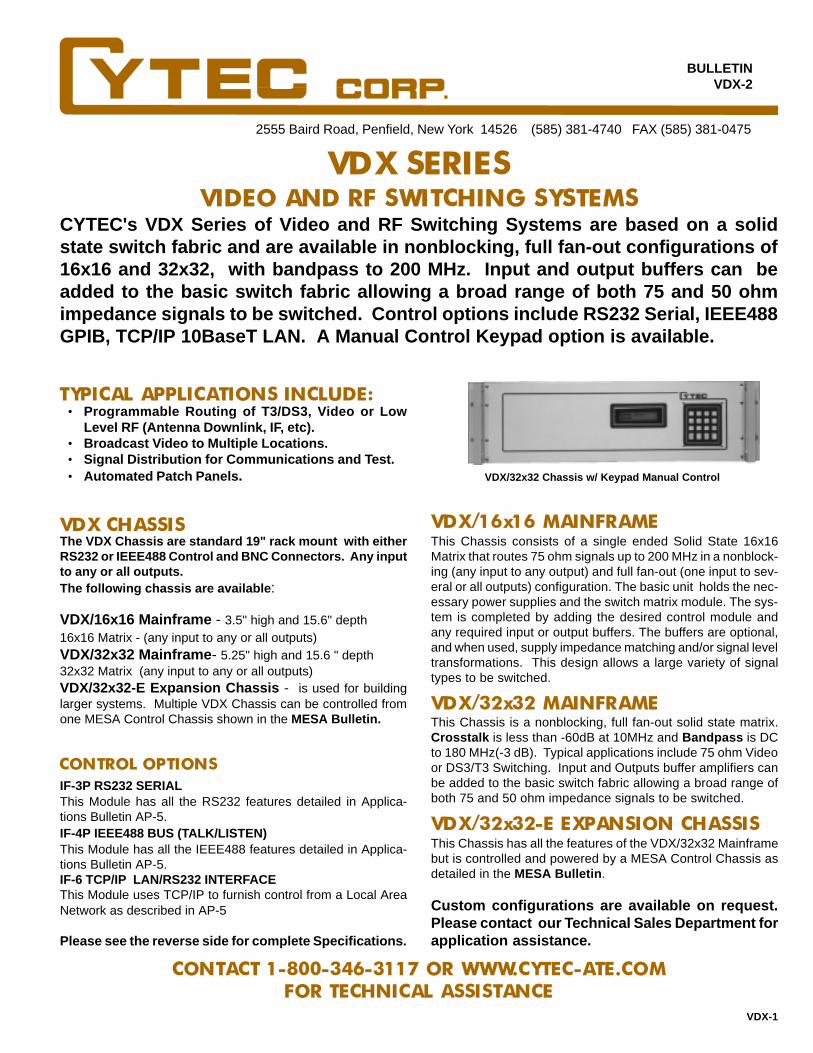
2555 Baird Road, Penfield, New York 14526 (585) 381-4740 FAX (585) 381-0475
BULLETINVDX-2
CONTACT 1-800-346-3117 OR WWW.CYTEC-ATE.COMFOR TECHNICAL ASSISTANCE
VDX SERIESVIDEO AND RF SWITCHING SYSTEMS
CYTEC's VDX Series of Video and RF Switching Systems are based on a solidstate switch fabric and are available in nonblocking, full fan-out configurations of16x16 and 32x32, with bandpass to 200 MHz. Input and output buffers can beadded to the basic switch fabric allowing a broad range of both 75 and 50 ohmimpedance signals to be switched. Control options include RS232 Serial, IEEE488GPIB, TCP/IP 10BaseT LAN. A Manual Control Keypad option is available.
This Chassis consists of a single ended Solid State 16x16Matrix that routes 75 ohm signals up to 200 MHz in a nonblock-ing (any input to any output) and full fan-out (one input to sev-eral or all outputs) configuration. The basic unit holds the nec-essary power supplies and the switch matrix module. The sys-tem is completed by adding the desired control module andany required input or output buffers. The buffers are optional,and when used, supply impedance matching and/or signal leveltransformations. This design allows a large variety of signaltypes to be switched.
VDX/16x16 MAINFRAMEVDX CHASSISThe VDX Chassis are standard 19" rack mount with eitherRS232 or IEEE488 Control and BNC Connectors. Any inputto any or all outputs.The following chassis are available :
CONTROL OPTIONSIF-3P RS232 SERIALThis Module has all the RS232 features detailed in Applica-tions Bulletin AP-5.IF-4P IEEE488 BUS (TALK/LISTEN)This Module has all the IEEE488 features detailed in Applica-tions Bulletin AP-5.IF-6 TCP/IP LAN/RS232 INTERFACEThis Module uses TCP/IP to furnish control from a Local AreaNetwork as described in AP-5
TYPICAL APPLICATIONS INCLUDE:
VDX/32x32 Chassis w/ Keypad Manual Control
Programmable Routing of T3/DS3, Video or LowLevel RF (Antenna Downlink, IF, etc).Broadcast Video to Multiple Locations.Signal Distribution for Communications and Test.Automated Patch Panels .
•
•••
VDX/32x32-E Expansion Chassis - is used for buildinglarger systems. Multiple VDX Chassis can be controlled fromone MESA Control Chassis shown in the MESA Bulletin.
VDX-1
VDX/32x32 MAINFRAME
Please see the reverse side for complete Specifications.
This Chassis is a nonblocking, full fan-out solid state matrix.Crosstalk is less than -60dB at 10MHz and Bandpass is DCto 180 MHz(-3 dB). Typical applications include 75 ohm Videoor DS3/T3 Switching. Input and Outputs buffer amplifiers canbe added to the basic switch fabric allowing a broad range ofboth 75 and 50 ohm impedance signals to be switched.
Custom configurations are available on request.Please contact our Technical Sales Department forapplication assistance.
VDX/16x16 Mainframe - 3.5" high and 15.6" depth16x16 Matrix - (any input to any or all outputs)VDX/32x32 Mainframe - 5.25" high and 15.6 " depth32x32 Matrix (any input to any or all outputs)
VDX/32x32-E EXPANSION CHASSISThis Chassis has all the features of the VDX/32x32 Mainframebut is controlled and powered by a MESA Control Chassis asdetailed in the MESA Bulletin .
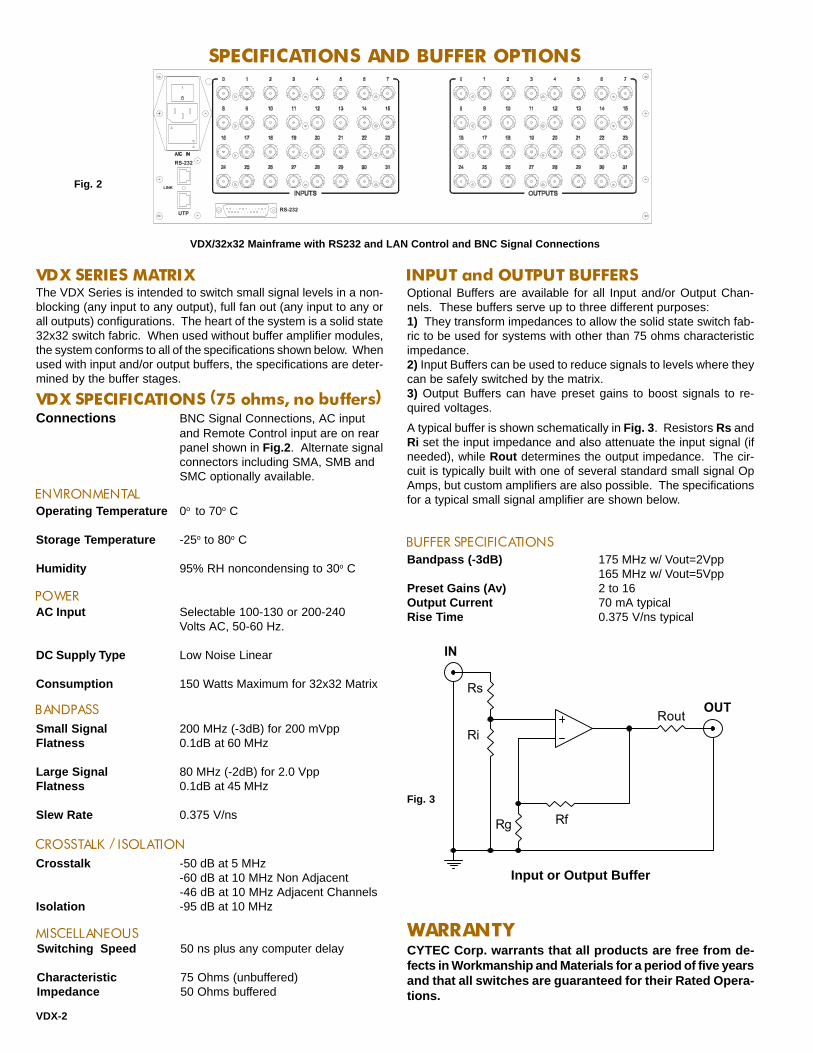
SPECIFICATIONS AND BUFFER OPTIONS
WARRANTY
Connections BNC Signal Connections, AC inputand Remote Control input are on rearpanel shown in Fig.2 . Alternate signalconnectors including SMA, SMB andSMC optionally available.
ENVIRONMENTAL
POWERAC Input Selectable 100-130 or 200-240
Volts AC, 50-60 Hz.
DC Supply Type Low Noise Linear
Consumption 150 Watts Maximum for 32x32 Matrix
VDX SERIES MATRIX
Operating Temperature 0o to 70o C
Storage Temperature -25o to 80o C
Humidity 95% RH noncondensing to 30o C
BANDPASS
CROSSTALK / ISOLATION
Small Signal 200 MHz (-3dB) for 200 mVppFlatness 0.1dB at 60 MHz
Large Signal 80 MHz (-2dB) for 2.0 VppFlatness 0.1dB at 45 MHz
Slew Rate 0.375 V/ns
Crosstalk -50 dB at 5 MHz-60 dB at 10 MHz Non Adjacent-46 dB at 10 MHz Adjacent Channels
Isolation -95 dB at 10 MHz
MISCELLANEOUSSwitching Speed 50 ns plus any computer delay
Characteristic 75 Ohms (unbuffered)Impedance 50 Ohms buffered
VDX/32x32 Mainframe with RS232 and LAN Control and BNC Signal Connections
INPUT and OUTPUT BUFFERSOptional Buffers are available for all Input and/or Output Chan-nels. These buffers serve up to three different purposes:1) They transform impedances to allow the solid state switch fab-ric to be used for systems with other than 75 ohms characteristicimpedance.2) Input Buffers can be used to reduce signals to levels where theycan be safely switched by the matrix.3) Output Buffers can have preset gains to boost signals to re-quired voltages.
Rout
RfRg
Ri
IN
RsOUT
A typical buffer is shown schematically in Fig. 3 . Resistors Rs andRi set the input impedance and also attenuate the input signal (ifneeded), while Rout determines the output impedance. The cir-cuit is typically built with one of several standard small signal OpAmps, but custom amplifiers are also possible. The specificationsfor a typical small signal amplifier are shown below.
BUFFER SPECIFICATIONSBandpass (-3dB) 175 MHz w/ Vout=2Vpp
165 MHz w/ Vout=5VppPreset Gains (Av) 2 to 16Output Current 70 mA typicalRise Time 0.375 V/ns typical
Input or Output Buffer
Fig. 2
Fig. 3
VDX-2
CYTEC Corp. warrants that all products are free from de-fects in Workmanship and Materials for a period of five yearsand that all switches are guaranteed for their Rated Opera-tions.
The VDX Series is intended to switch small signal levels in a non-blocking (any input to any output), full fan out (any input to any orall outputs) configurations. The heart of the system is a solid state32x32 switch fabric. When used without buffer amplifier modules,the system conforms to all of the specifications shown below. Whenused with input and/or output buffers, the specifications are deter-mined by the buffer stages.
VDX SPECIFICATIONS (75 ohms, no buffers)
RS-232UTP
LINK
RS-232
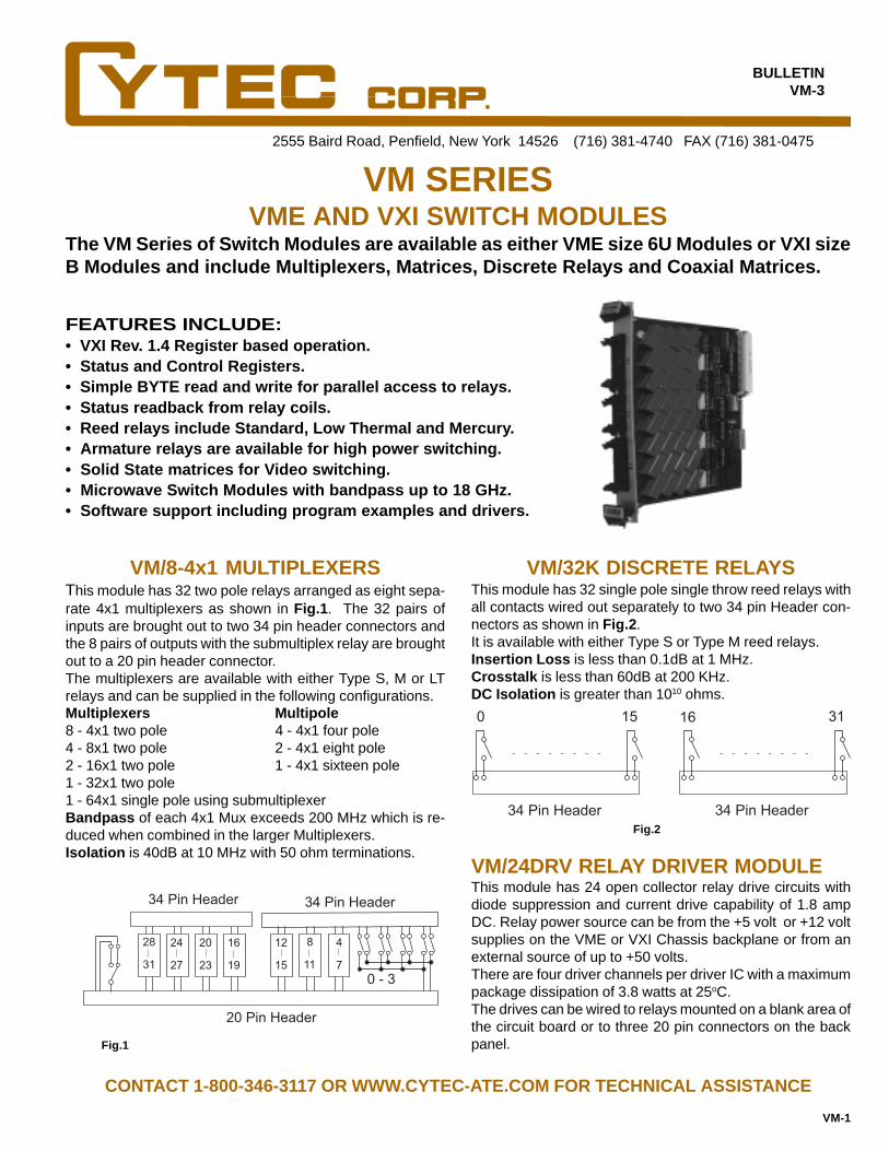
The VM Series of Switch Modules are available as either VME size 6U Modules or VXI sizeB Modules and include Multiplexers, Matrices, Discrete Relays and Coaxial Matrices.
2555 Baird Road, Penfield, New York 14526 (716) 381-4740 FAX (716) 381-0475
VME AND VXI SWITCH MODULESVM SERIES
FEATURES INCLUDE:• VXI Rev. 1.4 Register based operation.• Status and Control Registers.• Simple BYTE read and write for parallel access to relays.• Status readback from relay coils.• Reed relays include Standard, Low Thermal and Mercury.• Armature relays are available for high power switching.• Solid State matrices for Video switching.• Microwave Switch Modules with bandpass up to 18 GHz.• Software support including program examples and drivers.
VM/8-4x1 MULTIPLEXERSThis module has 32 two pole relays arranged as eight sepa-rate 4x1 multiplexers as shown in Fig.1 . The 32 pairs ofinputs are brought out to two 34 pin header connectors andthe 8 pairs of outputs with the submultiplex relay are broughtout to a 20 pin header connector.The multiplexers are available with either Type S, M or LTrelays and can be supplied in the following configurations.Multiplexers Multipole8 - 4x1 two pole 4 - 4x1 four pole4 - 8x1 two pole 2 - 4x1 eight pole2 - 16x1 two pole 1 - 4x1 sixteen pole1 - 32x1 two pole1 - 64x1 single pole using submultiplexerBandpass of each 4x1 Mux exceeds 200 MHz which is re-duced when combined in the larger Multiplexers.Isolation is 40dB at 10 MHz with 50 ohm terminations.
VM/32K DISCRETE RELAYSThis module has 32 single pole single throw reed relays withall contacts wired out separately to two 34 pin Header con-nectors as shown in Fig.2 .It is available with either Type S or Type M reed relays.Insertion Loss is less than 0.1dB at 1 MHz.Crosstalk is less than 60dB at 200 KHz.DC Isolation is greater than 1010 ohms.
CONTACT 1-800-346-3117 OR WWW.CYTEC-ATE.COM FOR TECHNICAL ASSISTANCE
Fig.1
VM/24DRV RELAY DRIVER MODULEThis module has 24 open collector relay drive circuits withdiode suppression and current drive capability of 1.8 ampDC. Relay power source can be from the +5 volt or +12 voltsupplies on the VME or VXI Chassis backplane or from anexternal source of up to +50 volts.There are four driver channels per driver IC with a maximumpackage dissipation of 3.8 watts at 25oC.The drives can be wired to relays mounted on a blank area ofthe circuit board or to three 20 pin connectors on the backpanel.
20 Pin Header
34 Pin Header34 Pin Header
0 - 3
4
7
8
11
12
15
16
19
20
23
24
27
28
31
Fig.2
0 15
34 Pin Header
16 31
34 Pin Header
BULLETINVM-3
VM-1
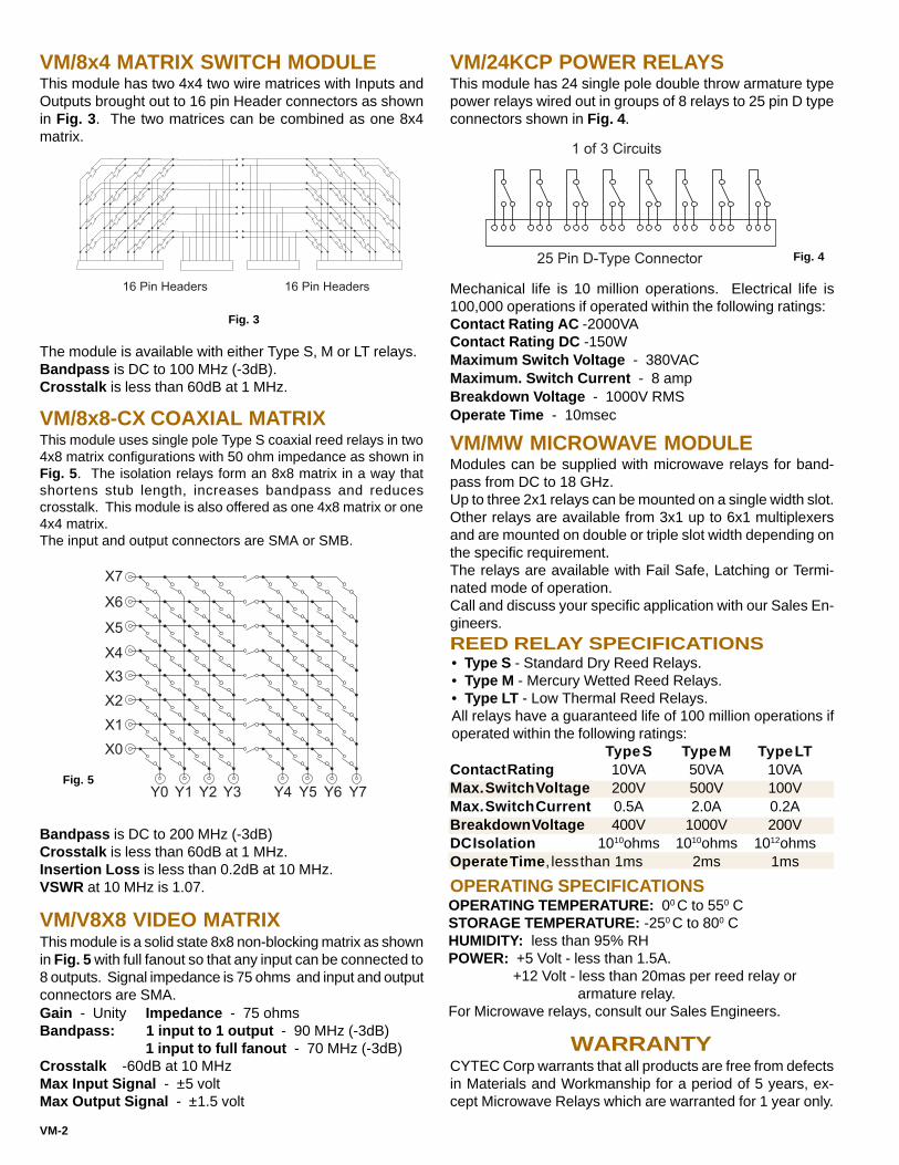
WARRANTYCYTEC Corp warrants that all products are free from defectsin Materials and Workmanship for a period of 5 years, ex-cept Microwave Relays which are warranted for 1 year only.
OPERATING TEMPERATURE: 00 C to 550 CSTORAGE TEMPERATURE: -250 C to 800 CHUMIDITY: less than 95% RHPOWER: +5 Volt - less than 1.5A.
+12 Volt - less than 20mas per reed relay or armature relay.
For Microwave relays, consult our Sales Engineers.
OPERATING SPECIFICATIONS
VM/8x4 MATRIX SWITCH MODULEThis module has two 4x4 two wire matrices with Inputs andOutputs brought out to 16 pin Header connectors as shownin Fig. 3 . The two matrices can be combined as one 8x4matrix.
The module is available with either Type S, M or LT relays.Bandpass is DC to 100 MHz (-3dB).Crosstalk is less than 60dB at 1 MHz.
VM/8x8-CX COAXIAL MATRIXThis module uses single pole Type S coaxial reed relays in two4x8 matrix configurations with 50 ohm impedance as shown inFig. 5 . The isolation relays form an 8x8 matrix in a way thatshortens stub length, increases bandpass and reducescrosstalk. This module is also offered as one 4x8 matrix or one4x4 matrix.The input and output connectors are SMA or SMB.
Bandpass is DC to 200 MHz (-3dB)Crosstalk is less than 60dB at 1 MHz.Insertion Loss is less than 0.2dB at 10 MHz.VSWR at 10 MHz is 1.07.
VM/24KCP POWER RELAYSThis module has 24 single pole double throw armature typepower relays wired out in groups of 8 relays to 25 pin D typeconnectors shown in Fig. 4 .
Mechanical life is 10 million operations. Electrical life is100,000 operations if operated within the following ratings:Contact Rating AC -2000VAContact Rating DC -150WMaximum Switch Voltage - 380VACMaximum. Switch Current - 8 ampBreakdown Voltage - 1000V RMSOperate Time - 10msec
VM/V8X8 VIDEO MATRIXThis module is a solid state 8x8 non-blocking matrix as shownin Fig. 5 with full fanout so that any input can be connected to8 outputs. Signal impedance is 75 ohms and input and outputconnectors are SMA.
VM/MW MICROWAVE MODULEModules can be supplied with microwave relays for band-pass from DC to 18 GHz.Up to three 2x1 relays can be mounted on a single width slot.Other relays are available from 3x1 up to 6x1 multiplexersand are mounted on double or triple slot width depending onthe specific requirement.The relays are available with Fail Safe, Latching or Termi-nated mode of operation.Call and discuss your specific application with our Sales En-gineers.
Gain - Unity Impedance - 75 ohmsBandpass: 1 input to 1 output - 90 MHz (-3dB)
1 input to full fanout - 70 MHz (-3dB)Crosstalk -60dB at 10 MHzMax Input Signal - ±5 voltMax Output Signal - ±1.5 volt
Fig. 3
Fig. 4
Fig. 5
16 Pin Headers 16 Pin Headers
X7
X6
X5
X4
X3
X2
X1
X0
Y0 Y1 Y2 Y3 Y4 Y5 Y6 Y7
25 Pin D-Type Connector
1 of 3 Circuits
• Type S - Standard Dry Reed Relays.• Type M - Mercury Wetted Reed Relays.• Type LT - Low Thermal Reed Relays.All relays have a guaranteed life of 100 million operations ifoperated within the following ratings:
REED RELAY SPECIFICATIONS
VM-2
Type S Type M Type LTContact Rating 10VA 50VA 10VAMax. Switch Voltage 200V 500V 100VMax. Switch Current 0.5A 2.0A 0.2ABreakdown Voltage 400V 1000V 200VDC Isolation 1010ohms 1010ohms 1012ohmsOperate Time , less than 1ms 2ms 1ms

2555 Baird Road, Penfield, New York 14526 (585) 381-4740 Fax (585) 381-0475
BULLETINVX-5
VX SERIESSWITCHING SYSTEMS
FOR AUTOMATIC TEST, INSTRUMENTATION AND COMMUNICATIONS
VX/256 MAINFRAMESThe Mainframes are 19" rack mounting units 5.25" high and 12"deep with power supplies and motherboards to accept up to 16VX Switch Modules, Display Modules and a Control Module.These modules plug into the mainframes so that signal inputsare accessible on the back panel and the LED displays arevisible through the translucent front panel.The Mainframes accept any of the VX Switch Modules.
The VX Series of low-cost, versatile Switching Systems use a modular concept of Switch Modules,Display Modules and Control Modules which can be assembled into VX/256 Mainframes as Matrices,Multiplexers or Individual Relays.All units have front panel LED displays and Status feedback of selected relays.Control Modules are available for IEEE488 Bus, RS232 Serial, 10Base-T Ethernet LAN, and optionalFront Panel Manual Controls.
VX/256-E EXPANSION CHASSISThese units have the same prewired motherboards as the main-frames but do not have power supplies or control modules. Theyare powered and controlled from the MESA Control Unit as de-tailed in the MESA Bulletin.
VX/256-W WIRED UNITSAll mainframes and expansion chassis can be supplied in 16"deep chassis with modules wired out to user specified connec-tors in any required configuration.
SWITCH MODULESEach Switch Module has sixteen relays and each relay can beindividually latched or unlatched and the Status displayed bythe CL16 Display Module.The following Switch Modules are available:
VX/4(1X4) MODULEThis versatile module has four 1x4 two pole matrices which canbe configured as two 1x8 Matrices or one 1x16 module.
These modules have 16 relays with inputs on header connec-tors and outputs bussed on the motherboard.VX16/G2 has 16 two pole relays.VX16/G3 has 16 three pole relays.VX16/GC has 16 single pole Form C relays.
VX/G MODULES
VX/K MODULESThese modules have 16 individual relays and are not bussed tothe motherboard.VX/KA has 16 single pole Form A relays.VX/KC has 16 single pole Form C relays.
VXC MODULESThese modules are high frequency coaxial matrices with SMAconnectors.VXC/4x4 has 16 single pole coaxial relays arranged in a 4x4configuration.VXC/8x2 has 16 single pole coaxial relays arranged in an 8x2configuration.
CL16 DISPLAY MODULESOne Display Module is required for each Switch Module. It hasthe controls for selecting and Latching or Unlatching the 16 re-lays in the Switch Module. Sixteen LEDs in series with therelays give an absolute indication that the relays are energized.The LEDs are visible through the front panel and are a valuableaid in checking the matrix status.The CL16 also includes Status Feedback to the computer toverify that selected relays are energized by checking the relaydrive output.
VX/256 Mainframe with Manual Controls
VX-1
IEEE 488 BUS
RS232 SERIAL
PC I/O PORT
LAN

Fig. 3
VX/256 CHASSISThe VX/256 Chassis consist of Mainframes and Expansion Chassis with pre-wired motherboardswhich accept 16 of the VX Switch Modules and Display Modules.The motherboards are assembled so that the Switch Module signal connectors are accessible fromthe chassis back panel and the LEDs are visible through the front panel.The VX/256 Mainframes have power supplies and are pre-wired for a Control Module.The VX/256-E Expansion Chassis are powered and controlled from the MESA Control Unit detailedin MESA Bulletin.
VX MATRIX SWITCH MODULE
SWITCH MODULE CONFIGURATIONS
MATRIX CONFIGURATIONS
These modules have 16 two pole relays arranged as four 1x4 matrices as shown in Fig. 1. One side of each matrixis wired to signal connectors and the other side is wired to card edge connectors which plug into the VX/256Signal Motherboard. The signal connectors available include BNC, 3 pin Header or Screw Terminals.The modules are available with Type S, M or LT reed relays.
The basic Switch Module shown in Fig. 1 includes buspoints A, B and C which allows the module to be config-ured as either a VX/4(1x4), VX/2(1x8) or VX/1x16 Module.VX/4(1x4) Module has no bussing and configures as four 1x4matrices. Allows formation of 4x4 through 64x4 Matrices.VX/2(1x8) Module is bussed at points A & C to form two 1x8matrices. Allows formation of 2x8 through 32x8 Matrices.VX/1x16 Module is bussed at bus points A, B & C to form one1x16 matrix. Allows formation of 1x16 through 16x16 Matrices.
Fig. 1
Fig. 4
Four 16x4 Matrices can be configured without any bussing asshown in Fig. 2 .Two 32x4 Matrices can be configured by bussing between Ma-trices 1 & 2 and between Matrices 3 & 4 in Fig. 2 .One 64x4 Matrix can be configured by bussing between Matri-ces 1, 2, 3 & 4 in Fig.2 .
Several different Matrix configurations can be assembled in the VX/256 Chassis using the three different VXMatrix Switch Modules and by bussing on the Signal Motherboard.Bandpass is DC to 10 MHz and Isolation is better than -60dB at 1 MHz.
VX/4(1x4) CONFIGURATIONSTwo 16x8 Matrices s can be configured as shown in Fig. 3without bussing the Motherboard.One 32x8 Matrix can be configured by bussing between Matri-ces 1 & 2 in Fig. 3 .
VX/2(1X8) CONFIGURATIONS
VX/1x16 CONFIGURATIONSOne 16x16 Matrix can be configured as shown in Fig. 4 with-out bussing the motherboard.
Fig. 2
0
1
2
3
A
B
C
0 1 2
4
5
6
7
0
1
2
3
14 15
8
9
10
11
12
13
14
15
0 1 2
0
1
2
3
14 15
0
1
2
3
0
1
2
3
0
1
2
3
1
2
3
4
0 1 2
4
5
6
7
0
1
2
3
14 15
0 1 2
4
5
6
7
0
1
2
3
14 15
1
2
VX-2

VX16/G3 has 16 three pole relays wired out to a 50 pin headerand is available with Type S, M , or LT reed switches.
VX16/GC has 16 single pole, Form C relays wired out to two 20pin header connectors as shown in Fig. 6 .These modules are available with Type CS relays.
VX GENERAL PURPOSE MODULESVX/G SWITCH MODULES
VXC/4X4 COAXIAL SWITCH MODULE
VX/K SWITCH MODULES
VXC/8X2 COAXIAL SWITCH MODULE
These modules have the inputs of 16 relays wired to headerconnectors on the rear edge of the module and the outputswired to the motherboard as shown in Figs. 5 & 6 .Plugged into the bussed motherboard, the modules can be wiredin configurations of 16x16, 32x8, 64x4, 128x2 or 256x1 .The following types of modules are available:VX16/G1 has 16 single pole relays wired to two 20 pin headersas shown in Fig. 5 and is available with Type S or M reed re-lays.VX16/G2 has 16 two pole relays wired to two 20 pin headers asshown in Fig. 5 and is available with Type S, M or LT reedrelays.
These modules have 16 individual relays with both inputs andoutputs brought out to header connectors on the rear of themodule. There are no connections to the motherboard, andthese modules can be used in any combination with other VXmodules.There are two types of modules:VX/KA has 16 Form A relays wired out to two 20 pin headerconnectors as shown in Fig. 7 . It is available with both Type Sor M reed switches.VX/KC has 16 Form C relays wired out to a 50 pin headerconnector as shown in Fig. 8 . It is available with both Type CSor CM reed switches.
This module has 16 single pole coaxial relays interconnectedby 50 ohm characteristic impedance striplines in an 8x2 matrixconfiguration as shown in Fig. 10 .The inputs are wired out to SMA connectors on the rear of themodule.The outputs are switched through isolation relays to two SMAconnectors on the back panel and to the card edge connectorwhich plugs into a coaxial motherboard.Bandpass is DC to 200 MHz (-3dB).Crosstalk and Isolation are better than 60 dB at 10 MHz.When plugged into the coaxial motherboard, the bandpass isdependent on matrix size due to the stub length, and in a 128x2matrix, the bandpass is 50 MHz.
This module has 16 single pole coaxial relays interconnectedby 50 ohm characteristic impedance striplines in a 4x4 matrixconfiguration as shown in Fig. 9 . The inputs and outputs arewired out to coaxial connectors on the rear of the module whichcan be SMA, SMB or Coaxicon . There are no connections tothe motherboard.Bandpass is DC to 400 MHz (-3dB).Crosstalk and Isolation are better than 60 dB at 10 MHz.
Fig.9
Fig. 10
Fig. 7 Fig. 8
Fig. 6
Fig. 5
0 1 2 3 4 5 6 7 8 9 10 11 12 13 14 15
0 1 2 3 4 5 6 7 8 9 10 11 12 13 14 15
0
1
2
3
4
5
6
7
8
9
10
11
12
13
14
15
0
1
2
3
4
5
6
7
8
9
10
11
12
13
14
15
X0
X1
X2
X3
Y0
Y1
Y2
Y3
VX-3
01
23
45
67
89
1011
1213
1415
Y0
Y1
X0
X1
X2
X3
X4
X5
X6
X7

MATING CONNECTORSJ3 - Three pin crimp type header connector.J3ST - Three screw terminal type header connector.J20-R - Twenty pin ribbon type header connector.J20-C - Twenty pin crimp header connector.J50-R - Fifty pin ribbon cable type header connector.J50-C - Fifty pin crimp type header connector.
CABLESCBL-0.5 IEEE488 Cable .5 meters long.CBL-1 IEEE488 Cable 1 meter long.CBL-2 IEEE488 Cable 2 meters long.RS-1 RS232 Cable 2 meters long.Cables and wired chassis can be built to customers specificrequirements. Please contact our Sales Staff for more informa-tion.
CHASSIS SLIDES
CHS-1 Pairs of 19" rack mounting chassis slides with 15" travel.
CABINETSPortable cabinets with handles for 19" rack mounted units with10.5" panel spaces and 21" depth.
MANUAL CONTROLS
This manual control consists of thumbwheels and toggleswitches on the front panel for switchpoint and mode selection.A Strobe pushbutton enters the data.These controls can be "locked out" by the computer.
CONTROL MODULES
DIMENSIONS - 19" Rack Mounting, 5.25" high and 12" deep.WEIGHT - With full complement of Modules - 25 lbs.POWER - 100-130 Volts AC or 200-240 Volts AC 50-60 Hz, 100VA.ENVIRONMENT - Operating at 00 C to 500 C.
Storage at -250 C to 650 C.
WARRANTYCYTEC Corp. warrants that all products are free from defects inMaterial and Workmanship for a period of 5 years and that allswitches are guaranteed for their Rated Operations.
The relays use high reliability reed switches with a guaranteedlife of 100 million operations when used within the followingspecifications:Type S and CS Standard switches are for general purpose in-strumentation level signals.Type M and CM Mercury switches are for higher power switch-ing.Type LT Low Thermal switches have offset of less than onemicrovolt for very low signal level measurements.
GENERAL SPECIFICATIONS
M/256 MANUAL CONTROL
VX SERIES RELAY SPECIFICATIONS
ACCESSORIES
VX-4
VMCS VIRTUAL MANUAL CONTROL SOFTWAREThis Software displays a full Graphical User Interface (GUI) onthe controlling computer. The operator controls the Mainframewith simple mouse point-and-click operations. The software canalso be used to control the unit over a LAN.Windows based software is free with any purchase.A demo version is available on our web site at: http://www.cytec-ate.com/soft.htm
IF-1 PARALLEL PORTThis module requires 14 individual TTL level binary lines fromthe controlling computer. These select Switch and Mode, Strobethe selected command and return switch point Status.
GX GROUP SWITCHVX16/G2 & VX16/G3 Switch Modules can be used in theGX/16 Group Switch Chassis to switch signals in groupsof up to 48 wires in up to a 16x1 Multiplexer configuration.For more information see GX Bulletin.
CONTACT 1-800-346-3117 OR WWW.CYTEC-ATE.COM FOR TECHNICAL ASSISTANCE
The VX Mainframes can be computer controlled via the mod-ules listed below. Each Control Module selects anyswitchpoint and Latches, Unlatches and returns Status ofthat point.
This module combines both the IEEE488 Talk/Listen and theRS232 features detailed in the AP-5 Bulletin.
IF-5 IEEE488/RS232
IF-6 LAN INTERFACEThis module allows control via a 10Base-T Ethernet LAN usingTCP/IP protocol detailed in the AP-5 Bulletin.SPECIFICATIONS S M LT CS CM
Contact Rating VA 10 50 10 3 30Switching Voltage DC 200 500 100 200 350Switching Current DC .5A 1.0A .25A .25A 1.0ACarrying Current DC 1.0A 2.0A 1.0A 1.0A 2.0ABreakdown Voltage DC 400 1000 400 200 1000Operate Time MSec 1 2 1 1.5 3
CUSTOM SYSTEMS
Drivers and Sample Programs are available for the most com-mon programming languages. These check the entire systemby cycling through all switches, sequentially latching and un-latching each switch while checking Status.
SOFTWARE
CYTEC Corp. can build Group Switches using a variety ofSwitch Modules, Connectors or mixtures of signal types. Ifyou do not see what you need for your application, pleasecontact us and give us the opportunity to recommend a solu-tion.

LOW COST SOLUTIONS FROM THE SWITCHING SPECIALISTS.• MATRICES • MULTIPLEXERS • POWER RELAYS
• COAXIAL MATRICES • CUSTOM MODULES.
2555 Baird Road, Penfield, New York 14526
FOR TECHNICAL ASSISTANCE or aFULL PRODUCT CATALOG,
CONTACT1-800-346-3117 or
www.cytec-ate.com [email protected]
Member of the
Alliance
SWITCHING SYSTEMS
Full
Assortment of
C Size VXI
Switch Modules
B Size
Modules and
VME Modules
also available

The CY Series are low cost C-Size VXI Bus Switch Modules that utilize both Message and Regis-ter based operation. Available modules include Multiplexers, Matrices, Microwave Switches,Individual Form A and Form C Relays, Driver Modules, 50 Ohm Coaxial, Solid State and ECLMatrices.
FULL FIVE YEAR WARRANTY
STATUS of individual relays monitored at the relay
drives.
HIGH RELIABILITY Type S Standard and Type M Mer-
cury Wetted Reed Relays with a guaranteed life of
100 million operations.
LOW THERMAL Relays with offsets less than 1 Fvolt.
MICROWAVE Switches with a Bandpass of DC to 18
GHz; 26 GHz optionally available.
HIGH FREQUENCY 50 ohm impedance 8x8 Coaxial
Matrix with 200 MHz bandpass.
HIGH POWER Switch Modules with 32 Form C Arma-
ture Relays with 150 W or 2000 VA rating.
MULTIPLEXERS with up to 128 switch points.
HIGH DENSITY BIDIRECTIONAL MATRICES up to
16x8 or 62x2 configurations.
"K" MODULES with 64 individual Form A or Form C
relays.
SOLID STATE 48x48 Matrices.
ECL 16x16 Differential Pair Matrix.
BUFFER Amplifier Modules with unity gain for im-
pedance matching.
DIFFERENTIAL INSTRUMENTATION Amplifiers with
preset gains.
DRIVER MODULES with individual current sourcing
or sinking drives.
SOFTWARE
GENERAL SPECIFICATIONS
2555 Baird Road, Penfield, New York 14526 (585) 381-4740 FAX (585) 381-0475
CY SERIESVXI C-SIZE SWITCH MODULES
BULLETINCY/10
CYTEC Corp. warrants that all products are free from de-fects in workmanship and materials for a period of 5 years.Reed relays are guaranteed for 100 million operations whenused within their published specifications. However, Micro-wave switches are warranted for 1 year.
WARRANTY
Member of the VXI Plug and Play Alliance..
FEATURES INCLUDE:•
•
•
•
•
•
•
•
•
•
•
•
•
•
•
VXI Revision 1.4Logical Address Per DIP Switch SettingRadiated Emissions Per VXI SpecificationConducted Emissions Per VXI Specification
ENVIRONMENTALOperating Temperature 0º to 55ºCStorage Temperature -25º to 80ºCHumidity Less than 95% RH no
condensation to 30ºCCooling <10ºC rise w/air flow 1.5
L/sec & dP = 0.04 mm H2O
Drivers and/or sample programs are available in the mostcommon programming languages. Please consult our ex-pert Sales Engineers.
FOR TECHNICAL ASSISTANCE CONTACT 1-800-346-3117 or WWW.CYTEC-ATE.COM

CY SERIES RELAY SPECIFICATIONS
CY/128 - These are built with 64 two-pole reed relays. InternalPin Jumpers permit a variety of user-defined configurations,ranging from eight individual 8x1 two-pole multiplexers to one128x1 single pole mux.CY/8x8 - This 8 Input/8 Output Matrix Switch Module is avail-able with either single or two pole reed relays.CY/16x8 - This is a 16 Input/8 Output Matrix that is built withType A armature relays and is used for switching instrumenta-tion level signals.CY/64x2 - This holds 128 single pole reed relays arranged aseight individual 8x2 matrices. Many other configurations arepossible, including the "standard" 64x2.CY/64K - This provides 64 individual Form A (NO) Reed Re-lays.CY/64KC - This supplies 64 separate Form C (NO/COM/NC)Type A Instrumentation Armature Relays.CY/32KCP - This is built with 32 Individual Form C Type PPower Relays for high power/current applications.CY/CX - This is a 50 ohm impedance 8x8 matrix which is de-signed to switch RF signals. Bandpass (-3dB) is 200 MHz.CY/G and CY/M - These switch microwave signals (DC-18GHz). These one, two or three slots modules are built to theuser's specifications and hold the CXR/1G and CXM SeriesSwitch Modules.
CY/48x48 - This 48x48 single pole matrix designed to switch±5 volt signals. Bandpass is DC to 1 MHz, and path on resis-tance is 60 ohms.CY/16x16ECL - This provides a 16x16 nonblocking matrix forswitching Differential ECL up to 1.2GBPS.CY/IO-48 - This holds 48 unity gain impedance matching bufferamplifiers.CY/INST-48 - This holds 48 precision differential input op amps.These have high input and low output impedances and makean ideal buffer into the CY/48x48 Solid State VXI Matrix.
•
•
•
•
•
•
•
•
•
CY SERIES MODEL OVERVIEW
•
•
•
•
• Type S - Standard Dry Reed Relays.• Type M - Mercury Wetted Reed Relays.• Type LT - Low Thermal Reed Relays.• Type P - Armature Power Relays.• Type A - Instrumentation Level Signal Armature Relays.Relays have the following guaranteed lifetimes when operatedwithin the specified operating parameters.
Solid State Modules
CYTEC currently offers the following Models/Configurations:Relay Modules (Note: All Relay Modules are bidirectional.)
MICROWAVE RELAYSThese CY/G and CY/M Modules are available as indi-vidual relays or as multiplexers or wired in a variety ofdifferent configurations including matrices. Please con-tact our Sales Department for information.
Relay Type S M LT P AMin. Life - Mechanical 108 108 108 107 108
Min. Life - Full Load* 108 108 108 2x10⁵ 2x10⁵
Contact Rating VA 10 50 10 2000 30Switch Voltage 200V 500V 100V 380V 110VMax. Switch Current 0.5A 2.0A 0.2A 8A 1.0AMax. Carry Current 1.0A 2.0A 1.0A 10A 1.0ABreakdown Voltage 400V 1000V 200V 1000V 750VOperate Time <1ms <2ms <1ms <15ms <3msDC Isolation - Ohms 1011 1011 1012 109 109
*Load is purely resistive
AD DATA SWITCH MODULESCYTEC Corp is offering support, repair, serviceand replacement of AD Data VXI Modules.230114-111 - Single pole, Standard Reed Relays. 64SPST Switches; 64 Discrete Switches, 0.5 amp.230114-112 - Single pole, Mercury Relays, 64 SPSTSwitches; 64 Discrete Switches, 2.0 amp.230115-111 - Single pole, Standard Reed Relays, 64x1Multiplexer Switch 0.5 amp.230115-112 - Single pole, Mercury Relays, 64x1 Multi-plexer Switch 2.0 amp.230115-121 - Double pole, Standard Reed Relays, 64x1Multiplexer Switch 0.5 amp.230115-122 - Double pole, Mercury Relays, 64x1 Multi-plexer Switch 2.0 amp.230115-123 - Double pole, Low Thermal Relays, 64x1Multiplexer Switch.230116-111 - Single pole, Standard Reed Relays, 16x4Matrix Switch 0.5 amp.230116-112 - Single pole, Mercury Relays, 16x4 MatrixSwitch 2.0 amp.230116-121 - Double pole, Standard Reed Relays, 16x4Matrix Switch 0.5 amp.230116-122 - Double pole, Mercury Relays, 16x4 MatrixSwitch 2.0 amp.230126-123 - Double pole, Low Thermal Relays, 16x4Matrix Switch 0.5 amp.230117-111 - Single pole, Standard Reed Relays, Regis-tered based 96 (1x1) Switch Module 0.5 amp.230117-112 - Single pole, Mercury Relays, Registeredbased 96 (1x1) Switch Module 2.0 amp.230118-111 - Single pole, Standard Reed Relays, Regis-tered based 24 (4x1x1) Switch Module 0.5 amp.230118-112 - Single pole, Mercury Relays, Registeredbased 24 (4x1x1) Switch Module 2.0 amp.230119-111 - Single pole, Standard Reed Relays, 6 (1x4)Coaxial 1 Gigahertz Switch Module.230120-115 - Single pole, Armature Relays, 20 SPST10 amp, Register-based Power Switch Module.230120-125 - Double pole, Armature Relays, 20 SPSTor 10 DPST 10 amp, Register-based Power Switch Mod-ule.230122-111 - Single pole, Standard Reed Relays, Regis-tered based 12 (4x1) and 48(1x1) Switch Module 0.5 amp.230122-112 - Single pole, Mercury Relays, Registeredbased ARINC 608A 2 (4x1x1) and 48(1x1) Form A 2ASwitch Module.230131-123 - Double pole, Low Thermal Relays, Regis-tered based ARINC 608A Form A Resource DistributorSwitch Module.230132-123 - Double pole, Low Thermal Relays, Regis-tered based ARINC 608A 2 (16x4) 4 wire/channel FormA Bus Matrix Input Switch Module.

The CY/128 is a bidirectional reed relay multiplexer and is used in general purposeswitching applications. The module is designed with flexibility in mind, and avariety of different configurations are available. This allows the users to choosethe configuration which most closely matches their requirements. All CYTEC VXIModules use both Message and Register based operation.
The CY/128 Multiplexer holds eight individual 8x1 two-pole multiplexers and four single pole submultiplexer re-lays. Pin jumpers can be installed to interconnect theindividual multiplexers, allowing the following configu-rations to be created:
Power +5 Volts less than 1.0 Amp+12 Volts 20 mA per energized relay
Bandpass (8x1) DC to 80 MHz (-3dB)Insertion Loss less than 0.2dB at 10 MHzIsolation/Crosstalk 100 kHz - 80dB
1 MHz - 60dB10 MHz - 40dB
DC Isolation Greater than1010 ohms
BULLETINCY/128
2555 Baird Road, Penfield, New York 14526 (585) 381-4740 FAX (585) 381-0475
CY/128 MULTIPLEXERVXI C-SIZE SWITCH MODULE
• CY/128-S with Type S Standard Dry Reed Relays
• CY/128-M with Type M Mercury Wetted Reed Relays
• CY/128-LT with Low Thermal Offset Reeds
Two 64 Pin Headers (128 Individual "Inputs")One 20 Pin Header (Eight Multiplexer and four Submux "Out-puts")
• Type S - Standard Dry Reed Relays.• Type M - Mercury Wetted Reed Relays.• Type LT - Low Thermal Reed Relays.
Type S Type M Type LTContact Rating 10VA 50VA 10VAMax. Switch Voltage 200V 500V 100VMax. Switch Current 0.5A 2.0A 0.2ABreakdown Voltage 400V 1000V 200VOperate Time, less than 1ms 2ms 1msDC Isolation - Ohms 1011 1011 1012
CYTEC Corp. warrants that all products are free from de-fects in workmanship and materials for a period of 5 years.Reed relays are guaranteed for 100 million operations whenused within their published specifications.
WARRANTY
REED RELAY SPECIFICATIONS
DETAILED DESCRIPTION
Eight - 8x1 Two-Pole MultiplexersFour - 16x1 Two-Pole MultiplexersTwo - 32x1 Two-Pole MultiplexersOne - 64x1 Two-Pole MultiplexerOne - 128x1 Single Wire Multiplexer using two Submulti-plexer RelaysTwo - 64x1 Single Wire Muxes using four Submux RelaysOne - 32x1 Four Wire MultiplexerOne - 16x1 Eight Wire MultiplexerOne - 8x1 Sixteen Wire Multiplexer
Any number of relays can be energized at one time, andthe status of all relays may be read at any time.
•••••
•
•••
AVAILABLE MODELS
CONNECTORS
••
GENERAL SPECIFICATIONS
Member of the VXI Plug and Play Alliance..
FOR TECHNICAL ASSISTANCE CONTACT 1-800-346-3117 or WWW.CYTEC-ATE.COM
20 Pin Header
64 Pin Header 64 Pin Header

The CY/64x2 is a bidirectional reed relay matrix and is designed for general purpose switch-ing applications. The module can be configured in a variety of different ways. The userscan specify the configuration which most closely matches their requirements. All CYTECVXI Modules use both Message and Register based operation.
The CY/64x2 Matrix contains 128 single pole reed relays arranged as eight banks of 8x2 matrices. These banks may beused individually or combined via internal pin jumpers to form larger Nx2 matrices. External wiring added by the user providesmany other configurations, such as two 16x4 matrices or a single 32x4. Any number of relays may be closed simultaneously,and the status of all relays may be read at any time.
POWER +5 Volts, less than 1.2 Amp+12 Volts, 25 mA per relay
BANDPASS DC to 50 MHz (-3dB)- One 8x2 Bank
ISOLATION/CROSSTALK <-50 dB at 10 MHz
BULLETINCY/64x2
2555 Baird Road, Penfield, New York 14526 (585) 381-4740 FAX (585) 381-0475
CY/64x2 SINGLE POLE MATRIXVXI C-SIZE SWITCH MODULE
• CY/64x2-S with Type S Standard Dry Reed Relays.• CY/64x2-M with Type M Mercury Weed Reed Relays.
• Two 34 Pin Headers (128 Individual "Inputs")• One 20 Pin Header (16 total "Outputs" - one from each of eight 8x2 matrices.)
CYTEC Corp. warrants that all products are free from de-fects in workmanship and materials for a period of 5 years.Reed relays are guaranteed for 100 million operations whenused within their published specifications.
RELAY SPECIFICATIONS
DETAILED DESCRIPTION
AVAILABLE MODELS CONNECTORS
SPECIFICATIONS
WARRANTY
FOR TECHNICAL ASSISTANCE CONTACT 1-800-346-3117 or WWW.CYTEC-ATE.COM
Member of the VXI Plug and Play Alliance..
Type S Type MContact Rating 10VA 50VAMax. Switch Voltage 200V 500VMax. Switch Current 0.5A 2.0AMax. Carry Current 1.0A 2.0ABreakdown Voltage 400V 1000VOperate Time, less than 1ms 2msDC Isolation - Ohms 1012 1012
CY/64x2-SOUT 0IN 63 OUT 1IN 0 IN 1

Each of these VXI Switch Modules provides 64 individual switch points. The CY/64K sup-plies 64 Form A reed relays, while the CY/64KC furnishes 64 Form C general purpose arma-ture relays. Any number or relays may be closed simultaneously and relay status may beread at any time. All CYTEC products utilize both Register and Message based operation.
CY/64K holds 64 separate single pole Form C Type S Standard or Type M Mercury reed relays. Each contact set isindividually wired to 34 pin front panel connectors.CY/64KC is built with 64 individual high sensitivity, low thermal offset single pole Form C Type A armature relays forswitching instrumentation level signals. The Normally Open, Normally Closed and Common contacts of all relays arewired out to 50 pin header connectors. Thermal Offsets are less than five microvolts.
BULLETINCY/64K
2555 Baird Road, Penfield, New York 14526 (585) 381-4740 FAX (585) 381-0475
CY/64K & CY/64KCVXI C-SIZE INDIVIDUAL RELAY SWITCH MODULES
POWER +5 Volts, less than 1.2 Amp CY64/K +12V, 15 mA per energ. relay CY64/KC +12V, 20 mA per energ. relayBANDPASS DC to 40 MHz (-3dB)INSERTION LOSS less than 0.1 dB at 1 MHzISOLATION/CROSSTALK less than -40 dB at 1 MHz
RELAY SPECIFICATIONS
• CY/64K-S - Form A Type S Standard Reed Relays• CY/64K-M - Form A Type M Mercury Reed Relays• CY/64KC - Form C Type A Armature Relays
• CY/64K- Four 34 Pin Header Connectors• CY/64KC - Four 50 Pin Header Connectors
FOR TECHNICAL ASSISTANCE CONTACT 1-800-346-3117 or WWW.CYTEC-ATE.COM
WARRANTYCYTEC Corp. warrants that all products are free from de-fects in workmanship and materials for a period of 5 years.Reed relays are guaranteed for 100 million operations whenused within their published specifications.
SPECIFICATIONS
DETAILED DESCRIPTION•
•
AVAILABLE MODELS
CONNECTORS
Member of the VXI Plug and Play Alliance..
Type S Type M Type A
Contact Rating 10VA 50VA 30VAMax. Switch Voltage 200V 500V 110VMax. Switch Current 0.5A 2.0A 1.0AMax. Carry Current 1.0A 2.0A 1.0ABreakdown Voltage 0.5A 2.0A 1.0AOperate Time, less than 1ms 2ms 3msLifetime, Mechanical 108 108 108
Lifetime, Full Load 108 108 2x10⁵
Form C Relays - CY/64KC
Form A Relays - CY/64K
CY/64K CY/64KC

CYTEC's CY/64DRV VXI C-Size Driver Module is built with 64 individually address-able current sourcing or sinking drives and is designed to power external loadssuch as relays or solenoids. The CY/32KCP has 32 Form C Power Relays that canswitch up to 8 A of current and 150 watts DC or 2000 watts AC.
This module has 64 individually controlled drives and is builtwith either current sourcing or sinking ICs. These modulesare typically used to drive solenoids or relays located exter-nal to the VXI Module. Each drive channel is an open col-lector and has integral diode suppression. The drives canbe wired to the VXI Chassis' internal power supply busses orto an external source.The CY/64DRV is configured via an internal DIP Switch tofurnish one of eight different operational modes, supplyingeither 64 randomly controllable drives, one of four differentmultiplexing modes or one of three different group switchtypes. The use of any mode is determined by the switchingapplication. Drive status (on/off) can be verified by the con-trolling computer at any time.
BULLETINCY/DRV
2555 Baird Road, Penfield, New York 14526 (585) 381-4740 FAX (585) 381-0475
CY/64DRV RELAY/SOLENOID DRIVER MODULECY/32KCP FORM C POWER SWITCH MODULE
• CY/64DRV-SNK 64 Channel Current Sinking Driver
• CY/64DRV-SRC 64 Channel Current Sourcing Driver
• Internal 14 Pin Headers - wired out to external loads
This module is built with 32 individually controllable Form CArmature type Power Relays. The Normally Open, NormallyClosed and Common contacts of each relay are individuallywired out to three separate pins on a "D" style connector asshown below. Any number of relays may be closed simulta-neously, and the status of all relays may be read at any timeby the controlling computer.
• CY/32KCP- 32 Form C Power Relays Switch Module
• Four 25 Pin D subs
CY/32KCP SPECIFICATIONSPower +5 V, 1.2 Amp. Max.
+12 V, 25 mA per ener. relayTYPE P RELAY RATINGSSwitching Power 2000VA, 150WSwitching Voltage 380VACSwitching Current 8 Amp.Breakdown Voltage 1200 VRMSOperate Time 10 mSec. Max.Mechanical Life 107 Operations
Control Power +5 Volts, 2.1 A Max.+12 Volts, 0.2A Max.
(not including relay driver)
Drive Power Source SinkMax. Voltage 80 VDC 50 VDCMax. Current per Driver 350 mA 400 mAMax. Current per IC Package 1 Amp 1 Amp
25 Pin D sub Connector
CY/64 DRV C-SIZE DRIVER MODULE
AVAILABLE MODELS
CONNECTORS
CY/64DRV SPECIFICATIONS
Member of the VXI Plug and Play Alliance..
FOR TECHNICAL ASSISTANCE CONTACT 1-800-346-3117 or WWW.CYTEC-ATE.COM
WARRANTYCYTEC Corp. warrants that all products are free from de-fects in workmanship and materials for a period of 5 years.
CY/32KCP POWER SWITCH MODULE
AVAILABLE MODELS
CONNECTORS
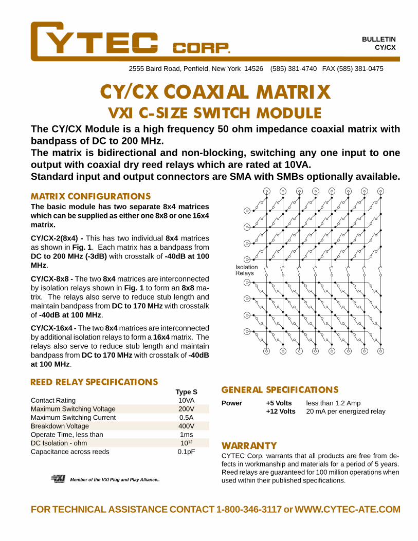
The CY/CX Module is a high frequency 50 ohm impedance coaxial matrix withbandpass of DC to 200 MHz.The matrix is bidirectional and non-blocking, switching any one input to oneoutput with coaxial dry reed relays which are rated at 10VA.Standard input and output connectors are SMA with SMBs optionally available.
The basic module has two separate 8x4 matriceswhich can be supplied as either one 8x8 or one 16x4matrix.
GENERAL SPECIFICATIONS
2555 Baird Road, Penfield, New York 14526 (585) 381-4740 FAX (585) 381-0475
CY/CX COAXIAL MATRIXVXI C-SIZE SWITCH MODULE
REED RELAY SPECIFICATIONS
Member of the VXI Plug and Play Alliance..
WARRANTYCYTEC Corp. warrants that all products are free from de-fects in workmanship and materials for a period of 5 years.Reed relays are guaranteed for 100 million operations whenused within their published specifications.
FOR TECHNICAL ASSISTANCE CONTACT 1-800-346-3117 or WWW.CYTEC-ATE.COM
MATRIX CONFIGURATIONS
Power +5 Volts less than 1.2 Amp+12 Volts 20 mA per energized relay
BULLETINCY/CX
CY/CX-2(8x4) - This has two individual 8x4 matricesas shown in Fig. 1 . Each matrix has a bandpass fromDC to 200 MHz (-3dB) with crosstalk of -40dB at 100MHz.
CY/CX-8x8 - The two 8x4 matrices are interconnectedby isolation relays shown in Fig. 1 to form an 8x8 ma-trix. The relays also serve to reduce stub length andmaintain bandpass from DC to 170 MHz with crosstalkof -40dB at 100 MHz .
CY/CX-16x4 - The two 8x4 matrices are interconnectedby additional isolation relays to form a 16x4 matrix. Therelays also serve to reduce stub length and maintainbandpass from DC to 170 MHz with crosstalk of -40dBat 100 MHz.
Type SContact Rating 10VAMaximum Switching Voltage 200VMaximum Switching Current 0.5ABreakdown Voltage 400VOperate Time, less than 1msDC Isolation - ohm 1012
Capacitance across reeds 0.1pF
IsolationRelays

The CY/8x8 is a general purpose, bidirectional reed relay matrix. It is a true non-blocking matrix, and each input can be connected to one, many or all outputsconcurrently. All CYTEC VXI Modules utilize both Message and Register basedoperation.
The CY/8x8 supplies two individual 8x4 matrices. Thesecan be interconnect externally by the user to provide one8x8 or one 16x4 matrix. This VXI Switch Module is builtwith 64 Reed Relays and is available in either single ortwo pole versions, and with Type S Standard or Type MMercury reeds. It is also available as a two pole matrixwith Type LT Low Thermal reeds. Any number of relayscan be energized concurrently, and the status of all re-lays may be read at any time.
GENERAL SPECIFICATIONS
2555 Baird Road, Penfield, New York 14526 (585) 381-4740 FAX (585) 381-0475
CY/8X8 REED RELAY MATRIXVXI C-SIZE GENERAL PURPOSE SWITCH MODULE
• CY/8x8-1S - Single Pole Type S Standard Reed Relays
• CY/8x8-1M - Single Pole Type M Mercury Wetted Reeds
• CY/8x8-2S - Two Pole Type S Standard Reeds
• CY/8x8-2M - Two Pole Type M Mercury Wetted Reeds
• CY/8x8-LT - Two Pole Low Thermal Reed Relays
• Three 34 Pin Headers
Type S Type M Type LTContact Rating 10VA 50VA 10VAMax. Switch Voltage 200V 500V 100VMax. Switch Current 0.5A 2.0A 0.2ABreakdown Voltage 400V 1000V 200VOperate Time, less than 1ms 2ms 1msDC Isolation - Ohms 1011 1011 1012
REED RELAY SPECIFICATIONS
WARRANTYCYTEC Corp. warrants that all products are free from de-fects in workmanship and materials for a period of 5 years.Reed relays are guaranteed for 100 million operations whenused within their published specifications.
Member of the VXI Plug and Play Alliance..
DETAILED DESCRIPTION
AVAILABLE MODELS
CONNECTORS
• Type S - Standard Dry Reed Relays.• Type M - Mercury Wetted Reed Relays.*• Type LT - Low Thermal Reed Relays.
Power +5 Volts less than 1.0 Amp+12 Volts 20 mA per energized relay
Bandpass DC to 80 MHz (-3dB)Insertion Loss less than 0.2 dB at 10 MHzIsolation/Crosstalk 100 kHz - 80 dB
1 MHz - 60 dB10 MHz - 40 dB
DC Isolation Greater than1010 ohms
* Must be operated in vertical position
34 Pin Header
34 Pin Header
34 P
in H
eade
r
BULLETINCY/8x8
FOR TECHNICAL ASSISTANCE CONTACT 1-800-346-3117 or WWW.CYTEC-ATE.COM

The CY/16x8 is a two pole, bidirectional armature relay matrix that is used to switchinstrumentation level signals. It is a true non-blocking unit, and each input cansimultaneously be connected to one, many or all outputs. All CYTEC VXI SwitchModules utilize both Message and Register based operation.
The CY/16x8 is built with 128 two pole Type A ArmatureRelays and is designed to be used for switching instru-mentation level signals. The relays are organized as six-teen rows in the Y direction and eight columns in the Xdirection. All switching paths are two wires with inte-gral grounds located between all path pairs. Statuschecking of any input reports all connected outputs, andany number of relays can be energized at one time.
Power +5 Volts less than 1.2 Amp+12 Volts 25 mA per energ. relay
Bandpass DC to 50 MHz (-3dB)Insertion Loss less than 0.2dB at 10 MHzIsolation/Crosstalk less than -50dB at 10 MHz
2555 Baird Road, Penfield, New York 14526 (585) 381-4740 FAX (585) 381-0475
CY/16X8 ARMATURE RELAY MATRIXVXI C-SIZE GENERAL PURPOSE SWITCH MODULE
• Three 20 Pin Headers
Type AContact Rating 30W, 62.5VAMaximum Switched Voltage 110VDC, 125VACMaximum Switched Current 1.0ABreakdown Voltage 750VrmsOperate Time 2msecRelease Time 1msecLifetime, Resistive Load Mechanical 108 Operations 1A, 30VDC 2x10⁵ Operations 0.5A, 125VAC 105 OperationsContact Resistance 50 milliohm max.DC Isolation - Ohms 109
TYPE A ARMATURE RELAY SPECIFICATIONS
WARRANTY
Member of the VXI Plug and Play Alliance..
BULLETINCY/16x8
DETAILED DESCRIPTION
CONNECTORS
SPECIFICATIONS
20 Pin Header
Two
20 P
in H
eade
rs
FOR TECHNICAL ASSISTANCE CONTACT 1-800-346-3117 or WWW.CYTEC-ATE.COM
CYTEC Corp. warrants that all products are free from de-fects in workmanship and materials for a period of 5 years.

CY/G AND CY/M C-SIZE VXIMICROWAVE SWITCH MODULES
BULLETINCY/MW
The CY/G and CY/M Series of Microwave Switch Modules have user defined con-figurations and are used to switch RF Signals. Bandpasses of approximately 1.0,18 and 26 GHz can be provided, and characteristic impedances of either 50 or 75ohms are available.
2555 Baird Road, Penfield, New York 14526 (585) 381-4740 FAX (585) 381-0475
These Modules are one or two slot wide C-Size VXI Switch Modules which are built inaccordance with the end users needs. Two basic series are available: The CY/G SwitchModules that furnish a bandpass of about 1 GHz, and the CY/M Switch Modules thattypically have a bandpass of 18 GHz, with 26 GHz optionally available.
• CY/G One Gigahertz VXI Switch Modules• CY/M Microwave VXI Switch Modules
The CY/G VXI Switch Modules are assembled using the CXR/2x1-1G, CXR/4x1-1G, CXR/8x1-1G, and CXR/4x2-1G Gi-gahertz Switch Cards. These cards provide a bandpass ofapproximately DC to 1 Gigahertz. Multiple cards can beplaced in one VXI module, with the number of cards typicallylimited only by the available VXI panel area.
The CY/M VXI Switch Modules are used for switching micro-wave signals. These are one or two slots wide and are builtwith either the CXM/2x1 A/B Switches or the CXM/Nx1 Ro-tary Microwave Switches. A bandpass of DC to 18 GHz isstandard, with DC to 26 GHz optionally available. As an ex-ample, six CXM/6x1 Switches can be fitted into a single two-slot VXI Switch Module.
CXR/8x1-1G - Typical of a GHz Switchused in CY/G VXI Switch Modules.
Power+5 Volts, 2.1 A Max.+12 Volts, 0.2A Max.
Relay Drive PowerDependent on type of Microwaverelays required.
MICROWAVE SWITCH MODULES
CY/G 1 GHZ VXI SWITCH MODULES
CY/M 18 OR 26 GHZ VXI SWITCH MODULES
AVAILABLE MODELS
• SMA recommended because of limited panel space.• Consult factory for other options.
CONNECTORS
SPECIFICATIONS
FOR TECHNICAL ASSISTANCE CONTACT 1-800-346-3117 or WWW.CYTEC-ATEC.OM
WARRANTYCYTEC Corp. warrants that all products are free from de-fects in workmanship and materials for a period of 5 years.Microwave relays are warrantied for one year.
Member of the VXI Plug and Play Alliance.
These Modules are designed so that they can beassembled using a selection of Microwave relaysto meet the customer's specification.Call our Technical Sales for pricing of your spe-cific requirement.
Six CXM/6x1 Relay Module
PRICING:
0 21 3 4 5 6 7COM

Fo
r ad
ditio
na
l deta
ils con
tact C
ytec tech
nica
l sales a
t 1-8
00
-34
6-3
117
or w
ww
.cytec-a
te.com
or sa
les@cy
tec-ate.co
m

2555 Baird Road, Penfield, New York 14526 (585) 381-4740 FAX (585) 381-0475
IEEE488/RS232, AND LANINTERFACE MODULES
The following Control Modules are available:IEEE488/RS232 CONTROL MODULE is a combined Control Module with all the features of the IEEE488GPIB Bus and the RS232 Serial Module.LAN unit transfers 10Base-T LAN data to the RS232 Module.
IEEE488 GPIB FEATURESThis module has the following device subsets.SH1 - Source Handshake L4 - Listen Functions SR1 - Service RequestAH1 - Acceptor Handshake T6 - Talker Functions
Talk and Listen addresses are the same and set by a 5 position Dip Switch.Service request operation is programmable and can be used to indicate switch status or commandcompletion.In the Listen Mode the Matrix responds to all the Commands after the My Listen Address (MLA) has beenreceived. The command string must be terminated by either a (CR), (LF) or (END) character.The Talk Mode is used to return the Status of the Matrix. This is effected by either the My Talk Address(MTA) or the Serial Poll Enable (SPE).The basic command strings consist of one or more ASCII characters separated by either a space orcomma and terminated by an end message.
Typical Commands Are:L - Latch - A specified Module and Switch in a Matrix.U - Unlatch - A specified Module and Switch in a Matrix.X - Multiplex - Latches a specified Switch and Clears all others.C - Clear - Unlatches every switch in the Matrix.S - Status - The Status of the selected Switches are returned to the Controller.F - Front Panel - Allows enabling & disabling of front panel controls.T - Test - Performs a diagnostic test by sequencing through all the switch points at a
predetermined rate.P - Program - Allows the operator to set up Matrix variables such as size and configuration and
stores them in nonvolatile memory.
APPLICATIONSBULLETIN AP-5
MANUAL CONTROL OPTIONA Front Panel Manual Control Option allows the Matrix to be controlled from front panel switches. Thesecontrols can be “locked out” by the IEEE488 or RS232 Interface to prevent their use.
A Virtual Manual Control Software enables operators to control the matrix using a Graphical UserInterface.
IEEE488/RS232 COMBINED CONTROLMODUL E

RS232 SERIAL FEATURES
The module can be configured as either a Data Terminal Equipment (DTE) or Data CommunicationsEquipment (DCE) and the Baud Rate is software programmable from 110 to 19,200 Baud, stored in non-volatile memory.This module has the same command structure as the IEEE488 Talk/Listen and has these additionalfeatures:
E - Echo - Echos all received characters back to the source.A - Answerback - Enables the transmission back to the computer of a single character followed by an
EOL upon completion of a Command string.V - Verbose - Enables the matrix to return text strings in response to Commands, including error
statements.H - Help - This is a summary of all the Commands and is only accessible in the Verbose mode.P - Program - Gives test prompts in setting up the Matrix variables.
MATRIX COMMAND SUMMARYBASIC COMMANDSCOMMAND FUNCTION COMMENTSL n1,n2 Latch n1=Module,n2=SwitchU n1,n2 UnlatchX n1,n2 MultiplexC Clear MatrixS Matrix Status n1,n2 Relay StatusF n1,n2 Front Panel n1=0 disable,1enable
n2=accessT n1,n2 Diagnostic test n1=delay, n2=accessP n1,n2, Program setup n1=Parameter, n3 n2=value, n3=access
RS232 SPECIFIC COMMANDSCOMMAND FUNCTION COMMENTSB n1,n2 Baud Rate n1=rate, n2=accessA n1,n2 Answerback n1=0off, 1 on,
n2=accessE n1,n2 Echo n1=0 off, 1 on,
n2=accessV n1,n2 Verbose n1=0 off, 1 on,
n2=accessP n1,n2 Program setup n1=0, n2=accessH Help
LAN/RS232 INTERFACE
This unit interfaced between a 10Base-T Local Area Network and the RS232 Control Module givingcontrol of the Switching System from any LAN user at baud rates up to 115.2K. Data Transfer is by TCP/IP and the interface is fully configurable via the RS232 port or from the LAN to a preset IP address.
The input connector is RJ45 and the output connector mates withe the RS232 Control Module.
The Commands Structure is that of the RS232 Control Module.