switching devices: soft start- ers, semiconductor
TRANSCRIPT

Siemens LV 10 · 2004
3/2 Introduction
SIRIUS SC semiconductor switching devices
3/4 General data
Semiconductor relays3/7 General data3/8 22.5 mm semiconductor relays3/13 45 mm semiconductor relays
Semiconductor contactors3/16 SIRIUS SC semiconductor
contactors
Function modules3/25 General data3/26 Converters3/27 Load monitoring3/28 Output regulators
Semiconductor relays and contactors, function modules
3/29 Project planning aids
SIRIUS/SIKOSTART soft starters3/39 General data
For standard applications3/40 SIRIUS soft starters 3/53 SIKOSTART soft starters
For advanced applications3/62 SIKOSTART soft starters
For standard and advanced applications
3/73 Project planning aids
Motor management systems3/76 SIMOCODE-DP motor protection and
control devices3/93 Current transformers for overload
protection
LOGO! logic modules3/101 General data3/102 LOGO! modular basic variants3/104 LOGO! modular pure variants3/106 LOGO! modular extension modules3/107 LOGO! modular communications
modules3/108 LOGO!Contact3/109 LOGO!Soft
AS-Interface3/110 System overview
Switching Devices: Soft Start-ers, Semiconductor Switching Devices, Control Devices, AS-I
Siemens LV 10 · 20043/2
Soft Starters, Semiconductor Switching/Control Devices, AS-I
Introduction
3
Overview
Products at a glance
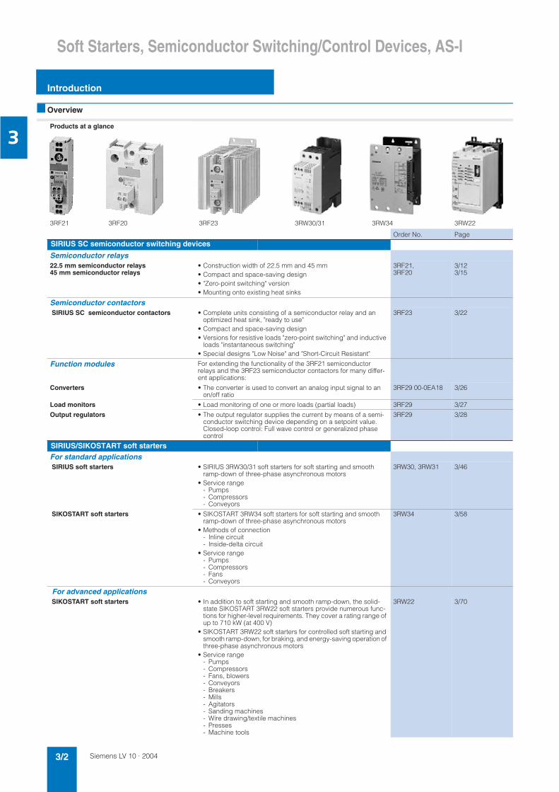
3RF21 3RF20 3RF23 3RW30/31 3RW34 3RW22
Order No. PageSIRIUS SC semiconductor switching devices
Semiconductor relays22.5 mm semiconductor relays45 mm semiconductor relays
• Construction width of 22.5 mm and 45 mm• Compact and space-saving design• "Zero-point switching" version• Mounting onto existing heat sinks
3RF21,3RF20
3/123/15
Semiconductor contactors SIRIUS SC semiconductor contactors • Complete units consisting of a semiconductor relay and an
optimized heat sink, "ready to use"• Compact and space-saving design• Versions for resistive loads "zero-point switching" and inductive
loads "instantaneous switching"• Special designs "Low Noise" and "Short-Circuit Resistant"
3RF23 3/22
Function modules For extending the functionality of the 3RF21 semiconductor relays and the 3RF23 semiconductor contactors for many differ-ent applications:
Converters • The converter is used to convert an analog input signal to an on/off ratio
3RF29 00-0EA18 3/26
Load monitors • Load monitoring of one or more loads (partial loads) 3RF29 3/27
Output regulators • The output regulator supplies the current by means of a semi-conductor switching device depending on a setpoint value.Closed-loop control: Full wave control or generalized phase control
3RF29 3/28
SIRIUS/SIKOSTART soft startersFor standard applications SIRIUS soft starters • SIRIUS 3RW30/31 soft starters for soft starting and smooth
ramp-down of three-phase asynchronous motors• Service range
- Pumps- Compressors- Conveyors
3RW30, 3RW31 3/46
SIKOSTART soft starters • SIKOSTART 3RW34 soft starters for soft starting and smooth ramp-down of three-phase asynchronous motors
• Methods of connection- Inline circuit- Inside-delta circuit
• Service range- Pumps- Compressors- Fans- Conveyors
3RW34 3/58
For advanced applications SIKOSTART soft starters • In addition to soft starting and smooth ramp-down, the solid-
state SIKOSTART 3RW22 soft starters provide numerous func-tions for higher-level requirements. They cover a rating range of up to 710 kW (at 400 V)
• SIKOSTART 3RW22 soft starters for controlled soft starting and smooth ramp-down, for braking, and energy-saving operation of three-phase asynchronous motors
• Service range - Pumps- Compressors- Fans, blowers- Conveyors- Breakers- Mills- Agitators- Sanding machines- Wire drawing/textile machines- Presses- Machine tools
3RW22 3/70

Siemens LV 10 · 2004 3/3
Soft Starters, Semiconductor Switching/Control Devices, AS-I
Introduction
3
3UF5 3UF1 8 6ED1 052 6ED1 055 6ED1 057
Order No. Page
Motor management systemsSIMOCODE-DP motor protectionand control devices
• SIMOCODE-DP comprises - Basic unit- Expansion module and - Control module
• For use in low-voltage switchgear for motor control centers of the process industry; establishes the intelligent connectionbetween the motor feeder and the process I&C system
• Increases plant availability
• Saves costs during construction, commissioning and operation of the plant
• Multifunctional, electronic motor protection and plant monitoring
• Comprehensive motor and plant diagnostics
• Integrated control programs (instead of extensive hardwarewiring)
• Open communication via PROFIBUS DP, the standard forfieldbus systems
3UF5 3/86
Current transformers for overload protection • Protection converters for activating overload relays
• Ensures proportional current transfer up to a multiple of theprimary rated current
3UF1 8 3/97
LOGO! logic modulesLOGO! logic modules • Compact, user-friendly, and low-cost solution for simple control
tasks
• Universal:- Building installation and wiring (lighting, shutters, awnings,
doors, access control, barriers, ventilation systems, etc.)- Cabinet installation- Machine and device construction (pumps, small presses,
compressors, hydraulic lifts, conveyors ...) - Special controls for conservatories and greenhouses- Signal preprocessing for other controllers
• Flexible expansion depending on the application
LOGO! Modular basic variants • With interface for connecting extension modules 6ED1 052-1 3/103
LOGO! Modular pure variants • With integrated interface for connecting extension modules 6ED1 052-2 3/104
LOGO! Modular extension modules • For connection to LOGO! Modular with digital inputs and out-puts or analog inputs
6ED1 055-1 3/106
LOGO! Modular communications modules • For communication between the LOGO! master and external EIB components via EIB.
6BK1 700-0 3/107
LOGO!Contact • Switching module for switching resistive loads and motors directly
6ED1 057-4 3/108
LOGO!Soft • Multilingual software for switching program generation for LOGO! on the PC
6ED1 058-0 3/109
AS-Interface System overview • Digital and analog signals at plant or machine level can be
transferred by AS-Interface in binary form• AS-Interface is the universal interface between the higher-level
control levels and simple binary actuators and sensors
3/110
Products at a glance

Siemens LV 10 · 20043/4
SIRIUS SC Semiconductor Switching Devices
General data
3
Overview
SIRIUS SC semiconductor switching devices• Semiconductor relays• Semiconductor contactors• Function modules
SIRIUS SC – for almost unending activity
Conventional electromechanical switching devices are often overtaxed by the rise in the number of switching operations. A high switching frequency results in frequent failure and short re-placement cycles. However, this does not have to be the case, because with the latest generation of our SIRIUS SC semicon-ductor switching devices we provide you with semiconductor re-lays and contactors with a particularly long service life – for al-most unending activity even under the toughest conditions and under high mechanical load, but also in noise-sensitive areas.
Proved time and again in service
SIRIUS SC semiconductor switching devices have become firmly established in industrial use. They are used above all in applications where loads are switched frequently – mainly with resistive load controllers, with the control of electrical heat or the control of valves and motors in conveyor systems. In addition to its use in areas with high switching frequencies, thanks to its si-lent switching SIRIUS SC is also ideally suited to noise-sensitive areas such as offices or hospitals.
The most reliable solution for any application
Compared with mechanical switching devices, our SIRIUS SC semiconductor switching devices stand out because of their considerably higher service life. Thanks to the high product quality, their switching is extremely precise, reliable and above all insusceptible to faults. With its variable connection methods and a wide spread of control voltages, the SIRIUS SC family is universally applicable. Depending on the individual require-ments of the application, our modular switching devices can also be quite easily expanded by the addition of standardized function modules.
Always on the sunny side with SIRIUS SC
Because SIRIUS SC offers even more:• The space-saving and compact side-by-side mounting ensure
reliable operation up to an ambient temperature of +60 °C.• Thanks to fast project planning and the ease of installation and
start-up you save not only time but also expense.
Function is available Function is possible
Type Semiconductor relays Semicon-ductorcontactors
Function modules
22.5 mm 45 mm Converters Load monitors Power con-trollersBasic Extended
Use
Simple use of existing semiconductor relays
Complete "Ready to use"
Space-saving
Can be extended with modular function modules
Frequent switching and monitoring of loads and semiconductor relays/semiconductor contactors
Monitoring of more than 6 partial loads
Control of the heating power via an analog input
Power control
Mounting
Mounting on standard mounting rail or mounting plate
Snapped directly onto semiconductor relay or contactor
For use with coolplate
Cable routing
Connection of load circuit as for controlgear
Connection of load circuit from above
Siemens LV 10 · 2004 3/5
SIRIUS SC Semiconductor Switching Devices
General data
3
Benefits
• Considerable space savings thanks to a width of only 22.5 mm• Variety of connection techniques: screw connection, spring-
type connection or ring terminal end, there is no problem - they are all finger-safe
• Flexible for all applications with function modules for retrofitting• Possibility of fuseless short-circuit resistant design
Advantages:• Saves time and costs with fast installation and commissioning,
short setting-up times and easy wiring• Extremely long life, low maintenance, rugged and reliable• Space-saving and safe thanks to side-by-side mounting up to
an ambient temperature of +60 °C• Modular design: standardized function modules and heat sinks
can be used in conjunction with semiconductor relays to satisfy individual requirements
• Safety due to lifelong, vibration-resistant and shock-resistant spring-loaded terminal connection system even under tough conditions
Area of application
Applications
Example plastic machine industry:
Thanks to their high switching endurance, SIRIUS SC semicon-ductor switching devices are ideally suited for use in the control of electroheat. This is because the more precise the temperature regulation process has to be, the higher the switching frequency. The accurate regulation of electroheat is used for example in many processes in the plastic machine industry:• Band heaters heat the extrudate to the correct temperature in
plastic extruders• Heat emitters heat plastic blanks to the correct temperature• Heat drums dry plastic granules• Heating channels keep molds at the correct temperature in
order to manufacture different plastic parts without defects.
The powerful SIRIUS SC semiconductor relays and contactors can be used to control several heating loads at the same time. By using a load monitoring module the individual partial loads can easily be monitored, and in the event of a failure a signal is generated to be sent to the controller.
Protecting the semiconductor relays and semiconductor contac-tors with miniature circuit-breakers (B MCB)
Short-circuit protection and line protection with miniature circuit-breakers is easy to achieve with SIRIUS SC semiconductor re-lays and semiconductor contactors in comparison with design-ing load feeders with fuses. A special version of the semicon-ductor contactors can be protected against damage in the case of a short-circuit with a miniature circuit-breaker with type B trip-ping characteristic. This allows the low-cost and simple design of fuseless load feeders with full protection of the switching de-vice.
Design
There is no typical design of a load feeder with semiconductor relays or semiconductor contactors; instead, the great variety of connection systems and control voltages offers universalapplication opportunities. SIRIUS SC semiconductor relays and semiconductor contactors can be installed in fuseless or fused feeders, as required. There are special versions with which it is even possible to achieve short-circuit strength in a fuseless design.
Functions
Connection
All SIRIUS SC semiconductor switching devices are character-ized by the great variety of connection methods. You can choose between the following connection techniques:
SIGUT connection system
The SIGUT connection system is the standard among industrial switching devices. Open terminals and a plus-minus screw are just two features of this technology. Two conductors of up to 6 mm² can be connected in just one terminal. As a result, loads of up to 50 A can be connected.
Spring-loaded connection system
This innovative technology manages without any screw connec-tion. This means that very high vibration resistance is achieved. Two conductors of up to 2.5 mm² can be connected to each ter-minal. As a result, loads of up to 20 A can be dealt with.
Ring terminal end connection
The ring terminal end connection is equipped with an M5 screw. Ring terminal ends of up to 25 mm² can be connected. In this way it is possible to connect even high powers with current in-tensities of up to 88 A safely. Finger safety is provided in this case too with a special cover.
Switching functions
In order to guarantee an optimized control method for different loads, the functionality of our semiconductor switching devices can be adapted accordingly.
The "zero-point switching" method has proved to be ideal for resistive loads, i.e. where the power semiconductor is activated at zero voltage.
For inductive loads, on the other hand, for example in the case of valves, it is better to go with "instantaneous switching". By distributing the ON point over the entire sine curve of the mains voltage, disturbances are reduced to a minimum.
Performance characteristics
The performance of the semiconductor switching devices is substantially determined by the type of power semiconductors used and the internal design. In the case of the SIRIUS SC semi-conductor contactors and semiconductor relays, only thyristors are used in place of less powerful Triacs.
Two of the most important features of thyristors are the blocking voltage and the maximum load integral:
Blocking voltage
Thyristors with a high blocking voltage can also be operated without difficulty in power systems with high interference volt-ages. Separate protective measures, such as a protective circuit with a varistor, are not necessary in most cases.
With SIRIUS SC, for example, thyristors with 800 V blocking volt-age are fitted for operation in power systems up to 230 V. Thyris-tors with up to 1600 V are used for power systems with higher voltages.
Maximum load integral
One of the purposes of specifying the maximum load integral (I²t) is to determine the rating of the short-circuit protection. Only a large power semiconductor with a correspondingly high I²tvalue can be given appropriate protection against destruction from a short-circuit by means of a protective device matched to the application. However, SIRIUS SC is also characterized by the optimum matching of the thyristors (I²t value) with the rated cur-rents. The rated currents specified on the devices in conform-ance with EN 60947-4-3 were confirmed by extensive testing. Further information is available on the Internet at:www.siemens.de/siriussc

Siemens LV 10 · 20043/6
SIRIUS SC Semiconductor Switching Devices
General data
3
Further information
Notes on integration in the load feeders
The SIRIUS SC semiconductor switching devices are very easy to integrate into the load feeders thanks to their industrial con-nection technology and design.
Particular attention must however be paid to the circumstances of the installation and ambient conditions, as the performance of the semiconductor switching devices is largely dependent on these. Depending on the version, certain restrictions must be observed. Detailed information, for example in relation to semi-conductor contactors about the minimum spacing and to semi-conductor relays about the choice of heat sink, is given in the product data sheets and the technical specifications in the A&D Mall.
Despite the rugged power semiconductors that are used, semi-conductor switching devices respond more sensitively to short-circuits in the load feeder. Consequently, special precautions have to be taken against destruction, depending on the type of design.
Siemens generally recommends using SITOR semiconductor protection fuses. These fuses also provide protection against destruction in the event of a short-circuit even when the semi-conductor contactors and semiconductor relays are fully uti-lized.
Alternatively, if there is lower loading, protection can also be pro-vided by standard fuses or miniature circuit-breakers. Thisprotection is achieved by overdimensioning the semiconductor switching devices accordingly. The technical specifications in the A&D Mall and the product data sheets contains details both about the semiconductor fuse protection itself and about use of the SIRIUS SC devices with conventional protection equipment.
The SIRIUS SC semiconductor switching devices are suitable for interference-free operation in industrial power systems without further measures. If they are used in public power systems, it may be necessary for conducted interference to be reduced by means of filters. This does not include the special type 3RF23 20-.CA.. "low noise" semiconductor contactors. These comply with the class B limit values up to a rated current of 16 A.If other versions are used, and at currents of over 16 A, standard filters can be used in order to comply with the limit values. The decisive factors when it comes to selecting the filters are essen-tially the current loading and the other parameters (operational voltage, design type, etc.) in the load feeder.
Suitable filters can be ordered from EPCOS AG (see Appendix –> External Partners).For more information go to www.epcos.com
Selection and ordering data
Accessories
1) Computer labeling system for individual labeling of item code labels avail-able from:murrplastik Systemtechnik GmbH (see Appendix –> External Partners).
Designation Labeling area/color DT Order No. PS* Weight per PU approx.
W × Hmm × mm kg
Blank identification plates
Item code labels1 frame = 20 labels
Item code labels for "SIRIUS"1)
10 × 7 pastel turquoise
D 3RT19 00-1SB10 816units
0.030
20 × 7 pastel turquoise
A 3RT19 00-1SB20 340units
0.067
"SIRIUS" labels for sticking 19 × 6 pastel turquoise
D 3RT19 00-1SB60 4700units
0.003
19 × 6 zinc yellow
C 3RT19 00-1SD60 4700units
0.003NS
K-7
237
* This quantity or a multiple thereof can be ordered.

Siemens LV 10 · 2004 3/7
SIRIUS SC Semiconductor Switching DevicesSemiconductor Relays
General data
3
Overview
Semiconductor relays
SIRIUS SC semiconductor relays are suitable for surface mount-ing on existing cooling surfaces. Installation is quick and easy, involving just two screws. The special technology of the power semiconductor ensures there is excellent thermal contact with the heat sink. Depending on the nature of the heat sink, the ca-pacity reaches up to 88 A on resistive loads. The 3RF21 semi-conductor relays can be expanded with various function mod-ules to adapt them to individual applications.
The semiconductor relays are available in 2 different widths:• 3RF21 semiconductor relay with a width of 22.5 mm• 3RF20 semiconductor relay with a width of 45 mm
Both variants are only available in the "zero-point switching" ver-sion. This standard version is ideally suited for operation with re-sistive loads.
Further information
Notes on selection
These notes are intended for general orientation and will no doubt be sufficient for most applications. If the installation con-ditions differ significantly from the examples described here, you can contact our Technical Assistance team for further help.
Telephone: +49 9131 7 43833 Fax: +49 9131 7 42899 e-mail: [email protected]
For more information on the Internet go towww.siemens.de/lowvoltage/technical-assistance
Selecting semiconductor relays
When selecting semiconductor relays, in addition to information about the power system, the load and the ambient conditions it is also necessary to know details of the planned design. The semiconductor relays can only conform to their specific techni-cal specifications if they are mounted with appropriate care on an adequately dimensioned heat sink. The following procedure is recommended:• Determine the rated current of the load and the mains voltage• Select the relay design and choose a semiconductor relay with
higher rated current than the load• Determine the thermal resistance of the proposed heat sink• Check the correct relay size with the aid of the diagrams
For more information on the Internet go towww.siemens.com/siriussc

Siemens LV 10 · 20043/8
SIRIUS SC Semiconductor Switching Devices
22.5 mm semiconductor relays
Semiconductor Relays
3
Overview
22.5 mm semiconductor relays
With its compact design, which stays the same even at currents of up to 88 A, the 3RF21 semiconductor relay is the ultimate in space-saving construction, at a width of 22.5 mm. The logical connection arrangement, with the power infeed from above and connection of the load from below, ensures tidy installation in the control cabinet.
Technical specifications
Type 3RF21 ..-1.... 3RF21 ..-2.... 3RF21 ..-3....General dataAmbient temperatureduring operation, derating from 40 °C °C -25 ... +60when stored °C -55 ... +80
Site altitude m 0 ... 1000; derating from 1000
Shock resistanceacc. to IEC 60068-2-27
g/ms 15/11
Vibration resistanceacc. to IEC 60068-2-6
g 2
Degree of protection IP20
Electromagnetic compatibility (EMC)
Emitted interference• Conducted interference voltage
acc. to IEC 60947-4-3Class A for industrial applications
• Emitted, high-frequency interference voltage acc. to IEC 60947-4-3
Class A for industrial applications
Noise immunity• Electrostatic discharge
acc. to IEC 61000-4-2 (corresponds to degree of severity 3)
kV Contact discharge 4; air discharge 8; behavior criterion 2
• Induced RF fields acc. to IEC 61000-4-6 MHz 0.15 ... 80; 140 dBµV; behavior criterion 1• Burst acc. to IEC 61000-4-4 kV 2/5.0 kHz; behavior criterion 1• Surge acc. to IEC 61000-4-5 kV Conductor - ground 2; conductor - conductor 1; behavior criterion 2
Connection technique Screw-type connection Spring-loaded connection Ring cable connection
Main contact connectionConductor cross-sectionSolid mm2 2 × (1.5 ... 2.5), 2 × (2.5 ... 6) 2 × (0,5 ... 2.5) -Finely stranded with end sleeve mm2 2 × (1.5 ... 2.5), 2 × (2.5 ... 6),
1 × 102 × (0.5 ... 1.5) -
Finely stranded without end sleeves mm2 2 × (0.5 ... 2.5) -Solid or stranded AWG conductors AWG 2 × (14 ... 10) 2 × (18 ... 14) -Insulation stripping length mm 10 10 -Terminal screw M 4 - M 5• Tightening torque Nm 2 ... 2.5 - 2 ... 2.5
lb.in 18 ... 22 - 18 ... 22Cable lug• DIN - - DIN 46234
-5-2.5, -5-6, -5-10, -5-16, -5-25• JIS - - JIS C 2805 R 2-5, 5.5-5, 8-5, 14-5
Auxiliary/control contact connectionsConductor cross-section mm2
AWG1x (0.5 ... 2.5); 2x (0.5 ... 1)20 ... 12
0.5 ... 1.520 ... 12
1x (0.5 ... 2.5); 2x (0.5 ... 1)20 ... 12
Insulation stripping length mm 7 10 7Terminal screw M 3 - M 3• Tightening torque Nm 0.5 ... 0.6 - 0.5 ... 0.6
lb.in 4.5 ... 5.3 - 4.5 ... 5.3
Type 3RF21 ..-....2 3RF21 ..-....4 3RF21 ..-....6Main circuitRated operational voltage Ue V 24 ... 230 230 ... 460 400 ... 600• Tolerance % -15 / +10• Rated frequency Hz 50/60
Rated insulation voltage Ui V 600
Blocking voltage V 800 1200 1600
Rate of voltage rise V/µs 1000
Siemens LV 10 · 2004 3/9
SIRIUS SC Semiconductor Switching DevicesSemiconductor Relays
22.5 mm semiconductor relays
3
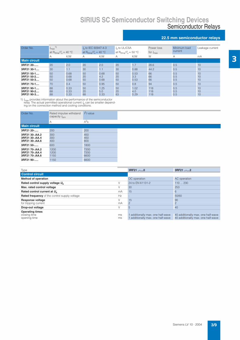
1) Imax provides information about the performance of the semiconductor relay. The actual permitted operational current Ie can be smaller depend-ing on the connection method and cooling conditions.
Order No. Imax1) Ie to IEC 60947-4-3 Ie to UL/CSA Power loss
for Imax
Minimum load current
Leakage current
at Rthha/Tu = 40 °C at Rthha/Tu = 40 °C at Rthha/Tu = 50 °C
A K/W A K/W A K/W W A mAMain circuit3RF21 20-..... 20 2.0 20 2.0 20 1.7 28.6 0.5 10
3RF21 30-1.... 30 1.1 30 1.1 30 0.88 44.2 0.5 10
3RF21 50-1.... 50 0.68 50 0.68 50 0.53 66 0.5 103RF21 50-2.... 50 0.68 20 4.2 20 3.3 66 0.5 103RF21 50-3.... 50 0.68 50 0.68 50 0.53 66 0.5 10
3RF21 70-1.... 70 0.4 50 0.95 50 0.8 94 0.5 10
3RF21 90-1.... 88 0.33 50 1.25 50 1.02 118 0.5 103RF21 90-2.... 88 0.33 20 5.0 20 4.0 118 0.5 103RF21 90-3.... 88 0.33 88 0.33 83 0.29 118 0.5 10
Order No. Rated impulse withstand capacity Itsm
I2t value
A A2sMain circuit3RF21 20-..... 200 200
3RF21 30-.AA.2 300 4503RF21 30-.AA.4 300 4503RF21 30-.AA.6 400 800
3RF21 50-..... 600 1800
3RF21 70-.AA.2 1200 72003RF21 70-.AA.4 1200 72003RF21 70-.AA.6 1150 6600
3RF21 90-..... 1150 6600
Type 3RF21 ..-....0 3RF21 ..-....2Control circuitMethod of operation DC operation AC operation
Rated control supply voltage Us V 24 to EN 61131-2 110 ... 230
Max. rated control voltage V 30 253
Rated control current at Us mA 15 6
Rated frequency of the control supply voltage Hz - 50/60
Response voltage V 15 90for tripping current mA 2 2
Drop-out voltage V 5 40
Operating timesclosing time ms 1 additionally max. one half-wave 40 additionally max. one half-waveopening time ms 1 additionally max. one half-wave 40 additionally max. one half-wave

Siemens LV 10 · 20043/10
SIRIUS SC Semiconductor Switching Devices
22.5 mm semiconductor relays
Semiconductor Relays
3
Order No. Accessories
Converters Load monitors
Basic Extended
Type current = 20 A
3RF21 2.-1..02 3RF29 00-0EA18 3RF29 20-0FA08 3RF29 20-0GA133RF21 2.-1..04 3RF29 00-0EA18 3RF29 20-0FA08 3RF29 20-0GA16
3RF21 2.-1..22 - - 3RF29 20-0GA333RF21 2.-1..24 - - 3RF29 20-0GA36
3RF21 2.-2..02 3RF29 00-0EA18 - -3RF21 2.-2..04 3RF29 00-0EA18 - -
3RF21 2.-3..02 3RF29 00-0EA18 - 3RF29 20-0GA133RF21 2.-3..04 3RF29 00-0EA18 - 3RF29 20-0GA16
3RF21 2.-3..22 - - 3RF29 20-0GA333RF21 2.-3..24 - - 3RF29 20-0GA36
Type current = 30 A
3RF21 3.-1..02 3RF29 00-0EA18 3RF29 20-0FA08 3RF29 50-0GA133RF21 3.-1..04 3RF29 00-0EA18 3RF29 20-0FA08 3RF29 50-0GA163RF21 3.-1..06 3RF29 00-0EA18 3RF29 20-0FA08 3RF29 50-0GA16
3RF21 3.-1..22 - - 3RF29 50-0GA333RF21 3.-1..24 - - 3RF29 50-0GA363RF21 3.-1..26 - - 3RF29 50-0GA36
Type current = 50 A
3RF21 5.-1..02 3RF29 00-0EA18 3RF29 20-0FA08 3RF29 50-0GA133RF21 5.-1..04 3RF29 00-0EA18 3RF29 20-0FA08 3RF29 50-0GA163RF21 5.-1..06 3RF29 00-0EA18 3RF29 20-0FA08 3RF29 50-0GA16
3RF21 5.-1..22 - - 3RF29 50-0GA333RF21 5.-1..24 - - 3RF29 50-0GA363RF21 5.-1..26 - - 3RF29 50-0GA36
3RF21 5.-2..02 3RF29 00-0EA18 - -3RF21 5.-2..04 3RF29 00-0EA18 - -3RF21 5.-2..06 3RF29 00-0EA18 - -
3RF21 5.-3..02 3RF29 00-0EA18 - 3RF29 50-0GA133RF21 5.-3..06 3RF29 00-0EA18 - 3RF29 50-0GA163RF21 5.-3..04 3RF29 00-0EA18 - 3RF29 50-0GA16
3RF21 5.-3..22 - - 3RF29 50-0GA333RF21 5.-3..24 - - 3RF29 50-0GA363RF21 5.-3..26 - - 3RF29 50-0GA36
Type current = 70 A
3RF21 7.-1..02 3RF29 00-0EA18 3RF29 20-0FA08 3RF29 90-0GA133RF21 7.-1..04 3RF29 00-0EA18 3RF29 20-0FA08 3RF29 90-0GA163RF21 7.-1..06 3RF29 00-0EA18 3RF29 20-0FA08 3RF29 90-0GA16
3RF21 7.-1..22 - - 3RF29 90-0GA333RF21 7.-1..24 - - 3RF29 90-0GA363RF21 7.-1..26 - - 3RF29 90-0GA36
Type current = 90 A
3RF21 9.-1..02 3RF29 00-0EA18 3RF29 20-0FA08 3RF29 90-0GA133RF21 9.-1..04 3RF29 00-0EA18 3RF29 20-0FA08 3RF29 90-0GA163RF21 9.-1..06 3RF29 00-0EA18 3RF29 20-0FA08 3RF29 90-0GA16
3RF21 9.-1..22 - - 3RF29 90-0GA333RF21 9.-1..24 - - 3RF29 90-0GA363RF21 9.-1..26 - - 3RF29 90-0GA36
3RF21 9.-2..02 3RF29 00-0EA18 - -3RF21 9.-2..06 3RF29 00-0EA18 - -3RF21 9.-2..04 3RF29 00-0EA18 - -
3RF21 9.-3..02 3RF29 00-0EA18 - 3RF29 90-0GA133RF21 9.-3..04 3RF29 00-0EA18 - 3RF29 90-0GA163RF21 9.-3..06 3RF29 00-0EA18 - 3RF29 90-0GA16
3RF21 9.-3..22 - - 3RF29 90-0GA333RF21 9.-3..26 - - 3RF29 90-0GA363RF21 9.-3..24 - - 3RF29 90-0GA36

Siemens LV 10 · 2004 3/11
SIRIUS SC Semiconductor Switching DevicesSemiconductor Relays
22.5 mm semiconductor relays
3
Fused design with semiconductor protection (similar to type of coordination "2")1)
The semiconductor protection for the SIRIUS SC controlgear can be implemented with different protective devices. This allows protection by means of LV HRC fuses of operational class gL/gG or miniature circuit-breakers. Siemens recommends the use of special SITOR semiconductor fuses. The table below lists the maximum permissible fuses for each SIRIUS SC controlgear.
If a fuse is used with a higher rated current than specified, semi-conductor protection is no longer guaranteed. However, smaller fuses with a lower rated current for the load can be used without problems. For protective devices with operational class gL/gG and for 3NE1 SITOR full range fuses, the minimum cross-sections for the conductors to be protected must be taken into account.
1) Type of coordination "2" acc. to EN 60947-4-1:In the event of a short-circuit, the controlgear in the load feeder must not endanger persons or the installation. They must be suitable for further operation. For fused configurations, the protective device must be replaced.
2) These versions can also be protected against short-circuit with miniature circuit-breakers as described on page 3/16.
Order No. All-range fuse LV design gR/SITOR3NE1
Semiconductor protection fuse Cylindrical design
Cable and line protection fuse
LV design gL/gG/3NA
Cylindrical design DIAZED quick5SB10 × 38 mm
gL/gG/3NW14 × 51 mmgL/gG/3NW
22 × 58 mmgL/gG/3NW
10 × 38 mmaR/SITOR3NC1 0
14 × 51 mmaR/SITOR3NC1 4
22 × 58 mmaR/SITOR3NC2 2
3RF21 2.-....2 3NE1 814-0 3NC1 020 3NC1 420 3NC2 220 3NA2 803 3NW6 001-1 3NW6 101-1 - 5SB1 713RF21 2.-....4 3NE1 813-0 3NC1 016 3NC1 420 3NC2 220 3NA2 801 - 3NW6 101-1 - 5SB1 41
3RF21 3.-....2 3NE1 815-0 3NC1 032 3NC1 432 3NC2 232 3NA2 803 - 3NW6 103-1 - 5SB3 113RF21 3.-....4 3NE1 815-0 3NC1 025 3NC1 432 3NC2 232 3NA2 803 - 3NW6 101-1 - 5SB1 713RF21 3.-....6 3NE1 815-0 3NC1 032 3NC1 432 3NC2 232 3NA2 803-6 - - - -
3RF21 5.-....2 3NE1 817-0 - 3NC1 450 3NC2 250 3NA2 810 - 3NW6 107-1 3NW6 207-1 5SB3 213RF21 5.-....4 3NE1 802-0 - 3NC1 450 3NC2 250 3NA2 807 - - 3NW6 205-1 5SB3 113RF21 5.-....6 3NE1 803-0 - 3NC1 450 3NC2 250 3NA2 807-6 - - - -
3RF21 7.-....22) 3NE1 820-0 - - 3NC2 280 3NA2 817 - - 3NW6 217-1 5SB3 313RF21 7.-....42) 3NE1 020-2 - - 3NC2 280 3NA2 812 - - 3NW6 212-1 5SB3 213RF21 7.-....62) 3NE1 020-2 - - 3NC2 280 3NA2 812-6 - - - -
3RF21 9.-....22) 3NE1 021-2 - - 3NC2 200 3NA2 817 - - 3NW6 217-1 5SB3 313RF21 9.-....42) 3NE1 021-2 - - 3NC2 280 3NA2 812 - - 3NW5 212-1 5SB3 213RF21 9.-....62) 3NE1 020-2 - - 3NC2 280 3NA2 812-6 - - - -

Siemens LV 10 · 20043/12
SIRIUS SC Semiconductor Switching Devices
22.5 mm semiconductor relays
Semiconductor Relays
3
Selection and ordering data
Other rated control supply voltages on request.1) The type current provides information about the performance of the semi-
conductor relay. The actual permitted operational current Ie can be smaller depending on the connection method and cooling conditions.
2) Please note that this version can only be used for a rated current of up to 50 A and a conductor cross-section of 10 mm2.
3) Please note that this version can only be used for a rated current of up to 20 A and a conductor cross-section of 2.5 mm2.
3RF21 20-1AA02 3RF21 20-2AA02 3RF21 20-3AA02
Type current1)
Maximum achiev-able power for type current and Ue =
DT Screw connection 2)
PS* Weight per PU approx.
DT Spring-loadedconnection 3)
PS* Weight per PU approx.
DT Ring cable connection
PS* Weight per PU approx.
115 V 230 V 400 V
A kW kW kW Order No. kg Order No. kg Order No. kgZero-point switching, rated operational voltage Ue = 24 V to 230 V20 2.3 4.6 - A 3RF21 20-1AA@2 1 unit 0.052 B 3RF21 20-2AA@2 1 unit 0.052 B 3RF21 20-3AA@2 1 unit 0.05230 3.5 6.9 - A 3RF21 30-1AA@2 1 unit 0.052 - -50 5.8 11.5 - A 3RF21 50-1AA@2 1 unit 0.052 B 3RF21 50-2AA@2 1 unit 0.052 B 3RF21 50-3AA@2 1 unit 0.05270 8.1 16.1 - A 3RF21 70-1AA@2 1 unit 0.052 - -88 10.4 20.7 - A 3RF21 90-1AA@2 1 unit 0.052 B 3RF21 90-2AA@2 1 unit 0.052 B 3RF21 90-3AA@2 1 unit 0.052Zero-point switching, rated operational voltage Ue = 230 V to 460 V20 - 4.6 8 A 3RF21 20-1AA@4 1 unit 0.052 B 3RF21 20-2AA@4 1 unit 0.052 B 3RF21 20-3AA@4 1 unit 0.05230 - 6.9 12 A 3RF21 30-1AA@4 1 unit 0.052 - -50 - 11.5 20 A 3RF21 50-1AA@4 1 unit 0.052 B 3RF21 50-2AA@4 1 unit 0.052 B 3RF21 50-3AA@4 1 unit 0.05270 - 16.1 28 A 3RF21 70-1AA@4 1 unit 0.052 - -88 - 20.7 36 A 3RF21 90-1AA@4 1 unit 0.052 B 3RF21 90-2AA@4 1 unit 0.052 B 3RF21 90-3AA@4 1 unit 0.052Zero-point switching, rated operational voltage Ue = 400 V to 600 V30 - - 12 B 3RF21 30-1AA@6 1 unit 0.052 - -
50 - - 20 B 3RF21 50-1AA@6 1 unit 0.052 B 3RF21 50-2AA@6 1 unit 0.052 B 3RF21 50-3AA@6 1 unit 0.05270 - - 28 B 3RF21 70-1AA@6 1 unit 0.052 - -88 - - 36 B 3RF21 90-1AA@6 1 unit 0.052 B 3RF21 90-2AA@6 1 unit 0.052 B 3RF21 90-3AA@6 1 unit 0.052
Order No. extension for rated control supply voltage Us
DC 24 V acc. to EN 61131-2 0 0 0AC 110 V ... 230 V 2 2 2
Version DT Order No. PS* Weight per PU approx.
kgAccessories
Screwdriver for spring-loaded connection system A 8WA2 880 1 unit 0.034
3RF29 00-3PA88
Terminal cover for 3RF21 semiconductor relays and 3RF23 semiconductor contactors with ring terminal end (after simple adaptation, this terminal cover can also be used for screw connection).
A 3RF29 00-3PA88 10units
0.010
* This quantity or a multiple thereof can be ordered.

Siemens LV 10 · 2004 3/13
SIRIUS SC Semiconductor Switching DevicesSemiconductor Relays
45 mm semiconductor relays
3
Overview
45 mm semiconductor relays
The semiconductor relays with a width of 45 mm provide for con-nection of the power supply lead and the load from above. This makes it easy to replace existing semiconductor relays in exist-ing arrangements. The connection of the control cable also saves space in much the same way as the 22.5 mm design, as it is simply plugged on.
Technical specifications
Type 3RF20General dataAmbient temperatureduring operation, derating at 40 °C °C -25 ... +60when stored °C -55 ... +80
Site altitude m 0 ... 1000; derating from 1000
Shock resistanceacc. to IEC 60068-2-27
g/ms 15/11
Vibration resistanceacc. to IEC 60068-2-6
g 2
Degree of protection IP20
Electromagnetic compatibility (EMC)Emitted interference• Conducted interference voltage IEC
acc. to 60947-4-3Class A for industrial applications
• Emitted, high-frequency interference voltage acc. to IEC 60947-4-3
Class A for industrial applications
Noise immunity• Electrostatic discharge
acc. to IEC 61000-4-2 (corresponds to degree of severity 3)
kV Contact discharge 4; air discharge 8; behavior criterion 2
• Induced RF fields acc. to IEC 61000-4-6 MHz 0.15 ... 80; 140 dBµV; behavior criterion 1• Burst acc. to IEC 61000-4-4 kV 2/5.0 kHz; behavior criterion 1• Surge acc. to IEC 61000-4-5 kV Conductor - ground 2; conductor - conductor 1; behavior criterion 2
Connection, main contacts, screw con-nectionConductor cross-sectionSolid mm2 2 × (1.5 ... 2.5); 2 × (2.5 ... 6)Finely stranded with end sleeve mm2 2 × (1.5 ... 2.5); 2 × (2.5 ... 6); 1 × 10Solid or stranded AWG conductors AWG 2 × (14 ... 10)Insulation stripping length mm 10Terminal screw M 4• Tightening torque Nm 2 ... 2.5
lb.in 18 ... 22
Connection, auxiliary/control contacts,screw connectionConductor cross-section mm2 1x (0.5 ... 2.5); 2x (0.5 ... 1.0); AWG 20 ... 12Insulation stripping length mm 7Terminal screw M 3• Tightening torque Nm 0.5 ... 0.6
lb.in 4.5 ... 5.3
Type 3RF20 .0-1AA.2 3RF20 .0-1AA.4 3RF20 .0-1AA.6Main circuitRated operational voltage Ue V 24 ... 230 230 ... 460 400 ... 600• Tolerance % -15/+10• Rated frequency Hz 50/60
Rated insulation voltage Ui V 600
Blocking voltage V 800 1200 1600
Rage of voltage rise V/µs 1000
Siemens LV 10 · 20043/14
SIRIUS SC Semiconductor Switching Devices
45 mm semiconductor relays
Semiconductor Relays
3
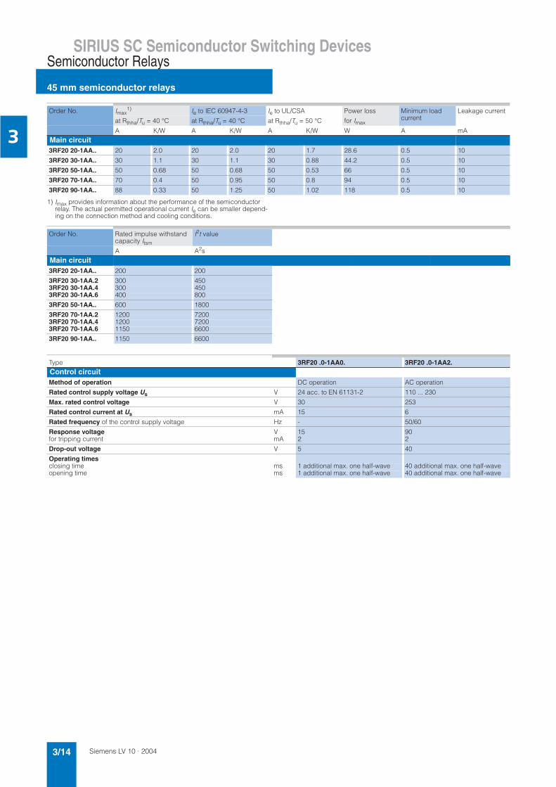
1) Imax provides information about the performance of the semiconductor relay. The actual permitted operational current Ie can be smaller depend-ing on the connection method and cooling conditions.
Order No. Imax1) Ie to IEC 60947-4-3 Ie to UL/CSA Power loss
for Imax
Minimum load current
Leakage current
at Rthha/Tu = 40 °C at Rthha/Tu = 40 °C at Rthha/Tu = 50 °C
A K/W A K/W A K/W W A mAMain circuit3RF20 20-1AA.. 20 2.0 20 2.0 20 1.7 28.6 0.5 10
3RF20 30-1AA.. 30 1.1 30 1.1 30 0.88 44.2 0.5 10
3RF20 50-1AA.. 50 0.68 50 0.68 50 0.53 66 0.5 10
3RF20 70-1AA.. 70 0.4 50 0.95 50 0.8 94 0.5 10
3RF20 90-1AA.. 88 0.33 50 1.25 50 1.02 118 0.5 10
Order No. Rated impulse withstand capacity Itsm
I2t value
A A2sMain circuit3RF20 20-1AA.. 200 200
3RF20 30-1AA.2 300 4503RF20 30-1AA.4 300 4503RF20 30-1AA.6 400 800
3RF20 50-1AA.. 600 1800
3RF20 70-1AA.2 1200 72003RF20 70-1AA.4 1200 72003RF20 70-1AA.6 1150 6600
3RF20 90-1AA.. 1150 6600
Type 3RF20 .0-1AA0. 3RF20 .0-1AA2.Control circuitMethod of operation DC operation AC operation
Rated control supply voltage Us V 24 acc. to EN 61131-2 110 ... 230
Max. rated control voltage V 30 253
Rated control current at Us mA 15 6
Rated frequency of the control supply voltage Hz - 50/60
Response voltage V 15 90for tripping current mA 2 2
Drop-out voltage V 5 40
Operating timesclosing time ms 1 additional max. one half-wave 40 additional max. one half-waveopening time ms 1 additional max. one half-wave 40 additional max. one half-wave

Siemens LV 10 · 2004 3/15
SIRIUS SC Semiconductor Switching DevicesSemiconductor Relays
45 mm semiconductor relays
3
Fused design with semiconductor protection(similar to type of coordination "2")1)
The semiconductor protection for the SIRIUS SC control gear can be used with different protective devices. This allowsprotection by means of LV HRC fuses of operational class gL/gG or miniature circuit-breakers. Siemens recommends the use of special SITOR semiconductor fuses. The table below lists the maximum permissible fuses for each SIRIUS SC controlgear.
If a fuse is used with a higher rated current than specified, semi-conductor protection is no longer guaranteed. However, smaller fuses with a lower rated current for the load can be used without problems. For protective devices with operational class gL/gG and for SITOR full range fuses 3NE1, the minimum cross-sections for the conductor to be connected must be taken into account.
1) Type of coordination "2" acc. to EN 60947-4-1:In the event of a short-circuit, the control gear in the load feeder must not endanger persons or the installation. They must be suitable for further operation. For fused configurations, the protective device must be replaced.
2) These versions can also be protected against short-circuit with miniature circuit-breakers as described on page 3/16.
Selection and ordering data
Other rated control supply voltages on request.1) The type current provides information about the performance of the semi-
conductor relay. The actual permitted operational current Ie can be smaller depending on the connection method and cooling conditions.
2) Please note that this version can only be used for a rated current of up to 50 A and a conductor cross-section of 10 mm2.
Order No. All-range fuse LV design gR/SITOR3NE1
Semiconductor protection fuse Cylindrical design
Cable and line protection fuse
LV design gL/gG/3NA
Cylindrical design DIAZED quick 5SB10 × 38 mm
gL/gG 3NW14 × 51 mm gL/gG 3NW
22 × 58 mm gL/gG 3NW
10 × 38 mm aR/SITOR3NC1 0
14 × 51 mm aR/SITOR3NC1 4
22 × 58 mm aR/SITOR3NC2 2
3RF20 20-1AA.2 3NE1 814-0 3NC1 020 3NC1 420 3NC2 220 3NA2 803 3NW6 001-1 3NW6 101-1 - 5SB1 713RF20 20-1AA.4 3NE1 813-0 3NC1 016 3NC1 420 3NC2 220 3NA2 801 - 3NW6 101-1 - 5SB1 41
3RF20 30-1AA.2 3NE1 815-0 3NC1 032 3NC1 432 3NC2 232 3NA2 803 - 3NW6 103-1 - 5SB3 113RF20 30-1AA.4 3NE1 815-0 3NC1 025 3NC1 432 3NC2 232 3NA2 803 - 3NW6 101-1 - 5SB1 713RF20 30-1AA.6 3NE1 815-0 3NC1 032 3NC1 432 3NC2 232 3NA2 803-6 - - - -
3RF20 50-1AA.2 3NE1 817-0 - 3NC1 450 3NC2 250 3NA2 810 - 3NW6 107-1 3NW6 207-1 5SB3 213RF20 50-1AA.4 3NE1 802-0 - 3NC1 450 3NC2 250 3NA2 807 - - 3NW6 205-1 5SB3 113RF20 50-1AA.6 3NE1 803-0 - 3NC1 450 3NC2 250 3NA2 807-6 - - - -
3RF20 70-1AA.22) 3NE1 820-0 - - 3NC2 280 3NA2 817 - - 3NW6 217-1 5SB3 313RF20 70-1AA.42) 3NE1 020-2 - - 3NC2 280 3NA2 812 - - 3NW6 212-1 5SB3 213RF20 70-1AA.62) 3NE1 020-2 - - 3NC2 280 3NA2 812-6 - - - -
3RF20 90-1AA.22) 3NE1 021-2 - - 3NC2 200 3NA2 817 - - 3NW6 217-1 5SB3 313RF20 90-1AA.42) 3NE1 021-2 - - 3NC2 280 3NA2 812 - - 3NW6 212-1 5SB3 213RF20 90-1AA.62) 3NE1 020-2 - - 3NC2 280 3NA2 812-6 - - - -
Type current1) Maximum achievable power for type current and Ue = DT Order No.2) PS* Weight per PU approx.
115 V 230 V 400 V
A kW kW kW kgZero-point switching, rated operational voltage Ue = 24 V to 230 V
3RF20 20-1AA02
20 2.3 4.6 - A 3RF20 20-1AA@2 1 unit 0.06230 3.5 6.9 - A 3RF20 30-1AA@2 1 unit 0.06250 5.8 11.5 - A 3RF20 50-1AA@2 1 unit 0.06270 8.1 16.1 - A 3RF20 70-1AA@2 1 unit 0.06288 10.4 20.7 - A 3RF20 90-1AA@2 1 unit 0.062
Zero-point switching, rated operational voltage Ue = 230 V to 460 V20 - 4.6 8 A 3RF20 20-1AA@4 1 unit 0.06230 - 6.9 12 A 3RF20 30-1AA@4 1 unit 0.06250 - 11.5 20 A 3RF20 50-1AA@4 1 unit 0.06270 - 16.1 28 A 3RF20 70-1AA@4 1 unit 0.06288 - 20.7 36 A 3RF20 90-1AA@4 1 unit 0.062
Zero-point switching, rated operational voltage Ue = 400 V to 600 V30 - - 12 B 3RF20 30-1AA@6 1 unit 0.06250 - - 20 B 3RF20 50-1AA@6 1 unit 0.06270 - - 28 B 3RF20 70-1AA@6 1 unit 0.06288 - - 36 B 3RF20 90-1AA@6 1 unit 0.062
Order No. extension for rated control supply voltage Us
DC 24 V acc. to EN 61131-2 0AC 110 V ... 230 V 2
*This quantity or a multiple thereof can be ordered.

Siemens LV 10 · 20043/16
SIRIUS SC Semiconductor Switching Devices
SIRIUS SC semiconductor contactors
Semiconductor Contactors
3
Overview
The complete self-contained units consist of a semiconductor relay plus optimized heat sink, and are therefore ready to use. They offer defined rated currents to make selection as easy as possible. Depending on the version, current intensities of up to 88 A are achieved. Like all of our semiconductor switching de-vices, one of their particular advantages is their compact and space-saving design. With their insulated mounting foot they can easily be snapped onto a standard mounting rail, or they can be mounted on carrier plates with fixing screws. This insula-tion enables them to be used in circuits with protective extra-low voltage (PELV) or safety extra-low voltage (SELV) in building en-gineering. For other applications, such as for extended personal safety, the heat sink can be grounded through a screw connec-tion.
Version for resistive loads, "zero-point switching"
This standard version is often used for switching space heaters on and off.
Version for inductive loads, "instantaneous switching"
In this version the semiconductor contactor is specifically matched to inductive loads. Whether it is a matter of frequent ac-tuation of the valves in a filling plant or starting and stopping small drives in packet distribution systems, operation is carried out safely and noiselessly.
Special "low noise" version
Thanks to a special control circuit, this special design can be used in public networks up to 16 A without any additional mea-sures such as interference suppressor filters. As a result it con-forms to limit value curve class B in accordance with EN 60947-4-3 in terms of emitted interference.
Special "short-circuit" version
Skilful matching of the power semiconductor with the perfor-mance of the semiconductor contactor means that "short-circuit strength" can be achieved with a standard miniature circuit-breaker. In combination with a B-type MCB or a conventional fuse, the result is a short-circuit resistant feeder.
In order to achieve problem-free short-circuit protection by means of miniature circuit-breakers, however, certain boundary conditions must be observed. As the magnitude and duration of the short-circuit current are determined not only by theshort-circuit breaking response of the miniature circuit-breaker but also the properties of the wiring system, such as the internal
resistance of the input to the network and damping by switching devices and cables, particular attention must also be paid to these parameters. The necessary cable lengths are therefore shown for the main factor, the conductor resistance, in the table below.
The following miniature circuit-breakers with a B characteristic and 10 kA breaking capacity protect the 3RF2320-.DA.. semi-conductor contactors in the event of short-circuits on the load and the specified conductor cross-sections and lengths:
The setup and installation above can also be used for the semiconductor relays with a I2t value of at least 6600 A2s.
Technical specifications
Rated current of miniature circuit- breakers
Exampleof type
Max. conductorcross-section
Min. cable length from contactor to load
6 A 5SY4 106-6 1 mm² 5 m
10 A 5SY4 110-6 1.5 mm² 8 m
16 A 5SY4 116-6 1.5 mm² 12 m
16 A 5SY4 116-6 2.5 mm² 20 m
20 A 5SY4 120-6 2.5 mm² 20 m
!
"
!
"
#
"
"
!
"
#
$%
!&&'("!&
$%
!&&'("!&
$%
Order No. 3RF23 ..-.A... 3RF23 ..-.B... 3RF23 ..-.C... 3RF23 ..-.D...General dataAmbient temperatureduring operation, derating at 40 °C °C -25 ... +60when stored °C -55 ... +80
Site altitude m 0 ... 1000; derating from 1000
Shock resistance acc. to IEC 60068-2-27 g/ms 15/11
Vibration resistance acc. to IEC 60068-2-6 g 2
Degree of protection IP20
Electromagnetic compatibility (EMC)
Emitted interference acc. to IEC 60947-4-3
• Conducted interference voltage• Emitted high-frequency interference voltage
Class A for industrial applications Class A for industrialapplications;Class B for resi-dential/business/commercial areas up to 16 A, AC51 Low Noise
Class A for industrialapplications
Noise immunity• Electrostatic discharge acc. to IEC 61000-4-2
(corresponds to degree of severity 3)kV Contact discharge 4; air discharge 8; behavior criterion 2
• Induced RF fields acc. to IEC 61000-4-6 MHz 0.15 ... 80; 140 dBµV; behavior criterion 1• Burst acc. to IEC 61000-4-4 kV 2/5.0 kHz; behavior criterion 1• Surge acc. to IEC 61000-4-5 kV Conductor - ground 2; conductor - conductor 1; behavior criterion 2

Siemens LV 10 · 2004 3/17
SIRIUS SC Semiconductor Switching DevicesSemiconductor Contactors
SIRIUS SC semiconductor contactors
3
1) The type current provides information about the performance of the semi-conductor contactor. The actual permitted operational current Ie can be smaller depending on the connection method and start-up conditions.Derating acc. to curves from page 3/30!
Order No. 3RF23 ..-1.... 3RF23 ..-2.... 3RF23 ..-3....General dataConnection technique Screw connection Spring-loaded connection Ring cable connection
Main contact connectionConductor cross-sectionSolid mm2 2 × (1.5 ... 2.5), 2 × (2.5 ... 6) 2 × (0.5 ... 2.5) -Finely stranded with end sleeve mm2 2 × (1.5 ... 2.5), 2 × (2.5 ... 6), 1 × 10 2 × (0.5 ... 1.5) -Finely stranded without end sleeves mm2 2 × (0.5 ... 2.5) -Solid or stranded AWG conductors AWG 2 × (14 ... 10) 2 × (18 ... 14) -Insulation stripping length mm 10 10 -Terminal screw M 4 - M 5• Tightening torque Nm 2 ... 2.5 - 2 ... 2.5• Tightening torque lb.in 18 ... 22 - 18 ... 22Cable lug• DIN - - DIN 46234
-5-2.5, -5-6, -5-10, -5-16, -5-25• JIS - - JIS C 2805 R 2-5, 5.5-5, 8-5, 14-5
Auxiliary/control contactconnectionsConductor cross-section mm2
AWG1x (0.5 ... 2.5); 2x (0.5 ... 1.0)20 ... 12
0.5 ... 1.520 ... 12
1x (0.5 ... 2.5); 2x (0.5 ... 1.0)20 ... 12
Insulation stripping length mm 7 10 7Terminal screw M 3 - M 3• Tightening torque Nm 0.5 ... 0.6 - 0.5 ... 0.6
lb.in 4.5 ... 5.3 - 4.5 ... 5.3
Type 3RF23 ..-....2 3RF23 ..-....4 3RF23 ..-....6Main circuitRated operational voltage Ue V 24 ... 230 230 ... 460 400 ... 600• Tolerance % -15/+10• Rated frequency Hz 50/60 Hz
Rated insulation voltage Ui V 600
Blocking voltage V 800 1200 1600
Rate of voltage rise V/µs 1000
Order No. Type current AC-511) Power loss at Imax
Minimum load current
Leakagecurrent
Rated impulse withstandcapacity Itsm
I2t value
Imax
at 40 °C
acc. to IEC 60947-4-3 at 40 °C
UL/CSA
at 50 °C
A A A W A mA A A2sMain circuit3RF23 1.-.A..2 10.5 7.5 9.6 11 0.5 10 200 2003RF23 1.-.A..4 200 2003RF23 1.-.A..6 400 800
3RF23 2.-.A..2 20 13.2 17.6 20 0.5 10 600 18003RF23 2.-.C..2 25 600 18003RF23 2.-.D..2 10 1150 6600
3RF23 2.-.A..4 10 600 18003RF23 2.-.C..4 25 600 18003RF23 2.-.D..4 10 1150 6600
3RF23 2.-.A..6 10 600 1800
3RF23 3.-.A..2 30 22 27 33 0.5 10 600 18003RF23 3.-.A..43RF23 3.-.A..6
3RF23 4.-.A..2 40 33 36 44 0.5 10 1200 72003RF23 4.-.A..4 1200 72003RF23 4.-.A..6 1150 6600
3RF23 5.-.A..2 50 36 45 54 0.5 10 1150 66003RF23 5.-.A..43RF23 5.-.A..6
3RF23 7.-.A..2 70 70 62 83 0.5 10 1150 66003RF23 7.-.A..43RF23 7.-.A..6
3RF23 9.-.A..2 88 88 80 117 0.5 10 1150 66003RF23 9.-.A..43RF23 9.-.A..6

Siemens LV 10 · 20043/18
SIRIUS SC Semiconductor Switching Devices
SIRIUS SC semiconductor contactors
Semiconductor Contactors
3
1) The type current provides information about the performance of the semi-conductor contactor. The actual permitted operational current Ie can be smaller depending on the connection method and start-up conditions.Derating acc. to curves from page 3/30!
Order No. Type current AC-511) Power loss at Imax
Minimumload current
Leakagecurrent
Rated impulse withstand capacity Itsm
I2t value
Imax
at 40 °C
acc. to IEC 60947-4-3at 40 °C
UL/CSA
at 50 °C
AC-15
Parameters
A A A A W A mA A A2sMain circuit3RF23 1.-.B..2 10.5 7.5 9.6 6 1200 1/h
50 % ED11 0.5 10 200 200
3RF23 1.-.B..4 200 2003RF23 1.-.B..6 400 800
3RF23 2.-.B..2 20 13.2 17.6 12 1200 1/h 50 % ED
20 0.5 10 600 18003RF23 2.-.B..43RF23 2.-.B..6
3RF23 3.-.B..2 30 22 27 15 1200 1/h 50 % ED
33 0.5 10 600 18003RF23 3.-.B..43RF23 3.-.B..6
3RF23 4.-.B..2 40 33 36 20 1200 1/h 50 % ED
44 0.5 10 1200 72003RF23 4.-.B..4 1200 72003RF23 4.-.B..6 1150 6600
3RF23 5.-.B..2 50 36 45 25 1200 1/h 50 % ED
54 0.5 10 1150 66003RF23 5.-.B..43RF23 5.-.B..6
3RF23 7.-.B..2 70 70 62 27.5 1200 1/h 50 % ED
83 0.5 10 1150 66003RF23 7.-.B..43RF23 7.-.B..6
3RF23 9.-.B..2 88 88 80 30 1200 1/h 50 % ED
117 0.5 10 1150 66003RF23 9.-.B..43RF23 9.-.B..6
Type 3RF23 ..-...0. 3RF23 ..-...2.Control circuitMethod of operation DC operation AC operation
Rated control supply voltage Us V 24 to EN 61131-2 110 ... 230
Max. rated control voltage V 30 253
Rated control current at Us mA 15 6
Rated frequency of the control supply voltage Hz 50/60
Response voltage V 15 90for tripping current mA 2 2
Drop-out voltage V 5 40
Operating timesclosing time ms 1 additional max. one half-wave 40 additional max. one half-waveopening time ms 1 additional max. one half-wave 40 additional max. one half-wave

Siemens LV 10 · 2004 3/19
SIRIUS SC Semiconductor Switching DevicesSemiconductor Contactors
SIRIUS SC semiconductor contactors
3
Order No. Accessories
Converters Load monitors Power controllers
Basic Extended
Type current = 10.5 A
3RF23 1.-1A.02 3RF29 00-0EA18 3RF29 20-0FA08 3RF29 20-0GA13 -3RF23 1.-1A.04 3RF29 00-0EA18 3RF29 20-0FA08 3RF29 20-0GA16 -3RF23 1.-1A.06 3RF29 00-0EA18 3RF29 20-0FA08 3RF29 20-0GA16 -
3RF23 1.-1A.22 - - 3RF29 20-0GA33 -3RF23 1.-1A.24 - - 3RF29 20-0GA36 -3RF23 1.-1A.26 - - 3RF29 20-0GA36 -
3RF23 1.-1B.02 3RF29 00-0EA18 3RF29 20-0FA08 3RF29 20-0GA13 3RF29 20-0HA133RF23 1.-1B.04 3RF29 00-0EA18 3RF29 20-0FA08 3RF29 20-0GA16 3RF29 20-0HA163RF23 1.-1B.06 3RF29 00-0EA18 3RF29 20-0FA08 3RF29 20-0GA16 3RF29 20-0HA16
3RF23 1.-1B.22 - - 3RF29 20-0GA33 3RF29 20-0HA333RF23 1.-1B.24 - - 3RF29 20-0GA36 3RF29 20-0HA363RF23 1.-1B.26 - - 3RF29 20-0GA36 3RF29 20-0HA36
3RF23 1.-2A.02 3RF29 00-0EA18 - - -3RF23 1.-2A.04 3RF29 00-0EA18 - - -3RF23 1.-2A.06 3RF29 00-0EA18 - - -
3RF23 1.-2A.22 - - - -3RF23 1.-2A.24 - - - -3RF23 1.-2A.26 - - - -
3RF23 1.-3A.02 3RF29 00-0EA18 - 3RF29 20-0GA13 -3RF23 1.-3A.04 3RF29 00-0EA18 - 3RF29 20-0GA16 -3RF23 1.-3A.06 3RF29 00-0EA18 - 3RF29 20-0GA16 -
3RF23 1.-3A.22 - - 3RF29 20-0GA33 -3RF23 1.-3A.24 - - 3RF29 20-0GA36 -3RF23 1.-3A.26 - - 3RF29 20-0GA36 -
Type current = 20 A
3RF23 2.-1A.02 3RF29 00-0EA18 3RF29 20-0FA08 3RF29 20-0GA13 -3RF23 2.-1A.04 3RF29 00-0EA18 3RF29 20-0FA08 3RF29 20-0GA16 -3RF23 2.-1A.06 3RF29 00-0EA18 3RF29 20-0FA08 3RF29 20-0GA16 -
3RF23 2.-1A.22 - - 3RF29 20-0GA33 -3RF23 2.-1A.24 - - 3RF29 20-0GA36 -3RF23 2.-1A.26 - - 3RF29 20-0GA36 -
3RF23 2.-1B.02 3RF29 00-0EA18 3RF29 20-0FA08 3RF29 20-0GA13 3RF29 20-0HA133RF23 2.-1B.04 3RF29 00-0EA18 3RF29 20-0FA08 3RF29 20-0GA16 3RF29 20-0HA163RF23 2.-1B.06 3RF29 00-0EA18 3RF29 20-0FA08 3RF29 20-0GA16 3RF29 20-0HA16
3RF23 2.-1B.22 - - 3RF29 20-0GA33 3RF29 20-0HA333RF23 2.-1B.24 - - 3RF29 20-0GA36 3RF29 20-0HA363RF23 2.-1B.26 - - 3RF29 20-0GA36 3RF29 20-0HA36
3RF23 2.-1C.02 3RF29 00-0EA18 3RF29 20-0FA08 3RF29 20-0GA13 -3RF23 2.-1C.04 3RF29 00-0EA18 3RF29 20-0FA08 3RF29 20-0GA16 -
3RF23 2.-1C.22 - - 3RF29 20-0GA33 -3RF23 2.-1C.24 - - 3RF29 20-0GA36 -
3RF23 2.-1D.02 3RF29 00-0EA18 3RF29 20-0FA08 3RF29 20-0GA13 -3RF23 2.-1D.04 3RF29 00-0EA18 3RF29 20-0FA08 3RF29 20-0GA16 -
3RF23 2.-1D.22 - - 3RF29 20-0GA33 -3RF23 2.-1D.24 - - 3RF29 20-0GA36 -
3RF23 2.-2A.02 3RF29 00-0EA18 - - -3RF23 2.-2A.04 3RF29 00-0EA18 - - -3RF23 2.-2A.06 3RF29 00-0EA18 - - -
3RF23 2.-2A.22 - - - -3RF23 2.-2A.24 - - - -3RF23 2.-2A.26 - - - -
3RF23 2.-2C.02 3RF29 00-0EA18 - - -3RF23 2.-2C.04 3RF29 00-0EA18 - - -
3RF23 2.-2C.22 - - - -3RF23 2.-2C.24 - - - -
3RF23 2.-2D.22 - - - -3RF23 2.-2D.24 - - - -
3RF23 2.-3A.02 3RF29 00-0EA18 - 3RF29 20-0GA13 -3RF23 2.-3A.04 3RF29 00-0EA18 - 3RF29 20-0GA16 -3RF23 2.-3A.06 3RF29 00-0EA18 - 3RF29 20-0GA16 -
3RF23 2.-3A.22 - - 3RF29 20-0GA33 -3RF23 2.-3A.24 - - 3RF29 20-0GA36 -3RF23 2.-3A.26 - - 3RF29 20-0GA36 -
3RF23 2.-3D.02 3RF29 00-0EA18 - 3RF29 20-0GA13 -3RF23 2.-3D.04 3RF29 00-0EA18 - 3RF29 20-0GA16 -
3RF23 2.-3D.22 - - 3RF29 20-0GA33 -3RF23 2.-3D.24 - - 3RF29 20-0GA36 -

Siemens LV 10 · 20043/20
SIRIUS SC Semiconductor Switching Devices
SIRIUS SC semiconductor contactors
Semiconductor Contactors
3Type current = 30 A
3RF23 3.-1A.02 3RF29 00-0EA18 3RF29 20-0FA08 3RF29 50-0GA13 -3RF23 3.-1A.04 3RF29 00-0EA18 3RF29 20-0FA08 3RF29 50-0GA16 -3RF23 3.-1A.06 3RF29 00-0EA18 3RF29 20-0FA08 3RF29 50-0GA16 -
3RF23 3.-1A.22 - - 3RF29 50-0GA33 -3RF23 3.-1A.24 - - 3RF29 50-0GA36 -3RF23 3.-1A.26 - - 3RF29 50-0GA36 -
3RF23 3.-1B.02 3RF29 00-0EA18 3RF29 20-0FA08 3RF29 50-0GA13 3RF29 50-0HA133RF23 3.-1B.04 3RF29 00-0EA18 3RF29 20-0FA08 3RF29 50-0GA16 3RF29 50-0HA163RF23 3.-1B.06 3RF29 00-0EA18 3RF29 20-0FA08 3RF29 50-0GA16 3RF29 50-0HA16
3RF23 3.-1B.22 - - 3RF29 50-0GA33 3RF29 50-0HA333RF23 3.-1B.24 - - 3RF29 50-0GA36 3RF29 50-0HA363RF23 3.-1B.26 - - 3RF29 50-0GA36 3RF29 50-0HA36
3RF23 3.-3A.02 3RF29 00-0EA18 - 3RF29 50-0GA13 -3RF23 3.-3A.04 3RF29 00-0EA18 - 3RF29 50-0GA16 -3RF23 3.-3A.06 3RF29 00-0EA18 - 3RF29 50-0GA16 -
3RF23 3.-3A.22 - - 3RF29 50-0GA33 -3RF23 3.-3A.24 - - 3RF29 50-0GA36 -3RF23 3.-3A.26 - - 3RF29 50-0GA36 -
Type current = 40 A
3RF23 4.-1A.02 3RF29 00-0EA18 - 3RF29 50-0GA13 -3RF23 4.-1A.04 3RF29 00-0EA18 - 3RF29 50-0GA16 -3RF23 4.-1A.06 3RF29 00-0EA18 - 3RF29 50-0GA16 -
3RF23 4.-1A.22 - - 3RF29 50-0GA33 -3RF23 4.-1A.24 - - 3RF29 50-0GA36 -3RF23 4.-1A.26 - - 3RF29 50-0GA36 -
3RF23 4.-1B.02 3RF29 00-0EA18 - 3RF29 50-0GA13 3RF29 50-0HA133RF23 4.-1B.04 3RF29 00-0EA18 - 3RF29 50-0GA16 3RF29 50-0HA163RF23 4.-1B.06 3RF29 00-0EA18 - 3RF29 50-0GA16 3RF29 50-0HA16
3RF23 4.-1B.22 - - 3RF29 50-0GA33 3RF29 50-0HA333RF23 4.-1B.24 - - 3RF29 50-0GA36 3RF29 50-0HA363RF23 4.-1B.26 - - 3RF29 50-0GA36 3RF29 50-0HA36
3RF23 4.-3A.02 3RF29 00-0EA18 - 3RF29 50-0GA13 -3RF23 4.-3A.04 3RF29 00-0EA18 - 3RF29 50-0GA16 -3RF23 4.-3A.06 3RF29 00-0EA18 - 3RF29 50-0GA16 -
3RF23 4.-3A.22 - - 3RF29 50-0GA33 -3RF23 4.-3A.24 - - 3RF29 50-0GA36 -3RF23 4.-3A.26 - - 3RF29 50-0GA36 -
Type current = 50 A
3RF23 5.-1A.02 3RF29 00-0EA18 - 3RF29 50-0GA13 -3RF23 5.-1A.04 3RF29 00-0EA18 - 3RF29 50-0GA16 -3RF23 5.-1A.06 3RF29 00-0EA18 - 3RF29 50-0GA16 -
3RF23 5.-1A.22 - - 3RF29 50-0GA33 -3RF23 5.-1A.24 - - 3RF29 50-0GA36 -3RF23 5.-1A.26 - - 3RF29 50-0GA36 -
3RF23 5.-1B.02 3RF29 00-0EA18 - 3RF29 50-0GA13 3RF29 50-0HA133RF23 5.-1B.04 3RF29 00-0EA18 - 3RF29 50-0GA16 3RF29 50-0HA163RF23 5.-1B.06 3RF29 00-0EA18 - 3RF29 50-0GA16 3RF29 50-0HA16
3RF23 5.-1B.22 - - 3RF29 50-0GA33 3RF29 50-0HA333RF23 5.-1B.24 - - 3RF29 50-0GA36 3RF29 50-0HA363RF23 5.-1B.26 - - 3RF29 50-0GA36 3RF29 50-0HA36
3RF23 5.-3A.02 3RF29 00-0EA18 - 3RF29 50-0GA13 -3RF23 5.-3A.04 3RF29 00-0EA18 - 3RF29 50-0GA16 -3RF23 5.-3A.06 3RF29 00-0EA18 - 3RF29 50-0GA16 -
3RF23 5.-3A.22 - - 3RF29 50-0GA33 -3RF23 5.-3A.24 - - 3RF29 50-0GA36 -3RF23 5.-3A.26 - - 3RF29 50-0GA36 -
Type current = 70 A
3RF23 7.-1B.02 3RF29 00-0EA18 - 3RF29 90-0GA13 3RF29 90-0HA133RF23 7.-1B.04 3RF29 00-0EA18 - 3RF29 90-0GA16 3RF29 90-0HA163RF23 7.-1B.06 3RF29 00-0EA18 - 3RF29 90-0GA16 3RF29 90-0HA16
3RF23 7.-1B.22 - - 3RF29 90-0GA33 3RF29 90-0HA333RF23 7.-1B.24 - - 3RF29 90-0GA36 3RF29 90-0HA363RF23 7.-1B.26 - - 3RF29 90-0GA36 3RF29 90-0HA36
3RF23 7.-3A.02 3RF29 00-0EA18 - 3RF29 90-0GA13 -3RF23 7.-3A.04 3RF29 00-0EA18 - 3RF29 90-0GA16 -3RF23 7.-3A.06 3RF29 00-0EA18 - 3RF29 90-0GA16 -
3RF23 7.-3A.22 - - 3RF29 90-0GA33 -3RF23 7.-3A.24 - - 3RF29 90-0GA36 -3RF23 7.-3A.26 - - 3RF29 90-0GA36 -
Order No. Accessories
Converters Load monitors Power controllers
Basic Extended

Siemens LV 10 · 2004 3/21
SIRIUS SC Semiconductor Switching DevicesSemiconductor Contactors
SIRIUS SC semiconductor contactors
3
Fused design with semiconductor protection(similar to type of coordination "2")1)
The semiconductor protection for the SIRIUS SC controlgear can be used with different protective devices. This allows protection by means of LV HRC fuses of operational class gL/gG or minia-ture circuit-breakers. Siemens recommends the use of special SITOR semiconductor fuses. The table below lists the maximum permissible fuses for each SIRIUS SC control gear.
If a fuse is used with a higher rated current than specified, semi-conductor protection is no longer guaranteed. However, smaller fuses with a lower rated current for the load can be used without problems. For protective devices with operational class gL/gG and for SITOR full range fuses 3NE1, the minimum cross-sections for the conductor to be connected must be taken into account.
1) Type of coordination "2" acc. to EN 60947-4-1:In the event of a short-circuit, the controlgear in the load feeder must not endanger persons or the installation. They must be suitable for further operation. For fused configurations, the protective device must be replaced.
Type current = 70 A
3RF23 7.-3B.02 3RF29 00-0EA18 - 3RF29 90-0GA13 3RF29 90-0HA133RF23 7.-3B.04 3RF29 00-0EA18 - 3RF29 90-0GA16 3RF29 90-0HA163RF23 7.-3B.06 3RF29 00-0EA18 - 3RF29 90-0GA16 3RF29 90-0HA16
3RF23 7.-3B.22 - - 3RF29 90-0GA33 3RF29 90-0HA333RF23 7.-3B.24 - - 3RF29 90-0GA36 3RF29 90-0HA363RF23 7.-3B.26 - - 3RF29 90-0GA36 3RF29 90-0HA36
Type current = 90 A
3RF23 9.-1B.02 3RF29 00-0EA18 - 3RF29 90-0GA13 3RF29 90-0HA133RF23 9.-1B.04 3RF29 00-0EA18 - 3RF29 90-0GA16 3RF29 90-0HA163RF23 9.-1B.06 3RF29 00-0EA18 - 3RF29 90-0GA16 3RF29 90-0HA16
3RF23 9.-1B.22 - - 3RF29 90-0GA33 3RF29 90-0HA333RF23 9.-1B.24 - - 3RF29 90-0GA36 3RF29 90-0HA363RF23 9.-1B.26 - - 3RF29 90-0GA36 3RF29 90-0HA36
3RF23 9.-3A.02 3RF29 00-0EA18 - 3RF29 90-0GA13 -3RF23 9.-3A.04 3RF29 00-0EA18 - 3RF29 90-0GA16 -3RF23 9.-3A.06 3RF29 00-0EA18 - 3RF29 90-0GA16 -
3RF23 9.-3A.22 - - 3RF29 90-0GA33 -3RF23 9.-3A.24 - - 3RF29 90-0GA36 -3RF23 9.-3A.26 - - 3RF29 90-0GA36 -
3RF23 9.-3B.02 3RF29 00-0EA18 - 3RF29 90-0GA13 3RF29 90-0HA133RF23 9.-3B.04 3RF29 00-0EA18 - 3RF29 90-0GA16 3RF29 90-0HA163RF23 9.-3B.06 3RF29 00-0EA18 - 3RF29 90-0GA16 3RF29 90-0HA16
3RF23 9.-3B.22 - - 3RF29 90-0GA33 3RF29 90-0HA333RF23 9.-3B.24 - - 3RF29 90-0GA36 3RF29 90-0HA363RF23 9.-3B.26 - - 3RF29 90-0GA36 3RF29 90-0HA36
Order No. Accessories
Converters Load monitors Power controllers
Basic Extended
Order No. All-range fuse LV HRC design gR/SITOR3NE1
Semiconductor protection fuse Cylindrical design
Cable and line protection fuse
LV HRC design gL/gG 3NA
Cylindrical design DIAZED quick 5SB10 × 38 mm
gL/gG 3NW14 × 51 mm gL/gG 3NW
22 × 58 mm gL/gG 3NW
10 × 38 mm aR/SITOR3NC1 0
14 × 51 mm aR/SITOR3NC1 4
22 × 58 mm aR/SITOR3NC2 2
3RF23 1.-....2 3NE1 813-0 3NC1 010 3NC1 410 3NC2 220 3NA2 803 3NW6 001-1 3NW6 101-1 - 5SB1 413RF23 1.-....4 3NE1 813-0 3NC1 010 3NC1 410 3NC2 220 3NA2 801 3NW6 001-1 3NW6 101-1 - 5SB1 413RF23 1.-....6 3NE1 813-0 3NC1 010 3NC1 410 3NC2 220 3NA2 803-6 - - - -
3RF23 2.-....2 3NE1 814-0 3NC1 020 3NC1 420 3NC2 220 3NA2 807 3NW6 007-1 3NW6 107-1 3NW6 207-1 5SB1 713RF23 2.-....4 3NE1 814-0 3NC1 020 3NC1 420 3NC2 220 3NA2 807 3NW6 005-1 3NW6 105-1 3NW6 205-1 5SB1 713RF23 2.-....6 3NE1 814-0 3NC1 020 3NC1 420 3NC2 220 3NA2 807-6 - - - -
3RF23 3.-....2 3NE1 803-0 3NC1 032 3NC1 432 3NC2 232 3NA2 810 - 3NW6 107-1 3NW6 207-1 5SB3 113RF23 3.-....4 3NE1 803-0 3NC1 032 3NC1 432 3NC2 232 3NA2 807 - 3NW6 105-1 3NW6 205-1 5SB3 113RF23 3.-....6 3NE1 803-0 3NC1 032 3NC1 432 3NC2 232 3NA2 807-6 - - - -
3RF23 4.-....2 3NE1 802-0 - 3NC1 440 3NC2 240 3NA2 817 - 3NW6 117-1 3NW6 217-1 5SB3 213RF23 4.-....4 3NE1 802-0 - 3NC1 440 3NC2 240 3NA2 812 - 3NW6 112-1 3NW6 212-1 5SB3 213RF23 4.-....6 3NE1 802-0 - 3NC1 440 3NC2 240 3NA2 812-6 - - - -
3RF23 5.-....2 3NE1 817-0 - 3NC1 450 3NC2 250 3NA2 817 - 3NW6 117-1 3NW6 217-1 5SB3 213RF23 5.-....4 3NE1 817-0 - 3NC1 450 3NC2 250 3NA2 812 - - 3NW6 210-1 5SB3 213RF23 5.-....6 3NE1 817-0 - 3NC1 450 3NC2 250 3NA2 812-6 - - - -
3RF23 7.-....2 3NE1 820-0 - - 3NC2 280 3NA2 817 - - 3NW6 217-1 5SB3 313RF23 7.-....4 3NE1 020-2 - - 3NC2 280 3NA2 812 - - 3NW6 210-1 5SB3 213RF23 7.-....6 3NE1 020-2 - - 3NC2 280 3NA2 812-6 - - - -
3RF23 9.-....2 3NE1 021-2 - - 3NC2 200 3NA2 817 - - 3NW6 217-1 5SB3 313RF23 9.-....4 3NE1 021-2 - - 3NC2 280 3NA2 812 - - 3NW6 210-1 5SB3 213RF23 9.-....6 3NE1 020-2 - - 3NC2 280 3NA2 812-6 - - - -

Siemens LV 10 · 20043/22
SIRIUS SC Semiconductor Switching Devices
SIRIUS SC semiconductor contactors
Semiconductor Contactors
3
Selection and ordering data
Other rated control supply voltages on request.1) The type current provides information about the performance of the semi-
conductor contactor. The actual permitted operational current Ie can be smaller depending on the connection method and start-up conditions.Derating acc. to curves from page 3/30!
3RF23 10-1AA02 3RF23 30-1AA02 3RF23 40-1AA02 3RF23 50-3AA02 3RF23 70-3AA02 3RF23 90-3AA02
Type current1)
Imax.
Maximum achiev-able power forImax and Ue =
DT Screw connection
PS* Weight per PU approx.
DT Spring-loadedconnection
PS* Weight per PU approx.
DT Ring cable connection
PS* Weight per PU approx.
115 V 230 V 400 V
A kW kW kW Order No. kg Order No. kg Order No. kgZero-point switching, rated operational voltage Ue = 24 V to 230 V10.5 1.2 2.4 - A 3RF23 10-1AA@2 1 unit 0.136 B 3RF23 10-2AA@2 1 unit 0.136 B 3RF23 10-3AA@2 1 unit 0.13620 2.3 4.6 - A 3RF23 20-1AA@2 1 unit 0.204 B 3RF23 20-2AA@2 1 unit 0.204 B 3RF23 20-3AA@2 1 unit 0.204
30 3.5 6.9 - A 3RF23 30-1AA@2 1 unit 0.354 - B 3RF23 30-3AA@2 1 unit 0.35440 4.6 9.2 - A 3RF23 40-1AA@2 1 unit 0.496 - B 3RF23 40-3AA@2 1 unit 0.49650 6 12 - A 3RF23 50-1AA@2 1 unit 0.496 - B 3RF23 50-3AA@2 1 unit 0.496
70 8 16 - - - B 3RF23 70-3AA@2 1 unit 0.94488 10 20 - - - B 3RF23 90-3AA@2 1 unit 2.600
Zero-point switching, rated operational voltage Ue = 230 V to 460 V10.5 - 2.4 4.2 A 3RF23 10-1AA@4 1 unit 0.136 B 3RF23 10-2AA@4 1 unit 0.136 B 3RF23 10-3AA@4 1 unit 0.13620 - 4.6 8 A 3RF23 20-1AA@4 1 unit 0.204 B 3RF23 20-2AA@4 1 unit 0.204 B 3RF23 20-3AA@4 1 unit 0.204
30 - 6.9 12 A 3RF23 30-1AA@4 1 unit 0.354 - B 3RF23 30-3AA@4 1 unit 0.35440 - 9.2 16 A 3RF23 40-1AA@4 1 unit 0.496 - B 3RF23 40-3AA@4 1 unit 0.49650 - 12 20 A 3RF23 50-1AA@4 1 unit 0.496 - B 3RF23 50-3AA@4 1 unit 0.496
70 - 16 28 - - B 3RF23 70-3AA@4 1 unit 0.94488 - 20 35 - - B 3RF23 90-3AA@4 1 unit 2.600
Zero-point switching, rated operational voltage Ue = 400 V to 600 V10.5 - - 4.2 B 3RF23 10-1AA@6 1 unit 0.136 B 3RF23 10-2AA@6 1 unit 0.136 B 3RF23 10-3AA@6 1 unit 0.13620 - - 8 B 3RF23 20-1AA@6 1 unit 0.204 B 3RF23 20-2AA@6 1 unit 0.204 B 3RF23 20-3AA@6 1 unit 0.204
30 - - 12 B 3RF23 30-1AA@6 1 unit 0.354 - B 3RF23 30-3AA@6 1 unit 0.35440 - - 16 B 3RF23 40-1AA@6 1 unit 0.496 - B 3RF23 40-3AA@6 1 unit 0.49650 - - 20 B 3RF23 50-1AA@6 1 unit 0.496 - B 3RF23 50-3AA@6 1 unit 0.496
70 - - 28 - - B 3RF23 70-3AA@6 1 unit 0.94488 - - 35 - - B 3RF23 90-3AA@6 1 unit 2.600
Order No. extension for rated control supply voltage Us
DC 24 V acc. to EN 61131-2 0 0 0AC 110 V ... 230 V 2 2 2
* This quantity or a multiple thereof can be ordered.

Siemens LV 10 · 2004 3/23
SIRIUS SC Semiconductor Switching DevicesSemiconductor Contactors
SIRIUS SC semiconductor contactors
3
Other rated control supply voltages on request.1) The type current provides information about the performance of the semi-
conductor contactor. The actual permitted operational current Ie can be smaller depending on the connection method and start-up conditions.Derating acc. to curves from page 3/30!
Type current1)
Imax.
Maximum achiev-able power forImax and Ue =
DT Screw connection
PS* Weight per PU approx.
DT Spring-loadedconnection
PS* Weight per PU approx.
DT Ring cable connection
PS* Weight per PU approx.
115 V 230 V 400 V
A kW kW kW Order No. kg Order No. kg Order No. kgInstantaneous switching, rated operational voltage Ue = 24 V to 230 V10.5 1.2 2.4 - B 3RF23 10-1BA@2 1 unit 0.136 - -20 2.3 4.6 - B 3RF23 20-1BA@2 1 unit 0.204 - -
30 3.5 6.9 - B 3RF23 30-1BA@2 1 unit 0.354 - -40 4.6 9.2 - B 3RF23 40-1BA@2 1 unit 0.496 - -50 6 12 - B 3RF23 50-1BA@2 1 unit 0.496 - -
70 8 16 - B 3RF23 70-1BA@2 1 unit 0.944 - B 3RF23 70-3BA@2 1 unit 0.94488 10 20 - B 3RF23 90-1BA@2 1 unit 2.600 - B 3RF23 90-3BA@2 1 unit 2.600
Instantaneous switching, rated operational voltage Ue = 230 V to 460 V10.5 - 2.4 4.2 B 3RF23 10-1BA@4 1 unit 0.136 - -20 - 4.6 8 B 3RF23 20-1BA@4 1 unit 0.204 - -
30 - 6.9 12 B 3RF23 30-1BA@4 1 unit 0.354 - -40 - 9.2 16 B 3RF23 40-1BA@4 1 unit 0.496 - -50 - 12 20 B 3RF23 50-1BA@4 1 unit 0.496 - -
70 - 16 28 B 3RF23 70-1BA@4 1 unit 0.944 - B 3RF23 70-3BA@4 1 unit 0.94488 - 20 35 B 3RF23 90-1BA@4 1 unit 2.600 - B 3RF23 90-3BA@4 1 unit 2.600
Instantaneous switching, rated operational voltage Ue = 400 V to 600 V10.5 - - 4.2 B 3RF23 10-1BA@6 1 unit 0.136 - -20 - - 8 B 3RF23 20-1BA@6 1 unit 0.204 - -
30 - - 12 B 3RF23 30-1BA@6 1 unit 0.354 - -40 - - 16 B 3RF23 40-1BA@6 1 unit 0.496 - -50 - - 20 B 3RF23 50-1BA@6 1 unit 0.496 - -
70 - - 28 B 3RF23 70-1BA@6 1 unit 0.944 - B 3RF23 70-3BA@6 1 unit 0.94488 - - 35 B 3RF23 90-1BA@6 1 unit 2.600 - B 3RF23 90-3BA@6 1 unit 2.600
Low noise, rated operational voltage Ue = 24 V to 230 V20 2.3 4.6 - B 3RF23 20-1CA@2 1 unit 0.204 B 3RF23 20-2CA@2 1 unit 0.204 -
Low noise, rated operational voltage Ue = 230 V to 460 V20 - 4.6 8 B 3RF23 20-1CA@4 1 unit 0.204 B 3RF23 20-2CA@4 1 unit 0.204 -
Short-circuit resistant with B-automatic device, rated operational voltage Ue = 24 V to 230 V20 2.3 4.6 - B 3RF23 20-1DA@2 1 unit 0.204 B 3RF23 20-2DA22 1 unit 0.204 B 3RF23 20-3DA@2 1 unit 0.204
Short-circuit resistant with B-automatic device, rated operational voltage Ue = 230 V to 460 V20 - 4.6 8 B 3RF23 20-1DA@4 1 unit 0.204 B 3RF23 20-2DA24 1 unit 0.204 B 3RF23 20-3DA@4 1 unit 0.204
Order No. extension forrated control supply voltage Us
DC 24 V acc. to EN 61131-2 0 0 0AC 110 V ... 230 V 2 2 2
Version DT Order No. PS* Weight per PU approx.
kgAccessoriesScrewdriver for spring-loaded connection system A 8WA2 880 1 unit 0.034
3RF29 00-3PA88
Terminal cover for 3RF21 semiconductor relays and 3RF23 semiconductor contactors with ring terminal end (after simple adaptation, this terminal cover can also be used for screw connection).
A 3RF29 00-3PA88 10units
0.010
* This quantity or a multiple thereof can be ordered.

Siemens LV 10 · 20043/24
SIRIUS SC Semiconductor Switching Devices
SIRIUS SC semiconductor contactors
Semiconductor Contactors
3
Further information
Notes on selection
These notes are intended for general orientation and will no doubt be sufficient for most applications. If the installation con-ditions differ significantly from the examples described here, you can contact our Technical Assistance team for further help.
Telephone: +49 9131 7 43833 Fax: +49 9131 7 42899 e-mail: [email protected]
For more information on the Internet go towww.siemens.com/lowvoltage/technical-assistance
Selecting semiconductor contactors
The semiconductor contactors are selected on the basis of de-tails of the power system, the load and the ambient conditions. As the semiconductor contactors are already equipped with an optimally matched heat sink, the selection process is consider-ably simpler than that for semiconductor relays.
The following procedure is recommended:• Determine the rated current of the load and the mains voltage• Select a semiconductor contactor with the same or higher
rated current than the load • Check the correct contactor size with the aid of the rated cur-
rent diagram, taking account of the design conditions

Siemens LV 10 · 2004 3/25
SIRIUS SC Semiconductor Switching DevicesFunction Modules
General data
3
Overview
Function modules for SIRIUS SC semiconductor switching devices
A great variety of applications demand an expanded range of functionality. With our function modules, these requirements can be met really easily. The modules are mounted simply by click-ing them into place; straight away the necessary connections are made with the semiconductor relay or contactor.
The plug-in connection to control the semiconductor switching devices can simply remain in use.
The following function modules are available:• Converters• Load monitors• Power controllers
Technical specifications
1) Note limitations for power controller function module on page 3/28.
Type 3RF29 ..-.E... 3RF29 ..-.F... 3RF29 ..-.G... 3RF29 ..-.H...General dataAmbient temperatureduring operation, derating at 40 °C °C -25 ... +60when stored °C -55 ... +80
Site altitude m 0 ... 1000; derating from 1000
Shock resistance acc. to IEC 60068-2-27 g/ms 15/11
Vibration resistance acc. to IEC 60068-2-6 g 2
Degree of protection IP20
Electromagnetic compatibility (EMC)Emitted interference• Conducted interference voltage
acc. to IEC 60947-4-3Class A for industrial applications1)
• Emitted, high-frequency interference voltage acc. to IEC 60947-4-3
Class A for industrial applications
Noise immunity• Electrostatic discharge acc. to IEC 61000-4-2
(corresponds to degree of severity 3)kV Contact discharge 4; air discharge 8; behavior criterion 2
• Induced RF fields acc. to IEC 61000-4-6 MHz 0.15 ... 80; 140 dBµV; behavior criterion 1• Burst acc. to IEC 61000-4-4 2 kV/5.0 kHz; behavior criterion 1• Surge acc. to IEC 61000-4-5 kV Conductor - ground 2; conductor - conductor 1; behavior criterion 2
Connection, auxiliary/control contacts,screw connectionConductor cross-section mm2 1x (0.5 ... 2.5); 2x (0.5 ... 1) AWG 20 ... 12• Insulation stripping length mm 7Terminal screw M3• Tightening torque Nm 0.5 ... 0.6
Converter diameter of hole mm - 7 17
Type 3RF29 ..-.E..8 3RF29 ..-.F..8 3RF29 ..-.G..3 3RF29 ..-.G..6 3RF29 ..-.H..3 3RF29 ..-.H..6Main circuitRated operational voltage Ue V -1)
1) Versions do not depend on main circuit.
110 ... 230 400 ... 600 110 ... 230 400 ... 600• Tolerance % - -15 / +10• Rated frequency Hz - 50/60
Rated insulation voltage Ui V - 600
Voltage detectionMeasuring range V - 93.5 ... 253 340 ... 660 93.5 ... 253 340 ... 660
Mains voltage fluctuation compensation % - 20
Type 3RF29 ..-...0. 3RF29 ..-...1. 3RF29 ..-...3.Control circuitMethod of operation DC operation AC/DC operation AC operation
Rated control supply voltage Us V 24 24 110Rated operating current mA 15 15 15
Max. rated control voltage V 30 30 121Rated control current at maximum voltage mA 15 15 15
Rated frequencyof the control supply voltage
Hz - 50/60 50/60
Response voltage V 15 15 90for tripping current mA 2 2 2
Drop-out voltage V 5 5 -
Type 3RF29 2.-.F...
3RF29 2.-.G...
3RF29 2.-.H...
3RF29 5.-.G...
3RF29 5.-.H...
3RF29 9.-.G...
3RF29 9.-.H...
Current detectionRated operational current Ie A 20 50 90
Measuring range A 4 ... 22 4 ... 55 4 ... 99
Number of partial loads 6 12 - 12 - 12 -

Siemens LV 10 · 20043/26
SIRIUS SC Semiconductor Switching Devices
Converters
Function Modules
3
Overview
Converter for SIRIUS SC semiconductor switching devices
This module is used to convert analog drive signals, such as those output from many temperature controllers, for example, into a pulse-width-modulated digital signal. The connected semiconductor contactors and relays can therefore regulate the output of a load as a percentage.
Area of application
The device is used for conversion from an analog input signal to an on/off ratio. The function module can only be used in conjunc-tion with a 3RF21 semiconductor relay or a 3RF23 semiconduc-tor contactor.
Design
Mounting
Simply snapping onto the 3RF21 semiconductor relays or 3RF23 semiconductor contactors establishes the connections to the semiconductor switching devices. The connector on the semi-conductor switching devices from the control circuit can be used on the converter without rewiring.
Functions
The analog value from a temperature controller is present at the 0–10 V terminals. This controls the on-to-off period, as a function of voltage. The period duration is predefined at one second. Conversion of the analog voltage is linear in the voltage range from 0.1 to 9.9 V. At voltages below 0.1 V the connected switch-ing device is not activated, while at voltages above 9.9 V the connected switching device is always activated.
Technical specifications
Control input for converter und load monitoring
Selection and ordering data
Type 3RF29 00-0EA18 3RF29 ..-0HA.Control inputAnalog input V 0 ... 10 0 ... 10Permissible range V -1 ... 11 -1 ... 11
Input resistance kΩ 100 8
Period duration s 1 1
Rated operational current Ie Rated operational voltage Ue DT Rated control supply voltage UsAC/DC 24 V
PS* Weight per PU approx.
A V Order No. kgConverter
3RF29 00-0EA18
- - A 3RF29 00-0EA18 1 unit 0.025
* This quantity or a multiple thereof can be ordered.

Siemens LV 10 · 2004 3/27
SIRIUS SC Semiconductor Switching DevicesFunction Modules
Load monitoring
3
Overview
Load monitoring for SIRIUS SC semiconductor switching devices
Many faults can be quickly detected by monitoring a load circuit connected to the semiconductor switching device, as made possible with this module. Examples include the failure of load elements (up to 6 in the basic version or up to 12 in the extended version), alloyed power semiconductors, a lack of voltage or a break in a load circuit. A fault is indicated by one or more LEDs and reported to the controller via a PLC-compatible output.
The operating principle is based on permanent monitoring of the current intensity. This figure is continuously compared with the reference value stored once during commissioning by the sim-ple press of a button. In order to detect the failure of one of sev-eral loads, the current difference must be 1/6 (in the basic ver-sion) or 1/12 (in the extended version) of the reference value. In the event of a fault, a contact (NC) is actuated and one or more LEDs indicate the fault.
Area of application
The device is used for monitoring one or more loads (partial loads). The function module can only be used in conjunction with a 3RF21 semiconductor relay or a 3RF23 semiconductor contac-tor. The devices with spring-loaded connections in the load cir-cuit are not suitable.
Design
Mounting
Simply snapping onto the 3RF21 semiconductor relays or 3RF23 semiconductor contactors establishes the connections to the semiconductor switching devices. Because of the special de-sign, the straight-through transformer of the load monitoring module covers the lower main power connection. The cable to the load is simply pushed through and secured with the terminal screw.
Functions
The function module is activated when an "ON" signal is applied (IN terminal). The module constantly monitors the current level and compares this with the setpoint value.
Start-up
Pressing the "Teach" button switches the device on; the current through the semiconductor switching device is detected and is stored as the setpoint. During this process the two lower (red1))LEDs flash alternately; simultaneous maintained light from the 3 (red1)) LEDs indicates the conclusion of the teaching process.
The "Teach" button can also be used to switch on the connected semiconductor switching device briefly for test purposes. In this case the "ON" LED is switched on.
Partial load faults, "basic" load monitoring
If a deviation of at least 1/6 of the stored setpoint value is de-tected, a fault is signaled. The fault is indicated via a "Fault" LED and by activation of the fault signaling output.
Function is available- Function not available
Partial load faults, "extended" load monitoring
Depending on the setting of the "response time" potentiometer, a deviation of at least 1/12 of the stored setpoint value after a re-sponse time of between 100 ms and 3 s is signaled as a fault. The fault is indicated via a "Load" LED and by activation of the fault signaling output.
The potentiometer can also be used to determine the response behavior of the fault signaling output. When delay values are set in the left-hand half, the fault signal is stored. This can only be reset by switching on and off by means of the control supply volt-age.
When settings are made on the right-hand side, the fault output is automatically reset after the deviation has been corrected.
Voltage compensation, "extended" load monitoring
In addition to the current, the load voltage is also detected. This makes it possible to compensate for influences on the current strength resulting from voltage fluctuations.
Thyristor fault
If a current greater than the residual current of the switching de-vice is measured in the deenergized state, the device triggers a thyristor fault after the set time delay. This means that the fault output is activated and the "Fault" ("Thyristor"1)) LED lights up.
Supply fault
If no current is measured in the energized state, the device trig-gers a supply fault after the set time delay. This means that the fault output is activated and the "Fault" ("Supply"1)) LED lights up.1) "Extended" load monitoring
Selection and ordering data
OK Fault
LEDs Partial load failure/load short-circuit
Thyristordefect
Mains failure/fuse rupture
ON/OFF -
Current flowing -
Group fault -
Ratedopera-tional cur-rent Ie
Rated opera-tional voltage Ue
DT Rated control supply voltage UsAC 110 V
PS* Weight per PU approx.
DT Rated control supply voltage UsAC/DC 24 V
PS* Weight per PU approx.
DT Rated control supply voltage UsDC 24 V
PS* Weight per PU approx.
A V Order No. kg Order No. kg Order No. kgBasic load monitoring20 - - - A 3RF29 20-0FA08 1 unit 0.050
Extended load monitoring20 110 ... 230 A 3RF29 20-0GA33 1 unit 0.120 A 3RF29 20-0GA13 1 unit 0.120 -20 400 ... 600 A 3RF29 20-0GA36 1 unit 0.120 A 3RF29 20-0GA16 1 unit 0.120 -
50 110 ... 230 A 3RF29 50-0GA33 1 unit 0.120 A 3RF29 50-0GA13 1 unit 0.120 -50 400 ... 600 A 3RF29 50-0GA36 1 unit 0.120 A 3RF29 50-0GA16 1 unit 0.120 -
90 110 ... 230 A 3RF29 90-0GA33 1 unit 0.120 A 3RF29 90-0GA13 1 unit 0.120 -90 400 ... 600 A 3RF29 90-0GA36 1 unit 0.120 A 3RF29 90-0GA16 1 unit 0.120 -
* This quantity or a multiple thereof can be ordered.

Siemens LV 10 · 20043/28
SIRIUS SC Semiconductor Switching Devices
Power controllers
Function Modules
3
Overview
Power controllers for SIRIUS SC semiconductor switching devices
This module provides similar functionality to a power control reg-ulator.
The following functions are integrated:
Power control regulator with proportional-action control for ad-justing the power of the connected load. Here, the setpoint is set with a rotary knob on the module as a percentage with reference to the 100% power stored as a setpoint. In this way the power is kept constant even in the event of voltage fluctuations or a change in load resistance.
Inrush current limitation: With the aid of an adjustable voltage ramp, the inrush current is limited by means of phase control. This is useful above all with loads such as lamps which have an inrush transient current.
Load circuit monitoring for detecting load failure, alloyed power semiconductors, lack of voltage or a break in the load circuit.
Area of application
The power controller adjusts the current in the connected load by means of a semiconductor switching device depending on a setpoint. This compensates for changes in the mains voltage or in the load resistance. The setpoint can be predefined externally as a 0 to 10 V signal or internally by means of a potentiometer. Depending on the setting of the potentiometer (tR), the adjust-ment is carried out according to the principle of full-wave control or generalized phase control.
Full-wave control
In this operating mode the output is adjusted to the required set-point by changing the on-to-off period. The period duration is predefined at one second.
Generalized phase control
In this operating mode the output is adjusted to the required set-point by changing the current flow angle. In order to observe the limit values of the conducted interference voltage for industrial power systems, a choke rated at at least 200 µH must be in-cluded in the load circuit.
Design
Mounting
Easy snapping onto the 3RF21 semiconductor relays or 3RF23 semiconductor contactors establishes the connections to the semiconductor switching devices. Because of the special de-sign, the straight-through transformer of the power controller module covers the lower main power connection. The cable to the load is simply pushed through and secured with the terminal screw.
Functions
Start-up
Pressing the "Teach" button switches the device on; the current through the semiconductor switching device and the mains volt-age are detected and stored. The resultant output is taken as the 100% output for the setpoint selection. During this process the two lower red LEDs flash alternately. Simultaneous maintained light from the three red LEDs indicates the completion of the "Teach" process.
The "Teach" button can also be used to switch on the connected semiconductor switching device briefly for test purposes. In this case the "ON" LED is switched on.
Setpoint selection
The setting on the setpoint potentiometer (P) determines how the setpoint selection is to be made:
External setpoint selection
At 0 % the setpoint selection is set via an external 0 – 10 V analog signal (terminals IN / 0 – 10 V). The device is switched on and off via the power supply (terminals A1 / A2).
Internal setpoint selection
Above 0 % the setpoint is set using the potentiometer. To allow this, the potential at terminal A1 must additionally be applied at the IN terminal. After removal of the "ON" signal, the switching module is switched off.
Inrush current limitation
The ramp time (tR) for a voltage ramp on switching on is set with the potentiometer for the purpose of inrush current limitation. If a time longer than 0 s is set, the device operates according to the phase-angle principle. If 0 s is set, there is no voltage ramp and the device operates according to the principle of full-wave con-trol.
Load fault
If upon switching on with voltage applied the current flowing is not greater than the residual current of the switching device, the device triggers a load fault. The fault relay is activated and the "Load" LED lights up.
Thyristor fault
If a current greater than the residual current of the switching de-vice is measured in the deenergized state, the device triggers a thyristor fault. The fault relay is activated and the "Thyristor" LED lights up.
Supply fault
If no current is measured in the energized state, the device trig-gers a supply fault. The fault relay is activated and the "Supply" LED lights up.
Selection and ordering data
Rated operational current Ie
Rated operational voltage Ue DT Rated control supply voltage UsAC 110 V
PS* Weight per PU approx.
DT Rated control supply voltage UsAC/DC 24 V
PS* Weight per PU approx.
A V Order No. kg Order No. kgPower controllers20 110 ... 230 A 3RF29 20-0HA33 1 unit 0.120 A 3RF29 20-0HA13 1 unit 0.12020 400 ... 600 A 3RF29 20-0HA36 1 unit 0.120 A 3RF29 20-0HA16 1 unit 0.120
50 110 ... 230 A 3RF29 50-0HA33 1 unit 0.120 A 3RF29 50-0HA13 1 unit 0.12050 400 ... 600 A 3RF29 50-0HA36 1 unit 0.120 A 3RF29 50-0HA16 1 unit 0.120
90 110 ... 230 A 3RF29 90-0HA33 1 unit 0.120 A 3RF29 90-0HA13 1 unit 0.12090 400 ... 600 A 3RF29 90-0HA36 1 unit 0.120 A 3RF29 90-0HA16 1 unit 0.120
* This quantity or a multiple thereof can be ordered.

Siemens LV 10 · 2004 3/29
SIRIUS SC Semiconductor Switching DevicesSemiconductor Relays and Contactors, Function Modules
Project planning aids
3
Characteristics
SIRIUS SC semiconductor relays
Dependence of the device current Ie on the ambient temperature Ta
1) Arrangement example for Ie = 20 A and Ta = 40 C: The task is to find the thermal resistance Rthha and the heat-sink overtem-perature dTha. From the diagram on the left -> PM = 28 W, from the dia-gram on the right -> Rthha = 1.7 K/W.
This results in: dTha = Rthha × PM = 1.7 K/W × 28 W = 47.6 K. At dTha = 47.6 K the heat sink must therefore have an Rthha = 1.7 K/W.
SIRIUS SC semiconductor relay with 20 A type current (3RF21 20/3RF20 20)1)
SIRIUS SC semiconductor relay with 30 A type current (3RF21 30/3RF20 30)
SIRIUS SC semiconductor relay with 50 A type current (3RF21 50/3RF20 50)
! "
#$% #&%#''
(
! "
#$% #&%#''
(
)
! "
#$% #&%#''

Siemens LV 10 · 20043/30
SIRIUS SC Semiconductor Switching Devices
Project planning aids
Semiconductor Relays and Contactors, Function Modules
3
Dependence of the device current Ie on the ambient temperature Ta
SIRIUS SC semiconductor contactors
Derating curves
SIRIUS SC semiconductor relay with 70 A type current (3RF21 70/3RF20 70)
SIRIUS SC semiconductor relay with 88 A type current (3RF21 90/3RF20 90)
(
(
! "
#$% #&%#''
( )
(
)
! "
#$% #&%#''
SIRIUS SC semiconductor contactor with 10 A type current (3RF23 10)
!
"!
##$

Siemens LV 10 · 2004 3/31
SIRIUS SC Semiconductor Switching DevicesSemiconductor Relays and Contactors, Function Modules
Project planning aids
3
Derating curves
1) Identical current/temperature curves for individual and side-by-side mounting.
SIRIUS SC semiconductor contactor with 20 A type current (3RF23 20)
SIRIUS SC semiconductor contactor with 30 A type current (3RF23 30)
SIRIUS SC semiconductor contactor with 40 A type current (3RF23 40)1)
%
!
"!
##$
!
"!
##$
&
!
"!
##$
* + % % , # $ $ % # -
* + % % , # ' $ . / . ' $ # -
" 0 # 1 2 " ) ( . . , # $ $ % # -
" 0 # 1 2 " ) ( . . , # ' $ . / . ' $ # -
3
3
1 2 "
1 2 " (
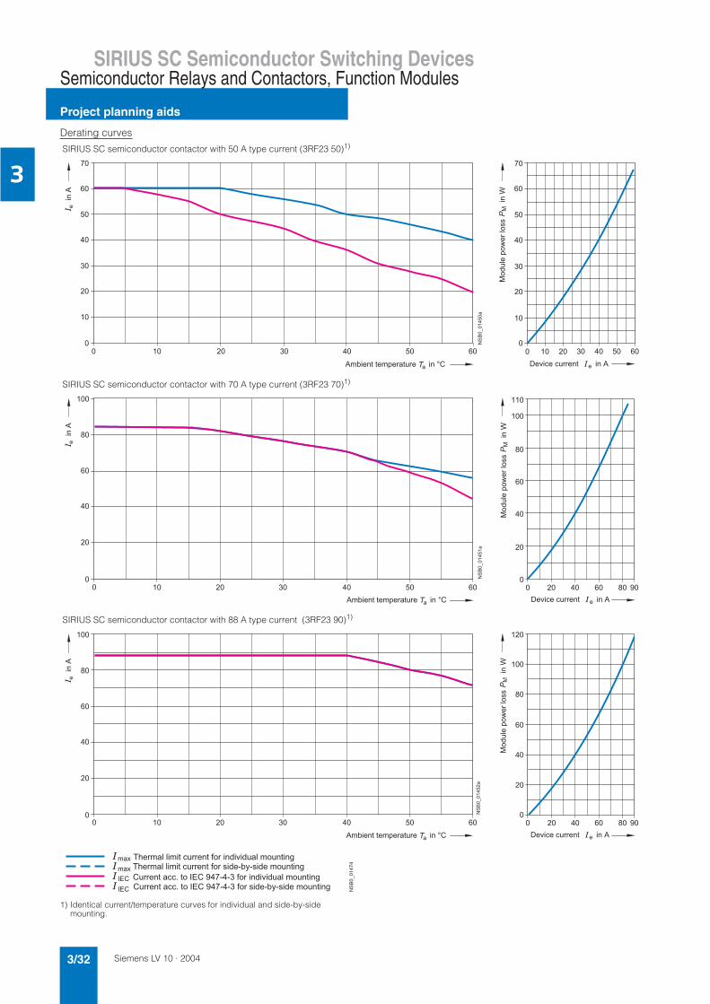
Siemens LV 10 · 20043/32
SIRIUS SC Semiconductor Switching Devices
Project planning aids
Semiconductor Relays and Contactors, Function Modules
3
Derating curves
1) Identical current/temperature curves for individual and side-by-side mounting.
SIRIUS SC semiconductor contactor with 50 A type current (3RF23 50)1)
SIRIUS SC semiconductor contactor with 70 A type current (3RF23 70)1)
SIRIUS SC semiconductor contactor with 88 A type current (3RF23 90)1)
%
%
!
"!
##$
&
!
"!
##$
&
!
"!
##$
* + % % , # $ $ % # -
* + % % , # ' $ . / . ' $ # -
" 0 # 1 2 " ) ( . . , # $ $ % # -
" 0 # 1 2 " ) ( . . , # ' $ . / . ' $ # -
3
3
1 2 "
1 2 " (

Siemens LV 10 · 2004 3/33
SIRIUS SC Semiconductor Switching DevicesSemiconductor Relays and Contactors, Function Modules
Project planning aids
3
Dimension drawings
SIRIUS SC semiconductor relays
22.5 mm semiconductor relays
45 mm semiconductor relays
)
(
)
Screw connection Spring-loaded Ring connection3RF21 .0-1AA.. connection 3RF21 .0-2AA.. 3RF21 .0-3AA..
(
3RF20 .0-1AA.
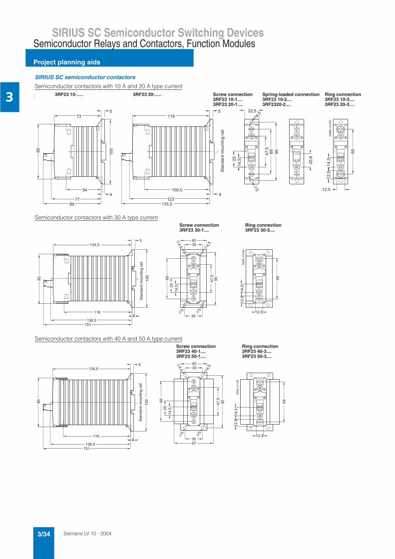
Siemens LV 10 · 20043/34
SIRIUS SC Semiconductor Switching Devices
Project planning aids
Semiconductor Relays and Contactors, Function Modules
3
SIRIUS SC semiconductor contactors
Semiconductor contactors with 10 A and 20 A type current
Semiconductor contactors with 30 A type current
Semiconductor contactors with 40 A and 50 A type current
)
(
)
)
(
)
)
(
( (
$$#-%
# $ # # # ' & + $ /
& # # - . /
# #
4 - % $
3RF23 10-..... 3RF23 20-..... Screw connection Spring-loaded connection Ring connection3RF23 10-1.... 3RF23 10-2.... 3RF23 10-3....3RF23 20-1.... 3RF2320-2.... 3RF23 20-3....
)
)
(
)
$$#-%
# $ # # # ' & + /
& # # 4 - % $
Screw connection Ring connection3RF23 30-1.... 3RF23 30-3....
(
)
)
(
)
)
# $ # # # ' & + $ / '
& # # 4 - % $
$$#-%
Screw connection Ring connection3RF23 40-1.... 3RF23 40-3....3RF23 50-1.... 3RF23 50-3....

Siemens LV 10 · 2004 3/35
SIRIUS SC Semiconductor Switching DevicesSemiconductor Relays and Contactors, Function Modules
Project planning aids
3
Semiconductor contactors with 70 A type current
Semiconductor contactors with 88 A type current
8
100
141
122,5145
157,5
123135
80 47,5
69
2514
,5
14,5
12,5
4,5
69
12,5
NS
B0_
0144
1
Screw connection Ring connection3RF23 70-1.... 3RF23 70-3....
(
(
)
)
Screw connection Ring connection3RF23 90-1.... 3RF23 90-3....

Siemens LV 10 · 20043/36
SIRIUS SC Semiconductor Switching Devices
Project planning aids
Semiconductor Relays and Contactors, Function Modules
3
Function modules for SIRIUS SC semiconductor switching devices
Converters Basic load monitoring3RF29 00-0EA18 3RF29 00-0FA08
Extended load monitoring Power controllers3RF29 .0-0GA.. 3RF29 .0-0HA..
Accessories for SIRIUS SC semiconductor switching devices
Terminal cover for SIRIUS semiconductor switching devices3RF29 00-3PA88
22,583
,521,5
3825,5
NS
B0_
0143
4 12,5
19,5
22,5
101,
5
21,5
38,5 28,5
25,5
NS
B0_
0143
5
4044
29,5
NS
B0_
0144
3
38 31,5
45
111,
5
29,5
4044
38 31,5
111,
5
45
NS
B0_
0144
4
27,5
36,5
37,5
29
22,5
12
NS
B0_
0147
2

Siemens LV 10 · 2004 3/37
SIRIUS SC Semiconductor Switching DevicesSemiconductor Relays and Contactors, Function Modules
Project planning aids
3
Circuit diagrams
SIRIUS SC semiconductor relays SIRIUS SC semiconductor contactors
DC version AC version DC version AC version
Function modules for SIRIUS SC semiconductor switching devices
Converters Basic load monitoring Extended load monitoring Power controllers
1) Internal connection.
2) Straight-through transformer.
SIRIUS SC semiconductor relays
Typical circuit diagram
)"
*
"
"
)!
"
"
)
*
"
"
)'
"
"
))
*
"
*
+
)
"+
*
"
+
),
*
"
"
&
+
"+
-./01
)2
*
"
&
*
"
&
+
"+
"
&&'("!
',
"
"
&

Siemens LV 10 · 20043/38
SIRIUS SC Semiconductor Switching Devices
Project planning aids
Semiconductor Relays and Contactors, Function Modules
3
1) Internal connection.
2) Straight-through transformer.
3) PE/ground connection for semiconductor contactors according to installa-tion regulations.
4) Connection of contact L/N to N conductor or a second phase according to the rated operational voltage of the function module.
5) In order to observe the limit values of the conducted interference voltage for generalized phase control, a choke rated at at least 200 µH must be included in the load circuit.
Function modules for SIRIUS SC semiconductor switching devices
Converters Typical circuit diagram Basic load monitoring Typical circuit diagram
Extended load monitoring Typical circuit diagram Power controllers Typical circuit diagram
"
)
'2-
"
&
+
3
*
3
*
*
&&'(&"!
*:;<
*=;<&"
" 34
*4*
"3
56
.7$
*" 3
3 *
*
"3+
"
!+
"+
&&'("!
)8
" ! ' )
&
"
)
* *=
*:
9
56
.7$
*
3 *
*
"+
"
!+
"+
!&&'("!&
"
)8
+ + + + + +
"
&
+ + + + + +
9
4
4" 3
)
*
*
*
>*=
*:
-./01
&
!":
!"=
+
*;
%
!=
! :
;:
,=
*: *=
!
!=
!->
.
)>
*
*
>
>
7
/
*=
)
*:
*
;;)6;,
%,
<
<
*
*
>
&
:

Siemens LV 10 · 2004 3/39
SIRIUS/SIKOSTART Soft Starters
General data
3
Overview
These properties apply to all soft starters:• Soft starting and smooth ramp-down1)
• Stepless starting• Reduction of current peaks• Avoidance of mains voltage fluctuations
• Reduced load on the power supply network• Reduction of the mechanical load in the operating mechanism• Considerable space savings and reduced wiring compared
with conventional starters• Maintenance-free switching• Very easy handling
Function is available- Function not available
1) Smooth ramp-down not available for 3RW31.
For more information on the Internet go towww.siemens.de/sanftstarter
3RW30 03 SIRIUS 3RW30/31 SIKOSTART 3RW34 SIKOSTART 3RW22
Rated current at 40 °C A 3 6 ... 100 57 ... 1720 7 ... 1200
Rated operating voltage V 200 ... 400 200 ... 575 200 ... 600 200 ... 1000
Motor rating at 400 V• Inline circuit kW 0.1 ... 1.1 1.1 ... 55 30 ... 630 3 ... 710• Inside-delta circuit kW - - 45 ... 1000 -
Temperature range °C -25 ... +60 -25 ... +60 0 ... +60 0 ... +55
Starting voltage % 40 ... 100 40 ... 100 30 ... 80 20 ... 100
Starting and ramp-down time s 0.1 ... 20 0.1 ... 20 0.5 ... 60 0.3 ... 180 (0 ... 1000 with COM-SIKOSTART)
Number of parameter sets 1 1(2 with 3RW31)
1 13 (with COM-SIKOSTART)
Power semiconductors: thyristors
in 2 phases in 2 phases in 3 phases in 3 phases
Degree of protection IP20 IP20 IP00 IP20/IP00 from 100 A
Built-in bypass contacts - - -
Optional inside-delta circuit - - -
Current limiting - - -
Voltage limiting - - -
Pump running down - - -
Energy saving - - -
DC braking - - -
Breakaway pulse - - -
Electronic overload protection - - -
Communication - with AS-Interface module - PC interface, combinable with SIMOCODE-DP
Calibration software - - - (COM -SIKOSTART)
UL – CSA () up to 230 V () up to 70 A
CE marking
Approved for potentiallyexplosive atmospheres
- -
Soft starting under heavystarting conditions
- -
Configuring support Win-SIKOSTART, electronic selection slide
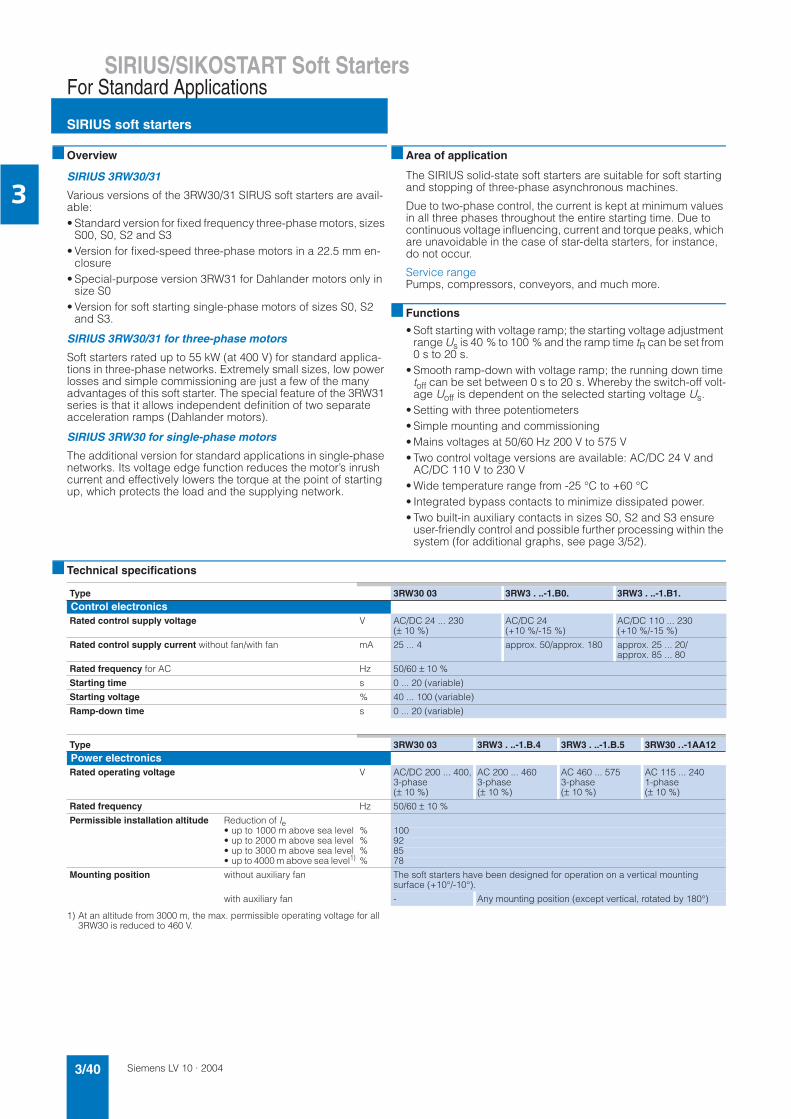
Siemens LV 10 · 20043/40
SIRIUS/SIKOSTART Soft Starters
SIRIUS soft starters
For Standard Applications
3
Overview
SIRIUS 3RW30/31
Various versions of the 3RW30/31 SIRUS soft starters are avail-able:• Standard version for fixed frequency three-phase motors, sizes
S00, S0, S2 and S3• Version for fixed-speed three-phase motors in a 22.5 mm en-
closure• Special-purpose version 3RW31 for Dahlander motors only in
size S0• Version for soft starting single-phase motors of sizes S0, S2
and S3.
SIRIUS 3RW30/31 for three-phase motors
Soft starters rated up to 55 kW (at 400 V) for standard applica-tions in three-phase networks. Extremely small sizes, low power losses and simple commissioning are just a few of the many advantages of this soft starter. The special feature of the 3RW31 series is that it allows independent definition of two separate acceleration ramps (Dahlander motors).
SIRIUS 3RW30 for single-phase motors
The additional version for standard applications in single-phase networks. Its voltage edge function reduces the motor’s inrush current and effectively lowers the torque at the point of starting up, which protects the load and the supplying network.
Area of application
The SIRIUS solid-state soft starters are suitable for soft starting and stopping of three-phase asynchronous machines.
Due to two-phase control, the current is kept at minimum values in all three phases throughout the entire starting time. Due to continuous voltage influencing, current and torque peaks, which are unavoidable in the case of star-delta starters, for instance, do not occur.
Service rangePumps, compressors, conveyors, and much more.
Functions
• Soft starting with voltage ramp; the starting voltage adjustment range Us is 40 % to 100 % and the ramp time tR can be set from 0 s to 20 s.
• Smooth ramp-down with voltage ramp; the running down time toff can be set between 0 s to 20 s. Whereby the switch-off volt-age Uoff is dependent on the selected starting voltage Us.
• Setting with three potentiometers• Simple mounting and commissioning• Mains voltages at 50/60 Hz 200 V to 575 V• Two control voltage versions are available: AC/DC 24 V and
AC/DC 110 V to 230 V• Wide temperature range from -25 °C to +60 °C• Integrated bypass contacts to minimize dissipated power.• Two built-in auxiliary contacts in sizes S0, S2 and S3 ensure
user-friendly control and possible further processing within the system (for additional graphs, see page 3/52).
Technical specifications
1) At an altitude from 3000 m, the max. permissible operating voltage for all 3RW30 is reduced to 460 V.
Type 3RW30 03 3RW3 . ..-1.B0. 3RW3 . ..-1.B1.Control electronicsRated control supply voltage V AC/DC 24 ... 230
(± 10 %)AC/DC 24(+10 %/-15 %)
AC/DC 110 ... 230 (+10 %/-15 %)
Rated control supply current without fan/with fan mA 25 ... 4 approx. 50/approx. 180 approx. 25 ... 20/ approx. 85 ... 80
Rated frequency for AC Hz 50/60 ± 10 %
Starting time s 0 ... 20 (variable)
Starting voltage % 40 ... 100 (variable)
Ramp-down time s 0 ... 20 (variable)
Type 3RW30 03 3RW3 . ..-1.B.4 3RW3 . ..-1.B.5 3RW30 ..-1AA12Power electronicsRated operating voltage V AC/DC 200 ... 400,
3-phase(± 10 %)
AC 200 ... 460 3-phase(± 10 %)
AC 460 ... 575 3-phase(± 10 %)
AC 115 ... 240 1-phase(± 10 %)
Rated frequency Hz 50/60 ± 10 %
Permissible installation altitude Reduction of Ie• up to 1000 m above sea level % 100• up to 2000 m above sea level % 92• up to 3000 m above sea level % 85• up to 4000 m above sea level1) % 78
Mounting position without auxiliary fan The soft starters have been designed for operation on a vertical mountingsurface (+10°/-10°).
with auxiliary fan - Any mounting position (except vertical, rotated by 180°)

Siemens LV 10 · 2004 3/41
SIRIUS/SIKOSTART Soft StartersFor Standard Applications
SIRIUS soft starters
3
1) The rated motor current (specified on the motor's name plate) should at least amount to the specified percentage of the SIRIUS soft starter's rated operational current Ie.
Type 3RW30 03 3RW30 1. 3RW30 2. 3RW30 3. 3RW30 4.
Size S00 S0 S2 S3
Continuous operation (% of Ie) % 100
Minimum load1) (% of Ie); at 40 °C % 9 4
Permissible ambient temperature Operation °C -25 ... +60 (derating from 40 °C, see load rating)Storage °C -25 ... +80
Switching capacity of the auxiliary contacts
230 V/AC-15 A No auxiliary contacts available 3 3 3230 V/DC-13 A 0.1 0.1 0.124 V/DC-13 A 1 1 1
Type 3RW30 03 3RW30 14 3RW30 16 3RW3. 24 3RW3. 25 3RW3. 26
Load rating
Rated operating current Ie• Acc. to IEC
for individual mountingat 40/50/60 °C, AC-53b A - 6/5/4 9/8/7 12.5/11/9 16/14/12 25/21/18
• Acc. to UL/CSA for individual mounting
at 40/50/60 °C, AC-53b A - 4.8/4.8/4 7.8/7.8/7 11/11/9 17.5/14/12 25/21/18
• Acc. to IEC/UL/CSA for individual mounting
at 40/50/60 °C, AC-53a A 3/2.6/2.2 -
• acc. to IEC/UL/CSA for side-by-side mounting
at 40/50/60 °C, AC-53a A 2.6/2.2/1.8 -
Power loss
at continuous rated operating current (40 °C) approx. W 6.5 5 7 7 9 13at utilization of max. operating frequency (40 °C) approx. W 3 5 6 7 8 9
Permissible starts per hour without using a fan
for intermittent duty S4, Tu = 40 °C, individual mounting vertical 1/h 1500 60 40 30 12ON-period = 30 % % Ie/s - 250/2 300/2ON-period = 70 % % Ie/s 300/0.2 -
Permissible starts per hour when using a fan
for intermittent duty S4, Tu = 40 °C, individual mounting, ON-period = 30 %
1/h Fans cannot be fitted 54 21
Pause intervals after continuous duty
with Ie before a new start s 0 200
Degree of protection acc. to IEC 60529 IP20 (IP00 terminal enclosure)
Maximum conductor length between soft starter and motor m 1001)
Conductor cross-sections
Screw-type terminals Main conductors
(1 or 2 conductor connections)for standard screw driversize 2 and Pozidriv 2
• Solid mm² 1 x (0.5 ... 4);2 x (0.5 ... 2.5)
2 x (0.5 ... 1.5);2 x (0.75 ... 2.5)
2 x (1 ... 2.5); 2 x (2.5 ... 6)
• Finely strandedwith end sleeve
mm² 1 x (0.5 ... 2.5);2 x (0.5 ... 1.5)
2 x (0.5 ... 2.5) 2 x (1 ... 2.5); 2 x (2.5 ... 6)
• Stranded mm² - - -• AWG conductors,
solid or stranded AWG 2 x (20 ... 14) 2 x (18 ... 14) 2 x (14 ... 10)• Terminal screws M3, PZ2 M4, PZ2
- Tightening torque Nm 0.8 ... 1.2 2 ... 2.2lb.in 7.1 ... 8.9 7 ... 10.3 18 ... 22
Auxiliary conductors
• Solid mm² 1 x (0.5 ... 4); 2 x (0.5 ... 2.5)
2 x (0.5 ... 1.5); 2 x (0.75 ... 2.5) to IEC 60947; max. 2 x (0.75 ... 4)
• Finely strandedwith end sleeve
mm² 1 x (0.5 ... 2.5); 2 x (0.5 ... 1.5)
2 x (0.5 ... 1.5); 2 x (0.75 ... 2.5)
• AWG conductors,solid or stranded AWG 2 x (20 ... 14) 2 x (18 ... 14)
• Terminal screws M3, PZ2- Tightening torque Nm 0.8 ... 1.2 0.8 ... 1
lb.in 7 ... 8.9 7.1 ... 8.9
Spring-loaded terminals Main and auxiliaryconductors
• Solid mm² 2 x (0.25 ... 1.5) -• Finely stranded
with end sleevemm² 2 x (0.25 ... 1) -
• AWG conductors,solid or stranded AWG 2 x (24 ... 16) -
1) If this value is exceeded, problems with line capacities may arise, whichcan result in false firing.

Siemens LV 10 · 20043/42
SIRIUS/SIKOSTART Soft Starters
SIRIUS soft starters
For Standard Applications
3
1) IP20 only with installed box terminal ('as-delivered'). Without box terminal IP00.
2) If this value is exceeded, problems with line capacities may arise, which can result in false firing.
Type 3RW30 34 3RW30 35 3RW30 36 3RW30 44 3RW30 45 3RW30 46Power electronicsLoad rating
Rated operating current Ie• Acc. to IEC
for individual mountingat 40/50/60 °C, AC-53b A 32/27/23 38/32/27 45/38/32 63/54/46 75/64/54 100/85/72
• Acc. to UL/CSAfor individual mounting
at 40/50/60 °C, AC-53b A 27/27/23 34/32/27 42/38/32 62/54/46 68/64/54 99/85/72
Power loss
at continuous rated operating current (40 °C) approx. W 10 13 17 13 16 26at utilization of max. operating frequency (40 °C) approx. W 11 11 10 18 29 26
Permissible starts per hour when not using a fan
for intermittent duty S4, Tu = 40 °C, individual mounting vertical 1/h 20 15 5 20 30 15ON-period = 30 % % Ie/s 300/3 300/4
Permissible starts per hour when using a fan
for intermittent duty S4, Tu = 40 °C, individual mounting, ON-period = 30 %
1/h 44 27 9 32 48 24
Pause intervals after continuous dutywith Ie before a new start s 0 400 0
Protection acc. to IEC 60529 IP20 (IP00 terminal enclosure) IP201)
Maximum conductor length between soft starter and motor m 1002)
Conductor cross-sections
Screw-type terminals Main conductors
(1 or 2 conductor connections)for standard screw driversize 2 and Pozidriv 2
• Solid mm² 2 x (0.75 ... 16)• Finely stranded
with end sleevemm² 2 x (0.75 ... 16)
1 x (0.75 ... 25)• Stranded mm² 2 x (0.75 ... 25)
1 x (0.75 ... 35)2 x (10 ... 50)1 x (10 ... 70)
• AWG conductors,solid or stranded AWG 2 x (18 ... 3); 1 x (18 ... 2) 2 x (10 ...1/0) 1 x (10 ... 2/0)
• Terminal screws M6, box terminal, PZ2 M6 (Inbus)- Tightening torque Nm 3 ... 4.5 4 ... 6
lb.in 27 ... 40 35 ... 53
Auxiliary conductors
• Solid mm² 2 x (0.5 ... 1.5); 2 x (0.75 ... 2.5) accord. to IEC 60947; max. 2 x (0.75 ... 4)• Finely stranded
with end sleevemm² 2 x (0.5 ... 1.5); 2 x (0.75 ... 2.5)
• AWG conductors,solid or stranded
AWG 2 x (18 ... 14)
• Terminal screws M3- Tightening torque Nm 0.8 ... 1
lb.in 7.1 ... 8.9
Standard ParametersElectromagnetic compatibility acc. to EN 60947-4-2EMC interference immunity Electrostatic discharge (ESD) IEC 61000-4-2 Degree of severity 3: 6/8 kV
Electromagnetic RF fields IEC 60947-4-2 Frequency range: 80 ... 1000 MHz with 80 % at 1 kHzDegree of severity 3, 10 V/m
Conducted RF interference IEC 61000-4-6 Frequency range: 80 ... 1000 MHz with 80 % at 1 kHz IEC 60947-4-2 10 V at 0.15 ... 80 MHzSN-IACS 3 V at 10 kHz ... 80 MHz
Burst IEC 61000-4-4 Degree of severity 3: 1/2 kV
Surge IEC 61000-4-5 Degree of severity 3: 1/2 kV
EMC emitted interference EMC interference field strength CISPR 11/09. 1990 Class B limit at 30 ... 1000 MHz
Radio interference voltage CISPR 11/09. 1990 (0.15 ... 30 MHz): Device Class A (industrial)IEC 60 947-4-2
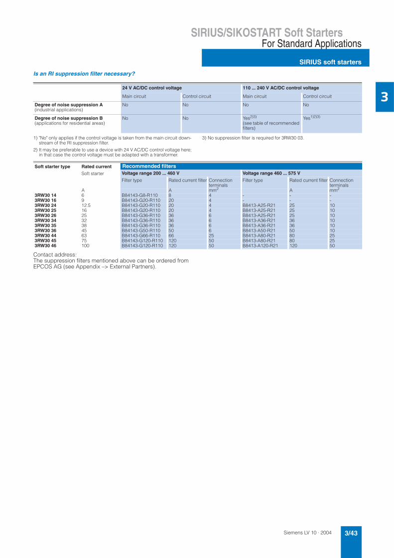
Siemens LV 10 · 2004 3/43
SIRIUS/SIKOSTART Soft StartersFor Standard Applications
SIRIUS soft starters
3
Is an RI suppression filter necessary?
1) "No" only applies if the control voltage is taken from the main circuit down-stream of the RI suppression filter.
2) It may be preferable to use a device with 24 V AC/DC control voltage here; in that case the control voltage must be adapted with a transformer.
3) No suppression filter is required for 3RW30 03.
Contact address:The suppression filters mentioned above can be ordered fromEPCOS AG (see Appendix –> External Partners).
24 V AC/DC control voltage 110 ... 240 V AC/DC control voltage
Main circuit Control circuit Main circuit Control circuit
Degree of noise suppression A (industrial applications)
No No No No
Degree of noise suppression B(applications for residential areas)
No No Yes2)3)
(see table of recommended filters)
Yes1)2)3)
Soft starter type Rated current
Soft starter
Recommended filters Voltage range 200 ... 460 V Voltage range 460 ... 575 V
Filter type Rated current filter Connectionterminals
Filter type Rated current filter Connectionterminals
A A mm2 A mm2
3RW30 14 6 B84143-G8-R110 8 4 - - -3RW30 16 9 B84143-G20-R110 20 4 - - -3RW30 24 12.5 B84143-G20-R110 20 4 B8413-A25-R21 25 103RW30 25 16 B84143-G20-R110 20 4 B8413-A25-R21 25 103RW30 26 25 B84143-G36-R110 36 6 B8413-A25-R21 25 103RW30 34 32 B84143-G36-R110 36 6 B8413-A36-R21 36 103RW30 35 38 B84143-G36-R110 36 6 B8413-A36-R21 36 103RW30 36 45 B84143-G50-R110 50 6 B8413-A50-R21 50 103RW30 44 63 B84143-G66-R110 66 25 B8413-A80-R21 80 253RW30 45 75 B84143-G120-R110 120 50 B8413-A80-R21 80 253RW30 46 100 B84143-G120-R110 120 50 B8413-A120-R21 120 50

Siemens LV 10 · 20043/44
SIRIUS/SIKOSTART Soft Starters
SIRIUS soft starters
For Standard Applications
3
Fuse assignment
The coordination type to which the motor feeder with soft starter is mounted depends on the application-specific requirements. Normally, fuseless mounting (combination of circuit-breaker and
soft starter) is sufficient. If type 2 coordination is to be fulfilled, semiconductor fuses must be fitted in the motor feeder.
1) The rated motor current defines the selection of units.
2) Pay attention to quantity units.
3) The types of coordination are explained in more detail under Load Feeders -> Fuseless Load Feeders.
1) The types of coordination are explained in more detail under Load Feeders -> Fuseless Load Feeders.
2) 3NA38 05-1 (NH00), 5SB26 1 (DIAZED), 5SE22 01-06 (NEOZED).
3) Iq = 50 kA up to max. of 400 V.
4) Iq = 50 kA up to max. of 500 V.
Fuseless version
Soft starter Circuit-breaker 1) Link module 2)
Type Type Type
G1 Q1
Type of coordination 13): Iq = 50 kA at 400 V
3RW30 03 3RV10 11 -3RW30 14 3RV10 11 3RA19 11-1A3RW30 16 3RV10 11 3RA19 11-1A3RW30 24/3RW31 24 3RV10 21 3RA19 21-1A3RW30 25/3RW31 25 3RV10 21 3RA19 21-1A3RW30 26/3RW31 26 3RV10 21 3RA19 21-1A3RW30 34 3RV10 31 3RA19 31-1A3RW30 35 3RV10 31 3RA19 31-1A3RW30 36 3RV10 31 3RA19 31-1A3RW30 44 3RV10 41 3RA19 41-1A3RW30 45 3RV10 41 3RA19 41-1A3RW30 46 3RV10 41 3RA19 41-1A
5
6
Fused version (line protection only)
Soft starter Line protection Overload relay Contactor
Thermaltype
Solid-statetype Type Type Rated current Size Type
G1 F1 F2 K1A
Type of coordination 11): Iq = 50 kA at 400 V
3RW30 03 3NA3 8052) 20 000 3RU11 16 3RB10 16 3RT10 153RW30 14 3NA3 807 20 000 3RU11 163) 3RB10 163) 3RT10 153RW30 16 3NA3 807 20 000 3RU11 163) 3RB10 163) 3RT10 163RW30 24/3RW31 24 3NA3 807 20 000 3RU11 264) 3RB10 264) 3RT10 243RW30 25/3RW31 25 3NA3 810 25 000 3RU11 264) 3RB10 264) 3RT10 253RW30 26/3RW31 26 3NA3 814 35 000 3RU11 264) 3RB10 264) 3RT10 263RW30 34 3NA3 822 63 000 3RU11 364) 3RB10 36 3RT10 343RW30 35 3NA3 822 63 000 3RU11 364) 3RB10 36 3RT10 353RW30 36 3NA3 824 80 000 3RU11 364) 3RB10 36 3RT10 363RW30 44 3NA3 830 100 000 3RU11 464) 3RB10 46 3RT10 443RW30 45 3NA3 132 125 1 3RU11 464) 3RB10 46 3RT10 453RW30 46 3NA3 140 200 1 3RU11 464) 3RB10 46 3RT10 46
7
(
7
5

Siemens LV 10 · 2004 3/45
SIRIUS/SIKOSTART Soft StartersFor Standard Applications
SIRIUS soft starters
3
1) Contactor and overload relay as in "Fused version (line protection only)" table.
2) The types of coordination are explained in more detail under Load Feeders -> Fuseless Load Feeders.
3) No SITOR fuse required!Alternatively: 3NA38 03 (NH00), 5SB22 1 (DIAZED), 5SE22 06 (NEOZED).
4) Fuse coordination for up to 400 V.
5) Fuse coordination for up to 500 V.
6) Fuse coordination with all-range fuses not possible; it may be necessary to use a pure semiconductor protection fuse plus a circuit-breaker.
1) Contactor and overload relay as above.
2) The rated motor current defines the selection of units.
3) Pay attention to quantity units.
4) The types of coordination are explained in more detail under Load Feeders -> Fuseless Load Feeders.
5) No SITOR fuse required!Alternatively: 3NA38 03 (NH00), 5SB22 1 (DIAZED), 5SE22 06 (NEOZED).
6) Fuse coordination with semiconductor protection fuses not possible; it may be necessary to use pure 3NE1..-0 all-range fuses or the next highest soft starter.
Fused version with 3NE1 SITOR fuses (semiconductor and line protection1)
Soft starter All-range fuse
Type Rated current SizeType
G1 F'1A
Type of coordination 22): Iq = 50 kA at 400 V/500 V
3RW30 03 3NE1 813-03) 16 0003RW30 14 3NE1 814-04) 20 0003RW30 16 3NE1 815-05) 25 0003RW30 24/3RW31 24 3NE1 815-05) 25 0003RW30 25/3RW31 25 3NE1 815-05) 25 0003RW30 26/3RW31 26 3NE1 802-05) 40 0003RW30 34 3NE1 818-05) 63 0003RW30 35 3NE1 820-05) 80 0003RW30 36 3NE1 820-05) 80 0003RW30 44 3NE1 820-05) 80 0003RW30 45 3NE1 821-05) 100 003RW30 46 -6) - -
Fused version with 3NE8 SITOR fuses1) (semiconductor protection by fuse, lead and overload protection by circuit-breaker; alternatively, installation with contactor and overload relay possible)
Soft starter Semiconductor protection fuse Circuit-breaker 2) Link module3)
Type Rated current Size Type TypeType
G1 F3 Q1A
Type of coordination 24): Iq = 50 kA at 400 V
3RW30 03 3NE8 015-1 25 00 3RV10 115) 3RA19 11-1A3RW30 14 3NE8 003-1 35 00 3RV10 11 3RA19 11-1A3RW30 16 3NE8 003-1 35 00 3RV10 11 3RA19 11-1A3RW30 24/3RW31 24 3NE8 003-1 35 00 3RV10 21 3RA19 21-1A3RW30 25/3RW31 25 3NE8 003-1 35 00 3RV10 21 3RA19 21-1A3RW30 26/3RW31 26 -6) - - - -3RW30 34 3NE8 022-1 125 00 3RV10 31 3RA19 31-1A3RW30 35 3NE8 024-1 160 00 3RV10 31 3RA19 31-1A3RW30 36 3NE8 024-1 160 00 3RV10 31 3RA19 31-1A3RW30 44 3NE8 024-1 160 00 3RV10 41 3RA19 41-1A3RW30 45 3NE8 024-1 160 00 3RV10 41 3RA19 41-1A3RW30 46 3NE8 024-1 160 00 3RV10 41 3RA19 41-1A
7
)
5
6
7
7
5
7
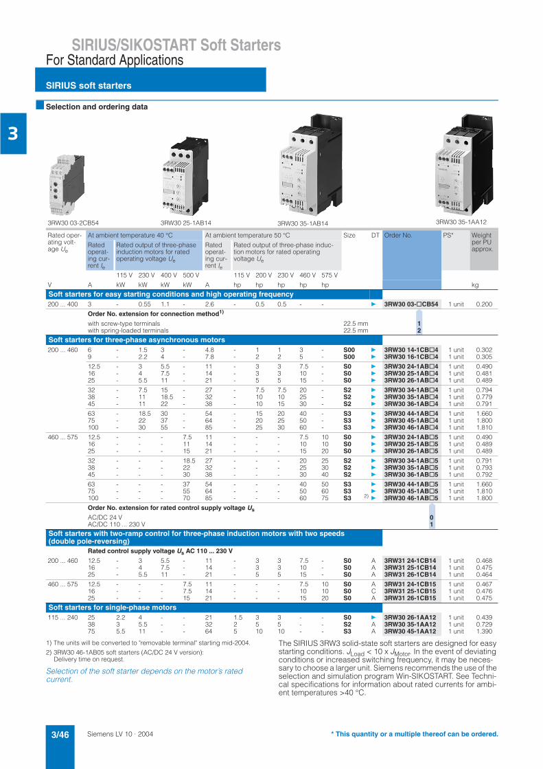
Siemens LV 10 · 20043/46
SIRIUS/SIKOSTART Soft Starters
SIRIUS soft starters
For Standard Applications
3
Selection and ordering data
1) The units will be converted to "removable terminal" starting mid-2004.
2) 3RW30 46-1AB05 soft starters (AC/DC 24 V version):Delivery time on request.
Selection of the soft starter depends on the motor’s ratedcurrent.
The SIRIUS 3RW3 solid-state soft starters are designed for easy starting conditions. JLoad < 10 x JMotor. In the event of deviating conditions or increased switching frequency, it may be neces-sary to choose a larger unit. Siemens recommends the use of the selection and simulation program Win-SIKOSTART. See Techni-cal specifications for information about rated currents for ambi-ent temperatures >40 °C.
3RW30 03-2CB54 3RW30 25-1AB14 3RW30 35-1AB14 3RW30 35-1AA12
Rated oper-ating volt-age Ue
At ambient temperature 40 °C At ambient temperature 50 °C Size DT Order No. PS* Weight per PU approx.
Ratedoperat-ing cur-rent Ie
Rated output of three-phase induction motors for rated operating voltage Ue
Ratedoperat-ing cur-rent Ie
Rated output of three-phase induc-tion motors for rated operating voltage Ue
115 V 230 V 400 V 500 V 115 V 200 V 230 V 460 V 575 V
V A kW kW kW kW A hp hp hp hp hp kg
Soft starters for easy starting conditions and high operating frequency200 ... 400 3 - 0.55 1.1 - 2.6 - 0.5 0.5 - - 3RW30 03-@CB54 1 unit 0.200
Order No. extension for connection method1)
with screw-type terminals 22.5 mm 1with spring-loaded terminals 22.5 mm 2
Soft starters for three-phase asynchronous motors200 ... 460 6 - 1.5 3 - 4.8 - 1 1 3 - S00 3RW30 14-1CB@4 1 unit 0.302
9 - 2.2 4 - 7.8 - 2 2 5 - S00 3RW30 16-1CB@4 1 unit 0.305
12.5 - 3 5.5 - 11 - 3 3 7.5 - S0 3RW30 24-1AB@4 1 unit 0.49016 - 4 7.5 - 14 - 3 3 10 - S0 3RW30 25-1AB@4 1 unit 0.48125 - 5.5 11 - 21 - 5 5 15 - S0 3RW30 26-1AB@4 1 unit 0.489
32 - 7.5 15 - 27 - 7.5 7.5 20 - S2 3RW30 34-1AB@4 1 unit 0.79438 - 11 18.5 - 32 - 10 10 25 - S2 3RW30 35-1AB@4 1 unit 0.77945 - 11 22 - 38 - 10 15 30 - S2 3RW30 36-1AB@4 1 unit 0.791
63 - 18.5 30 - 54 - 15 20 40 - S3 3RW30 44-1AB@4 1 unit 1.66075 - 22 37 - 64 - 20 25 50 - S3 3RW30 45-1AB@4 1 unit 1.800100 - 30 55 - 85 - 25 30 60 - S3 3RW30 46-1AB@4 1 unit 1.810
460 ... 575 12.5 - - - 7.5 11 - - - 7.5 10 S0 3RW30 24-1AB@5 1 unit 0.49016 - - - 11 14 - - - 10 10 S0 3RW30 25-1AB@5 1 unit 0.48925 - - - 15 21 - - - 15 20 S0 3RW30 26-1AB@5 1 unit 0.489
32 - - - 18.5 27 - - - 20 25 S2 3RW30 34-1AB@5 1 unit 0.79138 - - - 22 32 - - - 25 30 S2 3RW30 35-1AB@5 1 unit 0.79345 - - - 30 38 - - - 30 40 S2 3RW30 36-1AB@5 1 unit 0.792
63 - - - 37 54 - - - 40 50 S3 3RW30 44-1AB@5 1 unit 1.66075 - - - 55 64 - - - 50 60 S3 3RW30 45-1AB@5 1 unit 1.810100 - - - 70 85 - - - 60 75 S3 2)
3RW30 46-1AB@5 1 unit 1.800
Order No. extension for rated control supply voltage Us
AC/DC 24 V 0AC/DC 110 ... 230 V 1
Soft starters with two-ramp control for three-phase induction motors with two speeds(double pole-reversing)
Rated control supply voltage Us AC 110 ... 230 V
200 ... 460 12.5 - 3 5.5 - 11 - 3 3 7.5 - S0 A 3RW31 24-1CB14 1 unit 0.46816 - 4 7.5 - 14 - 3 3 10 - S0 A 3RW31 25-1CB14 1 unit 0.47525 - 5.5 11 - 21 - 5 5 15 - S0 A 3RW31 26-1CB14 1 unit 0.464
460 ... 575 12.5 - - - 7.5 11 - - - 7.5 10 S0 A 3RW31 24-1CB15 1 unit 0.46716 - - - 7.5 14 - - - 10 10 S0 C 3RW31 25-1CB15 1 unit 0.47625 - - - 15 21 - - - 15 20 S0 A 3RW31 26-1CB15 1 unit 0.475
Soft starters for single-phase motors115 ... 240 25 2.2 4 - - 21 1.5 3 3 - - S0 3RW30 26-1AA12 1 unit 0.439
38 3 5.5 - - 32 2 5 5 - - S2 A 3RW30 35-1AA12 1 unit 0.72975 5.5 11 - - 64 5 10 10 - - S3 A 3RW30 45-1AA12 1 unit 1.390
* This quantity or a multiple thereof can be ordered.

Siemens LV 10 · 2004 3/47
SIRIUS/SIKOSTART Soft StartersFor Standard Applications
SIRIUS soft starters
3
Accessories
1) With internal soft starter power supply.
Forsoft starters
Size Version DT Order No. PS* Weight per PU approx.
Type kg
Fans1)
3RW39 26-8A
3RW39 36-8A
3RW3. 2. S0 To increase switching frequency and for unit mounting in positions different from the nor-mal position. The fan is snapped into the enclosure from below. During operation, (control signal input “IN” at potential A1), the fan is running. After a stop, the fan continues to run for about another 60 minutes.
3RW39 26-8A 1 unit 0.0083RW30 3. and 3RW30 4.
S2S3
3RW39 36-8A 1 unit 0.030
CoversTerminal cover for box terminals
3RT19 36-4EA2
3RW30 3. S2 Additional shock-hazard protection for fitting to box terminals (2 units required per contactor)
3RT19 36-4EA2 1 unit 0.0203RW30 4. S3 3RT19 46-4EA2 1 unit 0.017
Terminal cover for cable lug and busbar connection
3RT19 46-4EA1
3RW30 4. S3 For complying with the phase clearances and as shock-hazard protection in the case of a distant box terminal (2 units required per con-tactor)
3RT19 46-4EA1 1 unit 0.037
Version FunctionalityFunctions
Application DT Order No. PS* Weight per PU approx.
kgCovering cap and plug-in lug (only for 3RW30 03)
Sealable cap
for securing against unauthorized maladjustment of setting knobs
for units with 1 or 2 changeover contacts
3RP19 02 5 units 0.019
Push-in lugfor screw fixing
for units with 1 or 2 changeover contacts
3RP19 03 10units
0.018
* This quantity or a multiple thereof can be ordered.

Siemens LV 10 · 20043/48
SIRIUS/SIKOSTART Soft Starters
SIRIUS soft starters
For Standard Applications
3
Note:The covers and connection modules listed here are also used for load feeders (3RV circuit-breaker + 3RT contactor).
For further technical specifications see Controlgear –> Contactors and contactor assemblies.For fuseless load feeders with size S00 soft starter, the link module has an integrated conductor routing.
1) Computer labeling system for individual labeling of device labeling plates available from:murrplastik Systemtechnik GmbH (see Appendix –> External Partners).
Forsoft starters
Size Version DT Order No. PS* Weight per PU approx.
Type kgLink modules
3RA19 11-1A
3RA19 21-1A
3RA19 31-1A
Electrical and mechanical link between circuit-breaker and soft starter.
Individually packaged3RW30 1.. S00 3RA19 11-1AA00 1 unit 0.0273RW30 2.. S0 3RA19 21-1AA00 1 unit 0.0373RW30 3.. S2 3RA19 31-1AA00 1 unit 0.0423RW30 4.. S3 3RA19 41-1AA00 1 unit 0.090
Multi-pack3RW30 1.. S00 3RA19 11-1A 10
units0.193
3RW30 2.. S0 3RA19 21-1A 10units
0.276
3RW30 3.. S2 3RA19 31-1A 5 units 0.1633RW30 4.. S3 3RA19 41-1A 5 units 0.366
Designation Labeling area/color DT Order No. PS* Weight per PU approx.
W x Hmm x mm kg
Blank labeling plates
Item code labels1 frame = 20 labels
Item code labels for "SIRIUS"1)
20 x 7 pastel turquoise
A 3RT19 00-1SB20 340units
0.067
"SIRIUS" labels for sticking 19 x 6 pastel turquoise
D 3RT19 00-1SB60 4700units
0.003
19 x 6 zinc yellow
C 3RT19 00-1SD60 4700units
0.003
NS
K-7
237
* This quantity or a multiple thereof can be ordered.

Siemens LV 10 · 2004 3/49
SIRIUS/SIKOSTART Soft StartersFor Standard Applications
SIRIUS soft starters
3
1) Without connectors for data and auxiliary power (yellow and black).
2) With one connector each for data and auxiliary power (yellow and red).
For busbar accessories, see Load feeders –> Busbar Adapter System.
For soft starters Version DT Order No. PS* Weight per PU approx.
Type kgAS-Interface load feeder modules
3RK14 00-1KG01-0AA1 3RK14 00-1MG01-0AA1
AS-Interface load feeder modules for mounting onto standard mounting railsSizes S00 and S0 For mounting onto 40 mm or 60 mm busbar systems and SIRIUS standard rail adapters, the matching support is required (see 3RK1 901-3GA00) The AS-Interface connectors for the data and auxiliary power cable (yellow and black) must be ordered sepa-rately (see 3RK1 901-0.A00)
2 inputs/1 output/DC 24 V1) 3RK1 400-1KG01-0AA1 1 unit 0.097
4 inputs/2 outputs/DC 24 V1) 3RK1 400-1MG01-0AA1 1 unit 0.100
2 inputs/1 relay output/AC 120/230 V2) 3RK1 402-3KG02-0AA1 1 unit 0.124
3 inputs/2 relay outputs AC 120/230 V2) 3RK1 402-3LG02-0AA1 1 unit 0.134
Manual for AS-Interface load feeder module
German, English 3RK1 701-2GB00-0AA0 1 unit 0.197Italian, French A 3RK1 701-2HB00-0AA0 1 unit 0.196
Support for AS-Interface load feeder module
for mounting onto 3RA19 22-1A SIRIUS standard mounting rail adapter
45 mm X 3RK1 901-3GA00 1 unit 0.048
Support with mounted power connector coupling
Power connector set5-pin, 2.5 mm2
(1 package = 5 connectors and 5 couplers)
A 3RK1 901-0EA00 5 units 0.111
3RK19 01-0NA00 3RK19 01-0PA00
AS-Interface connector for data and auxiliary supply cables
with overlapping terminals for 2 x (0.5 to 0.75 mm2) flexible lead
yellow 3RK1 901-0NA00 5 units 0.015
with overlapping terminals for 2 x (0.5 to 0.75 mm2) flexible lead
black 3RK1 901-0PA00 5 units 0.015
Standard mounting rail adapter
3RA19 22
3RW30 1. Standard mounting rail adapterfor mechanical mounting of circuit-breaker and contactor; can be snapped onto standard rail or for screw mounting, suitable for size S00
3RA19 22-1A 5 units 0.474
Surge suppressor - RC element for PLC control
3TX7 462-3.
RC elementFor lateral snapping onto auxiliary switch or 35 mm standard mounting rail
AC 127 V ... 240 V 3TX7 462-3T 1 unit 0.080
* This quantity or a multiple thereof can be ordered.
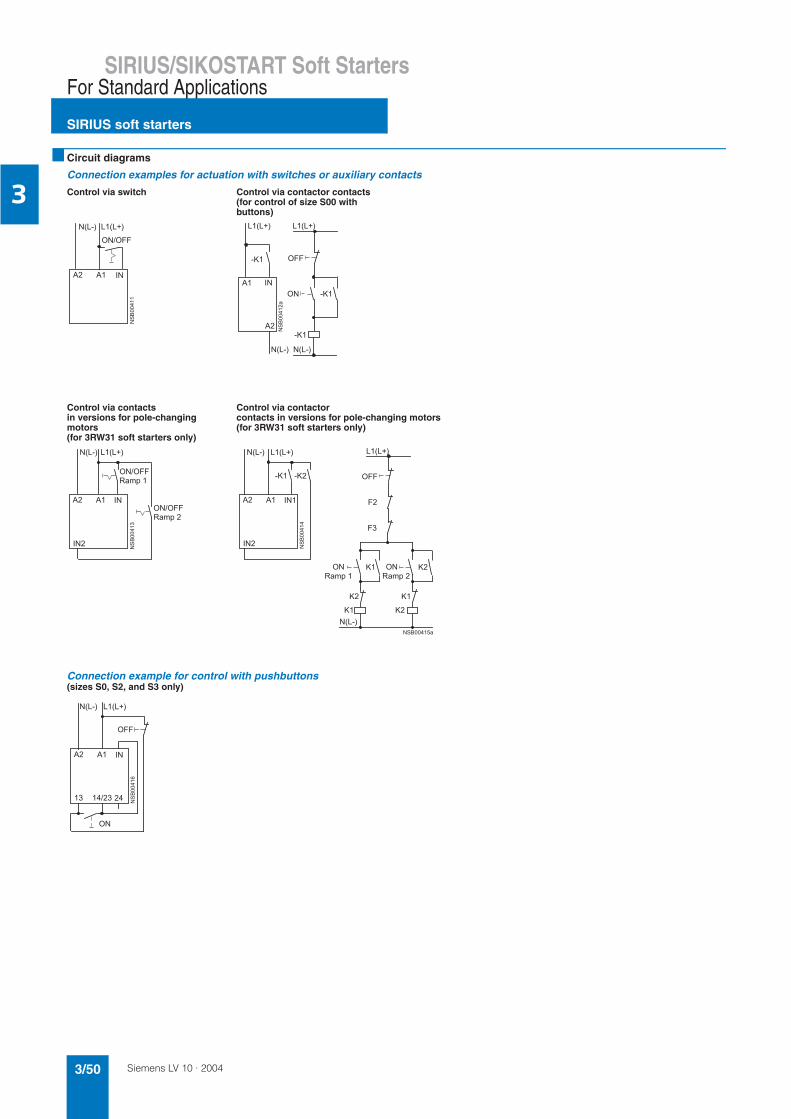
Siemens LV 10 · 20043/50
SIRIUS/SIKOSTART Soft Starters
SIRIUS soft starters
For Standard Applications
3
Circuit diagrams
Connection examples for actuation with switches or auxiliary contacts
Control via switch Control via contactor contacts (for control of size S00 with buttons)
Control via contactsin versions for pole-changing motors (for 3RW31 soft starters only)
Control via contactor contacts in versions for pole-changing motors (for 3RW31 soft starters only)
Connection example for control with pushbuttons(sizes S0, S2, and S3 only)
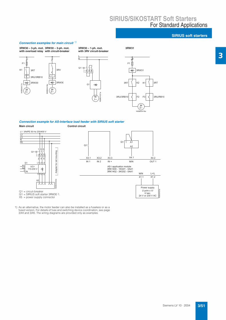
Siemens LV 10 · 2004 3/51
SIRIUS/SIKOSTART Soft StartersFor Standard Applications
SIRIUS soft starters
3
1) As an alternative, the motor feeder can also be installed as a fuseless or as a fused version. For details of fuse and switching device coordination, see page 3/44 and 3/45. The wiring diagrams are provided only as examples.
Connection examples for main circuit 1)
Connection example for AS-Interface load feeder with SIRIUS soft starterMain circuit Control circuit
Q1 = circuit-breakerG1 = SIRIUS soft starter 3RW30 1.X5 = power supply connector
!
"
#
$
%
#
3RW30 – 3-ph. mot.with overload relay
3RW30 – 3-ph. mot.with circuit-breaker
3RW30 – 1-ph. mot. with 3RV circuit-breaker
&
% % %
3RW31
#
'
"
! !
"
()
!! !
"*+
$
(),-$
.
&
% % %
/0123422564780589
.:
&
.:
.: .:.:.:.:
"!
(4;12<76=
25>$<1?:
$42$*
565?05484/761
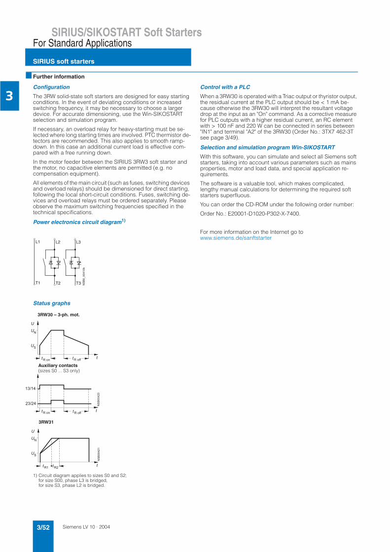
Siemens LV 10 · 20043/52
SIRIUS/SIKOSTART Soft Starters
SIRIUS soft starters
For Standard Applications
3
Further information
Configuration
The 3RW solid-state soft starters are designed for easy starting conditions. In the event of deviating conditions or increased switching frequency, it may be necessary to choose a largerdevice. For accurate dimensioning, use the Win-SIKOSTARTselection and simulation program.
If necessary, an overload relay for heavy-starting must be se-lected where long starting times are involved. PTC thermistor de-tectors are recommended. This also applies to smooth ramp-down. In this case an additional current load is effective com-pared with a free running down.
In the motor feeder between the SIRIUS 3RW3 soft starter and the motor, no capacitive elements are permitted (e.g. nocompensation equipment).
All elements of the main circuit (such as fuses, switching devices and overload relays) should be dimensioned for direct starting, following the local short-circuit conditions. Fuses, switching de-vices and overload relays must be ordered separately. Please observe the maximum switching frequencies specified in the technical specifications.
Power electronics circuit diagram1)
Status graphs
Control with a PLC
When a 3RW30 is operated with a Triac output or thyristor output, the residual current at the PLC output should be < 1 mA be-cause otherwise the 3RW30 will interpret the resultant voltage drop at the input as an "On" command. As a corrective measure for PLC outputs with a higher residual current, an RC element with > 100 nF and 220 W can be connected in series between "IN1" and terminal "A2" of the 3RW30 (Order No.: 3TX7 462-3T see page 3/49).
Selection and simulation program Win-SIKOSTART
With this software, you can simulate and select all Siemens soft starters, taking into account various parameters such as mains properties, motor and load data, and special application re-quirements.
The software is a valuable tool, which makes complicated, lengthy manual calculations for determining the required soft starters superfluous.
You can order the CD-ROM under the following order number:
Order No.: E20001-D1020-P302-X-7400.
For more information on the Internet go towww.siemens.de/sanftstarter
1) Circuit diagram applies to sizes S0 and S2; for size S00, phase L3 is bridged,for size S3, phase L2 is bridged.
L1
NS
B0_
0041
0b
L2 L3
T1 T2 T3
48 433
48 433
Auxiliary contacts(sizes S0 ... S3 only)
3RW30 – 3-ph. mot.
3RW31

Siemens LV 10 · 2004 3/53
SIRIUS/SIKOSTART Soft StartersFor Standard Applications
SIKOSTART soft starters
3
Overview
SIKOSTART 3RW34
Just as easily as with the SIRIUS soft starters, three-phase asyn-chronous motors with rated operating power of up to 1000 kW (at 400 V) can be controlled with SIKOSTART 3RW34. Soft start-ing and soft deceleration are standard functions of this device. Fast commissioning, small sizes and simple installation are the key benefits here.
The devices can be operated with two different contact se-quences:• Inline circuit• Inside-delta circuit
Area of application
The 3RW34 solid-state soft starters are suitable for soft starting and stopping of three-phase asynchronous motor.
Service range
Pumps, compressors, conveyors, and much more.
Functions
• Soft starting with voltage ramp; the starting voltage adjustment range Us is 30 % to 80 % and the ramp time tR can be set from 0.5 s to 60 s.
• Smooth ramp-down with voltage ramp; the running down time toff can be set between 0.5 s to 60 s. Whereby the switch-off voltage Uoff is dependent on the selected starting voltage Us.
• Setting with three potentiometers• Simple mounting and commissioning• Mains voltages at 50/60 Hz 200 V to 600 V• Three control voltage variants for DC 24 V, AC 115 V and
AC 230 V• Extended temperature range: 0 ... +60 °C
Technical specifications
1) The rated motor current (specified on the motor's name plate) should amount to at least 4 % of the SIKOSTART unit's rated current Ie.
2) If this value is exceeded, problems with line capacities may arise, which can result in false firing.
Type 3RW34 ..-0DC2. 3RW34 ..-0DC3. 3RW34 ..-0DC4.Control electronicsRated control supply voltage X1/X2 V 24 DC +10 %/-15 % 115 V AC +10 %/-15 % 230 V AC +10 %/-15 %
Rated frequency Hz - Operating range 45 ... 66
Operating indications (continuous light)
LED 1 ReadyLED 2 Starting terminated
Interference/status indication LED 1 Missing phaseFlash mode 1 (flashing frequency 2 ... 3 Hz)
LED 2 Starting/running down
Fault indications LED 1 EEPROM parity faultFlash mode 2 (flashing frequency 2 ... 3 Hzwith 1 s pause)
LED 2 Thyristor fault or no load connected
Control input Input 1 A1/A2 ON
Control outputs Output 1 13/14 Status indication (NO)Output 2 27/28 Starting end indication (NO)Output 3 37/38 Group fault signal (parameterizable via SW1)
Current-carrying capacity of the control outputs 230 V/AC-15 A 1.0(solid-state) 24 V/DC-13 A 0.5
Type 3RW34 ..-0DC.4 3RW34 ..-0DC.5Power electronicsOperating range for inline circuitRated voltage V 200 ... 460 (-15 %/+10%) 400 ... 600 (-15 %/+10%)
Operating range for inside-delta circuitRated voltage V 200 ... 400 (-15 %/+10%) 400 ... 600 (-15 %/+10%)
Rated frequency Hz Operating range 45 ... 66
Continuous operation at 40° C (% of Ie) % 115100 (for 3RW34 84 and 3RW34 86)
Max. starting time for starting current (% of Ie) To determine the best contactor for your application,Siemens recommends use of Win-SIKOSTART. (Order No. E2001-D1020-P302-X7400).This program is also contained on the CA01.
Minimum load1) (% of Ie) % 4
Permissible ambient temperature Operation °C 0 ... +60 (derating from 40 °C, see load rating)Storage °C 0 ... +70
Permissible installation altitude up to 3 000 m above sea level over 1000 m above sea level linear reduction of Ie, thus at 2000 m above sea level 0.87 x Ie and at 3000 m above sea level 0.77 x Ie
Mounting position The soft starters have been designed for operation on a verticalmounting surface (+12°/-12°).
Maximum conductor length between soft starter and motor m 3002)
Degree of protection IP20 (connection terminals IP00)

Siemens LV 10 · 20043/54
SIRIUS/SIKOSTART Soft Starters
SIKOSTART soft starters
For Standard Applications
3
1) The rated operating current in the inline circuit is specified.
1) The rated operating current in the inline circuit is specified.
2) The busbars must not be connected directly to the soft starter. Flexible busbar connection pieces must be used for the connection.
Type 3RW34 54 3RW34 55 3RW34 57 3RW34 58 3RW34 65 3RW34 66
Load rating
A 57/42/35 70/57/42 110/81/57 135/110/81 162/135/110 195/162/135Rated operating current Ie1) at 40/50/60 °C, AC-53a
Power loss at rated operating current (40 °C) approx. W 158 190 306 358 493 515
Permissible starts per hour for intermittent duty S4 Tu = 40 °C ON-period = 30 % and 300 % x Ie for 10 s
1/h 20
Conductor cross-sections
Screw-type terminals Main conductors(1 or 2 conductor connections)for standard screw driversize 2 and Pozidriv 2
• Stranded mm2 95 120 150 240
Auxiliary conductors
• Solid mm2 2 x (0.5 ... 1.5); 2 x (0.75 ... 2.5) accord. to IEC 60947; max. 2 x (0.75 ... 4)• Finely stranded
with end sleevemm2 2 x (0.5 ... 1.5); 2 x (0.75 ... 2.5)
• AWG conductors,solid or stranded AWG 2 x (18 ... 14)
• Terminal screws M 3- Tightening torque Nm 0.8 ... 1.2 (7 ... 10.3 lb.in)
Rated control supply currents Control inputs DC 24 V mA approx. 45
AC 230 V mA approx. 13
Fans DC 24 V mA approx. 400 approx. 200AC 230 V mA approx. 200 approx. 140
Type 3RW34 67 3RW34 72 3RW34 83 3RW34 84 3RW34 86
Load ratingA 235/195/162 352/285/235 500/450/352 700/608/500 1050/865/726Rated operating current Ie
1) at 40/50/60 °C, AC-53a
Power loss at rated operating current (40 °C) approx. W 629 1023 1425 2020 2949
Permissible starts per hour for intermittent duty S4 Tu = 40 °C ON-period = 30 % and 300 % x Ie for 10 s
1/h 20
Conductor cross-sections
Screw-type terminals Main conductors(1 or 2 conductor connections)for standard screw driversize 2 and Pozidriv 2
• Stranded mm2 240
Auxiliary conductors
• Solid mm2 2 x (0.5 ... 1.5); 2 x (0.75 ... 2.5) accord. to IEC 60947; max. 2 x (0.75 ... 4)• Finely stranded
with end sleevemm2 2 x (0.5 ... 1.5); 2 x (0.75 ... 2.5)
• AWG conductors,solid or stranded AWG 2 x (18 ... 14)
• Terminal screws M 3- Tightening torque Nm 0.8 ... 1.2 (7 ... 10.3 lb.in)
Connecting busbar2) - 40 x 10 50 x 20
Rated control supply currents Control inputs DC 24 V mA approx. 45
AC 230 V mA approx. 13
Fans DC 24 V mA approx. 200 approx. 450 approx. 700AC 230 V mA approx. 140 approx. 280 approx. 420

Siemens LV 10 · 2004 3/55
SIRIUS/SIKOSTART Soft StartersFor Standard Applications
SIKOSTART soft starters
3
Is an RI suppression filter necessary?
1) Busbar connection: L x W x H
Contact address:The suppression filters mentioned above can be ordered fromEPCOS AG (see Appendix –> External Partners).
Radio interference suppressionStandard Parameters
Noise immunity Electrostatic discharge (ESD) IEC 61000-4-2,
EN 60947-4-2Pulse shape: 1/60 ns Test severity 6 kV or 8 kV 4 kV charging voltage in the event of contact discharge 8 kV charging voltage in the event of air discharge
Electromagnetic RF fields IEC 61000-4-3, EN 60647-4-2
Frequency range: 80 MHz ... 1000 MHz with 80 % at 1 kHz field strength 10 V/m
Conducted low-frequency interference (harmonics)
IEC 60 947-4-2 Frequency range: 50 Hz... 10 kHz
RF-voltages and RF-currents onconductors
IEC 61000-4-6, EN 60947-4-2
Frequency range: 80 MHz ...1000 MHz with 80 % at 1 kHz 10 V at 0.15 MHz ... 80 MHz
Burst IEC 61000-4-4 Test severity: 2 kV or 1 kV
Surge IEC 61000-4-5 Test severity: 2 kV or 1 kV
Emitted interference Radio interference field strength CISPR 11/09.1990
EN 60947-4-2
H field: 150 kHz ... 30 MHz E field: 30 MHz ... 1000 MHzlimit value of Class B at 30 MHz ... 1000 MHz
Radio interference voltage CISPR 11/09.1990 EN 60947-4-2
Frequency range: 9 kHz ... 30 MHz(0.15 MHz ... 30 MHz): Unit Class A (industry)and unit Class B (public networks)
Example connections
Inline circuit Inside-delta circuit
430<02012
/545801231218?1<721<<548
;50?@589/1%5?1<3422401?0548
4042
A
430<02012
/545801231218?1<721<<548
;50?@589/1%5?1<3422401?0548
4042
24 V DC control voltage 230 V AC control voltage
Main circuit Control circuit Main circuit Control circuit
Degree of noise suppression A (industrial applications)
No No No No
Degree of noise suppression B(applications for residential areas)
Yes(see table of recommended filters)
No Yes(see table of recommended filters)
No
Soft starter type Rated currentsoft starter
Recommended filtersVoltage range 200 ... 460 V Voltage range 460 ... 600 V
Filter type Rated current filter
Connectionterminals
Filter type Rated current filter
Connection terminals
A A mm2 A mm2
3RW34 54 57 B84143-G66-R110 66 25 B84143-A80-R21 80 253RW34 55 70 B84143-G66-R110 66 25 B84143-A80-R21 80 253RW34 57 110 B84143-G120-R110 120 50 B84143-A120-R21 120 503RW34 58 135 B84143-G150-R110 150 50 B84143-A150-R21 150 503RW34 65 162 B84143-G220-R110 220 95 B84143-A180-R21 180 953RW34 66 195 B84143-G220-R110 220 95 B84143-B250-S21 250 40 x 25 x 51)3RW34 67 235 B84143-G220-R110 220 95 B84143-B250-S21 250 40 x 25 x 51)
3RW34 72 352 B84143-B400-S20 400 40 x 25 x 51) B84143-B400-S21 400 40 x 25 x 51)
3RW34 83 500 B84143-B600-S20 600 40 x 30 x 51) B84143-B600-S21 600 40 x 30 x 51)
3RW34 84 700 B84143-B1000-S20 1000 50 x 40 x 81) B84143-B1000-S21 1000 50 x 40 x 81)
3RW34 86 1050 B84143-B1000-S20 1000 50 x 40 x 81) B84143-B1000-S21 1000 50 x 40 x 81)

Siemens LV 10 · 20043/56
SIRIUS/SIKOSTART Soft Starters
SIKOSTART soft starters
For Standard Applications
3
Circuit examples
Inline circuit
The all-range fuse F’1 (semiconductor and conductor protec-tion) and semiconductor protection F3 must be selected with the aid of the fuse assignment table.
Inside-delta circuit
Important: When the inside-delta circuit is used, the sequence of the terminals must be precisely observed.
1) Optional.
2) For SENTRON 3VL/3WL order number extension, see Circuit-breakers–> Circuit-breakers up to 500 A –> Compact (MCCB) SENTRON VL –> For motor/generator protection ETU.
3) See notes on low-voltage fuse links under Switch-disconnectors and fuses –> Fuses and fuse systems –> Low-voltage fuses.
Soft starter type Rated current Fuse, lead fuse Line contactor acc. to AC-31)
Overload relay Circuit-breaker for motor protection 2)
Power electronics and bridging con-tactor acc. to AC-11)
thermal electronic
F1 K1 F2 F2 Q1 K2A (type 1 coordina-
tion)Recommended motor feedersin inline circuit3RW34 54 57 3NA3 022 3RT10 36 3RU11 46 3RB10 46 3RV10 41 3RT10 353RW34 55 70 3NA3 024 3RT10 45 3RU11 46 3RB10 56 3RV10 41 3RT10 443RW34 57 110 3NA3 032 3RT10 54 - 3RB10 56 3VL27 16-. AP 3RT10 463RW34 58 135 3NA3 036 3RT10 55 - 3RB10 56 3VL27 16-. AP 3RT14 463RW34 65 162 3NA3 140 3RT10 56 - 3RB10 56 3VL37 20-. AP 3RT14 563RW34 66 195 3NA3 140 3RT10 64 - 3RB10 56 3VL37 25-. AP 3RT14 563RW34 67 235 3NA3 144 3RT10 65 - 3RB10 66 3VL37 25-. AP 3RT14 563RW34 72 352 3NA3 2543) 3RT10 75 - 3RB10 66 3VL47 40-. AP 3RT14 663RW34 83 500 3NA3 365 3TF68 - 3RB10 66 3VL57 50-. AP 3RT14 763RW34 84 700 3NA3 475 3TF69 - 3RB12 62 3WL11 08-.EB 3RT14 763RW34 86 1050 3NA3 482 2 x 3TF68
(parallel)- - 3WL11 12-.EB 2 x 3TF68
(parallel)Recommended motor feeders in inside-delta circuit3RW34 54 99 3NA3 032 3RT10 44 3RU11 46 3RB10 46 3VL27 16-.AP 3RT10 353RW34 55 121 3NA3 036 3RT10 45 3RU11 46 3RB10 46 3VL27 16-.AP 3RT10 443RW34 57 191 3NA3 142 3RT10 54 3UA6. 01 3RB12 53 3VL37 25-.AP 3RT10 463RW34 58 234 3NA3 144 3RT10 55 3UA61 01 3RB12 53 3VL37 25-.AP 3RT14 463RW34 65 281 3NA3 252 3RT10 56 3UA62 01 3RB12 53 3VL47 31-.AP 3RT14 563RW34 66 338 3NA3 2543) 3RT10 64 3UA62 01 3RB12 53 3VL47 40-.AP 3RT14 563RW34 67 407 3NA3 365 3RT10 65 - 3RB12 57 3VL57 63-.AP 3RT14 563RW34 72 610 3NA3 472 3RT10 75 - 3RB12 57 3VL57 63-.AP 3RT14 663RW34 83 866 3NA3 480 3TF68 - 3RB12 57 3WL12 10-.EB 3RT14 763RW34 84 1212 3NA3 682 3TF69 - 3RB12 62 3WL12 12-.EB 3RT14 763RW34 86 1819 - 2 x 3TF68
(parallel)- - 3WL12 20-.EB 2 x 3TF68
(parallel)

Siemens LV 10 · 2004 3/57
SIRIUS/SIKOSTART Soft StartersFor Standard Applications
SIKOSTART soft starters
3
1) E.g. 3x Ie for 60 s.
2) E.g. 3x Ie for 30 s.
3) The types of coordination are explained in more detail under Load Feeders > Fuseless Load Feeders.
4) No direct connection to busbars.
1) E.g. 3x Ie for 60 s.
2) E.g. 3x Ie for 30 s.
3) The types of coordination are explained in more detail under Load Feeders > Fuseless Load Feeders.
4) No direct connection to busbars.
Note:All selection data refer to inline circuits.For selections for the inside-delta-circuit, please contact techni-cal support.
Further information is available on the Internet at:www.siemens.com/softstarter.
Fuse assignmentFuse design with 3NE1 SITOR fuses with full utilization1) of the soft starter(semiconductor and lead protection)
Fuse design with 3NE3 SITOR fuses with full utilization1) of the soft starter, lowest possible protection, age-free (semiconductor protection)
Fuse design with 3NE3 SITOR fuses with full utilization1) of the soft starter, highest possible protection, age-free (semiconductor protection)
Soft starter All-range fuse F'1 Semiconductor fuse F3 Semiconductor fuse F3
Type Type Rated current
Size Requiredconductorcross-section for each fuse
Type Rated current
Size Type Rated current
Size
A mm2 A A
Type of coordination 23): Iq = 50 kA at 400 V
3RW34 54-0DC.4 3NE1 021-0 100 00 35 3NE3 222 125 1 3NE3 225 200 13RW34 55-0DC.4 3NE1 022-0 125 00 50 3NE3 224 160 1 3NE3 231 350 13RW34 57-0DC.4 3NE1 225-0 200 1 95 3NE3 225 200 1 3NE3 233 450 13RW34 58-0DC.42) 3NE1 227-0 250 1 120 3NE3 227 250 1 3NE3 333 450 23RW34 65-0DC.4 3NE1 230-0 315 1 2 x 70 3NE3 230-0B 315 1 3NE3 334-0B 500 23RW34 66-0DC.4 3NE1 230-0 315 1 2 x 70 3NE3 231 350 1 3NE3 336 630 23RW34 67-0DC.4 3NE1 332-0 400 2 2 x 95 3NE3 233 450 1 3NE3 340-8 900 23RW34 72-0DC.4 3NE1 435-0 560 3 2 x 150 3NE3 336 630 2 3NE3 340-8 900 23RW34 83-0DC.4 3NE1 438-0 800 3 2 x (50 x 5)4) 3NE3 340-8 900 2 3NE3 340-8 900 23RW34 84-0DC.4 2 x 3NE1 435-0 2 x 560 3 2 x 150 2 x 3NE3 336 2 x 630 2 2 x 3NE3 340-8 2 x 900 23RW34 86-0DC.42) 2 x 3NE1 437-1 2 x 710 3 2 x (40 x 5)4) 2 x 3NE3 340-8 2 x 900 2 2 x 3NE3 340-8 2 x 900 2
Fuse design with 3NE1 SITOR fuses with full utilization1) of the soft starter(semiconductor and lead protection)
Fuse design with 3NE3 SITOR fuses with full utilization1) of the soft starter, lowest possible protection, age-free (semiconductor protection)
Fuse design with 3NE3 SITOR fuses with full utilization1) of the soft starter, highest possible protection, age-free (semiconductor protection)
Soft starter All-range fuse F'1 Semiconductor fuse F3 Semiconductor fuse F3
Type Type Rated current
Size Required con-ductor cross-section for each fuse
Type Rated current
Size Type Rated current
Size
A mm2 A A
Type of coordination 23): Iq = 50 kA at 575 V
3RW34 54-0DC.5 3NE1 022-2 125 00 50 3NE3 222 125 1 3NE3 225 200 13RW34 55-0DC.5 3NE1 022-0 125 00 50 3NE3 224 160 1 3NE3 230-0B 315 13RW34 57-0DC.5 3NE1 225-0 200 1 95 3NE3 225 200 1 3NE3 233 415 13RW34 58-0DC.52) 3NE1 225-0 200 1 95 3NE3 227 250 1 3NE3 333 450 23RW34 65-0DC.5 3NE1 227-0 250 1 120 3NE3 230-0B 315 1 3NE3 334-0B 500 23RW34 66-0DC.5 3NE1 230-0 315 1 2 x 70 3NE3 231 350 1 3NE3 336 630 23RW34 67-0DC.5 3NE1 332-0 400 2 2 x 95 3NE3 233 450 1 3NE3 340-8 900 23RW34 72-0DC.5 3NE1 435-2 560 3 2 x 150 3NE3 336 630 2 3NE3 340-8 900 23RW34 83-0DC.5 3NE1 437-0 710 3 2 x (40 x 5)4) 3NE3 340-8 900 2 3NE3 340-8 900 23RW34 84-0DC.5 2 x 3NE1 435-0 2 x 560 3 2 x 150 2 x 3NE3 336 2 x 630 2 2 x 3NE3 340-8 2 x 900 23RW34 86-0DC.52) 2 x 3NE1 437-2 2 x 710 3 2 x (40 x 5)4) 2 x 3NE3 340-8 2 x 900 2 2 x 3NE3 340-8 2 x 900 2

Siemens LV 10 · 20043/58
SIRIUS/SIKOSTART Soft Starters
SIKOSTART soft starters
For Standard Applications
3
* This quantity or a multiple thereof can be ordered.
Selection and ordering data
1) In the selection table, the unit rated operating current refers to the motor's rated operating current in the inside-delta circuit.The actual current of the unit is approx. 58 % of this value.
2) SIKOSTART 3RW34 86-0DC..: not available as DC 24 V design.3) SIKOSTART 3RW34 57-0DC.. and 3RW34 86-0DC..:
not available as DC 115 V design.4) The specified hp values apply to 50 Hz networks. In conjunction with
60 Hz networks, in the AC 115 V design, a higher motor hp is possible. Relevant values on request.
5) The delivery times apply to AC 230 V soft starters. Delivery times for the remaining designs on request.
Soft starter selection depends on the motor’s rated current.The 3RW34 solid-state starters are designed for normal starting. In the event of deviating conditions or increased switching fre-quency, it may be necessary to choose a larger unit. Siemens recommends the use of the selection and simulation program Win-SIKOSTART. See technical specifications for information about rated currents for ambient temperatures >40 °C.
Ratedoperating voltage Ue
At ambient temperature 40 °C At ambient temperature 50 °C DT5)
Order No. PS* Weight per PU approx.
Rated operat-ing currentIe
1)
Rated output of three-phase motors for rated operating voltage Ue
Rated operat-ing currentIe
1)
Rated output of three-phase motors for rated operating voltage Ue
230 V 400 V 500 V 200 V 230 V 460 V 575 V
V A kW kW kW A hp hp hp hp kgInline circuit200 ... 460 57 15 30 - 42 10 15 30 - A 3RW34 54-0DC@4 1 unit 8.460
70 18.5 37 - 57 15 20 40 - 3RW34 55-0DC@4 1 unit 10.000110 30 55 - 81 25 30 60 - A 3RW34 57-0DC@4 1 unit 9.900135 37 75 - 110 30 40 75 - A 3RW34 58-0DC@4 1 unit 9.870
162 45 90 - 135 40 50 100 - A 3RW34 65-0DC@4 1 unit 19.000195 55 110 - 162 50 60 125 - A 3RW34 66-0DC@4 1 unit 19.100235 75 132 - 195 60 75 150 - A 3RW34 67-0DC@4 1 unit 21.100
352 110 200 - 285 100 100 200 - A 3RW34 72-0DC@4 1 unit 36.300
500 160 250 - 450 150 150 350 - A 3RW34 83-0DC@4 1 unit 59.600700 200 400 - 608 200 250 500 - A 3RW34 84-0DC@4 1 unit 59.6001050 315 560 - 865 300 350 750 - D 3RW34 86-0DC@4 1 unit 95.100
400 ... 600 57 - 30 37 42 - - 30 40 C 3RW34 54-0DC@5 1 unit 8.60070 - 37 45 57 - - 40 50 C 3RW34 55-0DC@5 1 unit 10.000110 - 55 75 81 - - 60 75 C 3RW34 57-0DC@5 1 unit 9.480135 - 75 90 110 - - 75 100 C 3RW34 58-0DC@5 1 unit 7.650
162 - 90 110 135 - - 100 125 C 3RW34 65-0DC@5 1 unit 15.000195 - 110 132 162 - - 125 150 C 3RW34 66-0DC@5 1 unit 15.000235 - 132 160 195 - - 150 200 C 3RW34 67-0DC@5 1 unit 21.100
352 - 200 250 285 - - 200 300 C 3RW34 72-0DC@5 1 unit 37.000
500 - 250 355 450 - - 350 450 C 3RW34 83-0DC@5 1 unit 59.600700 - 400 500 608 - - 500 700 C 3RW34 84-0DC@5 1 unit 59.6001050 - 560 710 865 - - 750 1000 D 3RW34 86-0DC@5 1 unit 95.100
Inside-delta circuit200 ... 400 99 30 55 - 73 20 25 - - A 3RW34 54-0DC@4 1 unit 8.460
121 37 55 - 99 30 30 - - 3RW34 55-0DC@4 1 unit 10.000191 55 110 - 140 40 50 - - A 3RW34 57-0DC@4 1 unit 9.900234 75 132 - 191 60 60 - - A 3RW34 58-0DC@4 1 unit 9.870
281 90 160 - 234 75 75 - - A 3RW34 65-0DC@4 1 unit 19.000338 110 200 - 281 100 100 - - A 3RW34 66-0DC@4 1 unit 19.100407 132 250 - 338 100 125 - - A 3RW34 67-0DC@4 1 unit 21.100
610 200 355 - 494 150 200 - - A 3RW34 72-0DC@4 1 unit 36.300
866 250 500 - 779 250 300 - - A 3RW34 83-0DC@4 1 unit 59.6001212 400 710 - 1053 350 450 - - A 3RW34 84-0DC@4 1 unit 59.6001819 560 1000 - 1498 600 650 - - D 3RW34 86-0DC@4 1 unit 95.100
400 ... 600 99 - 55 55 73 - - 50 75 C 3RW34 54-0DC@5 1 unit 8.600121 - 55 75 99 - - 75 100 C 3RW34 55-0DC@5 1 unit 10.000191 - 110 132 140 - - 100 150 C 3RW34 57-0DC@5 1 unit 9.480234 - 132 160 191 - - 150 200 C 3RW34 58-0DC@5 1 unit 7.650
281 - 160 200 234 - - 200 250 C 3RW34 65-0DC@5 1 unit 15.000338 - 200 250 281 - - 200 300 C 3RW34 66-0DC@5 1 unit 15.000407 - 250 315 338 - - 250 350 C 3RW34 67-0DC@5 1 unit 21.100
610 - 355 400 494 - - 400 500 C 3RW34 72-0DC@5 1 unit 37.000
866 - 500 630 779 - - 700 850 C 3RW34 83-0DC@5 1 unit 59.6001212 - 710 800 1053 - - 950 1200 C 3RW34 84-0DC@5 1 unit 59.6001819 - 1000 1200 1498 - - 1300 1700 D 3RW34 86-0DC@5 1 unit 95.100
Order No. extension for rated control supply voltage Us
DC 24 V2) 2AC 115 V3)4) 3AC 230 V 4

Siemens LV 10 · 2004 3/59
SIRIUS/SIKOSTART Soft StartersFor Standard Applications
SIKOSTART soft starters
3
Accessories
Spare parts
For soft starters Version DT Order No. PS* Weight per PU approx.
kgTerminal covers
3KX3 552–3DA01
3RW34 543RW34 553RW34 573RW34 58
Terminal cover(1 set = 6 units)M 6 terminal screws
3KX3 552-3DA01 1 set 0.077
Operating instructionsInstruction manuals for SIKOSTART 3RW34 .. in
- German B 3ZX1012-0RW34-1AN1 1 unit 0.010- English- Italian- French- Spanish- Portuguese
are available in Adobe Acrobat format free-of-charge on the Internet at www.siemens.de/automation/manuals. Enter “SIKOSTART manuals” or “3RW34 manuals” as search term.
For soft starters Maximum number required per device DT Order No. PS* Weight per PU approx.
Type kgControl unit
3RW34 ..-0DC2. 1 3RW39 50-6DC28 1 unit 0.5653RW34 ..-0DC3. 1 A 3RW39 50-6DC38 1 unit 0.3243RW34 ..-0DC4. 1 A 3RW39 50-6DC48 1 unit 0.348
Fans3RW34 5.-0DC2. 2 X 3RW39 50-8DC28 1 unit 0.2613RW34 5.-0DC4. 2 A 3RW39 50-8DC48 1 unit 0.6483RW34 6.-0DC2. 1 X 3RW39 60-8DC28 1 unit 0.600
3RW34 6.-0DC4. 3RW34 72-0DC4. 3RW34 8.-0DC4.
123
3RW39 60-8DC48 1 unit 0.685
3RW34 72-0DC2. 2 X 3RW39 70-8DC28 1 unit 0.6163RW34 83-0DC2. 3RW34 84-0DC2.
33
X 3RW39 72-8DC28 1 unit 0.558
3RW34 84-0DC2. 3 X 3RW39 73-8DC28 1 unit 0.600
* This quantity or a multiple thereof can be ordered.

Siemens LV 10 · 20043/60
SIRIUS/SIKOSTART Soft Starters
SIKOSTART soft starters
For Standard Applications
3
Circuit diagrams
1) With SW1-4, the fault contact can be switched over between normally closed and normally open.
Connection examples for main and control circuitsMain circuitPossibility 1: inline circuit
Control circuitPossibility 1: control via pushbutton
Main circuit Phase switchingPossibility 2: inside-delta circuit for inside-delta circuit
Control circuitPossibility 2: control via switch
Main circuitPossibility 3: inline circuit with bypass contactor
Control circuitPossibility 3: control via switch plus bypass contactor
! " # " $ % % % & % ! # & # ' &
" $ % ! # $ ( & ( % ) " & ) * " #
+ ,
+
-
% .
% . + % ,
% . + %
/
0
/
1
1
2
2
3
3
4
/
/
,
2 * 5 " 6 " & 7 %
6 # 8 '
2 #
2 ) 9 $ : 6 ' ( 8 ' ; ' $ #
/ $
; < * < % $ (
' ! ! 8 '
2 ) 9 $ : 6 ' ( 8 ' ; ' $ #
* 6 # % % =
>
! " # " $ % % % & % ! # & # ' &
" $ % " $ ! " ( ' ( ' 6 # % ) " & ) * " #
* 6 # % % =
+ ,
+
-
% .
% . + % ,
% .+ %
/
0
/
1
1
2
2
3
3
4
,
2 * 5 " 6 " & 7
6 # 8 '
2 #
2 ) 9 $ : 6 ' ( 8 ' ; ' $ #
/ $
; < * < % $ (
' ! ! 8 '
2 ) 9 $ : 6 ' ( 8 ' ; ' $ #
! " # " $ % % % & % ! # & # ' &
" $ % ! # $ ( & ( % ) " & ) * " #
: " # ? % 7 < ! ! % ) $ # ) # &
+ ,
+
-
% .
% . + % ,
% . + %
/
0
/
1
1
2
2
3
3
4
,
2 * 5 " 6 " & 7
6 # 8 '
2 #
2 ) 9 $ : 6 ' ( 8 ' ; ' $ #
/ $
; < * < % $ (
' ! ! 8 '
7 < ! !
) $ # ) # & 2 ) 9 $ : 6 ' ( 8 ' ; ' $ #
* 6 # % % % =

Siemens LV 10 · 2004 3/61
SIRIUS/SIKOSTART Soft StartersFor Standard Applications
SIKOSTART soft starters
3
Further information
Configuration
The 3RW34 solid-state starters are designed for normal starting. In the event of deviating conditions or increased switching fre-quency, it may be necessary to choose a larger unit. For accu-rate dimensioning, use the Win-SIKOSTART selection and simu-lation program.
If necessary, an overload relay for heavy-starting must be se-lected where long starting times are involved. PTC thermistor de-tectors are recommended. This also applies to soft running down. In this case an additional current load is effective com-pared with a free ramp-down.
In the motor feeder between the SIKOSTART and the motor, no capacitive elements are permitted (e.g. no compensation equip-ment).
All elements of the main circuit (such as fuses, switching devices and overload relays) should be dimensioned for direct starting, following the local short-circuit conditions. Fuses, switching de-vices and overload relays must be ordered separately.
Circuit concept
The SIKOSTART 3RW34 can be operated in two different types of circuit.• Inline circuit
The switching devices for isolating and protecting the motor are simply connected in series with the soft starter. The motor is connected to the soft starter with three leads.
• Inside-delta circuitThe wiring is similar to that of star-delta starters. The phases of the soft starter are connected in series with the individual motor windings. The soft starter then only has to carry the phase cur-rent, amounting to about 58 % of the rated current of the motor (conductor current).
Comparison of the types of circuit
Inline circuit:Rated current Ie corresponds to the rated motor current In,3 conductors to motor
Inside-delta circuit:Rated current Ie corresponds to approx. 58 % of the rated motor current In,6 conductors to motor (as star delta starters)
Which circuit?
Using the inline circuit involves the lowest wiring complexity, which is twice as high when using the inside-delta circuit. If the soft starter to motor connections are short, this contact se-quence is preferable.
Thanks to the possibility of switching between the inline circuit and inside-delta circuit, the most favorable solution can always be chosen.
Settings
DIP switches (SW1):
This switch is located on the main logic module. It is used for set-ting the soft starter software to the relevant application.
1)SW1-1: causes an OFF delay on the soft starter. The OFF delay is required when using a parallel contactor (bridging contac-tor). It initially enables the contactor to be deenergized, after which the soft starter switches 1.0 s later. This prevents dam-age to the thyristors from voltage peaks which arise when the bridging contactor interrupts the motor current.
2)SW1-2: Sets an ON delay signal for the soft starter. This func-tion makes it possible for a contactor disconnector first to be switched on in the currentless state, with the soft starter then being switched 1.0 s later. This has the effect of increasing the life of the contacts of the contactor disconnector.
3)SW1-3: Sets the soft starter software for operation with thyris-tors in the inline circuit or within the inside-delta circuit.
4)SW1-4: Sets the fault contact as an NO contact or NC contact. This contact can be used for controlling a fault contactor, a shunt release or a fault alarm.

Siemens LV 10 · 20043/62
SIRIUS/SIKOSTART Soft Starters
SIKOSTART soft starters
For Advanced Applications
3
Overview
SIKOSTART 3RW22
In addition to soft starting and soft ramp-down, the solid-state SIKOSTART 3RW22 soft starters provide numerous functions for higher-level requirements They cover a rating range of up to 710 kW (at 400 V).
Combinations of various starting, operating and ramp-down possibilities ensure an optimum adaptation to the application-specific requirements. Operation and commissioning can be carried out either conventionally with switches and potentiome-ters or conveniently using a commercial PC and an RS232 inter-face.
Applicable standards • IEC 60947-4-2• UL/CSA for 3RW22 21 to 3RW22 31
Area of application
The SIKOSTART 3RW22 solid-state soft starters are suitable for the controlled soft starting and ramp-down, for the braking and the energy-saving operation of three-phase induction motors.
Applications• Pumps, compressors• Fans, blowers• Conveyors• Breakers, mills• Agitators• Sanding machines• Wire drawing/textile machines• Presses• Machine tools
Functions
• Soft starting with breakaway pulse, voltage ramp, voltage or current limiting as well as any combination of these, depending on load type
• Varied setting facilities for the starting parameters as starting voltage, ramp time etc.
• Start-up detection• Energy saving mode• Four running-down modes selectable: free ramp-down,
pump stopping, soft stop, DC braking• Electronic overload protection• Protection against temperature rise• Parameters can be set via a potentiometer and sliding-dolly
switch or using the PC program COM SIKOSTART• Interface for communication with the PC for more accurate set-
ting of the parameters as well as for control and monitoring• Simple adaptation to the motor feeder• Simple mounting and commissioning• Display of 5 operating states and 5 fault signals• System voltages from 200 V to 1000 V, 50/60Hz• Integrated power supply unit for three control supply
voltages• Applicable up to 55 °C• Higher load ratings by selecting low ambient temperatures.

Siemens LV 10 · 2004 3/63
SIRIUS/SIKOSTART Soft StartersFor Advanced Applications
SIKOSTART soft starters
3
Technical specifications
Control electronicsRated control supply voltage (terminal 12 - 15) V 380 ... 415, 200 ... 240, 100 ... 120 (+10 %/-15 %)
Rated frequency Hz 50/60, operating range 45 ... 66
Rated control supply current at 380 V ... 415 V mA approx. 40at 200 V ... 240 V mA approx. 75at 100 V ... 120 V mA approx. 100
Short-circuit protection, control circuit built-in fuse 250 mA slow, 6.3 mm x 32 mm
Operating times ON-delay ms ≤ 50 controlled separately when the control supply voltage is applied andvoltage is present in the control circuit
ON-delay s ≤ 1 contactor operation, ON/OFF by switching the control supply voltageON-delay s ≤ 1.1 automatic modeRecovery time ms ≤ 440 after DC braking
Power failure
Bridging time control supply voltage ms ≤ 80
Response time load current circuit ms ≤ 100
Operating indications (continuous light)
LED 1 ReadyLED 2 starting or slowing downLED 3 starting endedLED 4 energy save mode activeLED 5 braking
Fault indications(flashing light)
LED 1 Mains fault (phase failure, missing voltage/load, control supply voltage too low)
LED 2 Thyristor defective (one or several thyristor(s) alloyed)LED 3 Excess temperature or overload deactivationLED 4 Unit malfunctionLED 5 Unit gets too hot; new starting is inhibited; however, unit continues to operate
Control inputson versions with serial interface, the input assignments are dependent on the number of parameter sets selected via the COM-SIKOSTART PC communication program (up to 3 parameter sets can be selected)
• Standard application:with one motor
Input 1 ON
Input 2 OFF
Input 3 Reset
• Serial starting of several motors or of reversible pole motors
Input 1 ON/OFF parameter set 1
Input 2 ON/OFF parameter set 2
Input 3 Reset or ON/OFF parameter set 3
Rated operating current mA approx. 10 according to DIN 19 240
Rated voltage V DC 24 V from built-in power supply unit via DC +24 V terminal
Relay outputs Output 1 Group fault signal (changeover contact)Output 2 Starting terminated; motor connected to full mains voltage (NO contact)Output 3 DC brakes active; for control of the braking contactor (NO contact)
Rated operating current A 3 AC-15/AC-14 at 240 VA 0.1 DC-13 at 240 VA 0.5 DC-13 at 24 V
Short-circuit protection 4 A utilization category gL/gG; 6 A fast (fuse is not included in scope of supply)
Max. conductor cross-sections • Solid mm2 0.5 ... 2.5• Finely stranded with end
sleevemm2 0.5 ... 1.5
• Tightening torque Nm 0.8 ... 1.4

Siemens LV 10 · 20043/64
SIRIUS/SIKOSTART Soft Starters
SIKOSTART soft starters
For Advanced Applications
3
1) The rated motor current (specified on the motor's rating plate) should amount to at least 20 % of the SIKOSTART unit's rated current Ie.
2) If this value is exceeded, problems with line capacities may arise, which can result in false firing.
Power electronics Continuous operation (% of Ie) % 115
Max. starting time
• cold (40 °C or 55 °C)/warm Starting current
600 % Ie s 2/1450 % Ie s 10/5300 % Ie s 60/30250 % Ie s 120/60200 % Ie s 200/100
Minimum load 1) (% of Ie) % 20
Permissible ambient temperature• in operation °C 0 ... +40 or +55 (switchable)• when stored °C -25 ... +80
Operating range
• Rated operating voltage VVVV
200 (-15 %) ... 500 (+10 %) for 3RW22 ..-0DB15,200 (-15 %) ... 415 (+10 %) for 3RW22 ..-0DB14,500 (-15 %) ... 690 (+10 %) for 3RW22 ..-0DB16,1000 (-20 %; +25 %) for 3RW22 ..-0DB18
• Frequency Hz 45 ... 66
Degree of protectionacc. to IEC 60947-1/IEC 60529
RW22 21 ... RW22 31RW22 34 ... RW22 50
IP20IP00
Overload protection Thermal sensor on the heatsink, solid-state protection with thermal image
Permissible installation altitude up to 3 000 m above sea level; over 1000 m above sea level linear reduction of Ie, thus at 2 000 m above sea level 0.87 x Ie and at 3 000 m above sea level 0.77 x Ie
Fans• Rated control supply voltage V 230 ±10%• Frequency Hz 45 ... 66
Maximum conductor length between soft starter and motor m 2002)
Power electronicsType (200 ... 500 V) 3RW22 21-1AB15 3RW22 23-1AB15 3RW22 25-1AB15 3RW22 26-1AB15
Load rating
Rated operating current Ie at 40/55 °C, AC-3 A 7/5.5 10.5/9 22/16 28/22Motor output (400 V) approx. at 40/55 °C, AC-3 kW 3/2.2 4/4 11/7.5 15/11
Permissible starts per hour for intermittent duty S4, Tu = 40 °CON-period = 30 %
350 % x Ie for 5 s 1/h 80 90 30 20300 % x Ie for 10 s 1/h 50 60 20 10250 % x Ie for 15 s 1/h 50 50 20 10
Power loss at rated operating current (40 °C) approx. W 30 40 70 80
Max. conductor cross-sections • Solid mm² 1 ... 16 1 ... 16 1 ... 16 1 ... 16• Finely stranded without end
sleevemm² 2.5 ... 16 2.5 ... 16 2.5 ... 16 2.5 ... 16
• Finely stranded with end sleeve
mm² 1 ... 16 1 ... 16 1 ... 16 1 ... 16
• Stranded mm² 2.5 ... 25 2.5 ... 25 2.5 ... 25 2.5 ... 25
Bridging contactor for AC-1 3RT10 15 3RT10 15 3RT10 24 3RT10 24(if required, as a main contactor to AC-3) 3RT10 16 3RT10 17 3RT10 26 3RT10 34
Recommended braking contactor 3RT15 1. 3RT15 26 3RT15 26 3RT15 26
Type (200 ... 500 V) 3RW22 27-1AB15 3RW22 28-1AB15 3RW22 30-1AB15 3RW22 31-1AB15
Load rating
Rated operating current Ie at 40/55 °C, AC-3 A 35/32 45/37 50/45 70/63Motor output (400 V) at 40/55 °C, AC-3 kW 18.5/15 22/18.5 25/22 37/30
Permissible starts per hour for intermittent duty S4, Tu = 40 °CON-period = 30 %
350 % x Ie for 5 s 1/h 50 30 20 40300 % x Ie for 10 s 1/h 30 20 20 30250 % x Ie for 15 s 1/h 30 20 20 30
Power loss at rated operating current (40 °C) approx. W 105 130 140 220
Max. conductor cross-sections • Solid mm² 1/16 1/16 1/16 1/16• Finely stranded without end
sleevemm² 2.5 ... 16 2.5 ... 16 2.5 ... 16 2.5 ... 16
• Finely stranded with end sleeve
mm² 1/16 1/16 1/16 1/16
• Stranded mm² 2.5/25 2.5/25 2.5/25 2.5/25
Bridging contactor for AC-1 3RT10 24 3RT10 34 3RT10 35 3RT10 44(if required, as a main contactor to AC-3) 3RT10 35 3RT10 36 3RT10 44 3RT10 45
Recommended braking contactor 3RT15 26 3RT15 26 3RT15 35 3RT15 35
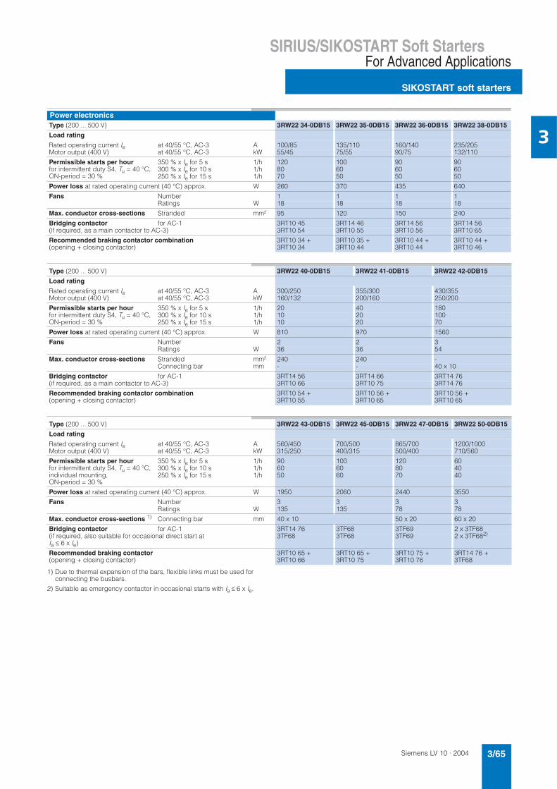
Siemens LV 10 · 2004 3/65
SIRIUS/SIKOSTART Soft StartersFor Advanced Applications
SIKOSTART soft starters
3
1) Due to thermal expansion of the bars, flexible links must be used forconnecting the busbars.
2) Suitable as emergency contactor in occasional starts with Ia ≤ 6 x Ie.
Power electronicsType (200 ... 500 V) 3RW22 34-0DB15 3RW22 35-0DB15 3RW22 36-0DB15 3RW22 38-0DB15
Load rating
Rated operating current Ie at 40/55 °C, AC-3 A 100/85 135/110 160/140 235/205Motor output (400 V) at 40/55 °C, AC-3 kW 55/45 75/55 90/75 132/110
Permissible starts per hour for intermittent duty S4, Tu = 40 °C, ON-period = 30 %
350 % x Ie for 5 s 1/h 120 100 90 90300 % x Ie for 10 s 1/h 80 60 60 60250 % x Ie for 15 s 1/h 70 50 50 50
Power loss at rated operating current (40 °C) approx. W 260 370 435 640
Fans Number 1 1 1 1Ratings W 18 18 18 18
Max. conductor cross-sections Stranded mm² 95 120 150 240
Bridging contactor for AC-1 3RT10 45 3RT14 46 3RT14 56 3RT14 56(if required, as a main contactor to AC-3) 3RT10 54 3RT10 55 3RT10 56 3RT10 65
Recommended braking contactor combination(opening + closing contactor)
3RT10 34 + 3RT10 34
3RT10 35 +3RT10 44
3RT10 44 + 3RT10 44
3RT10 44 + 3RT10 46
Type (200 ... 500 V) 3RW22 40-0DB15 3RW22 41-0DB15 3RW22 42-0DB15
Load rating
Rated operating current Ie at 40/55 °C, AC-3 A 300/250 355/300 430/355Motor output (400 V) at 40/55 °C, AC-3 kW 160/132 200/160 250/200
Permissible starts per hour for intermittent duty S4, Tu = 40 °C, ON-period = 30 %
350 % x Ie for 5 s 1/h 20 40 180300 % x Ie for 10 s 1/h 10 20 100250 % x Ie for 15 s 1/h 10 20 70
Power loss at rated operating current (40 °C) approx. W 810 970 1560
Fans Number 2 2 3Ratings W 36 36 54
Max. conductor cross-sections Stranded mm² 240 240 -Connecting bar mm - - 40 x 10
Bridging contactor for AC-1 3RT14 56 3RT14 66 3RT14 76(if required, as a main contactor to AC-3) 3RT10 66 3RT10 75 3RT14 76
Recommended braking contactor combination(opening + closing contactor)
3RT10 54 + 3RT10 55
3RT10 56 + 3RT10 65
3RT10 56 + 3RT10 65
Type (200 ... 500 V) 3RW22 43-0DB15 3RW22 45-0DB15 3RW22 47-0DB15 3RW22 50-0DB15
Load rating
Rated operating current Ie at 40/55 °C, AC-3 A 560/450 700/500 865/700 1200/1000Motor output (400 V) at 40/55 °C, AC-3 kW 315/250 400/315 500/400 710/560
Permissible starts per hour for intermittent duty S4, Tu = 40 °C, individual mounting, ON-period = 30 %
350 % x Ie for 5 s 1/h 90 100 120 60300 % x Ie for 10 s 1/h 60 60 80 40250 % x Ie for 15 s 1/h 50 60 70 40
Power loss at rated operating current (40 °C) approx. W 1950 2060 2440 3550
Fans Number 3 3 3 3Ratings W 135 135 78 78
Max. conductor cross-sections 1) Connecting bar mm 40 x 10 50 x 20 60 x 20
Bridging contactor for AC-1 3RT14 76 3TF68 3TF69 2 x 3TF68(if required, also suitable for occasional direct start at Ia ≤ 6 x Ie)
3TF68 3TF68 3TF69 2 x 3TF682)
Recommended braking contactor(opening + closing contactor)
3RT10 65 + 3RT10 66
3RT10 65 + 3RT10 75
3RT10 75 + 3RT10 76
3RT14 76 + 3TF68

Siemens LV 10 · 20043/66
SIRIUS/SIKOSTART Soft Starters
SIKOSTART soft starters
For Advanced Applications
3
1) Due to thermal expansion of the bars, flexible links must be used for connecting the busbars.
1) Due to thermal expansion of the bars, flexible links must be used for connecting the busbars.
2) Suitable as emergency contactor in occasional starts with Ia ≤ 6 x Ie.
1) Due to thermal expansion of the bars, flexible links must be used forconnecting the busbars.
Power electronicsType (500 ... 690 V) 3RW22 36-0DB16 3RW22 38-0DB16 3RW22 40-0DB16 3RW22 42-0DB16
Load rating
Rated operating current Ie at 40/55 °C, AC-3 A 160/140 235/205 300/250 450/355Motor output (690 V) at 40/55 °C, AC-3 kW 160/132 250/200 315/250 450/355
Permissible starts per hour 350 % x Ie for 5 s 1/h 90 90 20 180Intermittent duty S4, Tu = 40 °C 300 % x Ie for 10 s 1/h 60 60 10 100ON-period = 30 % 250 % x Ie for 15 s 1/h 50 50 10 70
Short-circuit protection SITOR A 500 630 2 x 500 2 x 560Fuse links Type 3NE3 334-0B 3NE3 336 2 x 3NE3 334-0B 2 x 3NE3 335
Fuse switch disconnector Type 3NP44 73NP54(3NP44 76)
3NP44 73NP54(3NP44 76)
2 x 3NP44 72 x 3NP54(2 x 3NP44 76)
2 x 3NP44 72 x 3NP54(2 x 3NP44 76)
Switch disconnector for fuses Type 3KL613KM57
3KL613KM57
2 x 3KL612 x 3KM57
2 x 3KL612 x 3KM57
Power loss at rated operating current (40 °C) approx. W 490 700 810 1550
Fans Number 1 1 2 3Ratings W 18 18 36 54
Max. conductor cross-sections 1) Stranded mm2 150 240 240 –Connecting bar mm – – – 40 x 10
Bridging contactor for AC-1 3RT14 56 3RT10 56 3RT14 56 3RT10 75
Recommended braking contactor combination(opening + closing contactor)
3RT10 36 +3RT10 54
3RT10 44 +3RT10 46
3RT10 54 +3RT10 56
3RT10 56 + 3RT10 65
Type (500 ... 690 V) 3RW22 43-0DB16 3RW22 47-0DB16 3RW22 50-0DB16
Load rating
Rated operating current Ie at 40/55 °C, AC-3 A 560/450 865/700 1200/1000Motor output (690 V) at 40/55 °C, AC-3 kW 560/450 850/710 1200/1000
Permissible starts per hour for intermittent duty S4, Tu = 40 °C, ON-period = 30 %
350 % x Ie for 5 s 1/h 90 100 60300 % x Ie for 10 s 1/h 60 80 40250 % x Ie for 15 s 1/h 50 70 40
Short-circuit protection SITOR A 2 x 560 3 x 800 4 x 800Fuse links Type 2 x 3NE3 335 3 x 3NE3 338-8 4 x 3NE3 338-8Fuse switch disconnector Type 2 x 3NP44 7
2 x 3NP54 2 x (3NP44 76)
3 x 3NP44 7 3 x 3NP54 3 x (3NP44 76)
4 x 3NP44 7 4 x 3NP54 4 x (3NP44 76)
Switch disconnector for fuses Type 2 x 3KL612 x 3KM57
3 x 3KL61 3 x 3KM57
4 x 3KL614 x 3KM57
Power loss at rated operating current (40 °C) approx. W 1950 2660 3560
Fans Number 3 3 3Ratings W 135 78 78
Max. conductor cross-sections1) Connecting bar mm 40 x 10 60 x 20 60 x 20
Bridging contactor for AC-1 3RT14 76 3TF69 2 x 3TF682)
Recommended braking contactor combination (opening + closing contactor)
3RT10 65 + 3RT10 75
3RT10 75 + 3RT10 76
3RT14 76 + 3TF68
Type (1000 V) 3RW22 36-0DB18 3RW22 40-0DB18 3RW22 42-0DB18
Load rating
Rated operating current Ie at 40/55 °C, AC-3 A 160/140 300/250 450/355Motor output (1000 V) at 40/55 °C, AC-3 kW 200/160 400/315 630/450
Permissible starts per hour for intermittent duty S4, Tu = 40 °C, ON-period = 30 %
350 % x Ie for 5 s 1/h 60 120 110300 % x Ie for 10 s 1/h 40 80 70250 % x Ie for 15 s 1/h 40 70 70
Short-circuit protection SITOR AFuse links Type 3NE3230-0B 3NE3335 2 x 3NE3233
Power loss at rated operating current (40 °C) approx. W 550 1100 1190
Fans Number 1 3 3Ratings W 36 54 135
Max. conductor cross-sections1) Connecting bar mm 150 40 x 10 40 x 10
Bridging contactor for AC-1 3RT10 65 3TF68 3TF68for AC-3 3RT10 75 3TF68 3TF68

Siemens LV 10 · 2004 3/67
SIRIUS/SIKOSTART Soft StartersFor Advanced Applications
SIKOSTART soft starters
3
1) The minimum conductor cross-section applies to 40 °C ambient tempera-ture, 79 °C limit temperature. Single laying at a distance and with one fuse per phase. If there is more than one fuse per phase, a larger cross-section must be selected (see factors in parentheses). It may be necessary to lay different cross-sections in the event of deviating conditions (see DIN VDE 0298-4).
2) For these units, the service factor (Ie x 1.15) was used!
3) These fuses do not provide semiconductor protection for voltages > 450 V.
4) All-range fuses can only be used for the 415 V and 500 V types (-0DB14 and -0DB15). For the 600 V and 1000 V types (-0DB16 and -0DB18), conductor protection and semiconductor protection fuses must be used, otherwise the soft starter is not sufficiently protected.
1) The minimum conductor cross-section applies to 40 °C ambient tempera-ture, 79 °C limit temperature. Single laying at a distance and with one fuse per phase. If there is more than one fuse per phase, these fuses must be connected in parallel and a larger cross-section must be selected (see factors in parentheses). It may be necessary to lay different cross-sections in the event of deviating conditions (see DIN VDE 0298-4).
2) For these units, the service factor (Ie x 1.15) was used!
3) To connect the unit to 35 mm2 cables, they must be converted to 2 x 16 mm2 using a terminal block.
4) All-range fuses can only be used for the 415 V and 500 V types (-0DB14 and -0DB15). For the 600 V and 1000 V types (-0DB16 and -0DB18), conductor protection and semiconductor protection fuses must be used otherwise the soft starter is not sufficiently protected.
Short-circuit protection for semiconductors and leads with SITOR all-range fuses, type 3NE1SIKOSTART (Tu = 40 °C)(200 ... 500 V)
Ratedcurrent IN of motor at 400 V
RatedoutputPN of motor at 400 V
Protection for full utilization of the SIKOSTART parameters e.g. starting current 3 x In for 60 s
SITOR fuse(operational class gR)
Ratedcurrent
Conductorprotectionper fuse 1)
for Cu cable
3NP fuse switch disconnector Switch disconnectors for fuses 3KL, 3KM
A kW Quantity per phase/type
A ≥ mm2
3RW22 21-1AB15 6.8 3 1 x 3NE1 814-0 20 2.5 3NP35, 3NP50, 3NP40 1, 3NP40 7 3KL50 30, 3KM50 303RW22 23-1AB152) 11.4 5.5 1 x 3NE1 815-0 25 4 3NP35, 3NP50, 3NP40 1, 3NP40 7 3KL50 30, 3KM50 303RW22 25-1AB15 21.4 11 1 x 3NE1 817-0 50 10 3NP35, 3NP50, 3NP40 1, 3NP40 7 3KL50 30, 3KM50 303RW22 26-1AB15 28.5 15 1 x 3NE1 818-0 63 16 3NP35, 3NP50, 3NP40 1, 3NP40 7 3KL50 30, 3KM50 303RW22 27-1AB15 35 18.5 1 x 3NE1 820-0 80 25 3NP35, 3NP50, 3NP40 1, 3NP40 7 3KL52 30, 3KM52 303RW22 28-1AB15 41 22 1 x 3NE1 820-0 80 25 3NP35, 3NP50, 3NP40 1, 3NP40 7 3KL52 30, 3KM52 303RW22 30-1AB152) 55 30 1 x 3NE1 820-0 80 25 3NP35, 3NP50, 3NP40 1, 3NP40 7 3KL52 30, 3KM52 303RW22 31-1AB152) 80 45 1 x 3NE1 022-0 125 - 3NP50, 3NP40 7 3KL52 30, 3KM52 303RW22 34-0DB15 97 55 1 x 3NE1 225-0 200 95 3NP52, 3NP42 7 3KL55 30, 3KM55 303RW22 35-0DB15 134 75 1 x 3NE1 227-03) 250 120 3NP52, 3NP42 7 3KL55 30, 3KM55 303RW22 36-0DB15 160 90 1 x 3NE1 230-0 315 2 x 70 3NP53, 3NP43 7 3KL57 30, 3KM57 303RW22 38-0DB153RW22 38-0DB15
194228
110132
1 x 3NE1 333-01 x 3NE1 334-0
450500
2 x 1202 x 120
3NP54, 3NP44 7, 3NP4 763NP54, 3NP44 7, 3NP4 76
3KL61 30, 3KM57 303KL61 30, 3KM57 30
3RW22 40-0DB15 280 160 1 x 3NE1 334-0 500 2 x 120 3NP54, 3NP44 7, 3NP4 76 3KL61 30, 3KM57 303RW22 41-0DB15 345 200 1 x 3NE1 436-0 630 2 x 185 3NP54, 3NP44 70, 3NP4 76 3KL61 303RW22 42-0DB1.4) 430 250 2 x 3NE1 331-0 350 (2 x) 2 x 95 2 x 3NP53, 2 x 3NP43 7 2 x 3KL57 30, 2 x 3KL61 303RW22 43-0DB1.2)4) 610 355 2 x 3NE1 334-0 500 (2 x) 2 x 120 2 x 3NP54, 2 x 3NP44 7, 2 x 3NP4 76 2 x 3KM57 303RW22 45-0DB1.4) 690 400 2 x 3NE1 435-03) 560 (2 x) 2 x 150 2 x 3NP54, 2 x 3NP44 70, 2 x 3NP4 76 2 x 3KL61 303RW22 47-0DB1.4) 850 500 2 x 3NE1 436-03) 630 (2 x) 2 x 185 2 x 3NP54, 2 x 3NP44 70, 2 x 3NP4 76 2 x 3KL61 303RW22 50-0DB1.4) 1060 630 3 x 3NE1 436-03) 630 (3 x) 2 x 185 3 x 3NP54, 3 x 3NP44 70, 3 x 3NP4 76 2 x 3KL61 30
Short-circuit protection for semiconductors and leads with SITOR all-range fuses, type 3NE1SIKOSTART (Tu = 40 °C)(200 ... 500 V)
Ratedcurrent IN for the motor at 400 V
RatedoutputPN of motor at 400 V
Fuse for reduced load: Starting current 3 x In for 5 s and 2 starts/h
SITOR fuse(operational class gR)
Ratedcurrent
Conductorprotectionper fuse 1)
for Cu cable
3NP fuse switch disconnector Switch disconnectors for 3KL, 3KM fuses
A kW Quantity per phase/type
A ≥ mm2
3RW22 21-1AB15 6.8 3 1 x 3NE1 813-0 16 1.5 3NP35, 3NP50, 3NP40 1, 3NP40 7 3KL50 30, 3KM50 303RW22 23-1AB152) 11.4 5.5 1 x 3NE1 814-0 20 2.5 3NP35, 3NP50, 3NP40 1, 3NP40 7 3KL50 30, 3KM50 303RW22 25-1AB153RW22 25-1AB15
15.421.4
7.511
1 x 3NE1 815-01 x 3NE1 803-0
2535
46
3NP35, 3NP50, 3NP40 1, 3NP40 73NP35, 3NP50, 3NP40 1, 3NP40 7
3KL50 30, 3KM50 303KL50 30, 3KM50 30
3RW22 26-1AB155 28.5 15 1 x 3NE1 817-0 50 10 3NP35, 3NP50, 3NP40 1, 3NP40 7 3KL50 30, 3KM50 303RW22 27-1AB15 35 18.5 1 x 3NE1 818-0 63 16 3NP35, 3NP50, 3NP40 1, 3NP40 7 3KL50 30, 3KM50 303RW22 28-1AB15 41 22 1 x 3NE1 818-0 63 16 3NP35, 3NP50, 3NP40 1, 3NP40 7 3KL52 30, 3KM50 303RW22 30-1AB152) 55 30 1 x 3NE1 820-0 80 25 3NP35, 3NP50, 3NP40 1, 3NP40 7 3KL52 30, 3KM52 303RW22 31-1AB153RW23 31-1AB152)
6780
3745
1 x 3NE1 821-01 x 3NE1 821-0
100100
353)
353)3NP50, 3NP40 73NP50, 3NP40 7
3KL52 30, 3KM52 303KL52 30, 3KM52 30
3RW22 34-0DB15 97 55 1 x 3NE1 022-0 125 50 3NP50, 3NP40 7 3KL52 30, 3KM52 303RW22 35-0DB15 134 75 1 x 3NE1 224-0 160 70 3NP52, 3NP42 7 3KL55 30, 3KM55 303RW22 36-0DB15 160 90 1 x 3NE1 225-0 200 95 3NP52, 3NP42 7 3KL55 30, 3KM55 303RW22 38-0DB153RW22 38-0DB15
194228
110132
1 x 3NE1 227-01 x 3NE1 230-0
250315
1202 x 70
3NP52, 3NP42 73NP53, 3NP43 7
3KL55 30, 3KM55 303KL57 30, 3KM57 30
3RW22 40-0DB15 280 160 1 x 3NE1 331-0 350 2 x 95 3NP53, 3NP43 7 3KL57, 3KL61 30, 3KM57 303RW22 41-0DB15 345 200 1 x 3NE1 332-0 400 2 x 95 3NP53, 3NP43 7 3KL57, 3KL61 30, 3KM57 303RW22 42-0DB1.4) 430 250 1 x 3NE1 334-0 500 2 x 120 3NP54, 3NP44 7, 3NP4 76 3KL61 30, 3KM57 30,
2 x 3KL57, 2 x 3KL61 303RW22 43-0DB1.2)4) 610 355 2 x 3NE1 331-0 350 (2 x) 2 x 95 2 x 3NP53, 2 x 3NP43 7 2 x 3KM57 30, 2 x 3KL57,
2 x 3KL61 303RW22 45-0DB1.4) 690 400 2 x 3NE1 332-0 400 (2 x) 2 x 95 2 x 3NP53, 2 x 3NP43 7 2 x 3KM57 303RW22 47-0DB1.4) 850 500 2 x 3NE1 334-0 500 (2 x) 2 x 120 2 x 3NP54, 2 x 3NP44 7, 2 x 3NP4 76 2 x 3KL61 30, 2 x 3KM57 303RW22 50-0DB1.4) 1060 630 2 x 3NE1 436-0 630 (2 x) 2 x 185 2 x 3NP54, 2 x 3NP44 70, 2 x 3NP4 76 2 x 3KL61 30
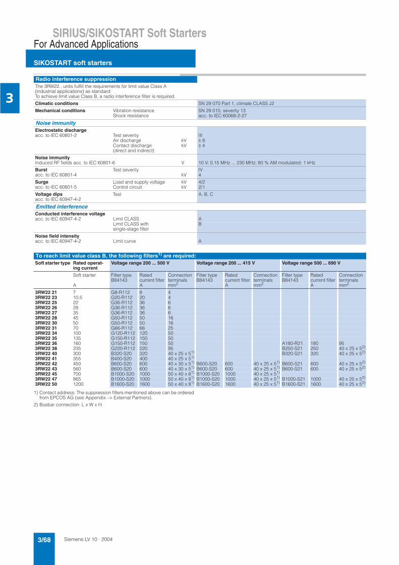
Siemens LV 10 · 20043/68
SIRIUS/SIKOSTART Soft Starters
SIKOSTART soft starters
For Advanced Applications
3
1) Contact address: The suppression filters mentioned above can be ordered from EPCOS AG (see Appendix –> External Partners).
2) Busbar connection: L x W x H.
Radio interference suppressionThe 3RW22.. units fulfill the requirements for limit value Class A (industrial applications) as standard. To achieve limit value Class B, a radio interference filter is required.
Climatic conditions SN 29 070 Part 1, climate CLASS J2
Mechanical conditions Vibration resistance SN 29 010, severity 13Shock resistance acc. to IEC 60068-2-27
Noise immunityElectrostatic dischargeacc. to IEC 60801-2 Test severity III
Air discharge kV ± 8Contact discharge (direct and indirect)
kV ± 4
Noise immunityInduced RF fields acc. to IEC 60801-6 V 10 V; 0.15 MHz ... 230 MHz; 80 % AM modulated: 1 kHz
Burst acc. to IEC 60801-4
Test severity IVkV 4
Surge acc. to IEC 60801-5
Load and supply voltage kV 4/2Control circuit kV 2/1
Voltage dips acc. to IEC 60947-4-2
Test A, B, C
Emitted interferenceConducted interference voltage acc. to IEC 60947-4-2 Limit CLASS A
Limit CLASS with single-stage filter
B
Noise field intensityacc. to IEC 60947-4-2 Limit curve A
To reach limit value class B, the following filters1) are required:Soft starter type Rated operat-
ing current Voltage range 200 ... 500 V Voltage range 200 ... 415 V Voltage range 500 ... 690 V
Soft starter Filter type B84143
Ratedcurrent filter
Connectionterminals
Filter type B84143
Ratedcurrent filter
Connectionterminals
Filter type B84143
Ratedcurrent filter
Connection terminals
A A mm2 A mm2 A mm2
3RW22 21 7 G8-R112 8 43RW22 23 10.5 G20-R112 20 43RW22 25 22 G36-R112 36 63RW22 26 28 G36-R112 36 63RW22 27 35 G36-R112 36 63RW22 28 45 G50-R112 50 163RW22 30 50 G50-R112 50 163RW22 31 70 G66-R112 66 253RW22 34 100 G120-R112 120 503RW22 35 135 G150-R112 150 503RW22 36 160 G150-R112 150 50 A180-R21 180 953RW22 38 235 G220-R112 220 95 B250-S21 250 40 x 25 x 52)
3RW22 40 300 B320-S20 320 40 x 25 x 51) B320-S21 320 40 x 25 x 52)
3RW22 41 355 B400-S20 400 40 x 25 x 51)
3RW22 42 450 B600-S20 600 40 x 30 x 51) B600-S20 600 40 x 25 x 51) B600-S21 600 40 x 25 x 52)
3RW22 43 560 B600-S20 600 40 x 30 x 51) B600-S20 600 40 x 25 x 51) B600-S21 600 40 x 25 x 52)
3RW22 45 700 B1000-S20 1000 50 x 40 x 81) B1000-S20 1000 40 x 25 x 51)
3RW22 47 865 B1000-S20 1000 50 x 40 x 81) B1000-S20 1000 40 x 25 x 51) B1000-S21 1000 40 x 25 x 52)
3RW22 50 1200 B1600-S20 1600 50 x 40 x 81) B1600-S20 1600 40 x 25 x 51) B1600-S21 1600 40 x 25 x 52)

Siemens LV 10 · 2004 3/69
SIRIUS/SIKOSTART Soft StartersFor Advanced Applications
SIKOSTART soft starters
3
Un = mains voltage
Type 3RW22 ..-..B1.
Version With solid-state device protection and RS 232 serial PC interface
Adjustability of functions in the various device versions on the unit, with potentiometers via a PC, withCOM SIKOSTART
Start-up Breakaway pulse Amplitude % 20 ... 100 x Un 21 ... 100 x Un
Duration ms 50 ... 1000 100 ... 1000
Start ramp Starting voltage % 20 ... 100 x Un
Duration s 0.3 ... 180 0 ... 1000
Current limiting Amplitude 50 % ... 600 % x Ie(Ie: rated operating current)
Numerical value in ampere, from 1 A to max. 6553 A or max. 6 x Ie(Ie: rated operating current)
Duration until starting is detected
Voltage limiting Amplitude % - 20 ... 100 x Un
Duration s - 0 ... 1000
Start-up detection Function Automatic increase of the motor terminal voltage to 100 % x Un on reaching the rated speed through p.f. and current detection.
p.f. detection can be deactivated x
Emergency start (only start ramp active)
x
Operation Energy saving mode x
Bridging contactor operation x
Continuous operation at max. 115 % Ie (full control of the thyristors)
x
Starting Ramp-down x
Smooth ramp-down Starting voltage of the stop ramp % fixed90 x Un
20 ... 100 x Un
Switch-off voltage of the stop ramp
% 85 of the starting voltage of the start ramp
20 ... 100 x Un
Ramp-down time s 1 ... 20 0 ... 1000
Pump ramp-down Switch-off voltage of pump ramp-down
% - 20 ... 90 x Un
Ramp-down time s 5 ... 90 5 ... 200
DC braking Braking torque Inversely proportional to the braking time, 20 % ... 85 % of the max. possible braking torque
20 % ... 100 % of the max. possi-ble braking torque, regardless of braking time
Braking time s 3 ... 18 1 ... 18

Siemens LV 10 · 20043/70
SIRIUS/SIKOSTART Soft Starters
SIKOSTART soft starters
For Advanced Applications
3
Selection and ordering data
The 3RW22 solid-state soft starters are designed for normaloperation (inertia load of the overall operating mechanism Jload < 10 x Jmotor; starting current 300 % for 30 s or similar load, e.g. large fans). For any other conditions of use, the devices should be selected using the Win-SIKOSTART selection and simulation program. See Technical specifications for information about rated currents for ambient temperatures >40 °C.
Soft starter selection depends on the motor’s rated current.
3RW22 21 3RW22 23 and 3RW22 25 3RW22 26 ... 3RW22 31 3RW22 34 ... 3RW22 41
Rated operat-ing voltage Ue
At ambient temperature 40 °C At ambient temperature 55 °C DT Order No. PS* Weight per PU approx.
Ratedoperat-ing cur-rent Ie
Rated output of three-phase induction motors for rated operating voltage Ue
Ratedoperat-ing cur-rent Ie
Rated output of three-phase induction motors for rated operat-ing voltage Ue
230 V 400 V 500 V 690 V 1000 V 200 V 230 V 460 V 575 V
V A kW kW kW kW kW A hp hp hp hp kgSoft starters for three-phase asynchronous motors with electronic protectionand serial RS 232 interface200 ... 500 7 1.5 3 4 - - 5.5 1 1 3 - 3RW22 21-1AB15 1 unit 2.210
10.5 2.2 4 5.5 - - 9 2 2 5 - 3RW22 23-1AB15 1 unit 3.56022 5.5 11 15 - - 16 3 5 10 - 3RW22 25-1AB15 1 unit 3.710
28 7.5 15 18.5 - - 22 5 7.5 15 - 3RW22 26-1AB15 1 unit 4.910
35 7.5 18.5 22 - - 32 10 10 20 - 3RW22 27-1AB15 1 unit 5.46045 11 22 30 - - 37 10 10 25 - 3RW22 28-1AB15 1 unit 5.460
50 15 22 30 - - 45 10 15 30 - 3RW22 30-1AB15 1 unit 8.50070 18.5 37 45 - - 63 20 20 40 - 3RW22 31-1AB15 1 unit 8.920
100 30 55 75 - - 85 25 30 60 - 3RW22 34-0DB15 1 unit 16.000135 37 75 90 - - 110 30 40 75 - 3RW22 35-0DB15 1 unit 17.100160 45 90 110 - - 140 40 50 100 - 3RW22 36-0DB15 1 unit 16.500
235 75 132 160 - - 205 60 75 150 - 3RW22 38-0DB15 1 unit 20.600300 90 160 200 - - 250 75 100 200 - 3RW22 40-0DB15 1 unit 20.600355 110 200 250 - - 300 100 100 250 - 3RW22 41-0DB15 1 unit 20.700
450 132 250 315 - - 355 100 125 300 - A 3RW22 42-0DB15 1 unit 62.000560 160 315 400 - - 450 150 150 350 - A 3RW22 43-0DB15 1 unit 64.100700 200 400 500 - - 560 200 200 450 - A 3RW22 45-0DB15 1 unit 40.000
865 250 500 630 - - 700 250 250 600 - A 3RW22 47-0DB15 1 unit 103.000
1200 400 710 900 - - 1000 350 400 850 - A 3RW22 50-0DB15 1 unit 131.000
200 ... 415 450 132 250 - - - 355 100 125 - - A 3RW22 42-0DB14 1 unit 57.400560 160 315 - - - 450 150 150 - - A 3RW22 43-0DB14 1 unit 58.600700 200 400 - - - 560 200 200 - - A 3RW22 45-0DB14 1 unit 52.000
865 250 500 - - - 700 250 250 - - A 3RW22 47-0DB14 1 unit 96.400
1200 400 710 - - - 1000 350 400 - - A 3RW22 50-0DB14 1 unit 70.000
500 ... 690 160 - - 110 160 - 140 - - - 125 C 3RW22 36-0DB16 1 unit 17.500
235 - - 160 200 - 205 - - - 200 C 3RW22 38-0DB16 1 unit 20.600300 - - 200 315 - 250 - - - 250 C 3RW22 40-0DB16 1 unit 21.100
450 - - 315 450 - 355 - - - 350 A 3RW22 42-0DB16 1 unit 57.300560 - - 400 560 - 450 - - - 450 C 3RW22 43-0DB16 1 unit 16.200
865 - - 630 900 - 700 - - - 700 C 3RW22 47-0DB16 1 unit 130.000
1200 - - 900 1200 - 1000 - - - 1000 X 3RW22 50-0DB16 1 unit 130.000
1000 160 - - - - 200 140 - - - - C 3RW22 36-0DB18 1 unit 20.900
300 - - - - 400 250 - - - - C 3RW22 40-0DB18 1 unit 63.600
450 - - - - 630 355 - - - - C 3RW22 42-0DB18 1 unit 45.000
* This quantity or a multiple thereof can be ordered.

Siemens LV 10 · 2004 3/71
SIRIUS/SIKOSTART Soft StartersFor Advanced Applications
SIKOSTART soft starters
3
Accessories
1) The program can also be downloaded free of charge from the Internet at www.siemens.de/sanftstarter.
Simply enter the search term "COM SIKOSTART" at this address.
Spare parts
DT Order No. PS* Weight per PU approx.
kgPlanning, Commissioning & Installation manualGerman X E20001-P285-A484-V3 1 unit on req.English B E20001-P285-A484-V2-7600 1 unit on req.Spanish B E20001-P285-A484-V2-7800 1 unit on req.
COM SIKOSTART PC communication program 1)
User interface for PC communication via RS 232 serial interface in English, French, German, Italian and Spanish.Disk format 3 1/2"
3RW27 01-0AA00 1 unit 0.078
Cablefor PC communication (modified RS 232 cable) 5 m long 3RW29 20-1DA00 1 unit 0.176Enclosurefor IP54 degree of protectionfor 3RW22 23 ... 3RW22 31
3RW29 20-0AB00 1 unit 8.590
Operating instructionsOperating manuals in English, French, German, Italian, Portuguese and Spanish (supplied with the unit as standard) can be downloaded free of charge as an Acrobat Reader file from the Internet at www.siemens.com/automation/manuals. Enter "SIKOSTART manuals" as a search term or "3RW22 manuals" as the search term.
B 3ZX1012-0RW22-1AN1 1 unit 0.263
For solid-state soft starters Maximum number required per device
DT Order No. PS* Weight per PU approx.
kgControl unit with solid-state device protection and RS 232 serial interface3RW22 ..-0DB14, 3RW22 ..-0DB15 1 3RW29 20-1BC05 1 unit 1.1903RW22 ..-0DB16 1 A 3RW29 20-1BC06 1 unit 1.2103RW22 ..-0DB18 1 A 3RW29 20-1BC08 1 unit 1.220Thyristor assembly3RW22 42-0DB14, 3RW22 43-0DB14 3 A 3RW29 20-6KC00 1 unit 8.5003RW22 45-0DB14 3 A 3RW29 20-6KD00 1 unit 7.1403RW22 47-0DB14 3 D 3RW29 20-6KE00 1 unit 9.8703RW22 50-0DB14 3 D 3RW29 20-6KH00 1 unit 26.700
3RW22 42-0DB15, 3RW22 43-0DB15 3 A 3RW29 20-6LC00 1 unit 4.7803RW22 45-0DB15 3 A 3RW29 20-6LD00 1 unit 5.6303RW22 47-0DB15 3 A 3RW29 20-6LE00 1 unit 17.5003RW22 50-0DB15 3 A 3RW29 20-6LH00 1 unit 25.500
3RW22 42-0DB16, 3RW22 43-0DB16 3 A 3RW29 20-6MC00 1 unit 9.3303RW22 47-0DB16 3 D 3RW29 20-6ME00 1 unit 30.000Current transformers3RW22 34-0DB1., 3RW22 35-0DB1., 3RW22 36-0DB1., 3RW22 37-0DB1. 1 A 3RW29 20-2AD00 1 unit 0.3363RW22 38-0DB1., 3RW22 40-0DB1. 1 A 3RW29 20-2AE00 1 unit 0.2733RW22 41-0DB1. 1 A 3RW29 20-2AK00 1 unit 0.2823RW22 42-0DB1., 3RW22 43-0DB1. 1 A 3RW29 20-2AH00 1 unit 0.5153RW22 45-0DB1. A 3RW29 20-2AL00 1 unit 0.4403RW22 47-0DB1., 3RW22 50-0DB1. 1 A 3RW29 20-2AJ00 1 unit 0.945Fans3RW22 34-0DB1., 3RW22 35-0DB1., 3RW22 36-0DB1.1), 3RW22 37-0DB1., 1 A 3RW29 20-3AC00 1 unit 0.6193RW22 38-0DB1.3RW22 36-0DB18, 3RW22 40-0DB1.1), 3RW22 41-0DB1 2 A 3RW29 20-3AC00 1 unit 0.6193RW22 42-0DB1.1), 3RW22 40-0DB18 3 A 3RW29 20-3AF00 1 unit 0.7183RW22 43-0DB1., 3RW22 42-0DB18, 3RW22 45-0DB1. 3 A 3RW29 20-3AD00 1 unit 1.2503RW22 47-0DB1., 3RW22 50-0DB1. 3 A 3RW29 20-3AE00 1 unit 0.985Surge suppressor circuit3RW22 34-0DB1., 3RW22 35-0DB1., 3RW22 36-0DB1. 1 A 3RW29 20-4AC00 1 unit 0.2193RW22 37-0DB1., 3RW22 38-0DB1., 3RW22 40-0DB1., 3RW22 41-0DB1.3RW22 42-0DB1., 3RW22 43-0DB1., 3RW22 47-0DB1., 3RW22 50-0DB1.
12
AA
3RW29 20-4AD003RW29 20-4AD00
1 unit1 unit
0.2850.285
Temperature sensors3RW22 21-1AB1. to 3RW22 31-1AB1. 1 A 3RW29 00-3AA00 1 unit 0.0073RW22 34-0DB1. to 3RW22 50-0DB1. 1 A 3RW29 00-3BA00 1 unit 0.008Covers3RW22 34-0DB1. to 3RW22 41-0DB1.1) 1 A 3RW29 20-0BA00 1 unit 0.3923RW22 42-0DB1. to 3RW22 45-0DB1., 3RW22 40-0DB18 1 A 3RW29 20-0BB00 1 unit 2.1203RW22 47-0DB14, 3RW22 47-0DB15 1 A 3RW29 20-0BC00 1 unit 1.7003RW22 47-0DB16, 3RW22 50-0DB1. 1 D 3RW29 20-0BD00 1 unit 3.300
1) Does not apply to 3RW22 ..-0DB18
* This quantity or a multiple thereof can be ordered.
Siemens LV 10 · 20043/72
SIRIUS/SIKOSTART Soft Starters
SIKOSTART soft starters
For Advanced Applications
3
Further information
Configuration
The 3RW22 solid-state starters are designed for normal starting. In case of heavy starting or increased starting frequency, a larger unit must be selected.
If necessary, an overload relay for heavy-starting must be se-lected where long starting times are involved. PTC thermistor de-tectors are recommended. This also applies for the ramp-down modes soft ramp-down, pump ramp-down and DC braking, be-cause during the ramp-down time in these modes, an additional current loading applies in contrast to free ramp-down.
In the motor feeder between the SIKOSTART and the motor, no capacitive elements are permitted (e.g. compensation equip-ment).
All elements of the main circuit (such as fuses, switching devices and overload relays) should be dimensioned for direct starting, following the local short-circuit conditions. Fuses, switching de-vices and overload relays must be ordered separately.
The harmonic component load for starting currents must be taken into consideration for the selection of circuit-breakers (selection of release).
Use with EEx-protected motors
The units are suitable for starting EEx-protected motors with types of protection "d", "p" and "n", insofar as the relevant mode does not give rise to any expected noteworthy influence of start-ing behavior on heat development.
Explanation:Type of protection• "d" = flameproof enclosure• "p" = overpressure enclosure• "n" = designed for Zone 2
SIEMENS has received a confirmation from the German national standards laboratory (PTB) in Brunswick that, in relation to mo-tors with the type of protection "d", there are no objections to in-cluding starting with SIKOSTART within the scope of the condi-tions upon which the general conformity certificates are based, and that there is no need to expressly mention this.
Express mention of this in the conformity certificate of the motors will also not be necessary in the future.
The devices are suitable for starting EEx-protected motors with types of protection "e" provided heavy starting is not involved. The ramp time on the unit must be set to a value that is at most equal to the TE time of the machine. A test report with the PTB No. 3.53-542/96 is available.
Manual for SIKOSTART 3RW22
Besides containing all important information on planning, com-missioning and servicing, the manual also contains suggested circuits and the technical data for all devices.
Electronic overload protection, serial RS 232 PC interface and COM SIKOSTART PC communication program
In addition to the electronic device protection, the 3RW22 elec-tronic motor controllers feature a PC communication interface.
Together with the PC program COM SIKOSTART, it enables sim-ple parameter definition, control and observation of SIKOSTART 3RW22 via a PC or a notebook.
Once entered, a parameter set can be stored in the PC and then retrieved when defining the parameters of a unit with the same kind of drive.
Parameters can be entered more precisely and independently of one another than when using the potentiometers.
It is also possible to store two or three parameter sets in the SIKOSTART 3RW22. Thus, the units are excellently suitable for use with Dahlander and reversible-pole motors, wind energy systems and for serial starting of motors with different outputs or loads.
Win-SIKOSTART selection and simulation program
With this software, you can simulate and select all Siemens soft starters, taking into account various parameters such as mains properties, motor and load data, and special application re-quirements.
The software is a valuable tool, which makes complicated, lengthy manual calculations for determining the required soft starters superfluous.
You can order the CD-ROM under the following order number: Order No.: E20001-D1020-P302-X-7400.
SIKOSTART training course (D91/D92)
Siemens offers a 2-day training course on the SIKOSTART solid-state motor controllers to keep customers and own personnel up-to-date on configuring, commissioning and servicing issues.
Please direct enquiries and applications to:
Training Center I&S IS E&C TC Werner-von-Siemens-Str. 65 D-91052 Erlangen Telephone:++49 (9131) 72 92 62 Telefax: ++49 (9131) 72 81 [email protected]/sibrain

Siemens LV 10 · 2004 3/73
SIRIUS/SIKOSTART Soft StartersFor Standard and Advanced Applications
Project planning aids
3
Dimension drawings
for standard applications
1) Drilling template
3RW30 03-1.... (screw-type terminals) 3RW30 03-2.... (spring-type terminals)
5
NSC00482
101,
6
ca. 7
1
7,2
ca. 9
1
81,6
120
1)
3,1
22,5
3RW30 1. 3RW30 2. and 3RW31 2.
3RW30 3. 3RW30 4.
1)
NS
B00
434
35
115
7
5
125
101
63
14
45
6396
5
785
119
81
1)160
18
77119
55
5 63115
8108
143
30
150
5
NS
B00
435
NSB00436
60
160
7
5
170
132
87
22,5
70
87156
5
8
108
162 1)
178
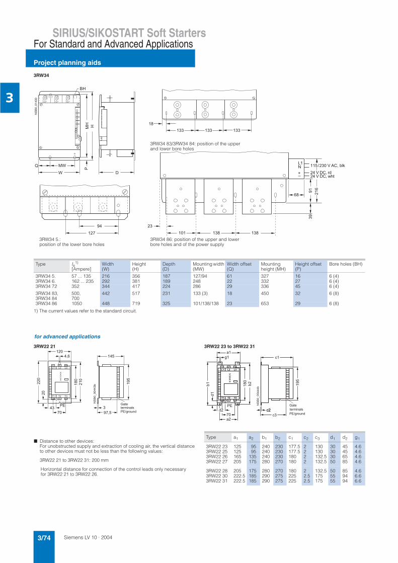
Siemens LV 10 · 20043/74
SIRIUS/SIKOSTART Soft Starters
Project planning aids
For Standard and Advanced Applications
3
1) The current values refer to the standard circuit.
3RW34
Type Ie1)
[Ampere]Width(W)
Height(H)
Depth(D)
Mounting width (MW)
Width offset (Q)
Mountingheight (MH)
Height offset (P)
Bore holes (BH)
3RW34 5. 57 ... 135 216 356 187 127/94 61 327 16 6 (4)3RW34 6. 162 ... 235 292 381 189 248 22 332 27 6 (4)3RW34 72 352 344 417 224 286 29 336 45 6 (4)
3RW34 83, 3RW34 84
500,700
442 517 231 133 (3) 18 450 32 6 (8)
3RW34 86 1050 448 719 325 101/138/138 23 653 29 6 (8)
;
!!!!!!
,
2
"
*
'&"!#8<=
"#>?"#@A$
),
2 ")
!2
"!
!, !,
3RW34 83/3RW34 84: position of the upper and lower bore holes
3RW34 86: position of the upper and lower bore holes and of the power supply
3RW34 5.: position of the lower bore holes
for advanced applications
3RW22 21 3RW22 23 to 3RW22 31
! " #
$
$
#
$
$
#
! " #
7 Distance to other devices:For unobstructed supply and extraction of cooling air, the vertical distance to other devices must not be less than the following values:
3RW22 21 to 3RW22 31: 200 mm
Horizontal distance for connection of the control leads only necessaryfor 3RW22 21 to 3RW22 26.
Type a1 a2 b1 b2 c1 c2 c3 d1 d2 g1
3RW22 23 125 95 240 230 177.5 2 130 30 45 4.63RW22 25 125 95 240 230 177.5 2 130 30 45 4.63RW22 26 165 135 240 230 180 2 132.5 30 65 4.63RW22 27 205 175 280 270 180 2 132.5 50 85 4.6
3RW22 28 205 175 280 270 180 2 132.5 50 85 4.63RW22 30 222.5 185 290 275 225 2.5 175 55 94 6.63RW22 31 222.5 185 290 275 225 2.5 175 55 94 6.6

Siemens LV 10 · 2004 3/75
SIRIUS/SIKOSTART Soft StartersFor Standard and Advanced Applications
Project planning aids
3
3RW22 34 to 3RW22 41 3RW22 42 to 3RW22 50
Controlconnectionterminals
!
"#
$%
&
'
(
)
Control connectionterminals
7 Distance to other devices:For unobstructed supply and extraction of cooling air, the vertical distance to other devices must not be less than the following values:
3RW22 34 to 3RW22 45: 200 mm3RW22 47 and 3RW22 50: 400 mm
1) 3RW22 40-0DB18 has identical dimensionsto 3RW22 42-0DB15!
Type a b
3RW22 34 to 3RW22 36 20 33RW22 38 to 3RW22 411) 25 5
Type H B T a b c d e f g
3RW22 42, 655 465 255 400 90 11 605 80 210 3703RW22 43,3RW22 45
3RW22 47 730 560 340 480 115 11 680 100 260 460
3RW22 50, 875 600 330 520 115 13 825 105 275 4853RW22 47-0DB16
Type m n p r t v w x y z
3RW22 42, 15 570 145 215 20 25 87.5 30 5 113RW22 43,3RW22 45
3RW22 47 20 645 230 295 25 27 100 40 8 13
3RW22 50, 20 790 220 285 25 29 110 50 10 133RW22 47-0DB16
3RW29 20-0AB00
% % % %
%
#!!%!&
' ( % ! ) %
" * % "
$+%
Top view View from below

Siemens LV 10 · 20043/76
Motor Management Systems
SIMOCODE-DP motor protection and control devices
3
Overview
SIMOCODE-DP Basic Unit, Expansion Module and Operator Module
The communication-capable SIMOCODE-DP 3UF5 MotorProtection and Control Unit is used, in particular, in low-voltage controlgear for motor control centers in the process engineering-industry and forms the intelligent connection between the motor feeder (motors with constant speed) and the process control system.
With this technology, plant availability can be increased and at the same time, cost savings are achieved for construction, com-missioning and during operation of a plant.
SIMOCODE-DP offers the solution for a wide range of different tasks in a single unit:• Multifunctional, electronic motor protection and plant monitor-
ing• Comprehensive motor and plant diagnostics• Integrated control programs (instead of extensive hardware
wiring)• Open communication via PROFIBUS DP, the standard for field-
bus systems.
Easy construction of a motor feeder with SIMOCODE-DP
Multifunctional, electronic motor protection and plant monitoring
SIMOCODE-DP features a combination of numerous protective mechanisms such as• Current-sensitive motor protection (CLASS 5-30)• Thermistor motor protection• Rotor locking protection• Ground-fault monitoring, as well as• Monitoring adjustable current limits
to ensure problem-free processes.
The current transformer for measuring the motor current is al-ready built into SIMOCODE-DP.
Rated motor currents from 0.25 to 820 A are supported by just six variants.
Comprehensive motor and plant diagnostics
SIMOCODE-DP provides a variety of operating, service and diagnostic data, such as • The currently flowing phase current • Switching state of the motor• Motor operating hours• Number of switching cycles of the motor• Number of overload tripping operations, as well as• Detailed early warning messages or error messages.
The following advantages result:• Faults can be prevented• The plant electrician or process operator is comprehensively
informed about the operational status of the load feeder• Errors can be diagnosed and rectified quickly.
L1L2L3NPE
-Q1
-K2 -K3-K1
1U 1V 1W
2W 2U 2V
1M3 ~1
PROFIBUS-DP
ReadyGen. Fault
Test/Reset
-K2 -K3-K1
NSA0_00350
Automation levelApplication
CommunicationProtection Control
Basic unit
ControlmoduleON
OFF
MonitoringInterlockingPartial application
OverloadThermistorEarth fault
Control commandsOperational dataDiagnostics dataAssignment

Siemens LV 10 · 2004 3/77
Motor Management Systems
SIMOCODE-DP motor protection andcontrol devices
3
Integrated control programs (instead of extensive hardware wiring)
In SIMOCODE-DP, many predefined motor control functions can be called up, such as• Direct on-line starter• Reversing starter• Star-delta starter• Two speeds, motors with a separate winding• Two speeds, motors with a separate Dahlander winding• Gate valve control• Solenoid valve or• Soft starter.
All the interlocks and logic operations necessary for operation of the required motor controls are included in their software and switch the motor contactors on or off directly by means of the SIMOCODE-DP relay outputs.
These ready-to-use control functions can also be adapted to each customized variant of a motor feeder by means of freely-parameterizable elements, such as timers, counters, logic oper-ations (AND, OR, NOR, etc.).
Wiring overhead for the control circuit is reduced considerably and a high level of standardization is achieved for the motor feeder in terms of hardware structure and circuit diagrams.
Open communication via PROFIBUS DP, the standard for fieldbus systems
SIMOCODE-DP with its integrated PROFIBUS DP interface re-places the complete system of single wires including marshal-ling racks, which would otherwise be necessary for data transfer to and from the higher-level automation system.
The otherwise complex and expensive cabling is thus reduced to a single 2-wire cable.
SIMOCODE-DP supports the communication functions of• DP-V0 (cyclic data transfer, GSD configuration, diagnostics)
and• DP-V1 (non-cyclic data transfer, integration into engineering
tools with EDD, interrupts).
With SIMOCODE-DP, the following baud rates (Kbits/s) are pos-sible:• 9.6• 45.45• 93.75• 187.5• 500• 1500
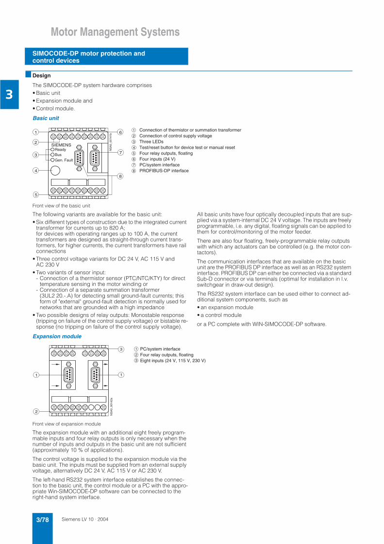
Siemens LV 10 · 20043/78
Motor Management Systems
SIMOCODE-DP motor protection and control devices
3
Design
The SIMOCODE-DP system hardware comprises • Basic unit • Expansion module and • Control module.
Basic unit
Front view of the basic unit
The following variants are available for the basic unit:• Six different types of construction due to the integrated current
transformer for currents up to 820 A;for devices with operating ranges up to 100 A, the current transformers are designed as straight-through current trans-formers, for higher currents, the current transformers have rail connections
• Three control voltage variants for DC 24 V, AC 115 V and AC 230 V
• Two variants of sensor input: - Connection of a thermistor sensor (PTC/NTC/KTY) for direct
temperature sensing in the motor winding or- Connection of a separate summation transformer
(3UL2 20.-.A) for detecting small ground-fault currents; this form of "external" ground-fault detection is normally used for networks that are grounded with a high impedance
• Two possible designs of relay outputs: Monostable response (tripping on failure of the control supply voltage) or bistable re-sponse (no tripping on failure of the control supply voltage).
All basic units have four optically decoupled inputs that are sup-plied via a system-internal DC 24 V voltage. The inputs are freely programmable, i.e. any digital, floating signals can be applied to them for control/monitoring of the motor feeder.
There are also four floating, freely-programmable relay outputs with which any actuators can be controlled (e.g. the motor con-tactors).
The communication interfaces that are available on the basic unit are the PROFIBUS DP interface as well as an RS232 system interface. PROFIBUS DP can either be connected via a standard Sub-D connector or via terminals (optimal for installation in l.v. switchgear in draw-out design).
The RS232 system interface can be used either to connect ad-ditional system components, such as • an expansion module• a control module
or a PC complete with WIN-SIMOCODE-DP software.
Expansion module
Front view of expansion module
The expansion module with an additional eight freely program-mable inputs and four relay outputs is only necessary when the number of inputs and outputs in the basic unit are not sufficient (approximately 10 % of applications).
The control voltage is supplied to the expansion module via the basic unit. The inputs must be supplied from an external supply voltage, alternatively DC 24 V, AC 115 V or AC 230 V.
The left-hand RS232 system interface establishes the connec-tion to the basic unit, the control module or a PC with the appro-priate Win-SIMOCODE-DP software can be connected to the right-hand system interface.
5
SIEMENS
1 6
2
3
48
7
NS
A0_
0014
1b
ReadyBusGen. Fault
1
2
3
4
5
6
7
8
Connection of thermistor or summation transformer Connection of control supply voltage Three LEDs Test/reset button for device test or manual resetFour relay outputs, floatingFour inputs (24 V)PC/system interface PROFIBUS-DP interface
2
3
1 1
NS
A0_
0014
2a
PC/system interfaceFour relay outputs, floatingEight inputs (24 V, 115 V, 230 V)
1
2
3

Siemens LV 10 · 2004 3/79
Motor Management Systems
SIMOCODE-DP motor protection andcontrol devices
3
Control module
Front view of control module
The control module is used to control the motor feeder from the door of the control cabinet and therefore replaces all the conven-tional pushbuttons and indicator lights that would otherwise be necessary for monitoring and controlling the motor.
Via the RS232 system interface on the rear, the control module can be connected to the basic unit or the expansion module. Power is supplied from the basic unit.
The three pushbuttons are freely programmable, but it is appro-priate to use them for controlling the motor feeder.
A total of eight LEDs are available, six of which are freely pro-grammable. Depending on the application, various different sig-nals can be indicated.
A PC with the Win-SIMOCODE-DP software can be connected via the front RS232 system interface (with cover for IP54).
Safe isolation
All electric circuits in SIMOCODE-DP (from product version 12, start of delivery 01/2000) are safely isolated from each other ac-cording to • DIN VDE 0100 (similar to IEC 60364),• DIN VDE 0106 (or new standard EN 50274),• EN 50178.
That is, they are designed with double leakage paths and clear-ances. In the event of a fault, therefore, no parasitic voltages can be formed in neighboring circuits. In this context, compliance with the instructions in the test report Safe isolation No. 1610a is required.
Connection and mounting
Devices with current adjustment ranges from 1.25 to 100 A (overall width 70 mm) are designed for installation as a single unit due to the straight-through current transformer, i.e. they are either snapped onto a 35 mm standard rail to EN 50022 or screwed onto a mounting plate using push-in lugs that are avail-able as accessories.
The main conductors are simply passed through the straight-through current transformer integrated into the enclosure, using multiple loops, loads with rated motor currents of less than 1.25 A can also be protected.
With current adjustment ranges greater than 100 A to 820 A (overall widths: 120 mm, 145 mm and 230 mm), the devices can be directly fitted to the contactor via the connecting rails of the current transformer.
A screw fastening for these devices is integrated in the enclo-sure.
For the basic units (overall width:120 mm), a baseplate for snap-on attachment on a 75 mm standard mounting rail is available.
Functions
Protective and monitoring functions
For the protection of loads against impermissible high tempera-ture rises
Types of overload protection:• Current-sensitive, electronic overload protection with adjust-
able tripping characteristics (class times)SIMOCODE-DP protects three-phase or AC motors from over-loading in accordance with the requirements of IEC 60947-4-1. The class (trip class) indicates the maximum tripping time dur-ing which SIMOCODE-DP must trip at 7.2 times the operational current from cold. The trip class can be set in six stages from CLASS 5 to CLASS 30. The switch-off time can therefore be ex-tremely finely adjusted to the load torque of the motor – to op-timize utilization of the motor (see also the section Characteris-tics).
• Phase failure / unbalance monitoringA signal is output for a phase unbalance greater than 40 %. The tripping times of the overload characteristic are reduced, because the heat generated in the motor rises under unbal-anced conditions (additional eddy-current losses).
• Thermistor motor protectionTemperature-dependent motor protection is based on direct temperature measurements in the motor. These protective functions should be used, in particular, in motors with high op-erating frequencies, heavy-duty starting, intermittent and/or
braking operation, but also in the case of a blocked air supply or speeds lower than the rated speed. For this reason, a wide range of different temperature sensors are available that are in-stalled in the stator winding or in the motor enclosure. SIMOCODE-DP can evaluate the following sensor types: - Binary PTC sensors whose resistance rises sharply when the
temperature limit is reached- Analog temperature sensors, such as NTC, KTY83/84, which
have an almost linear characteristic and can therefore be set to any warning or switch-off temperatures.
EEx e type of protection
The SIMOCODE-DP system is in accordance with the regula-tions for overload protection of explosion-protected motors of the EEx e "Increased safety" type of protection to• EN 50019, IEC 60079-7 (increased safety e),• EN 60079-14, IEC 60079-14 (explosive gas atmospheres),• EN 50281 (presence of combustible dust),• and the ATEX/PTB test regulations.
In the case of SIMOCODE-DP units with DC 24 V control infeed, isolation by battery or safety transformer in accordance with EN 61558-2-6 must be assured.
EU prototype test certificate No.: PTB01 ATEX 3219
Test report: PTB EX 01-30013
SIEMENS
NSA0_00143a
Ready
Gen. Fault1
3
4
5
2 1 2
1
345
2Eight LEDsLabelling strips Test/reset button for device test or manual resetThree control keys PC/system interface, with cover

Siemens LV 10 · 20043/80
Motor Management Systems
SIMOCODE-DP motor protection and control devices
3
Rotor locking protection
When the motor current rises above a rotor locking threshold that can be set, SIMOCODE-DP does not trip in accordance with the overload characteristic, but switches off immediately instead. The prevention of unnecessary thermal loads prevents prema-ture aging of the motor. The rotor locking protection is not active for start-up monitoring until the class time has elapsed, e.g. for CLASS 10 after 10 seconds.
Ground-fault monitoring
Two qualitatively different ground-fault monitoring functions areoffered:• "Internal" ground-fault monitoring by means of calculation
The internal ground-fault monitoring is only suitable for motors with 3-wire connection and for networks that are grounded di-rectly or with a low impedance. In this case, the ground-fault current is calculated by vector addition of the phase currents of the SIMOCODE-DP current transformer. An additional sum-mation current transformer is not necessary. In fault-free sys-tems, the vectorial summation current of the three phases is zero; if this is not the case, an ground-fault is signaled. Ground-fault currents that are more than 30 % of the operating currentIe are detected.
• External ground-fault monitoring by means of measurementThe external ground-fault detection is normally used in supply systems that have a high impedance ground. An additional summation current transformer (3UL2 20.-.A) is required for this method that is also suitable for extremely low ground-faultcurrents. Detected fault current, depending on the summation current transformer: 0.3/0.5/1 A.
Current limit monitoring I>, I<
Current limit monitoring is not used for motor protection, but for process monitoring.
It is used to detect developing irregularities in the plant early, e.g. motor bearings becoming tight (consequence: upper limit responds) or the belt coupling to the drive machine tears (con-sequence: lower limit responds).
Comprehensive motor and plant diagnostics
SIMOCODE-DP provides a variety of measuring, operating and diagnostics data concerning the load feeder: • Up-to-date information during operation, e.g.
- The currently flowing phase current in %- The switching state of the motor (On, Off, clockwise, counter-
clockwise, fast, slow) derived from the current flow - Manual/automatic mode- Test mode- Cooling time activated after an overload tripping operation
• Detection of incipient faults, e.g. - Overload warning- Current limit overshoot- Phase unbalance- Thermistor warning
• Rapid diagnosis in the event of an alarm (up to 30 individual messages), e.g. - Overload- Thermistor motor protection- Rotor locking- Current limit overshoot- Checkback error (e.g. no current following On command)
• Preventive maintenance by means of statistical data, e.g.: - Number of starts- Number of overload trips- Tripping currents- Operating hours.
Integrated standard programs for motor control
In SIMOCODE-DP, a number of different opportunities for con-trolling the motor have been predefined and can be called up in the form of control functions:• Overload relay• Direct on-line starter• Reversing starter• Star-delta starter• Two speeds, Dahlander winding• Two speeds, separate winding• Valve• Actuator • Soft starter (SIKOSTART).
These control programs already include all the software inter-locks and logic operations required for operation of the required motor functions.
It is also monitored whether the checkback for current from the motor feeder is compatible with the control command. If not, SIMOCODE-DP opens the motor contactor and generates an alarm indication.
The motor can be controlled by any equipment in accordance with the application:• From the process control system of the PC via PROFIBUS DP• From the control cabinet door via the operator module• From a local control point on the motor, whereby the pushbut-
tons/switches are wired to the SIMOCODE-DP inputs.
The standard control functions can also be adapted to each cus-tomized variant of a motor feeder by means of freely-parameter-izable elements, such as timers, counters, logic operations (AND, OR, NOR, etc.).
Furthermore, special standard function blocks are stored in SIMOCODE-DP:• Automatic, time-discrete reactivation of motors following mains
failureThe prerequisites are as follows: - Failure of the three-phase supply must take place via a sep-
arate voltage relay- The supply voltage of SIMOCODE-DP must not be inter-
rupted• Different error signaling modules with and without acknowl-
edgementThese allow SIMOCODE-DP to trip as a result of external events (e.g. overspeed governor has tripped)
• The emergency start functionThis resets the thermal memory of SIMOCODE-DP immediately after overload tripping, i.e. immediate restarting is possible (important, for example, for a fire-extinguisher pump)
• The test function for the load feederThis can be activated by switching off the main switch Q1 (see the section Circuit Diagrams) and allows the control circuit to be checked with the motor branch at zero current.
Autonomous operation
A significant feature of SIMOCODE-DP is autonomous process-ing of all integral protection and control mechanisms, i.e. even in the event of failure of the bus system or automation system, cor-rect functioning of the motor feeder is guaranteed.

Siemens LV 10 · 2004 3/81
Motor Management Systems
SIMOCODE-DP motor protection andcontrol devices
3
Integration
Universal application of SIMOCODE-DP in any automation system
In communication-capable controlgear, over and above the de-vice function and hardware design a great deal of emphasis is placed on system integration, i.e. optimal integration capability in various different system configurations and process automa-tion systems.
For this reason, the SIMOCODE-DP modular system offers as options a wide range of software packages for system-wide and time-saving configuring and diagnostics:• PC software Win-SIMOCODE-DP for start-up and service• Object manager OM-SIMOCODE for "totally integrated" in
SIMATIC S7• Function block FB-SIMOCODE for "totally integrated" in PCS7.
PC software Win-SIMOCODE-DP for start-up and service
Win-SIMOCODE-DP is "Plug and Play"-capable, process inde-pendent standard PC software for start-up and service.
It offers a user-friendly and convenient user-interface for• Parameterization• Display and diagnostics• Test functions• Motor control
Win-SIMOCODE-DP is available in two versions:• Win-SIMOCODE-DP / Smart
Interfacing to SIMOCODE-DP via the RS232 interface, i.e. point-to-point
• Win-SIMOCODE-DP / ProfessionalInterfacing to SIMOCODE-DP selectable - Distributed via RS232- Centrally via PROFIBUS DP (V1).
'
!" #"# $
%&'
( )%*+, $-.
( )%',/
0*$##"# $
. .
)(
#*' .12 0 10..) ))2% &?)&

Siemens LV 10 · 20043/82
Motor Management Systems
SIMOCODE-DP motor protection and control devices
3
Object manager OM-SIMOCODE for "totally integrated" in SIMATIC S7
SIMOCODE-DP can be integrated into SIMATIC S7 in two differ-ent ways:• Conventionally via GSD files
i.e. integration in SIMATIC S7 is identical to integration in any other DP standard master system
• Via the OM-SIMOCODE-DP object manageri.e. SIMOCODE-DP becomes an integral component ofSTEP 7, the object manager OM-SIMOCODE-DP should, in this case, always be combined with the start-up and service soft-ware Win-SIMOCODE-DP/Professional.
Both software packages must be installed on the PG/PC on which the hardware configuration of SIMATIC S7 is performed.
This ensures that Win-SIMOCODE-DP/Professional can be called up directly from HW-Config.
Parameter sets created with Win-SIMOCODE-DP/Professional are loaded into the STEP 7 data storage by means of OM and au-tomatically transferred to SIMOCODE-DP during start-up.
Functions specific to SIMATIC S7, such as diagnostic and hard-ware interrupts are supported, which means easier S7-wide con-figuration as well as optimal performance in the transfer of diag-nostic data.
Function block FB-SIMOCODE for "totally integrated" in PCS7
System-compatible integration into the PCS7 process control system requires the appropriate function blocks and faceplates for the respective field device.
The PCS7-FB SIMOCODE-DP supports standard processing of the SIMOCODE-DP-specific data in the application program of the automation system.
The faceplate (picture block) SIMOCODE-DP offers a standard-ized user interface for SIMOCODE-DP on the Operator Station of PCS7.
It is then easy to integrate SIMOCODE-DP into PCS7 and time-savings are achieved during configuration.
The Process Device Manager "PDM" supports centralized pa-rameterization and diagnosis of all field devices onPROFIBUS DP or using the Hart protocol from thePC S7 Engineering Station.
SIMOCODE-DP is integrated into PDM via an appropriate device description. The functional scope corresponds to that ofWin-SIMOCODE-DP, the user-interface is, however, uniform for all the different types of field devices.
Technical specifications
Shared data of basic unit, expansion module and operator modulePermissible ambient temperature in °C -25 ... +60
Permissible storage temperature in °C -40 ... +80
Installation altitude above sea-level in m ≤ 2000
Degree of protection acc. to IEC 60529 IP20 max. current setting Ie ≤ 100 A; IP00 max. current setting Ie > 100 A
Shock resistance (sine pulse) 10 g/5 ms
Mounting position Any
Mounting• max. current setting Ie ≤ 100 A Snap-on mounting onto 35 mm standard rail or screw mounting with
push-in lugs.• max. current setting Ie > 100 A Screw mounting directly onto contactor or screw mounting
EMC interference immunity• Line-induced interference, burst to IEC 61000-4-4 2 kV (corresponds to degree of severity 3)• Line-induced interference, surge to IEC 61000-4-5 2 kV (corresponds to degree of severity 3)• Electrostatic discharge to IEC 61000-4-2 8 kV (corresponds to degree of severity 3)• Field-related interference to IEC 61000-4-3 10 V/m (corresponds to degree of severity 3)
EMC emitted interference Emission limit class B to EN 55011
Safe isolation acc. to DIN VDE 0100 (IEC 60364), DIN VDE 0106, EN 50178 (product version 12 upwards, start of delivery 01/2000)
All circuits in SIMOCODE-DP are safely isolated from each other, they are designed with doubled creepage paths and clearances
Power circuit from the control/electronic circuits: Safe isolation up to 690 V or 1000 V between control and electronic circuits
One below the other: Safe isolation up to 300 V
Observe notes of test report “Safe Isolation” No. 1610a.Basic unitDisplays• green LED "Ready" Continuous light: Ready
Off: No control supply voltage" or "Function test not OK; device is disabled"• green LED "Bus" Continuous light: “Bus operation"• red LED "General Fault" Continuous light/steady light: “Feeder fault”, e.g. overload tripping
Test/Reset button By pressing the Test/Reset button, the device can be reset following a trip or its functions can be tested
System interface RS 232 for connecting the expansion module, control module or PC
PROFIBUS DP interface RS 485 for connecting the PROFIBUS DP line via terminals (conductor cross-sections as for auxiliary contacts) or 9-pole SUB D socket

Siemens LV 10 · 2004 3/83
Motor Management Systems
SIMOCODE-DP motor protection andcontrol devices
3
Main circuitRated insulation voltage Ui (for pollution severity 3) in V• For uninsulated conductors (3UF5 001 to 3UF5 021) 690• For insulated conductors (3UF5 001 to 3UF5 021) 1000• For uninsulated and insulated conductors (3UF5 031 to 3UF5 051) 1000
Rated impulse withstand voltage Uimp in kV• 3UF5 001 ... 3UF5 021 6• 3UF5 031 ... 3UF5 051 8
Rated frequency in Hz 50/60
Type of current Three-phase
Short-circuit protection See table Short-circuit protection with fuses for motor feeders ....
Diameter of feed-through openings (max. Ie = 100 A) in mm• Devices with max. operational current Ie = 25 A 10• Devices with max. operational current Ie = 100 A 15• Devices with max. operational current Ie > 100 A Construction with connecting bars
Bar connection• Current range in A 50 ... 205 125 ... 500 200 ... 820• Tightening torque in Nm M 8: 10 ... 14 M 10: 14 ... 24 M 10: 14 ... 24
M 12: 20 ... 35• Solid with cable lug in mm2 35 ... 95 50 ... 240 50 ... 240• Stranded with cable lug in mm2 50 ... 120 70 ... 240 70 ... 240
Auxiliary circuit/control circuitRated control supply voltage Us AC 50/60 Hz; 115 V and 230 V 24 V DC
Operating range AC 50/60 Hz; 0.85 to 1.1 x Us DC 24 V; 0.85 ... 1.2 × Us (DIN 19240)
Power consumption AC 50/60 Hz; 5 VA DC 24 V; 5 W
Rated insulation voltage Ui in V 300 (at pollution degree 3)
Rated impulse withstand voltage Uimp in kV 4
Outputs• Number 4 monostable/bistable outputs depending on the variant• Auxiliary contacts of the 4 outputs NC contact response can be parameterized with internal signal conditioning,
3 outputs are jointly and 1 is separately connected to a common potential; they can be freely assigned to the control functions (e.g. for activating mains, star and delta contactors and for signaling the operating status)
• Specified short-circuit protection for auxiliary contacts (outputs) Fuse links, operational class gL/gA 6 A, quick-acting 10 A;circuit-breaker 1.6 A, C characteristic
Continuous rated current in A 5
Rated operating current (switching capacity) AC-15; 6 A/24 V; 6 A/120 V; 3 A/230 VDC-13; 2 A/24 V; 0.55 A/60 V; 0.25 A/125 V
Inputs 4 inputs, supplied by the device electronics (DC 24 V), jointly connected to a common potential, for injecting process signals such as local control points, key-operated switches or limit switches
Thermistor motor protection (binary PTC thermistor)• Total cold resistance in kΩ 1.5• Response threshold in kΩ 2.7 ... 3.1• Return value in kΩ 1.5 ... 1.65
Conductor cross-sections• Tightening torque in Nm 0.8 ... 1.2• Solid and stranded in mm2 1 × (0.5 ... 4.0); 2 × (0.5 ... 2.5)• Solid with/without end sleeve in mm2 1 × (0.5 ... 2.5); 2 × (0.5 ... 1.5)
Expansion moduleSystem interface RS 232 as connection to the basic unit and for connecting the control
module or PC
Rated insulation voltage Ui in V 300 (at pollution degree 3)
Rated impulse withstand voltage Uimp in kV 4
Outputs• Number 4 bistable outputs• Auxiliary contacts of the 4 outputs Each with 1 floating NO contact, NC contact response can be parameterized
via internal signal conditioning; 3 outputs jointly and 1 separately connected to common potential; they can be freely assigned to the control functions (e.g. for activating mains, star and delta contactors and signaling the operat-ing status)
• Specified short-circuit protection for auxiliary contacts (outputs) Fuse links, operational class gL/gA 6 A, quick-acting 10 A; Circuit-breaker 1.6 A, C characteristic
Continuous rated current in A 5
Rated operating current (switching capacity) AC-15; 6 A/24 V; 6 A/120 V; 3 A/230 VDC-13; 2 A/24 V; 0.55 A/60 V; 0.25 A/125 V
Inputs 8 externally supplied DC 24 V, AC 115 V, AC 230 V jointly connected to a common potential, for injecting process signals such as local control points, key-operated switches or limit switches
Conductor cross-sections• Tightening torque in Nm 0.8 ... 1.2• Solid and stranded in mm2
1 × (0.5 ... 4.0); 2 × (0.5 ... 2.5)• Finely stranded with/without end sleeve in mm2
1 × (0.5 ... 2.5); 2 × (0.5 ... 1.5)
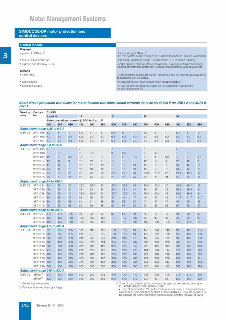
Siemens LV 10 · 20043/84
Motor Management Systems
SIMOCODE-DP motor protection and control devices
3
Short-circuit protection with fuses for motor feeders with short-circuit currents up to 50 kA at 690 V for 3RB1 2 and 3UF5 0, Part 1
1) Contactors mountable.
2) Pay attention to operating voltage.
3) Type of coordination and short-circuit protection devices according toIEC 60947-4-1/DIN VDE 660 Part 102:• Type of coordination "1": In the event of a short-circuit, the contactor or starter must not endanger persons or the installation. They do not have to be suitable for further operation without repair and the renewal of parts.
Control moduleDisplays
• green LED "Ready" Continuous light: "Ready"Off: “No control supply voltage" or "Function test not OK; device is disabled"
• red LED "General Fault" Continuous light/steady light: “Feeder fault”, e.g. overload tripping
• 3 green and 3 yellow LEDs Feeder-specific displays, freely-assignable, e.g. manual/automatic mode, tripping of thermistor protection, clockwise/counterclockwise rotation etc.
Buttons
• Test/Reset By pressing the Test/Reset button, the device can be reset following a trip or its functions can be tested
• Control keys For controlling the motor feeder, freely programmable
• System interface RS 232 as connection to the basic unit or expansion module andfor connection to a PC
Overloadrelay
Contac-tor
CLASS
5 and 10 15 20 25 30
Rated operational current Ie AC-3 in A at ... V
400 500 690 400 500 690 400 500 690 400 500 690 400 500 690
Adjustment range 1.25 to 6.3 A3UF5 00 3RT1 015 6.3 5 4 6.3 5 4 6.3 5 4 6.3 5 4 6.3 5 4
3RT1 016 6.3 6.3 5.2 6.3 6.3 5.2 6.3 6.3 5.2 6.3 6.3 5.2 6.3 6.3 5.2
3RT1 017 6.3 6.3 6.3 6.3 6.3 6.3 6.3 6.3 6.3 6.3 6.3 6.3 6.3 6.3 6.3
Adjustment range 6.3 to 25 A3UF5 01 3RT1 015 7 7 7 7 7
3RT1 016 9 6.5 9 6.5 9 6.5 9 6.5 9 6.5
3RT1 017 12 9 6.3 11 9 6.3 10 9 6.3 9.5 9 6.3 9 9 6.3
3RT10 24 12 12 9 12 12 9 12 12 9 12 12 9 12 12 9
3RT10 25 17 17 13 17 17 13 16 16 13 15 15 13 14 14 13
3RT10 26 25 18 13 18 18 13 16 16 13 15 15 13 14 14 13
3RT10 34 25 25 20 25 25 20 22.3 22.3 20 20.3 20.3 20.3 19.1 19.1 19.1
3RT10 35 25 25 24 25 25 24 25 25 24 25 25 24 25 25 24
Adjustment range 25 to 100 A3UF5 02 3RT10 34 32 32 20 25.5 25.5 20 22.3 22.3 20 20.3 20.3 20 19.1 19.1 19.1
3RT10 35 40 40 24 33 33 24 29.4 29.4 24 28 28 24 26.5 26.5 24
3RT10 36 50 50 24 38.5 38.5 24 32.7 32.7 24 29.4 29.4 24 26.5 26.5 24
3RT10 44 65 65 47 56 56 47 49 49 47 45 45 45 41.7 41.7 41.7
3RT10 45 80 80 58 61 61 58 53 53 53 47 47 47 45 45 45
3RT10 46 95 95 58 69 69 58 59 59 58 53 53 53 50 50 50
Adjustment range 50 to 205 A3UF5 03 3RT10 54 115 115 115 93 93 93 82 82 82 75 75 75 69 69 69
3RT10 55 150 150 150 122 122 122 107 107 107 98 98 98 90 90 90
3RT10 56 185 185 170 150 150 150 131 131 131 120 120 120 111 111 111
Adjustment range 125 to 500 A3UF5 04 3RT10 64 225 225 225 182 182 182 160 160 160 146 146 146 135 135 135
3RT10 65 265 265 265 215 215 215 188 188 188 172 172 172 159 159 159
3RT10 66 300 300 280 243 243 243 213 213 213 195 195 195 180 180 180
3RT10 75 400 400 400 324 324 324 284 284 284 260 260 260 240 240 240
3RT10 76 500 500 450 405 405 405 355 355 355 325 325 325 300 300 300
3RT12 64 225 225 225 225 225 225 225 225 225 194 194 194 173 173 173
3RT12 65 265 265 265 265 265 265 265 265 265 228 228 228 204 204 204
3RT12 66 300 300 300 300 300 300 300 300 300 258 258 258 231 231 231
3RT12 75 400 400 400 400 400 400 400 400 400 344 344 344 308 308 308
3RT12 76 500 500 500 500 500 500 500 500 500 430 430 430 385 385 385
Adjustment range 200 to 820 A3UF5 05 3TF681) 630 630 630 502 502 502 440 440 440 408 408 408 376 376 376
3TF691) 820 820 820 662 662 662 572 572 572 531 531 531 500 500 500
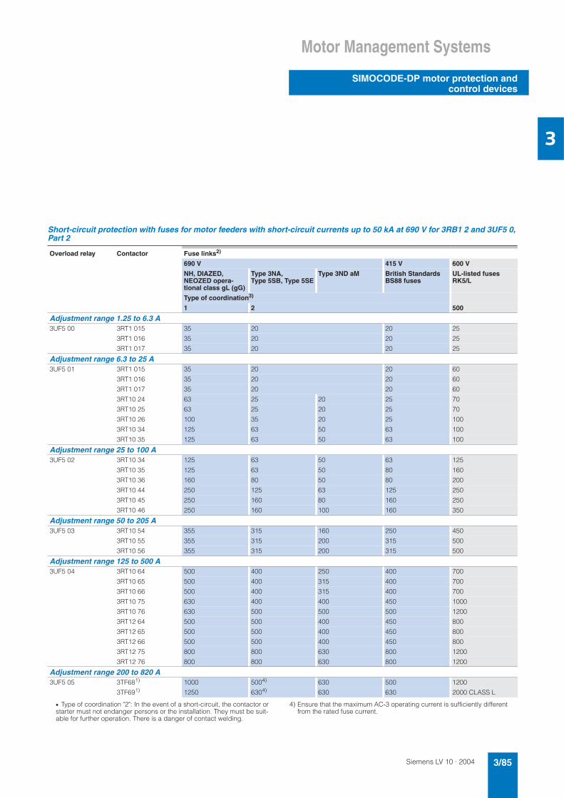
Siemens LV 10 · 2004 3/85
Motor Management Systems
SIMOCODE-DP motor protection andcontrol devices
3
Short-circuit protection with fuses for motor feeders with short-circuit currents up to 50 kA at 690 V for 3RB1 2 and 3UF5 0, Part 2
• Type of coordination "2": In the event of a short-circuit, the contactor or starter must not endanger persons or the installation. They must be suit-able for further operation. There is a danger of contact welding.
4) Ensure that the maximum AC-3 operating current is sufficiently different from the rated fuse current.
Overload relay Contactor Fuse links2)
690 V 415 V 600 V
NH, DIAZED, NEOZED opera-tional class gL (gG)
Type 3NA,Type 5SB, Type 5SE
Type 3ND aM British Standards BS88 fuses
UL-listed fusesRK5/L
Type of coordination3)
1 2 500
Adjustment range 1.25 to 6.3 A3UF5 00 3RT1 015 35 20 20 25
3RT1 016 35 20 20 25
3RT1 017 35 20 20 25
Adjustment range 6.3 to 25 A3UF5 01 3RT1 015 35 20 20 60
3RT1 016 35 20 20 60
3RT1 017 35 20 20 60
3RT10 24 63 25 20 25 70
3RT10 25 63 25 20 25 70
3RT10 26 100 35 20 25 100
3RT10 34 125 63 50 63 100
3RT10 35 125 63 50 63 100
Adjustment range 25 to 100 A3UF5 02 3RT10 34 125 63 50 63 125
3RT10 35 125 63 50 80 160
3RT10 36 160 80 50 80 200
3RT10 44 250 125 63 125 250
3RT10 45 250 160 80 160 250
3RT10 46 250 160 100 160 350
Adjustment range 50 to 205 A3UF5 03 3RT10 54 355 315 160 250 450
3RT10 55 355 315 200 315 500
3RT10 56 355 315 200 315 500
Adjustment range 125 to 500 A3UF5 04 3RT10 64 500 400 250 400 700
3RT10 65 500 400 315 400 700
3RT10 66 500 400 315 400 700
3RT10 75 630 400 400 450 1000
3RT10 76 630 500 500 500 1200
3RT12 64 500 500 400 450 800
3RT12 65 500 500 400 450 800
3RT12 66 500 500 400 450 800
3RT12 75 800 800 630 800 1200
3RT12 76 800 800 630 800 1200
Adjustment range 200 to 820 A3UF5 05 3TF681) 1000 5004) 630 500 1200
3TF691) 1250 6304) 630 630 2000 CLASS L
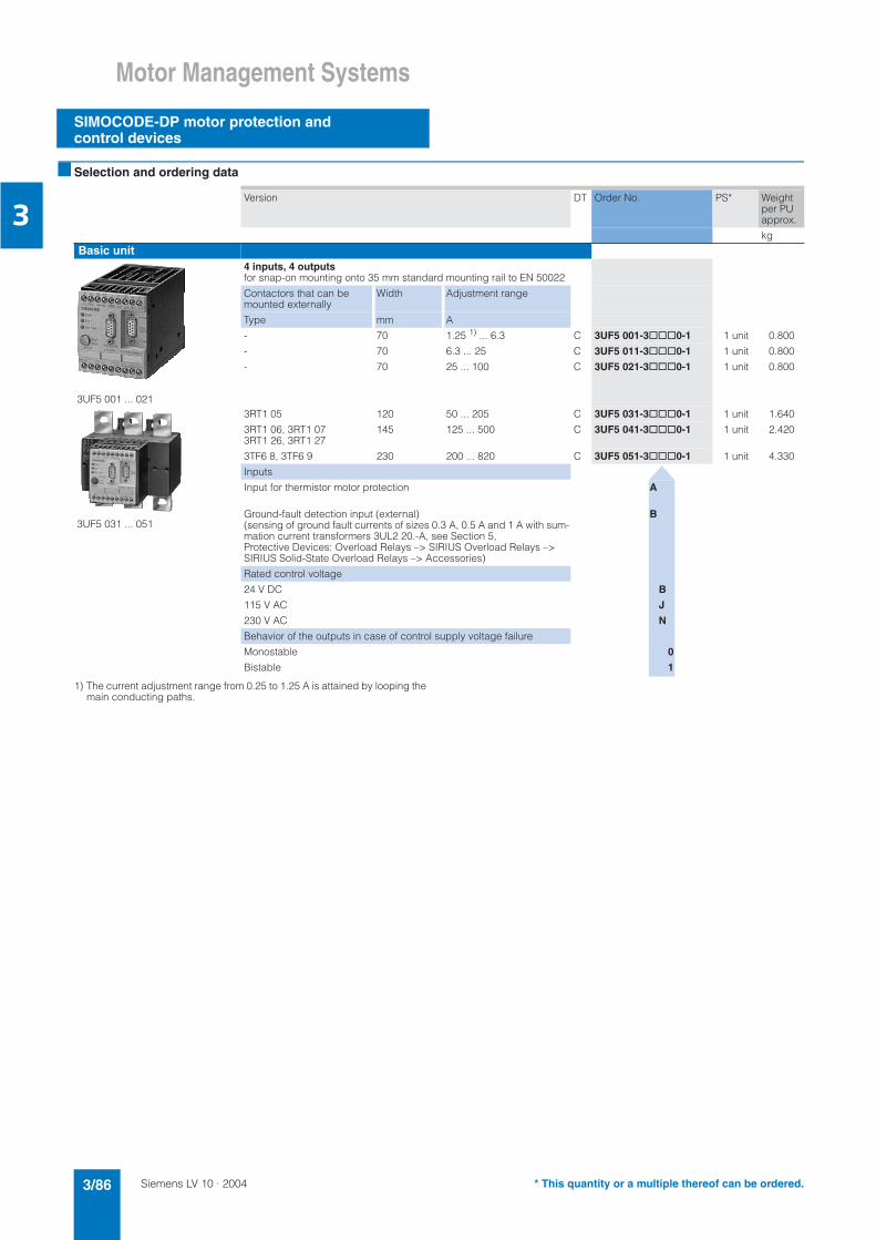
Siemens LV 10 · 20043/86
Motor Management Systems
SIMOCODE-DP motor protection and control devices
3
Selection and ordering data
1) The current adjustment range from 0.25 to 1.25 A is attained by looping the main conducting paths.
Version DT Order No. PS* Weight per PU approx.
kg
Basic unit
3UF5 001 ... 021
4 inputs, 4 outputs for snap-on mounting onto 35 mm standard mounting rail to EN 50022
Contactors that can be mounted externally
Width Adjustment range
Type mm A
- 70 1.25 1) ... 6.3 C 3UF5 001-3@@@0-1 1 unit 0.800
- 70 6.3 ... 25 C 3UF5 011-3@@@0-1 1 unit 0.800
- 70 25 ... 100 C 3UF5 021-3@@@0-1 1 unit 0.800
3UF5 031 ... 051
3RT1 05 120 50 ... 205 C 3UF5 031-3@@@0-1 1 unit 1.640
3RT1 06, 3RT1 073RT1 26, 3RT1 27
145 125 ... 500 C 3UF5 041-3@@@0-1 1 unit 2.420
3TF6 8, 3TF6 9 230 200 ... 820 C 3UF5 051-3@@@0-1 1 unit 4.330
Inputs
Input for thermistor motor protection A
Ground-fault detection input (external)(sensing of ground fault currents of sizes 0.3 A, 0.5 A and 1 A with sum-mation current transformers 3UL2 20.-A, see Section 5, Protective Devices: Overload Relays –> SIRIUS Overload Relays –> SIRIUS Solid-State Overload Relays –> Accessories)
B
Rated control voltage
24 V DC B
115 V AC J
230 V AC N
Behavior of the outputs in case of control supply voltage failure
Monostable 0
Bistable 1
* This quantity or a multiple thereof can be ordered.

Siemens LV 10 · 2004 3/87
Motor Management Systems
SIMOCODE-DP motor protection andcontrol devices
3
1) Start of delivery, please enquire.
Version DT Order No. PS* Weight per PU approx.
kg
Expansion module
Expansion module
8 inputs, 4 outputs for snap-on mounting on 35 mm standard mounting rail to EN 50022, external supply voltage for the inputs
AC 230 V A 3UF5 100-0AN00 1 unit 0.445
AC 115 V C 3UF5 100-0AJ00 1 unit 0.442
DC 24 V A 3UF5 100-0AB00 1 unit 0.422
Control module
Control module
For installation in the control cabinet doorcan be snapped onto basic unit or expansion module
A 3UF5 202-1AA00-1 1 unit 0.137
Configuration software
3UF57 710-0AA00-0
Win-SIMOCODE-DP/Professional
• Parameterization, control, visualization and testing:Via PROFIBUS DPV1 or via RS 232
• PC/PG requirement:Windows 95/98/2000/NT/ME or Windows XP
• PC/PG interface requirement:PROFIBUS system interface from Siemens or RS 232 with compatible 3RW2 920-1DA00 interface cable
• SIMOCODE-DP requirement:Delivery stage E10 (as of June 1998)
• Type of delivery:CD, English/German (selectable) incl. online Help andexample parameter files, single license
A 3UF5 710-0AA00-0 1 unit 0.230
3UF57 711-0AA00-0
Win-SIMOCODE-DP/Smart
• Parameterization, control, visualization and testing:Via RS 232
• PC/PG requirement:Windows 95/98/2000/NT/ME or Windows XP
• PC/PG interface requirement:RS 232 with compatible 3RW29 920-1DA00 interface cable
• Type of delivery:CD, English/German (selectable) incl. online Help andexample parameter files, single license
A 3UF5 711-0AA00-0 1 unit 0.231
OM-SIMOCODE-DPSTEP 7 Object Manager for integrating SIMOCODE-DP as S7 slave and for call of Win-SIMOCODE-DP/Professional from STEP 7
• Requirements:STEP 7, Version 4.0 or higher
• SIMOCODE-DP requirement:Delivery stage E10 (as of June 1998)
• Type of delivery:CD-ROM, English/German (selectable) incl. online Help,single license
A 3UF5 712-0AA00-0 1 unit 0.231
PCS 7 SIMOCODE-DP function modules
Function module for integrating SIMOCODE-DP in the PCS 7 user pro-gram and for visualizing SIMOCODE-DP-specific data in a faceplate.
• SIMOCODE-DP requirement:Delivery stage E10 and higher (since June 1998)
• Type of delivery:CD-ROM, English/German, single user license
• PCS 7 prerequisites:
- PCS7 Version 4.2 to 5.2 A 3UF5 720-0AA00-0 1 unit 0.240
- PCS 7 Version 6.0 1) A 3UF5 720-0AA10-0 1 unit 0.240
* This quantity or a multiple thereof can be ordered.

Siemens LV 10 · 20043/88
Motor Management Systems
SIMOCODE-DP motor protection and control devices
3
Version DT Order No. PS* Weight per PU approx.
kg
DocumentationSystem manual with description of communication via PROFIBUS DP and configuration example with token fee• German A 3UF5 700-0AA00-0 1 unit 0.841
• English D 3UF5 700-0AA00-1 1 unit 0.842
Connecting cable, installation material Connecting cable for PC communication via the RS 232 system interface, 5 m long
3RW2 920-1DA00 1 unit 0.176
3UF1 900-1A3UF1 900-1B3UF1 900-1C
3UF1 900-1D3UF1 900-1E
Connecting plug/connecting lead with 3UF5 9/3UF1 9 connectors
• For connecting the basic unit to the expansion unit, 9-pole,0.03 m tab connector shielded
A 3UF5 900-1AA00 1 unit 0.020
• For connecting the basic unit to the expansion unit oroperator module, 9-pole
- 0.5 m long, shielded plug 45° angular A 3UF1 900-1AA00 1 unit 0.076
- 2.0 m long, shielded plug 45° angular A 3UF1 900-1BA00 1 unit 0.161
- 2.5 m long, shielded plug 45° angular A 3UF1 900-1CA00 1 unit 0.190
- 0.5 m long, with flat plug, shielded A 3UF1 900-1DA00 1 unit 0.063
- 1.0 m long, with flat plug, shielded A 3UF1 900-1EA00 1 unit 0.092
• For connecting basic unit/expansion module to the control cabinet doorIt is possible to set parameters, operate and monitor using the PC from the control cabinet door, 9-pole
- 0.5 m long, with tab connector and socket, shielded A 3UF5 900-0AA00 1 unit 0.066
- 1.0 m long, with tab connector and socket, shielded A 3UF5 900-0BA00 1 unit 0.093
T-shaped terminal Terminal for bus connection to PROFIBUS DP - RS 485
A 3UF5 900-1GA00 1 unit 0.045
Bus termination Bus termination module with separate supply voltage for terminating the bus following the last unit on the bus line. Supply voltage:
AC 115/230 V A 3UF1 900-1KA00 1 unit 0.286
DC 24 V A 3UF1 900-1KB00 1 unit 0.192
* This quantity or a multiple thereof can be ordered.
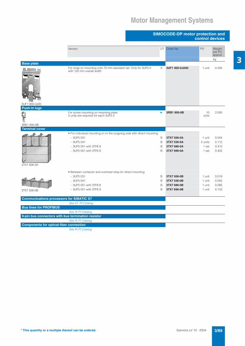
Siemens LV 10 · 2004 3/89
Motor Management Systems
SIMOCODE-DP motor protection andcontrol devices
3
Version DT Order No. PS* Weight per PU approx.
kg
Base plate
3UF1 900-0J00
For snap-on mounting onto 75 mm standard rail. Only for 3UF5 0 with 120 mm overall width
A 3UF1 900-0JA00 1 unit 0.200
Push-in lugs
3RB1 900-0B
For screw mounting on mounting plate2 units are required for each 3UF5 0
3RB1 900-0B 10units
2.000
Terminal cover
3TX7 506-0A
• For individual mounting or on the outgoing side with direct mounting
- 3UF5 031 B 3TX7 506-0A 1 unit 0.044
- 3UF5 041 B 3TX7 536-0A 2 units 0.112
- 3UF5 051 with 3TF6 8 B 3TX7 686-0A 1 set 0.410
- 3UF5 051 with 3TF6 9 B 3TX7 696-0A 1 set 0.402
• Between contactor and overload relay for direct mounting
3TX7 506-0B
- 3UF5 031 B 3TX7 506-0B 1 unit 0.019
- 3UF5 041 B 3TX7 536-0B 1 unit 0.055
- 3UF5 051 with 3TF6 8 B 3TX7 686-0B 1 unit 0.085
- 3UF5 051 with 3TF6 9 B 3TX7 696-0B 1 unit 0.103
Communications processors for SIMATIC S7See ST 70 Catalog
Bus lines for PROFIBUSSee IK PI Catalog
9-pin bus connectors with bus termination resistorSee IK PI Catalog
Components for optical-fiber connectionSee IK PI Catalog
* This quantity or a multiple thereof can be ordered.

Siemens LV 10 · 20043/90
Motor Management Systems
SIMOCODE-DP motor protection and control devices
3
Characteristics
Tripping characteristic for 3-pole loading
The current-time curves for 3-pole symmetrical load show the re-lationship between the release time from cold and multiples of the operational current.
If the device is pre-loaded with 100 % of the current setting, the tripping times are reduced.
Tripping characteristic for 2-pole loading
In the case of 2-pole loading (failure of one phase) or current un-balance > 40 % of the current setting, the tripping times are re-duced, because the heat generated due to the unbalanced loading of the motor rises.
Dimension drawings
3UF5 001, 3UF5 011 and 3UF5 021 basic units
3UF5 031, 3UF5 041 and 3UF5 051 basic units
'
*
+
, +---------------------
------------------
, +--
**#-*
**#--.&#/
'
*
+
, +---------------------
------------------
, +--
**#-*
**#--.&#/
!
"
#
$
$
$
%
%
%
! #

Siemens LV 10 · 2004 3/91
Motor Management Systems
SIMOCODE-DP motor protection andcontrol devices
3
3UF5 1 expansion module 3UF5 2 control module
Circuit diagrams
Reversing starter circuit with SIMOCODE-DP
Further circuit diagrams for the control functions overload, direct online starter, star-delta starter, pole reversing, Dahlander pole-changing circuit, solenoid valve, gate valve (servo drive) and SIKOSTART 3RW2 2 and a configuration example are included in the 3UF5 7 system manual.
!
"!# #
$
"
"
" %
"
!
!
#
%
%
%
!#
&
'('''
''
&(
'('('
('
(&
'
'''''
((
&)
(&'

Siemens LV 10 · 20043/92
Motor Management Systems
SIMOCODE-DP motor protection and control devices
3
Further information
System manual
For selection of equipment and for planning, it is recommended that the 3UF5 7 system manual is consulted (see Selection and ordering data page 3/88).
CD-ROM "SIMOCODE-DP, Intelligence at the Field Level"
Concise introduction to the system landscape of SIMOCODE-DP, including 3UF57 manual, Win-SIMOCODE-DP/Smart demo parameterization software, example circuit diagrams, etc.(Order No. E2001-D1140-P21S-X-7400)
Configuration course
Two-day configuration course for SIMOCODE-DP (device spec-trum, functions, communications capability, practical exercises). For further details and registration, please contact:• Tel: +49 (9131) 7-2 79 72 • Fax:+49 (9131) 7-2 81 72
Internet
You can find further information on the Internet at:
www.siemens.de/simocode-dp

Siemens LV 10 · 2004 3/93
Motor Management Systems
Current transformers for overload protection
3
Overview
The 3UF1 8 current transformers are protection transformers and are used for actuating overload relays. Protection transformers are designed to ensure proportional current transfer up to amultiple of the primary rated current.
The 3UF1 8 current transformers convert the maximum current of the corresponding operating range into the standard signal1 A secondary.
Technical specifications
1) With or without box terminal.
2) Conductor cross-sections for box terminals, see 3TF68 and 3TF69 contac-tors in section contactors and contactor combinations.
3) With max. conductor cross-section, a terminal cover for maintaining the phase spacing is required.
Climatic environmental conditionsAmbient temperature in °C
• Operation -25 ... +60
• Storage/transport -40 ... +85
Temperature change in °C/h
• Operation max. 10
• Storage/transport max. 20
Relative humidity in % 15 ... 95 (indoor, acc. to DIN 40040, no condensation)
Air pressure in hPa
• Operation 860 ... 1060
• Storage/transport 650 ... 1060
Contaminants in ppm
• SO2 0.5 (relative humidity ≤ 60 %, no condensation)
• H2S 0.1 (relative humidity ≤ 60 %, no condensation)
Mechanical environmental conditionsVibrations in Hz acc. to IEC 60068-2-6 10 ... 57 (for constant amplitude 0.15 nm)
57 ... 150 (for constant acceleration 2 g)
Shock to IEC 60068-2-27 12 shocks (half sine 15 g/11 ms)
Requirements acc. to IEC, DIN and VDEDegree of protection to IEC 60529 IP20
Rated insulation voltage in V acc.to IEC 60664
690/1000 (type-dependent)
Rating of the insulation in V (to UL/CSA) 600
Trip class acc. to IEC 60947-4-1 suitable from CLASS 5 to CLASS 30
Power loss per conducting path of the transformers
Operating range for setting ...
to the lower limit to the upper limit
A mW (mVA) mW (mVA)
• 3UF1 845 12.5 ... 50 33 (38) 570 (650)
• 3UF1 848 25 ... 100 110 (120) 1700 (1900)
• 3UF1 850 32 ... 130 135 (150) 2400 (2700)
• 3UF1 852 50 ... 200 170 (190) 2600 (2900)
• 3UF1 856 100 ... 400 450 (500) 6500 (7000)
• 3UF1 857 125 ... 500 850 (940) 13000 (15000)
• 3UF1 868-3F 160 ... 630 900 (1000) 17000 (19000)
• 3UF1 868-3G 205 ... 820 1400 (1600) 22000 (25000)
Conductor cross-sections (one or two conductors connectable)
Current transformers
on second-ary side
on primary side
3UF1 845 3UF1 8481) 3UF1 8501) 3UF1 852 3UF1 8563UF1 857
3UF1 868-3FA002)
3UF1 868-3GA002)
• Terminal screw M 3.5 For con. data see 3RT con-tactors in Part 2
For con. data see 3RT con-tactors in Part 2
For con. data see 3RT con-tactors in Part 2
M 8 M 10 M 10 M 12
• Solid in mm2 2 × 1.5 ... 2.5
- - - -
• Stranded in mm2 2 × 1.5 ... 2.5
- - - -
• Finely stranded without end sleeve in mm2 - - - - -
• Finely stranded with end sleeve in mm 2 2 × 1.5 - - - -
• Finely stranded with cable lug in mm2 - 35 ... 95 50 ... 2403) 50 ... 240 185 ... 240
• Stranded with cable lug in mm2 - 50 ... 120 70 ... 2403) 70 ... 240 185 ... 240
• Connecting bars in mm - 20 × 4 25 × 6.30 × 6
30 × 5 50 × 5
• Tightening torque in Nm 0.8 ... 1.4 10 ... 14 14 ... 24 14 ... 24 14 ... 24
• Tightening torque in lb.in 7 ... 12 89 ... 124 124 ... 210 124 ... 210 124 ... 210
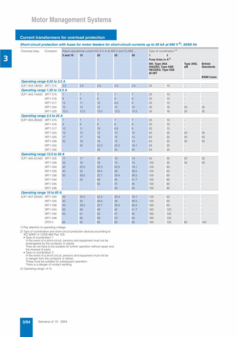
Siemens LV 10 · 20043/94
Motor Management Systems
Current transformers for overload protection
3
Short-circuit protection with fuses for motor feeders for short-circuit currents up to 50 kA at 690 V 4), 50/60 Hz
1) Pay attention to operating voltage.
2) Type of coordination and short-circuit protection devices according to IEC 60947-4-1/VDE 660 Part 102:• Type of coordination 1
In the event of a short-circuit, persons and equipment must not beendangered by the contactor or starter.They do not have to be suitable for further operation without repair andthe renewal of parts.
• Type of coordination 2 In the event of a short-circuit, persons and equipment must not be in danger from the contactor or starter.These must be suitable for subsequent operation. There is a danger of contact welding.
3) Operating range +5 %.
Overload relay Contactor Rated operational current AC-3 in A at 400 V and CLASS ... Type of coordination 2)
5 and 10 15 20 25 30 1 2
Fuse links in A1)
NH, Type 3NA DIAZED, Type 5SB NEOZED, Type 5SE gL/gG
Type 3ND, aM
British Standards
BS88 fuses
Operating range 0.25 to 2.5 A3UF1 843-1BA00 3RT1 015 2.5 2.5 2.5 2.5 2.5 25 10 - -
Operating range 1.25 to 12.5 A3UF1 843-1AA00 3RT1 015 7 7 7 7 7 25 10 - -
3RT1 016 9 9 9 9 9 25 10 - -
3RT1 017 12 11 10 9.5 9 25 10 - -
3RT1 024 12 12 12 12 12 35 16 20 35
3RT1 025 12.5 12.5 12.5 12.5 12.5 35 16 20 35
Operating range 2.5 to 25 A3UF1 843-2BA00 3RT1 015 7 7 7 7 7 25 10 - -
3RT1 016 9 9 9 9 9 25 10 - -
3RT1 017 12 11 10 9.5 9 25 10 - -
3RT1 024 12 12 12 12 12 63 25 20 35
3RT1 025 17 17 16 15 14 63 25 20 35
3RT1 026 25 18 16 15 14 63 25 35 50
3RT1 034 - 25 22.3 20.3 19.1 63 25 - -
3RT1 035 - - 25 25 25 63 25 - -
Operating range 12.5 to 50 A3UF1 845-2CA00 3RT1 025 17 17 16 15 14 63 25 20 35
3RT1 026 25 18 16 15 14 100 35 35 50
3RT1 034 32 25.5 22.3 20.3 19.1 100 63 - -
3RT1 035 40 33 29.4 28 26.5 100 63 - -
3RT1 036 50 38.5 32.7 29.4 26.5 100 80 - -
3RT1 044 - 50 49 45 41.7 100 80 - -
3RT1 045 - - 50 47 45 100 80 - -
3RT1 046 - - - 50 50 100 80 - -
Operating range 16 to 65 A3UF1 847-2DA00 3RT1 034 32 25.5 22.3 20.3 19.1 125 63 - -
3RT1 035 40 33 29.4 28 26.5 125 63 - -
3RT1 036 50 38.5 32.7 29.4 26.5 160 80 - -
3RT1 044 65 56 49 45 41.7 160 125 - -
3RT1 045 65 61 53 47 45 160 125 - -
3RT1 046 - 65 59 53 50 160 125 - -
3TF5 0 65 65 65 65 65 160 125 80 100

Siemens LV 10 · 2004 3/95
Motor Management Systems
Current transformers for overload protection
3
1) Pay attention to operating voltage.
2) Type of coordination and short-circuit protection devices according to IEC 60947-4-1/VDE 660 Part 102:• Type of coordination 1
In the event of a short-circuit, persons and equipment must not be indanger from the contactor or starter.They do not have to be suitable for further operation without repair and the renewal of parts.
• Type of coordination 2 In the event of a short-circuit, persons and equipment must not be indanger from the contactor or starter.These must be suitable for subsequent operation. There is a danger of contact welding.
Overload relay Contactor Rated operating current AC-3 in A at 400 V and CLASS ... Type of coordination 2)
5 and 10 15 20 25 30 1 2
Fuse links in A1)
NH, Type 3NA DIAZED, Type 5SB NEOZED, Type 5SE gL/gG
Type 3ND, aM
British Standards
BS88 fuses
Operating range 25 to 100 A3UF1 848 -2EA00 3RT1 044 65 65 49 45 41.7 250 125 - -
3RT1 045 80 61 53 47 45 250 160 - -
3RT1 046 95 69 59 53 50 250 160 - -
3RT1 054 100 93 82 75 69 250 160 125 125
3RT1 055 - 100 100 98 90 250 160 125 125
3RT1 056 - - - 100 100 250 160 125 125
Operating range 32 to 130 A3UF1 850-3AA00 3RT1 044 65 56 49 45 41.7 250 125 - -
3RT1 045 80 61 53 47 45 250 160 - -
3RT1 046 95 69 59 53 50 250 160 - -
3RT1 054 115 93 82 75 69 315 224 160 160
3RT1 055 130 122 107 98 90 315 224 160 160
3RT1 056 - 130 130 120 111 315 224 160 160
3RT1 064 - - - 130 130 315 224 160 160
Operating range 50 to 200 A3UF1 852-3BA00 3RT1 054 115 93 82 75 69 355 224 160 160
3RT1 055 150 122 107 98 90 355 224 160 200
3RT1 056 185 150 131 120 111 355 224 160 200
3RT1 064 200 182 160 146 135 355 224 160 200
3RT1 065 - 200 188 172 159 355 224 160 200
3RT1 066 - - 200 195 180 355 224 160 200
3RT1 075 - - - 200 200 355 224 160 200
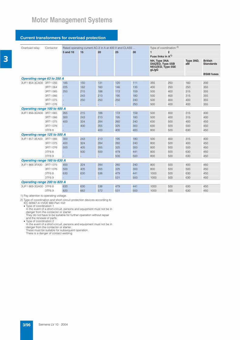
Siemens LV 10 · 20043/96
Motor Management Systems
Current transformers for overload protection
3
1) Pay attention to operating voltage.
2) Type of coordination and short-circuit protection devices according to IEC 60947-4-1/VDE 660 Part 102:• Type of coordination 1
In the event of a short-circuit, persons and equipment must not be indanger from the contactor or starter.They do not have to be suitable for further operation without repair and the renewal of parts.
• Type of coordination 2 In the event of a short-circuit, persons and equipment must not be in danger from the contactor or starter.These must be suitable for subsequent operation. There is a danger of contact welding.
Overload relay Contactor Rated operating current AC-3 in A at 400 V and CLASS ... Type of coordination 2)
5 and 10 15 20 25 30 1 2
Fuse links in A1)
NH, Type 3NA DIAZED, Type 5SB NEOZED, Type 5SE gL/gG
Type 3ND, aM
British Standards
BS88 fuses
Operating range 63 to 250 A3UF1 854-3CA00 3RT1 056 185 150 131 120 111 355 250 160 200
3RT1 064 225 182 160 146 135 400 250 250 355
3RT1 065 250 215 188 172 159 500 400 315 355
3RT1 066 - 243 213 195 180 500 400 315 355
3RT1 075 - 250 250 250 240 500 400 400 355
3RT1 076 - - - - 250 500 400 400 355
Operating range 100 to 400 A3UF1 856-3DA00 3RT1 065 265 215 188 172 159 500 400 315 400
3RT1 066 300 243 213 195 180 500 400 315 400
3RT1 075 400 324 284 260 240 630 500 400 450
3RT1 076 - 400 355 325 300 630 500 500 450
3TF6 8 - - 400 400 400 800 500 630 450
Operating range 125 to 500 A3UF1 857-3EA00 3RT1 066 300 243 213 195 180 500 400 315 400
3RT1 075 400 324 284 260 240 800 500 400 450
3RT1 076 500 405 355 325 300 800 500 500 450
3TF6 8 - 500 500 479 441 800 500 630 450
3TF6 9 - - - 500 500 800 500 630 450
Operating range 160 to 630 A3UF1 868-3FA00 3RT1 075 400 324 284 260 240 800 500 400 450
3RT1 076 500 405 355 325 300 800 500 500 450
3TF6 8 630 630 536 479 441 1000 500 630 450
3TF6 9 - - - 531 500 1000 500 630 450
Operating range 200 to 820 A3UF1 869-3GA00 3TF6 8 630 630 536 479 441 1000 500 630 450
3TF6 9 820 662 572 531 500 1000 500 630 450

Siemens LV 10 · 2004 3/97
Motor Management Systems
Current transformers for overload protection
3
Selection and ordering data
1) The following adjustment ranges for the protection of EEx e motors areapplicable:3UF1 843-1BA00, 0.25 ... 1.25 A3UF1 843-2AA00, 1.25 ... 6.3 A3UF1 843-2BA00, 2.5 ... 12.5 A
Note: Application in the SIMOCODE-DP system when using the control functions pole reversal and Dahlander circuit. Please note the configuring aids in the 3UF5 7 system manual.
Version DT Order No. PS* Weight per PU approx.
kg
Current transformers for stand-alone installation
3UF1 843
for snap-on and screw mounting, suitable for snapping on to 35 mm standard mounting rails accord. to EN 50022
Operating range
A
0.25 ... 2.5 1) A 3UF1 843-1BA00 1 unit 0.4881.25 ... 12.5 1) D 3UF1 843-2AA00 1 unit 0.4852.5 ... 25 1) D 3UF1 843-2BA00 1 unit 0.49012.5 ... 50 D 3UF1 845-2CA00 1 unit 0.69416 ... 65 D 3UF1 847-2DA00 1 unit 1.18025 ... 100 D 3UF1 848-2EA00 1 unit 1.230
Current transformers for mounting on contactors and stand-alone installation
3UF1 868
for screw mounting
Operating range
A32 ... 130 D 3UF1 850-3AA00 1 unit 1.74050 ... 200 D 3UF1 852-3BA00 1 unit 1.89063 ... 250 D 3UF1 854-3CA00 1 unit 3.610100 ... 400 D 3UF1 856-3DA00 1 unit 3.850125 ... 500 D 3UF1 857-3EA00 1 unit 4.130160 ... 630 D 3UF1 868-3FA00 1 unit 7.780205 ... 820 D 3UF1 868-3GA00 1 unit 8.920
Terminal covers
3TX7 466-0A
for converter/contactor combinations and stand-alone mounting forconverters with and without box terminals(cover required per connection side)
3UF1 845 B 3TX7 446-0A 1 unit 0.0063UF1 848 B 3TX7 466-0A 1 unit 0.0353UF1 850, 3UF1 852 B 3TX7 506-0A 1 unit 0.0443UF1 854 ... 3UF1 857 B 3TX7 536-0A 2 units 0.1123UF1 868-3FA00 B 3TX7 686-0A 1 set 0.4103UF1 868-3GA00 B 3TX7 696-0A 1 set 0.402
for covering the screw connection for direct mounting on contactor (one cover required per contactor/converter combination)
3UF1 848 C 3TX7 466-0B 1 unit 0.0133UF1 850, 3UF1 852 B 3TX7 506-0B 1 unit 0.0193UF1 854 ... 3UF1 857 B 3TX7 536-0B 1 unit 0.0553UF1 868-3FA00 B 3TX7 686-0B 1 unit 0.0853UF1 868-3GA00 B 3TX7 696-0B 1 unit 0.103
Box terminal blocksfor stand-alone installation
3UF1 847, 3UF1 848 B 3TX7 460-0E 1 unit 0.0933UF1 850 B 3TX7 500-0E 1 unit 0.187
* This quantity or a multiple thereof can be ordered.
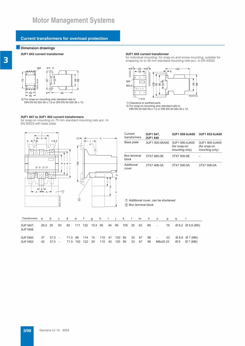
Siemens LV 10 · 20043/98
Motor Management Systems
Current transformers for overload protection
3
Dimension drawings
3UF1 843 current transformer 3UF1 845 current transformerfor individual mounting: for snap-on and screw mounting, suitable for snapping on to 35 mm standard mounting rails acc. to EN 50022
3UF1 847 to 3UF1 852 current transformers for snap-on mounting on 75 mm standard mounting rails acc. to EN 50023 with base plate
352)
75
M4
3545
NS
A0_
0015
5
6 94
9
87 56 89
2) For snap-on mounting onto standard rails to DIN EN 50 022-35 x 7,5 or DIN EN 50 022-35 x 15.
4,5
358095
102
NSA00156
56 88
6 5545
61) 1)
M4
M3,5 108
6
2)
1) Clearance to earthed parts.2) For snap-on mounting onto standard rails to DIN EN 50 022-35 x 7,5 or DIN EN 50 022-35 x 15.
&
"
!
#
! # & '
$ $ ( ) *
$ $ ( ) *
) + $ $ ( ) *
, ! ! - ' . ! ' ,
/ ! + , ' !
0 1 ' ' ,
, ' . ! ' ' .
! " # $ %
! " # #
! " # & ' ( ! " # & ' (
/ . # , 2 3
( ! ' . # !
! 1 , ! 4 *
3
( ! ' . # !
! 1 , ! 4 *
/ ! + , '
!
5 6 7 5 6 7 %
, !
! - '
5 6 5 6 5 6
5 ' . ! ' ' .

Siemens LV 10 · 2004 3/99
Motor Management Systems
Current transformers for overload protection
3
3UF1 854 to 3UF1 857 current transformers
/"
! ' )
5 ' . ! ' ' .

Siemens LV 10 · 20043/100
Motor Management Systems
Current transformers for overload protection
3
3UF1 868-3FA00, 3UF1 868-3GA00 current transformersfor 3TF6 8 contactors
NSA0_001590,5
4015
170
230
74
230100
28
232
220
210
174
140
15
12
7070
105
c
a
b
gfe
d
12
a b c d e f g
390 398 30 5 145 175 420 410 408 40 8 155 195 450
14 for M 12
14 for M 12
Contactors
3TF683TF68
Transformers
3UF18 68-3FA003UF18 68-3GA00

Siemens LV 10 · 2004 3/101
LOGO! Logic Modules
General data
3
Overview
The compact, user-friendly, and low-cost solution for simple control tasks• Compact, user-friendly, can be used universally without acces-
sories.• "All in one": the display and operator panel are integrated.• 34 different functions can be linked at a press of a button or
with PC software; up to 130 times in total• Functions can be changed simply via buttons; no complicated
rewiring
Area of application
The LOGO! logic module is the user-friendly, low-cost solution for simple control tasks.
LOGO! is universally applicable, e.g.:• Building installation and wiring (lighting, shutters, awnings,
doors, access control, barriers, ventilation systems, etc.)• Controlgear cubicle installation• Machine and device construction (pumps, small presses,
compressors, hydraulic lifts, conveyors ...) • Special controls for conservatories and greenhouses• Signal preprocessing for other controllers
The LOGO! Modular logic modules can be expanded easily for each application.
Marine approvals
American Bureau of Shipping, Bureau Veritas, Det NorskeVeritas, Germanischer Lloyd, Lloyds Register of Shipping, Polski Rejestr Statków
Design
LOGO! The modular design is available in different variants for different supply voltages (DC 12 V, DC 24 V; AC 24 V, DC 115/230 V, AC 115/230 V):• Basic variants• Low-cost pure variants without operator control and display
panels
The LOGO! variants have the following distinguishing character-istics:• R: Relay output• C: Clock/time switch• o: Without display
LOGO! is simple• Operator control panel and front panel in one unit; no other
tools are necessary• Non-volatile storage of control program and setpoints (e.g.
times) in integrated EEPROM
LOGO! is space-saving• e. g. LOGO! 230RC: 72 x 90 x 55 mm (W x H x D)• Fitted mounting in the distribution box (same mounting dimen-
sions as the ground-fault circuit interrupter)
LOGO! offers maximum flexibility and is universal• Expandability;
depending on the application, additional expansion modules can be connected.
LOGO! is communication-capable• Optional communication modules support interfacing to AS-In-
terface and instabus EIB networks
Functions
LOGO! is "All in one"
The display and operator panel are integrated. It is compact, easy to use, low cost and can be used universally without the need for any accessories. 34 different functions can be used in each LOGO! They are simply linked by pressing a button or by means of PC software. It is therefore possible to adapt it to changes quickly in the future without the need for expensiverewiring.
LOGO! is simple• Integrated basic functions (e.g. AND, OR) and special func-
tions (e.g. timers, counters, latching relay) of the electronics• Program generation simply by combining stored functions at
the press of a key or PC software• Easy-to-use and simple duplication of the control program with
an optional program module
LOGO! offers maximum flexibility and is universal• Easy modification by reconnecting the functions at a press of a
key; no need for time-consuming rewiring• Optional operation from the PC; For creating, simulating, online
testing, and archiving the control program on the PC, including documentation facility

Siemens LV 10 · 20043/102
LOGO! Logic Modules
LOGO! modular basic variants
3
Overview
The space-saving basic variants• With interface for connecting extension modules
Design
• Relay outputs with up to 10 A output current (not LOGO! 24)• Integrated front panel with background illumination
(4 x 12 characters)• Integrated operator control panel• Integrated basic and special functions• Integrated EEPROM for storing control program and setpoints• Optional programming module• Integrated clock with automatic summertime/wintertime
changeover (not LOGO! 24)• 130 function blocks can be combined• 8 digital inputs, 4 digital outputs• 2 inputs as analog inputs for DC 12/24 V versions (0 to 10 V);
inputs can also be used as digitally• 2 inputs for counting up to 2 kHz can be used
(for DC variants only)• Interface for connecting expansion modules, max. 24 digital in-
puts, 16 digital outputs and 8 analog inputs can be addressed
Functions
• Basic functions:- AND, OR, NOT, NAND, NOR, XOR- Positive/negative edge evaluation
• Special functions:- ON delay- Latching ON delay- OFF delay- Pulse relay- Latching relay- Clock-pulse relay- Counter (forward/backward)- Time switch- Interval time-delay relay- Working hour meter- Threshold switch- Asynchronous pulse encoder- Yearly timer switch- Easy-to-use switch function- Random generator- Staircase lighting function acc. to DIN 18015-2- Edge-triggered interval time-delay relay- Combined ON/OFF delay- Analog comparator- Analog threshold switch- Analog delta threshold switch- Analog watchdog- Analog amplifier- Text and variable display- Shift register- Softkey function
• 24 flags (including start-up flag)• Integrated retentivity• Password protection
Optional functions • Additional know-how protection with the optional program
module

Siemens LV 10 · 2004 3/103
LOGO! Logic Modules
LOGO! modular basic variants
3
Selection and ordering data
Version DT Order No. PS* Weight per PU approx.
kg
LOGO! logic module 24 A 6ED1 052-1CC00-0BA4 1 unit 0.189Supply voltage DC 24 V8 digital inputs DC 24 V, of which 2 can be used as analog inputs (0 to 10 V),4 digital outputs DC 24 V, 0.3 A; 130 function blocks can be combined,modular expandability
LOGO! logic module 12/24RC A 6ED1 052-1MD00-0BA4 1 unit 0.220Supply voltage DC 12/24 V, 8 digital inputs DC 12/ 24 V, of which 2 can be used as analog inputs (0 to 10 V), 4 relay outputs 10 A, Integrated time switch; 130 function blocks can be combined,modular expandability
LOGO! logic module 24RC A 6ED1 052-1HB00-0BA4 1 unit 0.228Supply voltage AC/DC 24 V, 8 digital inputs AC/DC 24 V, 4 relay outputs 10 A, Integrated time switch; 130 function blocks can be combined,modular expandability
LOGO! logic module 230RC A 6ED1 052-1FB00-0BA4 1 unit 0.232Supply voltage AC/DC 115/230 V, 8 digital inputs AC/DC 115/230 V, 4 relay outputs 10 A, integrated time switch; 130 function blocks can be combined,modular expandability
AccessoriesLOGO! Manual• German A 6ED1 050-1AA00-0AE5 1 unit 0.353• English A 6ED1 050-1AA00-0BE5 1 unit 0.359• French X 6ED1 050-1AA00-0CE5 1 unit 0.353• Spanish X 6ED1 050-1AA00-0DE5 1 unit 0.353• Italian X 6ED1 050-1AA00-0EE5 1 unit 0.353
LOGO! Memory card A 6ED1 056-5CA00-0BA0 1 unit 0.003for copying with know-how protection
LOGO! Soft Comfort V4.0 A 6ED1 058-0BA00-0YA0 1 unit 0.100for programming on the PC in LAD/FBD; runs on Windows 95, Linux, MAC OSX;on CD-ROM
LOGO! Soft Comfort Upgrade A 6ED1 058-0CA00-0YE0 1 unit 0.100for V1.0 and higher on V4.0
LOGO! PC cable A 6ED1 057-1AA00-0BA0 1 unit 0.168for transferring programs between LOGO! and PC
LOGO! News Box, 12/24 Vcontains LOGO! 12/24RC, LOGO! PC cable, LOGO!Soft Comfort, Tips&Tricks manual, screw driver, information material• German A 6ED1 057-3BA00-0AA3 1 unit 2.200• English A 6ED1 057-3BA00-0BA3 1 unit 2.200
LOGO! News Box, 230Vcontains LOGO! 230RC, LOGO! PC cable, LOGO!Soft Comfort, Tips&Tricks manual,screw driver, information material• German A 6ED1 057-3AA00-0AA8 1 unit 2.200• English A 6ED1 057-3AA00-0BA8 1 unit 2.340
* This quantity or a multiple thereof can be ordered.
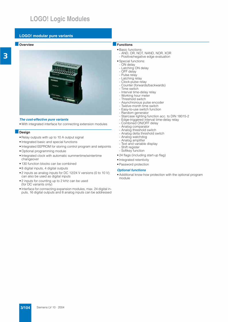
Siemens LV 10 · 20043/104
LOGO! Logic Modules
LOGO! modular pure variants
3
Overview
The cost-effective pure variants• With integrated interface for connecting extension modules
Design
• Relay outputs with up to 10 A output signal • Integrated basic and special functions• Integrated EEPROM for storing control program and setpoints• Optional programming module• Integrated clock with automatic summertime/wintertime
changeover• 130 function blocks can be combined• 8 digital inputs, 4 digital outputs• 2 inputs as analog inputs for DC 12/24 V versions (0 to 10 V);
can also be used as digital inputs• 2 inputs for counting up to 2 kHz can be used
(for DC variants only)• Interface for connecting expansion modules, max. 24 digital in-
puts, 16 digital outputs and 8 analog inputs can be addressed
Functions
• Basic functions:- AND, OR, NOT, NAND, NOR, XOR- Positive/negative edge evaluation
• Special functions:- ON delay- Latching ON delay- OFF delay- Pulse relay- Latching relay- Clock-pulse relay- Counter (forwards/backwards)- Time switch- Interval time-delay relay- Working hour meter- Threshold switch- Asynchronous pulse encoder- Twelve-month time switch- Easy-to-use switch function- Random generator- Staircase lighting function acc. to DIN 18015-2- Edge-triggered interval time-delay relay- Combined ON/OFF delay- Analog comparator- Analog threshold switch- Analog delta threshold switch- Analog watchdog- Analog amplifier- Text and variable display- Shift register- Softkey function
• 24 flags (including start-up flag)• Integrated retentivity• Password protection
Optional functions • Additional know-how protection with the optional program
module

Siemens LV 10 · 2004 3/105
LOGO! Logic Modules
LOGO! modular pure variants
3
Selection and ordering data
Version DT Order No. PS* Weight per PU approx.
kg
LOGO! logic module 24o A 6ED1 052-2CC00-0BA4 1 unit 0.172Supply voltage DC 24 V,8 digital inputs DC 24 V, of which 2 can be used as analog inputs (0 to 10 V),4 digital outputs DC 24 V, 0.3 A;Without display and keyboard;130 function blocks can be combined,modular expandability
LOGO! logic module 12/24RCo A 6ED1 052-2MD00-0BA4 1 unit 0.216Supply voltage DC 12/24 V, 8 digital inputs DC12/ 24 V, of which 2 can be used as analog inputs (0 to 10 V), 4 relay outputs 10 A, Integrated time switch; Without display and keyboard;130 function blocks can be combined,modular expandability
LOGO! logic module 24RCo A 6ED1 052-2HB00-0BA4 1 unit 0.218Supply voltage AC/DC 24 V, 8 digital inputs AC/DC 24 V, 4 relay outputs 10 A, Integrated time switch; Without display and keyboard;130 function blocks can be combined,modular expandability
LOGO! logic module 230RCo A 6ED1 052-2FB00-0BA4 1 unit 0.221Supply voltage AC/DC 115/230 V, 8 digital inputs AC/DC 115/230 V, 4 relay outputs 10 A, integrated time switch; Without display and keyboard;130 function blocks can be combined,modular expandability
AccessoriesLOGO! Manual• German A 6ED1 050-1AA00-0AE5 1 unit 0.353• English A 6ED1 050-1AA00-0BE5 1 unit 0.359• French X 6ED1 050-1AA00-0CE5 1 unit 0.353• Spanish X 6ED1 050-1AA00-0DE5 1 unit 0.353• Italian X 6ED1 050-1AA00-0EE5 1 unit 0.353
LOGO! Memory card A 6ED1 056-5CA00-0BA0 1 unit 0.003for copying with know-how protection
LOGO! Soft Comfort V4.0 A 6ED1 058-0BA00-0YA0 1 unit 0.100for programming on the PC in LAD/FBD; runs on Windows 95, Linux, MAC OSX;on CD-ROM
LOGO! Soft Comfort Upgrade A 6ED1 058-0CA00-0YE0 1 unit 0.100for V1.0 and higher on V4.0
LOGO! PC cable A 6ED1 057-1AA00-0BA0 1 unit 0.168for transferring programs between LOGO! and PC
LOGO! News Box, 12/24 Vcontains LOGO! 12/24RC, LOGO! PC cable, LOGO!Soft Comfort, Tips&Tricks manual, screw driver, information material• German A 6ED1 057-3BA00-0AA3 1 unit 2.200• English A 6ED1 057-3BA00-0BA3 1 unit 2.200
LOGO! News Box, 230 Vcontains LOGO! 230RC, LOGO! PC cable, LOGO!Soft Comfort, Tips&Tricks manual,screw driver, information material• German A 6ED1 057-3AA00-0AA8 1 unit 2.200• English A 6ED1 057-3AA00-0BA8 1 unit 2.340
* This quantity or a multiple thereof can be ordered.
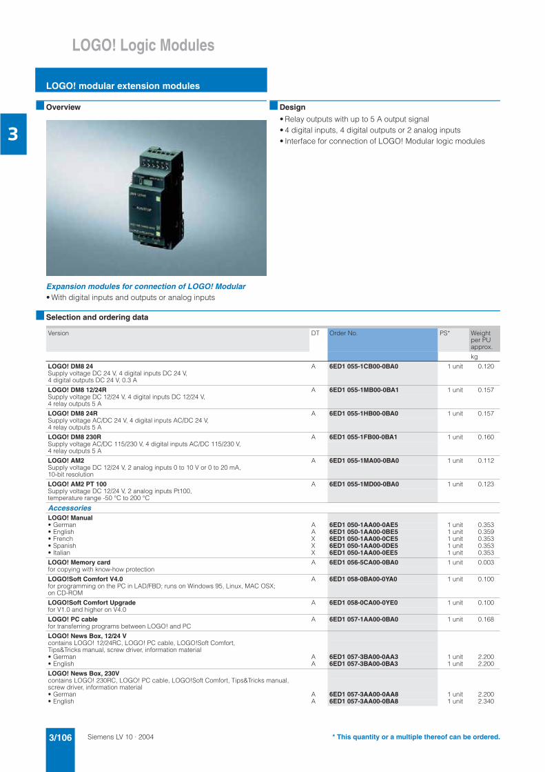
Siemens LV 10 · 20043/106
LOGO! Logic Modules
LOGO! modular extension modules
3
Overview
Expansion modules for connection of LOGO! Modular• With digital inputs and outputs or analog inputs
Design
• Relay outputs with up to 5 A output signal • 4 digital inputs, 4 digital outputs or 2 analog inputs• Interface for connection of LOGO! Modular logic modules
Selection and ordering data
Version DT Order No. PS* Weight per PU approx.
kg
LOGO! DM8 24 A 6ED1 055-1CB00-0BA0 1 unit 0.120Supply voltage DC 24 V, 4 digital inputs DC 24 V, 4 digital outputs DC 24 V, 0.3 A
LOGO! DM8 12/24R A 6ED1 055-1MB00-0BA1 1 unit 0.157Supply voltage DC 12/24 V, 4 digital inputs DC 12/24 V, 4 relay outputs 5 A
LOGO! DM8 24R A 6ED1 055-1HB00-0BA0 1 unit 0.157Supply voltage AC/DC 24 V, 4 digital inputs AC/DC 24 V, 4 relay outputs 5 A
LOGO! DM8 230R A 6ED1 055-1FB00-0BA1 1 unit 0.160Supply voltage AC/DC 115/230 V, 4 digital inputs AC/DC 115/230 V, 4 relay outputs 5 A
LOGO! AM2 A 6ED1 055-1MA00-0BA0 1 unit 0.112Supply voltage DC 12/24 V, 2 analog inputs 0 to 10 V or 0 to 20 mA, 10-bit resolution
LOGO! AM2 PT 100 A 6ED1 055-1MD00-0BA0 1 unit 0.123Supply voltage DC 12/24 V, 2 analog inputs Pt100, temperature range -50 °C to 200 °C
AccessoriesLOGO! Manual• German A 6ED1 050-1AA00-0AE5 1 unit 0.353• English A 6ED1 050-1AA00-0BE5 1 unit 0.359• French X 6ED1 050-1AA00-0CE5 1 unit 0.353• Spanish X 6ED1 050-1AA00-0DE5 1 unit 0.353• Italian X 6ED1 050-1AA00-0EE5 1 unit 0.353
LOGO! Memory card A 6ED1 056-5CA00-0BA0 1 unit 0.003for copying with know-how protection
LOGO!Soft Comfort V4.0 A 6ED1 058-0BA00-0YA0 1 unit 0.100for programming on the PC in LAD/FBD; runs on Windows 95, Linux, MAC OSX;on CD-ROM
LOGO!Soft Comfort Upgrade A 6ED1 058-0CA00-0YE0 1 unit 0.100for V1.0 and higher on V4.0
LOGO! PC cable A 6ED1 057-1AA00-0BA0 1 unit 0.168for transferring programs between LOGO! and PC
LOGO! News Box, 12/24 Vcontains LOGO! 12/24RC, LOGO! PC cable, LOGO!Soft Comfort, Tips&Tricks manual, screw driver, information material• German A 6ED1 057-3BA00-0AA3 1 unit 2.200• English A 6ED1 057-3BA00-0BA3 1 unit 2.200
LOGO! News Box, 230Vcontains LOGO! 230RC, LOGO! PC cable, LOGO!Soft Comfort, Tips&Tricks manual,screw driver, information material• German A 6ED1 057-3AA00-0AA8 1 unit 2.200• English A 6ED1 057-3AA00-0BA8 1 unit 2.340
* This quantity or a multiple thereof can be ordered.

Siemens LV 10 · 2004 3/107
LOGO! Logic Modules
LOGO! modular communications modules
3
Overview
Expansion module for the LOGO! basic variants• For communication between the LOGO! master and external
EIB components via EIB
Area of application
The CM EIB/KNX communication module allows communication between the LOGO! master and external EIB components via EIB. The module can be used to integrate LOGO! into an EIBsystem.
The module is connected to the LOGO! basic variants as anexpansion module.
Design
• Up to 16 digital inputs (virtual)• Up to 12 digital outputs (virtual)• Up to 8 analog inputs (virtual) • For mounting onto 35 mm standard rail• Width: 2 modular widths
Functions
• For communication between the LOGO! master and external EIB components via EIB
• Stations on the EIB;allow LOGO! to communicate with other EIB components by exchanging EIB message frames
• Output of the current states of the configured EIB stations for LOGO!;the control can combine these with the help of its logicalfunctions and timers.
• Parameters can be set, changed or combined quickly aneasily using LOGO! without the need for a programmingdevice.
Selection and ordering data
Version DT Order No. PS* Weight per PU approx.
kg
LOGO! communication module CM EIB KNX B 6BK1 700-0BA00-0AA0 1 unit 0.050for connection to EIB, supply voltage DC 24 V
* This quantity or a multiple thereof can be ordered.

Siemens LV 10 · 20043/108
LOGO! Logic Modules
LOGO!Contact
3
Overview
Switching module for switching resistive loads and motors directly
Area of application
LOGO!Contact is a switching module for direct switching of re-sistive loads up (to 20 A) and motors (up to 4 kW). LOGO!Con-tact operates hum-free without noise pollution.
LOGO!Contact is universal• Buildings/electrical installations• Industry and commerce
Design
LOGO!Contact is available in two variants:• Operating voltage DC 24 V• Operating voltage AC 230 V, 50/60 Hz
Selection and ordering data
Version DT Order No. PS* Weight per PU approx.
kg
LOGO!ContactSwitching module for direct switching of resistive loads up to 20 A and motors up to 4 kW• Operating voltage 24 V A 6ED1 057-4CA00-0AA0 1 unit 0.160• Operating voltage 230 V A 6ED1 057-4EA00-0AA0 1 unit 0.160
* This quantity or a multiple thereof can be ordered.

Siemens LV 10 · 2004 3/109
LOGO! Logic Modules
LOGO!Soft
3
Overview
The user-friendly software for switchgear program genera-tion on the PC• Switchgear program generation for function diagrams (FBD) or
contact diagrams (LAD)• Additional testing, simulation, online testing and archiving of
the switchgear programs• Professional documentation with the help of various comment
and print functions
Area of application
LOGO!Soft Comfort is the multilingual software for switchgear program generation with LOGO! on the PC. How to place the functions on the drawing board by means of "Drag and Drop" is almost self-explanatory. The integrated offline simulation allows the switchgear programs to be tested on the PC beforehand. During the online test the current values for LOGO! are dis-played on screen. Various print options permit professional documentation.
LOGO!Soft Comfort V4.0 can be used to program all compo-nents of the LOGO! family.
Design
The connection between LOGO! and the PC is established with the help of the LOGO! PC cable (serial interface)
Minimum system requirements:
Windows 95/98, NT 4.0, ME, 2000 or XP• Pentium PC• 90 MB free on hard disk• 64 MB RAM• SVGA graphics card with minimum 800 x 600 resolution
(256 colors)
Mac OS X• PowerMac G3, G4, G4 Cube, IMac, PowerBook G3, G4 or
iBook
Linux (tested with Caldera OpenLinux 2.4)• Runs on all Linux releases on which Java 2 SDK Version 1.3.1
runs• Please consult your Linux release for hardware requirements.
Functions
• Control program generation with the programming languages FBD and LAD (switchable)
• Comprehensive documentation functions• Program simulation (offline)• Program test (online)• Comprehensive, context-sensitive online help functions
The following functions are available:• Basic functions (AND, OR, NOT, NAND, NOR, XOR, positive
edge evaluation, negative edge evaluation)• ON delay• OFF delay• Current impulse relay• Latching• Clock-pulse relay• Latching ON delay• Working hour meter• Interval time-delay relay/pulse output mode• Up/down counter• Threshold switch• Pulse encoder• Twelve-month time switch• Time switch• ON/OFF delay• Random generator• Edge-triggered interval time-delay relay• Analog threshold switch• Analog comparator• Analog delta threshold switch• Analog watchdog• Analog amplifier• Staircase lighting switch• Easy-to-use switch• Message texts• Shift register• Softkey
Selection and ordering data
Version DT Order No. PS* Weight per PU approx.
kg
LOGO!Soft Comfort V4.0 A 6ED1 058-0BA00-0YA0 1 unit 0.100for programming on the PC in LAD/FBD;runs on Windows 95, Linux, MAC OSX; on CD-ROM
LOGO!Soft Comfort Upgrade A 6ED1 058-0CA00-0YE0 1 unit 0.100for V1.0 and higher on V4.0
* This quantity or a multiple thereof can be ordered.

Siemens LV 10 · 20043/110
AS-Interface
System overview
3
Overview
AS-Interface - The System
AS-Interface - Just another bus system?
AS-Interface has been available since 1994. It allows digital and analog signals generated by processes or machines to be trans-ferred in binary form. AS interface is the universal interface be-tween the higher-level control level and simple binary actuators and sensors.
Why was AS-Interface developed?
High costs due to immense wiring outlays, which resulted from connecting the field level to the PLCs, demanded a structural change in automation technology:
Every single actuator or sensor had to be connected to thecontrol unit and a power supply.This not only resulted in significant material and wiring costs, but also increased the number of possible causes for faults. Until 1997, 36 % of all machine and plant downtimes were due toinstallation faults.
The solution is distributed technology -first in automation technology, but also in drive and controltechnology.
What does this mean? It's very simple: conventional, high-cost parallel wiring has been replaced with a serial fieldbus i.e. a two-wire conductor with which all automation stations are connected.
AS-Interface configuration example
'
&(
'1&0&%) )"@()*"'1&0&*)/0
'1&0&+&
'1&0&/(& "//+1
'1&0&%) )"@()*"'1&0&*)/0
&/&&
AB
/&/&+
2@()*'1&0&*)/00&)2 %% &
%% & &$2$/ )) ()*&
%% & &$2$)%")?&
./ &&
.#.
.)&%/(& "//+1'1&0&39
C0&&%&C
C0&&%&C
++&'1&0&. &
2&
34

Siemens LV 10 · 2004 3/111
AS-Interface
System overview
3
Benefits
Your advantages at a glance
Technical specifications
Up to 31 slaves can be connected to a single standard AS-Inter-face system. Each slave can have up to 4 inputs and 4 outputs (in total therefore up to 124 inputs and 124 outputs).
According to extended AS-Interface specification 2.1, up to62 A/B slaves can be connected to a single AS-Interfacesystem. These have up to 4 inputs and 3 outputs (i.e. up to248 inputs and 186 outputs within a single AS-Interface system).
Intelligent sensors with integrated AS-Interface chips are given their own slave address and behave like "normal" slaves with-respect to the master.
Rating Your advantages
Minimal wiring overhead A single cable is sufficient for wiring up sensors,actuators, and operator panels. Simple serial connection to the control unit via AS-Inter-face instead of a parallel connection with many cables!
• Material savings
• No thick cable harnesses
• Less space required in the control cabinets
Fast installation Sensors and actuators are easily installed with modules connected to the AS-Interface cable. Contact blades in the modules penetrate the insulation of the cable and make contact with the copper conductor.
Minimum time required for installation.
Safe installation Reversed polarity is virtually impossible due to thegeometry of the cable and the insulation piercing method used during installation.
No wasted time or money due to wrong installation or plant downtimes.
Flexible engineering Distributed and modular installation allows partialsolutions to be tested in parallel before the overall solution has been implemented. Changes and expansions can be implemented flexibly.
Saves time for new installations and allows flexibility for existing plants.
Open system AS-Interface is an open system according to international standard EN 50295.
AS-Interface is a multi-vendor, future-oriented system. Siemens offers the complete system with all products for complete solutions with AS-Interface.
General dataNumber of slaves 31/up to 62
Number of inputs/outputs 248 inputs + 186 outputs
Signals Data and supply up to 7 A
Medium Non-shielded cable 2 x 1.5 mm²
Maximum cycle time 5/10 ms
Analog value transfer Integrated into the master
Number of analog values 124 analog values per 16 bits
Access control Master/slave
Cable length 100 m, with repeater up to 500 m
Safety at Work safety technology Up to Category 4 acc. to EN 954-1

Siemens LV 10 · 20043/112
AS-Interface
System overview
3
Further information
We have adapted our catalog structure to current developments. This has resulted in several changes.Our AS-Interface core products can now be found in Catalog IK PI (Order No. E86060-K6710-A101-B3-7600).
The table below lists in detail in which catalog our AS-Interface products can be found.
To order our catalogs, please use a fax ordering form1) or contact your local Siemens representative.1) See Appendix –> Fax Order – Simply copy it, fill it in, and fax it
.
AS-Interface products (AS-Interface acc. to EN 50295)
Catalog Section
AS-Interface Safety at work
• AS-Interface safety monitors
• AS-Interface safe compact modules
• AS-Interface position switches
• AS-Interface cable-operated switches
• AS-Interface light curtains and light arrays Category 4
• AS-Interface LS4 laser scanners
• AS-Interface EMERGENCY OFF pushbuttons
Catalog IK PI 2004, Order No. E86060-K6710-A101-B3-7600
Section 6, AS-Interface acc. to EN 50295
AS-Interface master
AS-Interface network transitions
AS-Interface slaves
• I/O modules for operation in the field
• I/O modules for operation in the control cabinet IP20
• Special integrated solutions
• Modules with special functions
• SIGNUM pushbuttons and indicator lights
• AS-Interface connection for LOGO!
AS-Interface power supply units
Transmission media
• AS-Interface shaped cable
System components and accessories
AS-Interface motor starters and load feeders IP65/67
AS-Interface motor starters and load feeders IP20
Catalog LV 10 2004 and
Catalog IK PI 2004, Order No. E86060-K6710-A101-B3-7600
Section 6, Load feeders –> Communi-cation-capable load feeders and
Section 6, AS-Interface to EN 50295
Communication-capable contactors Catalog LV 10 2004 Section 2, Controlgear: Contactors and contactor assemblies –> Contac-tors for switching motors –> SIRIUS contactors, 3-pole, 3 ... 250 kW
SIGUARD safety systems with integrated AS-Interface
Catalog LV 10 2004 Section 11, SIGUARD safety systems–> SIGUARD signal columns
Opto-BERO photoelectrical proximity switches, K 80 type of construction
Catalog LV 20, Order No. E86060-K1803-A101-A3-7600
Section 4, Opto-BERO –> K 80 type of construction
7