swimming pool construction
DESCRIPTION
Swimming pool constructionTRANSCRIPT

1
St. Alban school, Basel · Planners: Weyss+Santos, Basel · Photo: Bisig/Bayer, Basel
Swimming pool construction

2
The comprehensive product range from
Villeroy & Boch offers all the ceramic elements
that are required in the construction of state-of-the-
art swimming pools. All the system components
form part of a modular concept and are ideal for
combination with the PRO ARCHITECTURA colour
system, featuring more than 50 coordinated
colours.
Villeroy & Boch is also able to provide the follow-
ing services to help you plan and implement your
swimming pool project:
• Individual, application-oriented advice for
swimming pool projects (new construction and
restoration)
• Design planning
• CAD-based structural design for swimming pools
• Tendering service

3
Swimming pool construction
Rehazenter, Luxembourg · Architects: m3 architectes s.a. - Dell, Linster, Lucas, LuxembourgPhoto: Weber, Luxembourg · Tile range: PRO ARCHITECTURA

4

5
Defining the modular dimensions
Fundamentals of swimming pool construction
All pool dimensions (rough shell and finished),
fixtures, recesses for inlets and drains must be coor-
dinated. The rough shell planning is made on the
basis of the tile planning. The Villeroy & Boch tile
planning service is free of charge. Please contact your
sales agent or the Planning Department directly, at
V&B Fliesen GmbH
Herr Marco Warschburger
Objektplanung - Technik + Gestaltung
Rotensteiner Weg
66663 Merzig
Tel.: +49 (0)6864 - 81 3245
Fax: +49 (0)6864 - 81 3592
E-Mail: [email protected]
The line of swimming pool ceramics consists of
modular trims in a nominal length of 200 mm
(195 + 5 mm joint) and modular tiles from the
PRO ARCHITECTURA range.
Modular tiles are based on the basic module “M”
(100 mm) and multiples thereof, plus smaller sup-
plementary dimensions, e.g. 50 mm. The modular
dimensions of our tiles and functional trims are
derived from the factory dimensions plus the joint
width. The smaller the tile/functional trim, the
smaller the joint can be. The resulting modular
dimension will not change. The small format tiles
(10 x 10 cm, 5 x 5 cm and 2.5 x 2.5 cm) are supplied
on ready-to-set sheets (30 x 50 cm). The sheets are
available with the lattice paper attached on the front
or back. For wet areas we recommend using tiles
with lattice paper on the front only or with glass
fibre lattice backing only. Lattice paper on front and
glass fibre lattice backing must be specified when
placing orders. Formats larger than 10 x 10 cm are
supplied loose in the box.

6
The following drawings were produced by the company Villeroy & Boch. The user is responsible for verifying
the correctness and suitability of the variant concerned. Villeroy & Boch provides no guarantee and shall not be
held liable in this connection.
Position from edge = n x 200 + 102.5 mm
Rough shell = n x 200 + 127.5 mm
Centre distance = n x 200 mm Position from edge = n x 200 + 102.5 mm
Rough shell = n x 200 + 127.5 mmFinished dimension = n x 200 + 5mm
Rough shell dimension = Finished dimension + 2 x 25 mm
Fundamentals of swimming pool construction
The (nominal) length of the functional trims (200 mm)determines a basic linear division for the dimensionsof the pool in multiples of 200 mm. As in masonry, thisis a break dimension and an additional joint must beincluded.
• The finished length of the pool is therefore calculatedas follows: finished length = n x 200 mm + 5 mm
• The rough shell length is calculated as follows:Rough shell length = finished length + 2 x constructionthickness of wallsThe walls are made of plaster, mortar and tiles =generally 25 mm.The rough shell length is therefore the finished lengh+ 50 mm.
• The position of the drains:position from edge = n x 200 mm + 102.5 mm
• The axial spacing of the drains is:centre distance = n x 200 mm
• The pool depth is calculated by:depth = height of trim + n x 100 mm + 5 mm
To allow continual and uniform overflow, care must betaken when laying the pool edge that it is perfectly hori-zontal and level. According to the German “Guidelinesfor pool construction” deviations in height of +/- 2 mmare acceptable.
Special note:Please specify in your order if you require latticepaper on the front side of mosaic tiles.
7
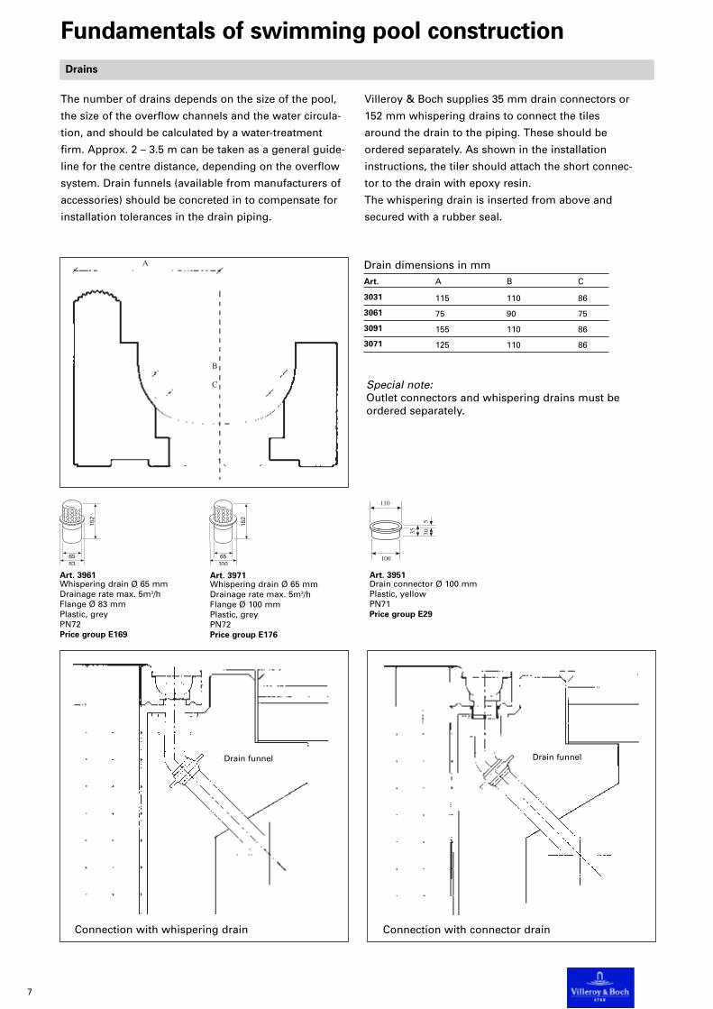
Drain funnel Drain funnel
Drains
Connection with connector drainConnection with whispering drain
Art. 3951Drain connector Ø 100 mmPlastic, yellowPN71Price group E29
Art. 3971Whispering drain Ø 65 mmDrainage rate max. 5m3/hFlange Ø 100 mmPlastic, greyPN72Price group E176
Art. 3961Whispering drain Ø 65 mmDrainage rate max. 5m3/hFlange Ø 83 mmPlastic, greyPN72Price group E169
The number of drains depends on the size of the pool,
the size of the overflow channels and the water circula-
tion, and should be calculated by a water-treatment
firm. Approx. 2 – 3.5 m can be taken as a general guide-
line for the centre distance, depending on the overflow
system. Drain funnels (available from manufacturers of
accessories) should be concreted in to compensate for
installation tolerances in the drain piping.
Villeroy & Boch supplies 35 mm drain connectors or
152 mm whispering drains to connect the tiles
around the drain to the piping. These should be
ordered separately. As shown in the installation
instructions, the tiler should attach the short connec-
tor to the drain with epoxy resin.
The whispering drain is inserted from above and
secured with a rubber seal.
Drain dimensions in mmArt. A B C
3031 115 110 86
3061 75 90 75
3091 155 110 86
3071 125 110 86
Special note:Outlet connectors and whispering drains must beordered separately.
Fundamentals of swimming pool construction

8
Thanks to its decades of experience,
Villeroy & Boch is the competent part-
ner for the construction of new and
restoration of existing swimming
pools. Our company offers you a
consultation and planning service
that will assist you in all stages of
project implementation. Please talk
to the Villeroy & Boch sales
representatives or to the relevant
department directly. See addresses
on pages 252, 340.
Swimming pool renovation
Art. 3070
Art. 3201
397
397
397
397
397
397
397
5150
225 473
473
473
4720
473
473
473
125
25 225 172
25
100
30
Art. 2706 "B"-0.02
±0.00inclined
Capillary breakingjoint fillerWater level
8,35 l/m25
25 300
Bonded waterproofing
30
Art. 3103
37 l/m
96 113
Art. 3002 Art. 2706 "B"
723
473
25
3250
3
25
347
347
347
2047
347
347
347
Art. 3201
Art. 3591 Art. 2706 "B"
Art. 3591
Art. 3171 orArt. 3215
±0.00inclined
4147
430
30
3197
3
6
25
Water level
397
397
397
397
397
397
3 15
Bonded waterproofing
Capillarybreakingjoint filler
25120
25180 208 170
20
25300
When renovating swimming baths,
it is often necessary to install a
composite seal directly under the
tile covering.

9
PRO ARCHITECTURA colours
System trim Article number Material PN00 PN04 PN13 page
Small overflow channel
Channel piece Art. 3070 Glazed / unglazed • • • 262
vitreous
Channel with drain Art. 3071 Glazed / unglazed • • • 262
vitreous
Inside corner Art. 3074 Glazed / unglazed • • • 262
vitreous
Overflow channelwith functional trims
Art. 3070, Art. 3090Uses (preferable):Indoor, outdoor, recreation,fun and hotel pools
Large overflow channel
Channel piece Art. 3090 Glazed / unglazed • • • 263
vitreous
Channel with drain Art. 3091 Glazed / unglazed • • • 263
vitreous
Inside corner Art. 3094 Glazed / unglazed • • • 263
vitreous
Accessories
Whispering drain Art. 3971 Plastic, grey 254, 262, 263, 269
Drain connector Art. 3951 Plastic, yellow 254, 262, 263, 269
Overview of pool edge systemsHigh water level

10
PRO ARCHITECTURA colours
System trim Article number Material PN00 PN04 PN13 page
“Finnish” overflow system
Grip ledge Art. 3002 Glazed vitreous • 264
Grip trough Art. 3003 Glazed vitreous • 264
Outside angle piece Art. 3005 Glazed vitreous • 264
Double bullnose
Rounded running piece Art. 3086 Glazed vitreous • • • 272
Pool ladder
Pool ladder Art. 3082 Glazed vitreous • • • 273
Rounded Art. 3486 Glazed vitreous • • • 272
running piece
Rounded Art. 3487 Glazed vitreous • • • 272
corner
Rounded Art. 3087 Glazed vitreous • • • 272
corner
Z-profile Art. 3591 Glazed vitreous • • 264
“St. Moritz” system
Small format tilesArt. 3002, Art. 3003Uses (preferable):Recreation, hotel andprivate pools
Overflow system with ceramicgrip ledge
Art. 3002, Art. 3005Uses (preferable):Indoor, outdoor, recreation,fun and hotel pools
Finnish “Pyrmont” system
Art. 3003, Art. 3591Uses (preferable):Outdoor, recreation,sport and teaching pools
High water level
Overview of pool edge systems

11
Accessories
Whispering drain Art. 3961 Plastic, grey 254, 268
Drain connector Art. 3951 Plastic, yellow 254, 262, 263, 269
Whispering drain Art. 3971 Plastic, grey 254, 262, 263, 269
Small pool edge piece
Running edge Art. 3065 Glazed / unglazed • • • 261
vitreous
Running edge, Art. 3069 Glazed / unglazed • • • 261
outside corner vitreous
Running edge, Art. 3468 Unglazed vitreous • 261
inside corner
“Wiesbaden” system
Art. 3060, Art. 3030,Art. 3065Uses (preferable):Indoor, outdoorand therapy pools
PRO ARCHITECTURA colours
System trim Article number Material PN00 PN04 PN13 PN70 page
Small “Wiesbaden” pool overflow
Channel piece Art. 3060 Glazed vitreous • • • 268
Channel with drain Art. 3061 Glazed vitreous • • • 268
Inside corner Art. 3064 Glazed vitreous • • • 268
Large “Wiesbaden” pool overflow
Channel piece Art. 3030 Glazed vitreous • • • 269
Channel with drain Art. 3031 Glazed vitreous • • • 269
Inside corner Art. 3034 Glazed vitreous • • • 269
Low water level
Overview of pool edge systems

12
Large “Wiesbaden” pool overflow
Accessories
Whispering drain Art. 3961 Plastic, grey 254, 268
Drain connector Art. 3951 Plastic, yellow 254, 262, 263, 269
Whispering drain Art. 3971 Plastic, grey 254, 262, 263, 269
PRO ARCHITECTURA colours
System trim Article number Material PN00 PN04 PN13 page
Small “Wiesbaden” pool overflow
Channel piece Art. 3060 Glazed vitreous • • • 268
Channel with drain Art. 3061 Glazed vitreous • • • 268
Inside corner Art. 3064 Glazed vitreous • • • 268
Channel piece Art. 3030 Glazed vitreous • • • 269
Channel with drain Art. 3031 Glazed vitreous • • • 269
Inside corner Art. 3034 Glazed vitreous • • • 269
“Therapy” system
Art. 3060, Art. 3030Uses (preferable):Therapy pools
Special solution – therapy pools | high-/low-level
Overview of pool edge systems

13
PRO ARCHITECTURA colours
System trim Article number Material PN00 PN04 PN13 PN70 page
Small pool edge piece
Running edge Art. 3065 Glazed / unglazed • • • 261
vitreous
Running edge, Art. 3069 Glazed / unglazed • • • 261
outside corner vitreous
Running edge, Art. 3468 Unglazed vitreous • 261
inside corner
“Skimmer” system
Art. 3065Uses (preferable):Private pools
Low water level
Overview of pool edge systems

14
Art. 3201
Art. 3065
Art.2200 "B"
±0.00
405
973
397
397
397
397
575
Water level
Skimmer according to manufacturer's instructions
Low water level | Small pool edge piece
Pool edge systems in detail
Art. 3065Channel piecePN00, PN04, PN13Price group E89
Art. 3468Inside cornerPN00, PN04, PN13Price group E113
This article is made of unglazed vitreousand is only available in the colour PN70,as only the unglazed bead is visible.
Art. 3069Outside cornerPN00, PN04, PN13Price group E144
ApplicationsMaterial
Actual sizeJoints approx.
SurfaceFinishGlaze
PackingCalculation unit
Special points
Matching wall tiles
Pool edge - indoors / outdoorsGlazed / unglazed vitreoussee diagrams5 mmformeduni-colouredmattPiecePiece
For reasons of slip resistance,the bead is unglazed.
PRO ARCHITECTURA
Low water level – ”Skimmer” system
Uses (preferable):Private pools
Note:
To ensure swimming pool water of hygienic quality, the water is to be treated and disinfected in accordance
with DIN 19643-1 (treatment of water for swimming pools). To prevent fungal attack, the surfacing is to undergo
thorough cleaning once annually, replacing the entire filling of water.

15
Art. 3070
Art. 3201
397
397
397
397
397
397
397
5150
225 473
473
473
4720
473
473
473
125
25 225 172
25
100
30
Art. 2706 "B"-0.02
±0.00inclined
Capillary breakingjoint fillerWater level
8,35 l/m
25 300
25
Watertight concrete
Bonded waterproofing
Reaction resin filler
Art. 3971Whispering drain Ø 65 mmDrainage rate max. 5m3/hFlange Ø 100 mmPlastic, greyPN72Price group E176
High water level – overflow channel with moulded trims
Uses (preferable):Indoor, outdoor, recreation, fun and hotel pools
Art. 3070Channel piecePN00, PN04, PN13Price group E94
Art. 3074Inside cornerPN00, PN04, PN13Price group E162
Art. 3071Outlet Ø 86 mmPN00, PN04, PN13Price group E119
Art. 3951Outlet Ø 100 mmPN00, PN04, PN13Price group E29
High water level | Small overflow channel – Wiesbaden pool overflow
ApplicationsMaterial
Actual sizeJoints approx.
SurfaceFinishGlaze
PackingCalculation unit
Special points
Matching wall tiles
Pool edge - indoors / outdoorsGlazed / unglazed vitreoussee diagrams5 mmformeduni-colouredmattPiecePiece
For reasons of slip resistance,the bead is unglazed.
PRO ARCHITECTURA
Pool edge systems in detail

16
140
210
300
40
35
105
35
15
60
10
300
155
Art. 3090
Art. 3201
Art. 3005 "C" Art. 2200 "B"
25 300
603003
9720
973
973
397
397
397
397
397
397
397
5200
25
135
30-0.035
±0.00
inclined
Capillary breakingjoint filler
25 300
Water level
19.0 l/m25
Watertight concrete
Bonded waterproofing
Reaction resin filler
Art. 3971Whispering drain Ø 65 mmDrainage rate max. 5m3/hFlange Ø 100 mmPlastic, greyPN72Price group E176
High water level – overflow channel with moulded trims
Uses (preferable):Indoor, outdoor, recreation, fun and hotel pools
Art. 3090Channel piecePN00, PN04, PN13Price group E112
Art. 3094Inside cornerPN00, PN04, PN13Price group E162
Art. 3091Outlet Ø 86 mmPN00, PN04, PN13Price group E131
Art. 3951Drain connector Ø 100 mmPlastic, yellowPN71Price group E29
High water level | Large overflow channel – Wiesbaden pool overflow
ApplicationsMaterial
Actual sizeJoints approx.
SurfaceFinishGlaze
PackingCalculation unit
Special points
Matching wall tiles
Pool edge - indoors / outdoorsGlazed / unglazed vitreoussee diagrams5 mmformeduni-colouredmattPiecePiece
For reasons of slip resistance,the bead is unglazed.
PRO ARCHITECTURA
Pool edge systems in detail

17
8,5
30
723
973
973
25
3250
3
25
347
347
347
3
14
347
347
347
347
Art. 3002
Art. 3103
37 l/m
170
397
397
397
397
397
397
3 159
25 300
Art. 3201
25 328 208
275
Art. 3591Art. 3246 "C" Art. 2706 "B"Art. 3591
Art. 3171 orArt. 3215
±0.00 inclined
inclination max 10%
4147
430
30
3197
3
6
25
96 113
Water level
Watertight concrete
Bonded waterproofing
Capillarybreakingjoint filler
Reaction resin filler
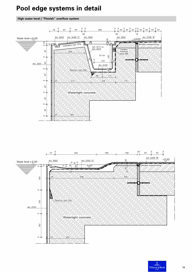
High water level | “Finnish” overflow system
Art. 3002Grip ledgePN04Price group E30
Art. 3003Grip troughPN04Price group E30
Art. 3591Running edgePN00, PN04Price group E23
Art. 3005Angle piecePN04, PN70Price group E30
ApplicationsMaterial
Actual sizeJoints approx.
SurfaceFinishGlaze
PackingCalculation unit
Matching wall tiles
Special points
Pool edge - indoors / outdoorsGlazed / unglazed vitreoussee diagrams3 mmformed, roughuni-colouredmattPiecePiece
PRO ARCHITECTURA
Underwater edges such as steps or the front edge of the“Finnish” system must be accentuated with a stripe ofa different colour (PA06).
In Germany, FINNISH overflow systems are expected tosatisfy the following requirements:• The pool edge must offer something to hold onto (grip).• The grip must be 15 mm high/deep.• The grip must be situated within 100 mm of the verticalwall of the pool.
• The rear side of the grip should be as verticalas possible.
• The top of the grip must be accentuated by means of astripe of contrasting colour measuring at least 2.5 cmacross.
• The slope of the washover incline must be about 10 %,and the surface finish must answer the description ofslip resistance category C.
Pool edge systems in detail
18
3197
3197
3197
3 15
15
30
20
723
352 166 18020
973
973
Art. 3002
25 300
30
50
Art. 3107
50
30Art. 2702 "C"
25 548 200
Art. 2200 "B"+0.02
-0.03±0.00Water level
Watertight concrete
Bonded waterproofing
Reaction resin filler
30
723
973
973
25
3250
3
25
347
347
347
3
14
347
347
347
347
Art. 3103
37 l/m
170
Art. 3201
258
25 314 208
Art. 3003
25 300
Art. 3591Art. 3246 "C" Art. 2706 "B"Art. 3591
Art. 3171 orArt. 3215
±0.00
inclination max 10%
inclined
4147
430
30
3197
3
6
25
96 113
Water level
Watertight concrete
Bonded waterproofing
Capillarybreakingjoint filler
Reaction resin filler
397
397
397
397
397
397
3 102
3
High water level | “Finnish” overflow system
Pool edge systems in detail

19
30
Art. 3103
37 l/m
96 113
Art. 3002 Art. 2706 "B"
25180 208 170
20
723
473
25
3250
3
25
347
347
347
2047
347
347
347
25300
Art. 3201
Art. 3591 Art. 2706 "B"
Art. 3591
Art. 3171 orArt. 3215
±0.00inclined
4147
430
30
3197
3
6
25
Water level
397
397
397
397
397
397
3 15
25120
Watertight concrete
Bonded waterproofing
Capillarybreakingjoint filler
Reaction resinfiller
235
30
30
Art. 3103
37 l/m
96 113
723
603
2503
603
9720
973
97
25 163 208 15520
Art. 3002
25 300
Art. 3201
Art. 2200 "B"Art. 3005 "C" Art. 3005 "C"
Art. 3171 orArt. 3215
±0.00inclined
4147
430
30
3197
3
6
25
Water level
30
15
397
397
397
397
397
397
3 15
25 103
Watertight concrete
Bonded waterproofing
Capillary-breakingjoint filler
Reaction resinfiller
Pool edge systems in detail
Uses (preferable): Indoor, outdoor, recreation, fun and hotel pools
Uses (preferable): Indoor, outdoor, recreation, fun and hotel pools
High water level | Overflow system “Finnish”

20
Uses (preferable): Recreation, hotel and private pools
High water level | St. Moritz System
Pool edge systems in detail
• The rounded-off pool border is
higher than the pool surround.
• The water level is approximately
50-60 cm above the pool surround.
• The water flows over the pool
border, running down the
outside and into the overflow
channel, the top of which is flush
with the pool surround. The over-
flow is executed either as a shal-
low, open trough or as
a grate-covered, tiled, channel.
• Small format tiles are preferable.
• With deference to possible
erosion, epoxy resin should be
used for filling the
joints.
Art. 3753
Art. 3103
Art. 3215
Art. 3215
Art. 3002
Art. 3591 Art. 3215Art. 2200 "B"
23
2
23
3
72
197
3197
3197
3197
3197
3
15
25
25
170 25
303
147 70 29025
30
115
25
600
-0.60
±0.00
inclined
Water level
Watertight concrete
Bonded waterproofing
Capillarybreakingjoint filler
Reaction resin filler

21
5,2 l/m
25
100
25
25 300
405
973
973
9720
973
973
342
Art. 3107
Art. 2200 "B"
Art. 3107
Art. 3060
Art. 3065
Art. 3709±0.00
3197
3197
5100
548
89
75
25 12025
172
Water level
Bonded waterproofing
Watertight concrete
Capillary breakingjoint filler
Reaction resin filler
Low water level | Small “Wiesbaden” pool overflow
Art. 3060Channel piecePN00, PN04, PN13Price group E82
Art. 3064Inside cornerPN00, PN04, PN13Price group E123
Art. 3061Outlet Ø 86 mmPN00, PN04, PN13Price group E118
Art. 3961Whispering drain Ø 65 mmDrainage rate max. 5m3/hFlange Ø 83 mmPlastic, greyPN72Price group E169
Low water level
Uses (preferable):Indoor, outdoor and therapy pools
Pool edge systems in detail
ApplicationsMaterial
Actual sizeJoints approx.
SurfaceFinishGlaze
PackingCalculation unit
Matching wall tiles
Pool edge - indoors / outdoorsGlazed vitreoussee diagrams5 mmformeduni-colouredmattPiecePiece
PRO ARCHITECTURA

22
25 225 242
25 300
232
235
3197
3197
5150
160
75
25
150
25
491
Art. 3065 Art. 2215 "B"
Art. 3107
Art. 3030
±0.00
Art. 3107
20025
405
1464
1464
14620
1464
Water level
14.5 l/m
Watertight concrete
Bonded waterproofing
Capillary breakingjoint filler
Reaction resin filler
Low water level
Uses (preferable):Indoor, outdoor and therapy pools
Art. 3030Channel piecePN00, PN04, PN13Price group E91
Art. 3034Inside cornerPN00, PN04, PN13Price group E137
Art. 3031Outlet Ø 86 mmPN00, PN04, PN13Price group E121
Art. 3951Drain connector Ø 100 mmPlastic, yellowPN71Price group E29
Art. 3971Whispering drain Ø 65 mmDrainage rate max. 5m3/hFlange Ø 100 mmPlastic, greyPN72Price group E176
Low water level | Large “Wiesbaden” pool overflow
Pool edge systems in detail
ApplicationsMaterial
Actual sizeJoints approx.
SurfaceFinishGlaze
PackingCalculation unit
Matching wall tiles
Pool edge - indoors / outdoorsGlazed vitreoussee diagrams5 mmformeduni-colouredmattPiecePiece
PRO ARCHITECTURA

23
5,2 l/m
14525
25
100
Art. 3086
350
25120
25205
25
25 300
Art. 3201
640
Art. 3201
15 10
42
560
597
397
397
397
397
397
560
Art. 3709
123 605
482
482
484
60
Art. 3350 (cut)
397
397
397
397
397
397
397
397
5100
548
560
218
25
Art. 3060
Art.3086
+0.12
-0.68
1
2
3
±0.00Water level 75
Art. 2072 "B" Art. 2200 "B"
1 2 3
Watertight concrete
Polystyrene strip
=Elastic joint sealant
Capillarybreakingjoint filler
Reaction resin filler
• The pool must have an overflow channel on at
least one side and one end.
• As a rule, the therapist’s gallery should run along
one side of the pool and have a minimum width
of 75 cm and a minimum depth of 80 cm.
• A handrail or ledge must be provided at the edge
of the pool (water level).
• The steps must be at least 60 cm wide.
• The maximum slope for ramps is 15 %.
In Germany, the design and construction of medi-
cinal baths is subject to the following basic rules:
• The minimum dimensions for therapy pools are
3 x 4 m.
• The minimum water depth is 0.5 m for children
and 0.8 m for adults.
• The maximum water depth is 1.35 m.
• The pool must have an overflow channel running
along all its sides. Skimmers are not acceptable for
hygienic reasons.
• The slope of the pool’s floor should ideally be
constant, and should not exceed 4%.
Special designsTherapy pools

24
5,2 l/m
75
250
75
Art. 3201150
100
25
25
100
759075
2535025
20525
145
397
397
397
397
397
397
397
397
5100
5145
5123
25
3147
3147
287113
Art. 3753
Art. 3060
1
3
4
2
+0.15
-0.75
±0.00Water level
1 2 3 4
Art. 2404 "B"
Watertight concrete
Bonded waterproofing
Capillarybreakingjoint filler
= Elastic joint sealant
Reaction resin filler
Special designsTherapy pools

25
25
110
55
885
25
300 185
485
425 66 88 30
25
25
605
485
300 603
473
473
4720
473
473
473
473
473
25
Art. 3709
Art. 3709
Art. 3090
Art. 3709
155
Art. 3486
Art. 3086
25
109
Art. 3005 Art. 2706 "B"
-0.522
-0.035
±0.00
inclined
Water level
560
10
Watertight concrete
Bonded waterproofing
Top concrete layer
Capillarybreakingjoint filler
Reaction resin filler
Large double bullnose
Small double bullnose
Moulded trims
ApplicationsMaterial
Actual sizeJoints approx.
SurfaceFinishGlaze
PackingCalculation unit
Matching wall tiles
Pool edge - indoors / outdoorsGlazed vitreoussee diagrams5 mmformeduni-colouredmattPiecePiece
PRO ARCHITECTURAArt. 3086Rounded running piecePN00, PN04, PN13Price group E20
Art. 3087Rounded cornerPN00, PN04, PN13Price group E43
Art. 3486Rounded running piecePN00, PN04, PN13Price group E18
Art. 3487Rounded cornerPN00, PN04, PN13Price group E33
ApplicationsMaterial
Actual sizeJoints approx.
SurfaceFinishGlaze
PackingCalculation unit
Matching wall tiles
Pool edge - indoors / outdoorsGlazed vitreoussee diagrams5 mmformeduni-colouredmattPiecePiece
PRO ARCHITECTURA

26
37 l/m
72 3 97 3 97 3 60 3 250 3 47 3 47 3 47 3 47 3
14
3 47 3 47 3 47 3
80 2 80 19
6
3
97 3 44 3 25
156 25
30
311
Art. 3002
100 156 25
Art. 3201
Art. 3082
Art. 3201
Art. 3103
102 108
Art. 3246 "C" Art. 2706 "B"Art. 3005 "C" Art. 3215
Art. 3171 orArt. 3215
±0.00 inclined
inclination max 10%
Water level
306
306
306
300
15
397
397
397
397
397
397
397
397
397
397
397
397
3 151
5
Bonded waterproofing
Watertight concrete
Capillary breakingjoint filler
Reaction resin filler
Moulded trimsLadder
Art. 3082Ladder
ApplicationsMaterial
Actual sizeJoints approx.
SurfaceFinishGlaze
PackingCalculation unit
PN00, PN04, PN13
Matching wall tiles
Pool edge - indoors / outdoorsGlazed vitreoussee diagrams5 mmformeduni-colouredmattPiecePiecePrice group E86
PRO ARCHITECTURA

27
8,5
Art. 3005Angle piecePN04, PN70Price group E30
Art. 3003Grip troughPN04Price group E30
Pool access steps
Moulded trims
Pool edge - indoors / outdoorsGlazed / unglazed vitreoussee diagrams3 mmformed, roughuni-colouredmattPiecePiece
PRO ARCHITECTURA
Underwater edges such as steps or the front edge of the“Finnish” system must be accentuated with a stripe ofa different colour (PA06).
ApplicationsMaterial
Actual sizeJoints approx.
SurfaceFinishGlaze
PackingCalculation unit
Matching wall tiles
Special points
30
603
973
973
343
25
603
973
973
343
300
158
4147
4303
63
121
30
329
397
3 25
30
329
397
3 25
603
973
973
37
30
Art. 3103
37 l/m
300 300 30025
250
213 208 200
Art. 3201
62 973
24
3250
3297
3
Art. 3003
30
3197
3
6
25
-0.48
-0.32
-0.16
Art. 3246 "C"
Art. 3591
Art. 3246 "C"Art. 2122 "B"
Art. 3005 "C"
±0.00 inclined
Art. 3171 orArt. 3215
Art. 2121 "B" or
96 112
Water level
Top concrete layer Watertight concrete
Bonded waterproofing
Capillarybreakingjoint filler
inclinationmax 10%
Reaction resin filler

28
Surround formed as single span slab Surround formed as cantilever slab on the pool
Surround formed as cantilever slab on thestructure
> 150±0.00inclined
Water level
TilesThin-bed mortar
Watertight concrete
Sloping screed covered with thermal insulation,protective sheet and reinforced screed
Sealing tape
Bonded waterproofing
Capillary breaking joint filler
Elastic joint sealant with closed cell rope
Reaction resin filler
The movement joint is situated in an area which is
exposed to high strain through water. The type of
water-proofing to be used for the joint depends on
the waterproofing of the pool surround.
Nowadays, pool surrounds are usually water-
proofed with brushable coatings, so-called alternati-
ve waterproofing, in accordance with ZDB leaflet.
Waterproofing of movement joints for overflow systems
Technical aspects of application for swimming poolsStatic systems, movement joints
The pool must be structurally independent of the
remaining structure. The structural engineer is
responsible for selecting the static system. His
decision dictates the arrangement of movement
joints around and, where necessary, within the pool.
The following static systems can be used to effect
the structural separation of the pool from the
remaining structure.

29
Tiles
Stop end joint tapeElastic joint sealant
Reinforcement
Pools made of watertight concrete
The pool is made of impermeable concrete in accor-
dance with DIN 1045 and the structural analysis.
The concrete must be and remain free of cracks.
The following points should be heeded when
building the pool:
• Proper composition of aggregates and according-
ly a low water/cement ratio.
• For practical reasons, pool floors and walls should
be at least 25 cm thick and the upturn behind
and/or in front of the drainage channel should be
at least 15 cm thick, in the absence of any addi-
tional sealing.
• Optimal compaction of freshly poured concrete by
means of an immersion vibrator.
• Appropriate aftertreatment of concrete
(by keeping it moist)
• Minimum strength category of concrete: B25.
• Minimum overlap of reinforcing rods: 5 cm.
• For pools intended to be filled with aggressive
water, e.g. salt water, the bonding agents used
should be selected on the basis of a water
analysis.
• It is desirable to pour the floor and walls in a
single operation. Should a construction joint
between the floor and the walls be necessary,
a stop-end joint tape must be inserted.
Technical aspects of application for swimming poolsPool construction
Pools to be clad with tiles are usually made of reinfor-
ced concrete.
In some cases pools made of steel - e.g. on pleasure
cruisers - or plastic can also be lined with vitreous
tiles. In such cases, please ask for more detailed infor-
mation.
The following considerations apply exclusively to
reinforced waterlight concrete pools.
This can be achieved by:
• using impermeable concrete or
• waterproofing.
After completing the reinforced concrete body of the
pool, in order to verify watertightness, the customer is
to fill the pool with chlorinated water for test purpos-
es to the level of the rim around the pool (exposed
concrete). The outside of freestanding pools should
also not be waterproofed until after the leak test.
Marking the water level during the leak test provides
an excellently accurate line of reference for positio-
ning the ceramic accessories for the overflow without
the need for carrying out special additional measure-
ments.

30
Levelling coatTilesThin-bed mortarBonded waterproofing
Insulation strip
Sealing tape in cornerElastic joint sealantClosed cell rope
Screed
Watertight concrete
TilesThin-bed mortarBonded waterproofingSealing tape
Elastic joint sealantClosed cell rope
Screed
Watertight concrete
Waterproofing on structure joint Waterproofing at wall/floor joint
Waterproofing
Pipes are incorporated in the surface waterproofing
by means of a gasket or flange.
Floor drains need a wide flange to take the water-
proofing.
Waterproofing should be carried out according to
the manufacturers instructions. The thickness of the
waterproofing depends on the material used and
the specifications of the manufacturer.
At structure joints and corners wherever move-
ments are to be expected, the waterproofing should
be reinforced with bonded fabric or foil.
Suitable bases
• Concrete in accordance with DIN 1405
and DIN 4227
• Underlay waterproof plaster in accordance with
DIN 18550, mortar group P III
• Levelling screed as bonded levelling screed in
accordance with DIN 18560, quality ZE 20
The dimensional accuracy of the backing should
correspond with the finished cladding. Considerable
unevenness should be compensated for beforehand
with underlay waterproof plaster or levelling screed.
The base material must be free of abherents, debris,
dust, binding agents, efflorescence or other conta-
minants that could impair adhesion.
Concrete surfaces on the pool walls should be sand-
blasted.
Resulting cracks or the movement of existing cracks
should not exceed 0.5 mm. Cracks of more than
0.5 mm width must be grouted under pressure.
As a technical rule for this type of waterproofing see
the leaflet from the ZDB “Ceramic tiles in swimming
pool construction - Advice on planning and imple-
mentation.” and DIN 18195-7.
Materials to be used:
• Synthetic cement mixtures or
• Reactive resins
Required properties:
• Adhesive strength ≥ 0.5 N/mm2
• Frost resistance ≥ 0.5 N/mm2
• Thermal stability 70°C (HZF) ≥ 0,5 N/mm• Resistance to caustic potash solution 3% ≥ 0,5 N/mm• Resistance to lime water ≥ 0,5 N/mm
2
• Resistance to lime water ≥ 0.5 N/mm2
• Impermeability to water after 7 days at 3 bar
• Bridging cracks of up to 0.4 mm
(Fix load over 24 hours)
• Resistance to chemicals
Pools with waterproofing bonded with ceramic tiles
Technical aspects of application for swimming poolsPool construction

31
Concrete
(acc.w. DIN 18195)
Reinforced screed(burden-sharing course)
Thin-bed mortar
Tiles
(single layer)Separation layer
(acc. DIN 18157)
Bonded waterproofingConcrete
Reinforced screed
Thin-bed mortar
Tiles
(double layer)Separation layer
(acc. DIN 18157)
(local distribut. course)
Concrete
Thermal insulation
(double layer)
Reinforced screed
Thin-bed mortar
Tiles
Separation layer
(acc. DIN 18157)
(local distribut. course)
Concrete
(Levelling course)
Tiles
Concrete
Thin-bed mortar
Tiles
Concrete
Thick-bed mortar(Levelling course)
Tiles
Thin-bed mortar
Bonding course
Bonding course
(acc. DIN 18157) (acc. DIN 18157)
Bonded screed
Floating claddings
Floating claddings
Unlike bonded claddings, floating claddings should
be subdivided by movement joints around the bor-
ders of and between individual sections.
A floating cladding is when the cladding is separated
from the backing by insulation, foils, oil-impregnated
paper or the like in accordance with DIN 18195.
Technical aspects of application for swimming poolsCeramic claddings
Bonded claddings
Bonded claddings
Bonded claddings are based on the principle of
frictional connection, i.e. no movement is possible
between the ceramic tiles and the solid base, much
like in a reinforced concrete component.
The conventional setting method involves the use of
bedding mortar, while the thin bed method in accor-
dance with DIN 18157 relies on an adhesive to effect
the bond. To achieve a good bond, the base material
must be free of the following:
• residue and debris such as wood, metal, formwork
lube or other contaminating layers that could
impair adhesion
• cracks or efflorescence
• considerable unevenness
• too smooth a surface.
Movement joints should be limited to the same locati-
ons and widths as those of the existing structure
In principle all types of tiling belong to one of the
following groups:
• Bonded claddings
• Floating claddings
Differentiation is necessary with deference to:
• The properties of the finished cladding
• The anticipated stress levels in the cladding
construction
• The size of sections and the location and
execution of expansion/structural joints.

32
Note:
To ensure swimming pool water of hygienic quality, the water is to be treated and disinfected in accordance
with DIN 19643-1 (treatment of water for swimming pools). To prevent fungal attack, the surfacing is to undergo
thorough cleaning once annually, replacing the entire filling of water.
Pool claddings
In the case of a swimming pool made of imperme-
able concrete the tiles are attached by means of the
BONDED CLADDING principle.
VOB-DIN 18352 “Working with tiles and slabs”
applies for bonded cladding in mortar (so-called
conventional or thick bed tiling)
DIN 18157 “Tiling ceramic coverings using the thin
bed method” applies for thin bed tiling.
DIN 18550 “Plaster” applies for screeds, DIN 18560 –
Part 3 “The use of screeds – bonded screeds”.
If the backing is as level as the finished cladding is
expected to be, the tiles can be fixed directly to the
concrete by the thin bed method.
In general, however, it is necessary to compensate for
a certain amount of unevenness. This is done by
applying an underlay of waterproof plaster of mortar
group III, preferably pure cement plaster. The tiles are
attached to the prepared backing with a thin bed of
hydraulic mortar in accordance with DIN 18156, Part 2.
When fixing the tiles directly on to the shotcrete with
a cement-based mortar, the back of the vitreous tiles
must first be powdered lightly with cement or coated
with cement-based grout.
Most serious damage resulting from the failure of the
bond between the tiles and the backing is caused by
shear stresses building up in the interface. Shear
stress occurs most often when the “young” concrete
is tiled before it has finished shrinking.
In accordance with point 7.2 of the information leaflet
"Schwimmbadbau" - Hinweise für Planung und
Ausführung Keramischer Beläge im
Schwimmbadbau" ("Swimming pool construction –
Instructions on planning and producing ceramic
coverings in swimming pool construction"), publis-
hed by the central association of the German buil-
ding industry (ZDB) in July 2008, the concrete should
have a minimum age of 6 months pursuant to DIN
1045.
Technical aspects of application for swimming poolsCeramic claddings

33
Dry area Wet area
Angle beads with
Bonded waterproofing
Doo
rle
af
movement joints
Sealing tape
inclined
Closed cell rope
Screed
Bonded waterproofing
Thin-bed mortar
Tiles
Glass fibre fabric collar
Reinforcing collar
Polymer concrete collar
inclined inclined
TilesThin-bed mortarBonded waterproofing
Edge protection beadSealing tape
Elastic joint sealerClosed cell rope
Screed
Watertight concrete
Bonded waterproofing
Figure 3: Transition between a wet and a dry room
Figure 2: Waterproofing connection at drain
Floor and wall claddings in wet rooms
Figure 1: Waterproofing on screed joint
Floor claddings which are classified as having a
high exposure to moisture require waterproofing
and that the floors slope towards the drains. Ths
slope of the waterproofing layer corresponds to that
of the finished tiling. For ceramic tiles a slope of 1 –
2 % is usually sufficient. In showering rooms the
floor in the vicinity of the showers should slope at
a 3% gradient.
The waterproofing must extend over movement
joints. Permalastic sealing strips should be used for
this purpose. (Figure 1)
Drains are to be integrated into the surface water-
proofing by means of a flange or gasket. (Figure 2)
The level of the floor at the transition between wet
and dry rooms can be the same. The transition
should, however, not lie within the splash area and
the rooms should be separated by a door. The floor
of the wet room should slope sufficiently towards
the drain. (Figure 3)
Pipes and tap fittings that penetrate wall claddings
are integrated into the surface waterproofing by
means of a press-on flange.
Technical aspects of application for swimming poolsCeramic claddings

34
Heating conductor
Bonded waterproofingSealing tape
Elastic joint sealantClosed cell rope
Pipe sleeve
Movement in heated and unheated floating coverings Movement joint in heated claddings.
Ceramic tiles on underfloor heating
Technical aspects of application for swimming poolsCeramic claddings
Screeds on an insulating layer and heated screeds
should be reinforced. These screeds are to be divid-
ed into sections by section boundary joints: in
unheated screeds maximum 60 m2 in size with a
maximum edge length of 8 m and in heated screeds
maximum 40 m2 in size with a maximum edge
length of 6.5 m. Compact sections should be creat-
ed wherever possible. Structural joints should be
taken on in the same width and in the same location.
The screed sections should also be subdivided at
doorways and wall projections. The heating pipes
should not cross the section joints in heated screeds
where possible. If this should prove necessary,
300 mm long pipe sleeves should be used.