swelling kinetics of a microgel shell - harvard university...monodisperse polymer gel shells by...
TRANSCRIPT

pubs.acs.org/MacromoleculesPublished on Web 11/05/2009r 2009 American Chemical Society
Macromolecules 2009, 42, 9357–9365 9357
DOI: 10.1021/ma901362p
Swelling Kinetics of a Microgel Shell
Joshua Wahrmund,† Jin-Woong Kim,‡,§ Liang-Yin Chu,‡, ) Changjie Wang,^ Yong Li,#
Alberto Fernandez-Nieves,‡,3 David A. Weitz,*,‡ Arkadii Krokhin,*,† and Zhibing Hu*,†
†Department of Physics, University of North Texas, Denton, Texas 76203, ‡School of Engineering and AppliedSciences, Department of Physics, Harvard University, Cambridge, Massachusetts 02138, §Amore-PacificR&D Center, 314-1, Bora-dong, Giheung-gu, Yongin-si, Gyeonggi-Do, 446-729 Korea, )School of ChemicalEngineering, Sichuan University, Chengdu, Sichuan 610065, China, ^Haynes and Boone, LLP, Richardson,Texas 75082, #Kimberly-Clark Corporation, Neenah, Wisconsin 54957, and 3School of Physics,Georgia Institute of Technology, Atlanta, Georgia 30332
Received June 25, 2009; Revised Manuscript Received September 17, 2009
ABSTRACT: Tanaka’s approach to swelling kinetics of a solid gel sphere is extended to a sphericalmicrogelshell. The boundary condition at the inner surface is obtained from the minimization of shear elastic energy.Temporal evolution of a shell is represented in a form of expansion over eigenfunctions of the correspondingdiffusion equation. The swelling of Tanaka’s solid spherical gel is recovered as a special case of our generalsolution if the inner radius approaches zero. In another limiting case of a thin (balloon-like) shell, the set ofeigenfunctions is reduced to a single exponential term. In the general case, a solid sphere swells slightly fasterthan the same sphere with an internal cavity. To test our theoretical model, we prepared monodisperse poly-N-isopropylacrylamide (PNIPAM) hydrogel shells using a microfluidic device. The temporal dependence ofthe inner and outer radii of the shell were measured, and the data were fitted to our theoretical model. As aresult, we obtained the collective diffusion constants for shrinking and for swelling processes. The obtainedvalues for microgel shells are in excellent agreement with the previous results obtained for submillimeterPNIPAM solid spheres in the same temperature interval. Our model shows that the characteristic swellingtime of a gel shell should be proportional to the square of the outer radius not to the thickness of the shell,agreeing with experimental observation.
1. Introduction
Polymer gels have been studied extensively because of theirability to simulate biological tissues and to swell or collapsereversibly in response to external stimuli.1-8 Swelling of polymergels is one of the classical problems in both macromolecularscience and technology.9-12 Flory and Rehner developed anequilibrium swelling theory by considering the balance betweenthemixing of polymer chains with solvent and the elasticity of thepolymer chains.9 Ritger and Peppas presented mathematicalmodels for drugdiffusion fromhydrogels.10Tanaka andFillmorehave studied the swelling kinetics of spherical gels11 by using anequation of motion of the gel network.12
The study of swelling kinetics has been further extendedto different geometries: long solid gel cylinders and thin soliddisks.13-15 In these cases, a theoretical analysis of the kinetics ofgel swelling and solvent motion is based on the solution ofcoupled equations of motion for a network and solvent.16
Urayama et al. studied the kinetics of shrinking for polymer gelsinduced by ultracentrifugal fields.17 The swelling dynamics of along solid cylindrical gel were analyzed by the stress diffusioncoupling model, where the swelling is caused by an elongationforce applied to the gel.18 A continuum mechanical model wasproposed for dynamical processes in swelling gels, in whichsolvent permeation causes deformation.19 Furthermore, a modelfor transient deformation of neutral hydrogels that accounts forconservation of momentum, energy, and mass for the solidpolymer and fluid phase was derived.20
Most of these previous theoretical studies have focused on theswelling kinetics for solid gel structures, that is, structureswithoutinternal cavities. The theory of gel shells is still missing. At thesame time, experimental work on hollow polymer gels is makingrapid progress. For example, a positively thermosensitive drug-release microcapsule was designed, and its preparation wascarried out by the use of an air suspension coating techniquefor controlled drug release.21Mammalian cells were encapsulatedin cylindrical hydrogel microstructures or in cubic hydrogelstructures in microfluidic channels.22 Submicrometer hydrogelcages have been prepared as drug carriers.23 Hollow capsulescomposed of microgel particles have been synthesized with themicrogel particles assembling on the surfaces of water dropletsin oil.24
What actually motivates this work is the current synthesis ofmonodisperse polymer gel shells by microfluidic devices.25,26
These gel shells have radii of !60 !m and have characteristicswelling times that range around several tens of seconds. Thekinetics of these shells is easily measurable, but there is a lack oftheoretical description. The study of the swelling kinetics of gelswith shell structure will not only enhance our deep-seated under-standing of swelling kinetics for polymer networks but may alsoaid in the development of applications ranging from controlleddrug release to cell encapsulations.
Here we propose a theoretical model of swelling kinetics for apolymer gel shell.
This work is an extension of Tanaka’s work on a solid gel to ashell gel. Just as with Tanaka’s formulation for a solid gel, ourmodel for a gel shell is based on the motion of the gel network. Ineach case, the motion of the gel network is determined byconsidering the mechanical stress within the gel network. The
*Corresponding authors. [email protected] (Z.H.); [email protected](A.K.); [email protected] (D.A.W.).
9358 Macromolecules, Vol. 42, No. 23, 2009 Wahrmund et al.
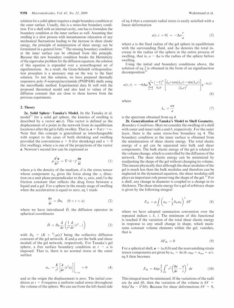
solution for a solid sphere requires a single boundary condition atthe outer surface. Usually, this is a stress-free boundary condi-tion. For a shell with an internal cavity, one has to formulate theboundary condition at the inner surface as well. Assuming thatswelling is a slow process with instantaneous relaxation of anymechanical fluctuations leading to the increase in shear elasticenergy, the principle of minimization of shear energy can beformulated in a general form.15 The missing boundary conditionat the inner surface can be obtained from this principle.Because this new boundary condition breaks the Hermiticityof the eigenvalue problem for the diffusion equation, the solutionof this equation is expanded over a nonorthogonal set ofeigenfunctions. As a result, the Gram-Schmidt orthogonaliza-tion procedure is a necessary step on the way to the finalsolution. To test this solution, we have prepared thermallyresponsive poly-N-isopropylacrylamide (PNIPAM) shells usingthe microfluidic method. Experimental data fit well with theproposed theoretical model and also lead to values of thediffusion constant that are close to those known from theprevious experiments.
2. Theory
2a. Solid Sphere-Tanaka’s Model. In the Tanaka et al.model11 for a solid gel sphere, the kinetics of swelling isdescribed by a vector u(r,t). This vector is defined as thedisplacement of a point in the network from its equilibriumlocation r after the gel is fully swollen. That is, u=0at tf¥.Note that this concept is generalized as interchangeablewith respect to the cases of both shrinking and swellingprovided the conventions u > 0 (for shrinking) and u < 0(for swelling), where u is one of the projections of the vectoru. Newton’s second law can be expressed as
FD2uDt2
! r 3 ~" -fDuDt
"1#
where F is the density of the medium, "~ is the stress tensorwhose component "ik gives the force along the xi direc-tion on a unit plane perpendicular to the xk axis, and f is thefriction constant that reflects the drag force between aliquid and a gel. For a sphere in the steady stage of swellingwhen the acceleration is equal to zero, eq 1 reads
DuDt
! D̂u, "0 < r < a# "2#
where we have introduced D̂, the diffusion operator inspherical coordinates
D̂ ! D0d
dr
1
r2d
dr"r2:::#
! ""3#
with D0 = (K $ 4/3!)/f being the collective diffusionconstant of the gel network. K and ! are the bulk and shearmoduli of the gel network, respectively. For Tanaka’s gelsphere, a free surface boundary condition at r = a isimposed. That is, there is no normal stress at the outersurface
"rr ! K
r2DDr
"r2u## $%%%%%
r!a
! 0 "4#
and at the origin the displacement is zero. The initial con-dition at t = 0 requires a uniform radial stress throughoutthe volume of the sphere. We can see from the left-hand side
of eq 4 that a constant radial stress is easily satisfied with alinear deformation
u"r, t ! 0# ! -!ar
a"5#
where a is the final radius of the gel sphere in equilibriumwith the surrounding fluid, and !a denotes the total in-crease in the radius of the sphere in the entire process ofswelling, that is, a - !a is the radius of the sphere beforeswelling.
Using the initial and boundary conditions above, thesolution of eq 2 is obtained in the form of an eigenfunctiondecomposition11
u"r, t# ! -6!aX¥
n!1
"-1#n
#na#nr cos"#nr#-sin"#nr#
"#nr#2
" #e-D0#
2nt
"6#
where
#n ! n$a
"7#
is the spectrum obtained from eq 4.2b. Generalization of Tanaka’s Model to Shell Geometry.
Boundary Conditions.Herewe consider the swelling of a shellwith outer and inner radii a and b, respectively. For the outerlayer, there is the same stress-free boundary eq 4. Theboundary condition at the inner surface is obtained fromthe minimization of shear elastic energy. The total elasticenergy of a gel can be separated into bulk and shearcomponents. The bulk elastic energy of the gel is related tothe volume change, which is controlled by the diffusion of thenetwork. The shear elastic energy can be minimized byreadjusting the shape of the gel without changing its volume.Thismeans physically that although the shearmodulus of thegel is much less than the bulk modulus and therefore can beneglected in the dynamical equation, the shear modulus stillplays an important role preserving the shape of the gel.15 Fora shell, any change in diameter is coupled to a change in itsthickness. The shear elastic energy for a gel of arbitrary shapeis given by the following integral
Fsh ! !Z
vuik -
1
3%ikull
! "2
dV "8#
where we have adopted summation convention over therepeated indices i, k, l. The minimum of this functionalis reached if the variation of the total shear elastic energyin response to any small change in shape, which main-tains constant volume elements within the gel, vanishes,that is
%Fsh ! 0 "9#
For a spherical shell, u=(u,0,0) and the nonvanishing straintensor components are given by urr= !u/!r, u&&= ujj= u/r.eq 8 then becomes
Fsh ! 4$!2
3
Z a
br2
DuDr
-u
r
! "2
dr "10#
This integral must beminimized. If the variations of the radiiare %a and %b, then the variation of the volume is %V =4$(a2%a - b2%b). Because for shear deformations %V = 0,

Article Macromolecules, Vol. 42, No. 23, 2009 9359
we have the following from combining eqs 9 and 10
%Fsh ! 8
3$!
Z a$ %a
b$ %br2
DuDr
-u
r
! "2
dr-Z a
br2
DuDr
-u
r
! "2
dr
" #
! 8
3$!
DuDr
-u
r
! "2%%%%%
%%%%%r!a
-DuDr
-u
r
! "2%%%%%r!b
2
4
3
5a2 %a ! 0
"11#
Because%a is an independent variation, the following bound-ary condition must be imposed
u"b, t#b
-Du"r, t#
Dr
%%%%%r!b
! u"a, t#a
-Du"r, t#
Dr
%%%%%r!a
"12#
The solution of the diffusion eq 2 with the boundary condi-tions eqs 4 and 12 and the initial condition eq 5 defines thekinetics of swelling.
Solution of Diffusion Equation.A solution of the diffusioneq 2 satisfying the boundary condition eq 4 is written as asuperposition of eigenfunctions
u"r, t# !X¥
n!1
AnZn"r#e-#2nD0t "13#
Zn"r# ! cos%#n"r-a#&#nr
-sin%#n"r-a#&
"#nr#2"14#
From the boundary condition at the inner surface (eq 12), weobtain
Zn"b#b
-Z0
n"b# ! Zn"a#a
-Z0
n"a# "15#
This relation gives the equation for the spectrum of theeigenvalues #n
3 cos%#n"a-b#&-"b2#2n -3# sin%#n"a-b#&#nb
! 3b2
a2"16#
The unknown coefficients An are calculated using the initialcondition eq 5. For t = 0, we have from eqs 13 and 5
!aa
r !X¥
n!1
AnZn"r# "17#
The coefficients An cannot be directly calculated from thisexpansion because the eigenfunctions Zn(r) are not orthogo-nal. This comes from the fact that the boundary condition atr = b breaks the Hermiticity of the diffusion operator
D̂ ! D0d
dr
1
r2d
dr"r2:::#
! ""18#
It is easy to show that theHermiticity condition Æu,D̂væ= Æv,D̂uæis not satisfied because of the nonzero boundary condition eq 12
Æu, D̂'æ ! Æ', D̂uæ$D0'"b#d
dr"r2u#
%%%%%r!b
-D0u"b#d
dr"r2'#
%%%%%r!b
"19#
Although the eigenfunctions Zn(r) of the non-Hermitian eigen-value problem are not orthogonal
ÆZn,Zmæ !Z a
br2Zn"r#Zm"r# dr
! sin%#n"a-b#& sin%#m"a-b#&b#2m#
2n
$ 1
#m#n"#2m -#2n#f#m sin%#m"a-b#& cos%#n"a-b#&
-#n sin%#n"a-b#& cos%#m"a-b#&g 6! 0 "20#
theyare linearly independentbecause thecorrespondingWrons-kian does not vanish
W"Zn"r#,Zm"r## !
%%%%%Z
0
n"r#,Z0
m"r#Zn"r#,Zm"r#
%%%%% ! ZmZ0
n -ZnZ0
m
! 1
r21
#ncos%#n"r-a#& sin%#m"r-a#&
&
-1
#mcos%#m"r-a# sin%#n"r-a#&
'6! 0: "21#
Therefore, the functionsZn(r) form a nonorthogonal basis, andthe orthogonalization procedure is the necessary step.
Gram-Schmidt Orthogonalization Procedure. We applythe Gram-Schmidt orthogonalization procedure to form anorthonormal basis.27 The ith vector of the orthonormal basisis calculated as follows
ni"r# ! RifZi"r#-Xi-1
j!1
ÆZijnjænjg "22#
ÆZijnjæ 'Z a
bZinjr
2 dr "23#
Here the coefficients Ri are calculated from the normal-ization condition
Z a
bn2i "r#r
2 dr ! R2i
Z a
br2fZi"x#-
Xi-1
j!1
ÆZijnjænjg2 dr ! 1
"24#
Therefore, each basis vector ni(r) is a linear combination ofthe vectors Zi(r). For example, n1 = R1Z1(r), n2 = R2 {Z2(r)- ÆZ2|n1æn1}= R2{Z2(r)- ÆZ2|n1æR1Z1(r)}. Here we give thefirst three basis vectors
n1"r# ! Z1"r#V1
, V2n !
Z a
br2Z2
n"r# dr "25#
n2"r# ! 1
V1
(((((((((((((((((((((((V2
1V22 -(212
q fV21Z2"r#-(12Z1"r#g "26#
n3"r# ! V21V
22Z3"r#-V2
2(13Z1"r#-V21(23Z2"r#
V1V2
(((((((((((((((((((((((((((((((((((((((((((((((((((V2
1V22V
23 -V2
2(213 -V2
1(223
q "27#
(mn !Z a
br2Zm"r#Zn"r# dr, V2
n !Z a
br2Z2
n"r# dr "28#
9360 Macromolecules, Vol. 42, No. 23, 2009 Wahrmund et al.
Once we have calculated the (infinite) number of ortho-normal vectors ni(r), we can expand the left hand side ofeq 17 over the basis of ni(r)
u"r, 0# ! !aa
r !X¥
i!1
Cini"r# "29#
Now, owing to the orthonormality of the unit vectors ni(r),the coefficients Ci can be calculated in a standard form
Ci !!aa
Z a
br3ni"r# dr "30#
Each ni(r) is a linear combination of eigenfunctions Zi(r).(See eq 22.) Substituting these linear combinations in eq 29,we can now calculate the unknown coefficients Ai by equat-ing the coefficients of theZi(r) on both sides of the followingequation
X¥
i!1
Cini"r# !X¥
i!1
AiZi"r# "31#
Oncewe knowAi, we can substitute them into the solution eq13. Because in practice one can keep only a finite number ofterms, the accuracy of the obtained solution increases withtime, whereas the terms with larger #i are dying off exponen-tially.
Two Limiting Cases. Tanaka’s solution for a solid gelbecomes a special case of our shell model: as the inner radius
b f 0 (left panel in Figure 1), the general solution of a gelshell is reduced to Tanaka’s solid sphere solution. This iseasily demonstrated by first considering the eigenvalue spec-trum eq 16. In the limit where b approaches zero, thisequation reduces directly to the previous spectrum, eq 7.The eigenfunctions from eq 14 are then simplified consider-ably. Most importantly, the Hermiticity of the diffusionoperator eq 3 is no longer broken, and so the eigenfunctionsZn(r) are orthogonal. They are given by the following for-mula
Zn"r# ! "-1#n #nr cos #nr-sin #nr
"#nr#2
" #
"33#
With this set of eigenfunctions, the solution to Tanaka’ssphere eq 6 is recovered by substitution of eq 33 into eq 13with the implementation of the initial condition eq 5.
In the opposing limit, where the shell becomes very thin(i.e., bf a, right panel in Figure 1), our solution reduces to athin shell solution. Again, beginning with the eigenvaluespectrum from eq 16 and taking the limit where a- b, b, weobtain
# ! 3
a"34#
Therefore, the spectrum is reduced to a single eigenvalue. Allhigher order contributions over (a- b)/b can be neglected inthis limit as the separation between neighboring eigenvaluesincreases dramatically, that is, #1 , #2 , #3 , ... Withexponential accuracy, one can leave only the first term in eq13 to obtain the solution for a balloon
u"r, t# = !ae-9D0t=a2 "35#
3. Experimental Section
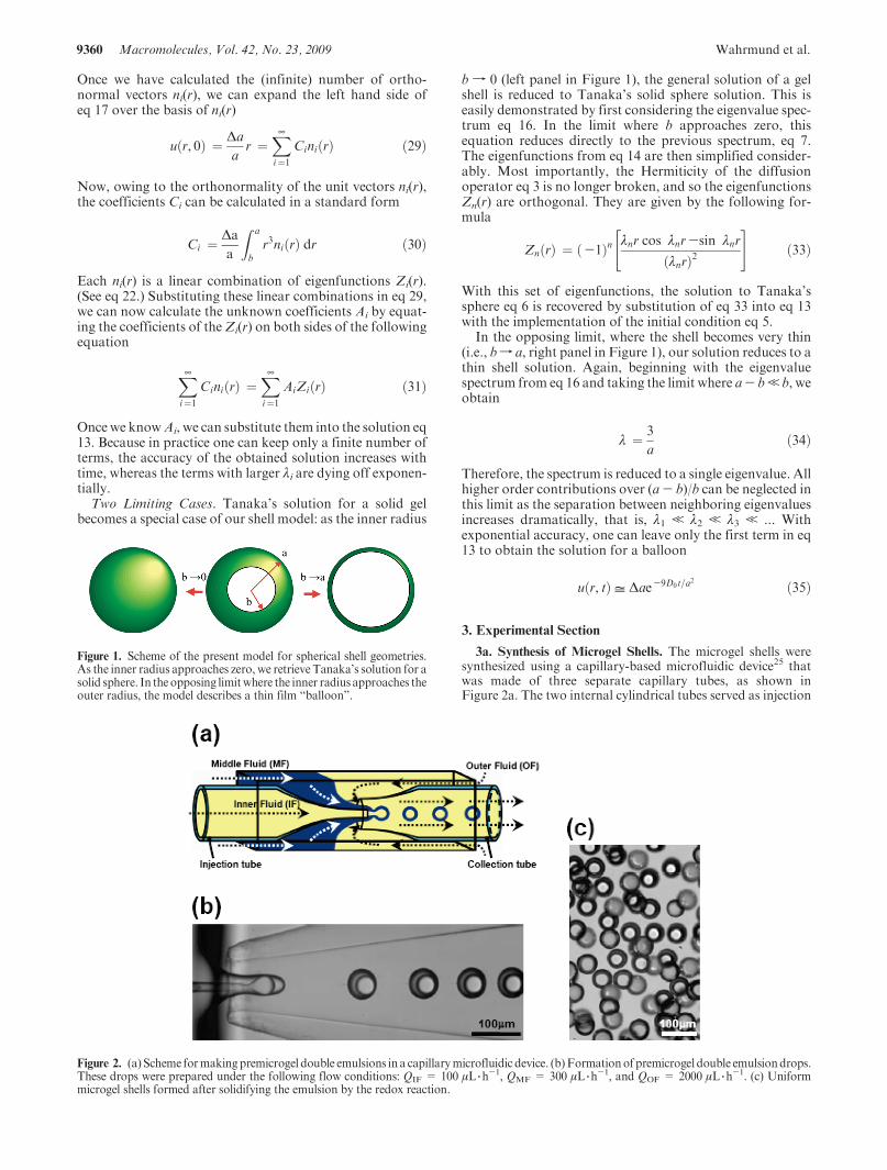
3a. Synthesis of Microgel Shells. The microgel shells weresynthesized using a capillary-based microfluidic device25 thatwas made of three separate capillary tubes, as shown inFigure 2a. The two internal cylindrical tubes served as injection
Figure 1. Scheme of the present model for spherical shell geometries.As the inner radius approaches zero, we retrieve Tanaka’s solution for asolid sphere. In the opposing limitwhere the inner radius approaches theouter radius, the model describes a thin film “balloon”.
Figure 2. (a) Scheme formakingpremicrogel double emulsions in a capillarymicrofluidic device. (b)Formationof premicrogel double emulsiondrops.These drops were prepared under the following flow conditions: QIF = 100 !L 3 h
-1, QMF = 300 !L 3h-1, and QOF = 2000 !L 3 h
-1. (c) Uniformmicrogel shells formed after solidifying the emulsion by the redox reaction.
Article Macromolecules, Vol. 42, No. 23, 2009 9361
and collection tubes and were coaxially aligned. In the regionnear both tips, the outer fluid focused both the middle and innerfluids through the collection tube to form a fluid thread thatthen breaks into drops because of hydrodynamic instabilities.When generating the microgel shell structure, we used siliconeoil (DC no. 550, density = 1.06 g 3mL-1)) with viscosity )OF =125 mPa 3 s as the inner fluid, which was immiscible with theaqueous middle fluid. The inner fluid consisted of DC no. 550and a reaction accelerator (N,N,N0,N0-tetramethylethylenedi-amine, 2 vol %). The drops pinched-off to produce uniformdouble emulsions, where each aqueous premicrogel drop con-tained a single oil droplet. The outer fluid (OF) was DC no. 550.The middle fluid (MF) for the batch 1 sample was an aqueousmonomer solution that contained the N-isopropylacrylamide(NIPAm, 15.5% w/v), a cross-linker (N,N0-methylenebisacryl-amide, BIS, 1.5% w/v), two comonomers (2-(methacryloyloxy)ethyl trimethyl ammonium chloride (METAC, 2 vol %), ally-lamine (1 vol%)), and an initiator (ammonium persulfate, APS,3% w/v). The initiator was located in the middle fluid, whereasthe accelerator was dissolved in the inner oil. The molar ratioofMETAC toNIPAMwas 5.6%. Themiddle fluid (MF) for thebatch 2 sample was the same as that for batch 1 except thatit contained less cross-linker (0.64% w/v BIS) and did notcontain METAC, which provided positive charges to the gelshell (batch 1).
Upon the formation of the double emulsion drops, theacclerator diffused from the internal oil droplet into the sur-rounding aqueous monomer solution layer, initiating the poly-merization. We matched the density of the water phase to 1.05g 3mL-1 by mixing glycerol (10 vol %) and deuterium oxide
(22 vol %). The flow rate (Q) conditions were QIF = 100!L 3 h
-1,QIF= 300 !L 3 h-1, andQIF= 2000 !L 3 h
-1. By tuningthe flow rates of the three fluid streams, we were able to producemicrogel particles at rates of !103 Hz. After we collected theparticles, they were washed repeatedly with large amounts ofisopropyl alcohol, which removed the silicon oil and weretransferred to deionized water. Swelling measurements werecarried out in water. Figure 2b shows the formation of pre-microgel double emulsion drops. Uniform microgel shells wereobtained after solidifying the emulsion by the redox reaction(Figure 2c). It is noted that when the inner and outer oils of theshells in Figure 2b,c were removed and the shells were placed in
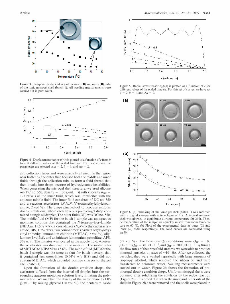
Figure 3. Temperature dependence of the inner (b) and outer (9) radiiof the ionic microgel shell (batch 1). All swelling measurements werecarried out in pure water.
Figure 4. Displacement vector u(r,t) is plotted as a function of r from bto a at different values of the scaled time t/*. For these curves, theparameters are selected as a = 2, b = 1, and !a = 2.
Figure 5. Radial stress tensor "rr(r,t) is plotted as a function of r fordifferent values of the scaled time t/*. For this set of curves, we have seta = 2, b = 1, and !a = 2.
Figure 6. (a) Shrinking of the ionic gel shell (batch 1) was recordedwith a digital camera with a time lapse of 1 s. A typical microgelshell was allowed to equilibrate at room temperature for 24 h. Then,he temperature of the sample was quickly raised from room tempera-ture to 60 !C. (b) Plots of the experimental data as outer (O) andinner (4) radii, respectively. The solid curves are calculated usingeq 36.

9362 Macromolecules, Vol. 42, No. 23, 2009 Wahrmund et al.
water, the sizes of the shells should approximately doublebecause of the hydrophilic nature of the polymer network.
3b. Observation of the Volume Phase Transition and SwellingKinetics. The volume phase transition of the microgel shells wasmonitored by the use of a bright field microscope (Leica)equipped with a digital camera (Hamamatsu, C4742-95) andSimple PCI acquisition software (Compix). For this, we com-pletely sealed the microgel shells in flat glass capillaries (innerdiameters !300 !m, VitroCom). Figure 3 shows temperature-dependent inner (b) and outer (9) radii for sample batch 1 inwater. The sharp volume change at !44 !C is determined to bethe transition temperature. This temperature is >34 !C forneutral PNIPAM gel because of the incorporation of ionicgroups from MATEC into the polymer network.
The PNIPAM microgel shells in pure water were put in atransparent holder on a glass slide, which was placed on amicroscope-mounted heating and cooling stage (PhysitempInstruments, TS-4ER) to examine the thermosensitive behavior.Several microgel shells with the same structures were measuredto obtain data with better statistics for the thermoresponsivecharacteristics. The temperature of the liquid inside the sampleholder was confirmed using an infrared thermometer (VWR).26
4. Results and Discussion
4a. Basic Theoretical Calculations. In Figure 4, we show anarbitrary solution to the radial displacement vector u(r,t) atvarious times as calculated by our model. The solution iscalculated up to the tenth order, and the parameters areselected to be a=2, b=1, and!a=2. Each of the curves isplotted as a function of the radius in the interval b< r< a.The times have been normalized to the first-order timeconstant in eq 13, * = 1/(D0#1
2). At the initial time t/* = 0,
the displacement u(r,t) is expressed as a nearly straight line asa function of r. Thewiggles are caused by the finite number ofterms in the series in eq 13. As t/* increases, the wigglesdisappear because the higher order terms are dying offexponentially.
Figure 5 shows a set of curves for the radial component ofthe stress tensor "rr(r,t), which is calculated by taking thesolution eq 13 and applying the differential operator de-scribed by eq 4. Because differentiation emphasizes anynonmonotonic features, the oscillations in Figure 5 are morepronounced as comparedwith those in Figure 4.We used thesame values for a, b, and!a as in Figure 4, andK=1 for thebulk modulus. According to the initial condition eq 5,swelling starts from uniform radial stress "rr(r,t = 0) =(3K!a)/a, whereas the eigenfunctionsZn(r) satisfy the stress-free boundary condition eq 4. A transition from uniformstress to zero stress occurs in the very initial stage of theevolution when the acceleration term cannot be neglected ineq 1. The length of this transient stage depends on the liquidviscosity, and it is usually very short as compared with thetypical relaxation time, *. Because we neglect the length ofthe transient stage, the numerical curve t = 0 in Figure 5obtained for a finite number of terms n = 10 tends to zeronear the inner surface r = b.
Li and Tanaka found the isotropic condition ur/r = uz/zfor a thin disk or a long cylinder gel, where ur/r and uz/z arethe relative swelling along the radial and longitudinal direc-tions, respectively.15 By minimizing shear elastic energy, weobtain the boundary condition, eq 12. At t/*f ¥, the radialstress "rr f 0 at both r = a and r = b and the isotropiccondition u(a,¥)/a = u(b,¥)/b is satisfied, as expected.
Figure 7. (a) Progress of swelling for the neutral microgel shell (batch 2) as the temperature jumpwas taken from 47 to 23 !C. Scale bar= 100 !m. (b)Graph shows the inner (4) and outer (O) radii of the gel shell radii versus elapsed time for a swelling process. The solid curves are calculated by ourmodel. (c) Temperature for the sample holder of this experiment versus time.

Article Macromolecules, Vol. 42, No. 23, 2009 9363
4b. Comparison with Experimental Data. A typical seriesof photos of shrinking kinetics for an ionic microgel shell(batch 1) is shown in Figure 6a. The experimental data forouter (O) and inner (4) radii are plotted in Figure 6b. Solidlines represent the evolution obtained for the outer radiusR (r= a,t) = a$ u(a,t) and the inner radiusR (b,t) = u(b,t)of the swelling (u<0) or shrinking (u>0) shell. To plot thedisplacements u(a,t) and u(b,t), we keep only the first term (n= 1) in eq 13, that is
R "r, t# ! r(X¥
n!1
AnZn"r#e-#2nD0t = r(A1Z1"r#e-t=* "36#
This approximation is valid at t> *when the terms with n>1 are exponentially small.
We present a further comparison of swelling and shrinkingresults for a neutral microgel shell (batch 2) that appear inFigures 7 and 8. Notice that some of the shells analyzed inthis study have a noticeable asymmetry. (See Figure 7a.)Because there is a good agreement between the theory andexperiment, we may assume that this slight asymmetry doesnot have much effect on the evolution of the gel shells.
For each of the fits performed here, we begin by identify-ing the necessary parameters from the experiment: theequilibrium shell radii (a and b) and the total change of theouter radius, !a. These parameters are then substituted intoeq 36. A nonlinear fit is employed to find the appropriatevalue for the collective diffusion coefficient,D0. The startingtime for the solution is selected on the basis of the tempera-ture measurements within the sample holder. We can seefrom the temperature curves in Figures 7c and 8c that the
change of temperature within the sample holder occurs on atime scale that is comparable to that of the swelling (orshrinking) time scales. In the ideal situation, this comparisonis done such that the heating time for the sample holder ismuch smaller than that of the swelling time. Because thediffusion coefficient is temperature dependent, the start timemust be selected appropriately to ensure that the fit is donewithin the time scale where the temperature gradient isnegligible. Start times are selected by inspection of the dataand are chosen by the point where the temperature stabilizes.
Using the data shown in Figure 6, we have found thecollective diffusion coefficient D0 = 5.7 ( 10-8 cm2
3 s-1 for
the shrinking experiment for the ionic microgel shell (batch1) at 60 !C in Figure 6. The shrinking kinetics for submilli-meter ionic solid gel spheres have been previously studiedwith three characteristic processes: initially the gel shrinksand maintains its spherical shape, then the shrinking stops(known as a plateau period), and finally bubbles appear onthe surface of the gel.28 As shown in Figure 6a, our shelluniformly shrank from the beginning to the end without thedevelopment of the transient surface pattern. This suggeststhat for a very small gel such as amicrogel shell there appearsnomechanical instability due to a large volume change in theshrinking process that can cause surface patterns.
For the neutral microgel shell (batch 2), we found thatD0= 2.0( 10-7 cm2
3 s-1 for swelling at 23 !C (Figure 7) and
D0 = 1.1 ( 10-7 cm23 s-1 for shrinking at 47 !C (Figure 8).
These values are in excellent agreement with the previousmeasurements made for neutral PNIPAM submillimetersolid gel spheres that did not have a transient surface patternduring shrinking at each of the respective temperatures.
Figure 8. (a) Progress of shrinking for the neutralmicrogel shell (batch 2) as the temperature jumpwas taken from 23 to 47 !C. Scale bar=100 !m. (b)Graph shows the inner (4) and outer (O) radii of the gel shell radii versus elapsed time for a shrinking process. The solid curves are calculated by ourmodel. (c) The temperature for the sample holder of this experiment versus time.

9364 Macromolecules, Vol. 42, No. 23, 2009 Wahrmund et al.
These previous measurements showed that D0 = 2.0 (10-7 cm2
3 s-1 at 23 !C and D0 = 1.6 ( 10-7 cm2
3 s-1 at
47 !C.294c. Comparison of a Solid Sphere with a Shell. For a
diffusion process, the time required for matter to diffuseat some distance changes quadratically with the distance.In particular, the solution obtained for a solid spheregives11
* " a2=D0 "37#
For a shell, one can expect that *shell" (a- b)2. However, ourresults show that *shell" a2. That is, the characteristic time ofa gel shell should be proportional to the square of the outerradius, not to the squared thickness of the shell. Indeed, for athin shell (balloon) when (a- b)f 0, the characteristic timeremains finite, and according to eq 35
*shell !1
#2D0
! a2
9D0"38#
For a solid sphere (b=0), the characteristic time is given bythe lowest eigenvalue in the spectrum eq 7, #1 = $/a
*solid ! 1
#21D0
! a2
$2D0"39#
For the intermediate case, when 0 < a - b < a the lowesteigenvalue #1 obtained from eq 16 lies between 2.9/a and $/a,as plotted in Figure 9. Because the relative variation of #1versus a- b does not exceed 4%, we may conclude that for ashell the characteristic time is approximately proportional toa2. We suggest that the relationship of *" a2 is caused by theconstraint imposed at the inner boundary eq 12. In contrastwith the outer shell, which is always stress-free, there is alarge increase in the stress at the inner surface soon after theshell starts to swell. This stress constrains the gel shell to swellslower for the readjustment of shape necessary to minimizethe shear energy integral eq 10.
From the plot in Figure 9 and the relation *" 1/#12, one can
conclude that the solid sphere swells a bit faster than a shell.However, the difference in the characteristic times is less than0.01a2/D0. Such a small difference is hard to detect experi-mentally.
To investigate the above results further, we have re-examined the swelling and shrinking kinetics data that werepublished in ref 26 and adapted in Figure 10. Here swelling(Figure 10a) and shrinking kinetics (Figure 10b) between asolid microgel (series A) and a gel shell (series B) arecompared. There is no discernible difference between thesolid sphere and a gel shell just by visual inspection.
A comparison of the relative displacements for the sphereand the shell as a function of time are shown in Figure 11. Asan approximation, we have used the first time exponentialterm e-t/* to fit both curves.We find that the values of * in theshrinking process are 10.1( 1.2 and 12.2( 1.2 s for the solidsphere and the shell, respectively, as shown in Figure 11a. Inthe case of swelling (Figure 11b), the characteristic times arecalculated to be 52 ( 2 and 56 ( 4 s for the solid sphere and
Figure 9. First eigenvalue solution to eq 16 plotted as a#1 versus theratio (b/a) of the inner radius (b) to the outer radius (a). The dashed linesshow two limiting cases: as b f 0 (a solid sphere), #1 f $; as b f a (aballoon), a#1 f 3.
Figure 10. Comparison of swelling kinetics between a solid microgel(A) and a microgel shell (B) upon (a) heating from 23 to 47 !C and (b)cooling from 47 to 23 !C. Scale bar = 100 !m.
Figure 11. Comparison of the relative displacements for the solidmicrogel sphere (4) and the microgel shell (O) as a function of time:for the (a) shrinking and (b) swelling processes, respectively.

Article Macromolecules, Vol. 42, No. 23, 2009 9365
shell, respectively. These characteristic times are very close toone another. It may appear that the shell swells slower thanthe solid sphere, but with the experimental error taken intoaccount, we cannot conclude any quantitative differencebetween the two.
5. Conclusions
We have built a theoretical model for the swelling kinetics of apolymer gel shell by considering the shell with outer and innerradii a and b, respectively. For the outer layer, there is the samefree surface boundary condition as that for a solid gel sphere. Theboundary condition at the inner surface is obtained from theminimization of shear elastic energy. We solved the diffusionequation for the displacement vector u(r,t) with two boundaryconditions and with the initial condition of uniform stress at t=0.Our results recover the solution to Tanaka andFillmore’s solidsphere solution as bf 0. In the opposite limiting case, bf a, wefind that the swelling of a thin shell like a balloon is describedsimply by a single exponential term.
To test our theoretical model, we have made monodispersePNIPAM polymer gel shells using a microfluidic device. Thesegels typically have an inner radius of!40 !m and an outer radiusof !60 !m. By switching temperatures, we have measured theinner and outer radii of the shell as a function of time and havefound the collective diffusion coefficient for the shrinking experi-ment for the ionic microgel shell (batch 1) at 60 !C to be D0 =5.7 ( 10-8 cm2
3 s-1. The shell uniformly shrank from the
beginning to the end without the development of the transientsurface pattern. For the neutral microgel shell (batch 2), thediffusion coefficients are found to be D0 = 2.0 ( 10-7 cm2
3 s-1
for swelling at 23 !C andD0 = 1.1( 10-7 cm23 s-1 for shrinking
at 47 !C. These values are in agreement with the previousmeasurements made for neutral PNIPAM submillimeter solidgel spheres at each of the respective temperatures: D0 = 2.0 (10-7 cm2
3 s-1 at 23 !C andD0 = 1.6( 10-7 cm2
3 s-1 at 47 !C.29
Our model shows that the characteristic time of a gel shell isproportional to the square of the outer radius, not to the square ofthe thickness of the shell. This is because both boundaries arecoupled via the boundary condition that originates from theminimization of shear elastic energy. This conclusion is con-firmed by experimental observation of swelling kinetics. Ourmodel further predicts that the solid sphere swells slightly fasterthan the gel shell if they have the same outer radius. Theexperiments nearly confirm this tendency, although the lack of
experimental accuracy does not allow for a reasonable quantita-tive comparison.
Acknowledgment. The work at University of North Texaswas supported by the NSF (DMR-0805089, Z.H.) and the DOE(DE-FG02-06ER46312, A.K.), and the work at Harvard wassupported by theNSF (DMR-0602684) and theHarvardMateri-als Research Science and Engineering Center (DMR-0820484).A.F-N. thanks Junta de Andalucia (FQM-0.116).
References and Notes
(1) Peppas, N. A. Hydrogels in Medicine and Pharmacy; CRC Press:Boca Raton, FL, 1987.
(2) Hoffman, A. S. J. Controlled Release 1987, 6, 297.(3) Li, Y.; Tanaka, T. Annu. Rev. Mater. Sci. 1992, 22, 243.(4) Siegel, R. Adv. Polym. Sci. 1993, 109, 233.(5) Shibayama, M.; Tanaka, T. Adv. Polym. Sci. 1993, 109, 1.(6) Gehrke, S. H. Adv. Polym. Sci. 1993, 110, 81.(7) Hu, Z.; Zhang, X.; Li, Y. Science 1995, 269, 525.(8) Osada, Y.; Gong, J. P. Adv. Mater. 1999, 10, 827.(9) Flory, P. J.; Rehner, J. J. Chem. Phys. 1943, 11, 521.
(10) Ritger, P. L.; Peppas, N. A. J. Controlled Release 1987, 5, 37.(11) Tanaka, T.; Fillmore, D. J. J. Chem. Phys. 1979, 70, 1214.(12) Tanaka, T.; Hocker, L. O.; Benedek, G. B. J. Chem. Phys. 1973, 59,
5151.(13) Peters, A.; Candau, S. J. Macromolecules 1986, 19, 1952.(14) Peters, A.; Candau, S. J. Macromolecules 1988, 21, 2278.(15) Li, Y.; Tanaka, T. J. Chem. Phys. 1990, 92, 1365.(16) Wang, C. J.; Li, Y.; Hu, Z. B. Macromolecules 1997, 30, 4727.(17) Urayama, K.; Okada, S.; Nosaka, S.; Watanabe, H.; Takigawa, T.
J. Chem. Phys. 2005, 122, 024906.(18) Yamaue, T.; Doi, M. J. Chem. Phys. 2005, 122, 084703.(19) Doi, M. J. Phys. Soc. Jpn. 2009, 78, 052001.(20) Birgersson, E.; Li, H.; Wu, S. J. Mech. Phys. Solids 2008, 56, 444.(21) Ichikawa, H.; Fukumori, Y. J. Controlled Release 2000, 63, 107.(22) Koh, W. G.; Revzin, A.; Pishko, M. V. Langmuir 2002, 18, 2459.(23) Gu, J.; Xia, F.; Wu, Y.; Qu, X.; Yang, Z.; Jiang, L. J. Controlled
Release 2007, 117, 396.(24) Lawrence, D. B.; Cai, T.; Hu, Z.; Marquez, M.; Dinsmore, A. D.
Langmuir 2007, 23, 395.(25) Kim, J.-W.; Utada, A. S.; Fernandez-Nieves, A.; Hu, Z. B.; Weitz,
D. A. Angew. Chem., Int. Ed. 2007, 46, 1819–22.(26) Chu, L.-Y.; Kim, J.-W.; Shah, R. K.; Weitz, D. A. Adv. Funct.
Mater. 2007, 17, 3499–3504.(27) Trefethen,L.N.; Bau,D., III.NumericalLinearAlgebra; Society for
Industrial and Applied Mathematics: Philadelphia, PA, 1997.(28) Sato Matsuo, E.; Tanaka, T. J. Chem. Phys. 1988, 89, 1965–1703.(29) Tanaka, T.; SatoMatsuo, E.; Hirokawa, Y.; Hirotsu, S.; Peetermans,
J. Phys. Rev. Lett. 1985, 55, 2455–2458.