swe202 review. processes process state as a process executes, it changes state – new: the process...
TRANSCRIPT

SWE202 ReviewSWE202 Review

Processes
Process State
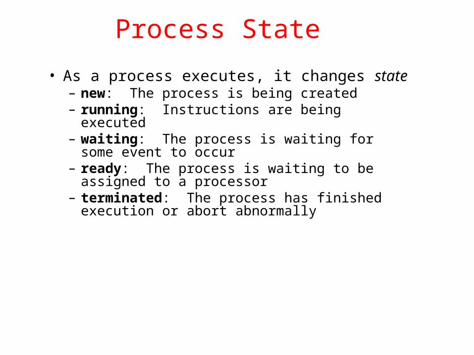
• As a process executes, it changes state– new: The process is being created– running: Instructions are being executed– waiting: The process is waiting for some event to
occur– ready: The process is waiting to be assigned to a
processor– terminated: The process has finished execution
or abort abnormally

Diagram of Process State
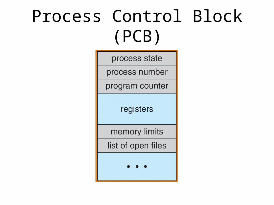
Process Control Block (PCB)

CPU Switch From Process to Process

Ready Queue And Various I/O Device Queues

Schedulers• Long-term scheduler (or job scheduler) – selects
which processes should be brought into the ready queue. Most of the process/job is on secondary memory storage such as: disk drive, etc. Such process/job will be swapped in/out of the system memory whenever it is necessary to do so.
• Short-term scheduler (or CPU scheduler) – selects which process should be executed next and allocates CPU to execute the process. All of these processes will be in system memory and ready to be executed by CPU.
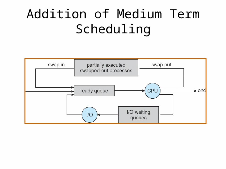
Addition of Medium Term Scheduling

Context Switch• When CPU switches to another process, the system
must save the state of the old process and load the saved state for the new process. Context switching operation is done by hardware, it is relatively working faster than software operation.
• Context-switch time is the additional waste overhead; the system does no useful work while switching. In other words, no CPU execution during the period of context switching from current process to new process.
• Time dependent on context switching hardware support
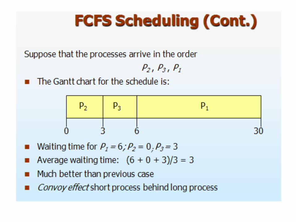
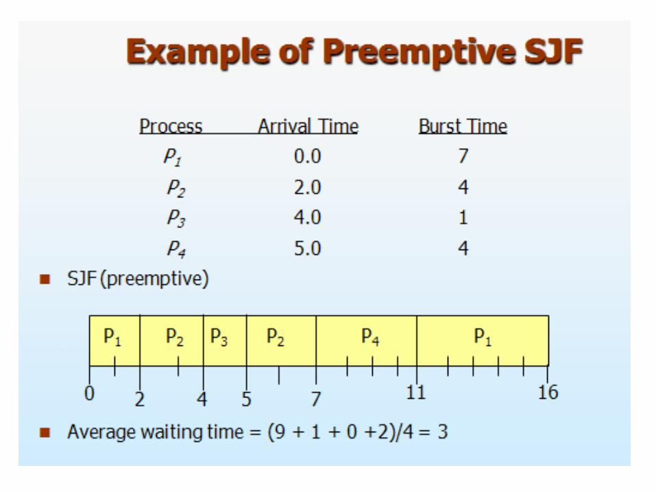
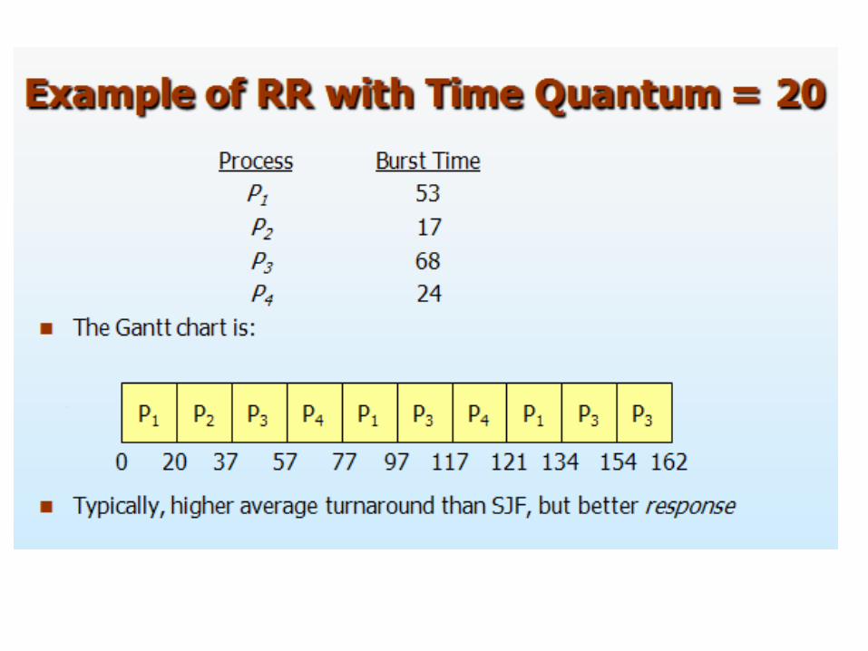
CPU Scheduling


Deadlocks
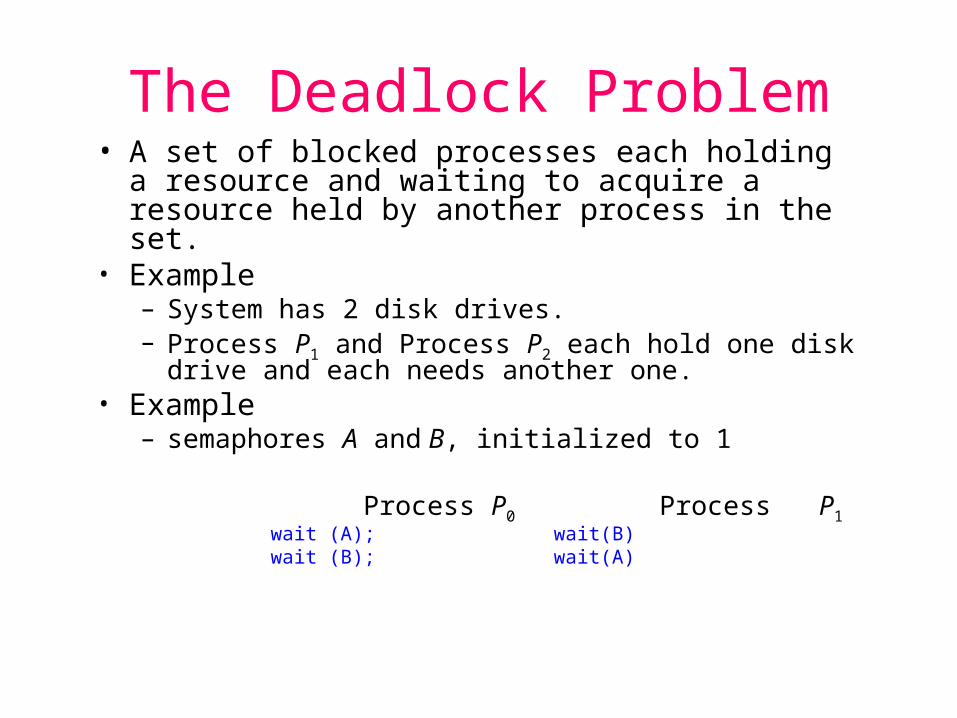
The Deadlock Problem• A set of blocked processes each holding a resource
and waiting to acquire a resource held by another process in the set.
• Example – System has 2 disk drives.– Process P1 and Process P2 each hold one disk drive and
each needs another one.• Example
– semaphores A and B, initialized to 1
Process P0 Process P1wait (A); wait(B)wait (B); wait(A)
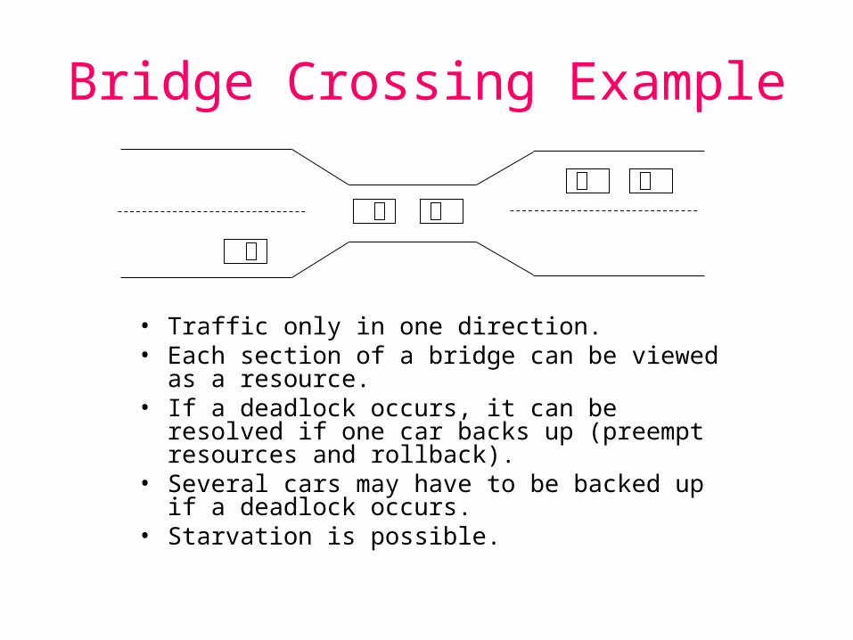
Bridge Crossing Example
• Traffic only in one direction.• Each section of a bridge can be viewed as a resource.• If a deadlock occurs, it can be resolved if one car
backs up (preempt resources and rollback).• Several cars may have to be backed up if a deadlock
occurs.• Starvation is possible.
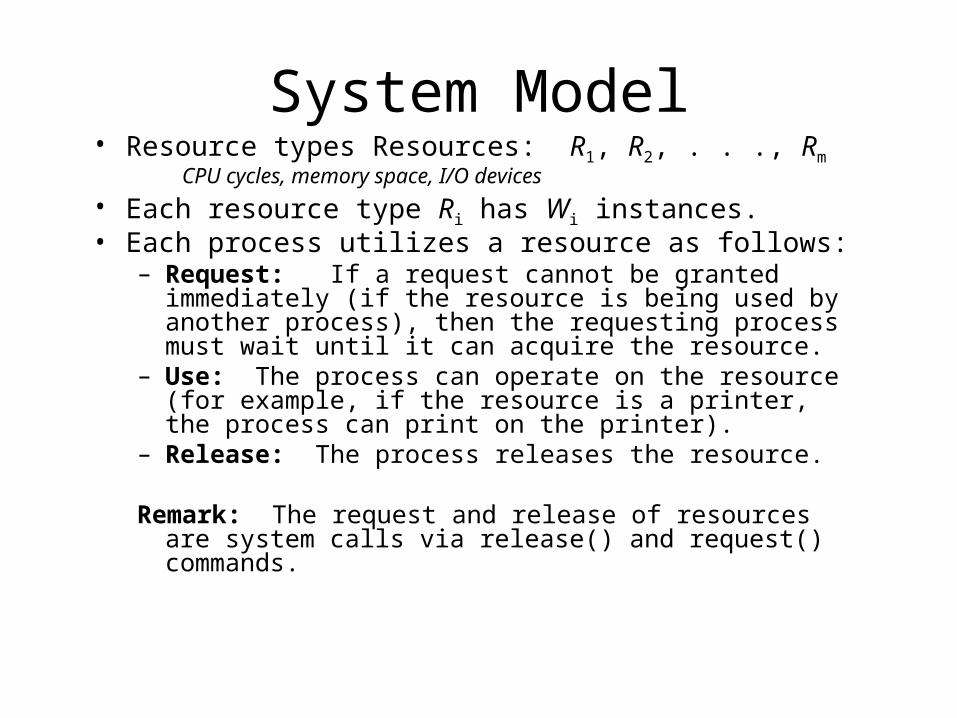
System Model• Resource types Resources: R1, R2, . . ., Rm
CPU cycles, memory space, I/O devices• Each resource type Ri has Wi instances.• Each process utilizes a resource as follows:
– Request: If a request cannot be granted immediately (if the resource is being used by another process), then the requesting process must wait until it can acquire the resource.
– Use: The process can operate on the resource (for example, if the resource is a printer, the process can print on the printer).
– Release: The process releases the resource.
Remark: The request and release of resources are system calls via release() and request() commands.
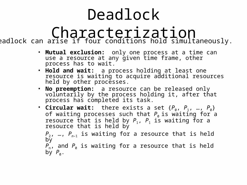
Deadlock Characterization
• Mutual exclusion: only one process at a time can use a resource at any given time frame, other process has to wait.
• Hold and wait: a process holding at least one resource is waiting to acquire additional resources held by other processes.
• No preemption: a resource can be released only voluntarily by the process holding it, after that process has completed its task.
• Circular wait: there exists a set {P0, P1, …, P0} of waiting processes such that P0 is waiting for a resource that is held by P1, P1 is waiting for a resource that is held by P2, …, Pn–1 is waiting for a resource that is held by Pn, and P0 is waiting for a resource that is held by P0.
Deadlock can arise if four conditions hold simultaneously.
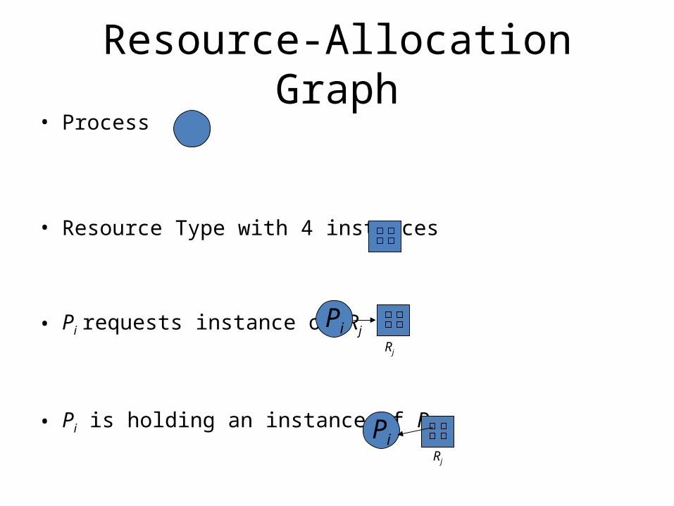
Resource-Allocation Graph• Process
• Resource Type with 4 instances
• Pi requests instance of Rj
• Pi is holding an instance of Rj
PiRj
PiRj
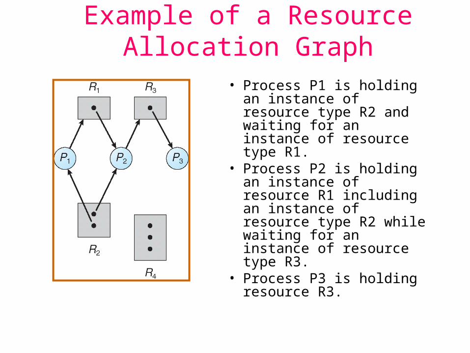
Example of a Resource Allocation Graph• Process P1 is holding an
instance of resource type R2 and waiting for an instance of resource type R1.
• Process P2 is holding an instance of resource R1 including an instance of resource type R2 while waiting for an instance of resource type R3.
• Process P3 is holding resource R3.

Resource Allocation Graph With A Deadlock
Process P1 is holding an instance of resource type R2 and waiting for an instance of resource type R1.
Process P2 is holding an instance of resource R1 including an instance of resource type R2 while waiting for an instance of resource type R3.
Process P3 is holding an instance of resource type R3 and now requesting additional instance of resource type R2.
Create circular deadlock condition.

Graph With A Cycle But No Deadlock
Circular deadlock can be released.
If process P2 finishes its process with the instance of resource type R1. Process P1 can then use the released instance of resource type R1 and proceed to finish its own process.
If process P4 finishes its process with the instance of resource type R2. Process P3 can then use the released instance of resource type R2 and proceed to finish its own process.
Basic Facts on deadlock condition• If graph contains no cycles no deadlock.
• If graph contains a cycle – if only one instance per resource type, then
deadlock ( a definite circular deadlock.– if several instances per resource type, there is
a possibility of deadlock (if it is not a circular deadlock, it can be resolved later on).

Methods for Handling Deadlocks• Use a protocol to prevent or avoid deadlock to ensure that
the system will never enter a deadlock state.
• Allow the system to enter a deadlock state, detect it and then recover from it.
• Ignore the problem and pretend that deadlocks never occur in the system; used by most operating systems, including UNIX and Windows.
• The operating system will provide information regarding to the status of all its resources. It is up to the application developer to write programs that handle any possible deadlocks.
Deadlock Prevention
• Mutual Exclusion – must hold for nonsharable resources.For example, Read-only files can be shared among processes. Mutual Exclusion doesn’t address the sharable issues.
• Hold and Wait – must guarantee that whenever a process requests a resource, it does not hold any other resources.– Require process to request and be allocated all its resources
before it begins execution.– Before it can request additional resources, however, it must
release all resources that it is currently allocated.– Allow process to request resources only when the process has
none.– Low resource utilization; starvation possible if most of the
processes need the same resource.
Restrain the ways request can be made.

Deadlock Prevention (Cont.)• No Preemption –
– If a process that is holding some resources requests another resource that cannot be immediately allocated to it, then all resources currently being held are released.
– Preempted resources are added to the list of resources for which the process is waiting.
– Process will be restarted only when it can regain its old resources, as well as the new ones that it is requesting.
– This protocol cannot generally be applied to such resources as printers and tape drives.
• Circular Wait – impose a total ordering of all resource types, and require that each process requests resources in an increasing order of enumeration. It is up to the application developer to impose the above circular wait algorithm.

Deadlock Avoidance
• Simplest and most useful model requires that each process declare the maximum number of resources of each type that it may need.
• The deadlock-avoidance algorithm dynamically examines the resource-allocation state to ensure that there can never be a circular-wait condition.
• Resource-allocation state is defined by the number of available and allocated resources, and the maximum demands of the processes.
Requires that the system has some additional a priori information available.

Safe State• When a process requests an available resource, system must
decide if immediate allocation leaves the system in a safe state.
• System is in safe state if there exists a sequence <P1, P2, …, Pn> of ALL the processes is the systems such that for each Pi, the resources that Pi can still request can be satisfied by currently available resources + resources held by all the Pj, with j < i.
• That is:– If Pi resource needs are not immediately available, then Pi can
wait until all Pj have finished.– When Pj is finished, Pi can obtain needed resources, execute,
return allocated resources, and terminate. – When Pi terminates, Pi +1 can obtain its needed resources, and
so on.

Typical Avoidance algorithms• Single instance of a resource type. Use a resource-
allocation graph
• Multiple instances of a resource type. Use the banker’s algorithm
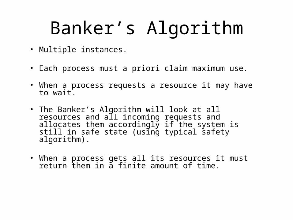
Banker’s Algorithm• Multiple instances.
• Each process must a priori claim maximum use.
• When a process requests a resource it may have to wait.
• The Banker’s Algorithm will look at all resources and all incoming requests and allocates them accordingly if the system is still in safe state (using typical safety algorithm).
• When a process gets all its resources it must return them in a finite amount of time.

Virtual Memory
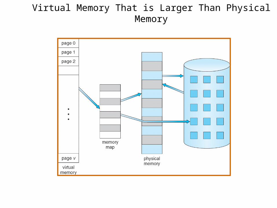
Virtual Memory That is Larger Than Physical Memory

Demand Paging• Bring a page into memory only when it is needed (for
execution)– Less I/O needed– Less memory needed – Faster response– More users
• Page is needed reference to it– invalid reference abort– not-in-memory bring to memory
• Lazy swapper – never swaps a page into memory unless page will be needed– Swapper that deals with pages is a pager
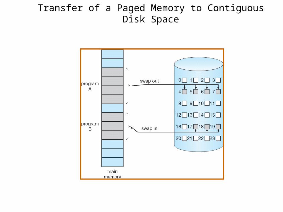
Transfer of a Paged Memory to Contiguous Disk Space

Valid-Invalid Bit• With each page table entry a valid–invalid bit is associated
(v in-memory, i not-in-memory)• Initially valid–invalid bit is set to i on all entries• Example of a page table snapshot:
• During address translation, if valid–invalid bit in page table entry is I page fault
vvvvi
ii
….
Frame # valid-invalid bit
page table
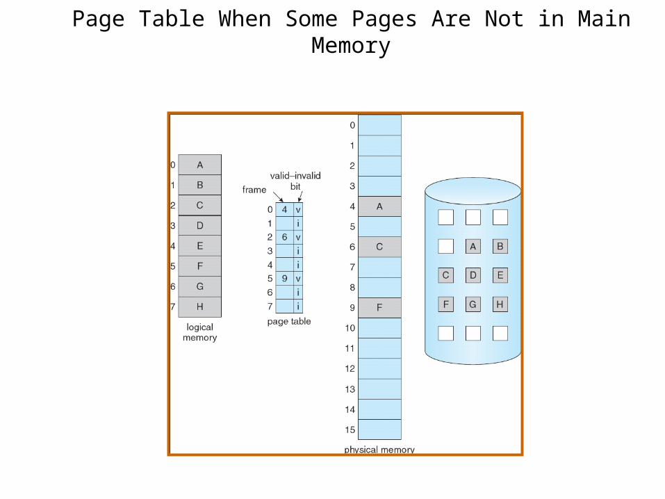
Page Table When Some Pages Are Not in Main Memory
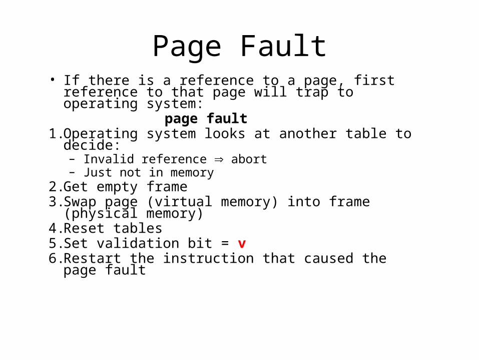
Page Fault• If there is a reference to a page, first reference to
that page will trap to operating system: page fault1. Operating system looks at another table to decide:
– Invalid reference abort– Just not in memory
2. Get empty frame3. Swap page (virtual memory) into frame (physical
memory)4. Reset tables5. Set validation bit = v6. Restart the instruction that caused the page fault

Steps in Handling a Page Fault
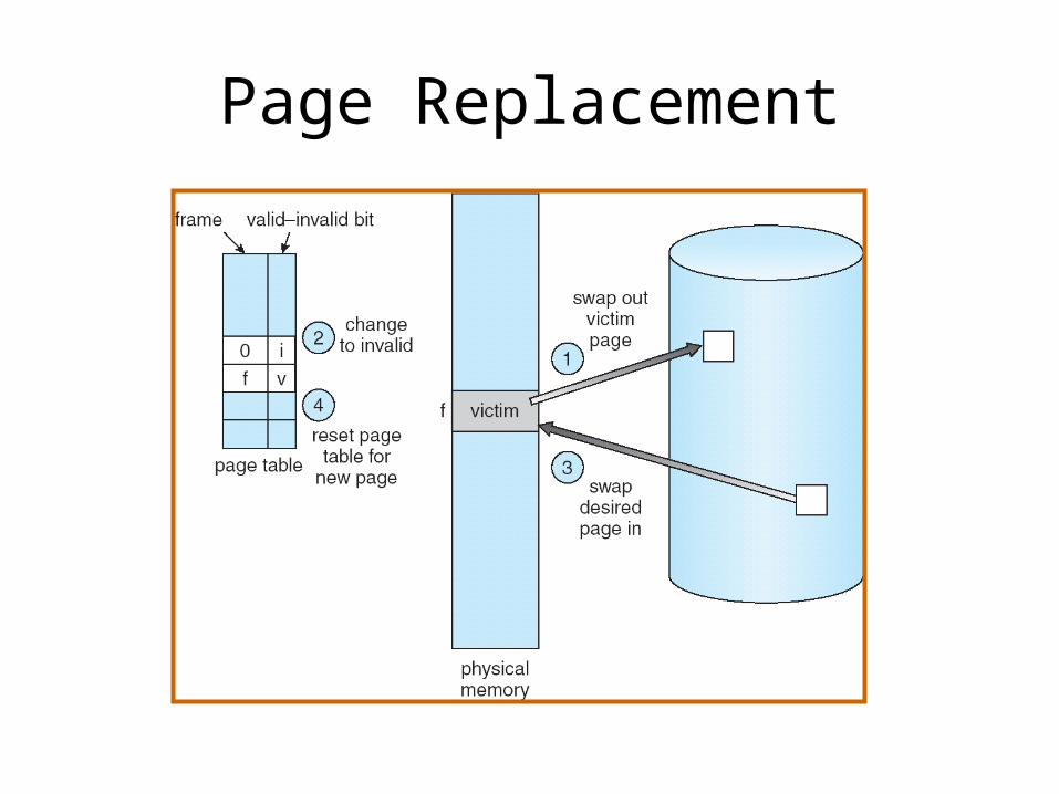
Page Replacement
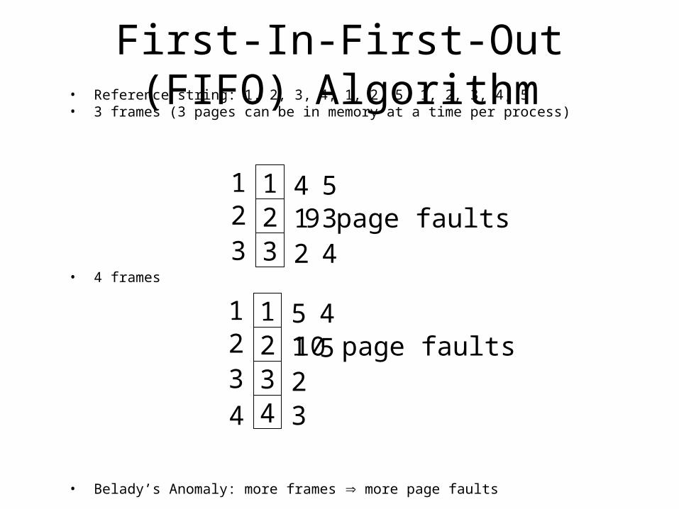
First-In-First-Out (FIFO) Algorithm• Reference string: 1, 2, 3, 4, 1, 2, 5, 1, 2, 3, 4, 5• 3 frames (3 pages can be in memory at a time per process)
• 4 frames
• Belady’s Anomaly: more frames more page faults
123
123
412
534
9 page faults
123
123
512
4510 page faults
44 3
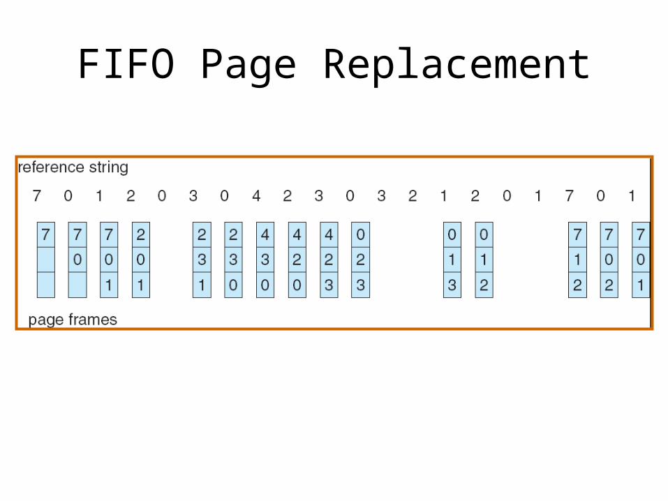
FIFO Page Replacement

Optimal Page Replacement
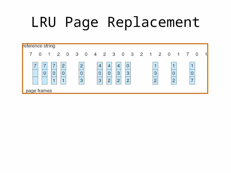
LRU Page Replacement
Thrashing• If a process does not have “enough” pages,
the page-fault rate is very high. This leads to:– low CPU utilization– operating system thinks that it needs to
increase the degree of multiprogramming– another process added to the system
• Thrashing a process is busy swapping pages in and out
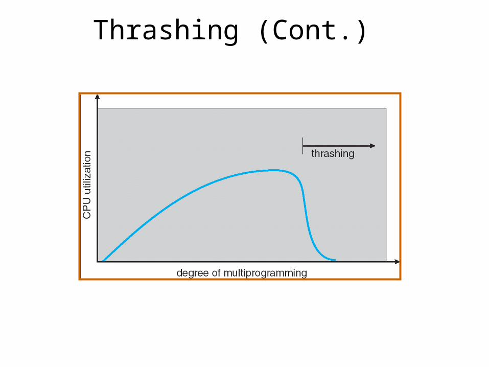
Thrashing (Cont.)

Q&AQ&A
