suse linux enterprise server documentation - novell · 13.2 installing isns server for linux ......
TRANSCRIPT

SUSE LinuxEnterprise Server 11SP4
www.suse.com
May 12, 2015 Storage Administration Guide

Storage Administration GuideLegal Notices
Copyright © 2006–2015 SUSE Linux GmbH. and contributors. All rights reserved.
Permission is granted to copy, distribute and/or modify this document under the terms of the GNUFree Documentation License, Version 1.2 or (at your option) version 1.3; with the Invariant Sectionbeing this copyright notice and license. A copy of the license version 1.2 is included in the sectionentitled “GNU Free Documentation License”.
All information found in this book has been compiled with utmost attention to detail. However, thisdoes not guarantee complete accuracy. Neither SUSE LINUX GmbH, the authors, nor the transla-tors shall be held liable for possible errors or the consequences thereof.
Trademarks
For Novell trademarks, see the Novell Trademark and Service Mark list [http://www.novell.com/company/legal/trademarks/tmlist.html].Linux* is a registered trademark of Linus Torvalds. All other third party trademarks are the propertyof their respective owners.A trademark symbol (®, ™, etc.) denotes a Novell trademark; an asterisk (*) denotes a third partytrademark.

ContentsAbout This Guide xi
1 Overview of File Systems in Linux 11.1 Terminology ........................................................................................ 2
1.2 Major File Systems in Linux ................................................................. 2
1.3 Other Supported File Systems .............................................................. 18
1.4 Large File Support in Linux ................................................................ 19
1.5 Linux Kernel Storage Limitations ......................................................... 21
1.6 Managing Devices with the YaST Partitioner ......................................... 22
1.7 Additional Information ........................................................................ 22
2 What’s New for Storage in SLES 11 252.1 What’s New in SLES 11 SP4 ............................................................... 25
2.2 What’s New in SLES 11 SP3 ............................................................... 25
2.3 What’s New in SLES 11 SP2 ............................................................... 30
2.4 What’s New in SLES 11 SP1 ............................................................... 31
2.5 What’s New in SLES 11 ...................................................................... 35
3 Planning a Storage Solution 433.1 Partitioning Devices ............................................................................ 43
3.2 Multipath Support .............................................................................. 43
3.3 Software RAID Support ...................................................................... 44
3.4 File System Snapshots ......................................................................... 44
3.5 Backup and Antivirus Support .............................................................. 44
4 LVM Configuration 474.1 Understanding the Logical Volume Manager .......................................... 48
4.2 Creating LVM Partitions ..................................................................... 50
4.3 Creating Volume Groups ..................................................................... 52
4.4 Configuring Physical Volumes ............................................................. 54
4.5 Configuring Logical Volumes .............................................................. 56
4.6 Automatically Activating Non-Root LVM Volume Groups ....................... 60
4.7 Tagging LVM2 Storage Objects ........................................................... 61
4.8 Resizing a Volume Group ................................................................... 69
4.9 Resizing a Logical Volume with YaST .................................................. 71
4.10 Resizing a Logical Volume with Commands ......................................... 72
4.11 Deleting a Volume Group .................................................................. 73
4.12 Deleting an LVM Partition (Physical Volume) ...................................... 74
4.13 Using LVM Commands ..................................................................... 74
5 Resizing File Systems 795.1 Guidelines for Resizing ....................................................................... 79
5.2 Increasing the Size of an Ext2, Ext3, or Ext4 File System ......................... 81
5.3 Increasing the Size of a Reiser File System ............................................ 82
5.4 Decreasing the Size of an Ext2 or Ext3 File System ................................ 83
5.5 Decreasing the Size of a Reiser File System ........................................... 84
6 Using UUIDs to Mount Devices 876.1 Naming Devices with udev .................................................................. 87
6.2 Understanding UUIDs ......................................................................... 88
6.3 Using UUIDs in the Boot Loader and /etc/fstab File (x86) ........................ 89
6.4 Using UUIDs in the Boot Loader and /etc/fstab File (IA64) ...................... 91

6.5 Additional Information ........................................................................ 93
7 Managing Multipath I/O for Devices 957.1 Understanding Multipath I/O ............................................................... 96
7.2 Planning for Multipathing .................................................................... 96
7.3 Multipath Management Tools ............................................................. 113
7.4 Configuring the System for Multipathing ............................................. 126
7.5 Enabling and Starting Multipath I/O Services ....................................... 130
7.6 Creating or Modifying the /etc/multipath.conf File ................................ 131
7.7 Configuring Default Policies for Polling, Queueing, and Failback ............ 136
7.8 Blacklisting Non-Multipath Devices .................................................... 138
7.9 Configuring User-Friendly Names or Alias Names ................................ 140
7.10 Configuring Default Settings for zSeries Devices ................................. 144
7.11 Configuring Path Failover Policies and Priorities ................................. 145
7.12 Configuring Multipath I/O for the Root Device ................................... 162
7.13 Configuring Multipath I/O for an Existing Software RAID ................... 167
7.14 Scanning for New Devices without Rebooting ..................................... 170
7.15 Scanning for New Partitioned Devices without Rebooting ..................... 173
7.16 Viewing Multipath I/O Status ........................................................... 175
7.17 Managing I/O in Error Situations ...................................................... 177
7.18 Resolving Stalled I/O ....................................................................... 178
7.19 Troubleshooting MPIO .................................................................... 179
7.20 What’s Next ................................................................................... 181
8 Software RAID Configuration 1838.1 Understanding RAID Levels .............................................................. 184
8.2 Soft RAID Configuration with YaST .................................................. 186
8.3 Troubleshooting Software RAIDs ....................................................... 188
8.4 For More Information ....................................................................... 189

9 Configuring Software RAID1 for the Root Partition 1919.1 Prerequisites for Using a Software RAID1 Device for the Root Partition ............................................................................................................. 191
9.2 Enabling iSCSI Initiator Support at Install Time .................................... 192
9.3 Enabling Multipath I/O Support at Install Time ..................................... 193
9.4 Creating a Software RAID1 Device for the Root (/) Partition .................. 193
10 Managing Software RAIDs 6 and 10 with mdadm 19910.1 Creating a RAID 6 .......................................................................... 199
10.2 Creating Nested RAID 10 Devices with mdadm .................................. 201
10.3 Creating a Complex RAID 10 .......................................................... 206
10.4 Creating a Degraded RAID Array ..................................................... 216
11 Resizing Software RAID Arrays with mdadm 21911.1 Understanding the Resizing Process ................................................... 219
11.2 Increasing the Size of a Software RAID ............................................. 221
11.3 Decreasing the Size of a Software RAID ............................................ 227
12 Storage Enclosure LED Utilities for MD SoftwareRAIDs 23512.1 Supported LED Management Protocols .............................................. 236
12.2 Supported Storage Enclosure Systems ................................................ 236
12.3 Storage Enclosure LED Monitor Service (ledmon(8)) ........................... 236
12.4 Storage Enclosure LED Control Application (ledctl(8)) ........................ 238
12.5 Enclosure LED Utilities Configuration File (ledctl.conf(5)) ................... 244
12.6 Additional Information .................................................................... 245
13 iSNS for Linux 24713.1 How iSNS Works ........................................................................... 248

13.2 Installing iSNS Server for Linux ....................................................... 249
13.3 Configuring iSNS Discovery Domains ............................................... 251
13.4 Starting iSNS ................................................................................. 258
13.5 Stopping iSNS ................................................................................ 258
13.6 For More Information ..................................................................... 259
14 Mass Storage over IP Networks: iSCSI 26114.1 Installing iSCSI Target and Initiator .................................................. 263
14.2 Setting Up an iSCSI Target .............................................................. 264
14.3 Configuring iSCSI Initiator .............................................................. 275
14.4 Using iSCSI Disks when Installing .................................................... 282
14.5 Troubleshooting iSCSI ..................................................................... 282
14.6 Additional Information .................................................................... 285
15 Mass Storage over IP Networks: iSCSI LIO TargetServer 28715.1 Installing the iSCSI LIO Target Server Software ................................. 288
15.2 Starting the iSCSI LIO Target Service ............................................... 291
15.3 Configuring Authentication for Discovery of iSCSI LIO Targets and Clients ............................................................................................................. 295
15.4 Preparing the Storage Space ............................................................. 299
15.5 Setting Up an iSCSI LIO Target Group .............................................. 302
15.6 Modifying an iSCSI LIO Target Group .............................................. 312
15.7 Deleting an iSCSI LIO Target Group ................................................. 315
15.8 Troubleshooting iSCSI LIO Target Server .......................................... 317
15.9 iSCSI LIO Target Terminology ......................................................... 318
16 Fibre Channel Storage over Ethernet Networks: FCoE 32116.1 Installing FCoE and the YaST FCoE Client ........................................ 323

16.2 Configuring FCoE Interfaces during the Installation ............................. 324
16.3 Managing FCoE Services with YaST ................................................. 325
16.4 Configuring FCoE with Commands ................................................... 331
16.5 Managing FCoE Instances with the FCoE Administration Tool .............. 332
16.6 Setting Up Partitions for an FCoE Initiator Disk ................................. 336
16.7 Creating a File System on an FCoE Initiator Disk ................................ 337
16.8 Additional Information .................................................................... 338
17 LVM Volume Snapshots 33917.1 Understanding Volume Snapshots ...................................................... 339
17.2 Creating Linux Snapshots with LVM ................................................. 341
17.3 Monitoring a Snapshot ..................................................................... 342
17.4 Deleting Linux Snapshots ................................................................. 342
17.5 Using Snapshots for Virtual Machines on a Virtual Host ....................... 343
17.6 Merging a Snapshot with the Source Logical Volume to Revert Changes orRoll Back to a Previous State .................................................................. 345
18 Managing Access Control Lists over NFSv4 349
19 Troubleshooting Storage Issues 35119.1 Is DM-MPIO Available for the Boot Partition? ................................... 351
19.2 Btrfs Error: No space is left on device ............................................... 352
19.3 Issues for Multipath I/O ................................................................... 354
19.4 Issues for Software RAIDs ............................................................... 354
19.5 Issues for iSCSI .............................................................................. 354
19.6 Issues for iSCSI LIO Target ............................................................. 354
A GNU Licenses 355A.1 GNU General Public License ............................................................ 355
A.2 GNU Free Documentation License ..................................................... 358

B Documentation Updates 363B.1 May 12, 2015 .................................................................................. 364
B.2 December 16, 2013 .......................................................................... 365
B.3 November 4, 2013 ........................................................................... 365
B.4 October 14, 2013 ............................................................................. 365
B.5 October 4, 2013 ............................................................................... 366
B.6 June 2013 (SLES 11 SP3) ................................................................. 368
B.7 March 19, 2013 ............................................................................... 372
B.8 March 11, 2013 ............................................................................... 373
B.9 February 8, 2013 ............................................................................. 374
B.10 January 8, 2013 .............................................................................. 374
B.11 November 14, 2012 ........................................................................ 376
B.12 October 29, 2012 ........................................................................... 377
B.13 October 19, 2012 ........................................................................... 377
B.14 September 28, 2012 ........................................................................ 378
B.15 April 12, 2012 ............................................................................... 380
B.16 February 27, 2012 (SLES 11 SP2) .................................................... 381
B.17 July 12, 2011 ................................................................................. 385
B.18 June 14, 2011 ................................................................................ 386
B.19 May 5, 2011 .................................................................................. 387
B.20 January 2011 ................................................................................. 387
B.21 September 16, 2010 ........................................................................ 388
B.22 June 21, 2010 ................................................................................ 389
B.23 May 2010 (SLES 11 SP1) ............................................................... 390
B.24 February 23, 2010 .......................................................................... 393
B.25 December 1, 2009 .......................................................................... 394
B.26 October 20, 2009 ........................................................................... 396
B.27 August 3, 2009 .............................................................................. 397

B.28 June 22, 2009 ................................................................................ 397
B.29 May 21, 2009 ................................................................................ 399

About This GuideThis guide provides information about how to manage storage devices on a SUSE Lin-ux Enterprise Server 11 Support Pack 4 (SP4) server.
AudienceThis guide is intended for system administrators.
FeedbackWe want to hear your comments and suggestions about this manual and the other doc-umentation included with this product. Please use the User Comments feature at thebottom of each page of the online documentation, or go to www.novell.com/docu-mentation/feedback.html and enter your comments there.
Documentation UpdatesFor the most recent version of the SUSE Linux Enterprise Server 11 Storage Admin-istration Guide, visit the SUSE Documentation Web site for SUSE Linux EnterpriseServer 11 [http://www.suse.com/documentation/sles11].
Additional DocumentationFor information about partitioning and managing devices, see “AdvancedDisk Setup” [http://www.suse.com/documentation/sles11/book_sle_deployment/data/cha_advdisk.html] in the SUSELinux Enterprise Server 11 Deployment Guide [https://www.suse.com/documentation/sles11/book_sle_deployment/data/book_sle_deployment.html].


Overview of File Systems in Linux 1
Overview of File Systems inLinux 1SUSE Linux Enterprise Server ships with a number of different file systems fromwhich to choose, including Btrfs, Ext3, Ext2, ReiserFS, and XFS. Each file systemhas its own advantages and disadvantages.
Professional high-performance setups might require a highly available storage sys-tems. To meet the requirements of high-performance clustering scenarios, SUSE Lin-ux Enterprise Server includes OCFS2 (Oracle Cluster File System 2) and the Dis-tributed Replicated Block Device (DRBD) in the SLES High-Availability StorageInfrastructure (HASI) release. These advanced storage systems are not covered inthis guide. For information, see the SUSE Linux Enterprise 11 SP4 High Availabili-ty Extension Guide [http://www.suse.com/documentation/sle_ha/book_sleha/data/book_sleha.html].
• Section 1.1, “Terminology” (page 2)
• Section 1.2, “Major File Systems in Linux” (page 2)
• Section 1.3, “Other Supported File Systems” (page 18)
• Section 1.4, “Large File Support in Linux” (page 19)
• Section 1.5, “Linux Kernel Storage Limitations” (page 21)
• Section 1.6, “Managing Devices with the YaST Partitioner” (page 22)
• Section 1.7, “Additional Information” (page 22)

2 Storage Administration Guide
1.1 Terminologymetadata
A data structure that is internal to the file system. It assures that all of the on-diskdata is properly organized and accessible. Essentially, it is “data about the data.”Almost every file system has its own structure of metadata, which is on reasonthat the file systems show different performance characteristics. It is extremelyimportant to maintain metadata intact, because otherwise all data on the file sys-tem could become inaccessible.
inodeA data structure on a file system that contains various information about a file, in-cluding size, number of links, pointers to the disk blocks where the file contentsare actually stored, and date and time of creation, modification, and access.
journalIn the context of a file system, a journal is an on-disk structure containing a typeof log in which the file system stores what it is about to change in the file system’smetadata. Journaling greatly reduces the recovery time of a file system becauseit has no need for the lengthy search process that checks the entire file system atsystem startup. Instead, only the journal is replayed.
1.2 Major File Systems in LinuxSUSE Linux Enterprise Server offers a variety of file systems from which to choose.This section contains an overview of how these file systems work and which advan-tages they offer.
It is very important to remember that no file system best suits all kinds of applica-tions. Each file system has its particular strengths and weaknesses, which must be tak-en into account. In addition, even the most sophisticated file system cannot replace areasonable backup strategy.
The terms data integrity and data consistency, when used in this section, do not referto the consistency of the user space data (the data your application writes to its files).Whether this data is consistent must be controlled by the application itself.
Overview of File Systems in Linux 3
IMPORTANT
Unless stated otherwise in this section, all the steps required to set up orchange partitions and file systems can be performed by using YaST.
• Section 1.2.1, “Btrfs” (page 3)
• Section 1.2.2, “Ext2” (page 8)
• Section 1.2.3, “Ext3” (page 9)
• Section 1.2.4, “ReiserFS” (page 15)
• Section 1.2.5, “XFS” (page 16)
• Section 1.2.6, “File System Feature Comparison” (page 18)
1.2.1 BtrfsBtrfs is a copy-on-write (COW) file system developed by Chris Mason. It is based onCOW-friendly B-trees developed by Ohad Rodeh. Btrfs is a logging-style file system.Instead of journaling the block changes, it writes them in a new location, then linksthe change in. Until the last write, the new changes are not committed.
IMPORTANT
Because Btrfs is capable of storing snapshots of the file system, it is advis-able to reserve twice the amount of disk space than the standard storageproposal. This is done automatically by the YaST Partitioner in the Btrfs stor-age proposal for the root file system.
• Section 1.2.1.1, “Key Features” (page 4)
• Section 1.2.1.2, “Bootloader Support” (page 4)
• Section 1.2.1.3, “Btrfs Subvolumes” (page 4)
• Section 1.2.1.4, “Snapshots for the Root File System” (page 6)
• Section 1.2.1.5, “Online Check and Repair Functionality” (page 6)
• Section 1.2.1.6, “RAID and Multipath Support” (page 7)

4 Storage Administration Guide
• Section 1.2.1.7, “Migration from Ext File Systems to Btrfs” (page 7)
• Section 1.2.1.8, “Btrfs Administration” (page 7)
• Section 1.2.1.9, “Btrfs Quota Support for Subvolumes” (page 8)
1.2.1.1 Key FeaturesBtrfs provides fault tolerance, repair, and easy management features, such as the fol-lowing:
• Writable snapshots that allow you to easily roll back your system if needed after ap-plying updates, or to back up files.
• Multiple device support that allows you to grow or shrink the file system. The fea-ture is planned to be available in a future release of the YaST Partitioner.
• Compression to efficiently use storage space.
Use Btrfs commands to set up transparent compression. Compression and Encryp-tion functionality for Btrfs is currently under development and is currently not sup-ported on SUSE Linux Enterprise Server.
• Different RAID levels for metadata and user data.
• Different checksums for metadata and user data to improve error detection.
• Integration with Linux Logical Volume Manager (LVM) storage objects.
• Integration with the YaST Partitioner and AutoYaST on SUSE Linux.
• Offline migration from existing Ext2, Ext3, and Ext4 file systems.
1.2.1.2 Bootloader SupportBootloader support for /boot on Btrfs is planned to be available beginning in SUSELinux Enterprise 12.
1.2.1.3 Btrfs SubvolumesBtrfs creates a default subvolume in its assigned pool of space. It allows you to cre-ate additional subvolumes that act as individual file systems within the same pool ofspace. The number of subvolumes is limited only by the space allocated to the pool.
Overview of File Systems in Linux 5
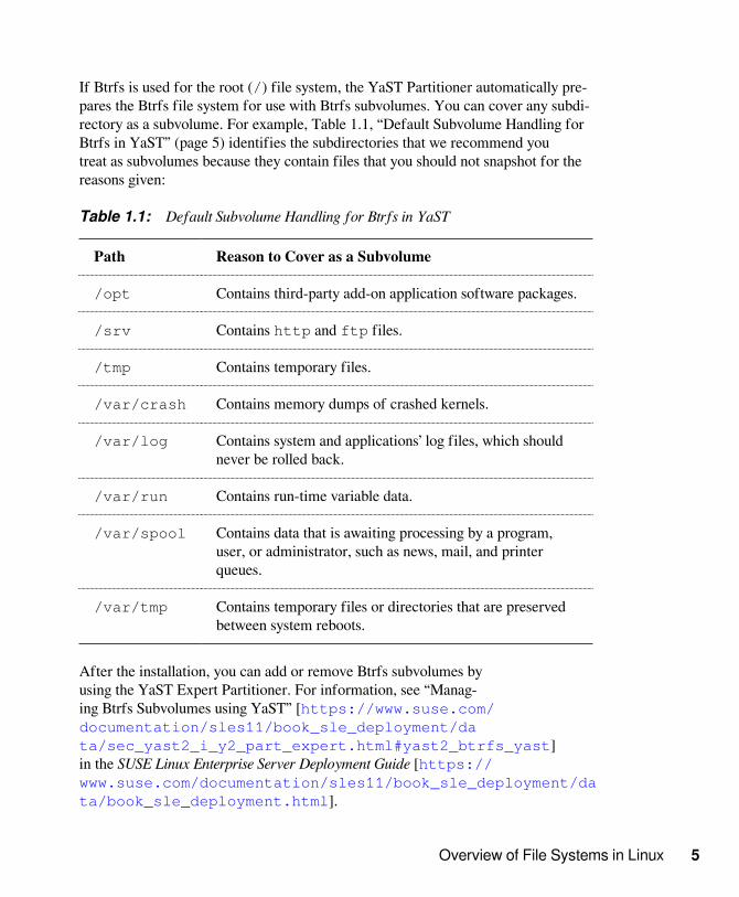
If Btrfs is used for the root (/) file system, the YaST Partitioner automatically pre-pares the Btrfs file system for use with Btrfs subvolumes. You can cover any subdi-rectory as a subvolume. For example, Table 1.1, “Default Subvolume Handling forBtrfs in YaST” (page 5) identifies the subdirectories that we recommend youtreat as subvolumes because they contain files that you should not snapshot for thereasons given:
Table 1.1: Default Subvolume Handling for Btrfs in YaST
Path Reason to Cover as a Subvolume
/opt Contains third-party add-on application software packages.
/srv Contains http and ftp files.
/tmp Contains temporary files.
/var/crash Contains memory dumps of crashed kernels.
/var/log Contains system and applications’ log files, which shouldnever be rolled back.
/var/run Contains run-time variable data.
/var/spool Contains data that is awaiting processing by a program,user, or administrator, such as news, mail, and printerqueues.
/var/tmp Contains temporary files or directories that are preservedbetween system reboots.
After the installation, you can add or remove Btrfs subvolumes byusing the YaST Expert Partitioner. For information, see “Manag-ing Btrfs Subvolumes using YaST” [https://www.suse.com/documentation/sles11/book_sle_deployment/data/sec_yast2_i_y2_part_expert.html#yast2_btrfs_yast]in the SUSE Linux Enterprise Server Deployment Guide [https://www.suse.com/documentation/sles11/book_sle_deployment/data/book_sle_deployment.html].

6 Storage Administration Guide
1.2.1.4 Snapshots for the Root File SystemBtrfs provides writable snapshots with the SUSE Snapper infrastructure that allow youto easily roll back your system if needed after applying updates, or to back up files.Snapper allows you to create and delete snapshots, and to compare snapshots and re-vert the differences between them. If Btrfs is used for the root (/) file system, YaSTautomatically enables snapshots for the root file system.
For information about Snapper and its integration in ZYpp (snapper-zypp-plugin) and YaST (yast2-snapper), see “Snapshots/Rollback with Snapper”[http://www.suse.com/documentation/sles11/book_sle_admin/data/cha_snapper.html] in the SSUSE Linux Enterprise Server Admin-istration Guide [http://www.suse.com/documentation/sles11/book_sle_admin/data/book_sle_admin.html].
To prevent snapshots from filling up the system disk, you can change the Snap-per cleanup defaults to be more aggressive in the /etc/snapper/configs/root configuration file, or for other mount points. Snapper pro-vides three algorithms to clean up old snapshots that are executed in a dai-ly cron-job. The cleanup frequency is defined in the Snapper configura-tion for the mount point. Lower the TIMELINE_LIMIT parameters for dai-ly, monthly, and yearly to reduce how long and the number of snapshots tobe retained. For information, see “Adjusting the Config File” [https://www.suse.com/documentation/sles11/book_sle_admin/data/sec_snapper_config.html#sec_snapper_config_modify]in the SUSE Linux Enterprise Server Administration Guide [https://www.suse.com/documentation/sles11/book_sle_admin/data/book_sle_admin.html].
For information about the SUSE Snapper project, see the Snapper Portal wiki atOpenSUSE.org [http://en.opensuse.org/Portal:Snapper].
1.2.1.5 Online Check and Repair FunctionalityThe scrub check and repair functionality is available as part of the Btrfs commandline tools. It verifies the integrity of data and metadata, assuming the tree structuresis fine. You can run scrub periodically on a mounted file system; it runs as a back-ground process during normal operation.
Overview of File Systems in Linux 7
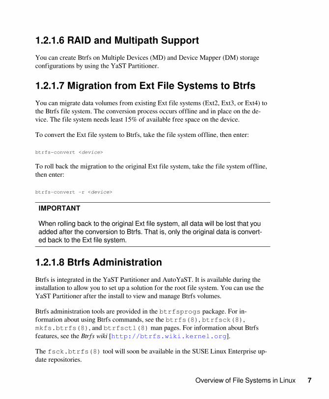
1.2.1.6 RAID and Multipath SupportYou can create Btrfs on Multiple Devices (MD) and Device Mapper (DM) storageconfigurations by using the YaST Partitioner.
1.2.1.7 Migration from Ext File Systems to BtrfsYou can migrate data volumes from existing Ext file systems (Ext2, Ext3, or Ext4) tothe Btrfs file system. The conversion process occurs offline and in place on the de-vice. The file system needs least 15% of available free space on the device.
To convert the Ext file system to Btrfs, take the file system offline, then enter:
btrfs-convert <device>
To roll back the migration to the original Ext file system, take the file system offline,then enter:
btrfs-convert -r <device>
IMPORTANT
When rolling back to the original Ext file system, all data will be lost that youadded after the conversion to Btrfs. That is, only the original data is convert-ed back to the Ext file system.
1.2.1.8 Btrfs AdministrationBtrfs is integrated in the YaST Partitioner and AutoYaST. It is available during theinstallation to allow you to set up a solution for the root file system. You can use theYaST Partitioner after the install to view and manage Btrfs volumes.
Btrfs administration tools are provided in the btrfsprogs package. For in-formation about using Btrfs commands, see the btrfs(8), btrfsck(8),mkfs.btrfs(8), and btrfsctl(8) man pages. For information about Btrfsfeatures, see the Btrfs wiki [http://btrfs.wiki.kernel.org].
The fsck.btrfs(8) tool will soon be available in the SUSE Linux Enterprise up-date repositories.

8 Storage Administration Guide
1.2.1.9 Btrfs Quota Support for SubvolumesThe Btrfs root file system subvolumes /var/log, /var/crash and /var/cache can use all of the available disk space during normal operation, and cause asystem malfunction. To help avoid this situation, SUSE Linux Enterprise now offersBtrfs quota support for subvolumes. See the btrfs(8) manual page for more de-tails.
1.2.2 Ext2The origins of Ext2 go back to the early days of Linux history. Its predecessor, theExtended File System, was implemented in April 1992 and integrated in Linux 0.96c.The Extended File System underwent a number of modifications and, as Ext2, be-came the most popular Linux file system for years. With the creation of journalingfile systems and their short recovery times, Ext2 became less important.
A brief summary of Ext2’s strengths might help understand why it was—and in someareas still is—the favorite Linux file system of many Linux users.
• Section 1.2.2.1, “Solidity and Speed” (page 8)
• Section 1.2.2.2, “Easy Upgradability” (page 9)
1.2.2.1 Solidity and SpeedBeing quite an “old-timer,” Ext2 underwent many improvements and was heavily test-ed. This might be the reason why people often refer to it as rock-solid. After a systemoutage when the file system could not be cleanly unmounted, e2fsck starts to analyzethe file system data. Metadata is brought into a consistent state and pending files ordata blocks are written to a designated directory (called lost+found). In contrast tojournaling file systems, e2fsck analyzes the entire file system and not just the recent-ly modified bits of metadata. This takes significantly longer than checking the log da-ta of a journaling file system. Depending on file system size, this procedure can takehalf an hour or more. Therefore, it is not desirable to choose Ext2 for any server thatneeds high availability. However, because Ext2 does not maintain a journal and usessignificantly less memory, it is sometimes faster than other file systems.

Overview of File Systems in Linux 9
1.2.2.2 Easy UpgradabilityBecause Ext3 is based on the Ext2 code and shares its on-disk format as well as itsmetadata format, upgrades from Ext2 to Ext3 are very easy.
1.2.3 Ext3Ext3 was designed by Stephen Tweedie. Unlike all other next-generation file systems,Ext3 does not follow a completely new design principle. It is based on Ext2. Thesetwo file systems are very closely related to each other. An Ext3 file system can be eas-ily built on top of an Ext2 file system. The most important difference between Ext2and Ext3 is that Ext3 supports journaling. In summary, Ext3 has three major advan-tages to offer:
• Section 1.2.3.1, “Easy and Highly Reliable Upgrades from Ext2” (page 9)
• Section 1.2.3.2, “Reliability and Performance” (page 10)
• Section 1.2.3.3, “Converting an Ext2 File System into Ext3” (page 10)
• Section 1.2.3.4, “Ext3 File System Inode Size and Number of Inodes” (page 11)
1.2.3.1 Easy and Highly Reliable Upgrades fromExt2The code for Ext2 is the strong foundation on which Ext3 could become a highly-ac-claimed next-generation file system. Its reliability and solidity are elegantly combinedin Ext3 with the advantages of a journaling file system. Unlike transitions to otherjournaling file systems, such as ReiserFS or XFS, which can be quite tedious (makingbackups of the entire file system and recreating it from scratch), a transition to Ext3 isa matter of minutes. It is also very safe, because re-creating an entire file system fromscratch might not work flawlessly. Considering the number of existing Ext2 systemsthat await an upgrade to a journaling file system, you can easily see why Ext3 mightbe of some importance to many system administrators. Downgrading from Ext3 toExt2 is as easy as the upgrade. Just perform a clean unmount of the Ext3 file systemand remount it as an Ext2 file system.
10 Storage Administration Guide
1.2.3.2 Reliability and PerformanceSome other journaling file systems follow the “metadata-only” journaling approach.This means your metadata is always kept in a consistent state, but this cannot be au-tomatically guaranteed for the file system data itself. Ext3 is designed to take care ofboth metadata and data. The degree of “care” can be customized. Enabling Ext3 inthe data=journal mode offers maximum security (data integrity), but can slowdown the system because both metadata and data are journaled. A relatively new ap-proach is to use the data=ordered mode, which ensures both data and metadataintegrity, but uses journaling only for metadata. The file system driver collects all datablocks that correspond to one metadata update. These data blocks are written to diskbefore the metadata is updated. As a result, consistency is achieved for metadata anddata without sacrificing performance. A third option to use is data=writeback,which allows data to be written into the main file system after its metadata has beencommitted to the journal. This option is often considered the best in performance. Itcan, however, allow old data to reappear in files after crash and recovery while inter-nal file system integrity is maintained. Ext3 uses the data=ordered option as thedefault.
1.2.3.3 Converting an Ext2 File System into Ext3To convert an Ext2 file system to Ext3:
1 Create an Ext3 journal by running tune2fs -j as the root user.
This creates an Ext3 journal with the default parameters.
To specify how large the journal should be and on which device it should reside,run tune2fs -J instead together with the desired journal options size= anddevice=. More information about the tune2fs program is available in thetune2fs man page.
2 Edit the file /etc/fstab as the root user to change the file system type speci-fied for the corresponding partition from ext2 to ext3, then save the changes.
This ensures that the Ext3 file system is recognized as such. The change takes ef-fect after the next reboot.
3 To boot a root file system that is set up as an Ext3 partition, include the modulesext3 and jbd in the initrd.

Overview of File Systems in Linux 11
3a Edit /etc/sysconfig/kernel as root, adding ext3 and jbd to theINITRD_MODULES variable, then save the changes.
3b Run the mkinitrd command.
This builds a new initrd and prepares it for use.
4 Reboot the system.
1.2.3.4 Ext3 File System Inode Size and Numberof InodesAn inode stores information about the file and its block location in the file system. Toallow space in the inode for extended attributes and ACLs, the default inode size forExt3 was increased from 128 bytes on SLES 10 to 256 bytes on SLES 11. As com-pared to SLES 10, when you make a new Ext3 file system on SLES 11, the defaultamount of space pre-allocated for the same number of inodes is doubled, and the us-able space for files in the file system is reduced by that amount. Thus, you must uselarger partitions to accommodate the same number of inodes and files than were pos-sible for an Ext3 file system on SLES 10.
When you create a new Ext3 file system, the space in the inode table is pre-allocatedfor the total number of inodes that can be created. The bytes-per-inode ratio and thesize of the file system determine how many inodes are possible. When the file systemis made, an inode is created for every bytes-per-inode bytes of space:
number of inodes = total size of the file system divided by the number of bytes per inode
The number of inodes controls the number of files you can have in the file system:one inode for each file. To address the increased inode size and reduced usable spaceavailable, the default for the bytes-per-inode ratio was increased from 8192 bytes onSLES 10 to 16384 bytes on SLES 11. The doubled ratio means that the number offiles that can be created is one-half of the number of files possible for an Ext3 filesystem on SLES 10.
IMPORTANT
After the inodes are allocated, you cannot change the settings for the inodesize or bytes-per-inode ratio. No new inodes are possible without recreatingthe file system with different settings, or unless the file system gets extended.

12 Storage Administration Guide
When you exceed the maximum number of inodes, no new files can be creat-ed on the file system until some files are deleted.
When you make a new Ext3 file system, you can specify the inode size and bytes-per-inode ratio to control inode space usage and the number of files possible on the filesystem. If the blocks size, inode size, and bytes-per-inode ratio values are not speci-fied, the default values in the /etc/mked2fs.conf file are applied. For informa-tion, see the mke2fs.conf(5) man page.
Use the following guidelines:
• Inode size: The default inode size is 256 bytes. Specify a value in bytes that is apower of 2 and equal to 128 or larger in bytes and up to the block size, such as 128,256, 512, and so on. Use 128 bytes only if you do not use extended attributes orACLs on your Ext3 file systems.
• Bytes-per-inode ratio: The default bytes-per-inode ratio is 16384 bytes. Validbytes-per-inode ratio values must be a power of 2 equal to 1024 or greater in bytes,such as 1024, 2048, 4096, 8192, 16384, 32768, and so on. This value should not besmaller than the block size of the file system, because the block size is the smallestchunk of space used to store data. The default block size for the Ext3 file system is4 KB.
In addition, you should consider the number of files and the size of files you needto store. For example, if your file system will have many small files, you can spec-ify a smaller bytes-per-inode ratio, which increases the number of inodes. If yourfile system will have a very large files, you can specify a larger bytes-per-inode ra-tio, which reduces the number of possible inodes.
Generally, it is better to have too many inodes than to run out of them. If you havetoo few inodes and very small files, you could reach the maximum number of fileson a disk that is practically empty. If you have too many inodes and very large files,you might have free space reported but be unable to use it because you cannot cre-ate new files in space reserved for inodes.
If you do not use extended attributes or ACLs on your Ext3 file systems, you can re-store the SLES 10 behavior specifying 128 bytes as the inode size and 8192 bytes asthe bytes-per-inode ratio when you make the file system. Use any of the followingmethods to set the inode size and bytes-per-inode ratio:
• Modifying the default settings for all new Ext3 files: In a text editor,modify the defaults section of the /etc/mke2fs.conf file to set the

Overview of File Systems in Linux 13
inode_size and inode_ratio to the desired default values. The values applyto all new Ext3 file systems. For example:
blocksize = 4096inode_size = 128inode_ratio = 8192
• At the command line: Pass the inode size (-I 128) and the bytes-per-inode ra-tio (-i 8192) to the mkfs.ext3(8) command or the mke2fs(8) commandwhen you create a new Ext3 file system. For example, use either of the followingcommands:
mkfs.ext3 -b 4096 -i 8092 -I 128 /dev/sda2
mke2fs -t ext3 -b 4096 -i 8192 -I 128 /dev/sda2
• During installation with YaST: Pass the inode size and bytes-per-inode ratiovalues when you create a new Ext3 file system during the installation. In the YaSTPartitioner on the Edit Partition page under Formatting Options, select Format parti-tionExt3, then click Options. In the File system options dialog box, select the desiredvalues from the Block Size in Bytes, Bytes-per-inode, and Inode Size drop-down lists.
For example, select 4096 for the Block Size in Bytes drop-down list, select 8192from the Bytes per inode drop-down list, select 128 from the Inode Size drop-downlist, then click OK.

14 Storage Administration Guide
• During installation with autoyast: In an autoyast profile, you can use thefs_options tag to set the opt_bytes_per_inode ratio value of 8192 for -i and the opt_inode_density value of 128 for -I:
<partitioning config:type="list"> <drive> <device>/dev/sda</device> <initialize config:type="boolean">true</initialize> <partitions config:type="list"> <partition> <filesystem config:type="symbol">ext3</filesystem>

Overview of File Systems in Linux 15
<format config:type="boolean">true</format> <fs_options> <opt_bytes_per_inode> <option_str>-i</option_str> <option_value>8192</option_value> </opt_bytes_per_inode> <opt_inode_density> <option_str>-I</option_str> <option_value>128</option_value> </opt_inode_density> </fs_options> <mount>/</mount> <partition_id config:type="integer">131</partition_id> <partition_type>primary</partition_type> <size>25G</size> </partition>
For information, see SLES 11 ext3 partitions can only store 50% of the files thatcan be stored on SLES10 [Technical Information Document 7009075] [http://www.novell.com/support/kb/doc.php?id=7009075].
1.2.4 ReiserFSOfficially one of the key features of the 2.4 kernel release, ReiserFS has been avail-able as a kernel patch for 2.2.x SUSE kernels since version 6.4. ReiserFS was de-signed by Hans Reiser and the Namesys development team. It has proven itself to be apowerful alternative to Ext2. Its key assets are better disk space utilization, better diskaccess performance, faster crash recovery, and reliability through data journaling.
IMPORTANT
The ReiserFS file system is fully supported for the lifetime of SUSE Linux En-terprise Server 11 specifically for migration purposes. SUSE plans to removesupport for creating new ReiserFS file systems starting with SUSE Linux En-terprise Server 12.
• Section 1.2.4.1, “Better Disk Space Utilization” (page 16)
• Section 1.2.4.2, “Better Disk Access Performance” (page 16)
• Section 1.2.4.3, “Fast Crash Recovery” (page 16)
• Section 1.2.4.4, “Reliability through Data Journaling” (page 16)
16 Storage Administration Guide
1.2.4.1 Better Disk Space UtilizationIn ReiserFS, all data is organized in a structure called a B*-balanced tree. The treestructure contributes to better disk space utilization because small files can be storeddirectly in the B* tree leaf nodes instead of being stored elsewhere and just maintain-ing a pointer to the actual disk location. In addition to that, storage is not allocated inchunks of 1 or 4 KB, but in portions of the exact size needed. Another benefit lies inthe dynamic allocation of inodes. This keeps the file system more flexible than tradi-tional file systems, like Ext2, where the inode density must be specified at file systemcreation time.
1.2.4.2 Better Disk Access PerformanceFor small files, file data and “stat_data” (inode) information are often stored next toeach other. They can be read with a single disk I/O operation, meaning that only oneaccess to disk is required to retrieve all the information needed.
1.2.4.3 Fast Crash RecoveryUsing a journal to keep track of recent metadata changes makes a file system check amatter of seconds, even for huge file systems.
1.2.4.4 Reliability through Data JournalingReiserFS also supports data journaling and ordered data modes similar to theconcepts outlined in Section 1.2.3, “Ext3” (page 9). The default mode isdata=ordered, which ensures both data and metadata integrity, but uses journal-ing only for metadata.
1.2.5 XFSOriginally intended as the file system for their IRIX OS, SGI started XFS develop-ment in the early 1990s. The idea behind XFS was to create a high-performance 64-bit journaling file system to meet extreme computing challenges. XFS is very good atmanipulating large files and performs well on high-end hardware. However, even XFShas a drawback. Like ReiserFS, XFS takes great care of metadata integrity, but lesscare of data integrity.

Overview of File Systems in Linux 17
A quick review of XFS’s key features explains why it might prove to be a strong com-petitor for other journaling file systems in high-end computing.
• Section 1.2.5.1, “High Scalability through the Use of Allocation Groups” (page 17)
• Section 1.2.5.2, “High Performance through Efficient Management of Disk Space” (page 17)
• Section 1.2.5.3, “Preallocation to Avoid File System Fragmentation” (page 18)
1.2.5.1 High Scalability through the Use ofAllocation GroupsAt the creation time of an XFS file system, the block device underlying the file sys-tem is divided into eight or more linear regions of equal size. Those are referred to asallocation groups. Each allocation group manages its own inodes and free disk space.Practically, allocation groups can be seen as file systems in a file system. Because al-location groups are rather independent of each other, more than one of them can beaddressed by the kernel simultaneously. This feature is the key to XFS’s great scalabil-ity. Naturally, the concept of independent allocation groups suits the needs of multi-processor systems.
1.2.5.2 High Performance through EfficientManagement of Disk SpaceFree space and inodes are handled by B+ trees inside the allocation groups. The useof B+ trees greatly contributes to XFS’s performance and scalability. XFS uses de-layed allocation, which handles allocation by breaking the process into two pieces.A pending transaction is stored in RAM and the appropriate amount of space is re-served. XFS still does not decide where exactly (in file system blocks) the data shouldbe stored. This decision is delayed until the last possible moment. Some short-livedtemporary data might never make its way to disk, because it is obsolete by the timeXFS decides where actually to save it. In this way, XFS increases write performanceand reduces file system fragmentation. Because delayed allocation results in less fre-quent write events than in other file systems, it is likely that data loss after a crashduring a write is more severe.

18 Storage Administration Guide
1.2.5.3 Preallocation to Avoid File SystemFragmentationBefore writing the data to the file system, XFS reserves (preallocates) the free spaceneeded for a file. Thus, file system fragmentation is greatly reduced. Performance isincreased because the contents of a file are not distributed all over the file system.
1.2.6 File System Feature ComparisonFor a side-by-side feature comparison of the major operating systems in SUSE LinuxEnterprise Server, see File System Support and Sizes [http://www.suse.com/products/server/technical-information/#FileSystem] onthe SUSE Linux Enterprise Server Technical Information Web site [http://www.suse.com/products/server/technical-information/].
1.3 Other Supported File SystemsTable 1.2, “File System Types in Linux” (page 18) summarizes some other filesystems supported by Linux. They are supported mainly to ensure compatibility andinterchange of data with different kinds of media or foreign operating systems.
Table 1.2: File System Types in Linux
File SystemType
Description
cramfs Compressed ROM file system: A compressed read-onlyfile system for ROMs.
hpfs High Performance File System: The IBM OS/2 standardfile system. Only supported in read-only mode.
iso9660 Standard file system on CD-ROMs.
minix This file system originated from academic projects on op-erating systems and was the first file system used in Linux.Today, it is used as a file system for floppy disks.

Overview of File Systems in Linux 19
File SystemType
Description
msdos fat, the file system originally used by DOS, is today usedby various operating systems.
nfs Network File System: Here, data can be stored on any ma-chine in a network and access might be granted via a net-work.
ntfs Windows NT file system; read-only.
smbfs Server Message Block is used by products such as Win-dows to enable file access over a network.
sysv Used on SCO UNIX, Xenix, and Coherent (commercialUNIX systems for PCs).
ufs Used by BSD, SunOS, and NextStep. Only supported inread-only mode.
umsdos UNIX on MS-DOS: Applied on top of a standard fat filesystem, achieves UNIX functionality (permissions, links,long filenames) by creating special files.
vfat Virtual FAT: Extension of the fat file system (supportslong filenames).
1.4 Large File Support in LinuxOriginally, Linux supported a maximum file size of 2 GiB (231 bytes). Unless a filesystem comes with large file support, the maximum file size on a 32-bit system is 2GiB.
Currently, all of our standard file systems have LFS (large file support), which givesa maximum file size of 263 bytes in theory. Table 1.3, “Maximum Sizes of Files andFile Systems (On-Disk Format, 4 KiB Block Size)” (page 20) offers an overviewof the current on-disk format limitations of Linux files and file systems. The numbers

20 Storage Administration Guide
in the table assume that the file systems are using 4 KiB block size, which is a com-mon standard. When using different block sizes, the results are different. The max-imum file sizes in Table 1.3, “Maximum Sizes of Files and File Systems (On-DiskFormat, 4 KiB Block Size)” (page 20) can be larger than the file system's actualsize when using sparse blocks.
NOTE
In this document: 1024 Bytes = 1 KiB; 1024 KiB = 1 MiB; 1024 MiB = 1 GiB;1024 GiB = 1 TiB; 1024 TiB = 1 PiB; 1024 PiB = 1 EiB (see also NIST: Pre-fixes for Binary Multiples [http://physics.nist.gov/cuu/Units/binary.html].
Table 1.3: Maximum Sizes of Files and File Systems (On-Disk Format, 4 KiB BlockSize)
File System (4 KiBBlock Size)
Maximum File Sys-tem Size
Maximum File Size
Btrfs 16 EiB 16 EiB
Ext3 16 TiB 2 TiB
OCFS2 (a clus-ter-aware file systemavailable in the HighAvailability Extension)
16 TiB 1 EiB
ReiserFS v3.6 16 TiB 1 EiB
XFS 8 EiB 8 EiB
NFSv2 (client side) 8 EiB 2 GiB
NFSv3 (client side) 8 EiB 8 EiB
IMPORTANT
Table 1.3, “Maximum Sizes of Files and File Systems (On-Disk Format, 4KiB Block Size)” (page 20) describes the limitations regarding the on-disk

Overview of File Systems in Linux 21
format. The Linux kernel imposes its own limits on the size of files and filesystems handled by it. These are as follows:
File SizeOn 32-bit systems, files cannot exceed 2 TiB (241 bytes).
File System SizeFile systems can be up to 273 bytes in size. However, this limit is still outof reach for the currently available hardware.
1.5 Linux Kernel StorageLimitationsTable 1.4, “Storage Limitations” (page 21) summarizes the kernel limits for stor-age associated with SUSE Linux Enterprise 11 Service Pack 3.
Table 1.4: Storage Limitations
Storage Feature Limitation
Maximum number of LUNs sup-ported
16384 LUNs per target.
Maximum number of paths per sin-gle LUN
No limit per se. Each path is treatedas a normal LUN.
The actual limit is given by the num-ber of LUNs per target and the num-ber of targets per HBA (16777215for a Fibre Channel HBA).
Maximum number of HBAs Unlimited. The actual limit is deter-mined by the amount of PCI slots ofthe system.
Maximum number of paths with de-vice-mapper-multipath (in total) peroperating system
Approximately1024. The actualnumber depends on the length ofthe device number strings. It is a

22 Storage Administration Guide
Storage Feature Limitation
compile-time variable within mul-tipath-tools, which can be raised ifthis limit poses to be a problem.
Maximum size per block device For X86, up to 16 TiB.
For x86_64, ia64, s390x, and ppc64,up to 8 EiB.
1.6 Managing Devices with theYaST PartitionerYou can use the YaST Partitioner to create and manage file systems andRAID devices. For information, see “Advanced Disk Setup” [http://www.suse.com/documentation/sles11/book_sle_deployment/data/cha_advdisk.html] in the SUSE Linux Enterprise Server 11 SP4 De-ployment Guide [https://www.suse.com/documentation/sles11/book_sle_deployment/data/book_sle_deployment.html].
1.7 Additional InformationEach of the file system projects described above maintains its own home page onwhich to find mailing list information, further documentation, and FAQs:
• E2fsprogs: Ext2/3/4 File System Utilities [ http://e2fsprogs.sourceforge.net/ ]
• Introducing Ext3 [ http://www.ibm.com/developerworks/linux/library/l-fs7/ ]
• XFS: A High-Performance Journaling Filesytem [ http://oss.sgi.com/projects/xfs/ ]
• OCFS2 Project [ http://oss.oracle.com/projects/ocfs2/ ]

Overview of File Systems in Linux 23
A comprehensive multipart tutorial about Linux file systems can be found at IB-M developerWorks in the Advanced File System Implementor’s Guide [https://www.ibm.com/developerworks/linux/library/l-fs/].
An in-depth comparison of file systems (not only Linux filesystems) is available from the Wikipedia project in Compari-son of File Systems [http://en.wikipedia.org/wiki/Comparison_of_file_systems#Comparison].
1.7.1 Freeing Unused Filesystem BlocksOn solid state drives (SSDs) and thinly provisioned volumes it is useful to trim blocksnot in use by the file system. SUSE Linux Enterprise Server fully supports unmap ortrim operations on all file systems supporting these methods.
The recommended way to trim a supported file system on SUSE Linux EnterpriseServer is to run /sbin/wiper.sh. Make sure to read /usr/share/doc/packages/hdparm/README.wiper before running this script. For most desk-top and server systems the sufficient trimming frequency is once a week. Mounting afile system with -o discard comes with a performance penalty and may negative-ly affect the lifetime of SSDs and is not recommended.


What’s New for Storage in SLES 11 25
What’s New for Storage inSLES 11 2The features and behavior changes noted in this section were made for SUSE LinuxEnterprise Server 11.
• Section 2.1, “What’s New in SLES 11 SP4” (page 25)
• Section 2.2, “What’s New in SLES 11 SP3” (page 25)
• Section 2.3, “What’s New in SLES 11 SP2” (page 30)
• Section 2.4, “What’s New in SLES 11 SP1” (page 31)
• Section 2.5, “What’s New in SLES 11” (page 35)
2.1 What’s New in SLES 11 SP4In regards of storage, SUSE Linux Enterprise Server SP4 is a bugfix release, no newfeatures were added.
2.2 What’s New in SLES 11 SP3In addition to bug fixes, the features and behavior changes in this section were madefor the SUSE Linux Enterprise Server 11 SP3 release:
• Section 2.2.1, “Btrfs Quotas” (page 26)

26 Storage Administration Guide
• Section 2.2.2, “iSCSI LIO Target Server” (page 26)
• Section 2.2.3, “Linux Software RAIDs” (page 26)
• Section 2.2.4, “LVM2” (page 27)
• Section 2.2.5, “Multipath I/O” (page 27)
2.2.1 Btrfs QuotasBtrfs quota support for subvolumes on the root file system has been added in thebtrfs(8) command.
2.2.2 iSCSI LIO Target ServerYaST supports the iSCSI LIO Target Server software. For information, see Chap-ter 15, Mass Storage over IP Networks: iSCSI LIO Target Server (page 287).
2.2.3 Linux Software RAIDsThe following enhancements were added for Linux software RAIDs:
• Section 2.2.3.1, “Support for Intel RSTe+” (page 26)
• Section 2.2.3.2, “LEDMON Utility” (page 26)
• Section 2.2.3.3, “Device Order in the Software RAID” (page 27)
2.2.3.1 Support for Intel RSTe+The software RAID provides improved support on the Intel RSTe+ (Rapid StorageTechnology Enterprise) platform to support RAID level 0, 1, 4, 5, 6, and 10.
2.2.3.2 LEDMON UtilityThe LEDMON utility supports PCIe-SSD enclosure LEDs for MD software RAIDs.For information, see Chapter 12, Storage Enclosure LED Utilities for MD SoftwareRAIDs (page 235).

What’s New for Storage in SLES 11 27
2.2.3.3 Device Order in the Software RAIDIn the Add RAID wizard in the YaST Partitioner, the Classify option allows you tospecify the order in which the selected devices in a Linux software RAID will be usedto ensure that one half of the array resides on one disk subsystem and the other halfof the array resides on a different disk subsystem. For example, if one disk subsystemfails, the system keeps running from the second disk subsystem. For information, seeStep 4d (page 213) in Section 10.3.3, “Creating a Complex RAID10 with the YaSTPartitioner” (page 212).
2.2.4 LVM2The following enhancements were added for LVM2:
• Section 2.2.4.1, “Thin Pool and Thin Volumes” (page 27)
• Section 2.2.4.2, “Thin Snapshots” (page 27)
2.2.4.1 Thin Pool and Thin VolumesLVM logical volumes can be thinly provisioned. For information, see Section 4.5,“Configuring Logical Volumes” (page 56).
• Thin pool: The logical volume is a pool of space that is reserved for use with thinvolumes. The thin volumes can allocate their needed space from it on demand.
• Thin volume: The volume is created as a sparse volume. The volume allocatesneeded space on demand from a thin pool.
2.2.4.2 Thin SnapshotsLVM logical volume snapshots can be thinly provisioned. Thin provisioning is as-sumed if you to create a snapshot without a specified size. For information, see Sec-tion 17.2, “Creating Linux Snapshots with LVM” (page 341).
2.2.5 Multipath I/OThe following changes and enhancements were made for multipath I/O:
• Section 2.2.5.1, “mpathpersist(8)” (page 28)

28 Storage Administration Guide
• Section 2.2.5.2, “multipath(8)” (page 28)
• Section 2.2.5.3, “/etc/multipath.conf” (page 28)
2.2.5.1 mpathpersist(8)The mpathpersist(8) utility is new. It can be used to manage SCSI persistentreservations on Device Mapper Multipath devices. For information, see Section 7.3.5,“Linux mpathpersist(8) Utility” (page 123).
2.2.5.2 multipath(8)The following enhancement was added to the multipath(8) command:
• The -r option allows you to force a device map reload.
2.2.5.3 /etc/multipath.confThe Device Mapper - Multipath tool added the following enhancements for the /etc/multipath.conf file:
• udev_dir
The udev_dir attribute is deprecated. After you upgrade to SLES 11 SP3 or alater version, you can remove the following line from the defaults section ofyour /etc/multipath.conf file:
udev_dir /dev
• getuid_callout
In the defaults section of the /etc/multipath.conf file,the getuid_callout attribute is deprecated and replaced by theuid_attribute parameter. This parameter is a udev attribute that provides aunique path identifier. The default value is ID_SERIAL.
After you upgrade to SLES 11 SP3 or a later version, you can modify the attributesin the defaults section of your /etc/multipath.conf file:
• Remove the following line from the defaults section:

What’s New for Storage in SLES 11 29
getuid_callout "/lib/udev/scsi_id --whitelisted --device=/dev/%n"
• Add the following line to the defaults section:
uid_attribute "ID_SERIAL"
• path_selector
In the defaults section of the /etc/multipath.conf file, the default val-ue for the path_selector attribute was changed from "round-robin 0"to "service-time 0". The service-time option chooses the path for thenext bunch of I/O based on the amount of outstanding I/O to the path and its rela-tive throughput.
After you upgrade to SLES 11 SP3 or a later version, you can modify the attributevalue in the defaults section of your /etc/multipath.conf file to use therecommended default:
path_selector "service-time 0"
• user_friendly_names
The user_friendly_names attribute can be configured in the devices sec-tion and in the multipaths section.
• max_fds
The default setting for the max_fds attribute was changed to max. This allows themultipath daemon to open as many file descriptors as the system allows when it ismonitoring paths.
After you upgrade to SLES 11 SP3 or a later version, you can modify the attributevalue in your /etc/multipath.conf file:
max_fds "max"
• reservation_key
In the defaults section or multipaths section of the /etc/multipath.conf file, the reservation_key attribute can be used to assigna Service Action Reservation Key that is used with the mpathpersist(8) util-ity to manage persistent reservations for Device Mapper Multipath devices. The at-

30 Storage Administration Guide
tribute is not used by default. If it is not set, the multipathd daemon does notcheck for persistent reservation for newly discovered paths or reinstated paths.
reservation_key <reservation key>
For example:
multipaths { multipath { wwid XXXXXXXXXXXXXXXX alias yellow reservation_key 0x123abc }}
For information about setting persistent reservations, see Section 7.3.5, “Linuxmpathpersist(8) Utility” (page 123).
• hardware_handler
Four SCSI hardware handlers were added in the SCSI layer that can be used withDM-Multipath:
scsi_dh_aluascsi_dh_rdacscsi_dh_hp_swscsi_dh_emc
These handlers are modules created under the SCSI directory in the Linux kernel.Previously, the hardware handler in the Device Mapper layer was used.
Add the modules to the initrd image, then specify them in the /etc/multipath.conf file as hardware handler types alua, rdac, hp_sw, andemc. For information about adding the device drivers to the initrd image,see Section 7.4.3, “Configuring the Device Drivers in initrd for Multipathing” (page 128).
2.3 What’s New in SLES 11 SP2In addition to bug fixes, the features and behavior changes in this section were madefor the SUSE Linux Enterprise Server 11 SP2 release:

What’s New for Storage in SLES 11 31
• Btrfs File System. See Section 1.2.1, “Btrfs” (page 3).
• Open Fibre Channel over Ethernet. See Chapter 16, Fibre Channel Storage overEthernet Networks: FCoE (page 321).
• Tagging for LVM storage objects. See Section 4.7, “Tagging LVM2 StorageObjects” (page 61).
• NFSv4 ACLs tools. See Chapter 18, Managing Access Control Lists overNFSv4 (page 349).
• --assume-clean option for mdadm resize command. See Section 11.2.2,“Increasing the Size of the RAID Array” (page 224).
• In the defaults section of the /etc/multipath.conf file,the default_getuid parameter was obsoleted and replaced by thegetuid_callout parameter:
The line changed from this:
default_getuid "/sbin/scsi_id -g -u -s /block/%n"
to this:
getuid_callout "/lib/udev/scsi_id --whitelisted --device=/dev/%n"
2.4 What’s New in SLES 11 SP1In addition to bug fixes, the features and behavior changes noted in this section weremade for the SUSE Linux Enterprise Server 11 SP1 release.
• Section 2.4.1, “Saving iSCSI Target Information” (page 32)
• Section 2.4.2, “Modifying Authentication Parameters in the iSCSI Initiator” (page 32)
• Section 2.4.3, “ Allowing Persistent Reservations for MPIO Devices” (page 32)
• Section 2.4.4, “MDADM 3.0.2” (page 33)

32 Storage Administration Guide
• Section 2.4.5, “Boot Loader Support for MDRAID External Metadata” (page 33)
• Section 2.4.6, “YaST Install and Boot Support for MDRAID External Metadata” (page 33)
• Section 2.4.7, “Improved Shutdown for MDRAID Arrays that Contain the RootFile System” (page 34)
• Section 2.4.8, “MD over iSCSI Devices” (page 34)
• Section 2.4.9, “MD-SGPIO” (page 34)
• Section 2.4.10, “Resizing LVM 2 Mirrors ” (page 35)
• Section 2.4.11, “Updating Storage Drivers for Adapters on IBM Servers” (page 35)
2.4.1 Saving iSCSI Target InformationIn the YaSTNetwork ServicesiSCSI Target function, a Save option was added that al-lows you to export the iSCSI target information. This makes it easier to provide infor-mation to consumers of the resources.
2.4.2 Modifying AuthenticationParameters in the iSCSI InitiatorIn the YaSTNetwork ServicesiSCSI Initiator function, you can modify the authentica-tion parameters for connecting to a target devices. Previously, you needed to deletethe entry and re-create it in order to change the authentication information.
2.4.3 Allowing Persistent Reservationsfor MPIO DevicesA SCSI initiator can issue SCSI reservations for a shared storage device, which locksout SCSI initiators on other servers from accessing the device. These reservationspersist across SCSI resets that might happen as part of the SCSI exception handlingprocess.

What’s New for Storage in SLES 11 33
The following are possible scenarios where SCSI reservations would be useful:
• In a simple SAN environment, persistent SCSI reservations help protect against ad-ministrator errors where a LUN is attempted to be added to one server but it is al-ready in use by another server, which might result in data corruption. SAN zoningis typically used to prevent this type of error.
• In a high-availability environment with failover set up, persistent SCSI reservationshelp protect against errant servers connecting to SCSI devices that are reserved byother servers.
2.4.4 MDADM 3.0.2Use the latest version of the Multiple Devices Administration (MDADM, mdadm)utility to take advantage of bug fixes and improvements.
2.4.5 Boot Loader Support for MDRAIDExternal MetadataSupport was added to use the external metadata capabilities of the MDADM utilityversion 3.0 to install and run the operating system from RAID volumes defined by theIntel Matrix Storage Technology metadata format. This moves the functionality fromthe Device Mapper RAID (DMRAID) infrastructure to the Multiple Devices RAID(MDRAID) infrastructure, which offers the more mature RAID 5 implementationand offers a wider feature set of the MD kernel infrastructure. It allows a commonRAID driver to be used across all metadata formats, including Intel, DDF (commonRAID disk data format), and native MD metadata.
2.4.6 YaST Install and Boot Support forMDRAID External MetadataThe YaST installer tool added support for MDRAID External Metadata for RAID 0,1, 10, 5, and 6. The installer can detect RAID arrays and whether the platform RAIDcapabilities are enabled. If multipath RAID is enabled in the platform BIOS for IntelMatrix Storage Manager, it offers options for DMRAID, MDRAID (recommended),

34 Storage Administration Guide
or none. The initrd was also modified to support assembling BIOS-based RAIDarrays.
2.4.7 Improved Shutdown for MDRAIDArrays that Contain the Root File SystemShutdown scripts were modified to wait until all of the MDRAID arrays are markedclean. The operating system shutdown process now waits for a dirty-bit to be cleareduntil all MDRAID volumes have finished write operations.
Changes were made to the startup script, shutdown script, and the initrd to con-sider whether the root (/) file system (the system volume that contains the operatingsystem and application files) resides on a software RAID array. The metadata han-dler for the array is started early in the shutdown process to monitor the final root filesystem environment during the shutdown. The handler is excluded from the generalkillall events. The process also allows for writes to be quiesced and for the array’smetadata dirty-bit (which indicates whether an array needs to be resynchronized) tobe cleared at the end of the shutdown.
2.4.8 MD over iSCSI DevicesThe YaST installer now allows MD to be configured over iSCSI devices.
If RAID arrays are needed on boot, the iSCSI initiator software is loaded beforeboot.md so that the iSCSI targets are available to be auto-configured for the RAID.
For a new install, Libstorage creates an /etc/mdadm.conf file and adds the lineAUTO -all. During an update, the line is not added. If /etc/mdadm.conf con-tains the line
AUTO -all
then no RAID arrays are auto-assembled unless they are explicitly listed in /etc/mdadm.conf.
2.4.9 MD-SGPIOThe MD-SGPIO utility is a standalone application that monitors RAID arrays viasysfs(2). Events trigger an LED change request that controls blinking for LED

What’s New for Storage in SLES 11 35
lights that are associated with each slot in an enclosure or a drive bay of a storage sub-system. It supports two types of LED systems:
• 2-LED systems (Activity LED, Status LED)
• 3-LED systems (Activity LED, Locate LED, Fail LED)
2.4.10 Resizing LVM 2 MirrorsThe lvresize, lvextend, and lvreduce commands that are used to resize log-ical volumes were modified to allow the resizing of LVM 2 mirrors. Previously, thesecommands reported errors if the logical volume was a mirror.
2.4.11 Updating Storage Drivers forAdapters on IBM ServersUpdate the following storage drivers to use the latest available versions to supportstorage adapters on IBM servers:
• Adaptec: aacraid, aic94xx
• Emulex: lpfc
• LSI: mptas, megaraid_sas
The mptsas driver now supports native EEH (Enhanced Error Handler) recovery,which is a key feature for all of the IO devices for Power platform customers.
• qLogic: qla2xxx, qla3xxx, qla4xxx
2.5 What’s New in SLES 11The features and behavior changes noted in this section were made for the SUSE Lin-ux Enterprise Server 11 release.
• Section 2.5.1, “EVMS2 Is Deprecated” (page 36)
• Section 2.5.2, “Ext3 as the Default File System” (page 37)

36 Storage Administration Guide
• Section 2.5.3, “Default Inode Size Increased for Ext3” (page 38)
• Section 2.5.4, “JFS File System Is Deprecated” (page 38)
• Section 2.5.5, “OCFS2 File System Is in the High Availability Release” (page 38)
• Section 2.5.6, “/dev/disk/by-name Is Deprecated” (page 38)
• Section 2.5.7, “Device Name Persistence in the /dev/disk/by-id Directory” (page 38)
• Section 2.5.8, “Filters for Multipathed Devices” (page 39)
• Section 2.5.9, “User-Friendly Names for Multipathed Devices” (page 39)
• Section 2.5.10, “Advanced I/O Load-Balancing Options for Multipath” (page 40)
• Section 2.5.11, “Location Change for Multipath Tool Callouts” (page 40)
• Section 2.5.12, “Change from mpath to multipath for the mkinitrd -f Option” (page 40)
• Section 2.5.13, “Change from Multibus to Failover as the Default Setting for theMPIO Path Grouping Policy” (page 41)
2.5.1 EVMS2 Is DeprecatedThe Enterprise Volume Management Systems (EVMS2) storage management so-lution is deprecated. All EVMS management modules have been removed fromthe SUSE Linux Enterprise Server 11 packages. Your non-system EVMS-manageddevices should be automatically recognized and managed by Linux Volume Man-ager 2 (LVM2) when you upgrade your system. For more information, see Evo-lution of Storage and Volume Management in SUSE Linux Enterprise [http://www.novell.com/linux/volumemanagement/strategy.html].
If you have EVMS managing the system device (any device that contains the root (/),/boot, or swap), try these things to prepare the SLES 10 server before you rebootthe server to upgrade:

What’s New for Storage in SLES 11 37
1 In the /etc/fstab file, modify the boot and swap disks to the default /dev/system/sys_lx directory:
1a Remove /evms/lvm2 from the path for the swap and root (/) partitions.
1b Remove /evms from the path for /boot partition.
2 In the /boot/grub/menu.lst file, remove /evms/lvm2 from the path.
3 In the /etc/sysconfig/bootloader file, verify that the path for the bootdevice is the /dev directory.
4 Ensure that boot.lvm and boot.md are enabled:
4a In YaST, click SystemRunlevel EditorExpert Mode.
4b Select boot.lvm.
4c Click Set/ResetEnable the Service.
4d Select boot.md.
4e Click Set/ResetEnable the Service.
4f Click Finish, then click Yes.
5 Reboot and start the upgrade.
For information about managing storage with EVMS2 on SUSE Linux EnterpriseServer 10, see the SUSE Linux Enterprise Server 10 SP3: Storage Administration Guide[http://www.novell.com/documentation/sles10/stor_admin/data/bookinfo.html].
2.5.2 Ext3 as the Default File SystemThe Ext3 file system has replaced ReiserFS as the default file system recommend-ed by the YaST tools at installation time and when you create file systems. Reis-erFS is still supported. For more information, see File System Support [http://www.novell.com/linux/techspecs.html?tab=2] on the SUSE Linux En-terprise 11 Tech Specs Web page.

38 Storage Administration Guide
2.5.3 Default Inode Size Increased forExt3To allow space for extended attributes and ACLs for a file on Ext3 file systems, thedefault inode size for Ext3 was increased from 128 bytes on SLES 10 to 256 byteson SLES 11. For information, see Section 1.2.3.4, “Ext3 File System Inode Size andNumber of Inodes” (page 11).
2.5.4 JFS File System Is DeprecatedThe JFS file system is no longer supported. The JFS utilities were removed from thedistribution.
2.5.5 OCFS2 File System Is in the HighAvailability ReleaseThe OCFS2 file system is fully supported as part of the SUSE Linux Enterprise HighAvailability Extension.
2.5.6 /dev/disk/by-name Is DeprecatedThe /dev/disk/by-name path is deprecated in SUSE Linux Enterprise Server 11packages.
2.5.7 Device Name Persistence in the /dev/disk/by-id DirectoryIn SUSE Linux Enterprise Server 11, the default multipath setup relies on udev tooverwrite the existing symbolic links in the /dev/disk/by-id directory whenmultipathing is started. Before you start multipathing, the link points to the SCSI de-vice by using its scsi-xxx name. When multipathing is running, the symbolic linkpoints to the device by using its dm-uuid-xxx name. This ensures that the symbol-ic links in the /dev/disk/by-id path persistently point to the same device re-gardless of whether multipathing is started or not. The configuration files (such as

What’s New for Storage in SLES 11 39
lvm.conf and md.conf) do not need to be modified because they automaticallypoint to the correct device.
See the following sections for more information about how this behavior change af-fects other features:
• Section 2.5.8, “Filters for Multipathed Devices” (page 39)
• Section 2.5.9, “User-Friendly Names for Multipathed Devices” (page 39)
2.5.8 Filters for Multipathed DevicesThe deprecation of the /dev/disk/by-name directory (as described in Sec-tion 2.5.6, “/dev/disk/by-name Is Deprecated” (page 38)) affects how you setup filters for multipathed devices in the configuration files. If you used the /dev/disk/by-name device name path for the multipath device filters in the /etc/lvm/lvm.conf file, you need to modify the file to use the /dev/disk/by-idpath. Consider the following when setting up filters that use the by-id path:
• The /dev/disk/by-id/scsi-* device names are persistent and created forexactly this purpose.
• Do not use the /dev/disk/by-id/dm-* name in the filters. These are symbol-ic links to the Device-Mapper devices, and result in reporting duplicate PVs in re-sponse to a pvscan command. The names appear to change from LVM-pvuuidto dm-uuid and back to LVM-pvuuid.
For information about setting up filters, see Section 7.2.4, “Using LVM2 on Multi-path Devices” (page 102).
2.5.9 User-Friendly Names forMultipathed DevicesA change in how multipathed device names are handled in the /dev/disk/by-iddirectory (as described in Section 2.5.7, “Device Name Persistence in the /dev/disk/by-id Directory” (page 38)) affects your setup for user-friendly names becausethe two names for the device differ. You must modify the configuration files to scanonly the device mapper names after multipathing is configured.

40 Storage Administration Guide
For example, you need to modify the lvm.conf file to scan using the multipatheddevice names by specifying the /dev/disk/by-id/dm-uuid-.*-mpath-.*path instead of /dev/disk/by-id.
2.5.10 Advanced I/O Load-BalancingOptions for MultipathThe following advanced I/O load-balancing options are available for Device MapperMultipath, in addition to round-robin:
• Least-pending
• Length-load-balancing
• Service-time
For information, see “path_selector” (page 154) in Section 7.11.2.1, “Understand-ing Priority Groups and Attributes” (page 147).
2.5.11 Location Change for MultipathTool CalloutsThe mpath_* prio_callouts for the Device Mapper Multipath tool have been movedto shared libraries in/lib/libmultipath/lib*. By using shared libraries, thecallouts are loaded into memory on daemon startup. This helps avoid a system dead-lock on an all-paths-down scenario where the programs need to be loaded from thedisk, which might not be available at this point.
2.5.12 Change from mpath to multipathfor the mkinitrd -f OptionThe option for adding Device Mapper Multipath services to the initrd has changedfrom -f mpath to -f multipath.
To make a new initrd, the command is now:

What’s New for Storage in SLES 11 41
mkinitrd -f multipath
2.5.13 Change from Multibus to Failoveras the Default Setting for the MPIO PathGrouping PolicyThe default setting for the path_grouping_policy in the /etc/multipath.conffile has changed from multibus to failover.
For information about configuring the path_grouping_policy, see Section 7.11, “Con-figuring Path Failover Policies and Priorities” (page 145).


Planning a Storage Solution 43
Planning a Storage Solution 3Consider what your storage needs are and how you can effectively manage and divideyour storage space to best meet your needs. Use the information in this section to helpplan your storage deployment for file systems on your SUSE Linux Enterprise Server11 server.
• Section 3.1, “Partitioning Devices” (page 43)
• Section 3.2, “Multipath Support” (page 43)
• Section 3.3, “Software RAID Support” (page 44)
• Section 3.4, “File System Snapshots” (page 44)
• Section 3.5, “Backup and Antivirus Support” (page 44)
3.1 Partitioning DevicesFor information about using the YaST Expert Partitioner, see “Using the YaST Parti-tioner” in the SUSE Linux Enterprise Server 11 Installation and Administration Guide.
3.2 Multipath SupportLinux supports using multiple I/O paths for fault-tolerant connections between theserver and its storage devices. Linux multipath support is disabled by default. If you

44 Storage Administration Guide
use a multipath solution that is provided by your storage subsystem vendor, you do notneed to configure the Linux multipath separately.
3.3 Software RAID SupportLinux supports hardware and software RAID devices. If you use hardware RAID de-vices, software RAID devices are unnecessary. You can use both hardware and soft-ware RAID devices on the same server.
To maximize the performance benefits of software RAID devices, partitions usedfor the RAID should come from different physical devices. For software RAID 1 de-vices, the mirrored partitions cannot share any disks in common.
3.4 File System SnapshotsLinux supports file system snapshots.
3.5 Backup and Antivirus Support• Section 3.5.1, “Open Source Backup” (page 44)
• Section 3.5.2, “Commercial Backup and Antivirus Support” (page 45)
3.5.1 Open Source BackupOpen source tools for backing up data on Linux include tar, cpio, and rsync. Seethe man pages for these tools for more information.
• PAX: POSIX File System Archiver. It supports cpio and tar, which are the twomost common forms of standard archive (backup) files. See the man page for moreinformation.
• Amanda: The Advanced Maryland Automatic Network Disk Archiver. Seewww.amanda.org [http://www.amanda.org/].

Planning a Storage Solution 45
3.5.2 Commercial Backup and AntivirusSupportNovell Open Enterprise Server (OES) 2 for Linux is a product that includes SUSELinux Enterprise Server (SLES) 10. Antivirus and backup software vendors who sup-port OES 2 also support SLES 10. You can visit the vendor Web sites to find outabout their scheduled support of SLES 11.
For a current list of possible backup and antivirus software vendors, see Nov-ell Open Enterprise Server Partner Support: Backup and Antivirus Support[http://www.novell.com/products/openenterpriseserver/partners_communities.html]. This list is updated quarterly.


LVM Configuration 47
LVM Configuration 4This section briefly describes the principles behind Logical Volume Manager (LVM)and its basic features that make it useful under many circumstances. The YaST LVMconfiguration can be reached from the YaST Expert Partitioner. This partitioning toolenables you to edit and delete existing partitions and create new ones that should beused with LVM.
WARNING
Using LVM might be associated with increased risk, such as data loss. Risksalso include application crashes, power failures, and faulty commands. Saveyour data before implementing LVM or reconfiguring volumes. Never workwithout a backup.
• Section 4.1, “Understanding the Logical Volume Manager” (page 48)
• Section 4.2, “Creating LVM Partitions” (page 50)
• Section 4.3, “Creating Volume Groups” (page 52)
• Section 4.4, “Configuring Physical Volumes” (page 54)
• Section 4.5, “Configuring Logical Volumes” (page 56)
• Section 4.6, “Automatically Activating Non-Root LVM Volume Groups” (page 60)
• Section 4.7, “Tagging LVM2 Storage Objects” (page 61)

48 Storage Administration Guide
• Section 4.8, “Resizing a Volume Group” (page 69)
• Section 4.9, “Resizing a Logical Volume with YaST” (page 71)
• Section 4.10, “Resizing a Logical Volume with Commands” (page 72)
• Section 4.11, “Deleting a Volume Group” (page 73)
• Section 4.12, “Deleting an LVM Partition (Physical Volume)” (page 74)
• Section 4.13, “Using LVM Commands” (page 74)
4.1 Understanding the LogicalVolume ManagerLVM enables flexible distribution of hard disk space over several file systems. It wasdeveloped because the need to change the segmentation of hard disk space might ariseonly after the initial partitioning has already been done during installation. Becauseit is difficult to modify partitions on a running system, LVM provides a virtual pool(volume group or VG) of memory space from which logical volumes (LVs) can becreated as needed. The operating system accesses these LVs instead of the physicalpartitions. Volume groups can span more than one disk, so that several disks or partsof them can constitute one single VG. In this way, LVM provides a kind of abstrac-tion from the physical disk space that allows its segmentation to be changed in a mucheasier and safer way than through physical repartitioning.
Figure 4.1, “Physical Partitioning versus LVM” (page 49) compares physical par-titioning (left) with LVM segmentation (right). On the left side, one single disk hasbeen divided into three physical partitions (PART), each with a mount point (MP) as-signed so that the operating system can access them. On the right side, two disks havebeen divided into two and three physical partitions each. Two LVM volume groups(VG 1 and VG 2) have been defined. VG 1 contains two partitions from DISK 1 andone from DISK 2. VG 2 contains the remaining two partitions from DISK 2.

LVM Configuration 49
Figure 4.1: Physical Partitioning versus LVM
PART PART PART PART PART
DISK
PART PART PART
MP MP MP MP MP MP MP
DISK 1 DISK 2
VG 1 VG 2
LV 1 LV 2 LV 3 LV 4
In LVM, the physical disk partitions that are incorporated in a volume group arecalled physical volumes (PVs). Within the volume groups in Figure 4.1, “PhysicalPartitioning versus LVM” (page 49), four logical volumes (LV 1 through LV 4)have been defined, which can be used by the operating system via the associatedmount points. The border between different logical volumes need not be aligned withany partition border. See the border between LV 1 and LV 2 in this example.
LVM features:
• Several hard disks or partitions can be combined in a large logical volume.
• Provided the configuration is suitable, an LV (such as /usr) can be enlarged whenthe free space is exhausted.
• Using LVM, it is possible to add hard disks or LVs in a running system. However,this requires hot-swappable hardware that is capable of such actions.
• It is possible to activate a striping mode that distributes the data stream of a logicalvolume over several physical volumes. If these physical volumes reside on differentdisks, this can improve the reading and writing performance just like RAID 0.
• The snapshot feature enables consistent backups (especially for servers) in the run-ning system.
With these features, using LVM already makes sense for heavily used home PCs orsmall servers. If you have a growing data stock, as in the case of databases, music

50 Storage Administration Guide
archives, or user directories, LVM is especially useful. It allows file systems that arelarger than the physical hard disk. Another advantage of LVM is that up to 256 LVscan be added. However, keep in mind that working with LVM is different from work-ing with conventional partitions.
Starting from kernel version 2.6, LVM version 2 is available, which is down-ward-compatible with the previous LVM and enables the continued management ofold volume groups. When creating new volume groups, decide whether to use thenew format or the downward-compatible version. LVM 2 does not require any kernelpatches. It makes use of the device mapper integrated in kernel 2.6. This kernel on-ly supports LVM version 2. Therefore, when talking about LVM, this section alwaysrefers to LVM version 2.
You can manage new or existing LVM storage objects by using the YaST Partitioner.Instructions and further information about configuring LVM is available in the offi-cial LVM HOWTO [http://tldp.org/HOWTO/LVM-HOWTO/].
IMPORTANT
If you add multipath support after you have configured LVM, you must mod-ify the /etc/lvm/lvm.conf file to scan only the multipath device namesin the /dev/disk/by-id directory as described in Section 7.2.4, “UsingLVM2 on Multipath Devices” (page 102), then reboot the server.
4.2 Creating LVM PartitionsFor each disk, partition the free space that you want to use for LVM as 0x8E Lin-ux LVM. You can create one or multiple LVM partitions on a single device. It is notnecessary for all of the partitions on a device to be LVM partitions.
You can use the Volume Group function to group one or more LVM partitions intoa logical pool of space called a volume group, then carve out one or more logical vol-umes from the space in the volume group.
In the YaST Partitioner, only the free space on the disk is made available to you asyou are creating LVM partitions. If you want to use the entire disk for a single LVMpartition and other partitions already exists on the disk, you must first remove all ofthe existing partitions to free the space before you can use that space in an LVM par-tition.

LVM Configuration 51
WARNING
Deleting a partition destroys all of the data in the partition.
1 Launch YaST as the root user.
2 In YaST, open the Partitioner.
3 (Optional) Remove one or more existing partitions to free that space and makeit available for the LVM partition you want to create.
For information, see Section 4.12, “Deleting an LVM Partition (PhysicalVolume)” (page 74).
4 On the Partitions page, click Add.
5 Under New Partition Type, select Primary Partition or Extended Partition, thenclick Next.
6 Specify the New Partition Size, then click Next.
• Maximum Size: Use all of thefree available space on the disk.
• Custom Size: Specify a sizeup the amount of free availablespace on the disk.
• Custom Region: Specify thestart and end cylinder of thefree available space on the disk.
7 Configure the partition format:

52 Storage Administration Guide
1. Under Formatting Options, se-lect Do not format.
2. From the File System ID drop-down list, select 0x8E LinuxLVM as the partition identifier.
3. Under Mounting Options, selectDo not mount partition.
8 Click Finish.
The partitions are not actually created until you click Next and Finish to exit thepartitioner.
9 Repeat Step 4 (page 51) through Step 8 (page 52) for each Linux LVMpartition you want to add.
10 Click Next, verify that the new Linux LVM partitions are listed, then click Fin-ish to exit the partitioner.
11 (Optional) Continue with the Volume Group configuration as described in Sec-tion 4.3, “Creating Volume Groups” (page 52).
4.3 Creating Volume GroupsAn LVM volume group organizes the Linux LVM partitions into a logical pool ofspace. You can carve out logical volumes from the available space in the group. TheLinux LVM partitions in a group can be on the same or different disks. You can addLVM partitions from the same or different disks to expand the size of the group. As-sign all partitions reserved for LVM to a volume group. Otherwise, the space on thepartition remains unused.
1 Launch YaST as the root user.

LVM Configuration 53
2 In YaST, open the Partitioner.
3 In the left panel, click Volume Management.
A list of existing Volume Groups are listed in the right panel.
4 At the lower left of the Volume Management page, click Add Volume Group.
5 Specify the Volume Group Name.
If you are creating a volume group at install time, the name system is suggest-ed for a volume group that will contain the SUSE Linux Enterprise Server systemfiles.
6 Specify the Physical Extent Size.
The Physical Extent Size defines the size of a physical block in the volume group.All the disk space in a volume group is handled in chunks of this size. Values canbe from 1 KB to 16 GB in powers of 2. This value is normally set to 4 MB.

54 Storage Administration Guide
In LVM1, a 4 MB physical extent allowed a maximum LV size of 256 GB becauseit supports only up to 65534 extents per LV. VM2 does not restrict the number ofphysical extents. Having a large number of extents has no impact on I/O perfor-mance to the logical volume, but it slows down the LVM tools.
IMPORTANT
Different physical extent sizes should not be mixed in a single VG. The ex-tent should not be modified after the initial setup.
7 In the Available Physical Volumes list, select the Linux LVM partitions that youwant to make part of this volume group, then click Add to move them to the Select-ed Physical Volumes list.
8 Click Finish.
The new group appears in the Volume Groups list.
9 On the Volume Management page, click Next, verify that the new volume group islisted, then click Finish.
4.4 Configuring Physical VolumesWhen the Linux LVM partitions are assigned to a volume group, the partitions arethen referred to as a physical volumes.

LVM Configuration 55
Figure 4.2: Physical Volumes in the Volume Group Named Home
To add more physical volumes to an existing volume group:
1 Launch YaST as the root user.
2 In YaST, open the Partitioner.
3 In the left panel, select Volume Management and expand the list of groups.
4 Under Volume Management, select the volume group, then click the Overview tab.
5 At the bottom of the page, click Resize.

56 Storage Administration Guide
6 Select a physical volume (LVM partitions) from the Available Physical Volumes listthen click Add to move it to the Selected Physical Volumes list.
7 Click Finish.
8 Click Next, verify that the changes are listed, then click Finish.
4.5 Configuring Logical VolumesAfter a volume group has been filled with physical volumes, use the Logical Volumesdialog box (see Figure 4.3, “Logical Volume Management” (page 57)) to defineand manage the logical volumes that the operating system should use. This dialog listsall of the logical volumes in that volume group. You can use Add, Edit, and Removeoptions to manage the logical volumes. Assign at least one logical volume to each vol-ume group. You can create new logical volumes as needed until all free space in thevolume group has been exhausted.

LVM Configuration 57
Beginning in SLES 11 SP3, an LVM logical volume can be thinly provisioned. Thinprovisioning allows you to create logical volumes with sizes that overbook the avail-able free space. You create a thin pool that contains unused space reserved for usewith an arbitrary number of thin volumes. A thin volume is created as a sparse volumeand space is allocated from a thin pool as needed. The thin pool can be expanded dy-namically when needed for cost-effective allocation of storage space.
IMPORTANT
To use thinly provisioned volumes in a cluster, the thin pool and the thin vol-umes that use it must be managed in a single cluster resource. This allowsthe thin volumes and thin pool to always be mounted exclusively on the samenode.
Figure 4.3: Logical Volume Management
It is possible to distribute the data stream in the logical volume among several physicalvolumes (striping). If these physical volumes reside on different hard disks, this gen-erally results in a better reading and writing performance (like RAID 0). However, a

58 Storage Administration Guide
striping LV with n stripes can only be created correctly if the hard disk space requiredby the LV can be distributed evenly to n physical volumes. For example, if only twophysical volumes are available, a logical volume with three stripes is impossible.
1 Launch YaST as the root user.
2 In YaST, open the Partitioner.
3 In the left panel, select Volume Management and expand it to see the list of vol-ume groups.
4 Under Volume Management, select the volume group, then click the LogicalVolumes tab.
5 In the lower left, click Add to open the Add Logical Volume dialog box.
6 Specify the Name for the logical volume, then click Next.
7 Specify the type of LVM volume:
• Normal volume: (Default) The volume’s space is allocated immediately.
• Thin pool: The logical volume is a pool of space that is reserved for use withthin volumes. The thin volumes can allocate their needed space from it on de-mand.
• Thin volume: The volume is created as a sparse volume. The volume allo-cates needed space on demand from a thin pool.

LVM Configuration 59
8 Specify the size of the volume and whether to use multiple stripes.
1. Specify the size of the logicalvolume, up to the maximumsize available.
The amount of free space in thecurrent volume group is shownnext to the Maximum Size op-tion.
2. Specify the number of stripes.
WARNING
YaST has no chance atthis point to verify the cor-rectness of your entriesconcerning striping. Anymistake made here is ap-parent only later when theLVM is implemented ondisk.
9 Specify the formatting options for the logical volume:

60 Storage Administration Guide
1. Under Formatting Options, se-lect Format partition, then selectthe format type from the Filesystem drop-down list, such asExt3.
2. Under Mounting Options, selectMount partition, then select themount point.
The files stored on this logi-cal volume can be found at thismount point on the installedsystem.
3. Click Fstab Options to add spe-cial mounting options for thevolume.
10 Click Finish.
11 Click Next, verify that the changes are listed, then click Finish.
4.6 Automatically Activating Non-Root LVM Volume GroupsActivation behavior for non-root LVM volume groups is controlled by parameter set-tings in the /etc/sysconfig/lvm file.
By default, non-root LVM volume groups are automatically activated on sys-tem restart by /etc/rc.d/boot.lvm, according to the setting for theLVM_VGS_ACTIVATED_ON_BOOT parameter in the /etc/sysconfig/lvm

LVM Configuration 61
file. This parameter allows you to activate all volume groups on system restart, or toactivate only specified non-root LVM volume groups.
To activate all non-root LVM volume groups on system restart, ensure that the val-ue for the LVM_VGS_ACTIVATED_ON_BOOT parameter in the /etc/sysconfig/lvm file is empty (""). This is the default setting. For almost all standard LVMinstallations, it can safely stay empty.
LVM_VGS_ACTIVATED_ON_BOOT=""
To activate only a specified non-root LVM volume group on system restart, specifythe volume group name as the value for the LVM_VGS_ACTIVATED_ON_BOOT pa-rameter:
LVM_VGS_ACTIVATED_ON_BOOT="vg1"
By default, newly discovered LVM volume groups are not automatically activated.The LVM_ACTIVATED_ON_DISCOVERED parameter is disabled in the /etc/sysconfig/lvm file:
LVM_ACTIVATED_ON_DISCOVERED="disable"
You can enable the LVM_ACTIVATED_ON_DISCOVERED parameter to allow new-ly discovered LVM volume groups to be activated via udev rules:
LVM_ACTIVATED_ON_DISCOVERED="enable"
4.7 Tagging LVM2 Storage ObjectsA tag is an unordered keyword or term assigned to the metadata of a storage object.Tagging allows you to classify collections of LVM storage objects in ways that youfind useful by attaching an unordered list of tags to their metadata.
• Section 4.7.1, “Using LVM2 Tags” (page 62)
• Section 4.7.2, “Requirements for Creating LVM2 Tags” (page 62)
• Section 4.7.3, “Command Line Tag Syntax” (page 63)
• Section 4.7.4, “Configuration File Syntax” (page 64)

62 Storage Administration Guide
• Section 4.7.5, “Using Tags for a Simple Activation Control in a Cluster” (page 66)
• Section 4.7.6, “Using Tags to Activate On Preferred Hosts in a Cluster” (page 66)
4.7.1 Using LVM2 TagsAfter you tag the LVM2 storage objects, you can use the tags in commands to accom-plish the following tasks:
• Select LVM objects for processing according to the presence or absence of specifictags.
• Use tags in the configuration file to control which volume groups and logical vol-umes are activated on a server.
• Override settings in a global configuration file by specifying tags in the command.
A tag can be used in place of any command line LVM object reference that accepts:
• a list of objects
• a single object as long as the tag expands to a single object
Replacing the object name with a tag is not supported everywhere yet. After the argu-ments are expanded, duplicate arguments in a list are resolved by removing the dupli-cate arguments, and retaining the first instance of each argument.
Wherever there might be ambiguity of argument type, you must prefix a tag with thecommercial at sign (@) character, such as @mytag. Elsewhere, using the “@” prefixis optional.
4.7.2 Requirements for Creating LVM2TagsConsider the following requirements when using tags with LVM:
• Section 4.7.2.1, “Supported Characters” (page 63)

LVM Configuration 63
• Section 4.7.2.2, “Supported Storage Objects” (page 63)
4.7.2.1 Supported CharactersAn LVM tag word can contain the ASCII uppercase characters A to Z, lowercasecharacters a to z, numbers 0 to 9, underscore (_), plus (+), hyphen (-), and period (.).The word cannot begin with a hyphen. The maximum length is 128 characters.
4.7.2.2 Supported Storage ObjectsYou can tag LVM2 physical volumes, volume groups, logical volumes, and logicalvolume segments. PV tags are stored in its volume group’s metadata. Deleting a vol-ume group also deletes the tags in the orphaned physical volume. Snapshots cannot betagged, but their origin can be tagged.
LVM1 objects cannot be tagged because the disk format does not support it.
4.7.3 Command Line Tag Syntax--addtag <tag_info>
Add a tag to (or tag) an LVM2 storage object.
Example
vgchange --addtag @db1 vg1
--deltag <tag_info>Remove a tag from (or untag) an LVM2 storage object.
Example
vgchange --deltag @db1 vg1
--tag <tag_info>Specify the tag to use to narrow the list of volume groups or logical volumes to beactivated or deactivated.
Example
Enter the following to activate it the volume if it has a tag that matches the tagprovided:

64 Storage Administration Guide
lvchange -ay --tag @db1 vg1/vol2
4.7.4 Configuration File Syntax• Section 4.7.4.1, “Enabling Hostname Tags in the lvm.conf File” (page 64)
• Section 4.7.4.2, “Defining Tags for Hostnames in the lvm.conf File” (page 64)
• Section 4.7.4.3, “Defining Activation” (page 65)
• Section 4.7.4.4, “Defining Activation in Multiple Hostname Configuration Files” (page 65)
4.7.4.1 Enabling Hostname Tags in the lvm.confFileAdd the following code to the /etc/lvm/lvm.conf file to enable host tags thatare defined separately on host in a /etc/lvm/lvm_<hostname>.conf file.
tags { # Enable hostname tags hosttags = 1}
You place the activation code in the /etc/lvm/lvm_<hostname>.conf file onthe host. See Section 4.7.4.3, “Defining Activation” (page 65).
4.7.4.2 Defining Tags for Hostnames in thelvm.conf Filetags {
tag1 { } # Tag does not require a match to be set.
tag2 { # If no exact match, tag is not set. host_list = [ "hostname1", "hostname2" ] }}

LVM Configuration 65
4.7.4.3 Defining ActivationYou can modify the /etc/lvm/lvm.conf file to activate LVM logical volumesbased on tags.
In a text editor, add the following code to the file:
activation { volume_list = [ "vg1/lvol0", "@database" ] }
Replace @database with the your tag. Use "@*" to match the tag against any tagset on the host.
The activation command matches against vgname, vgname/lvname, or @tag setin the metadata of volume groups and logical volumes. A volume group or logical vol-ume is activated only if a metadata tag matches. The default if there is no match is notto activate.
If volume_list is not present and any tags are defined on the host, then it activatesthe volume group or logical volumes only if a host tag matches a metadata tag.
If volume_list is not present and no tags are defined on the host, then it does acti-vate.
4.7.4.4 Defining Activation in Multiple HostnameConfiguration FilesYou can use the activation code in a host’s configuration file (/etc/lvm/lvm_<host_tag>.conf) when host tags are enabled in the lvm.conf file. Forexample, a server has two configuration files in the /etc/lvm/ folder:
lvm.conflvm_<host_tag>.conf
At startup, load the /etc/lvm/lvm.conf file, and process any tag set-tings in the file. If any host tags were defined, it loads the related /etc/lvm/lvm_<host_tag>.conf file.When it searches for a specific configuration fileentry, it searches the host tag file first, then the lvm.conffile, and stops at the firstmatch.Within the lvm_<host_tag>.conf file, use the reverse order that tags

66 Storage Administration Guide
were set. This allows the file for the last tag set to be searched first. New tags set inthe host tag file will trigger additional configuration file loads.
4.7.5 Using Tags for a Simple ActivationControl in a ClusterYou can set up a simple hostname activation control by enabling thehostname_tags option in a the /etc/lvm/lvm.conf file. Use the same fileon every machine in a cluster so that it is a global setting.
1 In a text editor, add the following code to the /etc/lvm/lvm.conf file:
tags { hostname_tags = 1}
2 Replicate the file to all hosts in the cluster.
3 From any machine in the cluster, add db1 to the list of machines that activatevg1/lvol2:
lvchange --addtag @db1 vg1/lvol2
4 On the db1 server, enter the following to activate it:
lvchange -ay vg1/vol2
4.7.6 Using Tags to Activate On PreferredHosts in a ClusterThe examples in this section demonstrate two methods to accomplish the following:
• Activate volume group vg1 only on the database hosts db1 and db2.
• Activate volume group vg2 only on the file server host fs1.
• Activate nothing initially on the file server backup host fsb1, but be prepared forit to take over from the file server host fs1.

LVM Configuration 67
• Section 4.7.6.1, “Option 1: Centralized Admin and Static Configuration ReplicatedBetween Hosts” (page 67)
• Section 4.7.6.2, “Option 2: Localized Admin and Configuration” (page 68)
4.7.6.1 Option 1: Centralized Admin and StaticConfiguration Replicated Between HostsIn the following solution, the single configuration file is replicated among multiplehosts.
1 Add the @database tag to the metadata of volume group vg1. In a terminal con-sole, enter
vgchange --addtag @database vg1
2 Add the @fileserver tag to the metadata of volume group vg2. In a terminalconsole, enter
vgchange --addtag @fileserver vg2
3 In a text editor, modify the/etc/lvm/lvm.conf file with the following codeto define the @database, @fileserver, @fileserverbackup tags.
tags { database { host_list = [ "db1", "db2" ] } fileserver { host_list = [ "fs1" ] } fileserverbackup { host_list = [ "fsb1" ] }}
activation { # Activate only if host has a tag that matches a metadata tag volume_list = [ "@*" ]}
4 Replicate the modified/etc/lvm/lvm.conf file to the four hosts: db1, db2,fs1, and fsb1.

68 Storage Administration Guide
5 If the file server host goes down, vg2 can be brought up on fsb1 by entering thefollowing commands in a terminal console on any node:
vgchange --addtag @fileserverbackup vg2vgchange -ay vg2
4.7.6.2 Option 2: Localized Admin andConfigurationIn the following solution, each host holds locally the information about which classesof volume to activate.
1 Add the @database tag to the metadata of volume group vg1. In a terminal con-sole, enter
vgchange --addtag @database vg1
2 Add the @fileserver tag to the metadata of volume group vg2. In a terminalconsole, enter
vgchange --addtag @fileserver vg2
3 Enable host tags in the /etc/lvm/lvm.conf file:
3a In a text editor, modify the /etc/lvm/lvm.conf file with the followingcode to enable host tag configuration files.
tags { hosttags = 1}
3b Replicate the modified /etc/lvm/lvm.conf file to the four hosts:db1, db2, fs1, and fsb1.
4 On host db1, create an activation configuration file for the database host db1. Ina text editor, create a /etc/lvm/lvm_db1.conf file and add the followingcode:
activation { volume_list = [ "@database" ]}

LVM Configuration 69
5 On host db2, create an activation configuration file for the database host db2. Ina text editor, create a /etc/lvm/lvm_db2.conf file and add the followingcode:
activation { volume_list = [ "@database" ]}
6 On host fs1, create an activation configuration file for the file server host fs1.Ina text editor, create a /etc/lvm/lvm_fs1.conf file and add the followingcode:
activation { volume_list = [ "@fileserver" ]}
7 If the file server host fs1 goes down, to bring up a spare file server host fsb1 as afile server:
7a On host fsb1, create an activation configuration file for the host fsb1.In a text editor, create a /etc/lvm/lvm_fsb1.conf file and add thefollowing code:
activation { volume_list = [ "@fileserver" ]}
7b In a terminal console, enter one of the following commands:
vgchange -ay vg2
vgchange -ay @fileserver
4.8 Resizing a Volume GroupYou can add and remove Linux LVM partitions from a volume group to expand or re-duce its size.
WARNING
Removing a partition can result in data loss if the partition is in use by a logi-cal volume.

70 Storage Administration Guide
1 Launch YaST as the root user.
2 In YaST, open the Partitioner.
3 In the left panel, select Volume Management and expand it to see the list of volumegroups.
4 Under Volume Management, select the volume group, then click the Overview tab.
5 At the bottom of the page, click Resize.
6 Do one of the following:
• Add: Expand the size of the volume group by moving one or more physical vol-umes (LVM partitions) from the Available Physical Volumes list to the SelectedPhysical Volumes list.
• Remove: Reduce the size of the volume group by moving Lone or more phys-ical volumes (LVM partitions) from the Selected Physical Volumes list to theAvailable Physical Volumes list.

LVM Configuration 71
7 Click Finish.
8 Click Next, verify that the changes are listed, then click Finish.
4.9 Resizing a Logical Volume withYaST1 Launch YaST as the root user.
2 In YaST, open the Partitioner.
3 In the left panel, select Volume Management and expand it to see the list of volumegroups.
4 Under Volume Management, select the volume group, then click the Logical Vol-umes tab.
5 At the bottom of the page, click Resize to open the Resize Logical Volume dialogbox.
6 Use the slider to expand or reduce the size of the logical volume.

72 Storage Administration Guide
WARNING
Reducing the size of a logical volume that contains data can cause datacorruption.
7 Click OK.
8 Click Next, verify that the change is listed, then click Finish.
4.10 Resizing a Logical Volumewith CommandsThe lvresize, lvextend, and lvreduce commands are used to resize logicalvolumes. See the man pages for each of these commands for syntax and options infor-mation.
You can also increase the size of a logical volume by using the YaST Partitioner.YaST uses parted(8) to grow the partition.
To extend an LV there must be enough unallocated space available on the VG.
LVs can be extended or shrunk while they are being used, but this may not be true fora file system on them. Extending or shrinking the LV does not automatically modifythe size of file systems in the volume. You must use a different command to grow thefile system afterwards. For information about resizing file systems, see Chapter 5, Re-sizing File Systems (page 79).
Ensure that you use the right sequence:
• If you extend an LV, you must extend the LV before you attempt to grow the filesystem.
• If you shrink an LV, you must shrink the file system before you attempt to shrinkthe LV.
To extend the size of a logical volume:

LVM Configuration 73
1 Open a terminal console, log in as the root user.
2 If the logical volume contains file systems that are hosted for a virtual machine(such as a Xen VM), shut down the VM.
3 Dismount the file systems on the logical volume.
4 At the terminal console prompt, enter the following command to grow the size ofthe logical volume:
lvextend -L +size /dev/vgname/lvname
For size, specify the amount of space you want to add to the logical volume, suchas 10GB. Replace /dev/vgname/lvname with the Linux path to the logicalvolume, such as /dev/vg1/v1. For example:
lvextend -L +10GB /dev/vg1/v1
For example, to extend an LV with a (mounted and active) ReiserFS on it by 10GB:
lvextend −L +10G /dev/vgname/lvnameresize_reiserfs −s +10GB −f /dev/vg−name/lv−name
For example, to shrink an LV with a ReiserFS on it by 5GB:
umount /mountpoint−of−LVresize_reiserfs −s −5GB /dev/vgname/lvnamelvreduce /dev/vgname/lvnamemount /dev/vgname/lvname /mountpoint−of−LV
4.11 Deleting a Volume GroupWARNING
Deleting a volume group destroys all of the data in each of its member parti-tions.
1 Launch YaST as the root user.
2 In YaST, open the Partitioner.

74 Storage Administration Guide
3 In the left panel, select Volume Management and expand the list of groups.
4 Under Volume Management, select the volume group, then click the Overview tab.
5 At the bottom of the page, click Delete, then click Yes to confirm the deletion.
6 Click Next, verify that the deleted volume group is listed (deletion is indicated by ared colored font), then click Finish.
4.12 Deleting an LVM Partition(Physical Volume)WARNING
Deleting a partition destroys all of the data in the partition.
1 Launch YaST as the root user.
2 In YaST, open the Partitioner.
3 If the Linux LVM partition is in use as a member of a volume group, remove thepartition from the volume group, or delete the volume group.
4 In the YaST Partitioner under Hard Disks, select the device (such as sdc).
5 On the Partitions page, select a partition that you want to remove, click Delete, thenclick Yes to confirm the deletion.
6 Click Next, verify that the deleted partition is listed (deletion is indicated by a redcolored font), then click Finish.
4.13 Using LVM CommandsFor information about using LVM commands, see the man pages for the commandsdescribed in Table 4.1, “LVM Commands” (page 75). Perform the commands asthe root user.

LVM Configuration 75
Table 4.1: LVM Commands
Command Description
pvcreate <device>Initializes a device (such as /dev/sdb) for use by LVLM as a physicalvolume.
pvdisplay <device>Displays information about the LVMphysical volume, such as whether itis currently being used in a logicalvolume.
vgcreate -c y <vg_name> <dev1> [dev2...]
Creates a clustered volume groupwith one or more specified devices.
vgchange -a [ey | n] <vg_name>Activates (-a ey) or deactivates (-a n) a volume group and its logicalvolumes for input/output.
IMPORTANT
Ensure that you use the ey op-tion to exclusively activate avolume group on a cluster node.This option is used by default inthe load script.
vgremove <vg_name>Removes a volume group. Before us-ing this command, remove the logi-cal volumes, then deactivate the vol-ume group.
vgdisplay <vg_name>Displays information about a speci-fied volume group.
To find the total physical extent of avolume group, enter

76 Storage Administration Guide
Command Descriptionvgdisplay vg_name | grep "Total PE"
lvcreate -L size -n <lv_name> <vg_name>
Creates a logical volume of the spec-ified size.
lvcreate -L <size> <-T|--thinpool> <vg_name/thin_pool_name>
lvcreate -virtualsize <size> <-T|--thin> <vg_name/thin_pool_name> -n <thin_lv_name>
lvcreate -L <size> -T <vg_name/thin_pool_name> -virtualsize <size> -n <thin_lv_name>
Creates a thin logical volume or athin pool of the specified size.
Creates thin pool or thin logical vol-ume or both. Specifying the option-al argument --size will cause the cre-ation of the thin pool logical volume.Specifying the optional argument --virtualsize will cause the creation ofthe thin logical volume from giventhin pool volume. Specifying botharguments will cause the creation ofboth thin pool and thin volume usingthis pool.
lvcreate -s [-L size] -n <snap_volume> <source_volume_path>
Creates a snapshot volume for thespecified logical volume. If the sizeoption (-L, --size) is not includ-ed, the snapshot is created as a thinsnapshot.
lvremove</dev/vg_name/lv_name>Removes a logical volume, such as /dev/vg_name/lv_name.
Before using this command, closethe logical volume by dismounting itwith the umount command.
lvremove snap_volume_pathRemoves a snapshot volume.

LVM Configuration 77
Command Description
lvconvert --merge [-b] [-i <seconds>] [<snap_volume_path>[...<snapN>]|@<volume_tag>]
Reverts (rolls back or merges) thesnapshot data into the original vol-ume.
vgextend <vg_name><device>Adds a specified physical volume toan existing volume group
vgreduce <vg_name> <device>Removes a specified physical vol-ume from an existing volume group.
IMPORTANT
Ensure that the physical volumeis not currently being used by alogical volume. If it is, you mustmove the data to another phys-ical volume by using the pv-move command.
lvextend -L size</dev/vg_name/lv_name>
Extends the size of a specified logi-cal volume. Afterwards, you must al-so expand the file system to take ad-vantage of the newly available space.
lvreduce -L size </dev/vg_name/lv_name>
Reduces the size of a specified logi-cal volume.
IMPORTANT
Ensure that you reduce the sizeof the file system first beforeshrinking the volume, otherwiseyou risk losing data.
Renames an existing LVM logicalvolume in a volume group from the

78 Storage Administration Guide
Command Descriptionlvrename </dev/vg_name/old_lv_name> </dev/vg_name/new_lv_name>
old volume name to the new volumename. It does not change the volumegroup name.
Resizing File Systems 79
Resizing File Systems 5When your data needs grow for a volume, you might need to increase the amount ofspace allocated to its file system.
• Section 5.1, “Guidelines for Resizing” (page 79)
• Section 5.2, “Increasing the Size of an Ext2, Ext3, or Ext4 File System” (page 81)
• Section 5.3, “Increasing the Size of a Reiser File System” (page 82)
• Section 5.4, “Decreasing the Size of an Ext2 or Ext3 File System” (page 83)
• Section 5.5, “Decreasing the Size of a Reiser File System” (page 84)
5.1 Guidelines for ResizingResizing any partition or file system involves some risks that can potentially result inlosing data.
WARNING
To avoid data loss, ensure that you back up your data before you begin anyresizing task.
Consider the following guidelines when planning to resize a file system.
• Section 5.1.1, “File Systems that Support Resizing” (page 80)

80 Storage Administration Guide
• Section 5.1.2, “Increasing the Size of a File System” (page 80)
• Section 5.1.3, “Decreasing the Size of a File System” (page 81)
5.1.1 File Systems that Support ResizingThe file system must support resizing in order to take advantage of increases in avail-able space for the volume. In SUSE Linux Enterprise Server 11, file system resizingutilities are available for file systems Ext2, Ext3, Ext4, and ReiserFS. The utilitiessupport increasing and decreasing the size as follows:
Table 5.1: File System Support for Resizing
File System Utility Increase Size(Grow)
Decrease Size(Shrink)
Ext2 resize2fs Offline only Offline only
Ext3 resize2fs Online or of-fline
Offline only
Ext4 resize2fs Offline only Offline only
ReiserFS resize_reiserfs Online or of-fline
Offline only
5.1.2 Increasing the Size of a File SystemYou can grow a file system to the maximum space available on the device, or speci-fy an exact size. Ensure that you grow the size of the device or logical volume beforeyou attempt to increase the size of the file system.
When specifying an exact size for the file system, ensure that the new size satisfiesthe following conditions:
• The new size must be greater than the size of the existing data; otherwise, data lossoccurs.
• The new size must be equal to or less than the current device size because the filesystem size cannot extend beyond the space available.

Resizing File Systems 81
5.1.3 Decreasing the Size of a FileSystemWhen decreasing the size of the file system on a device, ensure that the new size satis-fies the following conditions:
• The new size must be greater than the size of the existing data; otherwise, data lossoccurs.
• The new size must be equal to or less than the current device size because the filesystem size cannot extend beyond the space available.
If you plan to also decrease the size of the logical volume that holds the file system,ensure that you decrease the size of the file system before you attempt to decrease thesize of the device or logical volume.
5.2 Increasing the Size of an Ext2,Ext3, or Ext4 File SystemThe size of Ext2, Ext3, and Ext4 file systems can be increased by using theresize2fs command when the file system is mounted. The size of an Ext3 file sys-tem can also be increased by using the resize2fs command when the file system isunmounted.
1 Open a terminal console, then log in as the root user or equivalent.
2 If the file system is Ext2 or Ext4, you must unmount the file system. The Ext3 filesystem can be mounted or unmounted.
3 Increase the size of the file system using one of the following methods:
• To extend the file system size to the maximum available size of the device called/dev/sda1, enter
resize2fs /dev/sda1
If a size parameter is not specified, the size defaults to the size of the partition.
• To extend the file system to a specific size, enter

82 Storage Administration Guide
resize2fs /dev/sda1 size
The size parameter specifies the requested new size of the file system. If nounits are specified, the unit of the size parameter is the block size of the filesystem. Optionally, the size parameter can be suffixed by one of the followingthe unit designators: s for 512 byte sectors; K for kilobytes (1 kilobyte is 1024bytes); M for megabytes; or G for gigabytes.
Wait until the resizing is completed before continuing.
4 If the file system is not mounted, mount it now.
For example, to mount an Ext2 file system for a device named /dev/sda1 atmount point /home, enter
mount -t ext2 /dev/sda1 /home
5 Check the effect of the resize on the mounted file system by entering
df -h
The Disk Free (df) command shows the total size of the disk, the number ofblocks used, and the number of blocks available on the file system. The -h optionprint sizes in human-readable format, such as 1K, 234M, or 2G.
5.3 Increasing the Size of a ReiserFile SystemA ReiserFS file system can be increased in size while mounted or unmounted.
1 Open a terminal console, then log in as the root user or equivalent.
2 Increase the size of the file system on the device called /dev/sda2, using one ofthe following methods:
• To extend the file system size to the maximum available size of the device, enter

Resizing File Systems 83
resize_reiserfs /dev/sda2
When no size is specified, this increases the volume to the full size of the parti-tion.
• To extend the file system to a specific size, enter
resize_reiserfs -s size /dev/sda2
Replace size with the desired size in bytes. You can also specify units on thevalue, such as 50000K (kilobytes), 250M (megabytes), or 2G (gigabytes). Alter-natively, you can specify an increase to the current size by prefixing the valuewith a plus (+) sign. For example, the following command increases the size ofthe file system on /dev/sda2 by 500 MB:
resize_reiserfs -s +500M /dev/sda2
Wait until the resizing is completed before continuing.
3 If the file system is not mounted, mount it now.
For example, to mount an ReiserFS file system for device /dev/sda2 at mountpoint /home, enter
mount -t reiserfs /dev/sda2 /home
4 Check the effect of the resize on the mounted file system by entering
df -h
The Disk Free (df) command shows the total size of the disk, the number ofblocks used, and the number of blocks available on the file system. The -h optionprint sizes in human-readable format, such as 1K, 234M, or 2G.
5.4 Decreasing the Size of an Ext2or Ext3 File SystemYou can shrink the size of the Ext2, Ext3, or Ext4 file systems when the volume is un-mounted.

84 Storage Administration Guide
1 Open a terminal console, then log in as the root user or equivalent.
2 Unmount the file system.
3 Decrease the size of the file system on the device such as /dev/sda1 by entering
resize2fs /dev/sda1 <size>
Replace size with an integer value in kilobytes for the desired size. (A kilobyte is1024 bytes.)
Wait until the resizing is completed before continuing.
4 Mount the file system. For example, to mount an Ext2 file system for a devicenamed /dev/sda1 at mount point /home, enter
mount -t ext2 /dev/md0 /home
5 Check the effect of the resize on the mounted file system by entering
df -h
The Disk Free (df) command shows the total size of the disk, the number ofblocks used, and the number of blocks available on the file system. The -h optionprint sizes in human-readable format, such as 1K, 234M, or 2G.
5.5 Decreasing the Size of a ReiserFile SystemReiser file systems can be reduced in size only if the volume is unmounted.
1 Open a terminal console, then log in as the root user or equivalent.
2 Unmount the device by entering
umount /mnt/point
If the partition you are attempting to decrease in size contains system files (such asthe root (/) volume), unmounting is possible only when booting from a bootableCD or floppy.

Resizing File Systems 85
3 Decrease the size of the file system on a device called /dev/sda1 by entering
resize_reiserfs -s size /dev/sda2
Replace size with the desired size in bytes. You can also specify units on the val-ue, such as 50000K (kilobytes), 250M (megabytes), or 2G (gigabytes). Alternative-ly, you can specify a decrease to the current size by prefixing the value with a mi-nus (-) sign. For example, the following command reduces the size of the file sys-tem on /dev/md0 by 500 MB:
resize_reiserfs -s -500M /dev/sda2
Wait until the resizing is completed before continuing.
4 Mount the file system by entering
mount -t reiserfs /dev/sda2 /mnt/point
5 Check the effect of the resize on the mounted file system by entering
df -h
The Disk Free (df) command shows the total size of the disk, the number ofblocks used, and the number of blocks available on the file system. The -h optionprint sizes in human-readable format, such as 1K, 234M, or 2G.


Using UUIDs to Mount Devices 87
Using UUIDs to MountDevices 6This section describes the optional use of UUIDs instead of device names to identifyfile system devices in the boot loader file and the /etc/fstab file.
• Section 6.1, “Naming Devices with udev” (page 87)
• Section 6.2, “Understanding UUIDs” (page 88)
• Section 6.3, “Using UUIDs in the Boot Loader and /etc/fstab File (x86)” (page 89)
• Section 6.4, “Using UUIDs in the Boot Loader and /etc/fstab File (IA64)” (page 91)
• Section 6.5, “Additional Information” (page 93)
6.1 Naming Devices with udevIn the Linux 2.6 and later kernel, udev provides a userspace solution for the dynamic/dev directory, with persistent device naming. As part of the hotplug system, udevis executed if a device is added to or removed from the system.
A list of rules is used to match against specific device attributes. The udev rulesinfrastructure (defined in the /etc/udev/rules.d directory) provides stablenames for all disk devices, regardless of their order of recognition or the connection

88 Storage Administration Guide
used for the device. The udev tools examine every appropriate block device that thekernel creates to apply naming rules based on certain buses, drive types, or file sys-tems. For information about how to define your own rules for udev, see Writing udevRules [http://reactivated.net/writing_udev_rules.html].
Along with the dynamic kernel-provided device node name, udev maintains class-es of persistent symbolic links pointing to the device in the /dev/disk directory,which is further categorized by the by-id, by-label, by-path, and by-uuidsubdirectories.
NOTE
Other programs besides udev, such as LVM or md, might also generateUUIDs, but they are not listed in /dev/disk.
6.2 Understanding UUIDsA UUID (Universally Unique Identifier) is a 128-bit number for a file system that isunique on both the local system and across other systems. It is a randomly generat-ed with system hardware information and time stamps as part of its seed. UUIDs arecommonly used to uniquely tag devices.
• Section 6.2.1, “Using UUIDs to Assemble or Activate File System Devices” (page 88)
• Section 6.2.2, “Finding the UUID for a File System Device” (page 89)
6.2.1 Using UUIDs to Assemble orActivate File System DevicesThe UUID is always unique to the partition and does not depend on the order in whichit appears or where it is mounted. With certain SAN devices attached to the server,the system partitions are renamed and moved to be the last device. For example, ifroot (/) is assigned to /dev/sda1 during the install, it might be assigned to /dev/sdg1 after the SAN is connected. One way to avoid this problem is to use the UUIDin the boot loader and /etc/fstab files for the boot device.

Using UUIDs to Mount Devices 89
The device ID assigned by the manufacturer for a drive never changes, no matterwhere the device is mounted, so it can always be found at boot. The UUID is a prop-erty of the file system and can change if you reformat the drive. In a boot loader file,you typically specify the location of the device (such as /dev/sda1) to mount it atsystem boot. The boot loader can also mount devices by their UUIDs and administra-tor-specified volume labels. However, if you use a label and file location, you cannotchange the label name when the partition is mounted.
You can use the UUID as criterion for assembling and activating software RAID de-vices. When a RAID is created, the md driver generates a UUID for the device, andstores the value in the md superblock.
6.2.2 Finding the UUID for a File SystemDeviceYou can find the UUID for any block device in the /dev/disk/by-uuid directo-ry. For example, a UUID looks like this:
e014e482-1c2d-4d09-84ec-61b3aefde77a
6.3 Using UUIDs in the Boot Loaderand /etc/fstab File (x86)After the install, you can optionally use the following procedure to configure theUUID for the system device in the boot loader and /etc/fstab files for your x86system.
Before you begin, make a copy of /boot/grub/menu.1st file and the /etc/fstab file.
1 Install the SUSE Linux Enterprise Server for x86 with no SAN devices connected.
2 After the install, boot the system.
3 Open a terminal console as the root user or equivalent.

90 Storage Administration Guide
4 Navigate to the /dev/disk/by-uuid directory to find the UUID for the de-vice where you installed /boot, /root, and swap.
4a At the terminal console prompt, enter
cd /dev/disk/by-uuid
4b List all partitions by entering
ll
4c Find the UUID, such as
e014e482-1c2d-4d09-84ec-61b3aefde77a —> /dev/sda1
5 Edit /boot/grub/menu.1st file, using the Boot Loader option in YaST or us-ing a text editor.
For example, change
kernel /boot/vmlinuz root=/dev/sda1
to
kernel /boot/vmlinuz root=/dev/disk/by-uuid/e014e482-1c2d-4d09-84ec-61b3aefde77a
IMPORTANT
If you make a mistake, you can boot the server without the SAN con-nected, and fix the error by using the backup copy of the /boot/grub/menu.1st file as a guide.
If you use the Boot Loader option in YaST, there is a defect where it adds someduplicate lines to the boot loader file when you change a value. Use an editor to re-move the following duplicate lines:
color white/blue black/light-gray
default 0

Using UUIDs to Mount Devices 91
timeout 8
gfxmenu (sd0,1)/boot/message
When you use YaST to change the way that the root (/) device is mounted (suchas by UUID or by label), the boot loader configuration needs to be saved again tomake the change effective for the boot loader.
6 As the root user or equivalent, do one of the following to place the UUID in the/etc/fstab file:
• Launch YaST as the root user, select System > Partitioner, select the device ofinterest, then modify Fstab Options.
• Edit the /etc/fstab file to modify the system device from the location to theUUID.
For example, if the root (/) volume has a device path of /dev/sda1 and itsUUID is e014e482-1c2d-4d09-84ec-61b3aefde77a, change line en-try from
/dev/sda1 / reiserfs acl,user_xattr 1 1
to
UUID=e014e482-1c2d-4d09-84ec-61b3aefde77a / reiserfs acl,user_xattr 1 1
IMPORTANT
Do not leave stray characters or spaces in the file.
6.4 Using UUIDs in the Boot Loaderand /etc/fstab File (IA64)After the install, use the following procedure to configure the UUID for the sys-tem device in the boot loader and /etc/fstab files for your IA64 system. IA64uses the EFI BIOS. Its file system configuration file is /boot/efi/SuSE/elilo.conf instead of /etc/fstab.

92 Storage Administration Guide
Before you begin, make a copy of the /boot/efi/SuSE/elilo.conf file.
1 Install the SUSE Linux Enterprise Server for IA64 with no SAN devices connect-ed.
2 After the install, boot the system.
3 Open a terminal console as the root user or equivalent.
4 Navigate to the /dev/disk/by-uuid directory to find the UUID for the de-vice where you installed /boot, /root, and swap.
4a At the terminal console prompt, enter
cd /dev/disk/by-uuid
4b List all partitions by entering
ll
4c Find the UUID, such as
e014e482-1c2d-4d09-84ec-61b3aefde77a —> /dev/sda1
5 Edit the boot loader file, using the Boot Loader option in YaST.
For example, change
root=/dev/sda1
to
root=/dev/disk/by-uuid/e014e482-1c2d-4d09-84ec-61b3aefde77a
6 Edit the /boot/efi/SuSE/elilo.conf file to modify the system devicefrom the location to the UUID.
For example, change
/dev/sda1 / reiserfs acl,user_xattr 1 1
to

Using UUIDs to Mount Devices 93
UUID=e014e482-1c2d-4d09-84ec-61b3aefde77a / reiserfs acl,user_xattr 1 1
IMPORTANT
Do not leave stray characters or spaces in the file.
6.5 Additional InformationFor more information about using udev(8) for managing devices, see “DynamicKernel Device Management with udev” [http://www.suse.com/documentation/sles11/book_sle_admin/data/cha_udev.html] in the SUSE Lin-ux Enterprise Server 11 Administration Guide.
For more information about udev(8) commands, see its man page. Enter the fol-lowing at a terminal console prompt:
man 8 udev


Managing Multipath I/O for Devices 95
Managing Multipath I/O forDevices 7This section describes how to manage failover and path load balancing for multiplepaths between the servers and block storage devices.
• Section 7.1, “Understanding Multipath I/O” (page 96)
• Section 7.2, “Planning for Multipathing” (page 96)
• Section 7.3, “Multipath Management Tools” (page 113)
• Section 7.4, “Configuring the System for Multipathing” (page 126)
• Section 7.5, “Enabling and Starting Multipath I/O Services” (page 130)
• Section 7.6, “Creating or Modifying the /etc/multipath.conf File” (page 131)
• Section 7.7, “Configuring Default Policies for Polling, Queueing, and Failback” (page 136)
• Section 7.8, “Blacklisting Non-Multipath Devices” (page 138)
• Section 7.9, “Configuring User-Friendly Names or Alias Names” (page 140)
• Section 7.10, “Configuring Default Settings for zSeries Devices” (page 144)
• Section 7.11, “Configuring Path Failover Policies and Priorities” (page 145)
• Section 7.12, “Configuring Multipath I/O for the Root Device” (page 162)

96 Storage Administration Guide
• Section 7.13, “Configuring Multipath I/O for an Existing Software RAID” (page 167)
• Section 7.14, “Scanning for New Devices without Rebooting” (page 170)
• Section 7.15, “Scanning for New Partitioned Devices without Rebooting” (page 173)
• Section 7.16, “Viewing Multipath I/O Status” (page 175)
• Section 7.17, “Managing I/O in Error Situations” (page 177)
• Section 7.18, “Resolving Stalled I/O” (page 178)
• Section 7.19, “Troubleshooting MPIO” (page 179)
• Section 7.20, “What’s Next” (page 181)
7.1 Understanding Multipath I/OMultipathing is the ability of a server to communicate with the same physical or logi-cal block storage device across multiple physical paths between the host bus adaptersin the server and the storage controllers for the device, typically in Fibre Channel(FC) or iSCSI SAN environments. You can also achieve multiple connections with di-rect attached storage when multiple channels are available.
Linux multipathing provides connection fault tolerance and can provide load balanc-ing across the active connections. When multipathing is configured and running, it au-tomatically isolates and identifies device connection failures, and reroutes I/O to alter-nate connections.
Typical connection problems involve faulty adapters, cables, or controllers. When youconfigure multipath I/O for a device, the multipath driver monitors the active connec-tion between devices. When the multipath driver detects I/O errors for an active path,it fails over the traffic to the device’s designated secondary path. When the preferredpath becomes healthy again, control can be returned to the preferred path.
7.2 Planning for Multipathing• Section 7.2.1, “Guidelines for Multipathing” (page 97)

Managing Multipath I/O for Devices 97
• Section 7.2.2, “PRIO Settings in multipath-tools-0.4.9” (page 100)
• Section 7.2.3, “Using WWID, User-Friendly, and Alias Names for Multipathed De-vices” (page 101)
• Section 7.2.4, “Using LVM2 on Multipath Devices” (page 102)
• Section 7.2.5, “Using mdadm with Multipath Devices” (page 105)
• Section 7.2.6, “Using Multipath with NetApp Devices” (page 105)
• Section 7.2.7, “Using --noflush with Multipath Devices” (page 106)
• Section 7.2.8, “SAN Timeout Settings When the Root Device Is Multipathed” (page 106)
• Section 7.2.9, “Partitioning Multipath Devices” (page 107)
• Section 7.2.10, “Supported Architectures for Multipath I/O” (page 108)
• Section 7.2.11, “Supported Storage Arrays for Multipathing” (page 108)
7.2.1 Guidelines for MultipathingUse the guidelines in this section when planning your multipath I/O solution.
• Section 7.2.1.1, “Prerequisites” (page 97)
• Section 7.2.1.2, “Vendor-Provided Multipath Solutions” (page 98)
• Section 7.2.1.3, “Disk Management Tasks” (page 98)
• Section 7.2.1.4, “Software RAIDs” (page 98)
• Section 7.2.1.5, “High-Availability Solutions” (page 99)
• Section 7.2.1.6, “Volume Managers” (page 100)
• Section 7.2.1.7, “Virtualization Environments” (page 100)
7.2.1.1 Prerequisites• Multipathing is managed at the device level.

98 Storage Administration Guide
• The storage array you use for the multipathed device must support multipathing.For more information, see Section 7.2.11, “Supported Storage Arrays forMultipathing” (page 108).
• You need to configure multipathing only if multiple physical paths exist betweenhost bus adapters in the server and host bus controllers for the block storage device.You configure multipathing for the logical device as seen by the server.
7.2.1.2 Vendor-Provided Multipath SolutionsFor some storage arrays, the vendor provides its own multipathing software to managemultipathing for the array’s physical and logical devices. In this case, you should fol-low the vendor’s instructions for configuring multipathing for those devices.
7.2.1.3 Disk Management TasksPerform the following disk management tasks before you attempt to configure multi-pathing for a physical or logical device that has multiple paths:
• Use third-party tools to carve physical disks into smaller logical disks.
• Use third-party tools to partition physical or logical disks. If you change the par-titioning in the running system, the Device Mapper Multipath (DM-MP) moduledoes not automatically detect and reflect these changes. DM-MPIO must be re-ini-tialized, which usually requires a reboot.
• Use third-party SAN array management tools to create and configure hardwareRAID devices.
• Use third-party SAN array management tools to create logical devices such asLUNs. Logical device types that are supported for a given array depend on the ar-ray vendor.
7.2.1.4 Software RAIDsThe Linux software RAID management software runs on top of multipathing. Foreach device that has multiple I/O paths and that you plan to use in a software RAID,you must configure the device for multipathing before you attempt to create the soft-ware RAID device. Automatic discovery of multipathed devices is not available. Thesoftware RAID is not aware of the multipathing management running underneath.

Managing Multipath I/O for Devices 99
For information about setting up multipathing for existing software RAIDs, see Sec-tion 7.13, “Configuring Multipath I/O for an Existing Software RAID” (page 167).
7.2.1.5 High-Availability SolutionsHigh-availability solutions for clustering storage resources run on top of the multi-pathing service on each node. Ensure that the configuration settings in the /etc/multipath.conf file on each node are consistent across the cluster.
Ensure that multipath devices the same name across all devices by doing the follow-ing:
• Use UUID and alias names to ensure that multipath device names are consistentacross all nodes in the cluster. Alias names must be unique across all nodes. Copythe /etc/multipath.conffile from the node to the /etc/ directory all ofthe other nodes in the cluster.
• When using links to multipath-mapped devices, ensure that you specify the dm-uuid* name or alias name in the /dev/disk/by-id directory, and not a fixedpath instance of the device. For information, see Section 7.2.3, “Using WWID,User-Friendly, and Alias Names for Multipathed Devices” (page 101).
• Set the user_friendly_names configuration option to no to disable it. Auser-friendly name is unique to a node, but a device might not be assigned the sameuser-friendly name on every node in the cluster.
You can force the system-defined user-friendly names to be consistent across allnodes in the cluster by doing the following:
1. In the /etc/multipath.conf file on one node:
a. Set the user_friendly_names configuration option to yes to enable it.
Multipath uses the /var/lib/multipath/bindings file to assign apersistent and unique name to the device in the form of mpath<n> in the /dev/mapperdirectory.
b. (Optional) Set the bindings_file option in the defaults section ofthe /etc/multipath.conf file to specify an alternate location for thebindings file.
The default location is /var/lib/multipath/bindings.

100 Storage Administration Guide
2. Set up all of the multipath devices on the node.
3. Copy the /etc/multipath.conffile from the node to the /etc/ directoryall of the other nodes in the cluster.
4. Copy the bindings file from the node to the bindings_file path on all ofthe other nodes in the cluster.
The Distributed Replicated Block Device (DRBD) high-availability solution for mir-roring devices across a LAN runs on top of multipathing. For each device that hasmultiple I/O paths and that you plan to use in a DRDB solution, you must configurethe device for multipathing before you configure DRBD.
7.2.1.6 Volume ManagersVolume managers such as LVM2 and Clustered LVM2 run on top of multipathing.You must configure multipathing for a device before you use LVM2 or cLVM2 tocreate segment managers and file systems on it. For information, see Section 7.2.4,“Using LVM2 on Multipath Devices” (page 102).
7.2.1.7 Virtualization EnvironmentsWhen using multipathing in a virtualization environment, the multipathing is con-trolled in the host server environment. Configure multipathing for the device beforeyou assign it to a virtual guest machine.
7.2.2 PRIO Settings in multipath-tools-0.4.9SLES 11 SP2 upgrades the multipath-tools from 0.4.8 to 0.4.9. Some changes inPRIO syntax require that you manually modify the /etc/multipath.conf fileas needed to comply with the new syntax.
The syntax for the prio keyword in the /etc/multipath.conf file is changedin multipath-tools-0.4.9. The prio line specifies the prioritizer. If the pri-oritizer requires an argument, you specify the argument by using the prio_argskeyword on a second line. Previously, the prioritizer and its arguments were includedon the prio line.

Managing Multipath I/O for Devices 101
Multipath Tools 0.4.9 and later uses the prio setting in the defaults{} or de-vices{} section of the /etc/multipath.conf file. It silently ignores thekeyword prio when it is specified for an individual multipath definition in themultipaths{) section. Multipath Tools 0.4.8 for SLES 11 SP1 and earlier allowsthe prio setting in the individual multipath definition in the multipaths{) sec-tion to override the prio settings in the defaults{} or devices{} section.
7.2.3 Using WWID, User-Friendly, andAlias Names for Multipathed DevicesA multipath device can be uniquely identified by its WWID, by a user-friendly name,or by an alias that you assign for it. Device node names in the form of /dev/sdnand /dev/dm-n can change on reboot and might be assigned to different deviceseach time. A device’s WWID, user-friendly name, and alias name persist across re-boots, and are the preferred way to identify the device.
If you want to use the entire LUN directly (for example, if you are using theSAN features to partition your storage), you can use the /dev/disk/by-id/xxx names for mkfs, fstab, your application, and so on. Partitioned deviceshave _part<n> appended to the device name, such as /dev/disk/by-id/xxx_part1.
In the /dev/disk/by-id directory, the multipath-mapped devices are representedby the device’s dm-uuid* name or alias name (if you assign an alias for it in the /etc/multipath.conf file). The scsi- and wwn- device names represent phys-ical paths to the devices.
IMPORTANT
When using links to multipath-mapped devices, ensure that you specify thedm-uuid* name or alias name in the /dev/disk/by-id directory, and nota fixed path instance of the device.
When you define device aliases in the /etc/multipath.conffile, ensure that you use each device’s WWID (such as3600508e0000000009e6baa6f609e7908) and not its WWN,which replaces the first character of a device ID with 0x, such as0x600508e0000000009e6baa6f609e7908.

102 Storage Administration Guide
For information about using user-friendly names and aliases for multipathed devices,see Section 7.9, “Configuring User-Friendly Names or Alias Names” (page 140).
7.2.4 Using LVM2 on Multipath DevicesEnsure that the configuration file for lvm.conf points to the multipath-de-vice names instead of fixed path names. This should happen automatically ifboot.multipath is enabled and loads before boot.lvm.
• Section 7.2.4.1, “Adding a Multipath Device Filter in the /etc/lvm/lvm.conf File” (page 102)
• Section 7.2.4.2, “Enabling boot.multipath” (page 104)
• Section 7.2.4.3, “Troubleshooting MPIO Mapping for LVM Devices” (page 104)
7.2.4.1 Adding a Multipath Device Filter in the /etc/lvm/lvm.conf FileBy default, LVM2 does not recognize multipathed devices. To make LVM2 recognizethe multipathed devices as possible physical volumes, you must modify /etc/lvm/lvm.conf to scan multipathed devices through the multipath I/O layer.
Adding a multipath filter prevents LVM from scanning and using the physical pathsfor raw device nodes that represent individual paths to the SAN (/dev/sd*). Ensurethat you specify the filter path so that LVM scans only the device mapper names forthe device (/dev/disk/by-id/dm-uuid-.*-mpath-.*) after multipathing isconfigured.
To modify/etc/lvm/lvm.conf for multipath use:
1 Open the /etc/lvm/lvm.conf file in a text editor.
If /etc/lvm/lvm.conf does not exist, you can create one based on your cur-rent LVM configuration by entering the following at a terminal console prompt:
lvm dumpconfig > /etc/lvm/lvm.conf
2 Change the filter and types entries in /etc/lvm/lvm.conf as follows:

Managing Multipath I/O for Devices 103
filter = [ "a|/dev/disk/by-id/.*|", "r|.*|" ]types = [ "device-mapper", 1 ]
This allows LVM2 to scan only the by-id paths and reject everything else.
If you are using user-friendly names, specify the filter path so that only the DeviceMapper names are scanned after multipathing is configured. The following filterpath accepts only partitions on a multipathed device:
filter = [ "a|/dev/disk/by-id/dm-uuid-.*-mpath-.*|", "r|.*|" ]
To accept both raw disks and partitions for Device Mapper names, specify the pathas follows, with no hyphen (-) before mpath:
filter = [ "a|/dev/disk/by-id/dm-uuid-.*mpath-.*|", "r|.*|" ]
3 If you are also using LVM2 on non-multipathed devices, make the necessaryadjustments in the filter and types entries to suit your setup. Otherwise,the other LVM devices are not visible with a pvscan after you modify thelvm.conf file for multipathing.
You want only those devices that are configured with LVM to be included in theLVM cache, so ensure that you are specific about which other non-multipathed de-vices are included by the filter.
For example, if your local disk is /dev/sda and all SAN devices are /dev/sdband above, specify the local and multipathing paths in the filter as follows:
filter = [ "a|/dev/sda.*|", "a|/dev/disk/by-id/.*|", "r|.*|" ]types = [ "device-mapper", 253 ]
4 Save the file.
5 Add dm-multipath to /etc/sysconfig/kernel:INITRD_MODULES.
6 Make a new initrd to ensure that the Device Mapper Multipath services areloaded with the changed settings. Running mkinitrd is needed only if the root (/)device or any parts of it (such as /var, /etc, /log) are on the SAN and multi-path is needed to boot.
Enter the following at a terminal console prompt:

104 Storage Administration Guide
mkinitrd -f multipath
7 Reboot the server to apply the changes.
7.2.4.2 Enabling boot.multipathMultipath must be loaded before LVM to ensure that multipath maps are built cor-rectly. Loading multipath after LVM can result in incomplete device maps for a mul-tipath device because LVM locks the device, and MPIO cannot create the maps prop-erly.
If the system device is a local device that does not use MPIO and LVM, you can dis-able both boot.multipath and boot.lvm. After the server starts, you can man-ually start multipath before you start LVM, then run a pvscan command to recog-nize the LVM objects.
7.2.4.3 Troubleshooting MPIO Mapping for LVMDevicesTiming is important for starting the LVM process. If LVM starts before MPIOmaps are done, LVM might use a fixed path for the device instead of its multipath.The device works, so you might not be aware that the device’s MPIO map is in-complete until that fixed path fails. You can help prevent the problem by enablingboot.multipath and following the instructions in Section 7.2.4.1, “Adding aMultipath Device Filter in the /etc/lvm/lvm.conf File” (page 102).
To troubleshoot a mapping problem, you can use dmsetup to check that the expect-ed number of paths are present for each multipath device. As the root user, enter thefollowing at a command prompt:
dmsetup ls --tree
In the following sample response, the first device has four paths. The second deviceis a local device with a single path. The third device has two paths. The distinction be-tween active and passive paths is not reported through this tool.
vg910-lv00 (253:23) └─ 360a980006465576657346d4b6c593362 (253:10) |- (65:96) |- (8:128) |- (8:240) └─ (8:16)

Managing Multipath I/O for Devices 105
vg00-lv08 (253:9) └─ (8:3) system_vg-data_lv (253:1) └─36006016088d014007e0d0d2213ecdf11 (253:0) ├─ (8:32) └─ (8:48)
An incorrect mapping typically returns too few paths and does not have a major num-ber of 253. For example, the following shows what an incorrect mapping looks likefor the third device:
system_vg-data_lv (8:31) └─ (8:32)
7.2.5 Using mdadm with MultipathDevicesThe mdadm tool requires that the devices be accessed by the ID rather than by the de-vice node path. Therefore, the DEVICE entry in /etc/mdadm.conf file should beset as follows to ensure that only device mapper names are scanned after multipathingis configured:
DEVICE /dev/disk/by-id/dm-uuid-.*mpath-.*
If you are using user-friendly names or multipath aliases, specify the path as follows:
DEVICE /dev/disk/by-id/dm-name-.*
7.2.6 Using Multipath with NetAppDevicesWhen using multipath for NetApp devices, we recommend the following settings inthe /etc/multipath.conf file:
• Set the default values for the following parameters globally for NetApp devices:
max_fds max
queue_without_daemon no
• Set the default values for the following parameters for NetApp devices in the hard-ware table:

106 Storage Administration Guide
dev_loss_tmo infinity
fast_io_fail_tmo 5
features "3 queue_if_no_path pg_init_retries 50"
7.2.7 Using --noflush with MultipathDevicesThe --noflush option should always be used when running on multipath devices.
For example, in scripts where you perform a table reload, you use the --noflushoption on resume to ensure that any outstanding I/O is not flushed, because you needthe multipath topology information.
loadresume --noflush
7.2.8 SAN Timeout Settings When theRoot Device Is MultipathedA system with root (/) on a multipath device might stall when all paths have failedand are removed from the system because a dev_loss_tmo time-out is receivedfrom the storage subsystem (such as Fibre Channel storage arrays).
If the system device is configured with multiple paths and the multipathno_path_retry setting is active, you should modify the storage subsystem’sdev_loss_tmo setting accordingly to ensure that no devices are removed during anall-paths-down scenario. We strongly recommend that you set the dev_loss_tmovalue to be equal to or higher than the no_path_retry setting from multipath.
The recommended setting for the storage subsystem’s dev_los_tmo is:
<dev_loss_tmo> = <no_path_retry> * <polling_interval>
where the following definitions apply for the multipath values:
• no_path_retry is the number of retries for multipath I/O until the path is con-sidered to be lost, and queuing of IO is stopped.

Managing Multipath I/O for Devices 107
• polling_interval is the time in seconds between path checks.
Each of these multipath values should be set from the /etc/multipath.confconfiguration file. For information, see Section 7.6, “Creating or Modifying the /etc/multipath.conf File” (page 131).
7.2.9 Partitioning Multipath DevicesBehavior changes for how multipathed devices are partitioned might affect your con-figuration if you are upgrading.
• Section 7.2.9.1, “SUSE Linux Enterprise Server 11” (page 107)
• Section 7.2.9.2, “SUSE Linux Enterprise Server 10” (page 107)
• Section 7.2.9.3, “SUSE Linux Enterprise Server 9” (page 108)
7.2.9.1 SUSE Linux Enterprise Server 11In SUSE Linux Enterprise Server 11, the default multipath setup relies on udev tooverwrite the existing symbolic links in the /dev/disk/by-id directory whenmultipathing is started. Before you start multipathing, the link points to the SCSI de-vice by using its scsi-xxx name. When multipathing is running, the symbolic linkpoints to the device by using its dm-uuid-xxx name. This ensures that the symboliclinks in the /dev/disk/by-id path persistently point to the same device regard-less of whether multipath is started or not.
Ensure that the configuration files for lvm.conf and md.conf point to the multi-path-device names. This should happen automatically if boot.multipath is en-abled and loads before boot.lvm and boot.md. Otherwise, the LVM and MDconfiguration files might contain fixed paths for multipath-devices, and you must cor-rect those paths to use the multipath-device names. For LVM2 and cLVM informa-tion, see Section 7.2.4, “Using LVM2 on Multipath Devices” (page 102). For soft-ware RAID information, see Section 7.13, “Configuring Multipath I/O for an ExistingSoftware RAID” (page 167).
7.2.9.2 SUSE Linux Enterprise Server 10In SUSE Linux Enterprise Server 10, the kpartx software is used in the /etc/init.d/boot.multipath to add symlinks to the /dev/dm-* line in the

108 Storage Administration Guide
multipath.conf configuration file for any newly created partitions without re-quiring a reboot. This triggers udevd to fill in the /dev/disk/by-* symlinks.The main benefit is that you can call kpartx with the new parameters without re-booting the server.
7.2.9.3 SUSE Linux Enterprise Server 9In SUSE Linux Enterprise Server 9, it is not possible to partition multipath I/O de-vices themselves. If the underlying physical device is already partitioned, the multi-path I/O device reflects those partitions and the layer provides /dev/disk/by-id/<name>p1 ... pN devices so you can access the partitions through the multi-path I/O layer. As a consequence, the devices need to be partitioned prior to enablingmultipath I/O. If you change the partitioning in the running system, DM-MPIO doesnot automatically detect and reflect these changes. The device must be re-initialized,which usually requires a reboot.
7.2.10 Supported Architectures forMultipath I/OThe multipathing drivers and tools support all seven of the supported processor archi-tectures: IA32, AMD64/EM64T, IPF/IA64, p-Series (32-bit and 64-bit), and z-Series(31-bit and 64-bit).
7.2.11 Supported Storage Arrays forMultipathingThe multipathing drivers and tools support most storage arrays. The storage array thathouses the multipathed device must support multipathing in order to use the multi-pathing drivers and tools. Some storage array vendors provide their own multipathingmanagement tools. Consult the vendor’s hardware documentation to determine whatsettings are required.
• Section 7.2.11.1, “Storage Arrays That Are Automatically Detected for Multi-pathing” (page 109)
• Section 7.2.11.2, “Tested Storage Arrays for Multipathing Support” (page 111)
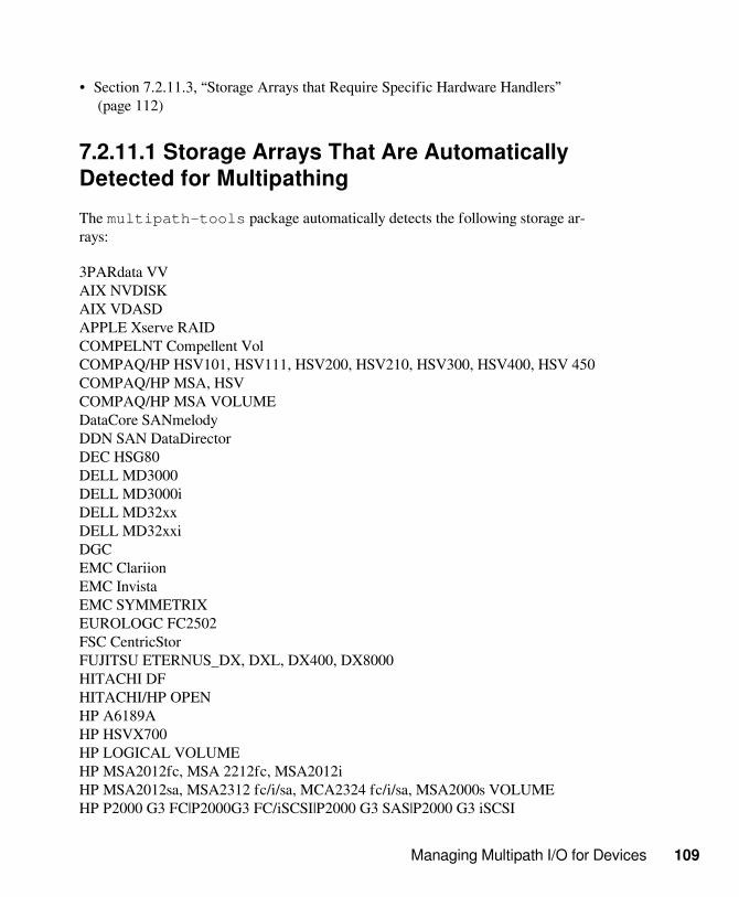
Managing Multipath I/O for Devices 109
• Section 7.2.11.3, “Storage Arrays that Require Specific Hardware Handlers” (page 112)
7.2.11.1 Storage Arrays That Are AutomaticallyDetected for MultipathingThe multipath-tools package automatically detects the following storage ar-rays:
3PARdata VVAIX NVDISKAIX VDASDAPPLE Xserve RAIDCOMPELNT Compellent VolCOMPAQ/HP HSV101, HSV111, HSV200, HSV210, HSV300, HSV400, HSV 450COMPAQ/HP MSA, HSVCOMPAQ/HP MSA VOLUMEDataCore SANmelodyDDN SAN DataDirectorDEC HSG80DELL MD3000DELL MD3000iDELL MD32xxDELL MD32xxiDGCEMC ClariionEMC InvistaEMC SYMMETRIXEUROLOGC FC2502FSC CentricStorFUJITSU ETERNUS_DX, DXL, DX400, DX8000HITACHI DFHITACHI/HP OPENHP A6189AHP HSVX700HP LOGICAL VOLUMEHP MSA2012fc, MSA 2212fc, MSA2012iHP MSA2012sa, MSA2312 fc/i/sa, MCA2324 fc/i/sa, MSA2000s VOLUMEHP P2000 G3 FC|P2000G3 FC/iSCSI|P2000 G3 SAS|P2000 G3 iSCSI

110 Storage Administration Guide
IBM 1722-600IBM 1724IBM 1726IBM 1742IBM 1745, 1746IBM 1750500IBM 1814IBM 1815IBM 1818IBM 1820N00IBM 2105800IBM 2105F20IBM 2107900IBM 2145IBM 2810XIVIBM 3303 NVDISKIBM 3526IBM 3542IBM IPRIBM NseriesIBM ProFibre 4000RIBM S/390 DASD ECKDIBM S/390 DASD FBAIntel Multi-FlexLSI/ENGENIO INF-01-00NEC DISK ARRAYNETAPP LUNNEXENTA COMSTARPillar AxiomPIVOT3 RAIGE VOLUMESGI ISSGI TP9100, TP 9300SGI TP9400, TP9500STK FLEXLINE 380STK OPENstorage D280SUN CSM200_RSUN LCSM100_[IEFS]SUN STK6580, STK6780SUN StorEdge 3510, T4SUN SUN_6180

Managing Multipath I/O for Devices 111
In general, most other storage arrays should work. When storage arrays are automat-ically detected, the default settings for multipathing apply. If you want non-defaultsettings, you must manually create and configure the /etc/multipath.conffile. For information, see Section 7.6, “Creating or Modifying the /etc/multipath.confFile” (page 131).
Testing of the IBM zSeries device with multipathing has shown thatthe dev_loss_tmo parameter should be set to 90 seconds, and thefast_io_fail_tmo parameter should be set to 5 seconds. If you are using zSeriesdevices, you must manually create and configure the /etc/multipath.conf fileto specify the values. For information, see Section 7.10, “Configuring Default Set-tings for zSeries Devices” (page 144).
Hardware that is not automatically detected requires an appropriate entry for config-uration in the devices section of the /etc/multipath.conf file. In this case,you must manually create and configure the configuration file. For information, seeSection 7.6, “Creating or Modifying the /etc/multipath.conf File” (page 131).
Consider the following caveats:
• Not all of the storage arrays that are automatically detected have been tested onSUSE Linux Enterprise Server. For information, see Section 7.2.11.2, “Tested Stor-age Arrays for Multipathing Support” (page 111).
• Some storage arrays might require specific hardware handlers. A hardware handleris a kernel module that performs hardware-specific actions when switching pathgroups and dealing with I/O errors. For information, see Section 7.2.11.3, “StorageArrays that Require Specific Hardware Handlers” (page 112).
• After you modify the /etc/multipath.conf file, you must run mkinitrdto re-create the INITRD on your system, then reboot in order for the changes totake effect.
7.2.11.2 Tested Storage Arrays for MultipathingSupportThe following storage arrays have been tested with SUSE Linux Enterprise Server:
EMCHitachi

112 Storage Administration Guide
Hewlett-Packard/CompaqIBMNetAppSGI
Most other vendor storage arrays should also work. Consult your vendor’s documen-tation for guidance. For a list of the default storage arrays recognized by the multipath-tools package, see Section 7.2.11.1, “Storage Arrays That Are Automatical-ly Detected for Multipathing” (page 109).
7.2.11.3 Storage Arrays that Require SpecificHardware HandlersStorage arrays that require special commands on failover from one path to the otheror that require special nonstandard error handling might require more extensive sup-port. Therefore, the Device Mapper Multipath service has hooks for hardware han-dlers. For example, one such handler for the EMC CLARiiON CX family of arrays isalready provided.
IMPORTANT
Consult the hardware vendor’s documentation to determine if its hardwarehandler must be installed for Device Mapper Multipath.
The multipath -t command shows an internal table of storage arrays that requirespecial handling with specific hardware handlers. The displayed list is not an exhaus-tive list of supported storage arrays. It lists only those arrays that require special han-dling and that the multipath-tools developers had access to during the tool de-velopment.
IMPORTANT
Arrays with true active/active multipath support do not require special han-dling, so they are not listed for the multipath -t command.
A listing in the multipath -t table does not necessarily mean that SUSELinux Enterprise Server was tested on that specific hardware. For a list of test-ed storage arrays, see Section 7.2.11.2, “Tested Storage Arrays for MultipathingSupport” (page 111).

Managing Multipath I/O for Devices 113
7.3 Multipath Management ToolsThe multipathing support in SUSE Linux Enterprise Server 10 and later is basedon the Device Mapper Multipath module of the Linux 2.6 kernel and the multi-path-tools userspace package. You can use the Multiple Devices Administrationutility (MDADM, mdadm) to view the status of multipathed devices.
• Section 7.3.1, “Device Mapper Multipath Module” (page 113)
• Section 7.3.2, “Multipath I/O Management Tools” (page 116)
• Section 7.3.3, “Using MDADM for Multipathed Devices” (page 117)
• Section 7.3.4, “Linux multipath(8) Command” (page 118)
• Section 7.3.5, “Linux mpathpersist(8) Utility” (page 123)
7.3.1 Device Mapper Multipath ModuleThe Device Mapper Multipath (DM-MP) module provides the multipathing capabilityfor Linux. DM-MPIO is the preferred solution for multipathing on SUSE Linux En-terprise Server 11. It is the only multipathing option shipped with the product that iscompletely supported by Novell and SUSE.
DM-MPIO features automatic configuration of the multipathing subsystem for a largevariety of setups. Configurations of up to 8 paths to each device are supported. Con-figurations are supported for active/passive (one path active, others passive) or ac-tive/active (all paths active with round-robin load balancing).
The DM-MPIO framework is extensible in two ways:
• Using specific hardware handlers. For information, see Section 7.2.11.3, “StorageArrays that Require Specific Hardware Handlers” (page 112).
• Using load-balancing algorithms that are more sophisticated than the round-robinalgorithm
The user-space component of DM-MPIO takes care of automatic path discovery andgrouping, as well as automated path retesting, so that a previously failed path is auto-matically reinstated when it becomes healthy again. This minimizes the need for ad-ministrator attention in a production environment.

114 Storage Administration Guide
DM-MPIO protects against failures in the paths to the device, and not failures in thedevice itself. If one of the active paths is lost (for example, a network adapter breaksor a fiber-optic cable is removed), I/O is redirected to the remaining paths. If the con-figuration is active/passive, then the path fails over to one of the passive paths. If youare using the round-robin load-balancing configuration, the traffic is balanced acrossthe remaining healthy paths. If all active paths fail, inactive secondary paths must bewaked up, so failover occurs with a delay of approximately 30 seconds.
If a disk array has more than one storage processor, ensure that the SAN switch has aconnection to the storage processor that owns the LUNs you want to access. On mostdisk arrays, all LUNs belong to both storage processors, so both connections are ac-tive.
NOTE
On some disk arrays, the storage array manages the traffic through stor-age processors so that it presents only one storage processor at a time. Oneprocessor is active and the other one is passive until there is a failure. If youare connected to the wrong storage processor (the one with the passivepath) you might not see the expected LUNs, or you might see the LUNs butget errors when you try to access them.
Table 7.1: Multipath I/O Features of Storage Arrays
Features of Stor-age Arrays
Description
Active/passivecontrollers
One controller is active and serves all LUNs. The sec-ond controller acts as a standby. The second controlleralso presents the LUNs to the multipath componentso that the operating system knows about redundantpaths. If the primary controller fails, the second con-troller takes over, and it serves all LUNs.
In some arrays, the LUNs can be assigned to differ-ent controllers. A given LUN is assigned to one con-troller to be its active controller. One controller doesthe disk I/O for any given LUN at a time, and the sec-ond controller is the standby for that LUN. The sec-ond controller also presents the paths, but disk I/O is

Managing Multipath I/O for Devices 115
Features of Stor-age Arrays
Description
not possible. Servers that use that LUN are connectedto the LUN’s assigned controller. If the primary con-troller for a set of LUNs fails, the second controllertakes over, and it serves all LUNs.
Active/active con-trollers
Both controllers share the load for all LUNs, and canprocess disk I/O for any given LUN. If one controllerfails, the second controller automatically handles alltraffic.
Load balancing The Device Mapper Multipath driver automaticallyload balances traffic across all active paths.
Controller failover When the active controller fails over to the passive, orstandby, controller, the Device Mapper Multipath dri-ver automatically activates the paths between the hostand the standby, making them the primary paths.
Boot/Root devicesupport
Multipathing is supported for the root (/) device inSUSE Linux Enterprise Server 10 and later. The hostserver must be connected to the currently active con-troller and storage processor for the boot device.
Multipathing is supported for the /boot device inSUSE Linux Enterprise Server 11 and later.
Device Mapper Multipath detects every path for a multipathed device as a separateSCSI device. The SCSI device names take the form /dev/sdN, where N is an auto-generated letter for the device, beginning with a and issued sequentially as the devicesare created, such as /dev/sda, /dev/sdb, and so on. If the number of devices ex-ceeds 26, the letters are duplicated so that the next device after /dev/sdz will benamed /dev/sdaa, /dev/sdab, and so on.
If multiple paths are not automatically detected, you can configure them manually inthe /etc/multipath.conf file. The multipath.conf file does not exist un-til you create and configure it. For information, see Section 7.6, “Creating or Modify-ing the /etc/multipath.conf File” (page 131).

116 Storage Administration Guide
7.3.2 Multipath I/O Management ToolsThe multipath-tools user-space package takes care of automatic path discoveryand grouping. It automatically tests the path periodically, so that a previously failedpath is automatically reinstated when it becomes healthy again. This minimizes theneed for administrator attention in a production environment.
Table 7.2: Tools in the multipath-tools Package
Tool Description
multipath Scans the system for multipathed devices and assem-bles them.
multipathd Waits for maps events, then executes multipath.
devmap-name Provides a meaningful device name to udev for de-vice maps (devmaps).
kpartx Maps linear devmaps to partitions on the multipatheddevice, which makes it possible to create multipathmonitoring for partitions on the device.
mpathpersist Manages SCSI persistent reservations on Device Map-per Multipath devices.
The file list for a package can vary for different server architectures. For a listof files included in the multipath-tools package, go to the SUSE Linux EnterpriseServer Technical Specifications > Package Descriptions Web page [http://www.novell.com/products/server/techspecs.html?tab=1],find your architecture and select Packages Sorted by Name, then search on “multi-path-tools” to find the package list for that architecture.
You can also determine the file list for an RPM file by querying the package itself:using the rpm -ql or rpm -qpl command options.
• To query an installed package, enter
rpm -ql <package_name>

Managing Multipath I/O for Devices 117
• To query a package not installed, enter
rpm -qpl <URL_or_path_to_package>
To check that the multipath-tools package is installed, do the following:
• Enter the following at a terminal console prompt:
rpm -q multipath-tools
If it is installed, the response repeats the package name and provides the version in-formation, such as:
multipath-tools-04.7-34.23
If it is not installed, the response reads:
package multipath-tools is not installed
7.3.3 Using MDADM for MultipathedDevicesUdev is the default device handler, and devices are automatically known to the sys-tem by the Worldwide ID instead of by the device node name. This resolves prob-lems in previous releases of MDADM and LVM where the configuration files(mdadm.conf and lvm.conf) did not properly recognize multipathed devices.
Just as for LVM2, MDADM requires that the devices be accessed by the ID ratherthan by the device node path. Therefore, the DEVICE entry in /etc/mdadm.confshould be set as follows:
DEVICE /dev/disk/by-id/*
If you are using user-friendly names, specify the path as follows so that only the de-vice mapper names are scanned after multipathing is configured:
DEVICE /dev/disk/by-id/dm-uuid-.*-mpath-.*
To verify that MDADM is installed:

118 Storage Administration Guide
• Ensure that the mdadm package is installed by entering the following at a terminalconsole prompt:
rpm -q mdadm
If it is installed, the response repeats the package name and provides the version in-formation. For example:
mdadm-2.6-0.11
If it is not installed, the response reads:
package mdadm is not installed
For information about modifying the /etc/lvm/lvm.conffile, see Section 7.2.4,“Using LVM2 on Multipath Devices” (page 102).
7.3.4 Linux multipath(8) CommandUse the Linux multipath(8) command to configure and manage multipathed de-vices.
General syntax for the multipath(8) command:
multipath [-v verbosity_level] [-b bindings_file] [-d] [-h|-l|-ll|-f|-F|-B|-c|-q|-r|-w|-W] [-p failover|multibus|group_by_serial|group_by_prio|group_by_node_name] [devicename]
Options-v verbosity_level
Prints all paths and multipaths.
0No output.
1Prints only the created or updated multipath names. Used to feed other toolslike kpartx.
2+Print all information: Detected paths, multipaths, and device maps.

Managing Multipath I/O for Devices 119
-hPrint usage text.
-dDry run; do not create or update device maps.
-lShow the current multipath topology from information fetched in sysfs and thedevice mapper.
-llShow the current multipath topology from all available information (sysfs, the de-vice mapper, path checkers, and so on).
-fFlush a multipath device map specified as a parameter, if unused.
-FFlush all unused multipath device maps.
-tPrint internal hardware table to stdout.
-rForce device map reload.
-BTreat the bindings file as read only.
-b bindings_fileSet the user_friendly_names bindings file location. The default is /etc/multipath/bindings.
-cCheck if a block device should be a path in a multipath device.
-qAllow device tables with queue_if_no_path when multipathd is not run-ning.
-wRemove the WWID for the specified device from the WWIDs file.

120 Storage Administration Guide
-WReset the WWIDs file to only include the current multipath devices.
-p policyForce new maps to use the specified policy. Existing maps are not modified.
failoverOne path per priority group.
multibusAll paths in one priority group.
group_by_serialOne priority group per serial.
group_by_prioOne priority group per priority value. Priorities are determined by calloutprograms specified as a global, per-controller or per-multipath option in theconfiguration file.
group_by_node_nameOne priority group per target node name. Target node names are fetched in /sys/class/fc_transport/target*/node_name.
device_nameUpdate only the device map for the specified device. Specify the name as the de-vice path such as /dev/sdb, or in major:minor format, or the multipathmap name.
General Examplesmultipath
Configure all multipath devices.
multipath devicenameConfigures a specific multipath device.
Replace devicename with the device node name such as /dev/sdb (asshown by udev in the $DEVNAME variable), or in the major:minor format.The device may alternatively be a multipath map name.

Managing Multipath I/O for Devices 121
multipath -fSelectively suppresses a multipath map, and its device-mapped partitions.
multipath -dDry run. Displays potential multipath devices, but does not create any devices anddoes not update device maps.
multipath -v2 -dDisplays multipath map information for potential multipath devices in a dry run.The -v2 option shows only local disks. This verbosity level prints the created orupdated multipath names only for use to feed other tools like kpartx.
There is no output if the devices already exists and there are no changes. Usemultipath -ll to see the status of configured multipath devices.
multipath -v2 devicenameConfigures a specific potential multipath device and displays multipath map in-formation for it. This verbosity level prints only the created or updated multipathnames for use to feed other tools like kpartx.
There is no output if the device already exists and there are no changes. Usemultipath -ll to see the status of configured multipath devices.
Replace devicename with the device node name such as /dev/sdb (asshown by udev in the $DEVNAME variable), or in the major:minor format.The device may alternatively be a multipath map name.
multipath -v3Configures potential multipath devices and displays multipath map informationfor them. This verbosity level prints all detected paths, multipaths, and devicemaps. Both wwid and devnode blacklisted devices are displayed.
multipath -v3 devicenameConfigures a specific potential multipath device and displays information for it.The -v3 option shows the full path list. This verbosity level prints all detectedpaths, multipaths, and device maps. Both wwid and devnode blacklisted devicesare displayed.
Replace devicename with the device node name such as /dev/sdb (asshown by udev in the $DEVNAME variable), or in the major:minor format.The device may alternatively be a multipath map name.

122 Storage Administration Guide
multipath -llDisplay the status of all multipath devices.
multipath -ll devicenameDisplays the status of a specified multipath device.
Replace devicename with the device node name such as /dev/sdb (asshown by udev in the $DEVNAME variable), or in the major:minor format.The device may alternatively be a multipath map name.
multipath -FFlushes all unused multipath device maps. This unresolves the multiple paths; itdoes not delete the devices.
multipath -F devicenameFlushes unused multipath device maps for a specified multipath device. This un-resolves the multiple paths; it does not delete the device.
Replace devicename with the device node name such as /dev/sdb (asshown by udev in the $DEVNAME variable), or in the major:minor format.The device may alternatively be a multipath map name.
multipath -p [ failover | multibus | group_by_serial | group_by_prio |group_by_node_name ]
Sets the group policy by specifying one of the group policy options thatare described in Table 7.3, “Group Policy Options for the multipath -pCommand” (page 122):
Table 7.3: Group Policy Options for the multipath -p Command
Policy Option Description
failover (Default) One path per priority group. You can useonly one path at a time.
multibus All paths in one priority group.
group_by_serial One priority group per detected SCSI serial number(the controller node worldwide number).
group_by_prio One priority group per path priority value. Paths withthe same priority are in the same priority group. Prior-

Managing Multipath I/O for Devices 123
Policy Option Description
ities are determined by callout programs specified as aglobal, per-controller, or per-multipath option in the /etc/multipath.conf configuration file.
group_by_node_nameOne priority group per target node name. Targetnode names are fetched in the/sys/class/fc_transport/target*/node_name location.
7.3.5 Linux mpathpersist(8) UtilityThe mpathpersist(8) utility can be used to manage SCSI persistent reservationson Device Mapper Multipath devices.
General syntax for the mpathpersist(8) command:
mpathpersist [options] [device]
Use this utility with the service action reservation key (reservation_key at-tribute) in the /etc/multipath.conf file to set persistent reservations for SCSIdevices. The attribute is not used by default. If it is not set, the multipathd dae-mon does not check for persistent reservation for newly discovered paths or reinstatedpaths.
reservation_key <reservation key>
You can add the attribute to the defaults section or the multipaths section.For example:
multipaths { multipath { wwid XXXXXXXXXXXXXXXX alias yellow reservation_key 0x123abc }}
Set the reservation_key parameter for all mpath devices applicable for persis-tent management, then restart the multipathd daemon. After it is set up, you canspecify the reservation key in the mpathpersist commands.

124 Storage Administration Guide
Options-h , --help
Outputs the command usage information, then exits.
-d <device> , --device=<device>Query or change the device.
-H , --hexDisplay the output response in hexadecimal.
-X <tids> , --transportID=<tids>Transport IDs can be mentioned in several forms.
-v <level> , --verbose <level>Specifies the verbosity level.
0Critical and error messages.
1Warning messages.
2Informational messages.
3Informational messages with trace enabled.
PR In Options-i , --in
Request PR In command.
-k , --read-keysPR In: Read Keys.
-s , --read-statusPR In: Read Full Status.
-r , --read-reservationPR In: Read Reservation.

Managing Multipath I/O for Devices 125
-c , --report-capabilitiesPR In: Report Capabilities.
PR Out Options-o , --out
Request PR Out command.
-c , --clearPR Out: Clear
-Z , --param-aptplPR Out parameter APTPL.
-S SARK , --param-sark=SARKPR Out parameter Service Action Reservation Key (SARK) in hexadecimal.
-P , --preemptPR Out: Preempt.
-A , --preempt-abortPR Out: Preempt and Abort.
-T <type> , --prout-type=<type>PR Out command type.
-G , --registerPR Out: Register.
-I , --register-ignorePR Out: Register and Ignore.
-L , --releasePR Out: Release
-R , --reservePR Out: Reserve.
ExamplesRegister the Service Action Reservation Key for the /dev/mapper/mpath9 de-vice.

126 Storage Administration Guide
mpathpersist --out --register --param-sark=123abc --prout-type=5 -d /dev/mapper/mpath9
Read the Service Action Reservation Key for the /dev/mapper/mpath9 device.
mpathpersisst -i -k -d /dev/mapper/mpath9
Reserve the Service Action Reservation Key for the /dev/mapper/mpath9 de-vice.
mpathpersist --out --reserve --param-sark=123abc --prout-type=8 -d /dev/mapper/mpath9
Read the reservation status of the /dev/mapper/mpath9 device.
mpathpersist -i -s -d /dev/mapper/mpath9
7.4 Configuring the System forMultipathing• Section 7.4.1, “Preparing SAN Devices for Multipathing” (page 126)
• Section 7.4.2, “Partitioning Multipath Devices” (page 127)
• Section 7.4.3, “Configuring the Device Drivers in initrd for Multipathing ” (page 128)
• Section 7.4.4, “Adding multipathd to the Boot Sequence” (page 129)
7.4.1 Preparing SAN Devices forMultipathingBefore configuring multipath I/O for your SAN devices, prepare the SAN devices, asnecessary, by doing the following:
• Configure and zone the SAN with the vendor’s tools.
• Configure permissions for host LUNs on the storage arrays with the vendor’s tools.

Managing Multipath I/O for Devices 127
• Install the Linux HBA driver module. Upon module installation, the driver auto-matically scans the HBA to discover any SAN devices that have permissions for thehost. It presents them to the host for further configuration.
NOTE
Ensure that the HBA driver you are using does not have native multipathingenabled.
See the vendor’s specific instructions for more details.
• After the driver module is loaded, discover the device nodes assigned to specific ar-ray LUNs or partitions.
• If the SAN device will be used as the root device on the server, modify the timeoutsettings for the device as described in Section 7.2.8, “SAN Timeout Settings Whenthe Root Device Is Multipathed” (page 106).
If the LUNs are not seen by the HBA driver, lsscsi can be used to check whetherthe SCSI devices are seen correctly by the operating system. When the LUNs arenot seen by the HBA driver, check the zoning setup of the SAN. In particular, checkwhether LUN masking is active and whether the LUNs are correctly assigned to theserver.
If the LUNs are seen by the HBA driver, but there are no corresponding block de-vices, additional kernel parameters are needed to change the SCSI device scanningbehavior, such as to indicate that LUNs are not numbered consecutively. For infor-mation, see TID 3955167: Troubleshooting SCSI (LUN) Scanning Issues in the NovellSupport Knowledgebase [http://support.novell.com/].
7.4.2 Partitioning Multipath DevicesPartitioning devices that have multiple paths is not recommended, but it is support-ed. You can use the kpartx tool to create partitions on multipath devices withoutrebooting. You can also partition the device before you attempt to configure multi-pathing by using the Partitioner function in YaST, or by using a third-party partition-ing tool.
Multipath devices are device-mapper devices. Modifying device-mapper devices withcommand line tools (such as parted, kpartx, or fdisk) works, but it does not necessar-

128 Storage Administration Guide
ily generate the udev events that are required to update other layers. After you parti-tion the device-mapper device, you should check the multipath map to make sure thedevice-mapper devices were mapped. If they are missing, you can remap the multi-path devices or reboot the server to pick up all of the new partitions in the multipathmap.
The device-mapper device for a partition on a multipath device is not the same as anindependent device. When you create an LVM logical volume using the whole device,you must specify a device that contains no partitions. If you specify a multipath par-tition as the target device for the LVM logical volume, LVM recognizes that the un-derlying physical device is partitioned and the create fails. If you need to subdivide aSAN device, you can carve LUNs on the SAN device and present each LUN as a sep-arate multipath device to the server.
7.4.3 Configuring the Device Drivers ininitrd for MultipathingThe server must be manually configured to automatically load the device drivers forthe controllers to which the multipath I/O devices are connected within the initrd.You need to add the necessary driver module to the variable INITRD_MODULES inthe file /etc/sysconfig/kernel.
For example, if your system contains a RAID controller accessed by the cciss dri-ver and multipathed devices connected to a QLogic controller accessed by the driverqla2xxx, this entry would look like:
INITRD_MODULES="cciss"
Because the QLogic driver is not automatically loaded on startup, add it here:
INITRD_MODULES="cciss qla23xx"
After changing /etc/sysconfig/kernel, you must re-create the initrd onyour system with the mkinitrd command, then reboot in order for the changes totake effect.
When you are using LILO as a boot manager, reinstall it with the /sbin/lilocommand. No further action is required if you are using GRUB.
In SUSE Linux Enterprise Server 11 SP3 and later, four SCSI hardware handlers wereadded in the SCSI layer that can be used with DM-Multipath:

Managing Multipath I/O for Devices 129
scsi_dh_aluascsi_dh_rdacscsi_dh_hp_swscsi_dh_emc
Add the modules to the initrd image, then specify them in the /etc/multipath.conf file as hardware handler types alua, rdac, hp_sw, and emc.For example, add one of these lines for a device definition:
hardware_handler "1 alua"
hardware_handler "1 rdac"
hardware_handler "1 hp_sw"
hardware_handler "1 emc"
To include the modules in the initrd image:
1 Add the device handler modules to the INITRD_MODULES variable in /etc/sysconfig/kernel.
2 Create a new initrd:
mkinitrd -k /boot/vmlinux-<flavour> \-i /boot/initrd-<flavour>-scsi-dh \-M /boot/System.map-<flavour>
3 Update the boot configuration file (grub.conf, lilo.conf, yaboot.conf)with the newly built initrd.
4 Restart the server.
7.4.4 Adding multipathd to the BootSequenceUse either of the methods in this section to add multipath I/O services (multi-pathd) to the boot sequence.
• Section 7.4.4.1, “Using YaST to Add multipathd” (page 130)
• Section 7.4.4.2, “Using the Command Line to Add multipathd” (page 130)

130 Storage Administration Guide
7.4.4.1 Using YaST to Add multipathd1 In YaST, click System > System Services (Runlevel) > Simple Mode.
2 Select multipathd, then click Enable.
3 Click OK to acknowledge the service startup message.
4 Click Finish, then click Yes.
The changes do not take affect until the server is restarted.
7.4.4.2 Using the Command Line to Addmultipathd1 Open a terminal console, then log in as the root user or equivalent.
2 At the terminal console prompt, enter
insserv multipathd
7.5 Enabling and Starting MultipathI/O ServicesTo start multipath services and enable them to start at reboot:
1 Open a terminal console, then log in as the root user or equivalent.
2 At the terminal console prompt, enter
chkconfig multipathd on
chkconfig boot.multipath on
If the boot.multipath service does not start automatically on system boot, do the fol-lowing to start them manually:
1 Open a terminal console, then log in as the root user or equivalent.

Managing Multipath I/O for Devices 131
2 Enter
/etc/init.d/boot.multipath start
/etc/init.d/multipathd start
7.6 Creating or Modifying the /etc/multipath.conf FileThe /etc/multipath.conf file does not exist unless you create it. De-fault multipath device settings are applied automatically when the multi-pathd daemon runs unless you create the multipath configuration file andpersonalize the settings. The /usr/share/doc/packages/multipath-tools/multipath.conf.synthetic file contains a sample /etc/multipath.conf file that you can use as a guide for multipath settings.
Whenever you create or modify the /etc/multipath.conf file, the changesare not automatically applied when you save the file. This allows you time to performa dry run to verify your changes before they are committed. When you are satisfiedwith the revised settings, you can update the multipath maps for the running multi-pathd daemon to use, or the changes will be applied the next time that the multipathddaemon is restarted, such as on a system restart.
• Section 7.6.1, “Creating the /etc/multipath.conf File” (page 131)
• Section 7.6.2, “Sections in the /etc/multipath.conf File” (page 132)
• Section 7.6.3, “Verifying the Multipath Setup in the /etc/multipath.conf File” (page 134)
• Section 7.6.4, “Applying the /etc/multipath.conf File Changes to Update the Multi-path Maps” (page 136)
7.6.1 Creating the /etc/multipath.conf FileIf the /etc/multipath.conf file does not exist, copy the example to create thefile:
1 In a terminal console, log in as the root user.

132 Storage Administration Guide
2 Enter the following command (all on one line, of course) to copy the template:
cp /usr/share/doc/packages/multipath-tools/multipath.conf.synthetic /etc/multipath.conf
3 Use the /usr/share/doc/packages/multipath-tools/multipath.conf.annotated file as a reference to determine how to config-ure multipathing for your system.
4 Ensure that there is an appropriate device entry for your SAN. Most vendorsprovide documentation on the proper setup of the device section.
The /etc/multipath.conf file requires a different device sectionfor different SANs. If you are using a storage subsystem that is automatical-ly detected (see Section 7.2.11.2, “Tested Storage Arrays for MultipathingSupport” (page 111)), the default entry for that device can be used; no furtherconfiguration of the /etc/multipath.conf file is required.
5 Save the file.
7.6.2 Sections in the /etc/multipath.confFileThe /etc/multipath.conf file is organized in the following sec-tions. See /usr/share/doc/packages/multipath-tools/multipath.conf.annotated for a template with extensive comments for eachof the attributes and their options.
defaultsGeneral default settings for multipath I/0. These values are used if no val-ues are given in the appropriate device or multipath sections. For informa-tion, see Section 7.7, “Configuring Default Policies for Polling, Queueing, andFailback” (page 136).
blacklistLists the device names to discard as not multipath candidates. Devices can beidentified by their device node name (devnode), their WWID (wwid), or theirvendor or product strings (device). For information, see Section 7.8, “Blacklist-ing Non-Multipath Devices” (page 138).

Managing Multipath I/O for Devices 133
You typically ignore non-multipathed devices, such as cciss, fd, hd, md, dm,sr, scd, st, ram, raw, and loop.
Values
For an example, see Section 7.8, “Blacklisting Non-MultipathDevices” (page 138).
blacklist_exceptionsLists the device names of devices to be treated as multipath candidates even ifthey are on the blacklist. Devices can be identified by their device node name(devnode), their WWID (wwid), or their vendor or product strings (device).You must specify the excepted devices by using the same keyword that you usedin the blacklist. For example, if you used the devnode keyword for devices inthe blacklist, you use the devnode keyword to exclude some of the devices in theblacklist exceptions. It is not possible to blacklist devices by using the devnodekeyword and to exclude some devices of them by using the wwid keyword.
Values
For examples, see Section 7.8, “Blacklisting Non-MultipathDevices” (page 138) and the /usr/share/doc/packages/multipath-tools/multipath.conf.annotated file.
multipathsSpecifies settings for individual multipath devices. Except for settings that do notsupport individual settings, these values overwrite what is specified in the de-faults and devices sections of the configuration file.
devicesSpecifies settings for individual storage controllers. These values overwrite valuesspecified in the defaults section of the configuration file. If you use a storagearray that is not supported by default, you can create a devices subsection tospecify the default settings for it. These values can be overwritten by settings forindividual multipath devices if the keyword allows it.
For information, see the following:
• Section 7.9, “Configuring User-Friendly Names or Alias Names” (page 140)
• Section 7.10, “Configuring Default Settings for zSeries Devices” (page 144)

134 Storage Administration Guide
7.6.3 Verifying the Multipath Setup in the /etc/multipath.conf FileWhenever you create or modify the /etc/multipath.conf file, the changes arenot automatically applied when you save the file. You can perform a “dry run” of thesetup to verify the multipath setup before you update the multipath maps.
At the server command prompt, enter
multipath -v2 -d
This command scans the devices, then displays what the setup would look like ifyou commit the changes. It is assumed that the multipathd daemon is alreadyrunning with the old (or default) multipath settings when you modify the /etc/multipath.conf file and perform the dry run. If the changes are acceptable, con-tinue with Section 7.6.4, “Applying the /etc/multipath.conf File Changes to Updatethe Multipath Maps” (page 136).
The output is similar to the following:
26353900f02796769[size=127 GB][features="0"][hwhandler="1 emc"]
\_ round-robin 0 [first] \_ 1:0:1:2 sdav 66:240 [ready ] \_ 0:0:1:2 sdr 65:16 [ready ]
\_ round-robin 0 \_ 1:0:0:2 sdag 66:0 [ready ] \_ 0:0:0:2 sdc 8:32 [ready ]
Paths are grouped into priority groups. Only one priority group is in active use at atime. To model an active/active configuration, all paths end in the same group. Tomodel active/passive configuration, the paths that should not be active in parallel areplaced in several distinct priority groups. This normally happens automatically on de-vice discovery.
The output shows the order, the scheduling policy used to balance I/O within thegroup, and the paths for each priority group. For each path, its physical address(host:bus:target:lun), device node name, major:minor number, and state is shown.

Managing Multipath I/O for Devices 135
By using a verbosity level of -v3 in the dry run, you can see all detected paths, mul-tipaths, and device maps. Both WWID and device node blacklisted devices are dis-played.
multipath -v3 d
The following is an example of -v3 output on a 64-bit SLES 11 SP2 server with twoQlogic HBA connected to a Xiotech Magnitude 3000 SAN. Some multiple entrieshave been omitted to shorten the example.
dm-22: device node name blacklisted< content omitted >loop7: device node name blacklisted< content omitted >md0: device node name blacklisted< content omitted >dm-0: device node name blacklistedsdf: not found in pathvecsdf: mask = 0x1fsdf: dev_t = 8:80sdf: size = 105005056sdf: subsystem = scsisdf: vendor = XIOtechsdf: product = Magnitude 3Dsdf: rev = 3.00sdf: h:b:t:l = 1:0:0:2sdf: tgt_node_name = 0x202100d0b2028dasdf: serial = 000028DA0014sdf: getuid= "/lib/udev/scsi_id --whitelisted --device=/dev/%n" (config file default)sdf: uid = 200d0b2da28001400 (callout)sdf: prio = const (config file default)sdf: const prio = 1< content omitted >ram15: device node name blacklisted< content omitted >===== paths list =====uuid hcil dev dev_t pri dm_st chk_st vend/prod/rev200d0b2da28001400 1:0:0:2 sdf 8:80 1 [undef][undef] XIOtech,Magnitude 3D200d0b2da28005400 1:0:0:1 sde 8:64 1 [undef][undef] XIOtech,Magnitude 3D200d0b2da28004d00 1:0:0:0 sdd 8:48 1 [undef][undef] XIOtech,Magnitude 3D200d0b2da28001400 0:0:0:2 sdc 8:32 1 [undef][undef] XIOtech,Magnitude 3D200d0b2da28005400 0:0:0:1 sdb 8:16 1 [undef][undef] XIOtech,Magnitude 3D200d0b2da28004d00 0:0:0:0 sda 8:0 1 [undef][undef] XIOtech,Magnitude 3Dparams = 0 0 2 1 round-robin 0 1 1 8:80 1000 round-robin 0 1 1 8:32 1000status = 2 0 0 0 2 1 A 0 1 0 8:80 A 0 E 0 1 0 8:32 A 0sdf: mask = 0x4sdf: path checker = directio (config file default)directio: starting new requestdirectio: async io getevents returns 1 (errno=Success)directio: io finished 4096/0

136 Storage Administration Guide
sdf: state = 2< content omitted >
7.6.4 Applying the /etc/multipath.conf FileChanges to Update the Multipath MapsChanges to the /etc/multipath.conf file cannot take effect when multi-pathd is running. After you make changes, save and close the file, then do the fol-lowing to apply the changes and update the multipath maps:
1 Stop the multipathd service.
2 Clear old multipath bindings by entering
/sbin/multipath -F
3 Create new multipath bindings by entering
/sbin/multipath -v2 -l
4 Start the multipathd service.
5 Run mkinitrd to re-create the initrd image on your system, then reboot inorder for the changes to take effect.
7.7 Configuring Default Policies forPolling, Queueing, and FailbackThe goal of multipath I/O is to provide connectivity fault tolerance between the stor-age system and the server. The desired default behavior depends on whether the serv-er is a standalone server or a node in a high-availability cluster.
When you configure multipath I/O for a stand-alone server, the no_path_retrysetting protects the server operating system from receiving I/O errors as long as pos-sible. It queues messages until a multipath failover occurs and provides a healthy con-nection.
When you configure multipath I/O for a node in a high-availability cluster, you wantmultipath to report the I/O failure in order to trigger the resource failover instead

Managing Multipath I/O for Devices 137
of waiting for a multipath failover to be resolved. In cluster environments, you mustmodify the no_path_retry setting so that the cluster node receives an I/O errorin relation to the cluster verification process (recommended to be 50% of the heart-beat tolerance) if the connection is lost to the storage system. In addition, you wantthe multipath I/O fail back to be set to manual in order to avoid a ping-pong of re-sources because of path failures.
The /etc/multipath.conf file should contain a defaults section where youcan specify default behaviors for polling, queueing, and failback. If the field is nototherwise specified in a device section, the default setting is applied for that SANconfiguration.
The following are the compiled in default settings. They will be used unlessyou overwrite these values by creating and configuring a personalized /etc/multipath.conf file.
defaults { verbosity 2# udev_dir is deprecated in SLES 11 SP3 and later# udev_dir /dev polling_interval 5# path_selector default value is service-time in SLES 11 SP3 and later# path_selector "round-robin 0" path selector "service-time 0" path_grouping_policy failover# getuid_callout is deprecated in SLES 11 SP3 and later and replaced with# uid_attribute# getuid_callout "/lib/udev/scsi_id --whitelisted --device=/dev/%n"# uid_attribute is new in SLES 11 SP3 uid_attribute "ID_SERIAL" prio "const" prio_args "" features "0" path_checker "directio" alias_prefix "mpath" rr_min_io_rq 1 max_fds "max" rr_weight "uniform" queue_without_daemon "yes" flush_on_last_del "no" user_friendly_names "no" fast_io_fail_tmo 5 bindings_file "/etc/multipath/bindings" wwids_file "/etc/multipath/wwids" log_checker_err "always" retain_attached_hw_handler "no" detect_prio "no" failback "manual" no_path_retry "fail"
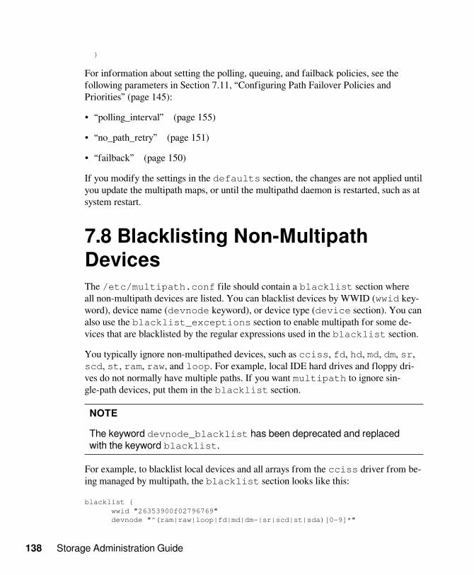
138 Storage Administration Guide
}
For information about setting the polling, queuing, and failback policies, see thefollowing parameters in Section 7.11, “Configuring Path Failover Policies andPriorities” (page 145):
• “polling_interval” (page 155)
• “no_path_retry” (page 151)
• “failback” (page 150)
If you modify the settings in the defaults section, the changes are not applied untilyou update the multipath maps, or until the multipathd daemon is restarted, such as atsystem restart.
7.8 Blacklisting Non-MultipathDevicesThe /etc/multipath.conf file should contain a blacklist section whereall non-multipath devices are listed. You can blacklist devices by WWID (wwid key-word), device name (devnode keyword), or device type (device section). You canalso use the blacklist_exceptions section to enable multipath for some de-vices that are blacklisted by the regular expressions used in the blacklist section.
You typically ignore non-multipathed devices, such as cciss, fd, hd, md, dm, sr,scd, st, ram, raw, and loop. For example, local IDE hard drives and floppy dri-ves do not normally have multiple paths. If you want multipath to ignore sin-gle-path devices, put them in the blacklist section.
NOTE
The keyword devnode_blacklist has been deprecated and replacedwith the keyword blacklist.
For example, to blacklist local devices and all arrays from the cciss driver from be-ing managed by multipath, the blacklist section looks like this:
blacklist { wwid "26353900f02796769" devnode "^(ram|raw|loop|fd|md|dm-|sr|scd|st|sda)[0-9]*"

Managing Multipath I/O for Devices 139
devnode "^hd[a-z][0-9]*" devnode "^cciss.c[0-9]d[0-9].*"}
You can also blacklist only the partitions from a driver instead of the entire array. Forexample, you can use the following regular expression to blacklist only partitions fromthe cciss driver and not the entire array:
blacklist { devnode "^cciss.c[0-9]d[0-9]*[p[0-9]*]"}
You can blacklist by specific device types by adding a device section in the black-list, and using the vendor and product keywords.
blacklist { device { vendor "DELL" product "*" }}
You can use a blacklist_exceptions section to enable multipath for some de-vices that were blacklisted by the regular expressions used in the blacklist sec-tion. You add exceptions by WWID (wwid keyword), device name (devnode key-word), or device type (device section). You must specify the exceptions in the sameway that you blacklisted the corresponding devices. That is, wwid exceptions applyto a wwid blacklist, devnode exceptions apply to a devnode blacklist, and devicetype exceptions apply to a device type blacklist.
For example, you can enable multipath for a desired device type when you have dif-ferent device types from the same vendor. Blacklist all of the vendor’s device typesin the blacklist section, and then enable multipath for the desired device type byadding a device section in a blacklist_exceptions section.
blacklist { devnode "^(ram|raw|loop|fd|md|dm-|sr|scd|st|sda)[0-9]*" device { vendor "DELL" product "*" }}
blacklist_exceptions { device { vendor "DELL" product "MD3220i" }

140 Storage Administration Guide
}
You can also use the blacklist_exceptions to enable multipath only for specific de-vices. For example:
blacklist { wwid "*"}
blacklist_exceptions { wwid "3600d0230000000000e13955cc3751234" wwid "3600d0230000000000e13955cc3751235"}
After you modify the /etc/multipath.conf file, you must run mkinitrd tore-create the initrd on your system, then restart the server in order for the changesto take effect.
After you do this, the local devices should no longer be listed in the multipath mapswhen you issue the multipath -ll command.
7.9 Configuring User-FriendlyNames or Alias NamesA multipath device can be identified by its WWID, by a user-friendly name, orby an alias that you assign for it. Before you begin, review the requirements inSection 7.2.3, “Using WWID, User-Friendly, and Alias Names for MultipathedDevices” (page 101).
IMPORTANT
Because device node names in the form of /dev/sdn and /dev/dm-n canchange on reboot, referring to multipath devices by their WWID is preferred.You can also use a user-friendly name or alias that is mapped to the WWIDin order to identify the device uniquely across reboots.
Table 7.4, “Comparison of Multipath Device Name Types” (page 141)describes the types of device names that can be used for a device in the /etc/multipath.conf file. For an example of multipath.conf set-tings, see the /usr/share/doc/packages/multipath-tools/multipath.conf.synthetic file.

Managing Multipath I/O for Devices 141
Table 7.4: Comparison of Multipath Device Name Types
NameTypes
Description
WWID(default)
The serial WWID (Worldwide Identifier) is an identifi-er for the multipath device that is guaranteed to be global-ly unique and unchanging. The default name used in multi-pathing is the ID of the logical unit as found in the /dev/disk/by-id directory. For example, a device with theWWID of 3600508e0000000009e6baa6f609e7908is listed as /dev/disk/by-id/scsi-3600508e0000000009e6baa6f609e7908.
User-friendly
The Device Mapper Multipath device names in the /dev/mapper directory also reference the ID of the logical unit.These multipath device names are user-friendly names in theform of /dev/mapper/mpath<n>, such as /dev/mapper/mpath0. The names are unique and persistent becausethey use the /var/lib/multipath/bindings file totrack the association between the UUID and user-friendlynames.
Alias An alias name is a globally unique name that the administra-tor provides for a multipath device. Alias names override theWWID and the user-friendly /dev/mapper/mpathN names.
If you are using user_friendly_names, do not set the alias tompathN format. This may conflict with an automatically as-signed user friendly name, and give you incorrect device nodenames.
The global multipath user_friendly_names option in the /etc/multipath.conf file is used to enable or disable the use of user-friendly namesfor multipath devices. If it is set to “no” (the default), multipath uses the WWID asthe name of the device. If it is set to “yes”, multipath uses the /var/lib/multipath/bindings file to assign a persistent and unique name to the device in theform of mpath<n> in the /dev/mapperdirectory. The bindings file optionin the /etc/multipath.conf file can be used to specify an alternate location forthe bindings file.

142 Storage Administration Guide
The global multipath alias option in the /etc/multipath.conf file is usedto explicitly assign a name to the device. If an alias name is set up for a multipath de-vice, the alias is used instead of the WWID or the user-friendly name.
Using the user_friendly_names option can be problematic in the following sit-uations:
• Root Device Is Using Multipath: If the system root device is using multipath andyou use the user_friendly_names option, the user-friendly settings in the /var/lib/multipath/bindings file are included in the initrd. If you lat-er change the storage setup, such as by adding or removing devices, there is a mis-match between the bindings setting inside the initrd and the bindings settings in/var/lib/multipath/bindings.
WARNING
A bindings mismatch between initrd and /var/lib/multipath/bindings can lead to a wrong assignment of mount points to de-vices, which can result in file system corruption and data loss.
To avoid this problem, we recommend that you use the default WWID settings forthe system root device. You should not use aliases for the system root device. Be-cause the device name would differ, using an alias causes you to lose the ability toseamlessly switch off multipathing via the kernel command line.
• Mounting /var from Another Partition: The default location of theuser_friendly_names configuration file is /var/lib/multipath/bindings. If the /var data is not located on the system root device butmounted from another partition, the bindings file is not available when settingup multipathing.
Ensure that the /var/lib/multipath/bindings file is available on the sys-tem root device and multipath can find it. For example, this can be done as follows:
1. Move the /var/lib/multipath/bindings file to /etc/multipath/bindings.
2. Set the bindings_file option in the defaults section of /etc/multipath.conf to this new location. For example:
defaults {

Managing Multipath I/O for Devices 143
user_friendly_names yes bindings_file "/etc/multipath/bindings"}
• Multipath Is in the initrd: Even if the system root device is not on multipath, it ispossible for multipath to be included in the initrd. For example, this can happenof the system root device is on LVM. If you use the user_friendly_namesoption and multipath is in the initrd, you should boot with the parametermultipath=off to avoid problems.
This disables multipath only in the initrd during system boots. After the systemboots, the boot.multipath and multipathd boot scripts are able to activatemultipathing.
To enable user-friendly names or to specify aliases:
1 In a terminal console, log in as the root user.
2 Open the /etc/multipath.conf file in a text editor.
3 (Optional) Modify the location of the /var/lib/multipath/bindingsfile.
The alternate path must be available on the system root device where multipath canfind it.
3a Move the /var/lib/multipath/bindings file to /etc/multipath/bindings.
3b Set the bindings_file option in the defaults section of /etc/multipath.conf to this new location. For example:
defaults { user_friendly_names yes bindings_file "/etc/multipath/bindings"}
4 (Optional, not recommended) Enable user-friendly names:
4a Uncomment the defaults section and its ending bracket.
4b Uncomment the user_friendly_names option, then change itsvalue from No to Yes.

144 Storage Administration Guide
For example:
## Use user friendly names, instead of using WWIDs as names.defaults { user_friendly_names yes}
5 (Optional) Specify your own names for devices by using the alias option in themultipath section.
For example:
## Use alias names, instead of using WWIDs as names.multipaths { multipath { wwid 36006048000028350131253594d303030 alias blue1 } multipath { wwid 36006048000028350131253594d303041 alias blue2 } multipath { wwid 36006048000028350131253594d303145 alias yellow1 } multipath { wwid 36006048000028350131253594d303334 alias yellow2 }}
6 Save your changes, then close the file.
The changes are not applied until you update the multipath maps, or until the multi-pathd daemon is restarted, such as at system restart.
7.10 Configuring Default Settingsfor zSeries DevicesTesting of the IBM zSeries device with multipathing has shown that the dev_loss_tmoparameter should be set to 90 seconds, and the fast_io_fail_tmo parameter

Managing Multipath I/O for Devices 145
should be set to 5 seconds. If you are using zSeries devices, modify the /etc/multipath.conf file to specify the values as follows:
defaults { dev_loss_tmo 90 fast_io_fail_tmo 5}
The dev_loss_tmo parameter sets the number of seconds to wait before marking amultipath link as bad. When the path fails, any current I/O on that failed path fails.The default value varies according to the device driver being used. The valid range ofvalues is 0 to 600 seconds. To use the driver’s internal timeouts, set the value to zero(0) or to any value greater than 600.
The fast_io_fail_tmo parameter sets the length of time to wait before failing I/O when a link problem is detected. I/O that reaches the driver fails. If I/O is in ablocked queue, the I/O does not fail until the dev_loss_tmo time elapses and thequeue is unblocked.
If you modify the /etc/multipath.conf file, the changes are not applied untilyou update the multipath maps, or until the multipathd daemon is restarted, such as atsystem restart.
7.11 Configuring Path FailoverPolicies and PrioritiesIn a Linux host, when there are multiple paths to a storage controller, each path ap-pears as a separate block device, and results in multiple block devices for single LUN.The Device Mapper Multipath service detects multiple paths with the same LUN ID,and creates a new multipath device with that ID. For example, a host with two HBAsattached to a storage controller with two ports via a single unzoned Fibre Channelswitch sees four block devices: /dev/sda, /dev/sdb, /dev/sdc, and /dev/sdd. The Device Mapper Multipath service creates a single block device, /dev/mpath/mpath1 that reroutes I/O through those four underlying block devices.
This section describes how to specify policies for failover and configure priorities forthe paths.
• Section 7.11.1, “Configuring the Path Failover Policies” (page 146)
• Section 7.11.2, “Configuring Failover Priorities” (page 146)

146 Storage Administration Guide
• Section 7.11.3, “Using a Script to Set Path Priorities” (page 159)
• Section 7.11.4, “Configuring ALUA (mpath_prio_alua)” (page 160)
• Section 7.11.5, “Reporting Target Path Groups” (page 162)
7.11.1 Configuring the Path FailoverPoliciesUse the multipath command with the -p option to set the path failover policy:
multipath devicename -p policy
Replace policy with one of the following policy options:
Table 7.5: Group Policy Options for the multipath -p Command
Policy Option Description
failover (Default) One path per priority group.
multibus All paths in one priority group.
group_by_serial One priority group per detected serial number.
group_by_prio One priority group per path priority value. Priorities aredetermined by callout programs specified as a global,per-controller, or per-multipath option in the /etc/multipath.conf configuration file.
group_by_node_nameOne priority group per target node name. Tar-get node names are fetched in the/sys/class/fc_transport/target*/node_name location.
7.11.2 Configuring Failover PrioritiesYou must manually enter the failover priorities for the device in the /etc/multipath.conf file. Examples for all settings and options can be

Managing Multipath I/O for Devices 147
found in the /usr/share/doc/packages/multipath-tools/multipath.conf.annotated file.
If you modify the /etc/multipath.conf file, the changes are not automat-ically applied when you save the file. For information, see Section 7.6.3, “Veri-fying the Multipath Setup in the /etc/multipath.conf File” (page 134) and Sec-tion 7.6.4, “Applying the /etc/multipath.conf File Changes to Update the MultipathMaps” (page 136).
• Section 7.11.2.1, “Understanding Priority Groups and Attributes” (page 147)
• Section 7.11.2.2, “Configuring for Round-Robin Load Balancing” (page 158)
• Section 7.11.2.3, “Configuring for Single Path Failover” (page 158)
• Section 7.11.2.4, “Grouping I/O Paths for Round-Robin Load Balancing” (page 159)
7.11.2.1 Understanding Priority Groups andAttributesA priority group is a collection of paths that go to the same physical LUN. By default,I/O is distributed in a round-robin fashion across all paths in the group. The mul-tipath command automatically creates priority groups for each LUN in the SANbased on the path_grouping_policy setting for that SAN. The multipathcommand multiplies the number of paths in a group by the group’s priority to deter-mine which group is the primary. The group with the highest calculated value is theprimary. When all paths in the primary group are failed, the priority group with thenext highest value becomes active.
A path priority is an integer value assigned to a path. The higher the value, the high-er the priority is. An external program is used to assign priorities for each path. For agiven device, the paths with the same priorities belong to the same priority group.
Multipath Tools 0.4.9 for SLES 11 SP2 uses the prio setting in the defaults{}or devices{} section of the /etc/multipath.conf file. It silently ignores thekeyword prio when it is specified for an individual multipath definition in themultipaths{) section. Multipath Tools 0.4.8 for SLES 11 SP1 and earlier allowsthe prio setting in the individual multipath definition in the multipaths{) sec-tion to override the prio settings in the defaults{} or devices{} section.
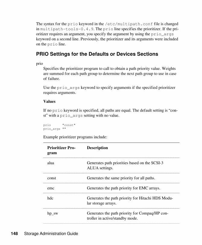
148 Storage Administration Guide
The syntax for the prio keyword in the /etc/multipath.conf file is changedin multipath-tools-0.4.9. The prio line specifies the prioritizer. If the pri-oritizer requires an argument, you specify the argument by using the prio_argskeyword on a second line. Previously, the prioritizer and its arguments were includedon the prio line.
PRIO Settings for the Defaults or Devices Sectionsprio
Specifies the prioritizer program to call to obtain a path priority value. Weightsare summed for each path group to determine the next path group to use in caseof failure.
Use the prio_args keyword to specify arguments if the specified prioritizerrequires arguments.
Values
If no prio keyword is specified, all paths are equal. The default setting is “con-st” with a prio_args setting with no value.
prio "const"prio_args ""
Example prioritizer programs include:
Prioritizer Pro-gram
Description
alua Generates path priorities based on the SCSI-3ALUA settings.
const Generates the same priority for all paths.
emc Generates the path priority for EMC arrays.
hdc Generates the path priority for Hitachi HDS Modu-lar storage arrays.
hp_sw Generates the path priority for Compaq/HP con-troller in active/standby mode.

Managing Multipath I/O for Devices 149
Prioritizer Pro-gram
Description
ontap Generates the path priority for NetApp arrays.
random Generates a random priority for each path.
rdac Generates the path priority for LSI/Engenio RDACcontroller.
weightedpath Generates the path priority based on the weight-ed values you specify in the arguments forprio_args, such as:
<hbtl|devname> <regex1> <prio1> <regex2> <prio2>...
The hbtl regex argument format uses theSCSI H:B:T:L notation (such as 1:0:.:. and*:0:0:.) with a weight value, where H, B, T, Lare the host, bus, target, and LUN IDs for a device.For example:
prio "weightedpath"prio_args "hbtl 1:.:.:. 2 4:.:.:. 4"
The devname regex argument format uses a devicenode name with a weight value for each device. Forexample:
prio "weightedpath"prio_args "devname sda 50 sde 10 sdc 50 sdf 10"
prio_argsSpecifies the arguments for the specified prioritizer program that requires argu-ments. Most prio programs do not need arguments.
Values
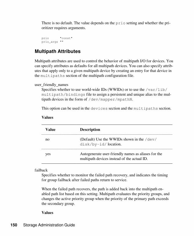
150 Storage Administration Guide
There is no default. The value depends on the prio setting and whether the pri-oritizer requires arguments.
prio "const"prio_args ""
Multipath Attributes
Multipath attributes are used to control the behavior of multipath I/O for devices. Youcan specify attributes as defaults for all multipath devices. You can also specify attrib-utes that apply only to a given multipath device by creating an entry for that device inthe multipaths section of the multipath configuration file.
user_friendly_namesSpecifies whether to use world-wide IDs (WWIDs) or to use the /var/lib/multipath/bindings file to assign a persistent and unique alias to the mul-tipath devices in the form of /dev/mapper/mpathN.
This option can be used in the devices section and the multipaths section.
Values
Value Description
no (Default) Use the WWIDs shown in the /dev/disk/by-id/ location.
yes Autogenerate user-friendly names as aliases for themultipath devices instead of the actual ID.
failbackSpecifies whether to monitor the failed path recovery, and indicates the timingfor group failback after failed paths return to service.
When the failed path recovers, the path is added back into the multipath en-abled path list based on this setting. Multipath evaluates the priority groups, andchanges the active priority group when the priority of the primary path exceedsthe secondary group.
Values

Managing Multipath I/O for Devices 151
Value Description
manual (Default) The failed path is not monitored for recov-ery. The administrator runs the multipath com-mand to update enabled paths and priority groups.
immediate When a path recovers, enable the path immediately.
n When the path recovers, wait n seconds before en-abling the path. Specify an integer value greater than 0.
We recommend failback setting of “manual” for multipath in cluster environ-ments in order to prevent multipath failover ping-pong.
failback "manual"
IMPORTANT
Ensure that you verify the failback setting with your storage system ven-dor. Different storage systems can require different settings.
getuid_calloutThe default program and arguments to call to obtain a unique path identifier.Specify the location with an absolute Linux path.
This attribute is deprecated in SLES 11 SP3 and later. It is replaced by theuid_attribute.
Values
The default location and arguments are:
/lib/udev/scsi_id -g -u -s
Example:
getuid_callout "/lib/udev/scsi_id -g -u -d /dev/%n"
getuid_callout "/lib/udev/scsi_id --whitelisted --device=/dev/%n"
no_path_retrySpecifies the behaviors to use on path failure.

152 Storage Administration Guide
Values
Value Description
n Specifies the number of retries until multipathstops the queuing and fails the path. Specify an integervalue greater than 0.
In a cluster, you can specify a value of “0” to preventqueuing and allow resources to fail over.
fail Specifies immediate failure (no queuing).
queue Never stop queuing (queue forever until the pathcomes alive).
We recommend a retry setting of “fail” or “0” in the /etc/multipath.conffile when working in a cluster. This causes the resources to fail over when theconnection is lost to storage. Otherwise, the messages queue and the resourcefailover cannot occur.
no_path_retry "fail"no_path_retry "0"
IMPORTANT
Ensure that you verify the retry settings with your storage system vendor.Different storage systems can require different settings.
path_checkerDetermines the state of the path.
Values
Value Description
directio (Default in multipath-tools version 0.4.8 andlater) Reads the first sector that has direct I/O. This isuseful for DASD devices. Logs failure messages in /var/log/messages.

Managing Multipath I/O for Devices 153
Value Description
readsector0 (Default in multipath-tools version 0.4.7 andearlier; deprecated and replaced by directio.)Reads the first sector of the device. Logs failure mes-sages in /var/log/messages.
tur Issues a SCSI test unit ready command to the device.This is the preferred setting if the LUN supports it. Onfailure, the command does not fill up /var/log/messages with messages.
custom_vendor_valueSome SAN vendors provide custom path_checker op-tions:
• cciss_tur: Checks the path state for HP Smart Stor-age Arrays.
• emc_clariion: Queries the EMC Clariion EVPDpage 0xC0 to determine the path state.
• hp_sw: Checks the path state (Up, Down, orGhost) for HP storage arrays with Active/Standbyfirmware.
• rdac: Checks the path state for the LSI/EngenioRDAC storage controller.
path_grouping_policySpecifies the path grouping policy for a multipath device hosted by a given con-troller.
Values
Value Description
failover (Default) One path is assigned per priority group sothat only one path at a time is used.

154 Storage Administration Guide
Value Description
multibus All valid paths are in one priority group. Traffic isload-balanced across all active paths in the group.
group_by_prio One priority group exists for each path priority value.Paths with the same priority are in the same prioritygroup. Priorities are assigned by an external program.
group_by_serial Paths are grouped by the SCSI target serial number(controller node WWN).
group_by_node_nameOne priority group is assigned per target node name.Target node names are fetched in /sys/class/fc_transport/target*/node_name.
path_selectorSpecifies the path-selector algorithm to use for load balancing.
Values
Value Description
round-robin 0 (Default in SLES 11 SP2 and earlier) The load-balanc-ing algorithm used to balance traffic across all activepaths in a priority group.
queue-length 0 A dynamic load balancer that balances the number ofin-flight I/O on paths similar to the least-pending op-tion.
service-time 0 (Default in SLES 11 SP3 and later) A service-time ori-ented load balancer that balances I/O on paths accord-ing to the latency.
pg_timeoutSpecifies path group timeout handling.
Values

Managing Multipath I/O for Devices 155
NONE (internal default)
polling_intervalSpecifies the time in seconds between the end of one path checking cycle and thebeginning of the next path checking cycle.
Values
Specify an integer value greater than 0. The default value is 5. Ensure that youverify the polling_interval setting with your storage system vendor. Differentstorage systems can require different settings.
prio_calloutSpecifies the program and arguments to use to determine the layout of the multi-path map.
Multipath prio_callout programs are located in shared libraries in /lib/libmultipath/lib*. By using shared libraries, the callout programs are loadedinto memory on daemon startup.
When queried by the multipath command, the specified mpath_prio_* call-out program returns the priority for a given path in relation to the entire multipathlayout.
When it is used with the path_grouping_policy of group_by_prio, all paths withthe same priority are grouped into one multipath group. The group with the high-est aggregate priority becomes the active group.
When all paths in a group fail, the group with the next highest aggregate priori-ty becomes active. Additionally, a failover command (as determined by the hard-ware handler) might be send to the target.
The mpath_prio_* program can also be a custom script created by a vendor or ad-ministrator for a specified setup.
• A %n in the command line expands to the device name in the /dev direc-tory.
• A %b in the command line expands to the device number inmajor:minor format in the /dev directory.
• A %d in the command line expands to the device ID in the /dev/disk/by-id directory.

156 Storage Administration Guide
If devices are hot-pluggable, use the %d flag instead of %n. This addresses theshort time that elapses between the time when devices are available and whenudev creates the device nodes.
Values
Value Description
(No value) If no prio_callout attribute is used, all paths areequal. This is the default.
/bin/true Specify this value when the group_by_prio is not beingused.
The prioritizer programs generate path priorities when queried by themultipath command. The program names must begin with mpath_prio_and are named by the device type or balancing method used. Current prioritizerprograms include the following:
Prioritizer Program Description
mpath_prio_alua %n Generates path priorities based on the SCSI-3ALUA settings.
mpath_prio_balance_units Generates the same priority for all paths.
mpath_prio_emc %n Generates the path priority for EMC arrays.
mpath_prio_hds_modular%b
Generates the path priority for Hitachi HDSModular storage arrays.
mpath_prio_hp_sw %n Generates the path priority for Compaq/HPcontroller in active/standby mode.
mpath_prio_netapp %n Generates the path priority for NetApp arrays.
mpath_prio_random%n
Generates a random priority for each path.

Managing Multipath I/O for Devices 157
Prioritizer Program Description
mpath_prio_rdac %n Generates the path priority for LSI/EngenioRDAC controller.
mpath_prio_tpc %n You can optionally use a script created by avendor or administrator that gets the prioritiesfrom a file where you specify priorities to usefor each path.
mpath_prio_spec.sh %n Provides the path of a user-created script thatgenerates the priorities for multipathing basedon information contained in a second data file.(This path and filename are provided as an ex-ample. Specify the location of your script in-stead.) The script can be created by a vendor oradministrator. The script’s target file identifieseach path for all multipathed devices and spec-ifies a priority for each path. For an example,see Section 7.11.3, “Using a Script to Set PathPriorities” (page 159).
rr_min_ioSpecifies the number of I/O transactions to route to a path before switching to thenext path in the same path group, as determined by the specified algorithm in thepath_selector setting.
The rr_min_io attribute is used only for kernels 2.6.31 and earlier. It is obsoletedin SLES 11 SP2 and replaced by the rr_min_io_rq attribute.
Values
Specify an integer value greater than 0. The default value is 1000.
rr_min_io "1000"
rr_min_io_rqSpecifies the number of I/O requests to route to a path before switching to thenext path in the current path group, using request-based device-mapper-multi-path.

158 Storage Administration Guide
This attribute is available for systems running SLES 11 SP2 and later. It replacesthe rr_min_io attribute.
Values
Specify an integer value greater than 0. The default value is 1.
rr_min_io_rq "1"
rr_weightSpecifies the weighting method to use for paths.
Values
Value Description
uniform (Default) All paths have the same round-robin weights.
priorities Each path’s weight is determined by the path’s priori-ty times the rr_min_io_rq setting (or the rr_min_io set-ting for kernels 2.6.31 and earlier).
uid_attributeA udev attribute that provides a unique path identifier. The default value isID_SERIAL.
7.11.2.2 Configuring for Round-Robin LoadBalancingAll paths are active. I/O is configured for some number of seconds or some numberof I/O transactions before moving to the next open path in the sequence.
7.11.2.3 Configuring for Single Path FailoverA single path with the highest priority (lowest value setting) is active for traffic. Otherpaths are available for failover, but are not used unless failover occurs.

Managing Multipath I/O for Devices 159
7.11.2.4 Grouping I/O Paths for Round-Robin LoadBalancingMultiple paths with the same priority fall into the active group. When all paths in thatgroup fail, the device fails over to the next highest priority group. All paths in thegroup share the traffic load in a round-robin load balancing fashion.
7.11.3 Using a Script to Set PathPrioritiesYou can create a script that interacts with Device Mapper Multipath (DM-MPIO) to provide priorities for paths to the LUN when set as a resource for theprio_callout setting.
First, set up a text file that lists information about each device and the priority valuesyou want to assign to each path. For example, name the file /usr/local/etc/primary-paths. Enter one line for each path in the following format:
host_wwpn target_wwpn scsi_id priority_value
Return a priority value for each path on the device. Ensure that the variableFILE_PRIMARY_PATHS resolves to a real file with appropriate data (host wwpn,target wwpn, scsi_id and priority value) for each device.
The contents of the primary-paths file for a single LUN with eight paths eachmight look like this:
0x10000000c95ebeb4 0x200200a0b8122c6e 2:0:0:0 sdb 3600a0b8000122c6d00000000453174fc 50
0x10000000c95ebeb4 0x200200a0b8122c6e 2:0:0:1 sdc 3600a0b80000fd6320000000045317563 2
0x10000000c95ebeb4 0x200200a0b8122c6e 2:0:0:2 sdd 3600a0b8000122c6d0000000345317524 50
0x10000000c95ebeb4 0x200200a0b8122c6e 2:0:0:3 sde 3600a0b80000fd6320000000245317593 2
0x10000000c95ebeb4 0x200300a0b8122c6e 2:0:1:0 sdi 3600a0b8000122c6d00000000453174fc 5

160 Storage Administration Guide
0x10000000c95ebeb4 0x200300a0b8122c6e 2:0:1:1 sdj 3600a0b80000fd6320000000045317563 51
0x10000000c95ebeb4 0x200300a0b8122c6e 2:0:1:2 sdk 3600a0b8000122c6d0000000345317524 5
0x10000000c95ebeb4 0x200300a0b8122c6e 2:0:1:3 sdl 3600a0b80000fd6320000000245317593 51
To continue the example mentioned in “prio_callout” (page 155), create a scriptnamed /usr/local/sbin/path_prio.sh. You can use any path and file-name. The script does the following:
• On query from multipath, grep the device and its path from the /usr/local/etc/primary-paths file.
• Return to multipath the priority value in the last column for that entry in the file.
7.11.4 Configuring ALUA(mpath_prio_alua)The mpath_prio_alua(8) command is used as a priority callout for the Lin-ux multipath(8) command. It returns a number that is used by DM-MPIO togroup SCSI devices with the same priority together. This path priority tool is based onALUA (Asynchronous Logical Unit Access).
• Section 7.11.4.1, “Syntax” (page 160)
• Section 7.11.4.2, “Prerequisite” (page 160)
• Section 7.11.4.3, “Options” (page 161)
• Section 7.11.4.4, “Return Values” (page 161)
7.11.4.1 Syntaxmpath_prio_alua [-d directory] [-h] [-v] [-V] device [device...]
7.11.4.2 PrerequisiteSCSI devices.

Managing Multipath I/O for Devices 161
7.11.4.3 Options-d directory
Specifies the Linux directory path where the listed device node names can befound. The default directory is /dev. When you use this option, specify the de-vice node name only (such as sda) for the device or devices you want to manage.
-hDisplays help for this command, then exits.
-vTurns on verbose output to display status in human-readable format. Output in-cludes information about which port group the specified device is in and its cur-rent state.
-VDisplays the version number of this tool, then exits.
device [device...]Specifies the SCSI device (or multiple devices) that you want to manage. Thedevice must be a SCSI device that supports the Report Target Port Groups(sg_rtpg(8)) command. Use one of the following formats for the device nodename:
• The full Linux directory path, such as /dev/sda. Do not use with the -doption.
• The device node name only, such as sda. Specify the directory path byusing the -d option.
• The major and minor number of the device separated by a colon (:) withno spaces, such as 8:0. This creates a temporary device node in the /devdirectory with a name in the format of tmpdev-<major>:<minor>-<pid>. For example, /dev/tmpdev-8:0-<pid>.
7.11.4.4 Return ValuesOn success, returns a value of 0 and the priority value for the group. Table 7.6,“ALUA Priorities for Device Mapper Multipath” (page 162) shows the priorityvalues returned by the mpath_prio_alua command.

162 Storage Administration Guide
Table 7.6: ALUA Priorities for Device Mapper Multipath
Priority Val-ue
Description
50 The device is in the active, optimized group.
10 The device is in an active but non-optimized group.
1 The device is in the standby group.
0 All other groups.
Values are widely spaced because of the way the multipath command handlesthem. It multiplies the number of paths in a group with the priority value for thegroup, then selects the group with the highest result. For example, if a non-optimizedpath group has six paths (6 x 10 = 60) and the optimized path group has a single path(1 x 50 = 50), the non-optimized group has the highest score, so multipath chooses thenon-optimized group. Traffic to the device uses all six paths in the group in a round-robin fashion.
On failure, returns a value of 1 to 5 indicating the cause for the command’s failure.For information, see the man page for mpath_prio_alua.
7.11.5 Reporting Target Path GroupsUse the SCSI Report Target Port Groups (sg_rtpg(8)) command. For informa-tion, see the man page for sg_rtpg(8).
7.12 Configuring Multipath I/O forthe Root DeviceDevice Mapper Multipath I/O (DM-MPIO) is available and supported for /boot and/root in SUSE Linux Enterprise Server 11. In addition, the YaST Partitioner in theYaST installer supports enabling multipath during the install.
• Section 7.12.1, “Enabling Multipath I/O at Install Time” (page 163)

Managing Multipath I/O for Devices 163
• Section 7.12.2, “Enabling Multipath I/O for an Existing Root Device” (page 166)
• Section 7.12.3, “Disabling Multipath I/O on the Root Device” (page 167)
7.12.1 Enabling Multipath I/O at InstallTimeThe multipath software must be running at install time if you want to install the oper-ating system on a multipath device. The multipathd daemon is not automatically ac-tive during the system installation. You can start it by using the Configure Multipathoption in the YaST Partitioner.
• Section 7.12.1.1, “Enabling Multipath I/O at Install Time on an Active/Active Mul-tipath Storage LUN” (page 163)
• Section 7.12.1.2, “Enabling Multipath I/O at Install Time on an Active/PassiveMultipath Storage LUN” (page 164)
7.12.1.1 Enabling Multipath I/O at Install Time onan Active/Active Multipath Storage LUN1 During the install on the YaST Installation Settings page, click on Partitioning to
open the YaST Partitioner.
2 Select Custom Partitioning (for experts).
3 Select the Hard Disks main icon, click the Configure button, then select ConfigureMultipath.
4 Start multipath.
YaST starts to rescan the disks and shows available multi-path devices (such as /dev/disk/by-id/dm-uuid-mpath-3600a0b80000f4593000012ae4ab0ae65). This is the device thatshould be used for all further processing.
5 Click Next to continue with the installation.

164 Storage Administration Guide
7.12.1.2 Enabling Multipath I/O at Install Time onan Active/Passive Multipath Storage LUNThe multipathd daemon is not automatically active during the system installation. Youcan start it by using the Configure Multipath option in the YaST Partitioner.
To enable multipath I/O at install time for an active/passive multipath storage LUN:
1 During the install on the YaST Installation Settings page, click on Partitioning toopen the YaST Partitioner.
2 Select Custom Partitioning (for experts).
3 Select the Hard Disks main icon, click the Configure button, then select Config-ure Multipath.
4 Start multipath.
YaST starts to rescan the disks and shows available multi-path devices (such as /dev/disk/by-id/dm-uuid-mpath-3600a0b80000f4593000012ae4ab0ae65). This is the devicethat should be used for all further processing. Write down the device path andUUID; you need it later.
5 Click Next to continue with the installation.
6 After all settings are done and the installation finished, YaST starts to write theboot loader information, and displays a countdown to restart the system. Stopthe counter by clicking the Stop button and press CTRL+ALT+F5 to access aconsole.
7 Use the console to determine if a passive path was entered in the /boot/grub/device.map file for the hd0 entry.
This is necessary because the installation does not distinguish between activeand passive paths.
7a Mount the root device to /mnt by entering
mount /dev/disk/by-id/<UUID>_part2 /mnt
For example, enter

Managing Multipath I/O for Devices 165
mount /dev/disk/by-id/dm-uuid-mpath-3600a0b80000f4593000012ae4ab0ae65_part2 /mnt
7b Mount the boot device to /mnt/boot by entering
mount /dev/disk/by-id/<UUID>_part1 /mnt/boot
For example, enter
mount /dev/disk/by-id/dm-uuid-mpath-3600a0b80000f4593000012ae4ab0ae65_part2 /mnt/boot
7c Open /mnt/boot/grub/device.map file by entering
less /mnt/boot/grub/device.map
7d In the /mnt/boot/grub/device.map file, determine if the hd0entry points to a passive path, then do one of the following:
• Active path: No action is needed; skip Step 8 (page 165) and con-tinue with Step 9 (page 166).
• Passive path: The configuration must be changed and the boot loadermust be reinstalled. Continue with Step 8 (page 165).
8 If the hd0 entry points to a passive path, change the configuration and reinstallthe boot loader:
8a At the console, enter the following commands at the console prompt:
mount -o bind /dev /mnt/dev
mount -o bind /sys /mnt/sys
mount -o bind /proc /mnt/proc
chroot
8b At the console, run multipath -ll, then check the output to find theactive path.
Passive paths are flagged as ghost.

166 Storage Administration Guide
8c In the /mnt/boot/grub/device.map file, change the hd0 entryto an active path, save the changes, and close the file.
8d In case the selection was to boot from MBR, /etc/grub.confshould look like the following:
setup --stage2=/boot/grub/stage2 (hd0) (hd0,0)quit
8e Reinstall the boot loader by entering
grub < /etc/grub.conf
8f Enter the following commands:
exit
umount /mnt/*
umount /mnt
9 Return to the YaST graphical environment by pressing CTRL+ALT+F7.
10 Click OK to continue with the installation reboot.
7.12.2 Enabling Multipath I/O for anExisting Root Device1 Install Linux with only a single path active, preferably one where the by-id sym-
links are listed in the partitioner.
2 Mount the devices by using the /dev/disk/by-id path used during the install.
3 After installation, add dm-multipath to /etc/sysconfig/kernel:INITRD_MODULES.
4 For System Z, before running mkinitrd, edit the /etc/zipl.conf file tochange the by-path information in zipl.conf with the same by-id informationthat was used in the /etc/fstab.
5 Re-run /sbin/mkinitrd to update the initrd image.

Managing Multipath I/O for Devices 167
6 For System Z, after running mkinitrd, run zipl.
7 Reboot the server.
7.12.3 Disabling Multipath I/O on the RootDevice• Add multipath=off to the kernel command line.
This affects only the root device. All other devices are not affected.
7.13 Configuring Multipath I/O foran Existing Software RAIDIdeally, you should configure multipathing for devices before you use them as compo-nents of a software RAID device. If you add multipathing after creating any softwareRAID devices, the DM-MPIO service might be starting after the multipath ser-vice on reboot, which makes multipathing appear not to be available for RAIDs. Youcan use the procedure in this section to get multipathing running for a previously ex-isting software RAID.
For example, you might need to configure multipathing for devices in a softwareRAID under the following circumstances:
• If you create a new software RAID as part of the Partitioning settings during a newinstall or upgrade.
• If you did not configure the devices for multipathing before using them in the soft-ware RAID as a member device or spare.
• If you grow your system by adding new HBA adapters to the server or expandingthe storage subsystem in your SAN.
NOTE
The following instructions assume the software RAID device is /dev/mapper/mpath0>, which is its device name as recognized by the ker-nel. It assumes you have enabled user-friendly-names in the /etc/

168 Storage Administration Guide
multipath.conf file as described in Section 7.9, “Configuring User-Friendly Names or Alias Names” (page 140).
Ensure that you modify the instructions for the device name of your softwareRAID.
1 Open a terminal console, then log in as the root user or equivalent.
Except where otherwise directed, use this console to enter the commands in thefollowing steps.
2 If any software RAID devices are currently mounted or running, enter the fol-lowing commands for each device to dismount the device and stop it.
umount /dev/mapper/mpath0
mdadm --misc --stop /dev/mapper/mpath0
3 Stop the boot.md service by entering
/etc/init.d/boot.md stop
4 Start the boot.multipath and multipathd services by entering the fol-lowing commands:
/etc/init.d/boot.multipath start
/etc/init.s/multipathd start
5 After the multipathing services are started, verify that the software RAID’scomponent devices are listed in the /dev/disk/by-id directory. Do one ofthe following:
• Devices Are Listed: The device names should now have symbolic links totheir Device Mapper Multipath device names, such as /dev/dm-1.
• Devices Are Not Listed: Force the multipath service to recognize them byflushing and rediscovering the devices.
To do this, enter the following commands:
multipath -F

Managing Multipath I/O for Devices 169
multipath -v0
The devices should now be listed in /dev/disk/by-id, and have symbol-ic links to their Device Mapper Multipath device names. For example:
lrwxrwxrwx 1 root root 10 2011-01-06 11:42 dm-uuid-mpath-36006016088d014007e0d0d2213ecdf11 -> ../../dm-1
6 Restart the boot.md service and the RAID device by entering
/etc/init.d/boot.md start
7 Check the status of the software RAID by entering
mdadm --detail /dev/mapper/mpath0
The RAID’s component devices should match their Device Mapper Multipathdevice names that are listed as the symbolic links of devices in the /dev/disk/by-id directory.
8 Make a new initrd to ensure that the Device Mapper Multipath services areloaded before the RAID services on reboot. Running mkinitrd is needed onlyif the root (/) device or any parts of it (such as /var, /etc, /log) are on theSAN and multipath is needed to boot.
Enter
mkinitrd -f multipath
9 Reboot the server to apply these post-install configuration settings.
10 Verify that the software RAID array comes up properly on top of the multi-pathed devices by checking the RAID status. Enter
mdadm --detail /dev/mapper/mpath0
For example:
Number Major Minor RaidDevice State0 253 0 0 active sync /dev/dm-01 253 1 1 active sync /dev/dm-1

170 Storage Administration Guide
2 253 2 2 active sync /dev/dm-2
7.14 Scanning for New Deviceswithout RebootingIf your system has already been configured for multipathing and you later need to addmore storage to the SAN, you can use the rescan-scsi-bus.sh script to scanfor the new devices. By default, this script scans all HBAs with typical LUN ranges.
WARNING
In EMC PowerPath environments, do not use the rescan-scsi-bus.shutility provided with the operating system or the HBA vendor scripts for scan-ning the SCSI buses. To avoid potential file system corruption, EMC requiresthat you follow the procedure provided in the vendor documentation for EMCPowerPath for Linux.
Syntaxrescan-scsi-bus.sh [options] [host [host ...]]
You can specify hosts on the command line (deprecated), or use the --hosts=LIST option (recommended).
OptionsFor most storage subsystems, the script can be run successfully without options. How-ever, some special cases might need to use one or more of the following parametersfor the rescan-scsi-bus.sh script:
Option Description
-lActivates scanning for LUNs 0-7. [Default: 0]
-L NUMActivates scanning for LUNs 0 to NUM. [Default: 0]

Managing Multipath I/O for Devices 171
Option Description
-wScans for target device IDs 0 to 15. [Default: 0 to 7]
-cEnables scanning of channels 0 or 1. [Default: 0]
-r--remove
Enables removing of devices. [Default: Disabled]
-i--issueLip
Issues a Fibre Channel LIP reset. [Default: Disabled]
--forcerescanRescans existing devices.
--forceremoveRemoves and re-adds every device.
WARNING
Use with caution, this option is dangerous.
--nooptscanDon’t stop looking for LUNs if 0 is not found.
--colorUse colored prefixes OLD/NEW/DEL.
--hosts=LISTScans only hosts in LIST, where LIST is a comma-separat-ed list of single values and ranges. No spaces are allowed.
--hosts=A[-B][,C[-D]]
--channels=LIST
Scans only channels in LIST, where LIST is a comma-sep-arated list of single values and ranges. No spaces are al-lowed.
--channels=A[-B][,C[-D]]
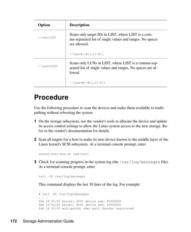
172 Storage Administration Guide
Option Description
--ids=LISTScans only target IDs in LIST, where LIST is a com-ma-separated list of single values and ranges. No spacesare allowed.
--ids=A[-B][,C[-D]]
--luns=LISTScans only LUNs in LIST, where LIST is a comma-sep-arated list of single values and ranges. No spaces are al-lowed.
--luns=A[-B][,C[-D]]
ProcedureUse the following procedure to scan the devices and make them available to multi-pathing without rebooting the system.
1 On the storage subsystem, use the vendor’s tools to allocate the device and updateits access control settings to allow the Linux system access to the new storage. Re-fer to the vendor’s documentation for details.
2 Scan all targets for a host to make its new device known to the middle layer of theLinux kernel’s SCSI subsystem. At a terminal console prompt, enter
rescan-scsi-bus.sh [options]
3 Check for scanning progress in the system log (the /var/log/messages file).At a terminal console prompt, enter
tail -30 /var/log/messages
This command displays the last 30 lines of the log. For example:
# tail -30 /var/log/messages. . .Feb 14 01:03 kernel: SCSI device sde: 81920000Feb 14 01:03 kernel: SCSI device sdf: 81920000Feb 14 01:03 multipathd: sde: path checker registered

Managing Multipath I/O for Devices 173
Feb 14 01:03 multipathd: sdf: path checker registeredFeb 14 01:03 multipathd: mpath4: event checker startedFeb 14 01:03 multipathd: mpath5: event checker startedFeb 14 01:03:multipathd: mpath4: remaining active paths: 1Feb 14 01:03 multipathd: mpath5: remaining active paths: 1
4 Repeat Step 2 (page 172) through Step 3 (page 172) to add paths through oth-er HBA adapters on the Linux system that are connected to the new device.
5 Run the multipath command to recognize the devices for DM-MPIO configu-ration. At a terminal console prompt, enter
multipath
You can now configure the new device for multipathing.
7.15 Scanning for New PartitionedDevices without RebootingUse the example in this section to detect a newly added multipathed LUN without re-booting.
WARNING
In EMC PowerPath environments, do not use the rescan-scsi-bus.shutility provided with the operating system or the HBA vendor scripts for scan-ning the SCSI buses. To avoid potential file system corruption, EMC requiresthat you follow the procedure provided in the vendor documentation for EMCPowerPath for Linux.
1 Open a terminal console, then log in as the root user.
2 Scan all targets for a host to make its new device known to the middle layer ofthe Linux kernel’s SCSI subsystem. At a terminal console prompt, enter
rescan-scsi-bus.sh [options]
For syntax and options information for the rescan-scsi-bus-sh script,see Section 7.14, “Scanning for New Devices without Rebooting” (page 170).

174 Storage Administration Guide
3 Verify that the device is seen (such as if the link has a new time stamp) by en-tering
ls -lrt /dev/dm-*
You can also verify the devices in /dev/disk/by-id by entering
ls -l /dev/disk/by-id/
4 Verify the new device appears in the log by entering
tail -33 /var/log/messages
5 Use a text editor to add a new alias definition for the device in the /etc/multipath.conf file, such as data_vol3.
For example, if the UUID is 36006016088d014006e98a7a94a85db11,make the following changes:
defaults { user_friendly_names yes }multipaths { multipath { wwid 36006016088d014006e98a7a94a85db11 alias data_vol3 } }
6 Create a partition table for the device by entering
fdisk /dev/disk/by-id/dm-uuid-mpath-<UUID>
Replace UUID with the device WWID, such as36006016088d014006e98a7a94a85db11.
7 Trigger udev by entering
echo 'add' > /sys/block/<dm_device>/uevent
For example, to generate the device-mapper devices for the partitions on dm-8,enter

Managing Multipath I/O for Devices 175
echo 'add' > /sys/block/dm-8/uevent
8 Create a file system and label for the new partition by entering the followingcommands:
mke2fs -j /dev/disk/by-id/dm-uuid-mpath-<UUID_partN>tune2fs -L data_vol3 /dev/disk/by-id/dm-uuid-<UUID_partN>
Replace UUID_part1 with the actual UUID and partition number, such as36006016088d014006e98a7a94a85db11_part1.
9 Restart DM-MPIO to let it read the aliases by entering
/etc/init.d/multipathd restart
10 Verify that the device is recognized by multipathd by entering
multipath -ll
11 Use a text editor to add a mount entry in the /etc/fstab file.
At this point, the alias you created in Step 5 (page 174) is not yet in the /dev/disk/by-label directory. Add the mount entry the /dev/dm-9path, then change the entry before the next time you reboot to
LABEL=data_vol3
12 Create a directory to use as the mount point, then mount the device by entering
md /data_vol3
mount /data_vol3
7.16 Viewing Multipath I/O StatusQuerying the multipath I/O status outputs the current status of the multipath maps.
The multipath -l option displays the current path status as of the last time thatthe path checker was run. It does not run the path checker.

176 Storage Administration Guide
The multipath -ll option runs the path checker, updates the path information,then displays the current status information. This option always the displays the latestinformation about the path status.
• At a terminal console prompt, enter
multipath -ll
This displays information for each multipathed device. For example:
3600601607cf30e00184589a37a31d911[size=127 GB][features="0"][hwhandler="1 emc"]
\_ round-robin 0 [active][first] \_ 1:0:1:2 sdav 66:240 [ready ][active] \_ 0:0:1:2 sdr 65:16 [ready ][active]
\_ round-robin 0 [enabled] \_ 1:0:0:2 sdag 66:0 [ready ][active] \_ 0:0:0:2 sdc 8:32 [ready ][active]
For each device, it shows the device’s ID, size, features, and hardware handlers.
Paths to the device are automatically grouped into priority groups on device discov-ery. Only one priority group is active at a time. For an active/active configuration, allpaths are in the same group. For an active/passive configuration, the passive paths areplaced in separate priority groups.
The following information is displayed for each group:
• Scheduling policy used to balance I/O within the group, such as round-robin
• Whether the group is active, disabled, or enabled
• Whether the group is the first (highest priority) group
• Paths contained within the group
The following information is displayed for each path:
• The physical address as host:bus:target:lun, such as 1:0:1:2
• Device node name, such as sda

Managing Multipath I/O for Devices 177
• Major:minor numbers
• Status of the device
7.17 Managing I/O in ErrorSituationsYou might need to configure multipathing to queue I/O if all paths fail concurrentlyby enabling queue_if_no_path. Otherwise, I/O fails immediately if all paths are gone.In certain scenarios, where the driver, the HBA, or the fabric experience spurious er-rors, DM-MPIO should be configured to queue all I/O where those errors lead to aloss of all paths, and never propagate errors upward.
When you use multipathed devices in a cluster, you might choose to disablequeue_if_no_path. This automatically fails the path instead of queuing the I/O, andescalates the I/O error to cause a failover of the cluster resources.
Because enabling queue_if_no_path leads to I/O being queued indefinitely unless apath is reinstated, ensure that multipathd is running and works for your scenario.Otherwise, I/O might be stalled indefinitely on the affected multipathed device untilreboot or until you manually return to failover instead of queuing.
To test the scenario:
1 In a terminal console, log in as the root user.
2 Activate queuing instead of failover for the device I/O by entering:
dmsetup message device_ID 0 queue_if_no_path
Replace the device_ID with the ID for your device. The 0 value represents thesector and is used when sector information is not needed.
For example, enter:
dmsetup message 3600601607cf30e00184589a37a31d911 0 queue_if_no_path
3 Return to failover for the device I/O by entering:
dmsetup message device_ID 0 fail_if_no_path

178 Storage Administration Guide
This command immediately causes all queued I/O to fail.
Replace the device_ID with the ID for your device. For example, enter:
dmsetup message 3600601607cf30e00184589a37a31d911 0 fail_if_no_path
To set up queuing I/O for scenarios where all paths fail:
1 In a terminal console, log in as the root user.
2 Open the /etc/multipath.conf file in a text editor.
3 Uncomment the defaults section and its ending bracket, then add thedefault_features setting, as follows:
defaults { default_features "1 queue_if_no_path"}
4 After you modify the /etc/multipath.conf file, you must run mkinitrdto re-create the initrd on your system, then reboot in order for the changes totake effect.
5 When you are ready to return over to failover for the device I/O, enter:
dmsetup message mapname 0 fail_if_no_path
Replace the mapname with the mapped alias name or the device ID for the device.The 0 value represents the sector and is used when sector information is not need-ed.
This command immediately causes all queued I/O to fail and propagates the errorto the calling application.
7.18 Resolving Stalled I/OIf all paths fail concurrently and I/O is queued and stalled, do the following:
1 Enter the following command at a terminal console prompt:

Managing Multipath I/O for Devices 179
dmsetup message mapname 0 fail_if_no_path
Replace mapname with the correct device ID or mapped alias name for the de-vice. The 0 value represents the sector and is used when sector information is notneeded.
This command immediately causes all queued I/O to fail and propagates the errorto the calling application.
2 Reactivate queueing by entering the following command at a terminal consoleprompt:
dmsetup message mapname 0 queue_if_no_path
7.19 Troubleshooting MPIOThis section describes some known issues and possible solutions for MPIO.
• Section 7.19.1, “PRIO Settings for Individual Devices Fail After Upgrading to Mul-tipath 0.4.9” (page 179)
• Section 7.19.2, “PRIO Settings with Arguments Fail After Upgrading to multi-path-tools-0.4.9” (page 180)
• Section 7.19.3, “Technical Information Documents” (page 180)
7.19.1 PRIO Settings for IndividualDevices Fail After Upgrading to Multipath0.4.9Multipath Tools 0.4.9 for SLES 11 SP2 uses the prio setting in the defaults{}or devices{} section of the /etc/multipath.conf file. It silently ignores thekeyword prio when it is specified for an individual multipath definition in themultipaths{) section.
Multipath Tools 0.4.8 for SLES 11 SP1 and earlier allows the prio setting in the indi-vidual multipath definition in the multipaths{) section to override the priosettings in the defaults{} or devices{} section.

180 Storage Administration Guide
7.19.2 PRIO Settings with Arguments FailAfter Upgrading to multipath-tools-0.4.9When you upgrade from multipath-tools-0.4.8 to multipath-tools-0.4.9, the prio settings in the /etc/multipath.conf fileare broken for prioritizers that require an argument. In multipath-tools-0.4.9, theprio keyword is used to specify the prioritizer, and the prio_args keyword isused to specify the argument for prioritizers that require an argument. Previously,both the prioritizer and its argument were specified on the same prio line.
For example, in multipath-tools-0.4.8, the following line was used to specify a priori-tizer and its arguments on the same line.
prio "weightedpath hbtl [1,3]:.:.+:.+ 260 [0,2]:.:.+:.+ 20"
After upgrading to multipath-tools-0.4.9, the command causes an error.The message is similar to the following:
<Month day hh:mm:ss> | Prioritizer 'weightedpath hbtl [1,3]:.:.+:.+ 260[0,2]:.:.+:.+ 20' not found in /lib64/multipath
To resolve this problem, use a text editor to modify the prio line in the /etc/multipath.conf file. Create two lines with the prioritizer specified on the prioline, and the prioritizer argument specified on the prio_args line below it:
prio "weightedpath"prio_args "hbtl [1,3]:.:.+:.+ 260 [0,2]:.:.+:.+ 20"
7.19.3 Technical Information DocumentsFor information about troubleshooting multipath I/O issues on SUSE Linux Enter-prise Server, see the following Technical Information Documents (TIDs) in the NovellSupport Knowledgebase:
• Troubleshooting SLES Multipathing (MPIO) Problems (TID 3231766) [ http://www.novell.com/support/kb/doc.php?id=3231766 ]
• DM MPIO Device Blacklisting Not Honored in multipath.conf (TID 3029706) [ http://www.novell.com/support/kb/doc.php?id=3029706 ]

Managing Multipath I/O for Devices 181
• Troubleshooting SCSI (LUN) Scanning Issues (TID 3955167) [ http://www.novell.com/support/kb/doc.php?id=3955167 ]
• Using LVM on Multipath (DM MPIO) Devices [ http://www.novell.com/support/kb/doc.php?id=7007498 ]
7.20 What’s NextIf you want to use software RAIDs, create and configure them before you create filesystems on the devices. For information, see the following:
• Chapter 8, Software RAID Configuration (page 183)
• Chapter 10, Managing Software RAIDs 6 and 10 with mdadm (page 199)


Software RAID Configuration 183
Software RAIDConfiguration 8The purpose of RAID (redundant array of independent disks) is to combine severalhard disk partitions into one large virtual hard disk to optimize performance, data se-curity, or both. Most RAID controllers use the SCSI protocol because it can addressa larger number of hard disks in a more effective way than the IDE protocol and ismore suitable for parallel processing of commands. There are some RAID controllersthat support IDE or SATA hard disks. Software RAID provides the advantages ofRAID systems without the additional cost of hardware RAID controllers. However,this requires some CPU time and has memory requirements that make it unsuitablefor real high performance computers.
IMPORTANT
Software RAID is not supported underneath clustered file systems such asOCFS2, because RAID does not support concurrent activation. If you wantRAID for OCFS2, you need the RAID to be handled by the storage subsys-tem.
SUSE Linux Enterprise offers the option of combining several hard disks into onesoft RAID system. RAID implies several strategies for combining several hard disksin a RAID system, each with different goals, advantages, and characteristics. Thesevariations are commonly known as RAID levels.
• Section 8.1, “Understanding RAID Levels” (page 184)
• Section 8.2, “Soft RAID Configuration with YaST” (page 186)
• Section 8.3, “Troubleshooting Software RAIDs” (page 188)

184 Storage Administration Guide
• Section 8.4, “For More Information” (page 189)
8.1 Understanding RAID LevelsThis section describes common RAID levels 0, 1, 2, 3, 4, 5, and nested RAID levels.
• Section 8.1.1, “RAID 0” (page 184)
• Section 8.1.2, “RAID 1” (page 184)
• Section 8.1.3, “RAID 2 and RAID 3” (page 185)
• Section 8.1.4, “RAID 4” (page 185)
• Section 8.1.5, “RAID 5” (page 185)
• Section 8.1.6, “Nested RAID Levels” (page 185)
8.1.1 RAID 0This level improves the performance of your data access by spreading out blocks ofeach file across multiple disk drives. Actually, this is not really a RAID, because itdoes not provide data backup, but the name RAID 0 for this type of system has be-come the norm. With RAID 0, two or more hard disks are pooled together. The per-formance is very good, but the RAID system is destroyed and your data lost if evenone hard disk fails.
8.1.2 RAID 1This level provides adequate security for your data, because the data is copied to an-other hard disk 1:1. This is known as hard disk mirroring. If a disk is destroyed, acopy of its contents is available on another mirrored disk. All disks except one couldbe damaged without endangering your data. However, if damage is not detected, dam-aged data might be mirrored to the correct disk and the data is corrupted that way.The writing performance suffers a little in the copying process compared to when us-ing single disk access (10 to 20 percent slower), but read access is significantly faster

Software RAID Configuration 185
in comparison to any one of the normal physical hard disks, because the data is dupli-cated so can be scanned in parallel. RAID 1 generally provides nearly twice the readtransaction rate of single disks and almost the same write transaction rate as singledisks.
8.1.3 RAID 2 and RAID 3These are not typical RAID implementations. Level 2 stripes data at the bit levelrather than the block level. Level 3 provides byte-level striping with a dedicated paritydisk and cannot service simultaneous multiple requests. Both levels are rarely used.
8.1.4 RAID 4Level 4 provides block-level striping just like Level 0 combined with a dedicated par-ity disk. If a data disk fails, the parity data is used to create a replacement disk. How-ever, the parity disk might create a bottleneck for write access. Nevertheless, Level 4is sometimes used.
8.1.5 RAID 5RAID 5 is an optimized compromise between Level 0 and Level 1 in terms of perfor-mance and redundancy. The hard disk space equals the number of disks used minusone. The data is distributed over the hard disks as with RAID 0. Parity blocks, creat-ed on one of the partitions, are there for security reasons. They are linked to each oth-er with XOR, enabling the contents to be reconstructed by the corresponding parityblock in case of system failure. With RAID 5, no more than one hard disk can fail atthe same time. If one hard disk fails, it must be replaced as soon as possible to avoidthe risk of losing data.
8.1.6 Nested RAID LevelsSeveral other RAID levels have been developed, such as RAIDn, RAID 10,RAID 0+1, RAID 30, and RAID 50. Some of them being proprietary implementa-tions created by hardware vendors. These levels are not very widespread, and are notexplained here.

186 Storage Administration Guide
8.2 Soft RAID Configuration withYaSTThe YaST soft RAID configuration can be reached from the YaST Expert Partitioner.This partitioning tool enables you to edit and delete existing partitions and create newones that should be used with soft RAID.
You can create RAID partitions by first clicking Create > Do not format then select-ing 0xFD Linux RAID as the partition identifier. For RAID 0 and RAID 1, at least twopartitions are needed—for RAID 1, usually exactly two and no more. If RAID 5 isused, at least three partitions are required. It is recommended to use only partitions ofthe same size because each segment can contribute only the same amount of space asthe smallest sized partition. The RAID partitions should be stored on different harddisks to decrease the risk of losing data if one is defective (RAID 1 and 5) and to op-timize the performance of RAID 0. After creating all the partitions to use with RAID,click RAID > Create RAID to start the RAID configuration.
On the next page of the wizard, choose among RAID levels 0, 1, and 5, then clickNext. The following dialog (see Figure 8.1, “RAID Partitions” (page 187)) lists allpartitions with either the Linux RAID or Linux native type. No swap or DOS partitionsare shown. If a partition is already assigned to a RAID volume, the name of the RAIDdevice (for example, /dev/md0) is shown in the list. Unassigned partitions are indi-cated with “--”.

Software RAID Configuration 187
Figure 8.1: RAID Partitions
To add a previously unassigned partition to the selected RAID volume, first select thepartition then click Add. At this point, the name of the RAID device is displayed nextto the selected partition. Assign all partitions reserved for RAID. Otherwise, the spaceon the partition remains unused. After assigning all partitions, click Next to proceedto the settings dialog where you can fine-tune the performance (see Figure 8.2, “FileSystem Settings” (page 188)).

188 Storage Administration Guide
Figure 8.2: File System Settings
As with conventional partitioning, set the file system to use as well as encryption andthe mount point for the RAID volume. After completing the configuration with Fin-ish, see the /dev/md0 device and others indicated with RAID in the Expert Parti-tioner.
8.3 Troubleshooting SoftwareRAIDsCheck the /proc/mdstat file to find out whether a RAID partition has been dam-aged. In the event of a system failure, shut down your Linux system and replace thedefective hard disk with a new one partitioned the same way. Then restart your sys-tem and enter the command mdadm /dev/mdX --add /dev/sdX. Replace Xwith your particular device identifiers. This integrates the hard disk automatically intothe RAID system and fully reconstructs it.

Software RAID Configuration 189
Although you can access all data during the rebuild, you might encounter some per-formance issues until the RAID has been fully rebuilt.
8.4 For More InformationConfiguration instructions and more details for soft RAID can be found in the HOW-TOs at:
• Linux RAID wiki [ https://raid.wiki.kernel.org/index.php/Linux_Raid ]
• The Software RAID HOWTO in the /usr/share/doc/packages/mdadm/Software-RAID.HOWTO.html file
Linux RAID mailing lists are also available, such as linux-raid [http://marc.info/?l=linux-raid].


Configuring Software RAID1 for the Root Partition 191
Configuring SoftwareRAID1 for the Root Partition 9In SUSE Linux Enterprise Server 11, the Device Mapper RAID tool has been inte-grated into the YaST Partitioner. You can use the partitioner at install time to createa software RAID1 for the system device that contains your root (/) partition. The /boot partition must be created on a separate device than the MD RAID1.
• Section 9.1, “Prerequisites for Using a Software RAID1 Device for the Root Parti-tion” (page 191)
• Section 9.2, “Enabling iSCSI Initiator Support at Install Time” (page 192)
• Section 9.3, “Enabling Multipath I/O Support at Install Time” (page 193)
• Section 9.4, “Creating a Software RAID1 Device for the Root (/) Partition” (page 193)
9.1 Prerequisites for Using aSoftware RAID1 Device for the RootPartitionEnsure that your configuration meets the following requirements:
• You need two hard drives to create the RAID1 mirror device. The hard drivesshould be similarly sized. The RAID assumes the size of the smaller drive. The

192 Storage Administration Guide
block storage devices can be any combination of local (in or directly attached to themachine), Fibre Channel storage subsystems, or iSCSI storage subsystems.
• You need a third device to use for the /bootpartition. The boot device should be alocal device.
• If you are using hardware RAID devices, do not attempt to run software RAIDs ontop of it.
• If you are using iSCSI target devices, you must enable the iSCSI initiator supportbefore you create the RAID device.
• If your storage subsystem provides multiple I/O paths between the server and its di-rectly attached local devices, Fibre Channel devices, or iSCSI devices that you wantto use in the software RAID, you must enable the multipath support before you cre-ate the RAID device.
9.2 Enabling iSCSI Initiator Supportat Install TimeIf there are iSCSI target devices that you want to use for the root (/) partition, youmust enable the iSCSI Initiator software to make those devices available to you beforeyou create the software RAID1 device.
1 Proceed with the YaST install of SUSE Linux Enterprise 11 until you reach the In-stallation Settings page.
2 Click Partitioning to open the Preparing Hard Disk page, click Custom Partitioning(for experts), then click Next.
3 On the Expert Partitioner page, expand Hard Disks in the System View panel toview the default proposal.
4 On the Hard Disks page, select ConfigureConfigure iSCSI, then click Continue whenprompted to continue with initializing the iSCSI initiator configuration.

Configuring Software RAID1 for the Root Partition 193
9.3 Enabling Multipath I/O Supportat Install TimeIf there are multiple I/O paths to the devices that you want to use for the root (/) par-tition, you must enable multipath support before you create the software RAID1 de-vice.
1 Proceed with the YaST install of SUSE Linux Enterprise 11 until you reach the In-stallation Settings page.
2 Click Partitioning to open the Preparing Hard Disk page, click Custom Partitioning(for experts), then click Next.
3 On the Expert Partitioner page, expand Hard Disks in the System View panel toview the default proposal.
4 On the Hard Disks page, select ConfigureConfigure Multipath, then click Yes whenprompted to activate multipath.
This re-scans the devices and resolves the multiple paths so that each device is list-ed only once in the list of hard disks.
9.4 Creating a Software RAID1Device for the Root (/) Partition1 Proceed with the YaST install of SUSE Linux Enterprise 11 until you reach the In-
stallation Settings page.
2 Click Partitioning to open the Preparing Hard Disk page, click Custom Partitioning(for experts), then click Next.
3 On the Expert Partitioner page, expand Hard Disks in the System View panel toview the default proposal, select the proposed partitions, then click Delete.
4 Create a /boot partition.
4a On the Expert Partitioner page under Hard Disks, select the device you wantto use for the /boot partition, then click Add on the Hard Disk Partitions tab.
194 Storage Administration Guide
4b Under New Partition Type, select Primary Partition, then click Next.
4c Under New Partition Size, specify the size to use, then click Next.
4d Under Format Options, select Format partition, then select your preferredfile system type (such as Ext2 or Ext3) from the drop-down list.
4e Under Mount Options, select Mount partition, then select /boot from thedrop-down list.
4f Click Finish.
5 Create a swap partition.
5a On the Expert Partitioner page under Hard Disks, select the device you wantto use for the swap partition, then click Add on the Hard Disk Partitions tab.
5b Under New Partition Type, select Primary Partition, then click Next.
5c Under New Partition Size, specify the size to use, then click Next.
5d Under Format Options, select Format partition, then select Swap from thedrop-down list.
5e Under Mount Options, select Mount partition, then select swap from thedrop-down list.
5f Click Finish.
6 Set up the 0xFD Linux RAID format for each of the devices you want to use for thesoftware RAID1.
6a On the Expert Partitioner page under Hard Disks, select the device you wantto use in the RAID1, then click Add on the Hard Disk Partitions tab.
6b Under New Partition Type, select Primary Partition, then click Next.
6c Under New Partition Size, specify to use the maximum size, then click Next.

Configuring Software RAID1 for the Root Partition 195
6d Under Format Options, select Do not format partition, then select 0xFD Lin-ux RAID from the drop-down list.
6e Under Mount Options, select Do not mount partition.
6f Click Finish.
6g Repeat Step 6a (page 194) to Step 6f (page 195) for each device thatyou plan to use in the software RAID1.
7 Create the RAID device.
7a In the System View panel, select RAID, then click Add RAID on the RAIDpage.
The devices that you prepared in Step 6 (page 194) are listed in AvailableDevices.
7b Under RAID Type, select RAID 1 (Mirroring).

196 Storage Administration Guide
7c In the Available Devices panel, select the devices you want to use for theRAID, then click Add to move the devices to the Selected Devices panel.
Specify two or more devices for a RAID1.
To continue the example, two devices are selected for RAID1.
7d Click Next.
7e Under RAID Options, select the chunk size from the drop-down list.
The default chunk size for a RAID1 (Mirroring) is 4 KB.
Available chunk sizes are 4 KB, 8 KB, 16 KB, 32 KB, 64 KB, 128 KB, 256KB, 512 KB, 1 MB, 2 MB, or 4 MB.
7f Under Formatting Options, select Format partition, then select the file sys-tem type (such as Ext3) from the File system drop-down list.

Configuring Software RAID1 for the Root Partition 197
7g Under Mounting Options, select Mount partition, then select /from theMount Point drop-down list.
7h Click Finish.
The software RAID device is managed by Device Mapper, and creates a de-vice under the /dev/md0 path.
8 On the Expert Partitioner page, click Accept.
The new proposal appears under Partitioning on the Installation Settings page.
For example, the setup for the
9 Continue with the install.

198 Storage Administration Guide
Whenever you reboot your server, Device Mapper is started at boot time so that thesoftware RAID is automatically recognized, and the operating system on the root(/) partition can be started.

Managing Software RAIDs 6 and 10 with mdadm 199
Managing Software RAIDs 6and 10 with mdadm 10This section describes how to create software RAID 6 and 10 devices, using the Mul-tiple Devices Administration (mdadm(8)) tool. You can also use mdadm to createRAIDs 0, 1, 4, and 5. The mdadm tool provides the functionality of legacy programsmdtools and raidtools.
• Section 10.1, “Creating a RAID 6” (page 199)
• Section 10.2, “Creating Nested RAID 10 Devices with mdadm” (page 201)
• Section 10.3, “Creating a Complex RAID 10” (page 206)
• Section 10.4, “Creating a Degraded RAID Array” (page 216)
10.1 Creating a RAID 6• Section 10.1.1, “Understanding RAID 6” (page 199)
• Section 10.1.2, “Creating a RAID 6” (page 200)
10.1.1 Understanding RAID 6RAID 6 is essentially an extension of RAID 5 that allows for additional fault toleranceby using a second independent distributed parity scheme (dual parity). Even if two ofthe hard disk drives fail during the data recovery process, the system continues to beoperational, with no data loss.

200 Storage Administration Guide
RAID 6 provides for extremely high data fault tolerance by sustaining multiple simul-taneous drive failures. It handles the loss of any two devices without data loss. Ac-cordingly, it requires N+2 drives to store N drives worth of data. It requires a mini-mum of 4 devices.
The performance for RAID 6 is slightly lower but comparable to RAID 5 in normalmode and single disk failure mode. It is very slow in dual disk failure mode.
Table 10.1: Comparison of RAID 5 and RAID 6
Feature RAID 5 RAID 6
Number of devices N+1, minimum of 3 N+2, minimum of 4
Parity Distributed, single Distributed, dual
Performance Medium impact onwrite and rebuild
More impact on se-quential write thanRAID 5
Fault-tolerance Failure of one compo-nent device
Failure of two compo-nent devices
10.1.2 Creating a RAID 6The procedure in this section creates a RAID 6 device /dev/md0 with four devices:/dev/sda1, /dev/sdb1, /dev/sdc1, and /dev/sdd1. Ensure that you modi-fy the procedure to use your actual device nodes.
1 Open a terminal console, then log in as the root user or equivalent.
2 Create a RAID 6 device. At the command prompt, enter
mdadm --create /dev/md0 --run --level=raid6 --chunk=128 --raid-devices=4 /dev/sdb1 /dev/sdc1 /dev/sdc1 /dev/sdd1
The default chunk size is 64 KB.
3 Create a file system on the RAID 6 device /dev/md0, such as a Reiser file sys-tem (reiserfs). For example, at the command prompt, enter

Managing Software RAIDs 6 and 10 with mdadm 201
mkfs.reiserfs /dev/md0
Modify the command if you want to use a different file system.
4 Edit the /etc/mdadm.conf file to add entries for the component devices andthe RAID device /dev/md0.
5 Edit the /etc/fstab file to add an entry for the RAID 6 device /dev/md0.
6 Reboot the server.
The RAID 6 device is mounted to /local.
7 (Optional) Add a hot spare to service the RAID array. For example, at the com-mand prompt enter:
mdadm /dev/md0 -a /dev/sde1
10.2 Creating Nested RAID 10Devices with mdadm• Section 10.2.1, “Understanding Nested RAID Devices” (page 201)
• Section 10.2.2, “Creating Nested RAID 10 (1+0) with mdadm” (page 203)
• Section 10.2.3, “Creating Nested RAID 10 (0+1) with mdadm” (page 204)
10.2.1 Understanding Nested RAIDDevicesA nested RAID device consists of a RAID array that uses another RAID array as itsbasic element, instead of using physical disks. The goal of this configuration is to im-prove the performance and fault tolerance of the RAID.
Linux supports nesting of RAID 1 (mirroring) and RAID 0 (striping) arrays. General-ly, this combination is referred to as RAID 10. To distinguish the order of the nesting,this document uses the following terminology:

202 Storage Administration Guide
• RAID 1+0: RAID 1 (mirror) arrays are built first, then combined to form a RAID0 (stripe) array.
• RAID 0+1: RAID 0 (stripe) arrays are built first, then combined to form a RAID1 (mirror) array.
The following table describes the advantages and disadvantages of RAID 10 nest-ing as 1+0 versus 0+1. It assumes that the storage objects you use reside on differentdisks, each with a dedicated I/O capability.
Table 10.2: Nested RAID Levels
RAIDLev-el
Descrip-tion
Performance and Fault Tolerance
10(1+0)
RAID 0(stripe)built withRAID 1(mirror)arrays
RAID 1+0 provides high levels of I/O performance,data redundancy, and disk fault tolerance. Becauseeach member device in the RAID 0 is mirrored indi-vidually, multiple disk failures can be tolerated anddata remains available as long as the disks that failare in different mirrors.
You can optionally configure a spare for each under-lying mirrored array, or configure a spare to serve aspare group that serves all mirrors.
10(0+1)
RAID 1(mirror)built withRAID 0(stripe) ar-rays
RAID 0+1 provides high levels of I/O performanceand data redundancy, but slightly less fault tolerancethan a 1+0. If multiple disks fail on one side of themirror, then the other mirror is available. Howev-er, if disks are lost concurrently on both sides of themirror, all data is lost.
This solution offers less disk fault tolerance thana 1+0 solution, but if you need to perform mainte-nance or maintain the mirror on a different site, youcan take an entire side of the mirror offline and stillhave a fully functional storage device. Also, if youlose the connection between the two sites, either siteoperates independently of the other. That is not true

Managing Software RAIDs 6 and 10 with mdadm 203
RAIDLev-el
Descrip-tion
Performance and Fault Tolerance
if you stripe the mirrored segments, because the mir-rors are managed at a lower level.
If a device fails, the mirror on that side fails becauseRAID 1 is not fault-tolerant. Create a new RAID0 to replace the failed side, then resynchronize themirrors.
10.2.2 Creating Nested RAID 10 (1+0) withmdadmA nested RAID 1+0 is built by creating two or more RAID 1 (mirror) devices, thenusing them as component devices in a RAID 0.
IMPORTANT
If you need to manage multiple connections to the devices, you must config-ure multipath I/O before configuring the RAID devices. For information, seeChapter 7, Managing Multipath I/O for Devices (page 95).
The procedure in this section uses the device names shown in the following table. En-sure that you modify the device names with the names of your own devices.
Table 10.3: Scenario for Creating a RAID 10 (1+0) by Nesting
Raw Devices RAID 1 (mirror) RAID 1+0 (stripedmirrors)
/dev/sdb1/dev/sdc1
/dev/md0
/dev/sdd1/dev/sde1
/dev/md1
/dev/md2

204 Storage Administration Guide
1 Open a terminal console, then log in as the root user or equivalent.
2 Create 2 software RAID 1 devices, using two different devices for each RAID 1device. At the command prompt, enter these two commands:
mdadm --create /dev/md0 --run --level=1 --raid-devices=2 /dev/sdb1 /dev/sdc1
mdadm --create /dev/md1 --run --level=1 --raid-devices=2 /dev/sdd1 /dev/sde1
3 Create the nested RAID 1+0 device. At the command prompt, enter the followingcommand using the software RAID 1 devices you created in Step 2 (page 204):
mdadm --create /dev/md2 --run --level=0 --chunk=64 --raid-devices=2 /dev/md0 /dev/md1
The default chunk size is 64 KB.
4 Create a file system on the RAID 1+0 device /dev/md2, such as a Reiser filesystem (reiserfs). For example, at the command prompt, enter
mkfs.reiserfs /dev/md2
Modify the command if you want to use a different file system.
5 Edit the /etc/mdadm.conf file to add entries for the component devices andthe RAID device /dev/md2.
6 Edit the /etc/fstab file to add an entry for the RAID 1+0 device /dev/md2.
7 Reboot the server.
The RAID 1+0 device is mounted to /local.
10.2.3 Creating Nested RAID 10 (0+1) withmdadmA nested RAID 0+1 is built by creating two to four RAID 0 (striping) devices, thenmirroring them as component devices in a RAID 1.

Managing Software RAIDs 6 and 10 with mdadm 205
IMPORTANT
If you need to manage multiple connections to the devices, you must config-ure multipath I/O before configuring the RAID devices. For information, seeChapter 7, Managing Multipath I/O for Devices (page 95).
In this configuration, spare devices cannot be specified for the underlying RAID 0 de-vices because RAID 0 cannot tolerate a device loss. If a device fails on one side of themirror, you must create a replacement RAID 0 device, than add it into the mirror.
The procedure in this section uses the device names shown in the following table. En-sure that you modify the device names with the names of your own devices.
Table 10.4: Scenario for Creating a RAID 10 (0+1) by Nesting
Raw Devices RAID 0 (stripe) RAID 0+1 (mirroredstripes)
/dev/sdb1/dev/sdc1
/dev/md0
/dev/sdd1/dev/sde1
/dev/md1
/dev/md2
1 Open a terminal console, then log in as the root user or equivalent.
2 Create two software RAID 0 devices, using two different devices for each RAID 0device. At the command prompt, enter these two commands:
mdadm --create /dev/md0 --run --level=0 --chunk=64 --raid-devices=2 /dev/sdb1 /dev/sdc1
mdadm --create /dev/md1 --run --level=0 --chunk=64 --raid-devices=2 /dev/sdd1 /dev/sde1
The default chunk size is 64 KB.
3 Create the nested RAID 0+1 device. At the command prompt, enter the followingcommand using the software RAID 0 devices you created in Step 2 (page 205):

206 Storage Administration Guide
mdadm --create /dev/md2 --run --level=1 --raid-devices=2 /dev/md0 /dev/md1
4 Create a file system on the RAID 0+1 device /dev/md2, such as a Reiser filesystem (reiserfs). For example, at the command prompt, enter
mkfs.reiserfs /dev/md2
Modify the command if you want to use a different file system.
5 Edit the /etc/mdadm.conf file to add entries for the component devices andthe RAID device /dev/md2.
6 Edit the /etc/fstab file to add an entry for the RAID 0+1 device /dev/md2.
7 Reboot the server.
The RAID 0+1 device is mounted to /local.
10.3 Creating a Complex RAID 10• Section 10.3.1, “Understanding the Complex RAID10” (page 206)
• Section 10.3.2, “Creating a Complex RAID 10 with mdadm” (page 210)
• Section 10.3.3, “Creating a Complex RAID10 with the YaST Partitioner” (page 212)
10.3.1 Understanding the ComplexRAID10In mdadm, the RAID10 level creates a single complex software RAID that combinesfeatures of both RAID 0 (striping) and RAID 1 (mirroring). Multiple copies of all da-ta blocks are arranged on multiple drives following a striping discipline. Componentdevices should be the same size.
• Section 10.3.1.1, “Comparing the Complex RAID10 and Nested RAID 10 (1+0)” (page 207)
• Section 10.3.1.2, “Number of Replicas in the Complex RAID10” (page 208)

Managing Software RAIDs 6 and 10 with mdadm 207
• Section 10.3.1.3, “Number of Devices in the Complex RAID10” (page 208)
• Section 10.3.1.4, “Near Layout” (page 208)
• Section 10.3.1.5, “Far Layout” (page 209)
• Section 10.3.1.6, “Offset Layout” (page 210)
10.3.1.1 Comparing the Complex RAID10 andNested RAID 10 (1+0)The complex RAID 10 is similar in purpose to a nested RAID 10 (1+0), but differs inthe following ways:
Table 10.5: Complex vs. Nested RAID 10
Feature Complex RAID10 Nested RAID 10(1+0)
Number of devices Allows an even or oddnumber of componentdevices
Requires an even num-ber of component de-vices
Component devices Managed as a singleRAID device
Manage as a nestedRAID device
Striping Striping occurs in thenear or far layout oncomponent devices.
The far layout pro-vides sequential readthroughput that scalesby number of drives,rather than number ofRAID 1 pairs.
Striping occurs con-secutively across com-ponent devices
Multiple copies of data Two or more copies,up to the number ofdevices in the array
Copies on each mir-rored segment

208 Storage Administration Guide
Feature Complex RAID10 Nested RAID 10(1+0)
Hot spare devices A single spare can ser-vice all component de-vices
Configure a spare foreach underlying mir-rored array, or config-ure a spare to serve aspare group that servesall mirrors.
10.3.1.2 Number of Replicas in the ComplexRAID10When configuring an complex RAID10 array, you must specify the number of repli-cas of each data block that are required. The default number of replicas is 2, but thevalue can be 2 to the number of devices in the array.
10.3.1.3 Number of Devices in the ComplexRAID10You must use at least as many component devices as the number of replicas you spec-ify. However, number of component devices in a RAID10 array does not need to be amultiple of the number of replicas of each data block. The effective storage size is thenumber of devices divided by the number of replicas.
For example, if you specify 2 replicas for an array created with 5 component devices,a copy of each block is stored on two different devices. The effective storage size forone copy of all data is 5/2 or 2.5 times the size of a component device.
10.3.1.4 Near LayoutWith the near layout, copies of a block of data are striped near each other on differentcomponent devices. That is, multiple copies of one data block are at similar offsets indifferent devices. Near is the default layout for RAID10. For example, if you use anodd number of component devices and two copies of data, some copies are perhapsone chunk further into the device.

Managing Software RAIDs 6 and 10 with mdadm 209
The near layout for the mdadm RAID10 yields read and write performance similar toRAID 0 over half the number of drives.
Near layout with an even number of disks and two replicas:
sda1 sdb1 sdc1 sde1 0 0 1 1 2 2 3 3 4 4 5 5 6 6 7 7 8 8 9 9
Near layout with an odd number of disks and two replicas:
sda1 sdb1 sdc1 sde1 sdf1 0 0 1 1 2 2 3 3 4 4 5 5 6 6 7 7 8 8 9 9 10 10 11 11 12
10.3.1.5 Far LayoutThe far layout stripes data over the early part of all drives, then stripes a second copyof the data over the later part of all drives, making sure that all copies of a block areon different drives. The second set of values starts halfway through the componentdrives.
With a far layout, the read performance of the mdadm RAID10 is similar to a RAID0 over the full number of drives, but write performance is substantially slower than aRAID 0 because there is more seeking of the drive heads. It is best used for read-in-tensive operations such as for read-only file servers.
The speed of the raid10 for writing is similar to other mirrored RAID types, like raid1and raid10 using near layout, as the elevator of the file system schedules the writes ina more optimal way than raw writing. Using raid10 in the far layout well-suited formirrored writing applications.
Far layout with an even number of disks and two replicas:
sda1 sdb1 sdc1 sde1 0 1 2 3 4 5 6 7 . . . 3 0 1 2 7 4 5 6

210 Storage Administration Guide
Far layout with an odd number of disks and two replicas:
sda1 sdb1 sdc1 sde1 sdf1 0 1 2 3 4 5 6 7 8 9 . . . 4 0 1 2 3 9 5 6 7 8
10.3.1.6 Offset LayoutThe offset layout duplicates stripes so that the multiple copies of a given chunk arelaid out on consecutive drives and at consecutive offsets. Effectively, each stripe isduplicated and the copies are offset by one device. This should give similar read char-acteristics to a far layout if a suitably large chunk size is used, but without as muchseeking for writes.
Offset layout with an even number of disks and two replicas:
sda1 sdb1 sdc1 sde1 0 1 2 3 3 0 1 2 4 5 6 7 7 4 5 6 8 9 10 11 11 8 9 10
Offset layout with an odd number of disks and two replicas:
sda1 sdb1 sdc1 sde1 sdf1 0 1 2 3 4 4 0 1 2 3 5 6 7 8 9 9 5 6 7 8 10 11 12 13 14 14 10 11 12 13
10.3.2 Creating a Complex RAID 10 withmdadmThe RAID10 option for mdadm creates a RAID 10 device without nesting. Forinformation about RAID10, see Section 10.3.1, “Understanding the ComplexRAID10” (page 206).

Managing Software RAIDs 6 and 10 with mdadm 211
The procedure in this section uses the device names shown in the following table. En-sure that you modify the device names with the names of your own devices.
Table 10.6: Scenario for Creating a RAID 10 Using the mdadm RAID10 Option
Raw Devices RAID10 (near or far stripingscheme)
/dev/sdf1
/dev/sdg1
/dev/sdh1
/dev/sdi1
/dev/md3
1 In YaST, create a 0xFD Linux RAID partition on the devices you want to use inthe RAID, such as /dev/sdf1, /dev/sdg1, /dev/sdh1, and /dev/sdi1.
2 Open a terminal console, then log in as the root user or equivalent.
3 Create a RAID 10 command. At the command prompt, enter (all on the same line):
mdadm --create /dev/md3 --run --level=10 --chunk=4 --raid-devices=4 /dev/sdf1 /dev/sdg1 /dev/sdh1 /dev/sdi1
4 Create a Reiser file system on the RAID 10 device /dev/md3. At the commandprompt, enter
mkfs.reiserfs /dev/md3
5 Edit the /etc/mdadm.conf file to add entries for the component devices andthe RAID device /dev/md3. For example:
DEVICE /dev/md3
6 Edit the /etc/fstab file to add an entry for the RAID 10 device /dev/md3.
7 Reboot the server.
The RAID10 device is mounted to /raid10.
212 Storage Administration Guide
10.3.3 Creating a Complex RAID10 withthe YaST Partitioner1 Launch YaST as the root user, then open the Partitioner.
2 Select Hard Disks to view the available disks, such as sdab, sdc, sdd, and sde.
3 For each disk that you will use in the software RAID, create a RAID partition onthe device. Each partition should be the same size. For a RAID 10 device, youneed
3a Under Hard Disks, select the device, then select the Partitions tab in theright panel.
3b Click Add to open the Add Partition wizard.
3c Under New Partition Type, select Primary Partition, then click Next.
3d For New Partition Size, specify the desired size of the RAID partition onthis disk, then click Next.
3e Under Formatting Options, select Do not format partition, then select 0xFDLinux RAID from the File system ID drop-down list.
3f Under Mounting Options, select Do not mount partition, then click Finish.
3g Repeat these steps until you have defined a RAID partition on the disks youwant to use in the RAID 10 device.
4 Create a RAID 10 device:
4a Select RAID, then select Add RAID in the right panel to open the Add RAIDwizard.
4b Under RAID Type, select RAID 10 (Mirroring and Striping).

Managing Software RAIDs 6 and 10 with mdadm 213
4c In the Available Devices list, select the desired Linux RAID partitions, thenclick Add to move them to the Selected Devices list.
4d (Optional) Click Classify, specify the preferred order of the disks in theRAID array.
For RAID types where the order of added disks matters, you can specify theorder in which the devices will be used to ensure that one half of the arrayresides on one disk subsystem and the other half of the array resides on adifferent disk subsystem. For example, if one disk subsystem fails, the sys-tem keeps running from the second disk subsystem.
4di Select each disk in turn and click one of the Class X buttons, whereX is the letter you want to assign to the disk. Available classes are A,B, C, D and E but for many cases fewer classes are needed (e.g. onlyA and B). Assign all available RAID disks this way.
You can press the Ctrl or Shift key to select multiple devices. Youcan also right-click a selected device and choose the appropriateclass from the context menu.

214 Storage Administration Guide
4dii Specify the order the devices by selecting one of the sorting options:
Sorted: Sorts all devices of class A before all devices of class B andso on. For example: AABBCC.
Interleaved: Sorts devices by the first device of class A, then firstdevice of class B, then all the following classes with assigned de-vices. Then the second device of class A, the second device of classB, and so on follows. All devices without a class are sorted to the endof devices list. For example, ABCABC.
Pattern File: Select an existing file that contains multiple lines,where each is a regular expression and a class name ("sda.*A"). All devices that match the regular expression are assignedto the specified class for that line. The regular expression ismatched against the kernel name (/dev/sda1), the udev pathname (/dev/disk/by-path/pci-0000:00:1f.2-scsi-0:0:0:0-part1) and then the udev ID (/dev/disk/by-id/ata-ST3500418AS_9VMN8X8L-part1). The first match made deter-mines the class if a device’s name matches more then one regular ex-pression.
4diii At the bottom of the dialog box, click OK to confirm the order.

Managing Software RAIDs 6 and 10 with mdadm 215
4e Click Next.
4f Under RAID Options, specify the Chunk Size and Parity Algorithm, thenclick Next.
For a RAID 10, the parity options are n (near), f (far), and o (offset). Thenumber indicates the number of replicas of each data block are required.Two is the default. For information, see Section 10.3.1, “Understanding theComplex RAID10” (page 206).
4g Add a file system and mount options to the RAID device, then click Finish.
5 Select RAID, select the newly created RAID device, then click Used Devices toview its partitions.

216 Storage Administration Guide
6 Click Next.
7 Verify the changes to be made, then click Finish to create the RAID.
10.4 Creating a Degraded RAIDArrayA degraded array is one in which some devices are missing. Degraded arrays are sup-ported only for RAID 1, RAID 4, RAID 5, and RAID 6. These RAID types are de-signed to withstand some missing devices as part of their fault-tolerance features.Typically, degraded arrays occur when a device fails. It is possible to create a degrad-ed array on purpose.
RAID Type Allowable Numberof Slots Missing
RAID 1 All but one device

Managing Software RAIDs 6 and 10 with mdadm 217
RAID Type Allowable Numberof Slots Missing
RAID 4 One slot
RAID 5 One slot
RAID 6 One or two slots
To create a degraded array in which some devices are missing, simply give the wordmissing in place of a device name. This causes mdadm to leave the correspondingslot in the array empty.
When creating a RAID 5 array, mdadm automatically creates a degraded array withan extra spare drive. This is because building the spare into a degraded array is gen-erally faster than resynchronizing the parity on a non-degraded, but not clean, array.You can override this feature with the --force option.
Creating a degraded array might be useful if you want create a RAID, but one of thedevices you want to use already has data on it. In that case, you create a degraded ar-ray with other devices, copy data from the in-use device to the RAID that is runningin degraded mode, add the device into the RAID, then wait while the RAID is rebuiltso that the data is now across all devices. An example of this process is given in thefollowing procedure:
1 Create a degraded RAID 1 device /dev/md0, using one single drive /dev/sd1,enter the following at the command prompt:
mdadm --create /dev/md0 -l 1 -n 2 /dev/sda1 missing
The device should be the same size or larger than the device you plan to add to it.
2 If the device you want to add to the mirror contains data that you want to moveto the RAID array, copy it now to the RAID array while it is running in degradedmode.
3 Add a device to the mirror. For example, to add /dev/sdb1 to the RAID, enterthe following at the command prompt:
mdadm /dev/md0 -a /dev/sdb1

218 Storage Administration Guide
You can add only one device at a time. You must wait for the kernel to build themirror and bring it fully online before you add another mirror.
4 Monitor the build progress by entering the following at the command prompt:
cat /proc/mdstat
To see the rebuild progress while being refreshed every second, enter
watch -n 1 cat /proc/mdstat

Resizing Software RAID Arrays with mdadm 219
Resizing Software RAIDArrays with mdadm 11This section describes how to increase or reduce the size of a software RAID 1, 4, 5,or 6 device with the Multiple Device Administration (mdadm(8)) tool.
WARNING
Before starting any of the tasks described in this section, ensure that youhave a valid backup of all of the data.
• Section 11.1, “Understanding the Resizing Process” (page 219)
• Section 11.2, “Increasing the Size of a Software RAID” (page 221)
• Section 11.3, “Decreasing the Size of a Software RAID” (page 227)
11.1 Understanding the ResizingProcessResizing an existing software RAID device involves increasing or decreasing thespace contributed by each component partition.
• Section 11.1.1, “Guidelines for Resizing a Software RAID ” (page 220)
• Section 11.1.2, “Overview of Tasks” (page 220)

220 Storage Administration Guide
11.1.1 Guidelines for Resizing a SoftwareRAIDThe mdadm(8) tool supports resizing only for software RAID levels 1, 4, 5, and 6.These RAID levels provide disk fault tolerance so that one component partition canbe removed at a time for resizing. In principle, it is possible to perform a hot resizefor RAID partitions, but you must take extra care for your data when doing so.
The file system that resides on the RAID must also be able to be resized in order totake advantage of the changes in available space on the device. In SUSE Linux Enter-prise Server 11, file system resizing utilities are available for file systems Ext2, Ext3,and ReiserFS. The utilities support increasing and decreasing the size as follows:
Table 11.1: File System Support for Resizing
File System Utility Increase Size Decrease Size
Ext2 or Ext3 resize2fs Yes, offline on-ly
Yes, offline on-ly
ReiserFS resize_reiserfs Yes, online oroffline
Yes, offline on-ly
Resizing any partition or file system involves some risks that can potentially result inlosing data.
WARNING
To avoid data loss, ensure that you back up your data before you begin anyresizing task.
11.1.2 Overview of TasksResizing the RAID involves the following tasks. The order in which these tasks is per-formed depends on whether you are increasing or decreasing its size.

Resizing Software RAID Arrays with mdadm 221
Table 11.2: Tasks Involved in Resizing a RAID
Tasks Description Or-derIfIn-creas-ingSize
Or-derIfDe-creas-ingSize
Resize each ofthe componentpartitions.
Increase or decrease the active sizeof each component partition. Youremove only one component parti-tion at a time, modify its size, thenreturn it to the RAID.
1 2
Resize the soft-ware RAID it-self.
The RAID does not automaticallyknow about the increases or decreas-es you make to the underlying com-ponent partitions. You must informit about the new size.
2 3
Resize the filesystem.
You must resize the file system thatresides on the RAID. This is possi-ble only for file systems that pro-vide tools for resizing, such as Ext2,Ext3, and ReiserFS.
3 1
11.2 Increasing the Size of aSoftware RAIDBefore you begin, review the guidelines in Section 11.1, “Understanding the ResizingProcess” (page 219).
• Section 11.2.1, “Increasing the Size of Component Partitions” (page 222)
• Section 11.2.2, “Increasing the Size of the RAID Array” (page 224)

222 Storage Administration Guide
• Section 11.2.3, “Increasing the Size of the File System” (page 225)
11.2.1 Increasing the Size of ComponentPartitionsApply the procedure in this section to increase the size of a RAID 1, 4, 5, or 6. Foreach component partition in the RAID, remove the partition from the RAID, modifyits size, return it to the RAID, then wait until the RAID stabilizes to continue. While apartition is removed, the RAID operates in degraded mode and has no or reduced diskfault tolerance. Even for RAIDs that can tolerate multiple concurrent disk failures, donot remove more than one component partition at a time.
WARNING
If a RAID does not have disk fault tolerance, or it is simply not consistent, da-ta loss results if you remove any of its partitions. Be very careful when remov-ing partitions, and ensure that you have a backup of your data available.
The procedure in this section uses the device names shown in the following table. En-sure that you modify the names to use the names of your own devices.
Table 11.3: Scenario for Increasing the Size of Component Partitions
RAID Device Component Partitions
/dev/md0 /dev/sda1
/dev/sdb1
/dev/sdc1
To increase the size of the component partitions for the RAID:
1 Open a terminal console, then log in as the root user or equivalent.
2 Ensure that the RAID array is consistent and synchronized by entering

Resizing Software RAID Arrays with mdadm 223
cat /proc/mdstat
If your RAID array is still synchronizing according to the output of this command,you must wait until synchronization is complete before continuing.
3 Remove one of the component partitions from the RAID array. For example, to re-move /dev/sda1, enter
mdadm /dev/md0 --fail /dev/sda1 --remove /dev/sda1
In order to succeed, both the fail and remove actions must be done.
4 Increase the size of the partition that you removed in Step 3 (page 223) by doingone of the following:
• Increase the size of the partition, using a disk partitioner such as fdisk(8),cfdisk(8), or parted(8). This option is the usual choice.
• Replace the disk on which the partition resides with a higher-capacity device.
This option is possible only if no other file systems on the original disk areaccessed by the system. When the replacement device is added back into theRAID, it takes much longer to synchronize the data because all of the data thatwas on the original device must be rebuilt.
5 Re-add the partition to the RAID array. For example, to add /dev/sda1, enter
mdadm -a /dev/md0 /dev/sda1
Wait until the RAID is synchronized and consistent before continuing with the nextpartition.
6 Repeat Step 2 (page 222) through Step 5 (page 223) for each of the remain-ing component devices in the array. Ensure that you modify the commands for thecorrect component partition.
7 If you get a message that tells you that the kernel could not re-read the partition ta-ble for the RAID, you must reboot the computer after all partitions have been re-sized to force an update of the partition table.
8 Continue with Section 11.2.2, “Increasing the Size of the RAIDArray” (page 224).

224 Storage Administration Guide
11.2.2 Increasing the Size of the RAIDArrayAfter you have resized each of the component partitions in the RAID (see Sec-tion 11.2.1, “Increasing the Size of Component Partitions” (page 222)), the RAIDarray configuration continues to use the original array size until you force it to beaware of the newly available space. You can specify a size for the RAID or use themaximum available space.
The procedure in this section uses the device name /dev/md0 for the RAID device.Ensure that you modify the name to use the name of your own device.
1 Open a terminal console, then log in as the root user or equivalent.
2 Check the size of the array and the device size known to the array by entering
mdadm -D /dev/md0 | grep -e "Array Size" -e "Device Size"
3 Do one of the following:
• Increase the size of the array to the maximum available size by entering
mdadm --grow /dev/md0 -z max
• Increase the size of the array to the maximum available size by entering
mdadm --grow /dev/md0 -z max --assume-clean
The array makes use of any space that has been added to the devices, but thisspace will not be synchronized. This is recommended for RAID1 because thesync is not needed. It can be useful for other RAID levels if the space that wasadded to the member devices was pre-zeroed.
• Increase the size of the array to a specified value by entering
mdadm --grow /dev/md0 -z size
Replace size with an integer value in kilobytes (a kilobyte is 1024 bytes) forthe desired size.
4 Recheck the size of your array and the device size known to the array by entering

Resizing Software RAID Arrays with mdadm 225
mdadm -D /dev/md0 | grep -e "Array Size" -e "Device Size"
5 Do one of the following:
• If your array was successfully resized, continue with Section 11.2.3, “Increasingthe Size of the File System” (page 225).
• If your array was not resized as you expected, you must reboot, then try this pro-cedure again.
11.2.3 Increasing the Size of the FileSystemAfter you increase the size of the array (see Section 11.2.2, “Increasing the Size of theRAID Array” (page 224)), you are ready to resize the file system.
You can increase the size of the file system to the maximum space available or speci-fy an exact size. When specifying an exact size for the file system, ensure that the newsize satisfies the following conditions:
• The new size must be greater than the size of the existing data; otherwise, data lossoccurs.
• The new size must be equal to or less than the current RAID size because the filesystem size cannot extend beyond the space available.
11.2.3.1 Ext2 or Ext3Ext2 and Ext3 file systems can be resized when mounted or unmounted with theresize2fs command.
1 Open a terminal console, then log in as the root user or equivalent.
2 Increase the size of the file system using one of the following methods:
• To extend the file system size to the maximum available size of the softwareRAID device called /dev/md0, enter
resize2fs /dev/md0

226 Storage Administration Guide
If a size parameter is not specified, the size defaults to the size of the partition.
• To extend the file system to a specific size, enter
resize2fs /dev/md0 size
The size parameter specifies the requested new size of the file system. If nounits are specified, the unit of the size parameter is the block size of the filesystem. Optionally, the size parameter can be suffixed by one of the followingthe unit designators: s for 512 byte sectors; K for kilobytes (1 kilobyte is 1024bytes); M for megabytes; or G for gigabytes.
Wait until the resizing is completed before continuing.
3 If the file system is not mounted, mount it now.
For example, to mount an Ext2 file system for a RAID named /dev/md0 atmount point /raid, enter
mount -t ext2 /dev/md0 /raid
4 Check the effect of the resize on the mounted file system by entering
df -h
The Disk Free (df) command shows the total size of the disk, the number ofblocks used, and the number of blocks available on the file system. The -h optionprint sizes in human-readable format, such as 1K, 234M, or 2G.
11.2.3.2 ReiserFSAs with Ext2 and Ext3, a ReiserFS file system can be increased in size while mountedor unmounted. The resize is done on the block device of your RAID array.
1 Open a terminal console, then log in as the root user or equivalent.
2 Increase the size of the file system on the software RAID device called /dev/md0, using one of the following methods:
• To extend the file system size to the maximum available size of the device, enter

Resizing Software RAID Arrays with mdadm 227
resize_reiserfs /dev/md0
When no size is specified, this increases the volume to the full size of the parti-tion.
• To extend the file system to a specific size, enter
resize_reiserfs -s size /dev/md0
Replace size with the desired size in bytes. You can also specify units on thevalue, such as 50000K (kilobytes), 250M (megabytes), or 2G (gigabytes). Alter-natively, you can specify an increase to the current size by prefixing the valuewith a plus (+) sign. For example, the following command increases the size ofthe file system on /dev/md0 by 500 MB:
resize_reiserfs -s +500M /dev/md0
Wait until the resizing is completed before continuing.
3 If the file system is not mounted, mount it now.
For example, to mount an ReiserFS file system for a RAID named /dev/md0 atmount point /raid, enter
mount -t reiserfs /dev/md0 /raid
4 Check the effect of the resize on the mounted file system by entering
df -h
The Disk Free (df) command shows the total size of the disk, the number ofblocks used, and the number of blocks available on the file system. The -h optionprint sizes in human-readable format, such as 1K, 234M, or 2G.
11.3 Decreasing the Size of aSoftware RAIDBefore you begin, review the guidelines in Section 11.1, “Understanding the ResizingProcess” (page 219).

228 Storage Administration Guide
• Section 11.3.1, “Decreasing the Size of the File System” (page 228)
• Section 11.3.2, “Decreasing the Size of the RAID Array” (page 230)
• Section 11.3.3, “Decreasing the Size of Component Partitions” (page 231)
11.3.1 Decreasing the Size of the FileSystemWhen decreasing the size of the file system on a RAID device, ensure that the newsize satisfies the following conditions:
• The new size must be greater than the size of the existing data; otherwise, data lossoccurs.
• The new size must be equal to or less than the current RAID size because the filesystem size cannot extend beyond the space available.
In SUSE Linux Enterprise Server, Ext2, Ext3, and ReiserFS provide utilities for de-creasing the size of the file system. Use the appropriate procedure below for decreas-ing the size of your file system.
The procedures in this section use the device name /dev/md0 for the RAID device.Ensure that you modify commands to use the name of your own device.
• Section 11.3.1.1, “Ext2 or Ext3” (page 228)
• Section 11.3.1.2, “ReiserFS” (page 229)
11.3.1.1 Ext2 or Ext3The Ext2 and Ext3 file systems can be resized when mounted or unmounted.
1 Open a terminal console, then log in as the root user or equivalent.
2 Decrease the size of the file system on the RAID by entering
resize2fs /dev/md0 <size>
Replace size with an integer value in kilobytes for the desired size. (A kilobyte is1024 bytes.)

Resizing Software RAID Arrays with mdadm 229
Wait until the resizing is completed before continuing.
3 If the file system is not mounted, mount it now. For example, to mount an Ext2 filesystem for a RAID named /dev/md0 at mount point /raid, enter
mount -t ext2 /dev/md0 /raid
4 Check the effect of the resize on the mounted file system by entering
df -h
The Disk Free (df) command shows the total size of the disk, the number ofblocks used, and the number of blocks available on the file system. The -h optionprint sizes in human-readable format, such as 1K, 234M, or 2G.
5 Continue with Section 11.3.2, “Decreasing the Size of the RAIDArray” (page 230).
11.3.1.2 ReiserFSReiserFS file systems can be decreased in size only if the volume is unmounted.
1 Open a terminal console, then log in as the root user or equivalent.
2 Unmount the device by entering
umount /mnt/point
If the partition you are attempting to decrease in size contains system files (such asthe root (/) volume), unmounting is possible only when booting from a bootableCD or floppy.
3 Decrease the size of the file system on the software RAID device called /dev/md0 by entering
resize_reiserfs -s size /dev/md0
Replace size with the desired size in bytes. You can also specify units on the val-ue, such as 50000K (kilobytes), 250M (megabytes), or 2G (gigabytes). Alternative-ly, you can specify a decrease to the current size by prefixing the value with a mi-

230 Storage Administration Guide
nus (-) sign. For example, the following command reduces the size of the file sys-tem on /dev/md0 by 500 MB:
resize_reiserfs -s -500M /dev/md0
Wait until the resizing is completed before continuing.
4 Mount the file system by entering
mount -t reiserfs /dev/md0 /mnt/point
5 Check the effect of the resize on the mounted file system by entering
df -h
The Disk Free (df) command shows the total size of the disk, the number ofblocks used, and the number of blocks available on the file system. The -h optionprint sizes in human-readable format, such as 1K, 234M, or 2G.
6 Continue with Section 11.3.2, “Decreasing the Size of the RAIDArray” (page 230).
11.3.2 Decreasing the Size of the RAIDArrayAfter you have resized the file system, the RAID array configuration continues to usethe original array size until you force it to reduce the available space. Use the mdadm--grow mode to force the RAID to use a smaller segment size. To do this, you mustuse the -z option to specify the amount of space in kilobytes to use from each devicein the RAID. This size must be a multiple of the chunk size, and it must leave about128KB of space for the RAID superblock to be written to the device.
The procedure in this section uses the device name /dev/md0 for the RAID device.Ensure that you modify commands to use the name of your own device.
1 Open a terminal console, then log in as the root user or equivalent.
2 Check the size of the array and the device size known to the array by entering

Resizing Software RAID Arrays with mdadm 231
mdadm -D /dev/md0 | grep -e "Array Size" -e "Device Size"
3 Decrease the size of the array’s device size to a specified value by entering
mdadm --grow /dev/md0 -z <size>
Replace size with an integer value in kilobytes for the desired size. (A kilobyte is1024 bytes.)
For example, the following command sets the segment size for each RAID deviceto about 40 GB where the chunk size is 64 KB. It includes 128 KB for the RAIDsuperblock.
mdadm --grow /dev/md2 -z 41943168
4 Recheck the size of your array and the device size known to the array by entering
mdadm -D /dev/md0 | grep -e "Array Size" -e "Device Size"
5 Do one of the following:
• If your array was successfully resized, continue with Section 11.3.3, “Decreasingthe Size of Component Partitions” (page 231).
• If your array was not resized as you expected, you must reboot, then try this pro-cedure again.
11.3.3 Decreasing the Size of ComponentPartitionsAfter you decrease the segment size that is used on each device in the RAID, the re-maining space in each component partition is not used by the RAID. You can leavepartitions at their current size to allow for the RAID to grow at a future time, or youcan reclaim this now unused space.
To reclaim the space, you decrease the component partitions one at a time. For eachcomponent partition, you remove it from the RAID, reduce its partition size, returnthe partition to the RAID, then wait until the RAID stabilizes. To allow for metada-ta, you should specify a slightly larger size than the size you specified for the RAID inSection 11.3.2, “Decreasing the Size of the RAID Array” (page 230).

232 Storage Administration Guide
While a partition is removed, the RAID operates in degraded mode and has no or re-duced disk fault tolerance. Even for RAIDs that can tolerate multiple concurrent diskfailures, you should never remove more than one component partition at a time.
WARNING
If a RAID does not have disk fault tolerance, or it is simply not consistent, da-ta loss results if you remove any of its partitions. Be very careful when remov-ing partitions, and ensure that you have a backup of your data available.
The procedure in this section uses the device names shown in the following table. En-sure that you modify the commands to use the names of your own devices.
Table 11.4: Scenario for Increasing the Size of Component Partitions
RAID Device Component Partitions
/dev/md0 /dev/sda1
/dev/sdb1
/dev/sdc1
To decrease the size of the component partitions for the RAID:
1 Open a terminal console, then log in as the root user or equivalent.
2 Ensure that the RAID array is consistent and synchronized by entering
cat /proc/mdstat
If your RAID array is still synchronizing according to the output of this command,you must wait until synchronization is complete before continuing.
3 Remove one of the component partitions from the RAID array. For example, to re-move /dev/sda1, enter
mdadm /dev/md0 --fail /dev/sda1 --remove /dev/sda1
In order to succeed, both the fail and remove actions must be done.

Resizing Software RAID Arrays with mdadm 233
4 Decrease the size of the partition that you removed in Step 3 (page 223) to asize that is slightly larger than the size you set for the segment size. The size shouldbe a multiple of the chunk size and allow 128 KB for the RAID superblock. Use adisk partitioner such as fdisk, cfdisk, or parted to decrease the size of thepartition.
5 Re-add the partition to the RAID array. For example, to add /dev/sda1, enter
mdadm -a /dev/md0 /dev/sda1
Wait until the RAID is synchronized and consistent before continuing with the nextpartition.
6 Repeat Step 2 (page 222) through Step 5 (page 223) for each of the remain-ing component devices in the array. Ensure that you modify the commands for thecorrect component partition.
7 If you get a message that tells you that the kernel could not re-read the partition ta-ble for the RAID, you must reboot the computer after resizing all of its componentpartitions.
8 (Optional) Expand the size of the RAID and file system to use the maximumamount of space in the now smaller component partitions:
8a Expand the size of the RAID to use the maximum amount of space that isnow available in the reduced-size component partitions:
mdadm --grow /dev/md0 -z max
8b Expand the size of the file system to use all of the available space in thenewly resized RAID. For information, see Section 11.2.3, “Increasing theSize of the File System” (page 225).


Storage Enclosure LED Utilities for MD Software RAIDs 235
Storage Enclosure LEDUtilities for MD SoftwareRAIDs 12Storage enclosure LED Monitoring utility (ledmon(8)) and LED Control (led-ctl(8)) utility are Linux user space applications that use a broad range of interfacesand protocols to control storage enclosure LEDs. The primary usage is to visualize thestatus of Linux MD software RAID devices created with the mdadm utility. The led-mon daemon monitors the status of the drive array and updates the status of the driveLEDs. The ledctl utility allows you to set LED patterns for specified devices.
• Section 12.1, “Supported LED Management Protocols” (page 236)
• Section 12.2, “Supported Storage Enclosure Systems” (page 236)
• Section 12.3, “Storage Enclosure LED Monitor Service (ledmon(8))” (page 236)
• Section 12.4, “Storage Enclosure LED Control Application (ledctl(8))” (page 238)
• Section 12.5, “Enclosure LED Utilities Configuration File (ledctl.conf(5))” (page 244)
• Section 12.6, “Additional Information” (page 245)

236 Storage Administration Guide
12.1 Supported LED ManagementProtocolsThese LED utilities use the SGPIO (Serial General Purpose Input/Output) specifica-tion (Small Form Factor (SFF) 8485) and the SCSI Enclosure Services (SES) 2 proto-col to control LEDs. They implement the International Blinking Pattern Interpretation(IBPI) patterns of the SFF-8489 specification for SGPIO. The IBPI defines how theSGPIO standards are interpreted as states for drives and slots on a backplane and howthe backplane should visualize the states with LEDs.
Some storage enclosures do not adhere strictly to the SFF-8489 specification. An en-closure processor might accept an IBPI pattern but not blink the LEDs according tothe SFF-8489 specification, or the processor might support only a limited number ofthe IBPI patterns.
LED management (AHCI) and SAF-TE protocols are not supported by the ledmonand ledctl utilities.
12.2 Supported Storage EnclosureSystemsThe ledmon and ledctl applications have been verified to work with Intel storagecontrollers such as the Intel AHCI controller and Intel SAS controller. Beginning inSUSE Linux Enterprise Server 11 SP3, they also support PCIe-SSD (solid state disk)enclosure LEDs to control the storage enclosure status (OK, Fail, Rebuilding) LEDsof PCIe-SSD devices that are part of an MD software RAID volume. The applicationsmight also work with the IBPI-compliant storage controllers of other vendors (espe-cially SAS/SCSI controllers); however, other vendors’ controllers have not been test-ed.
12.3 Storage Enclosure LEDMonitor Service (ledmon(8))The ledmon application is a daemon process that constantly monitors the state ofMD software RAID devices or the state of block devices in a storage enclosure or dri-

Storage Enclosure LED Utilities for MD Software RAIDs 237
ve bay. Only a single instance of the daemon should be running at a time. The led-mon application is part of Intel Enclosure LED Utilities.
The state is visualized on LEDs associated with each slot in a storage array enclo-sure or a drive bay. The application monitors all software RAID devices and visual-izes their state. It does not provide a way to monitor only selected software RAID vol-umes.
The ledmon application supports two types of LED systems: A two-LED system(Activity LED and Status LED) and a three-LED system (Activity LED, Locate LED,and Fail LED). This tool has the highest priority when accessing the LEDs.
• Section 12.3.1, “Syntax” (page 237)
• Section 12.3.2, “Options” (page 237)
• Section 12.3.3, “Files” (page 238)
• Section 12.3.4, “Known Issues” (page 238)
12.3.1 Syntaxledmon [options]
Issue the command as the root user or as user with root privileges.
12.3.2 Options-c , --confg=path
Sets a path to local configuration file. If this option is specified, the global con-figuration file and user configuration file have no effect.
-l , --log=pathSets a path to local log file. If this user-defined file is specified, the global log file/var/log/ledmon.log is not used.
-t , --interval=secondsSets the time interval between scans of sysfs. The value is given in seconds.The minimum is 5 seconds. The maximum is not specified.

238 Storage Administration Guide
<--quiet|--error|--warning|--info|--debug|--all>Specifies the verbose level. The level options are specified in the order of no in-formation to the most information. Use the --quiet option for no logging. Use the--all option to log everything. If you specify more then one verbose option, thelast option in the command applies.
-h , --helpPrints the command information to the console, then exits.
-v , --versionDisplays version of ledmon and information about the license, then exits.
12.3.3 Files/var/log/ledmon.log
Global log file, used by ledmon application. To force logging to a user-definedfile, use the -l option.
~/.ledctlUser configuration file, shared between ledmon and all ledctl application in-stances.
/etc/ledcfg.confGlobal configuration file, shared between ledmon and all ledctl applicationinstances.
12.3.4 Known IssuesThe ledmon daemon does not recognize the PFA (Predicted Failure Analysis) statefrom the SFF-8489 specification. Thus, the PFA pattern is not visualized.
12.4 Storage Enclosure LEDControl Application (ledctl(8))The Enclosure LED Application (ledctl(8)) is a user space application that con-trols LEDs associated with each slot in a storage enclosure or a drive bay. The led-ctl application is a part of Intel Enclosure LED Utilities.

Storage Enclosure LED Utilities for MD Software RAIDs 239
When you issue the command, the LEDs of the specified devices are set to a specifiedpattern and all other LEDs are turned off. User must have root privileges to use thisapplication. Because the ledmon application has the highest priority when accessingLEDs, some patterns set by ledctl might have no effect if ledmon is running (exceptthe Locate pattern).
The ledctl application supports two types of LED systems: A two-LED system(Activity LED and Status LED) and a three-LED system (Activity LED, Fail LED,and Locate LED).
• Section 12.4.1, “Syntax” (page 239)
• Section 12.4.2, “Pattern Names” (page 239)
• Section 12.4.3, “Pattern Translation” (page 241)
• Section 12.4.4, “List of Devices” (page 242)
• Section 12.4.5, “Options” (page 243)
• Section 12.4.6, “Files” (page 243)
• Section 12.4.7, “Examples” (page 244)
12.4.1 Syntaxledctl [options] pattern_name=list_of_devices
Issue the command as the root user or as user with root privileges.
12.4.2 Pattern NamesThe ledctl application accepts the following names for pattern_name argument, ac-cording to the SFF-8489 specification.
locateTurns on the Locate LED associated with the specified devices or empty slots.This state is used to identify a slot or drive.
locate_offTurns off the Locate LED associated with the specified devices or empty slots.

240 Storage Administration Guide
normalTurns off the Status LED, Failure LED, and Locate LED associated with thespecified devices.
offTurns off only the Status LED and Failure LED associated with the specified de-vices.
ica , degradedVisualizes the In a Critical Array pattern.
rebuild , rebuild_pVisualizes the Rebuild pattern. This supports both of the rebuild states forcompatibility and legacy reasons.
ifa , failed_arrayVisualizes the In a Failed Array pattern.
hotspareVisualizes the Hotspare pattern.
pfaVisualizes the Predicted Failure Analysis pattern.
failure , disk_failedVisualizes the Failure pattern.
ses_abortSES-2 R/R ABORT
ses_rebuildSES-2 REBUILD/REMAP
ses_ifaSES-2 IN FAILED ARRAY
ses_icaSES-2 IN CRITICAL ARRAY
ses_cons_checkSES-2 CONS CHECK
ses_hotspareSES-2 HOTSPARE

Storage Enclosure LED Utilities for MD Software RAIDs 241
ses_rsvd_devSES-2 RSVD DEVICE
ses_okSES-2 OK
ses_identSES-2 IDENT
ses_rmSES-2 REMOVE
ses_insertSES-2 INSERT
ses_missingSES-2 MISSING
ses_dnrSES-2 DO NOT REMOVE
ses_activeSES-2 ACTIVE
ses_enable_bbSES-2 ENABLE BYP B
ses_enable_baSES-2 ENABLE BYP A
ses_devoffSES-2 DEVICE OFF
ses_faultSES-2 FAULT
12.4.3 Pattern TranslationWhen a non-SES-2 pattern is sent to a device in an enclosure, the pattern isautomatically translated to the SCSI Enclosure Services (SES) 2 pattern asshown in Table 12.1, “Translation between Non-SES-2 Patterns and SES-2Patterns” (page 242).

242 Storage Administration Guide
Table 12.1: Translation between Non-SES-2 Patterns and SES-2 Patterns
Non-SES-2 Pattern SES-2 Pattern
locate ses_ident
locate_off ses_ident
normal ses_ok
off ses_ok
ica ses_ica
degraded ses_ica
rebuild ses_rebuild
rebuild_p ses_rebuild
ifa ses_ifa
failed_array ses_ifa
hotspare ses_hotspare
pfa ses_rsvd_dev
failure ses_fault
disk_failed ses_fault
12.4.4 List of DevicesWhen you issue the ledctl command, the LEDs of the specified devices are set tothe specified pattern and all other LEDs are turned off. The list of devices can be pro-vided in one of two formats:
• A list of devices separated by a comma and no spaces

Storage Enclosure LED Utilities for MD Software RAIDs 243
• A list in curly braces with devices separated by a space
If you specify multiple patterns in the same command, the device list for each patterncan use the same or different format. For examples that show the two list formats, seeSection 12.4.7, “Examples” (page 244).
A device is a path to file in the /dev directory or in the /sys/block directory.The path can identify a block device, an MD software RAID device, or a containerdevice. For a software RAID device or a container device, the reported LED state isset for all of the associated block devices.
The LEDs of devices listed in list_of_devices are set to the given patternpattern_name and all other LEDs are turned off.
12.4.5 Options-c , --confg=path
Sets a path to local configuration file. If this option is specified, the global con-figuration file and user configuration file have no effect.
-l , --log=pathSets a path to local log file. If this user-defined file is specified, the global log file/var/log/ledmon.log is not used.
--quietTurns off all messages sent to stdout or stderr out. The messages are stilllogged to local file and the syslog facility.
-h , --helpPrints the command information to the console, then exits.
-v , --versionDisplays version of ledctl and information about the license, then exits.
12.4.6 Files/var/log/ledctl.log
Global log file, used by all instances of the ledctl application. To force loggingto a user-defined file, use the -l option.

244 Storage Administration Guide
~/.ledctlUser configuration file, shared between ledmon and all ledctl application in-stances.
/etc/ledcfg.confGlobal configuration file, shared between ledmon and all ledctl applicationinstances.
12.4.7 ExamplesTo locate a single block device:
ledctl locate=/dev/sda
To turn off the Locate LED off for a single block device:
ledctl locate_off=/dev/sda
To locate disks of an MD software RAID device and to set a rebuild pattern for twoof its block devices at the same time:
ledctl locate=/dev/md127 rebuild={ /sys/block/sd[a-b] }
To turn off the Status LED and Failure LED for the specified devices:
ledctl off={ /dev/sda /dev/sdb }
To locate three block devices:
ledctl locate=/dev/sda,/dev/sdb,/dev/sdc
ledctl locate={ /dev/sda /dev/sdb /dev/sdc }
12.5 Enclosure LED UtilitiesConfiguration File (ledctl.conf(5))The ledctl.conf file is the configuration file for the Intel Enclosure LED Utili-ties. The utilities do not use a configuration file at the moment. The name and loca-tion of file have been reserved for feature improvements.

Storage Enclosure LED Utilities for MD Software RAIDs 245
12.6 Additional InformationSee the following resources for details about the LED patterns and monitoring tools:
• LEDMON open source project on Sourceforge.net [ http://ledmon.sourceforge.net/ ]
• SGPIO specification SFF-8485 [ ftp://ftp.seagate.com/sff/SFF-8485.PDF ]
• IBPI specification SFF-8489 [ ftp://ftp.seagate.com/sff/SFF-8489.PDF ]


iSNS for Linux 247
iSNS for Linux 13Storage area networks (SANs) can contain many disk drives that are dispersed acrosscomplex networks. This can make device discovery and device ownership difficult.iSCSI initiators must be able to identify storage resources in the SAN and determinewhether they have access to them.
Internet Storage Name Service (iSNS) is a standards-based service that facilitates theautomated discovery, management, and configuration of iSCSI devices on a TCP/IPnetwork. iSNS provides intelligent storage discovery and management services com-parable to those found in Fibre Channel networks.
IMPORTANT
iSNS should be used only in secure internal networks.
• Section 13.1, “How iSNS Works” (page 248)
• Section 13.2, “Installing iSNS Server for Linux” (page 249)
• Section 13.3, “Configuring iSNS Discovery Domains” (page 251)
• Section 13.4, “Starting iSNS” (page 258)
• Section 13.5, “Stopping iSNS” (page 258)
• Section 13.6, “For More Information” (page 259)

248 Storage Administration Guide
13.1 How iSNS WorksFor an iSCSI initiator to discover iSCSI targets, it needs to identify which devices inthe network are storage resources and what IP addresses it needs to access them. Aquery to an iSNS server returns a list of iSCSI targets and the IP addresses that theinitiator has permission to access.
Using iSNS, you create iSNS discovery domains and discovery domain sets. You thengroup or organize iSCSI targets and initiators into discovery domains and group thediscovery domains into discovery domain sets. By dividing storage nodes into do-mains, you can limit the discovery process of each host to the most appropriate subsetof targets registered with iSNS, which allows the storage network to scale by reduc-ing the number of unnecessary discoveries and by limiting the amount of time eachhost spends establishing discovery relationships. This lets you control and simplify thenumber of targets and initiators that must be discovered.
Figure 13.1: iSNS Discovery Domains and Discovery Domain Sets
Both iSCSI targets and iSCSI initiators use iSNS clients to initiate transactions withiSNS servers by using the iSNS protocol. They then register device attribute infor-mation in a common discovery domain, download information about other registeredclients, and receive asynchronous notification of events that occur in their discoverydomain.
iSNS servers respond to iSNS protocol queries and requests made by iSNS clients us-ing the iSNS protocol. iSNS servers initiate iSNS protocol state change notificationsand store properly authenticated information submitted by a registration request in aniSNS database.

iSNS for Linux 249
Some of the benefits provided by iSNS for Linux include:
• Provides an information facility for registration, discovery, and management ofnetworked storage assets.
• Integrates with the DNS infrastructure.
• Consolidates registration, discovery, and management of iSCSI storage.
• Simplifies storage management implementations.
• Improves scalability compared to other discovery methods.
An example of the benefits iSNS provides can be better understood through the fol-lowing scenario:
Suppose you have a company that has 100 iSCSI initiators and 100 iSCSI targets. De-pending on your configuration, all iSCSI initiators could potentially try to discoverand connect to any of the 100 iSCSI targets. This could create discovery and connec-tion difficulties. By grouping initiators and targets into discovery domains, you canprevent iSCSI initiators in one department from discovering the iSCSI targets in an-other department. The result is that the iSCSI initiators in a specific department onlydiscover those iSCSI targets that are part of the department’s discovery domain.
13.2 Installing iSNS Server forLinuxiSNS Server for Linux is included with SLES 10 SP2 and later, but is not installedor configured by default. You must install the iSNS package modules (isns andyast2-isns modules) and configure the iSNS service.
NOTE
iSNS can be installed on the same server where iSCSI target or iSCSI initia-tor software is installed. Installing both the iSCSI target software and iSCSIinitiator software on the same server is not supported.
To install iSNS for Linux:

250 Storage Administration Guide
1 Start YaST and select Network ServicesiSNS Server.
2 When prompted to install the isns package, click Install.
3 Follow the install instructions to provide the SUSE Linux Enterprise Server 11 in-stallation disks.
When the installation is complete, the iSNS Service configuration dialog box opensautomatically to the Service tab.
4 In Address of iSNS Server, specify the DNS name or IP address of the iSNS Server.
5 In Service Start, select one of the following:
• When Booting: The iSNS service starts automatically on server startup.
• Manually (Default): The iSNS service must be started manually by enteringrcisns start or /etc/init.d/isns start at the server console ofthe server where you install it.
6 Specify the following firewall settings:

iSNS for Linux 251
• Open Port in Firewall: Select the check box to open the firewall and allowaccess to the service from remote computers. The firewall port is closed by de-fault.
• Firewall Details: If you open the firewall port, the port is open on all networkinterfaces by default. Click Firewall Details to select interfaces on which to openthe port, select the network interfaces to use, then click OK.
7 Click Finish to apply the configuration settings and complete the installation.
8 Continue with Section 13.3, “Configuring iSNS DiscoveryDomains” (page 251).
13.3 Configuring iSNS DiscoveryDomainsIn order for iSCSI initiators and targets to use the iSNS service, they must belong to adiscovery domain.
IMPORTANT
The SNS service must be installed and running to configure iSNS discoverydomains. For information, see Section 13.4, “Starting iSNS” (page 258).
• Section 13.3.1, “Creating iSNS Discovery Domains” (page 251)
• Section 13.3.2, “Creating iSNS Discovery Domain Sets” (page 253)
• Section 13.3.3, “Adding iSCSI Nodes to a Discovery Domain” (page 256)
• Section 13.3.4, “Adding Discovery Domains to a Discovery Domain Set” (page 257)
13.3.1 Creating iSNS Discovery DomainsA default discovery domain named default DD is automatically created when you in-stall the iSNS service. The existing iSCSI targets and initiators that have been config-ured to use iSNS are automatically added to the default discovery domain.
252 Storage Administration Guide
To create a new discovery domain:
1 Start YaST and under Network Services, select iSNS Server.
2 Click the Discovery Domains tab.
The Discovery Domains area lists all discovery domains. You can create new dis-covery domains, or delete existing ones.Deleting a domain removes the membersfrom the domain, but it does not delete the iSCSI node members.
The Discovery Domain Members area lists all iSCSI nodes assigned to a selecteddiscovery domain. Selecting a different discovery domain refreshes the list withmembers from that discovery domain. You can add and delete iSCSI nodes froma selected discovery domain. Deleting an iSCSI node removes it from the domain,but it does not delete the iSCSI node.
Creating an iSCSI node allows a node that is not yet registered to be added as amember of the discovery domain. When the iSCSI initiator or target registers thisnode, then it becomes part of this domain.
When an iSCSI initiator performs a discovery request, the iSNS service returns alliSCSI node targets that are members of the same discovery domain.

iSNS for Linux 253
3 Click the Create Discovery Domain button.
You can also select an existing discovery domain and click the Delete button to re-move that discovery domain.
4 Specify the name of the discovery domain you are creating, then click OK.
5 Continue with Section 13.3.2, “Creating iSNS Discovery DomainSets” (page 253).
13.3.2 Creating iSNS Discovery DomainSetsDiscovery domains must belong to a discovery domain set. You can create a discoverydomain and add nodes to that discovery domain, but it is not active and the iSNS ser-vice does not function unless you add the discovery domain to a discovery domain set.A default discovery domain set named default DDS is automatically created when youinstall iSNS and the default discovery domain is automatically added to that domainset.

254 Storage Administration Guide
To create a discovery domain set:
1 Start YaST and under Network Services, select iSNS Server.
2 Click the Discovery Domains Sets tab.
The Discovery Domain Sets area lists all of the discover domain sets. A discoverydomain must be a member of a discovery domain set in order to be active.
In an iSNS database, a discovery domain set contains discovery domains, which inturn contains iSCSI node members.
The Discovery Domain Set Members area lists all discovery domains that are as-signed to a selected discovery domain set. Selecting a different discovery domainset refreshes the list with members from that discovery domain set. You can addand delete discovery domains from a selected discovery domain set. Removing adiscovery domain removes it from the domain set, but it does not delete the discov-ery domain.
Adding an discovery domain to a set allows a not yet registered iSNS discovery do-main to be added as a member of the discovery domain set.

iSNS for Linux 255
3 Click the Create Discovery Domain Set button.
You can also select an existing discovery domain set and click the Delete button toremove that discovery domain set.
4 Specify the name of the discovery domain set you are creating, then click OK.
5 Continue with Section 13.3.3, “Adding iSCSI Nodes to a DiscoveryDomain” (page 256).

256 Storage Administration Guide
13.3.3 Adding iSCSI Nodes to a DiscoveryDomain1 Start YaST and under Network Services, select iSNS Server.
2 Click the iSCSI Nodes tab.
3 Review the list of nodes to ensure that the iSCSI targets and initiators that you wantto use the iSNS service are listed.
If an iSCSI target or initiator is not listed, you might need to restart the iSCSI ser-vice on the node. You can do this by running the rcopen-iscsi restart

iSNS for Linux 257
command to restart an initiator or the rciscsitarget restart command torestart a target.
You can select an iSCSI node and click the Delete button to remove that node fromthe iSNS database. This is useful if you are no longer using an iSCSI node or haverenamed it.
The iSCSI node is automatically added to the list (iSNS database) again when yourestart the iSCSI service or reboot the server unless you remove or comment outthe iSNS portion of the iSCSI configuration file.
4 Click the Discovery Domains tab, select the desired discovery domain, then clickthe Display Members button.
5 Click Add existing iSCSI Node, select the node you want to add to the domain, thenclick Add Node.
6 Repeat Step 5 (page 257) for as many nodes as you want to add to the discoverydomain, then click Done when you are finished adding nodes.
An iSCSI node can belong to more than one discovery domain.
7 Continue with Section 13.3.4, “Adding Discovery Domains to a Discovery DomainSet” (page 257).
13.3.4 Adding Discovery Domains to aDiscovery Domain Set1 Start YaST and under Network Services, select iSNS Server.
2 Click the Discovery Domains Set tab.
3 Select Create Discovery Domain Set to add a new set to the list of discovery domainsets.
4 Choose a discovery domain set to modify.
5 Click Add Discovery Domain, select the discovery domain you want to add to thediscovery domain set, then click Add Discovery Domain.

258 Storage Administration Guide
6 Repeat the last step for as many discovery domains as you want to add to the dis-covery domain set, then click Done.
A discovery domain can belong to more than one discovery domain set.
13.4 Starting iSNSiSNS must be started at the server where you install it. Enter one of the followingcommands at a terminal console as the root user:
rcisns start
/etc/init.d/isns start
You can also use the stop, status, and restart options with iSNS.
iSNS can also be configured to start automatically each time the server is rebooted:
1 Start YaST and under Network Services, select iSNS Server.
2 With the Service tab selected, specify the IP address of your iSNS server, then clickSave Address.
3 In the Service Start section of the screen, select When Booting.
You can also choose to start the iSNS server manually. You must then use thercisns start command to start the service each time the server is restarted.
13.5 Stopping iSNSiSNS must be stopped at the server where it is running. Enter one of the followingcommands at a terminal console as the root user:
rcisns stop
/etc/init.d/isns stop

iSNS for Linux 259
13.6 For More InformationFor information, see the Linux iSNS for iSCSI project [http://sourceforge.net/projects/linuxisns/]. The electronic mailinglist for this project is Linux iSNS - Discussion [http://sourceforge.net/mailarchive/forum.php?forum_name=linuxisns-discussion].
General information about iSNS is available in RFC 4171: Internet Storage Name Ser-vice [http://www.ietf.org/rfc/rfc4171].


Mass Storage over IP Networks: iSCSI 261
Mass Storage over IPNetworks: iSCSI 14One of the central tasks in computer centers and when operating servers is providinghard disk capacity for server systems. Fibre Channel is often used for this purpose.iSCSI (Internet SCSI) solutions provide a lower-cost alternative to Fibre Channel thatcan leverage commodity servers and Ethernet networking equipment. Linux iSCSIprovides iSCSI initiator and target software for connecting Linux servers to centralstorage systems.

262 Storage Administration Guide
Figure 14.1: iSCSI SAN with an iSNS Server
Ethernet Card(s)
Ethernet Card(s)
Server 1 Server 2 Server 3 Server 4 Server 5 Server 6
Server 7
iSCSIInitiator
iSCSIInitiator
iSCSIInitiator
iSCSIInitiator
iSCSIInitiator
iSCSIInitiator
Ethernet SwitchiSCSI SANiSCSI Target Server
Shared Disks
Ethernet
Network BackboneNetwork BackboneEthernet Switch
iSCSI is a storage networking protocol that facilitates data transfers of SCSI packetsover TCP/IP networks between block storage devices and servers. iSCSI target soft-ware runs on the target server and defines the logical units as iSCSI target devices.iSCSI initiator software runs on different servers and connects to the target devices tomake the storage devices available on that server.
IMPORTANT
It is not supported to run iSCSI target software and iSCSI initiator softwareon the same server in a production environment.
The iSCSI target and initiator servers communicate by sending SCSI packets at theIP level in your LAN. When an application running on the initiator server starts an in-quiry for an iSCSI target device, the operating system produces the necessary SCSIcommands. The SCSI commands are then embedded in IP packets and encrypted asnecessary by software that is commonly known as the iSCSI initiator. The packets aretransferred across the internal IP network to the corresponding iSCSI remote station,called the iSCSI target.

Mass Storage over IP Networks: iSCSI 263
Many storage solutions provide access over iSCSI, but it is also possible to run a Lin-ux server that provides an iSCSI target. In this case, it is important to set up a Lin-ux server that is optimized for file system services. The iSCSI target accesses blockdevices in Linux. Therefore, it is possible to use RAID solutions to increase diskspace as well as a lot of memory to improve data caching. For more information aboutRAID, also see Chapter 8, Software RAID Configuration (page 183).
• Section 14.1, “Installing iSCSI Target and Initiator” (page 263)
• Section 14.2, “Setting Up an iSCSI Target” (page 264)
• Section 14.3, “Configuring iSCSI Initiator” (page 275)
• Section 14.4, “Using iSCSI Disks when Installing” (page 282)
• Section 14.5, “Troubleshooting iSCSI” (page 282)
• Section 14.6, “Additional Information” (page 285)
14.1 Installing iSCSI Target andInitiatorYaST includes entries for iSCSI Target and iSCSI Initiator software, but the packagesare not installed by default.
IMPORTANT
It is not supported to run iSCSI target software and iSCSI initiator softwareon the same server in a production environment.
• Section 14.1.1, “Installing iSCSI Target Software” (page 263)
• Section 14.1.2, “Installing the iSCSI Initiator Software” (page 264)
14.1.1 Installing iSCSI Target SoftwareInstall the iSCSI target software on the server where you want to create iSCSI targetdevices.

264 Storage Administration Guide
1 Launch YaST as the root user.
2 Select Network ServicesiSCSI Target.
3 When you are prompted to install the iscsitarget package, click Install.
4 Follow the on-screen install instructions, and provide the installation media asneeded.
When the installation is complete, YaST opens to the iSCSI Target Overview pagewith the Service tab selected.
5 Continue with Section 14.2, “Setting Up an iSCSI Target” (page 264).
14.1.2 Installing the iSCSI InitiatorSoftwareInstall the iSCSI initiator software on each server where you want to access the targetdevices that you set up on the iSCSI target server.
1 Launch YaST as the root user.
2 Select Network ServicesiSCSI Initiator.
3 When you are prompted to install the open-iscsi package, click Install.
4 Follow the on-screen install instructions, and provide the installation media asneeded.
When the installation is complete, YaST opens to the iSCSI Initiator Overviewpage with the Service tab selected.
5 Continue with Section 14.3, “Configuring iSCSI Initiator” (page 275).
14.2 Setting Up an iSCSI TargetSUSE Linux Enterprise Server comes with an open source iSCSI target solution thatevolved from the Ardis iSCSI target. A basic setup can be done with YaST, but totake full advantage of iSCSI, a manual setup is required.

Mass Storage over IP Networks: iSCSI 265
• Section 14.2.1, “Preparing the Storage Space” (page 265)
• Section 14.2.2, “Creating iSCSI Targets with YaST” (page 267)
• Section 14.2.3, “Configuring an iSCSI Target Manually” (page 271)
• Section 14.2.4, “Configuring Online Targets with ietadm” (page 273)
14.2.1 Preparing the Storage SpaceThe iSCSI target configuration exports existing block devices to iSCSI initiators. Youmust prepare the storage space you want to use in the target devices by setting up un-formatted partitions or devices by using the Partitioner in YaST, or by partitioningthe devices from the command line. iSCSI LIO targets can use unformatted partitionswith Linux, Linux LVM, or Linux RAID file system IDs.
IMPORTANT
After you set up a device or partition for use as an iSCSI target, you neveraccess it directly via its local path. Do not specify a mount point for it whenyou create it.
• Section 14.2.1.1, “Partitioning Devices” (page 265)
• Section 14.2.1.2, “Partitioning Devices in a Virtual Environment” (page 266)
14.2.1.1 Partitioning Devices1 Launch YaST as the root user.
2 Select SystemPartitioner.
3 Click Yes to continue through the warning about using the Partitioner.
4 Click Add to create a partition, but do not format it, and do not mount it.
4a Select Primary Partition, then click Next.
4b Specify the amount of space to use, then click Next.

266 Storage Administration Guide
4c Select Do not format, then specify the file system ID type.
iSCSI targets can use unformatted partitions with Linux, Linux LVM, orLinux RAID file system IDs.
4d Select Do not mount.
4e Click Finish.
5 Repeat Step 4 (page 265) for each area that you want to use later as an iSCSILUN.
6 Click Accept to keep your changes, then close YaST.
14.2.1.2 Partitioning Devices in a VirtualEnvironmentYou can use a Xen guest server as the iSCSI target server. You must assign the storagespace you want to use for the iSCSI storage devices to the guest virtual machine, thenaccess the space as virtual disks within the guest environment. Each virtual disk canbe a physical block device, such as an entire disk, partition, or volume, or it can be afile-backed disk image where the virtual disk is a single image file on a larger physicaldisk on the Xen host server. For the best performance, create each virtual disk from aphysical disk or a partition. After you set up the virtual disks for the guest virtual ma-chine, start the guest server, then configure the new blank virtual disks as iSCSI targetdevices by following the same process as for a physical server.
file-backed disk images are created on the Xen host server, then assigned to the Xenguest server. By default, Xen stores file-backed disk images in the /var/lib/xen/images/vm_name directory, where vm_name is the name of the virtual machine.
For example, if you want to create the disk image /var/lib/xen/images/vm_one/xen-0 with a size of 4 GB, first ensure that the directory is there,then create the image itself.
1 Log in to the host server as the root user.
2 At a terminal console prompt, enter the following commands

Mass Storage over IP Networks: iSCSI 267
mkdir -p /var/lib/xen/images/vm_onedd if=/dev/zero of=/var/lib/xen/images/vm_one/xen-0 seek=1M bs=4096 count=1
3 Assign the file system image to the guest virtual machine in the Xen configurationfile.
4 Log in as the root user on the guest server, then use YaST to set up thevirtual block device by using the process in Section 14.2.1.1, “PartitioningDevices” (page 265).
14.2.2 Creating iSCSI Targets with YaSTTo configure the iSCSI target, run the iSCSI Target module in YaST (commandyast2 iscsi-server). The configuration is split into three tabs. In the Servicetab, select the start mode and the firewall settings. If you want to access the iSCSItarget from a remote machine, select Open Port in Firewall. If an iSNS server shouldmanage the discovery and access control, activate iSNS Access Control and enter the IPaddress of your iSNS server. You cannot use hostnames or DNS names; you must usethe IP address. For more about iSNS, read Chapter 13, iSNS for Linux (page 247).
The Global tab provides settings for the iSCSI server. The authentication set here isused for the discovery of services, not for accessing the targets. If you do not want torestrict the access to the discovery, use No Authentication.
If authentication is needed, there are two possibilities to consider. Incoming Authen-tication requires the initiator to prove that it has permission to run a discovery onthe iSCSI target. Outgoing Authentication requires the iSCSI target to prove that itis the expected target. Therefore, the iSCSI target can also provide a user name andpassword. Find more information about authentication in RFC 3720 [http://www.ietf.org/rfc/rfc3720.txt].
The targets are defined in the Targets tab. Use Add to create a new iSCSI target. Thefirst dialog box asks for information about the device to export.
TargetThe Target line has a fixed syntax that looks like the following:

268 Storage Administration Guide
iqn.yyyy-mm.<reversed domain name>:unique_id
It always starts with iqn. yyyy-mm is the format of the date when this targetis activated. Find more about naming conventions in RFC 3722 [http://www.ietf.org/rfc/rfc3722.txt].
IdentifierThe Identifier is freely selectable. It should follow some scheme to make thewhole system more structured.
LUNIt is possible to assign several LUNs to a target. To do this, select a target in theTargets tab, then click Edit. Then, add new LUNs to an existing target.
PathAdd the path to the block device or file system image to export.
The next menu configures the access restrictions of the target. The configuration isvery similar to the configuration of the discovery authentication. In this case, at leastan incoming authentication should be setup.
Next finishes the configuration of the new target, and brings you back to the overviewpage of the Target tab. Activate your changes by clicking Finish.
To create a target device:
1 Launch YaST as the root user.
2 Select Network ServicesiSCSI Target.
YaST opens to the iSCSI Target Overview page with the Service tab selected.

Mass Storage over IP Networks: iSCSI 269
3 In the Service Start area, select one of the following:
• When booting: Automatically start the initiator service on subsequent serverreboots.
• Manually (default): Start the service manually.
4 If you are using iSNS for target advertising, select the iSNS Access Control checkbox, then type the IP address.
5 If desired, open the firewall ports to allow access to the server from remote com-puters.
5a Select the Open Port in Firewall check box.
5b Specify the network interfaces where you want to open the port by clickingFirewall Details, selecting the check box next to a network interface to en-able it, then clicking OK to accept the settings.

270 Storage Administration Guide
6 If authentication is required to connect to target devices you set up on this serv-er, select the Global tab, deselect No Authentication to enable authentication, thenspecify the necessary credentials for incoming and outgoing authentication.
The No Authentication option is enabled by default. For a more secure configura-tion, you can specify authentication for incoming, outgoing, or both incoming andoutgoing. You can also specify multiple sets of credentials for incoming authenti-cation by adding pairs of user names and passwords to the list under Incoming Au-thentication.
7 Configure the iSCSI target devices.
7a Select the Targets tab.
7b If you have not already done so, select and delete the example iSCSI targetfrom the list, then confirm the deletion by clicking Continue.
7c Click Add to add a new iSCSI target.

Mass Storage over IP Networks: iSCSI 271
The iSCSI target automatically presents an unformatted partition or blockdevice and completes the Target and Identifier fields.
7d You can accept this, or browse to select a different space.
You can also subdivide the space to create LUNs on the device by clickingAdd and specifying sectors to allocate to that LUN. If you need additionaloptions for these LUNs, select Expert Settings.
7e Click Next
7f Repeat Step 7c (page 270) to Step 7e (page 271) for each iSCSI targetdevice you want to create.
7g (Optional) On the Service tab, click Save to export the information about theconfigured iSCSI targets to a file.
This makes it easier to later provide this information to consumers of theresources.
7h Click Finish to create the devices, then click Yes to restart the iSCSI soft-ware stack.
14.2.3 Configuring an iSCSI TargetManuallyConfigure an iSCSI target in /etc/ietd.conf. All parameters in this file beforethe first Target declaration are global for the file. Authentication information in thisportion has a special meaning—it is not global, but is used for the discovery of theiSCSI target.
If you have access to an iSNS server, you should first configure the file to tell the tar-get about this server. The address of the iSNS server must always be given as an IPaddress. You cannot specify the DNS name for the server. The configuration for thisfunctionality looks like the following:
iSNSServer 192.168.1.111iSNSAccessControl no

272 Storage Administration Guide
This configuration makes the iSCSI target register itself with the iSNS server, whichin turn provides the discovery for initiators. For more about iSNS, see Chapter 13,iSNS for Linux (page 247). The access control for the iSNS discovery is not support-ed. Just keep iSNSAccessControl no.
All direct iSCSI authentication can be done in two directions. The iSCSI target canrequire the iSCSI initiator to authenticate with the IncomingUser, which can beadded multiple times. The iSCSI initiator can also require the iSCSI target to authenti-cate. Use OutgoingUser for this. Both have the same syntax:
IncomingUser <username> <password>OutgoingUser <username> <password>
The authentication is followed by one or more target definitions. For each target, adda Target section. This section always starts with a Target identifier followed, bydefinitions of logical unit numbers:
Target iqn.yyyy-mm.<reversed domain name>[:identifier] Lun 0 Path=/dev/mapper/system-v3 Lun 1 Path=/dev/hda4 Lun 2 Path=/var/lib/xen/images/xen-1,Type=fileio
In the Target line, yyyy-mm is the date when this target is activated, and iden-tifier is freely selectable. Find more about naming conventions in RFC 3722[http://www.ietf.org/rfc/rfc3722.txt]. Three different block de-vices are exported in this example. The first block device is a logical volume (see al-so Chapter 4, LVM Configuration (page 47)), the second is an IDE partition, and thethird is an image available in the local file system. All these look like block devices toan iSCSI initiator.
Before activating the iSCSI target, add at least one IncomingUser after the Lundefinitions. It does the authentication for the use of this target.
To activate all your changes, restart the iscsitarget daemon with rcopen-iscsirestart. Check your configuration in the /proc file system:
cat /proc/net/iet/volumetid:1 name:iqn.2006-02.com.example.iserv:systems lun:0 state:0 iotype:fileio path:/dev/mapper/system-v3 lun:1 state:0 iotype:fileio path:/dev/hda4 lun:2 state:0 iotype:fileio path:/var/lib/xen/images/xen-1
There are many more options that control the behavior of the iSCSI target. For moreinformation, see the man page of ietd.conf.

Mass Storage over IP Networks: iSCSI 273
Active sessions are also displayed in the /proc file system. For each connected ini-tiator, an extra entry is added to /proc/net/iet/session:
cat /proc/net/iet/sessiontid:1 name:iqn.2006-02.com.example.iserv:system-v3 sid:562949957419520 initiator:iqn.2005-11.de.suse:cn=rome.example.com,01.9ff842f5645 cid:0 ip:192.168.178.42 state:active hd:none dd:none sid:281474980708864 initiator:iqn.2006-02.de.suse:01.6f7259c88b70 cid:0 ip:192.168.178.72 state:active hd:none dd:none
14.2.4 Configuring Online Targets withietadmWhen changes to the iSCSI target configuration are necessary, you must always restartthe target to activate changes that are done in the configuration file. Unfortunately, allactive sessions are interrupted in this process. To maintain an undisturbed operation,the changes should be done in the main configuration file /etc/ietd.conf, butalso made manually to the current configuration with the administration utility ietadm.
To create a new iSCSI target with a LUN, first update your configuration file. The ad-ditional entry could be:
Target iqn.2006-02.com.example.iserv:system2 Lun 0 Path=/dev/mapper/system-swap2 IncomingUser joe secret
To set up this configuration manually, proceed as follows:
1 Create a new target with the command ietadm --op new --tid=2 --params Name=iqn.2006-02.com.example.iserv:system2.
2 Add a logical unit with ietadm --op new --tid=2 --lun=0 --params Path=/dev/mapper/system-swap2.
3 Set the user name and password combination on this tar-get with ietadm --op new --tid=2 --user --params=IncomingUser=joe,Password=secret.
4 Check the configuration with cat /proc/net/iet/volume.
It is also possible to delete active connections. First, check all active connections withthe command cat /proc/net/iet/session. This might look like:

274 Storage Administration Guide
cat /proc/net/iet/sessiontid:1 name:iqn.2006-03.com.example.iserv:system sid:281474980708864 initiator:iqn.1996-04.com.example:01.82725735af5 cid:0 ip:192.168.178.72 state:active hd:none dd:none
To delete the session with the session ID 281474980708864, use the commandietadm --op delete --tid=1 --sid=281474980708864 --cid=0.Be aware that this makes the device inaccessible on the client system and processesaccessing this device are likely to hang.
ietadm can also be used to change various configuration parameters. Obtain a list ofthe global variables with ietadm --op show --tid=1 --sid=0. The outputlooks like:
InitialR2T=YesImmediateData=YesMaxConnections=1MaxRecvDataSegmentLength=8192MaxXmitDataSegmentLength=8192MaxBurstLength=262144FirstBurstLength=65536DefaultTime2Wait=2DefaultTime2Retain=20MaxOutstandingR2T=1DataPDUInOrder=YesDataSequenceInOrder=YesErrorRecoveryLevel=0HeaderDigest=NoneDataDigest=NoneOFMarker=NoIFMarker=NoOFMarkInt=RejectIFMarkInt=Reject
All of these parameters can be easily changed. For example, if you want to change themaximum number of connections to two, use
ietadm --op update --tid=1 --params=MaxConnections=2.
In the file /etc/ietd.conf, the associated line should look like MaxConnec-tions 2.
WARNING
The changes that you make with the ietadm utility are not permanent for thesystem. These changes are lost at the next reboot if they are not added to the

Mass Storage over IP Networks: iSCSI 275
/etc/ietd.conf configuration file. Depending on the usage of iSCSI inyour network, this might lead to severe problems.
There are several more options available for the ietadm utility. Use ietadm -hto find an overview. The abbreviations there are target ID (tid), session ID (sid), andconnection ID (cid). They can also be found in /proc/net/iet/session.
14.3 Configuring iSCSI InitiatorThe iSCSI initiator, also called an iSCSI client, can be used to connect to any iSCSItarget. This is not restricted to the iSCSI target solution explained in Section 14.2,“Setting Up an iSCSI Target” (page 264). The configuration of iSCSI initiator in-volves two major steps: the discovery of available iSCSI targets and the setup of aniSCSI session. Both can be done with YaST.
• Section 14.3.1, “Using YaST for the iSCSI Initiator Configuration” (page 275)
• Section 14.3.2, “Setting Up the iSCSI Initiator Manually” (page 280)
• Section 14.3.3, “The iSCSI Client Databases” (page 281)
14.3.1 Using YaST for the iSCSI InitiatorConfigurationThe iSCSI Initiator Overview in YaST is divided into three tabs:
• Service: The Service tab can be used to enable the iSCSI initiator at boot time. Italso offers to set a unique Initiator Name and an iSNS server to use for the discov-ery. The default port for iSNS is 3205.
• Connected Targets: The Connected Targets tab gives an overview of the currentlyconnected iSCSI targets. Like the Discovered Targets tab, it also gives the option toadd new targets to the system.
On this page, you can select a target device, then toggle the start-up setting for eachiSCSI target device:

276 Storage Administration Guide
• Automatic: This option is used for iSCSI targets that are to be connectedwhen the iSCSI service itself starts up. This is the typical configuration.
• Onboot: This option is used for iSCSI targets that are to be connected dur-ing boot; that is, when root (/) is on iSCSI. As such, the iSCSI target devicewill be evaluated from the initrd on server boots.
• Discovered Targets: Discovered Targets provides the possibility of manually dis-covering iSCSI targets in the network.
• Section 14.3.1.1, “Configuring the iSCSI Initiator” (page 276)
• Section 14.3.1.2, “Discovering iSCSI Targets by Using iSNS” (page 278)
• Section 14.3.1.3, “Discovering iSCSI Targets Manually” (page 278)
• Section 14.3.1.4, “Setting the Start-up Preference for iSCSI Target Devices” (page 279)
14.3.1.1 Configuring the iSCSI Initiator1 Launch YaST as the root user.
2 Select Network ServicesiSCSI Initiator (you can also use the yast2 isc-si-client.
YaST opens to the iSCSI Initiator Overview page with the Service tab selected.

Mass Storage over IP Networks: iSCSI 277
3 In the Service Start area, select one of the following:
• When booting: Automatically start the initiator service on subsequent serverreboots.
• Manually (default): Start the service manually.
4 Specify or verify the Initiator Name.
Specify a well-formed iSCSI qualified name (IQN) for the iSCSI initiator on thisserver. The initiator name must be globally unique on your network. The IQN usesthe following general format:
iqn.yyyy-mm.com.mycompany:n1:n2
where n1 and n2 are alphanumeric characters. For example:
iqn.1996-04.de.suse:01:9c83a3e15f64

278 Storage Administration Guide
The Initiator Name is automatically completed with the corresponding value fromthe /etc/iscsi/initiatorname.iscsi file on the server.
If the server has iBFT (iSCSI Boot Firmware Table) support, the Initiator Nameis completed with the corresponding value in the IBFT, and you are not ableto change the initiator name in this interface. Use the BIOS Setup to modify itinstead.The iBFT is a block of information containing various parameters useful tothe iSCSI boot process, including the iSCSI target and initiator descriptions for theserver.
5 Use either of the following methods to discover iSCSI targets on the network.
• iSNS: To use iSNS (Internet Storage Name Service) for discovering iSCSItargets, continue with Section 14.3.1.2, “Discovering iSCSI Targets by UsingiSNS” (page 278).
• Discovered Targets: To discover iSCSI target devices manually, continue withSection 14.3.1.3, “Discovering iSCSI Targets Manually” (page 278).
14.3.1.2 Discovering iSCSI Targets by Using iSNSBefore you can use this option, you must have already installed and configuredan iSNS server in your environment. For information, see Chapter 13, iSNS forLinux (page 247).
1 In YaST, select iSCSI Initiator, then select the Service tab.
2 Specify the IP address of the iSNS server and port.
The default port is 3205.
3 On the iSCSI Initiator Overview page, click Finish to save and apply your changes.
14.3.1.3 Discovering iSCSI Targets ManuallyRepeat the following process for each of the iSCSI target servers that you want to ac-cess from the server where you are setting up the iSCSI initiator.
1 In YaST, select iSCSI Initiator, then select the Discovered Targets tab.

Mass Storage over IP Networks: iSCSI 279
2 Click Discovery to open the iSCSI Initiator Discovery dialog box.
3 Enter the IP address and change the port if needed. IPv6 addresses are supported.
The default port is 3260.
4 If authentication is required, deselect No Authentication, then specify the creden-tials the Incoming or Outgoing authentication.
5 Click Next to start the discovery and connect to the iSCSI target server.
6 If credentials are required, after a successful discovery, use Login to activate thetarget.
You are prompted for authentication credentials to use the selected iSCSI target.
7 Click Next to finish the configuration.
If everything went well, the target now appears in Connected Targets.
The virtual iSCSI device is now available.
8 On the iSCSI Initiator Overview page, click Finish to save and apply your changes.
9 You can find the local device path for the iSCSI target device by using the lssc-si command:
lsscsi[1:0:0:0] disk IET VIRTUAL-DISK 0 /dev/sda
14.3.1.4 Setting the Start-up Preference for iSCSITarget Devices1 In YaST, select iSCSI Initiator, then select the Connected Targets tab to view a list
of the iSCSI target devices that are currently connected to the server.
2 Select the iSCSI target device that you want to manage.
3 Click Toggle Start-Up to modify the setting:
• Automatic: This option is used for iSCSI targets that are to be connected whenthe iSCSI service itself starts up. This is the typical configuration.

280 Storage Administration Guide
• Onboot: This option is used for iSCSI targets that are to be connected duringboot; that is, when root (/) is on iSCSI. As such, the iSCSI target device will beevaluated from the initrd on server boots.
4 Click Finish to save and apply your changes.
14.3.2 Setting Up the iSCSI InitiatorManuallyBoth the discovery and the configuration of iSCSI connections require a running isc-sid. When running the discovery the first time, the internal database of the iSCSI ini-tiator is created in the directory /var/lib/open-iscsi.
If your discovery is password protected, provide the authentication information to isc-sid. Because the internal database does not exist when doing the first discovery, it can-not be used at this time. Instead, the configuration file /etc/iscsid.conf mustbe edited to provide the information. To add your password information for the dis-covery, add the following lines to the end of /etc/iscsid.conf:
discovery.sendtargets.auth.authmethod = CHAPdiscovery.sendtargets.auth.username = <username>discovery.sendtargets.auth.password = <password>
The discovery stores all received values in an internal persistent database. In addition,it displays all detected targets. Run this discovery with the following command:
iscsiadm -m discovery --type=st --portal=<targetip>
The output should look like the following:
10.44.171.99:3260,1 iqn.2006-02.com.example.iserv:systems
To discover the available targets on a iSNS server, use the following command:
iscsiadm --mode discovery --type isns --portal <targetip>
For each target defined on the iSCSI target, one line appears. For more informationabout the stored data, see Section 14.3.3, “The iSCSI Client Databases” (page 281).

Mass Storage over IP Networks: iSCSI 281
The special --login option of iscsiadm creates all needed devices:
iscsiadm -m node -n iqn.2006-02.com.example.iserv:systems --login
The newly generated devices show up in the output of lsscsi and can now be ac-cessed by mount.
14.3.3 The iSCSI Client DatabasesAll information that was discovered by the iSCSI initiator is stored in two databasefiles that reside in /var/lib/open-iscsi. There is one database for the discov-ery of targets and one for the discovered nodes. When accessing a database, you firstmust select if you want to get your data from the discovery or from the node database.Do this with the -m discovery and -m node parameters of iscsiadm. Usingiscsiadm just with one of these parameters gives an overview of the stored records:
iscsiadm -m discovery10.44.171.99:3260,1 iqn.2006-02.com.example.iserv:systems
The target name in this example isiqn.2006-02.com.example.iserv:systems. This name is needed for allactions that relate to this special data set. To examine the content of the data recordwith the ID iqn.2006-02.com.example.iserv:systems, use the followingcommand:
iscsiadm -m node --targetname iqn.2006-02.com.example.iserv:systemsnode.name = iqn.2006-02.com.example.iserv:systemsnode.transport_name = tcpnode.tpgt = 1node.active_conn = 1node.startup = manualnode.session.initial_cmdsn = 0node.session.reopen_max = 32node.session.auth.authmethod = CHAPnode.session.auth.username = joenode.session.auth.password = ********node.session.auth.username_in = <empty>node.session.auth.password_in = <empty>node.session.timeo.replacement_timeout = 0node.session.err_timeo.abort_timeout = 10node.session.err_timeo.reset_timeout = 30node.session.iscsi.InitialR2T = Nonode.session.iscsi.ImmediateData = Yes....

282 Storage Administration Guide
To edit the value of one of these variables, use the command iscsiadm with theupdate operation. For example, if you want iscsid to log in to the iSCSI target whenit initializes, set the variable node.startup to the value automatic:
iscsiadm -m node -n iqn.2006-02.com.example.iserv:systems -p ip:port --op=update --name=node.startup --value=automatic
Remove obsolete data sets with the delete operation If the targetiqn.2006-02.com.example.iserv:systems is no longer a valid record,delete this record with the following command:
iscsiadm -m node -n iqn.2006-02.com.example.iserv:systems -p ip:port --op=delete
IMPORTANT
Use this option with caution because it deletes the record without any addi-tional confirmation prompt.
To get a list of all discovered targets, run the iscsiadm -m node command.
14.4 Using iSCSI Disks whenInstallingBooting from an iSCSI disk on i386, x86_64, and ppc64 architectures is supported,when iSCSI enabled firmware is used.
To use iSCSI disks during installation, it is necessary to add the following parameterto the boot option line:
withiscsi=1
During installation, an additional screen appears that provides the option to attachiSCSI disks to the system and use them in the installation process.
14.5 Troubleshooting iSCSI• Section 14.5.1, “Hotplug Doesn’t Work for Mounting iSCSI Targets”
(page 283)

Mass Storage over IP Networks: iSCSI 283
• Section 14.5.2, “Data Packets Dropped for iSCSI Traffic” (page 283)
• Section 14.5.3, “Using iSCSI Volumes with LVM” (page 283)
• Section 14.5.4, “iSCSI Targets Are Mounted When the Configuration File Is Set toManual” (page 284)
14.5.1 Hotplug Doesn’t Work forMounting iSCSI TargetsIn SLES 10, you could add the hotplug option to your device in the /etc/fstabfile to mount iSCSI targets. For example:
/dev/disk/by-uuid-blah /oracle/db ext3 hotplug,rw 0 2
For SLES 11, the hotplug option no longer works. Use the nofail option instead.For example:
/dev/sdb1 /mnt/mountpoint ext3 acl,user,nofail 0 0
For information, see TID 7004427: /etc/fstab entry does not mount iSCSI deviceon boot up [http://www.novell.com/support/php/search.do?cmd=displayKC&docType=kc&externalId=7004427].
14.5.2 Data Packets Dropped for iSCSITrafficA firewall might drop packets if it gets to busy. The default for the SUSE Firewall isto drop packets after three minutes. If you find that iSCSI traffic packets are beingdropped, you can consider configuring the SUSE Firewall to queue packets instead ofdropping them when it gets too busy.
14.5.3 Using iSCSI Volumes with LVMUse the troubleshooting tips in this section when using LVM on iSCSI targets.
• Section 14.5.3.1, “Check the iSCSI Initiator Discovery Occurs at Boot” (page 284)

284 Storage Administration Guide
• Section 14.5.3.2, “Check that iSCSI Target Discovery Occurs at Boot” (page 284)
14.5.3.1 Check the iSCSI Initiator DiscoveryOccurs at BootWhen you set up the iSCSI Initiator, ensure that you enable discovery at boot timeso that udev can discover the iSCSI devices at boot time and set up the devices to beused by LVM.
14.5.3.2 Check that iSCSI Target DiscoveryOccurs at BootRemember that udev provides the default setup for devices in SLES 11. Ensure thatall of the applications that create devices have a Runlevel setting to run at boot so thatudev can recognize and assign devices for them at system startup. If the applicationor service is not started until later, udev does not create the device automatically as itwould at boot time.
You can check your runlevel settings for LVM2 and iSCSI in YaST by going to Sys-temSystem Services (Runlevel)Expert Mode. The following services should be enabledat boot (B):
boot.lvmboot.open-iscsiopen-iscsi
14.5.4 iSCSI Targets Are Mounted Whenthe Configuration File Is Set to ManualWhen Open-iSCSI starts, it can mount the targets even if the optionnode.startup option is set to manual in the /etc/iscsi/iscsid.conf fileif you manually modified the configuration file.
Check the /etc/iscsi/nodes/<target_name>/<ip_address,port>/default file. It contains a node.startup setting that overrides the /etc/iscsi/iscsid.conf file. Setting the mount option to manual by using the YaST in-

Mass Storage over IP Networks: iSCSI 285
terface also sets the node.startup = manual in the /etc/iscsi/nodes/<target_name>/<ip_address,port>/defaultfiles.
14.6 Additional InformationThe iSCSI protocol has been available for several years. There are many reviews andadditional documentation comparing iSCSI with SAN solutions, doing performancebenchmarks, or just describing hardware solutions. Important pages for more infor-mation about open-iscsi are:
• Open-iSCSI Project [ http://www.open-iscsi.org/ ]
• AppNote: iFolder on Open Enterprise Server Linux Cluster using iSCSI [ http://www.novell.com/coolsolutions/appnote/15394.html ]
There is also some online documentation available. See the man pages for iscsi-adm, iscsid, ietd.conf, and ietd and the example configuration file /etc/iscsid.conf.


Mass Storage over IP Networks: iSCSI LIO Target Server 287
Mass Storage over IPNetworks: iSCSI LIO TargetServer 15LIO (linux-iscsi.org) is the standard open-source multiprotocol SCSI target for Linux.LIO replaced the STGT (SCSI Target) framework as the standard unified storage tar-get in Linux with Linux kernel version 2.6.38 and later. YaST supports the iSCSI LIOTarget Server software in SUSE Linux Enterprise Server 11 SP3 and later.
This section describes how to use YaST to configure an iSCSI LIO Target Server andset up iSCSI LIO target devices. You can use any iSCSI initiator software to accessthe target devices.
• Section 15.1, “Installing the iSCSI LIO Target Server Software” (page 288)
• Section 15.2, “Starting the iSCSI LIO Target Service” (page 291)
• Section 15.3, “Configuring Authentication for Discovery of iSCSI LIO Targets andClients” (page 295)
• Section 15.4, “Preparing the Storage Space” (page 299)
• Section 15.5, “Setting Up an iSCSI LIO Target Group” (page 302)
• Section 15.6, “Modifying an iSCSI LIO Target Group” (page 312)
• Section 15.7, “Deleting an iSCSI LIO Target Group” (page 315)
• Section 15.8, “Troubleshooting iSCSI LIO Target Server” (page 317)
• Section 15.9, “iSCSI LIO Target Terminology” (page 318)

288 Storage Administration Guide
15.1 Installing the iSCSI LIO TargetServer SoftwareUse the YaST Software Management tool to install the iSCSI LIO Target Server soft-ware on the SUSE Linux Enterprise Server server where you want to create iSCSILIO target devices.
1 Launch YaST as the root user.
2 Select SoftwareSoftware Management.
3 Select the Search tab, type lio, then click Search.
4 Select the iSCSI LIO Target Server packages:
iSCSI LIO Target ServerPackages
Description
yast2-iscsi-lio-server
Provides a GUI interface in YaST for theconfiguration of iSCSI LIO target devices.
lio-utils Provides APIs for configuring and control-ling iSCSI LIO target devices that are usedby yast2-iscsi-lio-server.
lio-mibs Provides SNMP (Simple Network Man-agement Protocol) monitoring of iSCSILIO target devices by using the dynam-ic load module (dlmod) functionality ofthe Net-SNMP agent. It supports SNMPv1, v2c, and v3. The configuration file is /etc/snmp/snmpd.conf.
The lio-mibs software uses the perl-SNMP and net-snmp packages.

Mass Storage over IP Networks: iSCSI LIO Target Server 289
iSCSI LIO Target ServerPackages
Description
For information about Net-SNMP, seethe open source Net-SNMP Project[http://www.net-snmp.org/].
lio-utils-debuginfo Provides debug information for the lio-utils package. You can use this packagewhen developing or debugging applicationsfor lio-utils.
5 In the lower right corner of the dialog box, click Accept to install the selected pack-ages.
6 When you are prompted to approve the automatic changes, click Continue to acceptthe iSCSI LIO Target Server dependencies for the lio-utils, perl-SNMP,and net-snmp packages.

290 Storage Administration Guide
7 Close and re-launch YaST, then click Network Services and verify that the iSCSILIO Target option is available in the menu.
8 Continue with Section 15.2, “Starting the iSCSI LIO TargetService” (page 291).

Mass Storage over IP Networks: iSCSI LIO Target Server 291
15.2 Starting the iSCSI LIO TargetServiceThe iSCSI LIO Target service is by default configured to be started manually. Youcan configure the service to start automatically on system restart. If you use a firewallon the server and you want the iSCSI LIO targets to be available to other computers,you must open a port in the firewall for each adapter that you want to use for targetaccess. TCP port 3260 is the port number for the iSCSI protocol, as defined by IANA(Internet Assigned Numbers Authority).
• Section 15.2.1, “Configuring iSCSI LIO Startup Preferences” (page 291)
• Section 15.2.2, “Manually Starting iSCSI LIO Target at the Command Line” (page 294)
• Section 15.2.3, “Manually Starting iSCSI LIO Target in YaST” (page 294)
15.2.1 Configuring iSCSI LIO StartupPreferencesTo configure the iSCSI LIO Target Server service settings:
1 Log in to the iSCSI LIO target server as the root user, then launch a terminalconsole.
2 Ensure that the /etc/init.d/target daemon is running. At the commandprompt, enter
/etc/init.d/target start
The command returns a message to confirm that the daemon is started, or that thedaemon is already running.
3 Launch YaST as the root user.
4 In the YaST Control Center, select Network Services, then select iSCSI LIO Target.

292 Storage Administration Guide
You can also search for “lio”, then select iSCSI LIO Target.
5 In the iSCSI LIO Target Overview dialog box, select the Service tab.
6 Under Service Start, specify how you want the iSCSI LIO target service to be start-ed:
• When Booting: The service starts automatically on server restart.
• Manually: (Default) You must start the service manually after a server restart.The target devices are not available until you start the service.
7 If you use a firewall on the server and you want the iSCSI LIO targets to be avail-able to other computers, open a port in the firewall for each adapter interface thatyou want to use for target access.
Firewall settings are disabled by default. They are not needed unless you deploy afirewall on the server. The default port number is 3260. If the port is closed for all

Mass Storage over IP Networks: iSCSI LIO Target Server 293
of the network interfaces, the iSCSI LIO targets are not available to other comput-ers.
7a On the Services tab, select the Open Port in Firewall check box to enable thefirewall settings.
7b Click Firewall Details to view or configure the network interfaces to use.
All available network interfaces are listed, and all are selected by default.
7c For each interface, specify whether to open or close a port for it:
• Open: Select the interface’s check box to open the port. You can alsoclick Select All to open a port on all of the interfaces.
• Close: Deselect the interface’s check box to close the port. You can alsoclick Select None to close the port on all of the interfaces.
7d Click OK to save and apply your changes.
7e If you are prompted to confirm the settings, click Yes to continue, or clickNo to return to the dialog box and make the desired changes.
8 Click Finish to save and apply the iSCSI LIO Target service settings.

294 Storage Administration Guide
15.2.2 Manually Starting iSCSI LIO Targetat the Command Line1 Log in as the root user, then launch a terminal console.
2 At the command prompt, enter
/etc/init.d/target start
The command returns a message to confirm that the daemon is started, or that thedaemon is already running.
15.2.3 Manually Starting iSCSI LIO Targetin YaST1 Launch YaST as the root user.
2 In the YaST Control Center, select System, then select System Services (Runlevel).
3 In the YaST System Services dialog box, select Expert Mode, then select target(TCM/ConfigFS and LIO-Target) in the list of services.

Mass Storage over IP Networks: iSCSI LIO Target Server 295
4 In the lower right, select Start/Stop/RefreshStart Now.
5 Click OK.
15.3 Configuring Authentication forDiscovery of iSCSI LIO Targets andClientsThe iSCSI LIO Target Server software supports the PPP-CHAP (Point-to-Point Pro-tocol Challenge Handshake Authentication Protocol), a three-way authenticationmethod defined in the Internet Engineering Task Force (IETF) RFC 1994 [http://www.ietf.org/rfc/rfc1994.txt]. iSCSI LIO Target Server uses this au-thentication method for the discovery of iSCSI LIO targets and clients, not for access-ing files on the targets. If you do not want to restrict the access to the discovery, useNo Authentication. The No Authentication option is enabled by default. If authentica-tion for discovery is enabled, its settings apply to all iSCSI LIO target groups.

296 Storage Administration Guide
IMPORTANT
We recommend that you use authentication for target and client discovery inproduction environments.
If authentication is needed for a more secure configuration, you can use incoming au-thentication, outgoing authentication, or both. Incoming Authentication requires aniSCSI initiator to prove that it has the permissions to run a discovery on the iSCSILIO target. The initiator must provide the incoming user name and password. Outgo-ing Authentication requires the iSCSI LIO target to prove to the initiator that it is theexpected target. The iSCSI LIO target must provide the outgoing user name and pass-word to the iSCSI initiator. The user name and password pair can be different for in-coming and outgoing discovery.
To configure authentication preferences for iSCSI LIO targets:
1 Log in to the iSCSI LIO target server as the root user, then launch a terminalconsole.
2 Ensure that the /etc/init.d/target daemon is running. At the commandprompt, enter
/etc/init.d/target start
The command returns a message to confirm that the daemon is started, or that thedaemon is already running.
3 Launch YaST as the root user.
4 In the YaST Control Center, select Network Services, then select iSCSI LIO Target.
You can also search for “lio”, then select iSCSI LIO Target.
5 In the iSCSI LIO Target Overview dialog box, select the Global tab to configurethe authentication settings. Authentication settings are disabled by default.

Mass Storage over IP Networks: iSCSI LIO Target Server 297
6 Specify whether to require authentication for iSCSI LIO targets:
• Disable authentication: (Default) Select the No Authentication check boxto disable incoming and outgoing authentication for discovery on this server.All iSCSI LIO targets on this server can be discovered by any iSCSI initiatorclient on the same network. This server can discover any iSCSI initiator client onthe same network that does not require authentication for discovery. Skip Step7 (page 298) and continue with Step 8 (page 299).
• Enable authentication: Deselect the No Authentication check box. The checkboxes for both Incoming Authentication and Outgoing Authentication are automat-ically selected. Continue with Step 7 (page 298).

298 Storage Administration Guide
7 Configure the authentication credentials needed for incoming discovery, outgoingdiscovery, or both. The user name and password pair can be different for incomingand outgoing discovery.
7a Configure incoming authentication by doing one of the following:
• Disable incoming authentication: Deselect the Incoming Authentica-tion check box. All iSCSI LIO targets on this server can be discovered byany iSCSI initiator client on the same network.
• Enable incoming authentication: Select the Incoming Authenticationcheck box, then specify an existing user name and password pair to usefor incoming discovery of iSCSI LIO targets.
7b Configure outgoing authentication by doing one of the following:
• Disable outgoing authentication: Deselect the Outgoing Authenticationcheck box. This server can discover any iSCSI initiator client on the samenetwork that does not require authentication for discovery.
• Enable outgoing authentication: Select the Outgoing Authenticationcheck box, then specify an existing user name and password pair to usefor outgoing discovery of iSCSI initiator clients.

Mass Storage over IP Networks: iSCSI LIO Target Server 299
8 Click Finish to save and apply the settings.
15.4 Preparing the Storage SpaceThe iSCSI LIO target configuration exports existing block devices to iSCSI initiators.You must prepare the storage space you want to use in the target devices by setting upunformatted partitions or devices on the server. iSCSI LIO targets can use unformat-ted partitions with Linux, Linux LVM, or Linux RAID file system IDs.
IMPORTANT
After you set up a device or partition for use as an iSCSI target, you neveraccess it directly via its local path. Do not specify a mount point for it whenyou create it.
• Section 15.4.1, “Partitioning Devices” (page 299)
• Section 15.4.2, “Partitioning Devices in a Virtual Environment” (page 301)
15.4.1 Partitioning Devices1 Launch YaST as the root user.
2 In YaST, select SystemPartitioner.
3 Click Yes to continue through the warning about using the Partitioner.
4 At the bottom of the Partitions page, click Add to create a partition, but do not for-mat it, and do not mount it.
4a On the Expert Partitioner page, select Hard Disks, then select the leaf nodename (such as sdc) of the disk you want to configure.
4b Select Primary Partition, then click Next.
4c Specify the amount of space to use, then click Next.

300 Storage Administration Guide
4d Under Formatting Options, select Do not format, then select the file systemID type from the drop-down list.
iSCSI LIO targets can use unformatted partitions with Linux (0x83), LinuxLVM (0x8E), or Linux RAID (0xFD) file system IDs.
4e Under Mounting Options, select Do not mount.
4f Click Finish.
5 Repeat Step 4 (page 265) to create an unformatted partition for each area that youwant to use later as an iSCSI LIO target.

Mass Storage over IP Networks: iSCSI LIO Target Server 301
6 Click NextFinish to keep your changes, then close YaST.
15.4.2 Partitioning Devices in a VirtualEnvironmentYou can use a virtual machine guest server as a iSCSI LIO Target Server. This sec-tion describes how to assign partitions to a Xen virtual machine. You can also use oth-er virtual environments that are supported by SUSE Linux Enterprise Server 11 SP2or later.
In a Xen virtual environment, you must assign the storage space you want to use forthe iSCSI LIO target devices to the guest virtual machine, then access the space as vir-tual disks within the guest environment. Each virtual disk can be a physical block de-vice, such as an entire disk, partition, or volume, or it can be a file-backed disk im-age where the virtual disk is a single image file on a larger physical disk on the Xenhost server. For the best performance, create each virtual disk from a physical disk ora partition. After you set up the virtual disks for the guest virtual machine, start theguest server, then configure the new blank virtual disks as iSCSI target devices by fol-lowing the same process as for a physical server.

302 Storage Administration Guide
File-backed disk images are created on the Xen host server, then assigned to the Xenguest server. By default, Xen stores file-backed disk images in the /var/lib/xen/images/vm_name directory, where vm_name is the name of the virtual machine.
For example, if you want to create the disk image /var/lib/xen/images/vm_one/xen-0 with a size of 4 GB, first ensure that the directory is there,then create the image itself.
1 Log in to the host server as the root user.
2 At a terminal console prompt, enter the following commands:
mkdir -p /var/lib/xen/images/vm_onedd if=/dev/zero of=/var/lib/xen/images/vm_one/xen-0 seek=1M bs=4096 count=1
3 Assign the file system image to the guest virtual machine in the Xen configurationfile.
4 Log in as the root user on the guest server, then use YaST to set up thevirtual block device by using the process in Section 15.4.1, “PartitioningDevices” (page 299).
15.5 Setting Up an iSCSI LIO TargetGroupYou can use YaST to configure iSCSI LIO target devices. YaST uses APIs providedby the lio-utils software. iSCSI LIO targets can use unformatted partitions withLinux, Linux LVM, or Linux RAID file system IDs.
IMPORTANT
Before you begin, create the unformatted partitions that you want to useas iSCSI LIO targets as described in Section 15.4, “Preparing the StorageSpace” (page 299).
1 Log in to the iSCSI LIO target server as the root user, then launch a terminalconsole.

Mass Storage over IP Networks: iSCSI LIO Target Server 303
2 Ensure that the /etc/init.d/target daemon is running. At the commandprompt, enter
/etc/init.d/target start
The command returns a message to confirm that the daemon is started, or that thedaemon is already running.
3 Launch YaST as the root user.
4 In the YaST Control Center, select Network Services, then select iSCSI LIO Target.
You can also search for “lio”, then select iSCSI LIO Target.
5 In the iSCSI LIO Target Overview dialog box, select the Targets tab to configurethe targets.
6 Click Add, then define a new iSCSI LIO target group and devices:

304 Storage Administration Guide
The iSCSI LIO Target software automatically completes the Target, Identifier, Por-tal Group, IP Address, and Port Number fields. Use Authentication is selected by de-fault.
6a If you have multiple network interfaces, use the IP address drop-down listto select the IP address of the network interface to use for this target group.
6b Select Use Authentication if you want to require client authentication for thistarget group.
IMPORTANT
Requiring authentication is recommended in a production environ-ment.
6c Click Add, browse to select the device or partition, specify a name, thenclick OK.
The LUN number is automatically generated, beginning with 0. A name isautomatically generated if you leave the field empty.

Mass Storage over IP Networks: iSCSI LIO Target Server 305
6d (Optional) Repeat Step 6a (page 304) through Step 6c (page 304) toadd more targets to this target group.
6e After all desired targets have been added to the group, click Next.
7 On the Modify iSCSI Target Client Setup page, configure information for theclients that are permitted to access LUNs in the target group:

306 Storage Administration Guide
After you specify at least one client for the target group, the Edit LUN, Edit Auth,Delete, and Copy buttons are enabled. You can use Add or Copy to add more clientsfor the target group.
• Add: Add a new client entry for the selected iSCSI LIO target group.
• Edit LUN: Configure which LUNs in the iSCSI LIO target group to map to aselected client. You can map each of the allocated targets to a preferred clientLUN.
• Edit Auth: Configure the preferred authentication method for a selected client.You can specify no authentication, or you can configure incoming authentica-tion, outgoing authentication, or both.
• Delete: Remove a selected client entry from the list of clients allocated to thetarget group.
• Copy: Add a new client entry with the same LUN mappings and authentica-tion settings as a selected client entry. This allows you to easily allocate the sameshared LUNs, in turn, to each node in a cluster.

Mass Storage over IP Networks: iSCSI LIO Target Server 307
7a Click Add, specify the client name, select or deselect the Import LUNs fromTPG check box, then click OK to save the settings.
7b Select a client entry, click Edit LUN, modify the LUN mappings to specifywhich LUNs in the iSCSI LIO target group to allocate to the selected client,then click OK to save the changes.
If the iSCSI LIO target group consists of multiple LUNs, you can allocateone or multiple LUNs to the selected client. By default, each of the avail-able LUNs in the group are assigned to a Client LUN.
To modify the LUN allocation, perform one or more of the following ac-tions:
• Add: Click Add to create an new Client LUN entry, then use the Changedrop-down list to map a Target LUN to it.

308 Storage Administration Guide
• Delete: Select the Client LUN entry, then click Delete to remove a TargetLUN mapping.
• Change: Select the Client LUN entry, then use the Change drop-downlist to select which Target LUN to map to it.
Typical allocation plans include the following:

Mass Storage over IP Networks: iSCSI LIO Target Server 309
• A single server is listed as a client. All of the LUNs in the target groupare allocated to it.
You can use this grouping strategy to logically group the iSCSI SAN stor-age for a given server.
• Multiple independent servers are listed as clients. One or multiple tar-get LUNs are allocated to each server. Each LUN is allocated to only oneserver.
You can use this grouping strategy to logically group the iSCSI SAN stor-age for a given department or service category in the data center.

310 Storage Administration Guide
• Each node of a cluster is listed as a client. All of the shared target LUNsare allocated to each node. All nodes are attached to the devices, butfor most file systems, the cluster software locks a device for accessand mounts it on only one node at a time. Shared file systems (such asOCFS2) make it possible for multiple nodes to concurrently mount thesame file structure and to open the same files with read and write access.
You can use this grouping strategy to logically group the iSCSI SAN stor-age for a given server cluster.

Mass Storage over IP Networks: iSCSI LIO Target Server 311
7c Select a client entry, click Edit Auth, specify the authentication settings forthe client, then click OK to save the settings.
You can require No Authentication, or you can configure Incoming Authen-tication, Outgoing Authentication, or both. You can specify only one username and password pair for each client. The credentials can be different forincoming and outgoing authentication for a client. The credentials can bedifferent for each client.

312 Storage Administration Guide
7d Repeat Step 7a (page 307) through Step 7c (page 311) for each iSCSIclient that can access this target group.
7e After the client assignments are configured, click Next.
8 Click Finish to save and apply the settings.
15.6 Modifying an iSCSI LIO TargetGroupYou can modify an existing iSCSI LIO target group as follows:
• Add or remove target LUN devices from a target group
• Add or remove clients for a target group
• Modify the client LUN-to-target LUN mappings for a client of a target group
• Modify the user name and password credentials for a client authentication (incom-ing, outgoing, or both)
To view or modify the settings for an iSCSI LIO target group:

Mass Storage over IP Networks: iSCSI LIO Target Server 313
1 Log in to the iSCSI LIO target server as the root user, then launch a terminalconsole.
2 Ensure that the /etc/init.d/target daemon is running. At the commandprompt, enter
/etc/init.d/target start
The command returns a message to confirm that the daemon is started, or that thedaemon is already running.
3 Launch YaST as the root user.
4 In the YaST Control Center, select Network Services, then select iSCSI LIO Target.
You can also search for “lio”, then select iSCSI LIO Target.
5 In the iSCSI LIO Target Overview dialog box, select the Targets tab to view a listof target groups.

314 Storage Administration Guide
6 Select the iSCSI LIO target group to be modified, then click Edit.
7 On the Modify iSCSI Target LUN Setup page, add LUNs to the target group, ed-it the LUN assignments, or remove target LUNs from the group. After all desiredchanges have been made to the group, click Next.
For option information, see Step 6 (page 303) in Section 15.5, “Setting Up aniSCSI LIO Target Group” (page 302).
8 On the Modify iSCSI Target Client Setup page, configure information for theclients that are permitted to access LUNs in the target group. After all desiredchanges have been made to the group, click Next.
For option information, see Step 7 (page 305) in Section 15.5, “Setting Up aniSCSI LIO Target Group” (page 302).
9 Click Finish to save and apply the settings.

Mass Storage over IP Networks: iSCSI LIO Target Server 315
15.7 Deleting an iSCSI LIO TargetGroupDeleting an iSCSI LIO target group removes the definition of the group, and the relat-ed setup for clients, including LUN mappings and authentication credentials. It doesnot destroy the data on the partitions. To give clients access again, you can allocatethe target LUNs to a different or new target group, and configure the client access forthem.
1 Log in to the iSCSI LIO target server as the root user, then launch a terminalconsole.
2 Ensure that the /etc/init.d/target daemon is running. At the commandprompt, enter
/etc/init.d/target start
The command returns a message to confirm that the daemon is started, or that thedaemon is already running.
3 Launch YaST as the root user.
4 In the YaST Control Center, select Network Services, then select iSCSI LIO Target.
You can also search for “lio”, then select iSCSI LIO Target.
5 In the iSCSI LIO Target Overview dialog box, select the Targets tab to view a listof configured target groups.

316 Storage Administration Guide
6 Select the iSCSI LIO target group to be deleted, then click Delete.
7 When you are prompted, click Continue to confirm the deletion, or click Cancel tocancel it.
8 Click Finish to save and apply the settings.

Mass Storage over IP Networks: iSCSI LIO Target Server 317
15.8 Troubleshooting iSCSI LIOTarget ServerThis section describes some known issues and possible solutions for iSCSI LIO TargetServer.
• Section 15.8.1, “Portal Error When Setting Up Target LUNs ” (page 317)
• Section 15.8.2, “iSCSI LIO Targets Are Not Visible from Other Computers” (page 318)
15.8.1 Portal Error When Setting UpTarget LUNsWhen adding or editing an iSCSI LIO target group, you get an error:
Problem setting network portal <ip_address>:3260
The /var/log/YasT2/y2log log file contains the following error:
find: `/sys/kernel/config/target/iscsi': No such file or directory
This problem occurs if the iSCSI LIO Target Server software is not currently running.To resolve this issue, exit YaST, manually start iSCSI LIO at the command line, thentry again.
1 Open a terminal console as the root user.
2 At the command prompt, enter
/etc/init.d/target start
You can also enter the following to check if configfs, iscsi_target_mod,and target_core_mod are loaded. A sample response is shown.
lsmod | grep iscsi
iscsi_target_mod 295015 0 target_core_mod 346745 4 iscsi_target_mod,target_core_pscsi,target_core_iblock,target_core_file

318 Storage Administration Guide
configfs 35817 3 iscsi_target_mod,target_core_mod scsi_mod 231620 16 iscsi_target_mod,target_core_pscsi,target_core_mod,sg,sr_mod,mptctl,sd_mod, scsi_dh_rdac,scsi_dh_emc,scsi_dh_alua,scsi_dh_hp_sw,scsi_dh,libata,mptspi, mptscsih,scsi_transport_spi
15.8.2 iSCSI LIO Targets Are Not Visiblefrom Other ComputersIf you use a firewall on the target server, you must open the iSCSI port that youare using to allow other computers to see the iSCSI LIO targets. For informa-tion, see Step 7 (page 292) in Section 15.2.1, “Configuring iSCSI LIO StartupPreferences” (page 291).
15.9 iSCSI LIO Target Terminologybackstore
A physical storage object that provides the actual storage underlying an iSCSIendpoint.
CDB (command descriptor blockThe standard format for SCSI commands. CDBs are commonly 6, 10, or 12 byteslong, though they can be 16 bytes or of variable length.
CHAP (Challenge Handshake Authentication Protocol)A point-to-point protocol (PPP) authentication method used to confirm the iden-tity of one computer to another. After the Link Control Protocol (LCP) con-nects the two computers, and the CHAP method is negotiated, the authentica-tor sends a random Challenge to the peer. The peer issues a cryptographicallyhashed Response that depends upon the Challenge and a secret key. The authen-ticator verifies the hashed Response against its own calculation of the expectedhash value, and either acknowledges the authentication or terminates the connec-tion. CHAP is defined in the Internet Engineering Task Force (IETF) [http://www.ietf.org] RFC 1994.
CID (connection identifier)A 16‐bit number, generated by the initiator, that uniquely identifies a connectionbetween two iSCSI devices. This number is presented during the login phase.

Mass Storage over IP Networks: iSCSI LIO Target Server 319
endpointThe combination of an iSCSI Target Name with an iSCSI TPG (IQN + Tag).
EUI (extended unique identifier)A 64‐bit number that uniquely identifies every device in the world. The formatconsists of 24 bits that are unique to a given company, and 40 bits assigned by thecompany to each device it builds.
initiatorThe originating end of a SCSI session. Typically a controlling device such as acomputer.
IPS (Internet Protocol storage)The class of protocols or devices that use the IP protocol to move data in a stor-age network. FCIP (Fibre Channel over Internet Protocol), iFCP (Internet FibreChannel Protocol), and iSCSI (Internet SCSI) are all examples of IPS protocols.
IQN (iSCSI qualified name)A name format for iSCSI that uniquely identifies every device in the world (forexample: iqn.5886.com.acme.tapedrive.sn‐a12345678).
ISID (initiator session identifier)A 48‐bit number, generated by the initiator, that uniquely identifies a session be-tween the initiator and the Target. This value is created during the login process,and is sent to the target with a Login PDU.
MCS (multiple connections per session)A part of the iSCSI specification that allows multiple TCP/IP connections be-tween an initiator and a target.
MPIO (multipath I/O)A method by which data can take multiple redundant paths between a server andstorage.
network portalThe combination of an iSCSI Endpoint with an IP address plus a TCP (Transmis-sion Control Protocol) port. TCP port 3260 is the port number for the iSCSI pro-tocol, as defined by IANA (Internet Assigned Numbers Authority).
SAM (SCSI architectural model)A document that describes the behavior of SCSI in general terms, allowing fordifferent types of devices communicating over various media.
320 Storage Administration Guide
targetThe receiving end of a SCSI session, typically a device such as a disk drive, tapedrive, or scanner.
target group (TG)A list of SCSI target ports that are all treated the same when creating views. Cre-ating a view can help facilitate LUN (logical unit number) mapping. Each viewentry specifies a target group, host group, and a LUN.
target portThe combination of an iSCSI endpoint with one or more LUNs.
target port group (TPG)A list of IP addresses and TCP port numbers that determines which interfaces aspecific iSCSI target will listen to.
target session identifier (TSID)A 16‐bit number, generated by the target, that uniquely identifies a session be-tween the initiator and the target. This value is created during the login process,and is sent to the initiator with a Login Response PDU (protocol data units).

Fibre Channel Storage over Ethernet Networks: FCoE 321
Fibre Channel Storage overEthernet Networks: FCoE 16Many enterprise data centers rely on Ethernet for their LAN and data traffic, and onFibre Channel networks for their storage infrastructure. Open Fibre Channel overEthernet (FCoE) Initiator software allows servers with Ethernet adapters to connect toa Fibre Channel storage subsystem over an Ethernet network. This connectivity waspreviously reserved exclusively for systems with Fibre Channel adapters over a FibreChannel fabric. The FCoE technology reduces complexity in the data center by aid-ing network convergence. This helps to preserve your existing investments in a FibreChannel storage infrastructure and to simplify network management.

322 Storage Administration Guide
Figure 16.1: Open Fibre Channel over Ethernet SAN
Ethernet Card(s)
10 Gbps Ethernet Card(s)
Server 1 Server 2 Server 3 Server 4 Server 5 Server 6
Open FCoEInitiator
Lossless Ethernet
Open FCoEInitiator
Open FCoEInitiator
Open FCoEInitiator
Open FCoEInitiator
Open FCoEInitiator
10 Gbps Ethernet Switch with Fibre Channel Forwarder
Fibre Channelover Ethernet
SAN
Fibre Channel
Network Backbone
Ethernet
Network BackboneEthernet Switch
FC Storage Arrays
FC Switch
Fibre Channel SAN
Open-FCoE allows you to run the Fibre Channel protocols on the host, instead of onproprietary hardware on the host bus adapter. It is targeted for 10 Gbps (gigabit persecond) Ethernet adapters, but can work on any Ethernet adapter that supports pauseframes. The initiator software provides a Fibre Channel protocol processing moduleas well as an Ethernet based transport module. The Open-FCoE module acts as a low-level driver for SCSI. The Open-FCoE transport uses net_device to send and re-ceive packets. Data Center Bridging (DCB) drivers provide the quality of service forFCoE.
FCoE is an encapsulation protocol that moves the Fibre Channel protocol traffic overEthernet connections without changing the Fibre Channel frame. This allows your net-work security and traffic management infrastructure to work the same with FCoE asit does with Fibre Channel.
You might choose to deploy Open-FCoE in your enterprise if the following conditionsexist:
• Your enterprise already has a Fibre Channel storage subsystem and administratorswith Fibre Channel skills and knowledge.

Fibre Channel Storage over Ethernet Networks: FCoE 323
• You are deploying 10 Gbps Ethernet in the network.
This section describes how to set up FCoE in your network.
• Section 16.1, “Installing FCoE and the YaST FCoE Client” (page 323)
• Section 16.2, “Configuring FCoE Interfaces during the Installation” (page 324)
• Section 16.3, “Managing FCoE Services with YaST” (page 325)
• Section 16.4, “Configuring FCoE with Commands” (page 331)
• Section 16.5, “Managing FCoE Instances with the FCoE Administration Tool” (page 332)
• Section 16.6, “Setting Up Partitions for an FCoE Initiator Disk” (page 336)
• Section 16.7, “Creating a File System on an FCoE Initiator Disk” (page 337)
• Section 16.8, “Additional Information” (page 338)
16.1 Installing FCoE and the YaSTFCoE ClientYou can set up FCoE disks in your storage infrastructure by enabling FCoE at theswitch for the connections to a server. If FCoE disks are available when the SUSELinux Enterprise Server operating system is installed, the FCoE Initiator software isautomatically installed at that time.
If the FCoE Initiator software and YaST FCoE Client software are not installed, usethe following procedure to manually install them on an existing system:
1 Log in to the server as the root user.
2 In YaST, select SoftwareSoftware Management.
3 Search for and select the following FCoE packages:
• open-fcoe
• yast2-fcoe-client

324 Storage Administration Guide
For example, type fcoe in the Search field, click Search to locate the softwarepackages, then select the check box next to each software package that you want toinstall.
4 Click Accept, then click Continue to accept the automatic changes.
16.2 Configuring FCoE Interfacesduring the InstallationThe YaST installation for SUSE Linux Enterprise Server allows you to configureFCoE disks during the operating system installation if FCoE is enabled at the switchfor the connections between the server and the Fibre Channel storage infrastructure.Some system BIOS types can automatically detect the FCoE disks, and report thedisks to the YaST Installation software. However, automatic detection of FCoE disksis not supported by all BIOS types. To enable automatic detection in this case, you canadd the withfcoe option to the kernel command line when you begin the installa-tion:
withfcoe=1
When the FCoE disks are detected, the YaST installation offers the option to con-figure FCoE instances at that time. On the Disk Activation page, select Config-

Fibre Channel Storage over Ethernet Networks: FCoE 325
ure FCoE Interfaces to access the FCoE configuration. For information about con-figuring the FCoE interfaces, see Section 16.3, “Managing FCoE Services withYaST” (page 325).
16.3 Managing FCoE Services withYaSTYou can use the YaST FCoE Client Configuration option to create, configure, and re-move FCoE interfaces for the FCoE disks in your Fibre Channel storage infrastruc-ture. To use this option, the FCoE Initiator service (the fcoemon daemon) and theLink Layer Discovery Protocol agent daemon (lldpad) must be installed and run-ning, and the FCoE connections must be enabled at the FCoE-capable switch.
1 Log in as the root user, then launch YaST.
2 In YaST, select Network ServicesFCoE Client Configuration.
The Fibre Channel over Ethernet Configuration dialog box provides three tabs:

326 Storage Administration Guide
• Services
• Interfaces
• Configuration
3 On the Services tab, view or modify the FCoE service and Lldpad (Link Layer Dis-covery Protocol agent daemon) service start time as necessary.
• FCoE Service Start: Specifies whether to start the Fibre Channel over Ether-net service fcoemon daemon at the server boot time or manually. The daemoncontrols the FCoE interfaces and establishes a connection with the lldpad dae-mon. The values are When Booting (default) or Manually.
• Lldpad Service Start: Specifies whether to start the Link Layer DiscoveryProtocol agent lldpad daemon at the server boot time or manually. The lld-pad daemon informs the fcoemon daemon about the Data Center Bridgingfeatures and the configuration of the FCoE interfaces. The values are WhenBooting (default) or Manually.
If you modify a setting, click OK to save and apply the change.
4 On the Interfaces tab, view information about all of the detected network adapterson the server, including information about VLAN and FCoE configuration. Youcan also create an FCoE VLAN interface, change settings for an existing FCoE in-terface, or remove an FCoE interface.

Fibre Channel Storage over Ethernet Networks: FCoE 327
View FCoE Information
The FCoE Interfaces table displays the following information about each adapter:
• Device Name: Specifies the adapter name such as eth4.
• Model: Specifies the adapter model information.
• FCoE VLAN Interface
• Interface Name: If a name is assigned to the interface, such aseth4.200, FCoE is available on the switch, and the FCoE interface isactivated for the adapter.
• Not Configured: If the status is not configured, FCoE is enabled onthe switch, but an FCoE interface has not been activated for the adapter.Select the adapter, then click Create FCoE VLAN Interface to activate theinterface on the adapter.
• Not Available: If the status is not available, FCoE is not possible for theadapter because FCoE has not been enabled for that connection on theswitch.
• FCoE Enable: Specifies whether FCoE is enabled on the switch for the adapterconnection. (yes or no)

328 Storage Administration Guide
• DCB Required: Specifies whether the adapter requires Data Center Bridging.(yes or no)
• Auto VLAN: Specifies whether automatic VLAN configuration is enabled forthe adapter. (yes or no)
• DCB Capable: Specifies whether the adapter supports Data Center Bridging.(yes or no)
Change FCoE Settings
Select an FCoE VLAN interface, then click Change Settings at the bottom of thepage to open the Change FCoE Settings dialog box.
• FCoE Enable: Enable or disable the creation of FCoE instances for theadapter. Values are yes or no.
• DCB Required: Specifies whether Data Center Bridging is required for theadapter. Values are yes (default) or no. DCB is usually required.
• Auto VLAN: Specifies whether the fcoemon daemon creates the VLAN in-terfaces automatically. Values are yes or no.
If you modify a setting, click Next to save and apply the change. The settings arewritten to the /etc/fcoe/ethX file. The fcoemon daemon reads the configu-

Fibre Channel Storage over Ethernet Networks: FCoE 329
ration files for each FCoE interface when the daemon is initialized. There is a filefor every FCoE interface.
Create FCoE VLAN Interfaces
Select an adapter that has FCoE enabled but is not configured, then click Yes toconfigure the FCoE interface. The assigned interface name appears in the list, suchas eth5.200.
Remove FCoE Interface
Select the FCoE interface that you want to remove, click Remove Interface at thebottom of the page, then click Continue to confirm. The FCoE Interface valuechanges to not configured.

330 Storage Administration Guide
5 On the Configuration tab, view or modify the general settings for the FCoE systemservice.
• Debug: Enables or disables debugging messages from the FCoE service scriptand fcoemon daemon. The values are Yes or No (default).
• Use syslog: Specifies whether messages are sent to the system log (/var/log/syslog). The values are Yes (default) or No. (Data is logged in /var/log/messages.)
If you modify a setting, click OK to save and apply the change. The settings arewritten to the /etc/fcoe/config file.

Fibre Channel Storage over Ethernet Networks: FCoE 331
6 Click OK to save and apply changes.
16.4 Configuring FCoE withCommands1 Log in to the server as the root user, then open a terminal console.
2 Use YaST to configure the Ethernet network interface card, such as eth2.
3 Start the Link Layer Discovery Protocol agent daemon (lldpad).
rclldpad start
4 Enable Data Center Bridging on your Ethernet adapter.
dcbtool sc eth2 dcb on Version: 2 Command: Set Config Feature: DCB State Port: eth2 Status: Successful
5 Enable and set the Priority Flow Control (PFC) settings for Data Center Bridging.
dcbtool sc eth<x> pfc e:1 a:1 w:1
Argument setting values are:
e:<0|1>Controls feature enable.
a:<0|1>Controls whether the feature is advertised via Data Center Bridging Exchangeprotocol to the peer.
w:<0|1>Controls whether the feature is willing to change its operational configurationbased on what is received from the peer.
6 Enable the Data Center Bridging to accept the switch’s priority setting for FCoE.

332 Storage Administration Guide
dcbtool sc eth2 app:fcoe e:1 Version: 2 Command: Set Config Feature: Application FCoE Port: eth2 Status: Successful
7 Copy the default FCoE configuration file to /etc/fcoe/cfg-eth2.
cp /etc/fcoe/cfg-ethx /etc/fcoe/cfg-eth2
8 Start the FCoE Initiator service.
rcfcoe start Starting FCoE initiator service
9 Set up the Link Layer Discovery Protocol agent daemon (lldpad) and the FCoEInitiator service to start when booting.
chkconfig boot.lldpad on
chkconfig boot.fcoe on
16.5 Managing FCoE Instances withthe FCoE Administration ToolThe fcoeadm utility is the Fibre Channel over Ethernet (FCoE) management toolfor the Open-FCoE project. It can be used to create, destroy, and reset an FCoE in-stance on a given network interface. The fcoeadm utility sends commands to a run-ning fcoemon process via a socket interface. For information about fcoemon, seethe fcoemon(8) man page.
The fcoeadm utility allows you to query the FCoE instances about the following:
• Interfaces
• Target LUNs
• Port statistics
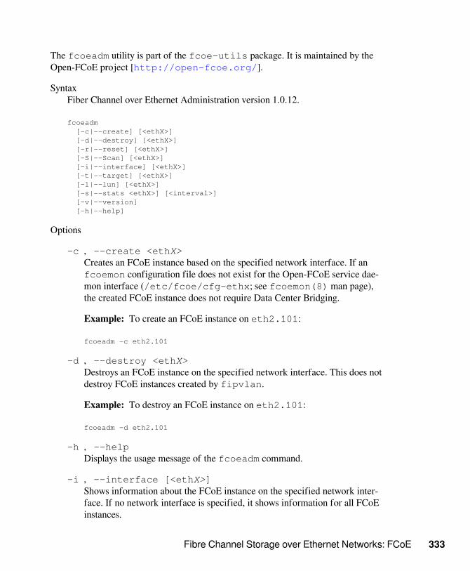
Fibre Channel Storage over Ethernet Networks: FCoE 333
The fcoeadm utility is part of the fcoe-utils package. It is maintained by theOpen-FCoE project [http://open-fcoe.org/].
SyntaxFiber Channel over Ethernet Administration version 1.0.12.
fcoeadm [-c|--create] [<ethX>] [-d|--destroy] [<ethX>] [-r|--reset] [<ethX>] [-S|--Scan] [<ethX>] [-i|--interface] [<ethX>] [-t|--target] [<ethX>] [-l|--lun] [<ethX>] [-s|--stats <ethX>] [<interval>] [-v|--version] [-h|--help]
Options
-c , --create <ethX>Creates an FCoE instance based on the specified network interface. If anfcoemon configuration file does not exist for the Open-FCoE service dae-mon interface (/etc/fcoe/cfg-ethx; see fcoemon(8) man page),the created FCoE instance does not require Data Center Bridging.
Example: To create an FCoE instance on eth2.101:
fcoeadm -c eth2.101
-d , --destroy <ethX>Destroys an FCoE instance on the specified network interface. This does notdestroy FCoE instances created by fipvlan.
Example: To destroy an FCoE instance on eth2.101:
fcoeadm -d eth2.101
-h , --helpDisplays the usage message of the fcoeadm command.
-i , --interface [<ethX>]Shows information about the FCoE instance on the specified network inter-face. If no network interface is specified, it shows information for all FCoEinstances.

334 Storage Administration Guide
Examples
To show information about all of the adapters and their ports that have FCoEinstances created:
fcoeadm -i
To show information about all of the FCoE instances on interface eth3:
fcoeadm -i eth3
-l , --lun [<ethX>]Shows detailed information about the discovered SCSI LUNs associated withthe FCoE instance on the specified network interface. If no network inter-face is specified, it shows information about SCSI LUNs from all FCoE in-stances.
Examples
To show detailed information about all of the LUNs discovered on all FCoEconnections:
fcoeadm -l
To show detailed information about all of the LUNs discovered on a specificconnections, such as eth3.101:
fcoeadm -l eth3.101
-r , --reset <ethX>Resets the FCoE instance on the specified network interface. This does notreset FCoE instances created by fipvlan.
Example: To reset the FCoE instance on eth2.101:
fcoeadm -r eth2.101
-s , --stats <ethX> [interval]Shows the statistics (including FC4 statistics) of the FCoE instance on thespecified network interface. It displays one line per given time interval. Spec-ify the interval value in whole integers greater than 0. The interval value isthe elapsed time of the interval in seconds. If an interval is not specified, thedefault interval is 1 second.
Examples:

Fibre Channel Storage over Ethernet Networks: FCoE 335
You can show statistics information about a specific eth3 port that hasFCoE instances. The statistics are displayed one line per time interval. Thedefault interval of one second is not specified in the command.
fcoeadm -s eth3
To show statistics information about a specific eth3 port that has FCoE in-stances, at an interval of 3 seconds. The statistics are displayed one line pertime interval.
fcoeadm -s eth3 3
-S , --Scan <ethX>Rescans for new targets and LUN for the specified network interface. Thisdoes not rescan any NPIV (N_Port ID Virtualization) instances created on thesame port, and does not rescan any FCoE instances created by fipvlan.
-t , --target [<ethX>]Shows information about the discovered targets associated with the FCoE in-stance on the specified network interface. If no network interface is speci-fied, it shows information about discovered targets from all FCoE instances.
Examples
You can show information about all of the discovered targets from all of theports that have FCoE instances. They might be on different adapter cards.After each discovered target, any associated LUNs are listed.
fcoeadm -t
You can show information about all of the discovered targets from a giveneth3 port having FCoE instance. After each discovered target, any associat-ed LUNs are listed.
fcoeadm -t eth3
-v , --versionDisplays the version of the fcoeadm command.
FCoE Response Examples
View FCoE Initiator Status for FC-ID Node/Port Number

336 Storage Administration Guide
fcoeadm -i eth0.201 Description: 82599EB 10-Gigabit SFI/SFP+ Network Connection Revision: 01 Manufacturer: Intel Corporation Serial Number: 001B219B258C Driver: ixgbe 3.3.8-k2 Number of Ports: 1
Symbolic Name: fcoe v0.1 over eth0.201 OS Device Name: host8 Node Name: 0x1000001B219B258E Port Name: 0x2000001B219B258E FabricName: 0x2001000573D38141 Speed: 10 Gbit Supported Speed: 10 Gbit MaxFrameSize: 2112 FC-ID (Port ID): 0x790003 State: Online
View FCoE Targets for FC-ID Node/Port Number
fcoeadm -t eth0.201 Interface: eth0.201 Roles: FCP Target Node Name: 0x200000D0231B5C72 Port Name: 0x210000D0231B5C72 Target ID: 0 MaxFrameSize: 2048 OS Device Name: rport-8:0-7 FC-ID (Port ID): 0x79000C State: Online
LUN ID Device Name Capacity Block Size Description ------ ----------- ---------- ---------- ---------------------------- 40 /dev/sdqi 792.84 GB 512 IFT DS S24F-R2840-4 (rev 386C) 72 /dev/sdpk 650.00 GB 512 IFT DS S24F-R2840-4 (rev 386C) 168 /dev/sdgy 1.30 TB 512 IFT DS S24F-R2840-4 (rev 386C)
16.6 Setting Up Partitions for anFCoE Initiator DiskYou can use the fdisk(8) command to set up partitions for an FCoE initiator disk.

Fibre Channel Storage over Ethernet Networks: FCoE 337
fdisk /dev/sdc Device contains neither a valid DOS partition table, nor Sun, SGI or OSF disklabel. Building a new DOS disklabel with disk identifier 0xfc691889. Changes will remain in memory only, until you decide to write them. After that, of course, the previous content won’t be recoverable.
Warning: Invalid flag 0x0000 of partition table 4 will be corrected by w(rite)
Command (n for help): n Command action e extended p primary partition (1-4)
p Partition number (1-4): 4 First cylinder (1-1017, default 1): Using default value 1 Last cylinder, *cylinders or *size(K,M,G) (1-1017, default 1017): Using default value 1017
Command (n for help): w The partition table has been altered!
Calling loctl() to re-read partition table. Syncing disks.
16.7 Creating a File System on anFCoE Initiator DiskYou can use the mkfs(8) command to create a file system on an FCoE initiatordisk.
mkfs /dev/sdc mke2fs 1.41.9 (22-Aug-2011) /dev/sdc is entire device, not just one partition! Proceed anyway? (y, n) y Filesystem label= OS type: Linux Block size=4096 (log-2) 262144 inodes, 1048576 blocks 52428 blocks (5.00%) reserved for the super user First data block=0 Maximum filesystem blocks=1073741824 32 block groups 32768 blocks per group, 32768 fragments per group 8192 inodes per group

338 Storage Administration Guide
Superblock backups stored on blocks: 32768, 98304, 163840, 229376, 294912, 819200, 804736
Writing inode tables: done Writing superblocks and filesystem accounting information: done
This filesystem will be automatically checked every 27 mounts or 180 days, whichever comes first. Use tune2fs -c or -i to override.
16.8 Additional InformationFor information, see the follow documentation:
• For information about the Open-FCoE service daemon, see the fcoemon(8)manpage.
• For information about the Open-FCoE Administration tool, see the fcoeadm(8)man page.
• For information about the Data Center Bridging Configuration tool, see thedcbtool(8) man page.
• For information about the Link Layer Discovery Protocol agent daemon, see thelldpad(8) man page.
• Open Fibre Channel over Ethernet Quick Start [http://www.open-fcoe.org/open-fcoe/wiki/quickstart].

LVM Volume Snapshots 339
LVM Volume Snapshots 17A Logical Volume Manager (LVM) logical volume snapshot is a copy-on-write tech-nology that monitors changes to an existing volume’s data blocks so that when a writeis made to one of the blocks, the block’s value at the snapshot time is copied to asnapshot volume. In this way, a point-in-time copy of the data is preserved until thesnapshot volume is deleted.
• Section 17.1, “Understanding Volume Snapshots” (page 339)
• Section 17.2, “Creating Linux Snapshots with LVM” (page 341)
• Section 17.3, “Monitoring a Snapshot” (page 342)
• Section 17.4, “Deleting Linux Snapshots” (page 342)
• Section 17.5, “Using Snapshots for Virtual Machines on a Virtual Host” (page 343)
• Section 17.6, “Merging a Snapshot with the Source Logical Volume to RevertChanges or Roll Back to a Previous State” (page 345)
17.1 Understanding VolumeSnapshotsA file system snapshot contains metadata about and data blocks from a source logicalvolume that have changed since the snapshot was taken. When you access data via the

340 Storage Administration Guide
snapshot, you see a point-in-time copy of the source logical volume. There is no needto restore data from backup media or to overwrite the changed data.
IMPORTANT
During the snapshot’s lifetime, the snapshot must be mounted before itssource logical volume can be mounted.
LVM volume snapshots allow you to create a backup from a point-in-time view ofthe file system. The snapshot is created instantly and persists until you delete it. Youcan backup the file system from the snapshot while the volume itself continues to beavailable for users. The snapshot initially contains some metadata about the snapshot,but no actual data from the source logical volume. Snapshot uses copy-on-write tech-nology to detect when data changes in an original data block. It copies the value itheld when the snapshot was taken to a block in the snapshot volume, then allows thenew data to be stored in the source block. As more blocks change from their originalvalue on the source logical volume, the snapshot size grows.
When you are sizing the snapshot, consider how much data is expected to change onthe source logical volume and how long you plan to keep the snapshot. The amount ofspace that you allocate for a snapshot volume can vary, depending on the size of thesource logical volume, how long you plan to keep the snapshot, and the number of da-ta blocks that are expected to change during the snapshot’s lifetime. The snapshot vol-ume cannot be resized after it is created. As a guide, create a snapshot volume that isabout 10% of the size of the original logical volume. If you anticipate that every blockin the source logical volume will change at least one time before you delete the snap-shot, then the snapshot volume should be at least as large as the source logical volumeplus some additional space for metadata about the snapshot volume. Less space is re-quired if the data changes infrequently or if the expected lifetime is sufficiently brief.
In LVM2, snapshots are read/write by default. When you write data directly to thesnapshot, that block is marked in the exception table as used, and never gets copiedfrom the source logical volume. You can mount the snapshot volume, and test appli-cation changes by writing data directly to the snapshot volume. You can easily discardthe changes by dismounting the snapshot, removing the snapshot, and then re-mount-ing the source logical volume.
In a virtual guest environment, you can use the snapshot function for LVM logicalvolumes you create on the server’s disks, just as you would on a physical server.

LVM Volume Snapshots 341
In a virtual host environment, you can use the snapshot function to back up the virtu-al machine’s storage back-end, or to test changes to a virtual machine image, such asfor patches or upgrades, without modifying the source logical volume. The virtual ma-chine must be using an LVM logical volume as its storage back-end, as opposed to us-ing a virtual disk file. You can mount the LVM logical volume and use it to store thevirtual machine image as a file-backed disk, or you can assign the LVM logical vol-ume as a physical disk to write to it as a block device.
Beginning in SLES 11 SP3, an LVM logical volume snapshots can be thinly provi-sioned. Thin provisioning is assumed if you to create a snapshot without a specifiedsize. The snapshot is created as a thin volume that uses space as needed from a thinpool. A thin snapshot volume has the same characteristics as any other thin volume.You can independently activate the volume, extend the volume, rename the volume,remove the volume, and even snapshot the volume.
IMPORTANT
To use thinly provisioned snapshots in a cluster, the source logical volumeand its snapshots must be managed in a single cluster resource. This allowsthe volume and its snapshots to always be mounted exclusively on the samenode.
When you are done with the snapshot, it is important to remove it from the system.A snapshot eventually fills up completely as data blocks change on the source logicalvolume. When the snapshot is full, it is disabled, which prevents you from remountingthe source logical volume.
If you create multiple snapshots for a source logical volume, remove the snapshots ina last created, first deleted order.
17.2 Creating Linux Snapshots withLVMThe Logical Volume Manager (LVM) can be used for creating snapshots of your filesystem.
• Open a terminal console, log in as the root user, then enter
lvcreate -s [-L <size>] -n snap_volume source_volume_path
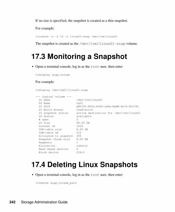
342 Storage Administration Guide
If no size is specified, the snapshot is created as a thin snapshot.
For example:
lvcreate -s -L 1G -n linux01-snap /dev/lvm/linux01
The snapshot is created as the /dev/lvm/linux01-snap volume.
17.3 Monitoring a Snapshot• Open a terminal console, log in as the root user, then enter
lvdisplay snap_volume
For example:
lvdisplay /dev/vg01/linux01-snap
--- Logical volume --- LV Name /dev/lvm/linux01 VG Name vg01 LV UUID QHVJYh-PR3s-A4SG-s4Aa-MyWN-Ra7a-HL47KL LV Write Access read/write LV snapshot status active destination for /dev/lvm/linux01 LV Status available # open 0 LV Size 80.00 GB Current LE 1024 COW-table size 8.00 GB COW-table LE 512 Allocated to snapshot 30% Snapshot chunk size 8.00 KB Segments 1 Allocation inherit Read ahead sectors 0 Block device 254:5
17.4 Deleting Linux Snapshots• Open a terminal console, log in as the root user, then enter
lvremove snap_volume_path

LVM Volume Snapshots 343
For example:
lvremove /dev/lvmvg/linux01-snap
17.5 Using Snapshots for VirtualMachines on a Virtual HostUsing an LVM logical volume for a virtual machine’s back-end storage allows flexi-bility in administering the underlying device, such as making it easier to move stor-age objects, create snapshots, and back up data. You can mount the LVM logical vol-ume and use it to store the virtual machine image as a file-backed disk, or you can as-sign the LVM logical volume as a physical disk to write to it as a block device. Youcan create a virtual disk image on the LVM logical volume, then snapshot the LVM.
You can leverage the read/write capability of the snapshot to create different in-stances of a virtual machine, where the changes are made to the snapshot for a partic-ular virtual machine instance. You can create a virtual disk image on an LVM logicalvolume, snapshot the source logical volume, and modify the snapshot for a particularvirtual machine instance. You can create another snapshot of the source logical vol-ume, and modify it for a different virtual machine instance. The majority of the datafor the different virtual machine instances resides with the image on the source logicalvolume.
You can also leverage the read/write capability of the snapshot to preserve the virtu-al disk image while testing patches or upgrades in the guest environment. You cre-ate a snapshot of the LVM volume that contains the image, and then run the virtualmachine on the snapshot location. The source logical volume is unchanged, and allchanges for that machine are written to the snapshot. To return to the source logicalvolume of the virtual machine image, you power off the virtual machine, then removethe snapshot from the source logical volume. To start over, you re-create the snapshot,mount the snapshot, and restart the virtual machine on the snapshot image.
IMPORTANT
The following procedure uses a file-backed virtual disk image and the Xenhypervisor. You can adapt the procedure in this section for other hypervisorsthat run on the SUSE Linux platform, such as KVM.

344 Storage Administration Guide
To run a file-backed virtual machine image from the snapshot volume:
1 Ensure that the source logical volume that contains the file-backed virtualmachine image is mounted, such as at mount point /var/lib/xen/images/<image_name>.
2 Create a snapshot of the LVM logical volume with enough space to store the dif-ferences that you expect.
lvcreate -s -L 20G -n myvm-snap /dev/lvmvg/myvm
If no size is specified, the snapshot is created as a thin snapshot.
3 Create a mount point where you will mount the snapshot volume.
mkdir -p /mnt/xen/vm/myvm-snap
4 Mount the snapshot volume at the mount point you created.
mount -t auto /dev/lvmvg/myvm-snap /mnt/xen/vm/myvm-snap
5 In a text editor, copy the configuration file for the source virtual machine, modifythe paths to point to the file-backed image file on the mounted snapshot volume,and save the file such as /etc/xen/myvm-snap.cfg.
6 Start the virtual machine using the mounted snapshot volume of the virtual ma-chine.
xm create -c /etc/xen/myvm-snap.cfg
7 (Optional) Remove the snapshot, and use the unchanged virtual machine image onthe source logical volume.
unmount /mnt/xenvms/myvm-snaplvremove -f /dev/lvmvg/mylvm-snap
8 (Optional) Repeat this process as desired.

LVM Volume Snapshots 345
17.6 Merging a Snapshot with theSource Logical Volume to RevertChanges or Roll Back to a PreviousStateSnapshots can be useful if you need to roll back or restore data on a volume to a pre-vious state. For example, you might need to revert data changes that resulted from anadministrator error or a failed or undesirable package installation or upgrade.
You can use the lvconvert --merge command to revert the changes made to anLVM logical volume. The merging begins as follows:
• If both the source logical volume and snapshot volume are not open, the merge be-gins immediately.
• If the source logical volume or snapshot volume are open, the merge starts the firsttime either the source logical volume or snapshot volume are activated and both areclosed.
• If the source logical volume cannot be closed, such as the root file system, themerge is deferred until the next time the server reboots and the source logical vol-ume is activated.
• If the source logical volume contains a virtual machine image, you must shut downthe virtual machine, deactivate the source logical volume and snapshot volume (bydismounting them in that order), and then issue the merge command. Because thesource logical volume is automatically remounted and the snapshot volume is delet-ed when the merge is complete, you should not restart the virtual machine until af-ter the merge is complete. After the merge is complete, you use the resulting logicalvolume for the virtual machine.
After a merge begins, the merge continues automatically after server restarts until itis complete. A new snapshot cannot be created for the source logical volume while amerge is in progress.
While the merge is in progress, reads or writes to the source logical volume are trans-parently redirected to the snapshot that is being merged. This allows users to immedi-

346 Storage Administration Guide
ately view and access the data as it was when the snapshot was created. They do notneed to wait for the merge to complete.
When the merge is complete, the source logical volume contains the same data as itdid when the snapshot was taken, plus any data changes made after the merge began.The resulting logical volume has the source logical volume’s name, minor number, andUUID. The source logical volume is automatically remounted, and the snapshot vol-ume is removed.
1 Open a terminal console, log in as the root user, then enter
lvconvert --merge [-b] [-i <seconds>] [<snap_volume_path>[...<snapN>]|@<volume_tag>]
You can specify one or multiple snapshots on the command line. You can alterna-tively tag multiple source logical volumes with the same volume tag then specify@<volume_tag> on the command line. The snapshots for the tagged volumesare merged to their respective source logical volumes. For information about tag-ging logical volumes, see Section 4.7, “Tagging LVM2 Storage Objects” (page 61).
The options include:
-b , --backgroundRun the daemon in the background. This allows multiple specified snapshots tobe merged concurrently in parallel.
-i , --interval <seconds>Report progress as a percentage at regular intervals. Specify the interval in sec-onds.
For more information about this command, see the lvconvert(8) man page.
For example:
lvconvert --merge /dev/lvmvg/linux01-snap
This command merges /dev/lvmvg/linux01-snap into its source logicalvolume.
lvconvert --merge @mytag

LVM Volume Snapshots 347
If lvol1, lvol2, and lvol3 are all tagged with mytag, each snapshot volumeis merged serially with its respective source logical volume; that is: lvol1, thenlvol2, then lvol3. If the --background option is specified, the snapshotsfor the respective tagged logical volume are merged concurrently in parallel.
2 (Optional) If both the source logical volume and snapshot volume are open andthey can be closed, you can manually deactivate and activate the source logical vol-ume to get the merge to start immediately.
umount <original_volume>lvchange -an <original_volume>lvchange -ay <original_volume>mount <original_volume> <mount_point>
For example:
umount /dev/lvmvg/lvol01lvchange -an /dev/lvmvg/lvol01lvchange -ay /dev/lvmvg/lvol01mount /dev/lvmvg/lvol01 /mnt/lvol01
3 (Optional) If both the source logical volume and snapshot volume are open andthe source logical volume cannot be closed, such as the root file system, you canrestart the server and mount the source logical volume to get the merge to start im-mediately after the restart.


Managing Access Control Lists over NFSv4 349
Managing Access ControlLists over NFSv4 18There is no single standard for Access Control Lists (ACLs) in Linux beyond the sim-ple user-group-others read, write, and execute (rwx) flags. One option for finer con-trol are the Draft POSIX ACLs, which were never formally standardised by POSIX.Another is the NFSv4 ACLs, which were designed to be part of the NFSv4 networkfile system with the goal of making something that provided reasonable compatibilitybetween POSIX systems on Linux and WIN32 systems on Microsoft Windows.
NFSv4 ACLs are not sufficient to correctly implement Draft POSIX ACLs so no at-tempt has been made to map ACL accesses on an NFSv4 client (such as using set-facl).
When using NFSv4, Draft POSIX ACLs cannot be used even in emulation andNFSv4 ACLs need to be used directly; i.e., while setfacl can work on NFSv3, itcannot work on NFSv4.+To allow NFSv4 ACLs to be used on an NFSv4 file system,SUSE Linux Enterprise Server provides the nfs4-acl-tools package which con-tains the following:
• nfs4-getfacl
• nfs4-setfacl
• nfs4-editacl
These operate in a generally similar way to getfacl and setfacl for examiningand modifying NFSv4 ACLs.These commands are effective only if the file system onthe NFS server provides full support for NFSv4 ACLs. Any limitation imposed by the
350 Storage Administration Guide
server will affect programs running on the client in that some particular combinationsof Access Control Entries (ACEs) might not be possible.
It is not supported to mount NFS volumes locally on the exporting NFS server.
Additional InformationFor information, see “Introduction to NFSv4 ACLs” on the Linux-nfs.orgWeb site [http://wiki.linux-nfs.org/wiki/index.php/ACLs#Introduction_to_NFSv4_ACLs].

Troubleshooting Storage Issues 351
Troubleshooting StorageIssues 19This section describes how to work around known issues for devices, softwareRAIDs, multipath I/O, and volumes.
• Section 19.1, “Is DM-MPIO Available for the Boot Partition?” (page 351)
• Section 19.2, “Btrfs Error: No space is left on device ” (page 352)
• Section 19.3, “Issues for Multipath I/O” (page 354)
• Section 19.4, “Issues for Software RAIDs” (page 354)
• Section 19.5, “Issues for iSCSI” (page 354)
• Section 19.6, “Issues for iSCSI LIO Target” (page 354)
19.1 Is DM-MPIO Available for theBoot Partition?Device Mapper Multipath I/O (DM-MPIO) is supported for the boot partition, begin-ning in SUSE Linux Enterprise Server 10 Support Pack 1. For information, see Sec-tion 7.12, “Configuring Multipath I/O for the Root Device” (page 162).

352 Storage Administration Guide
19.2 Btrfs Error: No space is left ondeviceThe root (/) partition using the Btrfs file system stops accepting data. You receive theerror “No space left on device”.
See the following sections for information about possible causes and prevention ofthis issue.
• Section 19.2.1, “Disk Space Consumed by Snapper Snapshots” (page 352)
• Section 19.2.2, “Disk Space Consumed by Log, Crash, and Cache Files ” (page 354)
19.2.1 Disk Space Consumed by SnapperSnapshotsIf Snapper is running for the Btrfs file system, the “No space left on de-vice” problem is typically caused by having too much data stored as snapshots onyour system.
You can remove some snapshots from Snapper, however, the snapshots are not delet-ed immediately and might not free up as much space as you need.
To delete files from Snapper:
1 Log in as the root user, then open a terminal console.
2 Gain back enough space for the system to come up.
2a At the command prompt, enter
btrfs filesystem show
Label: none uuid: 40123456-cb2c-4678-8b3d-d014d1c78c78 Total devices 1 FS bytes used 20.00GB devid 1 size 20.00GB used 20.00GB path /dev/sda3

Troubleshooting Storage Issues 353
2b Enter
btrfs fi balance start </mountpoint> -dusage=5
This command attempts to relocate data in empty or near-empty datachunks, allowing the space to be reclaimed and reassigned to metadata. Thiscan take awhile (many hours for 1 TB) although the system is otherwise us-able during this time.
3 List the snapshots in Snapper. Enter
snapper -c root list
4 Delete one or more snapshots from Snapper. Enter
snapper -c root delete #
Ensure that you delete the oldest snapshots first. The older a snapshot is, the moredisk space it occupies.
To help prevent this problem, you can change the Snapper cleanup defaults to bemore aggressive in the /etc/snapper/configs/root configuration file, orfor other mount points. Snapper provides three algorithms to clean up old snapshots.The algorithms are executed in a daily cron-job. The cleanup frequency is definedin the Snapper configuration for the mount point. Lower the TIMELINE_LIMIT pa-rameters for daily, monthly, and yearly to reduce how long and the number of snap-shots to be retained. For information, see “Adjusting the Config File” [https://www.suse.com/documentation/sles11/book_sle_admin/data/sec_snapper_config.html#sec_snapper_config_modify]in the SUSE Linux Enterprise Server Administration Guide [https://www.suse.com/documentation/sles11/book_sle_admin/data/book_sle_admin.html].
If you use Snapper with Btrfs on the file system disk, it is advisable to reserve twicethe amount of disk space than the standard storage proposal. The YaST Partitioner au-tomatically proposes twice the standard disk space in the Btrfs storage proposal forthe root file system.

354 Storage Administration Guide
19.2.2 Disk Space Consumed by Log,Crash, and Cache FilesIf the system disk is filling up with data, you can try deleting files from /var/log,/var/crash, and /var/cache.
The Btrfs root file system subvolumes /var/log, /var/crash and /var/cache can use all of the available disk space during normal operation, and cause asystem malfunction. To help avoid this situation, SUSE Linux Enterprise Server of-fers Btrfs quota support for subvolumes. See the btrfs(8) manual page for moredetails.
19.3 Issues for Multipath I/OSee Section 7.19, “Troubleshooting MPIO” (page 179).
19.4 Issues for Software RAIDsSee Section 8.3, “Troubleshooting Software RAIDs” (page 188).
19.5 Issues for iSCSISee Section 14.5, “Troubleshooting iSCSI” (page 282).
19.6 Issues for iSCSI LIO TargetSee Section 15.8, “Troubleshooting iSCSI LIO Target Server” (page 317).

GNU Licenses AThis appendix contains the GNU General Public License Version 2 and the GNU FreeDocumentation License Version 1.2.
• Section A.1, “GNU General Public License” (page 355)
• Section A.2, “GNU Free Documentation License” (page 358)
GNU General Public LicenseVersion 2, June 1991
Copyright (C) 1989, 1991 Free Software Foundation, Inc. 59 Temple Place - Suite 330, Boston, MA 02111-1307, USA
Everyone is permitted to copy and distribute verbatim copies of this license document, but changing it is not allowed.
PreambleThe licenses for most software are designed to take away your freedom to share and change it. By contrast, the GNU General Public License is in-tended to guarantee your freedom to share and change free software--to ensure that the software is free for all its users. This General Public Licenseapplies to most of the Free Software Foundation’s software and to any other program whose authors commit to using it. (Some other Free SoftwareFoundation software is covered by the GNU Library General Public License instead.) You can apply it to your programs, too.
When we speak of free software, we are referring to freedom, not price. Our General Public Licenses are designed to ensure that you have the free-dom to distribute copies of free software (and charge for this service if you wish), that you receive source code or can get it if you want it, that you canchange the software or use pieces of it in new free programs; and that you know you can do these things.
To protect your rights, we need to make restrictions that forbid anyone to deny you these rights or to ask you to surrender the rights. These restrictionstranslate to certain responsibilities for you if you distribute copies of the software, or if you modify it.
For example, if you distribute copies of such a program, whether gratis or for a fee, you must give the recipients all the rights that you have. You mustensure that they, too, receive or can get the source code. And you must show them these terms so they know their rights.
We protect your rights with two steps: (1) copyright the software, and (2) offer you this license which gives you legal permission to copy, distributeand/or modify the software.
Also, for each author’s protection and ours, we want to make certain that everyone understands that there is no warranty for this free software. If thesoftware is modified by someone else and passed on, we want its recipients to know that what they have is not the original, so that any problems intro-duced by others will not reflect on the original authors’ reputations.
Finally, any free program is threatened constantly by software patents. We wish to avoid the danger that redistributors of a free program will indi-vidually obtain patent licenses, in effect making the program proprietary. To prevent this, we have made it clear that any patent must be licensed foreveryone’s free use or not licensed at all.

356 Storage Administration Guide
The precise terms and conditions for copying, distribution and modification follow.
GNU GENERAL PUBLIC LICENSE TERMS AND CONDITIONS FOR COPYING, DISTRIBUTION AND MODIFI-CATION0. This License applies to any program or other work which contains a notice placed by the copyright holder saying it may be distributed under theterms of this General Public License. The “Program”, below, refers to any such program or work, and a “work based on the Program” means either theProgram or any derivative work under copyright law: that is to say, a work containing the Program or a portion of it, either verbatim or with modifica-tions and/or translated into another language. (Hereinafter, translation is included without limitation in the term “modification”.) Each licensee is ad-dressed as “you”.
Activities other than copying, distribution and modification are not covered by this License; they are outside its scope. The act of running the Programis not restricted, and the output from the Program is covered only if its contents constitute a work based on the Program (independent of having beenmade by running the Program). Whether that is true depends on what the Program does.
1. You may copy and distribute verbatim copies of the Program’s source code as you receive it, in any medium, provided that you conspicuously andappropriately publish on each copy an appropriate copyright notice and disclaimer of warranty; keep intact all the notices that refer to this License andto the absence of any warranty; and give any other recipients of the Program a copy of this License along with the Program.
You may charge a fee for the physical act of transferring a copy, and you may at your option offer warranty protection in exchange for a fee.
2. You may modify your copy or copies of the Program or any portion of it, thus forming a work based on the Program, and copy and distribute suchmodifications or work under the terms of Section 1 above, provided that you also meet all of these conditions:
a) You must cause the modified files to carry prominent notices stating that you changed the files and the date of any change.
b) You must cause any work that you distribute or publish, that in whole or in part contains or is derived from the Program or any part thereof, to belicensed as a whole at no charge to all third parties under the terms of this License.
c) If the modified program normally reads commands interactively when run, you must cause it, when started running for such interactive use in themost ordinary way, to print or display an announcement including an appropriate copyright notice and a notice that there is no warranty (or else, say-ing that you provide a warranty) and that users may redistribute the program under these conditions, and telling the user how to view a copy of this Li-cense. (Exception: if the Program itself is interactive but does not normally print such an announcement, your work based on the Program is not re-quired to print an announcement.)
These requirements apply to the modified work as a whole. If identifiable sections of that work are not derived from the Program, and can be rea-sonably considered independent and separate works in themselves, then this License, and its terms, do not apply to those sections when you distributethem as separate works. But when you distribute the same sections as part of a whole which is a work based on the Program, the distribution of thewhole must be on the terms of this License, whose permissions for other licensees extend to the entire whole, and thus to each and every part regard-less of who wrote it.
Thus, it is not the intent of this section to claim rights or contest your rights to work written entirely by you; rather, the intent is to exercise the right tocontrol the distribution of derivative or collective works based on the Program.
In addition, mere aggregation of another work not based on the Program with the Program (or with a work based on the Program) on a volume of astorage or distribution medium does not bring the other work under the scope of this License.
3. You may copy and distribute the Program (or a work based on it, under Section 2) in object code or executable form under the terms of Sections 1and 2 above provided that you also do one of the following:
a) Accompany it with the complete corresponding machine-readable source code, which must be distributed under the terms of Sections 1 and 2above on a medium customarily used for software interchange; or,
b) Accompany it with a written offer, valid for at least three years, to give any third party, for a charge no more than your cost of physically perform-ing source distribution, a complete machine-readable copy of the corresponding source code, to be distributed under the terms of Sections 1 and 2above on a medium customarily used for software interchange; or,
c) Accompany it with the information you received as to the offer to distribute corresponding source code. (This alternative is allowed only for non-commercial distribution and only if you received the program in object code or executable form with such an offer, in accord with Subsection babove.)
The source code for a work means the preferred form of the work for making modifications to it. For an executable work, complete source codemeans all the source code for all modules it contains, plus any associated interface definition files, plus the scripts used to control compilation and in-stallation of the executable. However, as a special exception, the source code distributed need not include anything that is normally distributed (in ei-ther source or binary form) with the major components (compiler, kernel, and so on) of the operating system on which the executable runs, unless thatcomponent itself accompanies the executable.
If distribution of executable or object code is made by offering access to copy from a designated place, then offering equivalent access to copy thesource code from the same place counts as distribution of the source code, even though third parties are not compelled to copy the source along withthe object code.
4. You may not copy, modify, sublicense, or distribute the Program except as expressly provided under this License. Any attempt otherwise to copy,modify, sublicense or distribute the Program is void, and will automatically terminate your rights under this License. However, parties who have re-ceived copies, or rights, from you under this License will not have their licenses terminated so long as such parties remain in full compliance.

GNU Licenses 357
5. You are not required to accept this License, since you have not signed it. However, nothing else grants you permission to modify or distribute theProgram or its derivative works. These actions are prohibited by law if you do not accept this License. Therefore, by modifying or distributing the Pro-gram (or any work based on the Program), you indicate your acceptance of this License to do so, and all its terms and conditions for copying, distribut-ing or modifying the Program or works based on it.
6. Each time you redistribute the Program (or any work based on the Program), the recipient automatically receives a license from the original licen-sor to copy, distribute or modify the Program subject to these terms and conditions. You may not impose any further restrictions on the recipients’ ex-ercise of the rights granted herein. You are not responsible for enforcing compliance by third parties to this License.
7. If, as a consequence of a court judgment or allegation of patent infringement or for any other reason (not limited to patent issues), conditions areimposed on you (whether by court order, agreement or otherwise) that contradict the conditions of this License, they do not excuse you from the con-ditions of this License. If you cannot distribute so as to satisfy simultaneously your obligations under this License and any other pertinent obligations,then as a consequence you may not distribute the Program at all. For example, if a patent license would not permit royalty-free redistribution of theProgram by all those who receive copies directly or indirectly through you, then the only way you could satisfy both it and this License would be to re-frain entirely from distribution of the Program.
If any portion of this section is held invalid or unenforceable under any particular circumstance, the balance of the section is intended to apply and thesection as a whole is intended to apply in other circumstances.
It is not the purpose of this section to induce you to infringe any patents or other property right claims or to contest validity of any such claims; thissection has the sole purpose of protecting the integrity of the free software distribution system, which is implemented by public license practices.Many people have made generous contributions to the wide range of software distributed through that system in reliance on consistent application ofthat system; it is up to the author/donor to decide if he or she is willing to distribute software through any other system and a licensee cannot imposethat choice.
This section is intended to make thoroughly clear what is believed to be a consequence of the rest of this License.
8. If the distribution and/or use of the Program is restricted in certain countries either by patents or by copyrighted interfaces, the original copyrightholder who places the Program under this License may add an explicit geographical distribution limitation excluding those countries, so that distribu-tion is permitted only in or among countries not thus excluded. In such case, this License incorporates the limitation as if written in the body of this Li-cense.
9. The Free Software Foundation may publish revised and/or new versions of the General Public License from time to time. Such new versions will besimilar in spirit to the present version, but may differ in detail to address new problems or concerns.
Each version is given a distinguishing version number. If the Program specifies a version number of this License which applies to it and “any later ver-sion”, you have the option of following the terms and conditions either of that version or of any later version published by the Free Software Founda-tion. If the Program does not specify a version number of this License, you may choose any version ever published by the Free Software Foundation.
10. If you wish to incorporate parts of the Program into other free programs whose distribution conditions are different, write to the author to ask forpermission. For software which is copyrighted by the Free Software Foundation, write to the Free Software Foundation; we sometimes make excep-tions for this. Our decision will be guided by the two goals of preserving the free status of all derivatives of our free software and of promoting thesharing and reuse of software generally.
NO WARRANTY
11. BECAUSE THE PROGRAM IS LICENSED FREE OF CHARGE, THERE IS NO WARRANTY FOR THE PROGRAM, TO THE EXTENTPERMITTED BY APPLICABLE LAW. EXCEPT WHEN OTHERWISE STATED IN WRITING THE COPYRIGHT HOLDERS AND/OROTHER PARTIES PROVIDE THE PROGRAM “AS IS” WITHOUT WARRANTY OF ANY KIND, EITHER EXPRESSED OR IMPLIED, IN-CLUDING, BUT NOT LIMITED TO, THE IMPLIED WARRANTIES OF MERCHANTABILITY AND FITNESS FOR A PARTICULAR PUR-POSE. THE ENTIRE RISK AS TO THE QUALITY AND PERFORMANCE OF THE PROGRAM IS WITH YOU. SHOULD THE PROGRAMPROVE DEFECTIVE, YOU ASSUME THE COST OF ALL NECESSARY SERVICING, REPAIR OR CORRECTION.
12. IN NO EVENT UNLESS REQUIRED BY APPLICABLE LAW OR AGREED TO IN WRITING WILL ANY COPYRIGHT HOLDER, ORANY OTHER PARTY WHO MAY MODIFY AND/OR REDISTRIBUTE THE PROGRAM AS PERMITTED ABOVE, BE LIABLE TO YOUFOR DAMAGES, INCLUDING ANY GENERAL, SPECIAL, INCIDENTAL OR CONSEQUENTIAL DAMAGES ARISING OUT OF THE USEOR INABILITY TO USE THE PROGRAM (INCLUDING BUT NOT LIMITED TO LOSS OF DATA OR DATA BEING RENDERED INACCU-RATE OR LOSSES SUSTAINED BY YOU OR THIRD PARTIES OR A FAILURE OF THE PROGRAM TO OPERATE WITH ANY OTHERPROGRAMS), EVEN IF SUCH HOLDER OR OTHER PARTY HAS BEEN ADVISED OF THE POSSIBILITY OF SUCH DAMAGES.
END OF TERMS AND CONDITIONS
How to Apply These Terms to Your New ProgramsIf you develop a new program, and you want it to be of the greatest possible use to the public, the best way to achieve this is to make it free softwarewhich everyone can redistribute and change under these terms.
To do so, attach the following notices to the program. It is safest to attach them to the start of each source file to most effectively convey the exclusionof warranty; and each file should have at least the “copyright” line and a pointer to where the full notice is found.
one line to give the program’s name and an idea of what it does.

358 Storage Administration Guide
Copyright (C) yyyy name of author
This program is free software; you can redistribute it and/ormodify it under the terms of the GNU General Public Licenseas published by the Free Software Foundation; either version 2of the License, or (at your option) any later version.
This program is distributed in the hope that it will be useful,but WITHOUT ANY WARRANTY; without even the implied warranty ofMERCHANTABILITY or FITNESS FOR A PARTICULAR PURPOSE. See theGNU General Public License for more details.
You should have received a copy of the GNU General Public Licensealong with this program; if not, write to the Free SoftwareFoundation, Inc., 59 Temple Place - Suite 330, Boston, MA 02111-1307,USA.
Also add information on how to contact you by electronic and paper mail.
If the program is interactive, make it output a short notice like this when it starts in an interactive mode:
Gnomovision version 69, Copyright (C) year name of authorGnomovision comes with ABSOLUTELY NO WARRANTY; for detailstype `show w’. This is free software, and you are welcometo redistribute it under certain conditions; type `show c’ for details.
The hypothetical commands `show w’ and `show c’ should show the appropriate parts of the General Public License. Of course, the commands you usemay be called something other than `show w’ and `show c’; they could even be mouse-clicks or menu items--whatever suits your program.
You should also get your employer (if you work as a programmer) or your school, if any, to sign a “copyright disclaimer” for the program, if neces-sary. Here is a sample; alter the names:
Yoyodyne, Inc., hereby disclaims all copyrightinterest in the program `Gnomovision’(which makes passes at compilers) written by James Hacker.
signature of Ty Coon, 1 April 1989Ty Coon, President of Vice
This General Public License does not permit incorporating your program into proprietary programs. If your program is a subroutine library, you mayconsider it more useful to permit linking proprietary applications with the library. If this is what you want to do, use the GNU Lesser General PublicLicense instead of this License.
GNU Free Documentation LicenseVersion 1.2, November 2002
Copyright (C) 2000,2001,2002 Free Software Foundation, Inc. 59 Temple Place, Suite 330, Boston, MA 02111-1307 USA
Everyone is permitted to copy and distribute verbatim copies of this license document, but changing it is not allowed.
PREAMBLEThe purpose of this License is to make a manual, textbook, or other functional and useful document “free” in the sense of freedom: to assure everyonethe effective freedom to copy and redistribute it, with or without modifying it, either commercially or noncommercially. Secondarily, this License pre-serves for the author and publisher a way to get credit for their work, while not being considered responsible for modifications made by others.

GNU Licenses 359
This License is a kind of “copyleft”, which means that derivative works of the document must themselves be free in the same sense. It complementsthe GNU General Public License, which is a copyleft license designed for free software.
We have designed this License in order to use it for manuals for free software, because free software needs free documentation: a free program shouldcome with manuals providing the same freedoms that the software does. But this License is not limited to software manuals; it can be used for any tex-tual work, regardless of subject matter or whether it is published as a printed book. We recommend this License principally for works whose purposeis instruction or reference.
APPLICABILITY AND DEFINITIONSThis License applies to any manual or other work, in any medium, that contains a notice placed by the copyright holder saying it can be distributed un-der the terms of this License. Such a notice grants a world-wide, royalty-free license, unlimited in duration, to use that work under the conditions stat-ed herein. The “Document”, below, refers to any such manual or work. Any member of the public is a licensee, and is addressed as “you”. You acceptthe license if you copy, modify or distribute the work in a way requiring permission under copyright law.
A “Modified Version” of the Document means any work containing the Document or a portion of it, either copied verbatim, or with modificationsand/or translated into another language.
A “Secondary Section” is a named appendix or a front-matter section of the Document that deals exclusively with the relationship of the publishers orauthors of the Document to the Document’s overall subject (or to related matters) and contains nothing that could fall directly within that overall sub-ject. (Thus, if the Document is in part a textbook of mathematics, a Secondary Section may not explain any mathematics.) The relationship could bea matter of historical connection with the subject or with related matters, or of legal, commercial, philosophical, ethical or political position regardingthem.
The “Invariant Sections” are certain Secondary Sections whose titles are designated, as being those of Invariant Sections, in the notice that says that theDocument is released under this License. If a section does not fit the above definition of Secondary then it is not allowed to be designated as Invariant.The Document may contain zero Invariant Sections. If the Document does not identify any Invariant Sections then there are none.
The “Cover Texts” are certain short passages of text that are listed, as Front-Cover Texts or Back-Cover Texts, in the notice that says that the Docu-ment is released under this License. A Front-Cover Text may be at most 5 words, and a Back-Cover Text may be at most 25 words.
A “Transparent” copy of the Document means a machine-readable copy, represented in a format whose specification is available to the general pub-lic, that is suitable for revising the document straightforwardly with generic text editors or (for images composed of pixels) generic paint programs or(for drawings) some widely available drawing editor, and that is suitable for input to text formatters or for automatic translation to a variety of formatssuitable for input to text formatters. A copy made in an otherwise Transparent file format whose markup, or absence of markup, has been arranged tothwart or discourage subsequent modification by readers is not Transparent. An image format is not Transparent if used for any substantial amount oftext. A copy that is not“Transparent” is called “Opaque”.
Examples of suitable formats for Transparent copies include plain ASCII without markup, Texinfo input format, LaTeX input format, SGML or XMLusing a publicly available DTD, and standard-conforming simple HTML, PostScript or PDF designed for human modification. Examples of trans-parent image formats include PNG, XCF and JPG. Opaque formats include proprietary formats that can be read and edited only by proprietary wordprocessors, SGML or XML for which the DTD and/or processing tools are not generally available, and the machine-generated HTML, PostScript orPDF produced by some word processors for output purposes only.
The “Title Page” means, for a printed book, the title page itself, plus such following pages as are needed to hold, legibly, the material this License re-quires to appear in the title page. For works in formats which do not have any title page as such, “Title Page” means the text near the most prominentappearance of the work’s title, preceding the beginning of the body of the text.
A section “Entitled XYZ” means a named subunit of the Document whose title either is precisely XYZ or contains XYZ in parentheses following textthat translates XYZ in another language. (Here XYZ stands for a specific section name mentioned below, such as “Acknowledgements”, “Dedications”,“Endorsements”, or “History”.) To “Preserve the Title” of such a section when you modify the Document means that it remains a section “EntitledXYZ” according to this definition.
The Document may include Warranty Disclaimers next to the notice which states that this License applies to the Document. These Warranty Dis-claimers are considered to be included by reference in this License, but only as regards disclaiming warranties: any other implication that these War-ranty Disclaimers may have is void and has no effect on the meaning of this License.
VERBATIM COPYINGYou may copy and distribute the Document in any medium, either commercially or noncommercially, provided that this License, the copyright no-tices, and the license notice saying this License applies to the Document are reproduced in all copies, and that you add no other conditions whatsoeverto those of this License. You may not use technical measures to obstruct or control the reading or further copying of the copies you make or distribute.However, you may accept compensation in exchange for copies. If you distribute a large enough number of copies you must also follow the conditionsin section 3.
You may also lend copies, under the same conditions stated above, and you may publicly display copies.
COPYING IN QUANTITYIf you publish printed copies (or copies in media that commonly have printed covers) of the Document, numbering more than 100, and the Document’slicense notice requires Cover Texts, you must enclose the copies in covers that carry, clearly and legibly, all these Cover Texts: Front-Cover Texts onthe front cover, and Back-Cover Texts on the back cover. Both covers must also clearly and legibly identify you as the publisher of these copies. Thefront cover must present the full title with all words of the title equally prominent and visible. You may add other material on the covers in addition.

360 Storage Administration Guide
Copying with changes limited to the covers, as long as they preserve the title of the Document and satisfy these conditions, can be treated as verbatimcopying in other respects.
If the required texts for either cover are too voluminous to fit legibly, you should put the first ones listed (as many as fit reasonably) on the actual cov-er, and continue the rest onto adjacent pages.
If you publish or distribute Opaque copies of the Document numbering more than 100, you must either include a machine-readable Transparent copyalong with each Opaque copy, or state in or with each Opaque copy a computer-network location from which the general network-using public has ac-cess to download using public-standard network protocols a complete Transparent copy of the Document, free of added material. If you use the latteroption, you must take reasonably prudent steps, when you begin distribution of Opaque copies in quantity, to ensure that this Transparent copy will re-main thus accessible at the stated location until at least one year after the last time you distribute an Opaque copy (directly or through your agents orretailers) of that edition to the public.
It is requested, but not required, that you contact the authors of the Document well before redistributing any large number of copies, to give them achance to provide you with an updated version of the Document.
MODIFICATIONSYou may copy and distribute a Modified Version of the Document under the conditions of sections 2 and 3 above, provided that you release the Modi-fied Version under precisely this License, with the Modified Version filling the role of the Document, thus licensing distribution and modification ofthe Modified Version to whoever possesses a copy of it. In addition, you must do these things in the Modified Version:
A. Use in the Title Page (and on the covers, if any) a title distinct from that of the Document, and from those of previous versions (which should, ifthere were any, be listed in the History section of the Document). You may use the same title as a previous version if the original publisher of that ver-sion gives permission.
B. List on the Title Page, as authors, one or more persons or entities responsible for authorship of the modifications in the Modified Version, togeth-er with at least five of the principal authors of the Document (all of its principal authors, if it has fewer than five), unless they release you from this re-quirement.
C. State on the Title page the name of the publisher of the Modified Version, as the publisher.
D. Preserve all the copyright notices of the Document.
E. Add an appropriate copyright notice for your modifications adjacent to the other copyright notices.
F. Include, immediately after the copyright notices, a license notice giving the public permission to use the Modified Version under the terms of thisLicense, in the form shown in the Addendum below.
G. Preserve in that license notice the full lists of Invariant Sections and required Cover Texts given in the Document’s license notice.
H. Include an unaltered copy of this License.
I. Preserve the section Entitled “History”, Preserve its Title, and add to it an item stating at least the title, year, new authors, and publisher of the Mod-ified Version as given on the Title Page. If there is no section Entitled “History” in the Document, create one stating the title, year, authors, and pub-lisher of the Document as given on its Title Page, then add an item describing the Modified Version as stated in the previous sentence.
J. Preserve the network location, if any, given in the Document for public access to a Transparent copy of the Document, and likewise the networklocations given in the Document for previous versions it was based on. These may be placed in the “History” section. You may omit a network locationfor a work that was published at least four years before the Document itself, or if the original publisher of the version it refers to gives permission.
K. For any section Entitled “Acknowledgements” or “Dedications”, Preserve the Title of the section, and preserve in the section all the substance andtone of each of the contributor acknowledgements and/or dedications given therein.
L. Preserve all the Invariant Sections of the Document, unaltered in their text and in their titles. Section numbers or the equivalent are not consideredpart of the section titles.
M. Delete any section Entitled “Endorsements”. Such a section may not be included in the Modified Version.
N. Do not retitle any existing section to be Entitled “Endorsements” or to conflict in title with any Invariant Section.
O. Preserve any Warranty Disclaimers.
If the Modified Version includes new front-matter sections or appendices that qualify as Secondary Sections and contain no material copied from theDocument, you may at your option designate some or all of these sections as invariant. To do this, add their titles to the list of Invariant Sections in theModified Version’s license notice. These titles must be distinct from any other section titles.
You may add a section Entitled “Endorsements”, provided it contains nothing but endorsements of your Modified Version by various parties--for ex-ample, statements of peer review or that the text has been approved by an organization as the authoritative definition of a standard.
You may add a passage of up to five words as a Front-Cover Text, and a passage of up to 25 words as a Back-Cover Text, to the end of the list of Cov-er Texts in the Modified Version. Only one passage of Front-Cover Text and one of Back-Cover Text may be added by (or through arrangementsmade by) any one entity. If the Document already includes a cover text for the same cover, previously added by you or by arrangement made by the

GNU Licenses 361
same entity you are acting on behalf of, you may not add another; but you may replace the old one, on explicit permission from the previous publisherthat added the old one.
The author(s) and publisher(s) of the Document do not by this License give permission to use their names for publicity for or to assert or imply en-dorsement of any Modified Version.
COMBINING DOCUMENTSYou may combine the Document with other documents released under this License, under the terms defined in section 4 above for modified versions,provided that you include in the combination all of the Invariant Sections of all of the original documents, unmodified, and list them all as InvariantSections of your combined work in its license notice, and that you preserve all their Warranty Disclaimers.
The combined work need only contain one copy of this License, and multiple identical Invariant Sections may be replaced with a single copy. If thereare multiple Invariant Sections with the same name but different contents, make the title of each such section unique by adding at the end of it, inparentheses, the name of the original author or publisher of that section if known, or else a unique number. Make the same adjustment to the sectiontitles in the list of Invariant Sections in the license notice of the combined work.
In the combination, you must combine any sections Entitled “History” in the various original documents, forming one section Entitled “History”; like-wise combine any sections Entitled “Acknowledgements”, and any sections Entitled “Dedications”. You must delete all sections Entitled “Endorse-ments”.
COLLECTIONS OF DOCUMENTSYou may make a collection consisting of the Document and other documents released under this License, and replace the individual copies of this Li-cense in the various documents with a single copy that is included in the collection, provided that you follow the rules of this License for verbatimcopying of each of the documents in all other respects.
You may extract a single document from such a collection, and distribute it individually under this License, provided you insert a copy of this Licenseinto the extracted document, and follow this License in all other respects regarding verbatim copying of that document.
AGGREGATION WITH INDEPENDENT WORKSA compilation of the Document or its derivatives with other separate and independent documents or works, in or on a volume of a storage or distribu-tion medium, is called an “aggregate” if the copyright resulting from the compilation is not used to limit the legal rights of the compilation’s users be-yond what the individual works permit. When the Document is included in an aggregate, this License does not apply to the other works in the aggre-gate which are not themselves derivative works of the Document.
If the Cover Text requirement of section 3 is applicable to these copies of the Document, then if the Document is less than one half of the entire ag-gregate, the Document’s Cover Texts may be placed on covers that bracket the Document within the aggregate, or the electronic equivalent of covers ifthe Document is in electronic form. Otherwise they must appear on printed covers that bracket the whole aggregate.
TRANSLATIONTranslation is considered a kind of modification, so you may distribute translations of the Document under the terms of section 4. Replacing InvariantSections with translations requires special permission from their copyright holders, but you may include translations of some or all Invariant Sectionsin addition to the original versions of these Invariant Sections. You may include a translation of this License, and all the license notices in the Docu-ment, and any Warranty Disclaimers, provided that you also include the original English version of this License and the original versions of those no-tices and disclaimers. In case of a disagreement between the translation and the original version of this License or a notice or disclaimer, the originalversion will prevail.
If a section in the Document is Entitled“Acknowledgements”, “Dedications”, or “History”, the requirement (section 4) to Preserve its Title (section 1)will typically require changing the actual title.
TERMINATIONYou may not copy, modify, sublicense, or distribute the Document except as expressly provided for under this License. Any other attempt to copy,modify, sublicense or distribute the Document is void, and will automatically terminate your rights under this License. However, parties who have re-ceived copies, or rights, from you under this License will not have their licenses terminated so long as such parties remain in full compliance.
FUTURE REVISIONS OF THIS LICENSEThe Free Software Foundation may publish new, revised versions of the GNU Free Documentation License from time to time. Such new versions willbe similar in spirit to the present version, but may differ in detail to address new problems or concerns. See http://www.gnu.org/copyleft/.
Each version of the License is given a distinguishing version number. If the Document specifies that a particular numbered version of this License “orany later version” applies to it, you have the option of following the terms and conditions either of that specified version or of any later version that hasbeen published (not as a draft) by the Free Software Foundation. If the Document does not specify a version number of this License, you may chooseany version ever published (not as a draft) by the Free Software Foundation.
ADDENDUM: How to use this License for your documentsTo use this License in a document you have written, include a copy of the License in the document and put the following copyright and license noticesjust after the title page:
362 Storage Administration Guide
Copyright (c) YEAR YOUR NAME.Permission is granted to copy, distribute and/or modify this documentunder the terms of the GNU Free Documentation License, Version 1.2or any later version published by the Free Software Foundation;with no Invariant Sections, no Front-Cover Texts, and no Back-CoverTexts.A copy of the license is included in the section entitled “GNUFree Documentation License”.
If you have Invariant Sections, Front-Cover Texts and Back-Cover Texts, replace the “with...Texts.” line with this:
with the Invariant Sections being LIST THEIR TITLES, with theFront-Cover Texts being LIST, and with the Back-Cover Texts being LIST.
If you have Invariant Sections without Cover Texts, or some other combination of the three, merge those two alternatives to suit the situation.
If your document contains nontrivial examples of program code, we recommend releasing these examples in parallel under your choice of free soft-ware license, such as the GNU General Public License, to permit their use in free software.

Documentation Updates BThis section contains information about documentation content changes made to theSUSE Linux Enterprise Server Storage Administration Guide since the initial release ofSUSE Linux Enterprise Server 11.
This document was updated on the following dates:
• Section B.1, “May 12, 2015” (page 364)
• Section B.2, “December 16, 2013” (page 365)
• Section B.3, “November 4, 2013” (page 365)
• Section B.4, “October 14, 2013” (page 365)
• Section B.5, “October 4, 2013” (page 366)
• Section B.6, “June 2013 (SLES 11 SP3)” (page 368)
• Section B.7, “March 19, 2013” (page 372)
• Section B.8, “March 11, 2013” (page 373)
• Section B.9, “February 8, 2013” (page 374)
• Section B.10, “January 8, 2013” (page 374)
• Section B.11, “November 14, 2012” (page 376)
• Section B.12, “October 29, 2012” (page 377)

364 Storage Administration Guide
• Section B.13, “October 19, 2012” (page 377)
• Section B.14, “September 28, 2012” (page 378)
• Section B.15, “April 12, 2012” (page 380)
• Section B.16, “February 27, 2012 (SLES 11 SP2)” (page 381)
• Section B.17, “July 12, 2011” (page 385)
• Section B.18, “June 14, 2011” (page 386)
• Section B.19, “May 5, 2011” (page 387)
• Section B.20, “January 2011” (page 387)
• Section B.21, “September 16, 2010” (page 388)
• Section B.22, “June 21, 2010” (page 389)
• Section B.23, “May 2010 (SLES 11 SP1)” (page 390)
• Section B.24, “February 23, 2010” (page 393)
• Section B.25, “December 1, 2009” (page 394)
• Section B.26, “October 20, 2009” (page 396)
• Section B.27, “August 3, 2009” (page 397)
• Section B.28, “June 22, 2009” (page 397)
• Section B.29, “May 21, 2009” (page 399)
B.1 May 12, 2015Updates were made to fix the following bugs and feature requests:
• Make clear that BTRFS compression is not supported (Bugzilla #864606 and#879021).
• State that IPv6 is supported with iSCSI (feature request #314804).

Documentation Updates 365
• The ncpfs file system is no longer supported (feature request #313107).
B.2 December 16, 2013
B.2.1 Managing Multipath I/O for DevicesUpdates were made to the following section. The changes are explained below.
Location Change
Section 7.8, “Blacklisting Non-Mul-tipath Devices” (page 138)
Corrected examples for cciss:
devnode "^cciss.c[0-9]d[0-9].*"
devnode "^cciss.c[0-9]d[0-9]*[p[0-9]*]"
B.3 November 4, 2013
B.3.1 Managing Multipath I/O for DevicesUpdates were made to the following section. The changes are explained below.
Location Change
Section 7.4.2, “Partitioning Multi-path Devices” (page 127)
Added issues related to partitioningmultipath devices.
B.4 October 14, 2013Updates were made to the following section. The changes are explained below.

366 Storage Administration Guide
B.4.1 iSNS for LinuxLocation Change
Section 13.3.3, “AddingiSCSI Nodes to a DiscoveryDomain” (page 256)
Added the -p ip:port option to thefollowing commands:
iscsiadm -m node -t iqn.2006-02.com.example.iserv:systems -p ip:port --op=update --name=node.startup --value=automatic
iscsiadm -m node -t iqn.2006-02.com.example.iserv:systems -p ip:port --op=delete
B.5 October 4, 2013Updates were made to the following sections. The changes are explained below.
• Section B.5.1, “Managing Multipath I/O for Devices” (page 366)
• Section B.5.2, “Volume Snapshots” (page 367)
• Section B.5.3, “What’s New for Storage in SLES 11” (page 368)
B.5.1 Managing Multipath I/O for DevicesLocation Change
“blacklist_exceptions” (page 133) Added a link toblacklist_exceptions ex-amples in Section 7.8, “BlacklistingNon-Multipath Devices” (page 138).
Section 7.8, “Blacklisting Non-Mul-tipath Devices” (page 138)
Added examples for using theblacklist_exceptions sec-tion to enable multipath for devices

Documentation Updates 367
Location Change
blacklisted by the regular expres-sions used in the blacklist sec-tion.
B.5.2 Volume SnapshotsLocation Change
Chapter 17, LVM VolumeSnapshots (page 339)
For clarity, changed “original vol-ume” to “source logical volume”.
Section 17.1, “Understanding Vol-ume Snapshots” (page 339)
In a Xen host environment, you canuse the snapshot function to back upthe virtual machine’s storage back-end or to test changes to a virtualmachine image such as for patchesor upgrades.
Section 17.5, “Using Snapshotsfor Virtual Machines on a VirtualHost” (page 343)
This section is new.
Section 17.6, “Merging a Snapshotwith the Source Logical Volume toRevert Changes or Roll Back to aPrevious State” (page 345)
If the source logical volume con-tains a virtual machine image, youmust shut down the virtual machine,deactivate the source logical vol-ume and snapshot volume (by dis-mounting them in that order), issuethe merge command, and then acti-vate the snapshot volume and sourcelogical volume (by mounting themin that order). Because the sourcelogical volume is automatically re-mounted and the snapshot volume isdeleted when the merge is complete,you should not restart the virtual ma-

368 Storage Administration Guide
Location Change
chine until after the merge is com-plete. After the merge is complete,you use the resulting logical volumefor the virtual machine.
B.5.3 What’s New for Storage in SLES 11Location Change
Section 2.5, “What’s New in SLES11” (page 35)
Added information about how toprepare for a SLES 10 SP4 to SLES11 upgrade if the system device ismanaged by EVMS.
B.6 June 2013 (SLES 11 SP3)Updates were made to the following sections. The changes are explained below.
• Section B.6.1, “LVM Configuration” (page 369)
• Section B.6.2, “Mass Storage over IP Networks: iSCSI LIO Target Server” (page 369)
• Section B.6.3, “Managing Multipath I/O for Devices” (page 369)
• Section B.6.4, “Managing Software RAIDs 6 and 10 with mdadm” (page 371)
• Section B.6.5, “Overview of File Systems in Linux” (page 371)
• Section B.6.6, “Storage Enclosure LED Utilities for Software RAIDs” (page 371)
• Section B.6.7, “Volume Snapshots” (page 372)
• Section B.6.8, “Troubleshooting Storage Issues” (page 372)
• Section B.6.9, “What’s New for Storage in SLES 11” (page 372)

Documentation Updates 369
B.6.1 LVM ConfigurationLocation Change
Section 4.5, “Configuring LogicalVolumes” (page 56)
Added information about thin provi-sioning of LVM logical volumes.
B.6.2 Mass Storage over IP Networks:iSCSI LIO Target ServerChapter 15, Mass Storage over IP Networks: iSCSI LIO Target Server (page 287) isnew.
B.6.3 Managing Multipath I/O for DevicesLocation Change
Section 7.2.6, “Using Multipath withNetApp Devices” (page 105)
This section is new.
Section 7.2.11.1, “Storage ArraysThat Are Automatically Detected forMultipathing” (page 109)
Updated the list of storage arraysthat have a default definition inthe /usr/share/doc/packages/multipath-tools/multipath.conf.defaultsfile.
Section 7.3.4, “Linux multipath(8)Command” (page 118)
The -r option is new.
Section 7.3.5, “Linux mpathper-sist(8) Utility” (page 123)
This section is new.
Section 7.4.3, “Configuring the De-vice Drivers in initrd for Multi-pathing ” (page 128)
Added information about the SCSIhardware handlers for alua, rdac,hp-sw, and emc.

370 Storage Administration Guide
Location Change
Section 7.7, “Configuring DefaultPolicies for Polling, Queueing, andFailback” (page 136)
Updated the default valueslist to annotate the deprecat-ed attributes udev_dir andgetuid_callout, the new at-tribute uid_attribute, andthe changed default values forpath_selector and max_fds.
Section 7.11.2.1, “Under-standing Priority Groups andAttributes” (page 147)
The default for path_selectorchanged from round-robin toservice-time.
The getuid_callout attributeis deprecated and replaced by theuid_attribute parameter.
Added uid_attribute.
Section 7.14, “Scanningfor New Devices withoutRebooting” (page 170)
Section 7.15, “Scanning for NewPartitioned Devices withoutRebooting” (page 173)
WARNING
In EMC PowerPath environ-ments, do not use the rescan-scsi-bus.sh utility pro-vided with the operating systemor the HBA vendor scripts forscanning the SCSI buses. Toavoid potential file system cor-ruption, EMC requires that youfollow the procedure providedin the vendor documentation forEMC PowerPath for Linux.

Documentation Updates 371
B.6.4 Managing Software RAIDs 6 and 10with mdadm
Location Change
Section 10.3.3, “Creating a Com-plex RAID10 with the YaSTPartitioner” (page 212)
This section is new.
B.6.5 Overview of File Systems in Linux
Location Change
Section 1.2.1.4, “Snapshots for theRoot File System” (page 6)
The cleanup frequency is de-fined in the Snapper configura-tion for the mount point. Lower theTIMELINE_LIMIT parameters fordaily, monthly, and yearly to reducehow long and the number of snap-shots to be retained.
Section 1.2.1.9, “Btrfs Quota Sup-port for Subvolumes” (page 8)
This section is new.
B.6.6 Storage Enclosure LED Utilities forSoftware RAIDsChapter 12, Storage Enclosure LED Utilities for MD Software RAIDs (page 235) isnew.

372 Storage Administration Guide
B.6.7 Volume Snapshots
Location Change
Section 17.2, “Creating Linux Snap-shots with LVM” (page 341)
Added information about thin pro-visioning for LVM logical volumesnapshots.
Section 17.6, “Merging a Snapshotwith the Source Logical Volume toRevert Changes or Roll Back to aPrevious State” (page 345)
This section is new.
B.6.8 Troubleshooting Storage Issues
Location Change
Section 19.2, “Btrfs Error: No spaceis left on device ” (page 352)
This section is new.
B.6.9 What’s New for Storage in SLES 11
Location Change
Section 2.2, “What’s New in SLES11 SP3” (page 25)
This section is new.
B.7 March 19, 2013Updates were made to the following sections. The changes are explained below.
• Section B.7.1, “Overview of File Systems in Linux” (page 373)

Documentation Updates 373
B.7.1 Overview of File Systems in Linux
Location Change
Section 1.2.3.4, “Ext3 File Sys-tem Inode Size and Number ofInodes” (page 11)
This section was updated to discusschanges to the default settings for in-ode size and bytes-per-inode ratio inSLES 11.
B.8 March 11, 2013Updates were made to the following sections. The changes are explained below.
• Section B.8.1, “LVM Configuration” (page 373)
• Section B.8.2, “Overview of File Systems in Linux” (page 373)
B.8.1 LVM Configuration
Location Change
Section 4.6, “Automatically Ac-tivating Non-Root LVM VolumeGroups” (page 60)
This section is new.
B.8.2 Overview of File Systems in Linux
Location Change
Section 1.2.1, “Btrfs” (page 3) Multiple device support that allowsyou to grow or shrink the file sys-tem. The feature is planned to be

374 Storage Administration Guide
Location Change
available in a future release of theYaST Partitioner.
B.9 February 8, 2013Updates were made to the following sections. The changes are explained below.
• Section B.9.1, “Configuring Software RAID1 for the Root Partition” (page 374)
B.9.1 Configuring Software RAID1 for theRoot PartitionThis section has been modified to focus on the software RAID1 type. SoftwareRAID0 and RAID5 are not supported. They were previously included in error. Addi-tional important changes are noted below.
Location Change
Section 9.1, “Prerequisites for Usinga Software RAID1 Device for theRoot Partition” (page 191)
You need a third device to use forthe /bootpartition. The devicesshould be a local device.
Step 4 (page 193) in Section 9.4,“Creating a Software RAID1 Devicefor the Root (/) Partition” (page 193)
Create the /bootpartition. The de-vices should be a local device.
Step 7b (page 195) in Section 9.4,“Creating a Software RAID1 Devicefor the Root (/) Partition” (page 193)
Under RAID Type, select RAID 1(Mirroring).
B.10 January 8, 2013Updates were made to the following sections. The changes are explained below.

Documentation Updates 375
• Section B.10.1, “LVM Configuration” (page 375)
• Section B.10.2, “Managing Multipath I/O for Devices” (page 375)
B.10.1 LVM Configuration
Location Change
Section 4.1, “Understanding theLogical Volume Manager” (page 48)
IMPORTANT
If you add multipath support af-ter you have configured LVM,you must modify the /etc/lvm/lvm.conf file to scan on-ly the multipath device namesin the /dev/disk/by-id di-rectory as described in Sec-tion 7.2.4, “Using LVM2 on Mul-tipath Devices” (page 102),then reboot the server.
B.10.2 Managing Multipath I/O forDevices
Location Change
Section 7.2.1.5, “High-AvailabilitySolutions” (page 99)
Ensure that the configura-tion settings in the /etc/multipath.conf file on eachnode are consistent across the clus-ter.
Section 7.2.3, “Using WWID, User-Friendly, and Alias Names for Mul-tipathed Devices” (page 101)
When using links to multi-path-mapped devices in the /dev/disk/by-id directory, ensure that

376 Storage Administration Guide
Location Change
you specify the dm-uuid* name oralias name, and not a fixed path in-stance of the device.
Section 7.2.4, “Using LVM2 onMultipath Devices” (page 102)
To accept both raw disks and par-titions for Device Mapper names,specify the path as follows, with nohyphen (-) before mpath:
filter = [ "a|/dev/disk/by-id/dm-uuid-.*mpath-.*|", "r|.*|" ]
Section 7.2.9, “Partitioning Multi-path Devices” (page 107)
Ensure that the configuration filesfor lvm.conf and md.confpoint to the multipath-device names.This should happen automaticallyif boot.multipath is enabledand loads before boot.lvm andboot.md. Otherwise, the LVM andMD configuration files might con-tain fixed paths for multipath-de-vices, and you must correct thosepaths to use the multipath-devicenames.
Section 7.9, “ConfiguringUser-Friendly Names or AliasNames” (page 140)
Before you begin, review the re-quirements in Section 7.2.3, “Us-ing WWID, User-Friendly, andAlias Names for MultipathedDevices” (page 101).
B.11 November 14, 2012Updates were made to the following section. The changes are explained below.
• Section B.11.1, “Overview of File Systems in Linux” (page 377)

Documentation Updates 377
B.11.1 Overview of File Systems in Linux
Location Change
Section 1.4, “Large File Support inLinux” (page 19)
This section has been updat-ed to be consistent with FileSystem Support and Sizes[http://www.suse.com/products/server/technical-information/#FileSystem] on theSUSE Linux Enterprise ServerTechnical Information Web site[http://www.suse.com/products/server/technical-information/].
Section 1.5, “Linux Kernel StorageLimitations” (page 21)
This section is new.
B.12 October 29, 2012Corrections for front matter and typographical errata.
B.13 October 19, 2012Updates were made to the following sections. The changes are explained below.
• Section B.13.1, “Managing Multipath I/O for Devices” (page 378)
• Section B.13.2, “Overview of File Systems in Linux” (page 378)

378 Storage Administration Guide
B.13.1 Managing Multipath I/O forDevices
Location Change
Section 7.6, “Creating or Mod-ifying the /etc/multipath.confFile” (page 131)
Specific examples for configuringdevices were moved to a higher or-ganization level.
Section 7.6.3, “Verifying the Multi-path Setup in the /etc/multipath.confFile” (page 134)
It is assumed that the multipathddaemon is already running withthe old (or default) multipath set-tings when you modify the /etc/multipath.conf file and per-form the dry run.
B.13.2 Overview of File Systems in Linux
Location Change
Section 1.2.3.4, “Ext3 File Sys-tem Inode Size and Number ofInodes” (page 11)
To allow space for extended attribut-es and ACLs for a file on Ext3 filesystems, the default inode size forExt3 was increased from 128 byteson SLES 10 to 256 bytes on SLES11.
B.14 September 28, 2012Updates were made to the following sections. The changes are explained below.
• Section B.14.1, “Managing Multipath I/O for Devices” (page 379)

Documentation Updates 379
• Section B.14.2, “Overview of File Systems in Linux” (page 380)
B.14.1 Managing Multipath I/O forDevices
Location Change
Section 7.2.2, “PRIO Settings inmultipath-tools-0.4.9” (page 100)
In SLES 11 SP2, the prio keywordis used to specify the prioritizer, andthe prio_args keyword is used tospecify its argument if the prioritizerrequires an argument.
Multipath Tools 0.4.9 and later us-es the prio setting in the de-faults{} or devices{} sectionof the /etc/multipath.conffile. It silently ignores the keywordprio when it is specified for an in-dividual multipath definition inthe multipaths{) section.
Section 7.11.2.1, “Under-standing Priority Groups andAttributes” (page 147)
Added information about usingprio and prio_args keywords.
Section 7.11.2.1, “Under-standing Priority Groups andAttributes” (page 147)
In SLES 11 SP2, the rr_min_io mul-tipath attribute is obsoleted and re-placed by the rr_min_io_rq attribute.
Section 7.19.1, “PRIO Settingsfor Individual Devices Fail Af-ter Upgrading to Multipath0.4.9” (page 179)
This section is new.
Section 7.19.2, “PRIO Settings withArguments Fail After Upgrading tomultipath-tools-0.4.9” (page 180)
This section is new.

380 Storage Administration Guide
Location Change
Section 7.19.3, “Technical Informa-tion Documents” (page 180)
Fixed broken links.
B.14.2 Overview of File Systems in LinuxLocation Change
Section 1.2.1, “Btrfs” (page 3) The Btrfs tools package is btrfsprogs.
B.15 April 12, 2012Updates were made to the following sections. The changes are explained below.
• Section B.15.1, “Managing Multipath I/O for Devices” (page 380)
• Section B.15.2, “Resizing Software RAID Arrays with mdadm” (page 380)
B.15.1 Managing Multipath I/O forDevicesThis section was updated to use the /dev/disk/by-id directory for device pathsin all examples.
B.15.2 Resizing Software RAID Arrayswith mdadm
Location Change
Section 11.3, “Decreas-ing the Size of a SoftwareRAID” (page 227)
Revised the order of the procedures so thatyou reduce the size of the RAID before you

Documentation Updates 381
Location Change
reduce the individual component partitionsizes.
B.16 February 27, 2012 (SLES 11SP2)Updates were made to the following sections. The changes are explained below.
• Section B.16.1, “Fibre Channel Storage over Ethernet Networks: FCoE” (page 381)
• Section B.16.2, “GNU Licenses” (page 382)
• Section B.16.3, “LVM Configuration ” (page 382)
• Section B.16.4, “Managing Access Control Lists over NFSv4” (page 382)
• Section B.16.5, “Managing Multipath I/O for Devices” (page 382)
• Section B.16.6, “Managing Software RAIDs 6 and 10 with mdadm” (page 383)
• Section B.16.7, “Mass Storage over IP Networks: iSCSI ” (page 383)
• Section B.16.8, “Overview of File Systems on Linux” (page 384)
• Section B.16.9, “Resizing File Systems” (page 385)
• Section B.16.10, “Resizing Software RAID Arrays with mdadm” (page 385)
B.16.1 Fibre Channel Storage overEthernet Networks: FCoEThis section is new. Open Fibre Channel over Ethernet (OpenFCoE) is supported be-ginning in SLES 11.

382 Storage Administration Guide
B.16.2 GNU LicensesThis section is new.
B.16.3 LVM ConfigurationLocation Change
Section 4.7, “Tagging LVM2Storage Objects” (page 61)
This section is new.
B.16.4 Managing Access Control Listsover NFSv4This section is new.
B.16.5 Managing Multipath I/O forDevices
Location Change
Section 7.7, “Configur-ing Default Policies forPolling, Queueing, andFailback” (page 136)
The default getuid path for SLES 11 is /lib/udev/scsi_id.
Section 7.17, “Man-aging I/O in ErrorSituations” (page 177)
Section 7.18, “ResolvingStalled I/O” (page 178)
In the dmsetup message commands,the 0 value represents the sector and is usedwhen sector information is not needed.

Documentation Updates 383
Location Change
Section 7.11.2.1, “Under-standing Priority Groups andAttributes” (page 147)
Recommendations were added for theno_path_retry and failback settings whenmultipath I/O is used in a cluster environ-ment.
Section 7.11.2.1, “Under-standing Priority Groups andAttributes” (page 147)
The path-selector option names and settingswere corrected:
round-robin 0least-pending 0service-time 0queue-length 0
B.16.6 Managing Software RAIDs 6 and10 with mdadm
Location Change
Section 10.3.1.6, “OffsetLayout” (page 210)
This section is new.
B.16.7 Mass Storage over IP Networks:iSCSI
Location Change
Section 14.4, “Us-ing iSCSI Disks whenInstalling” (page 282)
This section is new.

384 Storage Administration Guide
Location Change
Section 14.5.4, “iSCSI Tar-gets Are Mounted When theConfiguration File Is Set toManual” (page 284)
This section is new.
B.16.8 Overview of File Systems on Linux
Location Change
Section 1.2.1,“Btrfs” (page 3)
This section is new.
With SUSE Linux Enterprise 11 SP2, theBtrfs file system is supported as root filesystem, that is, the file system for the operat-ing system, across all architectures of SUSELinux Enterprise 11 SP2.
Section 1.2.4,“ReiserFS” (page 15)
IMPORTANT
The ReiserFS file system is fully sup-ported for the lifetime of SUSE LinuxEnterprise Server 11 specifically formigration purposes. SUSE plans to re-move support for creating new Reiser-FS file systems starting with SUSE Lin-ux Enterprise Server 12.
Section 1.2.6, “FileSystem FeatureComparison” (page 18)
This section is new.
Section 1.4, “Large File Sup-port in Linux” (page 19)
The values in this section were updated tocurrent standards.

Documentation Updates 385
Location Change
Section 1.6, “ManagingDevices with the YaSTPartitioner” (page 22)
This section is new.
B.16.9 Resizing File Systems
Location Change
Section 5.1, “Guidelines forResizing” (page 79)
Section 5.4, “Decreasing theSize of an Ext2 or Ext3 FileSystem” (page 83)
The resize2fs command allows only the Ext3file system to be resized if mounted. Thesize of an Ext3 volume can be increased ordecreased when the volume is mounted orunmounted. The Ext2/4 file systems must beunmounted for increasing or decreasing thevolume size.
B.16.10 Resizing Software RAID Arrayswith mdadm
Location Change
Section 11.2.2, “Increas-ing the Size of the RAIDArray” (page 224)
The --assume-clean option is new.
B.17 July 12, 2011Updates were made to the following section. The changes are explained below.

386 Storage Administration Guide
• Section B.17.1, “Managing Multipath I/O for Devices” (page 386)
B.17.1 Managing Multipath I/O forDevices
Location Change
Section 7.2.4, “UsingLVM2 on MultipathDevices” (page 102)
Section 7.13, “Config-uring Multipath I/O foran Existing SoftwareRAID” (page 167)
Running mkinitrd is needed only if theroot (/) device or any parts of it (such as /var, /etc, /log) are on the SAN andmultipath is needed to boot.
B.18 June 14, 2011Updates were made to the following section. The changes are explained below.
• Section B.18.1, “Managing Multipath I/O for Devices” (page 386)
• Section B.18.2, “What’s New for Storage in SLES 11” (page 387)
B.18.1 Managing Multipath I/O forDevices
Location Change
Section 7.11.2.1, “Under-standing Priority Groups andAttributes” (page 147)
The default setting for path_grouping_policychanged from multibus to failover in SLES11.

Documentation Updates 387
B.18.2 What’s New for Storage in SLES 11
Location Change
Section 2.5.13, “Changefrom Multibus to Failoveras the Default Setting forthe MPIO Path GroupingPolicy” (page 41)
This section is new.
B.19 May 5, 2011This release fixes broken links and removes obsolete references.
B.20 January 2011Updates were made to the following section. The changes are explained below.
• Section B.20.1, “LVM Configuration” (page 387)
• Section B.20.2, “Managing Multipath I/O for Devices” (page 388)
• Section B.20.3, “Resizing File Systems” (page 388)
B.20.1 LVM Configuration
Location Change
Section 4.3, “Creating Vol-ume Groups” (page 52)
LVM2 does not restrict the number of physi-cal extents. Having a large number of extentshas no impact on I/O performance to thelogical volume, but it slows down the LVMtools.

388 Storage Administration Guide
B.20.2 Managing Multipath I/O forDevices
Location Change
Tuning the Failover for Spe-cific Host Bus Adapters
This section was removed. For HBA failoverguidance, refer to your vendor documenta-tion.
B.20.3 Resizing File SystemsLocation Change
Section 11.3.1, “Decreas-ing the Size of the FileSystem” (page 228)
Decreasing the size of the file system is sup-ported when the file system is unmounted.
B.21 September 16, 2010Updates were made to the following sections. The changes are explained below.
• Section B.21.1, “LVM Configuration” (page 388)
B.21.1 LVM ConfigurationLocation Change
Section 4.2, “Creating LVMPartitions” (page 50)
The discussion and procedure were expand-ed to explain how to configure a partitionthat uses the entire disk.
The procedure was modified to use the HardDisk partitioning feature in the YaST Parti-tioner.

Documentation Updates 389
Location Change
All LVM Management sec-tions
Procedures throughout the chapter weremodified to use Volume Management in theYaST Partitioner.
Section 4.8, “Resizing a Vol-ume Group” (page 69)
This section is new.
Section 4.9, “Resizinga Logical Volume withYaST” (page 71)
This section is new.
Section 4.11, “Deleting aVolume Group” (page 73)
This section is new.
Section 4.12, “Deleting anLVM Partition (PhysicalVolume)” (page 74)
This section is new.
B.22 June 21, 2010Updates were made to the following sections. The changes are explained below.
• Section B.22.1, “LVM Configuration” (page 389)
• Section B.22.2, “Managing Multipath I/O” (page 390)
• Section B.22.3, “Managing Software RAIDs 6 and 10 with mdadm” (page 390)
• Section B.22.4, “Mass Storage on IP NetWork: iSCSI” (page 390)
B.22.1 LVM ConfigurationLocation Change
Section 4.2, “Creating LVMPartitions” (page 50)
Details were added to the procedure.

390 Storage Administration Guide
B.22.2 Managing Multipath I/OLocation Change
Section 7.9, “ConfiguringUser-Friendly Names orAlias Names” (page 140)
Using user-friendly names for theroot device can result in data loss.Added alternatives from TID 7001133:Recommendations for the usage ofuser_friendly_names in multipath configu-rations [http://www.novell.com/support/search.do?cmd=displayKC&docType=kc&externalId=7001133].
B.22.3 Managing Software RAIDs 6 and10 with mdadm
Location Change
Section 10.3.1.5, “FarLayout” (page 209)
Errata in the example were corrected.
B.22.4 Mass Storage on IP NetWork:iSCSI
Location Change
Section 14.5.1, “HotplugDoesn’t Work for MountingiSCSI Targets” (page 283)
This section is new.
B.23 May 2010 (SLES 11 SP1)Updates were made to the following sections. The changes are explained below.

Documentation Updates 391
• Section B.23.1, “Managing Multipath I/O for Devices” (page 391)
• Section B.23.2, “Mass Storage over IP Networks: iSCSI” (page 392)
• Section B.23.3, “Software RAID Configuration” (page 393)
• Section B.23.4, “What’s New” (page 393)
B.23.1 Managing Multipath I/O forDevices
Location Change
Section 7.2.4, “UsingLVM2 on MultipathDevices” (page 102)
The example in Step 3 (page 103) was cor-rected.
Section 7.2.8, “SANTimeout Settings Whenthe Root Device IsMultipathed” (page 106)
This section is new.
Section 7.3.2, “Multi-path I/O ManagementTools” (page 116)
The file list for a package can vary fordifferent server architectures. For a listof files included in the multipath-toolspackage, go to the SUSE Linux Enter-prise Server Technical SpecificationsPack-age Descriptions Web page [http://www.novell.com/products/server/techspecs.html?tab=1], findyour architecture and select Packages Sortedby Name, then search on “multipath-tools” tofind the package list for that architecture.
Section 7.4.1, “Prepar-ing SAN Devices forMultipathing” (page 126)
If the SAN device will be used as the rootdevice on the server, modify the timeoutsettings for the device as described in Sec-

392 Storage Administration Guide
Location Change
tion 7.2.8, “SAN Timeout Settings When theRoot Device Is Multipathed” (page 106).
Section 7.6.3, “Verify-ing the Multipath Setupin the /etc/multipath.confFile” (page 134)
Added example output for -v3 verbosity.
Section 7.12.1.1, “EnablingMultipath I/O at InstallTime on an Active/Ac-tive Multipath StorageLUN” (page 163)
This section is new.
Section 7.12.1.2, “EnablingMultipath I/O at InstallTime on an Active/Pas-sive Multipath StorageLUN” (page 164)
This section is new.
B.23.2 Mass Storage over IP Networks:iSCSI
Location Change
Step 7g (page 271) inSection 14.2.2, “Creat-ing iSCSI Targets withYaST” (page 267)
In the YaSTNetwork ServicesiSCSI Targetfunction, the Save option allows you to ex-port the iSCSI target information, whichmakes it easier to provide this information toconsumers of the resources.
Section 14.5, “Troubleshoot-ing iSCSI” (page 282)
This section is new.

Documentation Updates 393
B.23.3 Software RAID ConfigurationLocation Change
Section 8.4, “For MoreInformation” (page 189)
The Software RAID HOW-TO has beendeprecated. Use the Linux RAID wiki[https://raid.wiki.kernel.org/index.php/Linux_Raid] instead.
B.23.4 What’s NewLocation Change
Section 2.4, “What’s New inSLES 11 SP1” (page 31)
This section is new.
B.24 February 23, 2010Updates were made to the following sections. The changes are explained below.
• Section B.24.1, “Configuring Software RAID for the Root Partition” (page 393)
• Section B.24.2, “Managing Multipath I/O” (page 394)
B.24.1 Configuring Software RAID for theRoot Partition
Location Change
Section 9.1, “Prerequi-sites for Using a Software
Corrected an error in the RAID 0 defini-tion..

394 Storage Administration Guide
Location Change
RAID1 Device for the RootPartition” (page 191)
B.24.2 Managing Multipath I/OLocation Change
Section 7.14, “Scanningfor New Devices withoutRebooting” (page 170)
Added information about using the rescan-scsi-bus.sh script to scan for de-vices without rebooting.
Section 7.15, “Scan-ning for New Parti-tioned Devices withoutRebooting” (page 173)
Added information about using the rescan-scsi-bus.sh script to scan for de-vices without rebooting.
B.25 December 1, 2009Updates were made to the following sections. The changes are explained below.
• Section B.25.1, “Managing Multipath I/O for Devices” (page 394)
• Section B.25.2, “Resizing File Systems” (page 395)
• Section B.25.3, “What’s New” (page 395)
B.25.1 Managing Multipath I/O forDevices
Location Change
Section 7.2.4, “UsingLVM2 on MultipathDevices” (page 102)
The -f mpath option changed to -f multipath:
mkinitrd -f multipath

Documentation Updates 395
Location Change
Section 7.13, “Config-uring Multipath I/O foran Existing SoftwareRAID” (page 167)
prio_callout in Sec-tion 7.11.2.1, “Understand-ing Priority Groups andAttributes” (page 147)
Multipath prio_callout programs are locatedin shared libraries in /lib/libmultipath/lib*. By using shared libraries, thecallout programs are loaded into memory ondaemon startup.
B.25.2 Resizing File SystemsLocation Change
Section 5.1.1, “FileSystems that SupportResizing” (page 80)
The resize2fs utility supports online or of-fline resizing for the ext3 file system.
B.25.3 What’s NewLocation Change
Section 2.5.11, “LocationChange for Multipath ToolCallouts” (page 40)
This section is new.
Section 2.5.12, “Changefrom mpath to multi-path for the mkinitrd -fOption” (page 40)
This section is new.

396 Storage Administration Guide
B.26 October 20, 2009Updates were made to the following sections. The changes are explained below.
• Section B.26.1, “LVM Configuration” (page 396)
• Section B.26.2, “Managing Multipath I/O for Devices” (page 396)
• Section B.26.3, “What’s New” (page 397)
B.26.1 LVM ConfigurationLocation Change
Section 4.1, “Understand-ing the Logical VolumeManager” (page 48)
In the YaST Control Center, select System >Partitioner.
B.26.2 Managing Multipath I/O forDevices
Location Change
Section 7.8, “Black-listing Non-MultipathDevices” (page 138)
The keyword devnode_blacklist has beendeprecated and replaced with the keywordblacklist.
Section 7.7, “Configur-ing Default Policies forPolling, Queueing, andFailback” (page 136)
Changed getuid_callout to getuid.
Section 7.11.2.1, “Under-standing Priority Groups andAttributes” (page 147)
Changed getuid_callout to getuid.

Documentation Updates 397
Location Change
Section 7.11.2.1, “Under-standing Priority Groups andAttributes” (page 147)
Added descriptions for path_selector ofleast-pending, length-load-balancing, andservice-time options.
B.26.3 What’s NewLocation Change
Section 2.5.10, “Advanced I/O Load-Balancing Optionsfor Multipath” (page 40)
This section is new.
B.27 August 3, 2009Updates were made to the following section. The change is explained below.
• Section B.27.1, “Managing Multipath I/O” (page 397)
B.27.1 Managing Multipath I/OLocation Change
Section 7.2.7, “Using --noflush with MultipathDevices” (page 106)
This section is new.
B.28 June 22, 2009Updates were made to the following sections. The changes are explained below.

398 Storage Administration Guide
• Section B.28.1, “Managing Multipath I/O” (page 398)
• Section B.28.2, “Managing Software RAIDs 6 and 10 with mdadm” (page 398)
• Section B.28.3, “Mass Storage over IP Networks: iSCSI ” (page 399)
B.28.1 Managing Multipath I/O
Location Change
Section 7.12, “ConfiguringMultipath I/O for the RootDevice” (page 162)
Added Step 4 (page 166) and Step6 (page 167) for System Z.
Section 7.15, “Scan-ning for New Parti-tioned Devices withoutRebooting” (page 173)
Corrected the syntax for the command linesin Step 2.
Section 7.15, “Scan-ning for New Parti-tioned Devices withoutRebooting” (page 173)
Step 7 (page 174) replaces old Step 7 andStep 8.
B.28.2 Managing Software RAIDs 6 and10 with mdadm
Location Change
Section 10.4, “Creat-ing a Degraded RAIDArray” (page 216)
To see the rebuild progress while being re-freshed every second, enter
watch -n 1 cat /proc/mdstat

Documentation Updates 399
B.28.3 Mass Storage over IP Networks:iSCSI
Location Change
Section 14.3.1, “UsingYaST for the iSCSI InitiatorConfiguration” (page 275)
Re-organized material for clarity.
Added information about how to use the set-tings for the Start-up option for iSCSI targetdevices:
• Automatic: This option is used for iSCSItargets that are to be connected when theiSCSI service itself starts up. This is thetypical configuration.
• Onboot: This option is used for iSCSItargets that are to be connected duringboot; that is, when root (/) is on iSCSI. Assuch, the iSCSI target device will be eval-uated from the initrd on server boots.
B.29 May 21, 2009Updates were made to the following section. The changes are explained below.
• Section B.29.1, “Managing Multipath I/O” (page 399)
B.29.1 Managing Multipath I/O
Location Change
Section 7.2.11.1, “Stor-age Arrays That Are Au-
Testing of the IBM zSeries device with mul-tipathing has shown that the dev_loss_tmoparameter should be set to 90 seconds, and

400 Storage Administration Guide
Location Change
tomatically Detected forMultipathing” (page 109)
the fast_io_fail_tmo parameter should beset to 5 seconds. If you are using zSeries de-vices, you must manually create and config-ure the /etc/multipath.conf file tospecify the values. For information, see Sec-tion 7.10, “Configuring Default Settings forzSeries Devices” (page 144).
Section 7.3.1, “De-vice Mapper MultipathModule” (page 113)
Multipathing is supported for the /bootdevice in SUSE Linux Enterprise Server 11and later.
Section 7.10, “ConfiguringDefault Settings for zSeriesDevices” (page 144)
This section is new.
Section 7.12, “ConfiguringMultipath I/O for the RootDevice” (page 162)
DM-MP is now available and supported for/boot and /root in SUSE Linux Enter-prise Server 11.