survey on free space optical communication: a
TRANSCRIPT

IEEE COMMUNICATION SURVEYS & TUTORIALS, VOL. 16, NO. 4, FOURTH QUARTER 2014 2231
Survey on Free Space Optical Communication:A Communication Theory Perspective
Mohammad Ali Khalighi, Senior Member, IEEE, and Murat Uysal
Abstract—Optical wireless communication (OWC) refers totransmission in unguided propagation media through the use ofoptical carriers, i.e., visible, infrared (IR), and ultraviolet (UV)bands. In this survey, we focus on outdoor terrestrial OWClinks which operate in near IR band. These are widely referredto as free space optical (FSO) communication in the literature.FSO systems are used for high rate communication between twofixed points over distances up to several kilometers. In com-parison to radio-frequency (RF) counterparts, FSO links havea very high optical bandwidth available, allowing much higherdata rates. They are appealing for a wide range of applicationssuch as metropolitan area network (MAN) extension, local areanetwork (LAN)-to-LAN connectivity, fiber back-up, backhaul forwireless cellular networks, disaster recovery, high definition TVand medical image/video transmission, wireless video surveillance/monitoring, and quantum key distribution among others. De-spite the major advantages of FSO technology and variety of itsapplication areas, its widespread use has been hampered by itsrather disappointing link reliability particularly in long rangesdue to atmospheric turbulence-induced fading and sensitivity toweather conditions. In the last five years or so, there has been asurge of interest in FSO research to address these major technicalchallenges. Several innovative physical layer concepts, originallyintroduced in the context of RF systems, such as multiple-inputmultiple-output communication, cooperative diversity, and adap-tive transmission have been recently explored for the design of nextgeneration FSO systems. In this paper, we present an up-to-datesurvey on FSO communication systems. The first part describesFSO channel models and transmitter/receiver structures. In thesecond part, we provide details on information theoretical limitsof FSO channels and algorithmic-level system design researchactivities to approach these limits. Specific topics include advancesin modulation, channel coding, spatial/cooperative diversity tech-niques, adaptive transmission, and hybrid RF/FSO systems.
Index Terms—Free-space optical (FSO) communication, opticalwireless communication (OWC), channel modeling, optical modu-lation, spatial diversity, channel capacity, channel coding, hybridRF/FSO systems, relay-assisted networks, adaptive transmission.
I. INTRODUCTION
A. Overview of Optical Wireless Communication
THE proliferation of wireless communications stands outas one of the most significant phenomena in the history
Manuscript received September 24, 2013; revised April 22, 2014; acceptedJune 1, 2014. Date of publication June 26, 2014; date of current versionNovember 18, 2014. The work of M. Uysal is supported by the Marie Curie In-ternational Reintegration Grant (PIRG07-GA-2010-268318) and the Scientificand Technological Research Council of Turkey (TUBITAK) Grant 111E143.
M. A. Khalighi is with the Institut Fresnel, UMR CNRS 7249, École CentraleMarseille, 13013 Marseille, France (e-mail: [email protected]).
M. Uysal is with the Department of Electrical and Electronics Engi-neering, Özyegin University, Istanbul 34794, Turkey (e-mail: [email protected]).
Color versions of one or more of the figures in this paper are available onlineat http://ieeexplore.ieee.org.
Digital Object Identifier 10.1109/COMST.2014.2329501
of technology. Wireless devices and technologies have becomepervasive much more rapidly than anyone could have imaginedthirty years ago and they will continue to be a key elementof modern society for the foreseeable future. Today, the term“wireless” is used almost synonymously with radio-frequency(RF) technologies as a result of the wide-scale deploymentand utilization of wireless RF devices and systems. The RFband of the electromagnetic spectrum is however fundamen-tally limited in capacity and costly since most sub-bands areexclusively licensed. With the ever-growing popularity of data-heavy wireless communications, the demand for RF spectrumis outstripping supply and the time has come to seriouslyconsider other viable options for wireless communication usingthe upper parts of the electromagnetic spectrum.
Optical wireless communication (OWC) refers to transmis-sion in unguided propagation media through the use of op-tical carriers, i.e., visible, infrared (IR) and ultraviolet (UV)band. Signalling through beacon fires, smoke, ship flags andsemaphore telegraph [1] can be considered the historical formsof OWC. Sunlight has been also used for long distance sig-naling since very early times. The earliest use of sunlight forcommunication purposes is attributed to ancient Greeks andRomans who used their polished shields to send signals byreflecting sunlight during battles [2]. In 1810, Carl FriedrichGauss invented the heliograph which involves a pair of mirrorsto direct a controlled beam of sunlight to a distant station.Although the original heliograph was designed for geodeticsurvey, it was used extensively for military purposes duringthe late 19th and early 20th century. In 1880, AlexanderGraham Bell invented the photophone, known as the world’sfirst wireless telephone system [1]. It was based on the voice-caused vibrations on a mirror at the transmitter. The vibrationswere reflected and projected by sunlight and transformed backinto voice at the receiver. Bell referred to the photophone as“the greatest invention [he had] ever made, greater than thetelephone” [3], but it never came out as a commercial product.The military interest on photophone however continued. Forexample, in 1935, the German Army developed a photophonewhere a tungsten filament lamp with an IR transmitting filterwas used as a light source. Also, American and German militarylaboratories continued the development of high pressure arclamps for optical communication until the 1950s [4].
In modern sense, OWC uses either lasers or light emittingdiodes (LEDs) as transmitters. In 1962, MIT Lincoln Labs builtan experimental OWC link using a light emitting GaAs diodeand was able to transmit TV signals over a distance of 30 miles.After the invention of laser, OWC was envisioned to be the maindeployment area for lasers and many trials were conducted.
1553-877X © 2014 IEEE. Personal use is permitted, but republication/redistribution requires IEEE permission.See http://www.ieee.org/publications_standards/publications/rights/index.html for more information.
Authorized licensed use limited to: IEEE Xplore. Downloaded on March 17,2022 at 21:11:53 UTC from IEEE Xplore. Restrictions apply.
2232 IEEE COMMUNICATION SURVEYS & TUTORIALS, VOL. 16, NO. 4, FOURTH QUARTER 2014
In fact, just months after the first public announcement of theworking laser on July 1960, Bell Labs scientists were ableto transmit signals 25 miles away using a ruby laser [5]. Acomprehensive list of OWC demonstrations performed during1960–1970 using different types of lasers and modulationschemes can be found in [6]. However, the results were ingeneral disappointing due to large divergence of laser beamsand the inability to cope with atmospheric effects. With thedevelopment of low-loss fiber optics in the 1970’s, they becamethe obvious choice for long distance optical transmission andshifted the focus away from OWC systems.
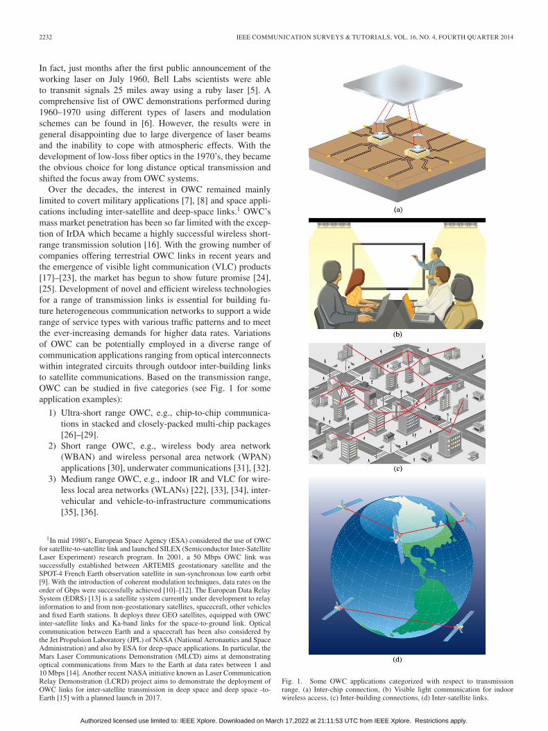
Over the decades, the interest in OWC remained mainlylimited to covert military applications [7], [8] and space appli-cations including inter-satellite and deep-space links.1 OWC’smass market penetration has been so far limited with the excep-tion of IrDA which became a highly successful wireless short-range transmission solution [16]. With the growing number ofcompanies offering terrestrial OWC links in recent years andthe emergence of visible light communication (VLC) products[17]–[23], the market has begun to show future promise [24],[25]. Development of novel and efficient wireless technologiesfor a range of transmission links is essential for building fu-ture heterogeneous communication networks to support a widerange of service types with various traffic patterns and to meetthe ever-increasing demands for higher data rates. Variationsof OWC can be potentially employed in a diverse range ofcommunication applications ranging from optical interconnectswithin integrated circuits through outdoor inter-building linksto satellite communications. Based on the transmission range,OWC can be studied in five categories (see Fig. 1 for someapplication examples):
1) Ultra-short range OWC, e.g., chip-to-chip communica-tions in stacked and closely-packed multi-chip packages[26]–[29].
2) Short range OWC, e.g., wireless body area network(WBAN) and wireless personal area network (WPAN)applications [30], underwater communications [31], [32].
3) Medium range OWC, e.g., indoor IR and VLC for wire-less local area networks (WLANs) [22], [33], [34], inter-vehicular and vehicle-to-infrastructure communications[35], [36].
1In mid 1980’s, European Space Agency (ESA) considered the use of OWCfor satellite-to-satellite link and launched SILEX (Semiconductor Inter-SatelliteLaser Experiment) research program. In 2001, a 50 Mbps OWC link wassuccessfully established between ARTEMIS geostationary satellite and theSPOT-4 French Earth observation satellite in sun-synchronous low earth orbit[9]. With the introduction of coherent modulation techniques, data rates on theorder of Gbps were successfully achieved [10]–[12]. The European Data RelaySystem (EDRS) [13] is a satellite system currently under development to relayinformation to and from non-geostationary satellites, spacecraft, other vehiclesand fixed Earth stations. It deploys three GEO satellites, equipped with OWCinter-satellite links and Ka-band links for the space-to-ground link. Opticalcommunication between Earth and a spacecraft has been also considered bythe Jet Propulsion Laboratory (JPL) of NASA (National Aeronautics and SpaceAdministration) and also by ESA for deep-space applications. In particular, theMars Laser Communications Demonstration (MLCD) aims at demonstratingoptical communications from Mars to the Earth at data rates between 1 and10 Mbps [14]. Another recent NASA initiative known as Laser CommunicationRelay Demonstration (LCRD) project aims to demonstrate the deployment ofOWC links for inter-satellite transmission in deep space and deep space -to-Earth [15] with a planned launch in 2017.
Fig. 1. Some OWC applications categorized with respect to transmissionrange. (a) Inter-chip connection, (b) Visible light communication for indoorwireless access, (c) Inter-building connections, (d) Inter-satellite links.
Authorized licensed use limited to: IEEE Xplore. Downloaded on March 17,2022 at 21:11:53 UTC from IEEE Xplore. Restrictions apply.

KHALIGHI AND UYSAL: SURVEY ON FREE SPACE OPTICAL COMMUNICATION: A COMMUNICATION THEORY PERSPECTIVE 2233
4) Long range OWC, e.g., inter-building connections.5) Ultra-long range OWC, e.g., inter-satellite links [37],
deep space links [14].
In this survey, we focus only on outdoor terrestrial OWC links(i.e., the fourth category), which are also widely referred to asfree space optical (FSO) communication in the literature. Thisterminology will be adopted hereinafter.
B. Advantages and Applications of FSO
FSO systems are used for high rate communication betweentwo fixed points over distances up to several kilometers. Incomparison to RF counterparts, the FSO link has a very highoptical bandwidth available, allowing much higher data rates.Terrestrial OWC products with transmission rates of 10 Gbpsare already in the market [38] and the speeds of recent ex-perimental OWC systems are competing with fiber optic [39]–[43]. FSO systems use very narrow laser beams. This spatialconfinement provides a high reuse factor, an inherent security,and robustness to electromagnetic interference. Furthermore,the frequency in use by the FSO technology is above 300 GHzwhich is unlicensed worldwide. Therefore, FSO systems donot require license fees [44]. FSO systems are also easilydeployable and can be reinstalled without the cost of dedicatedfiber optic connections.
FSO systems have initially attracted attention as an efficientsolution for the “last mile” problem to bridge the gap betweenthe end user and the fiber optic infrastructure already in place.Telecom carriers have already made substantial investments toaugment the capacity of their fiber backbones. To fully utilizethe existing capacity, and therefore to generate revenue, thisexpansion in the backbone of the networks should be accom-panied by a comparable growth at the network edge where endusers get access to the system. FSO systems are also appealingfor a wide range of applications some of which are elaboratedin the following [44]–[47] (see Fig. 2).
• Enterprise/campus connectivity: Today’s corporationsand school/university campuses are experiencing a hetero-geneous network traffic (i.e., voice, data, fax, multimediatraffic) that is overwhelming the typical connections. FSOsystems can bridge multiple buildings in corporate andcampus networks supporting ultra-high speeds without thecost of dedicated fiber optic connections.
• Video surveillance and monitoring: Surveillance cam-eras are widely deployed in commercial, law enforcement,public safety, and military applications. Wireless video isconvenient and easy to deploy, but conventional wirelesstechnologies fail to provide high throughput requirementsfor video streams. FSO technology presents a powerfulalternative to support high quality video transmission.
• Back-haul for cellular systems: Wireline connectionssuch as T1/E1 leased lines and microwave links are typ-ically deployed between the base stations and the mobileswitching center in a cellular system. The growing numberof bandwidth-intensive mobile phone services now re-quires the deployment of technologies such as FSO whichallow much higher throughput.
Fig. 2. Some typical applications of FSO: (a) An envisioned campus connec-tivity scenario where inter-building connections are enabled by high data rateFSO links. (b) High quality video surveillance and monitoring of a city canbe made possible by FSO links. (c) FSO links provide backhaul for cellularsystems. These are particularly useful for cases where fiber optic installment isexpensive or difficult to deploy.
• Redundant link and disaster recovery: Natural disasters,terrorist attacks, and emergency situations require flexibleand innovative responses. Temporary FSO links can bereadily deployed within hours in such disaster situations inwhich local infrastructure could be damaged or unreliable.A tragic example of the FSO deployment efficiency as aredundant link was witnessed after 9/11 terrorist attacks inNew York City. FSO links were rapidly deployed in thisarea for financial corporations which were left out with nolandlines.
Authorized licensed use limited to: IEEE Xplore. Downloaded on March 17,2022 at 21:11:53 UTC from IEEE Xplore. Restrictions apply.

2234 IEEE COMMUNICATION SURVEYS & TUTORIALS, VOL. 16, NO. 4, FOURTH QUARTER 2014
• Security: Today’s cryptosystems are able to offer onlycomputational security within the limitations of conven-tional computing power and the realization of quantumcomputers would, for example, make electronic moneyinstantly worthless. Based on the firm laws of physics,quantum cryptography provides a radically different so-lution for encryption and promises unconditional security.Quantum cryptography systems are typically consideredin conjunction with fiber optic infrastructure. FSO linksprovide a versatile alternative in cases where the fiber opticdeployment is costly and/or infeasible.
• Broadcasting: In broadcasting of live events such assports and ceremonies or television reporting from re-mote areas and war zones, signals from the camera (or anumber of cameras) need to be sent to the broadcastingvehicle which is connected to a central office via satelliteuplink. The required high-quality transmission betweenthe cameras and the vehicle can be provided by a FSOlink. FSO links are capable of satisfying even the mostdemanding throughput requirements of today’s high def-inition television (HDTV) broadcasting applications. Forexample, during 2010 FIFA World Cup, UK TV stationBBC deployed FSO links for Ethernet-based transport ofhigh definition video between temporary studio locationsset up in Cape Town, South Africa.
Currently, there are several companies which are working onthe design and manufacturing of FSO systems as outdoor wire-less transmission solutions such as Canon (Japan), Cassidian(Germany), fSONA (Canada), GeoDesy (Hungary), Laser ITC(Russia), LightPointe Communications (USA), MRV (USA),Northern Hi-Tec (UK), Novasol (USA), Omnitek (Turkey),Plaintree Systems (Canada), and Wireless Excellence (UK)among others.
II. FSO CHANNEL MODELING
The optical power launched from the transmitter is af-fected by various factors before arriving at the receiver. Theseinclude system loss, geometric loss, misalignment loss, at-mospheric loss, atmospheric turbulence induced fading, andambient noise. The system loss highly depends on the designspecifications and is usually specified by the manufacturers.Details on the system loss can be found in [48]. In the following,we provide further details on the other factors.
A. Geometric and Misalignment Losses
The geometric loss is due to the divergence of the beam whenpropagating through the atmosphere. It can be calculated giventhe divergence angle, the link distance, and the receiver lensaperture size. In calculating the geometric loss, an importantfactor is the optical wave propagation model. For horizontal FSOtransmissions, a good approximation is to consider a Gaussianprofile for the beam intensity [49]. When a Gaussian beam hasa relatively large divergence, its statistical properties are closeto the case of a point source [50]. In such a case, the approxi-mations of plane or spherical wave can effectively be used.
The degree of beam divergence also affects transmitter-receiver alignment and beam tracking at the receiver. Misalign-
ment occurs in practice mostly due to beam wander, buildingsway, or errors in the tracking system. Beam wander is theresult of inhomogeneities of large-scale atmosphere eddies thatcause random deflections of the optical beam, and as a result,the beam deviates from its original path [51]–[55]. This phe-nomenon is in particular important for long distance paths. Onthe other hand, building sway is the result of a variety of factors,including thermal expansion, wind loads, small earthquakes,and vibrations [56], [57]. Because of the narrowness of thetransmitted beam and the usually small receiver field of view(FOV), building sway can effectively cause a communicationinterrupt [48], [58].
When no tracking mechanism is used at the receiver side,which is typically the case for entry model FSO links with arange of several hundred meters, the misalignment loss can bealleviated by increasing the beam divergence at the transmitter.The use of spatially partially coherent Gaussian beams has beenfurther proposed in [59]–[61] to mitigate the misalignment-induced pointing errors. It was shown in [57] that beamoptimization allows significant gains in the channel capacity.Similar studies [54], [62] showed that the transmitter beamradius can be optimized to maximize the average link capacityand to minimize the outage probability (see Section IV). De-ployment of variable wavelengths by using quantum cascadelasers is also proposed in [63] to mitigate the effect of buildingsway. For long distances (i.e., more than one kilometer), as anarrower beam should be used to avoid suffering from a highgeometric loss, the use of automatic pointing and tracking atthe receiver becomes necessary to remove or reduce the effectsof pointing errors [48].
Statistical modeling of the pointing errors and its impacton the system performance has been studied in several recentworks. Under the assumption that the building sway statisticsfollow an independent Gaussian distribution for elevation andfor horizontal directions, the radial pointing error angle ismodeled by a Rayleigh distribution in [56], [63], [64]. Thecombined effect of pointing errors and atmospheric turbulence(see Section II-C) has been further studied in several works.In [57], it is proposed to consider the random attenuation ofthe channel as the product of path loss, geometric spread andpointing errors, and atmospheric turbulence. Also, consideringa Gaussian beam profile and Rayleigh distributed radial dis-placement at the receiver, a statistical model is derived for themisalignment loss that takes the detector size, beam width, andjitter variance into account. The same model was used in [65]to study the effect of pointing errors on the FSO link capacity.Also, an analytical expression for the average bit-error-rate(BER) is derived in [66], [67], and the performance of codedFSO links is studied in [68]. The effect of pointing errors on theperformance of space-diversity and relayed FSO systems (seeSections VII and IX) has also been considered in [69]–[71] and[72], respectively.
B. Atmospheric Loss
The physics and the transmission properties of the radiationpenetrating the atmosphere are very similar in the visible andthe near-IR wavelength ranges. Therefore, visibility can be used
Authorized licensed use limited to: IEEE Xplore. Downloaded on March 17,2022 at 21:11:53 UTC from IEEE Xplore. Restrictions apply.

KHALIGHI AND UYSAL: SURVEY ON FREE SPACE OPTICAL COMMUNICATION: A COMMUNICATION THEORY PERSPECTIVE 2235
to characterize particles that absorb or scatter light for near-IRradiations as well. The particles affecting the visibility includerain, snow, fog, but also pollution, dust, aerosols, smoke, etc.They absorb to some degree the laser light energy, causing anattenuation of the optical power. In near-IR, absorption occursprimarily due to water particles [47], [73]–[76]. They causelight scattering, which is the deflection of incident light from itsinitial direction, causing spatial, angular, and temporal spread.For rain and snow, the size of the particles is much largerthan the wavelength, and consequently, the FSO transmissionis relatively unaffected [77]. In the case where FSO systems aredeployed in metropolitan areas over distances less than 1 km,typical rain attenuation values are typically on the order of3 dB/km. Only for very severe rain, the attenuation can becomean issue in deployments beyond the distance scale of a typicalmetropolitan area [74], [78]. For snow, the attenuation can bemore severe than rain due to a much larger droplet size. Infact, the impact of light snow to blizzard falls approximatelybetween light rain to moderate fog (see below) [74], [79].
When the particle diameter is on the order of the wavelength,the resulting scattering coefficient is very high. That is why themost detrimental environmental conditions are fog and haze[47], [73], [74], [80] as they are composed of small particleswith radii close to the near-IR wave lengths. Even modestfog conditions can highly attenuate IR signals over shorterdistances. Experimental tests have reported about 90% loss inthe transmit power over a distance of 50 m in moderate fog [74].Channel modeling for FSO communication through fog is stud-ied in [58], [77], [81]. The experimental measurements in [80]revealed that the atmospheric attenuation is almost independentof the wavelength between 785 and 1550 nm for fog, but itis wavelength dependent in haze conditions [80]. Typically,haze particles have a size between 0.01 and 1 μm, whereasfog droplets have radius between 1 to 20 μm, and hence, thebeam light suffers from less attenuation in haze conditions [80].Also, different scatterer sizes result in wavelength dependenceof light extinction in haze and dense fog conditions [82]. Adetailed analysis based on the Mie scattering theory is presentedin [82] where a wavelength dependent model for the attenuationcoefficient is proposed for fog and haze situations.
An interesting point to note is that RF wireless technologiesthat use frequencies above approximately 10 GHz are adverselyimpacted by rain and little impacted by fog [74], [78]. Thismotivates the design of hybrid RF/FSO systems which will belater discussed in Section X.
An important consideration in FSO channel modeling is thechannel coherence bandwidth which is defined as the inverseof the channel delay spread [83]. Whereas under clear weatherconditions, the FSO channel has a negligible delay spread [84],fog, moderate cloud, and rain can potentially result in temporalbroadening of optical pulses. This, in turn, results in inter-symbol interference (ISI) and degrades the system performance[85]. However, given the typical data rates of FSO links, thechannel delay spread as a result of beam scattering due tofog or rain is practically negligible. This is shown recentlyin [86] where numerical Monte Carlo-based simulations areused to quantify the channel root mean square (RMS) delayspread. In particular, the RMS delay spread due to rain under
realistic conditions is less than 10 picoseconds for a 1 kmlink. Also, under moderate and dense fog, the delay spread istypically limited to 50 picoseconds [86]. Consequently, in anycase, the channel can effectively be considered as frequencynon-selective, introducing no ISI.
C. Atmospheric Turbulence Induced Fading
Under clear atmosphere conditions, the atmospheric loss as-sociated with visibility is negligible, but we are faced to anotheradverse effect known as scintillation or fading. Inhomogeneitiesin the temperature and the pressure of the atmosphere, causedby solar heating and wind, lead to the variations of the airrefractive index along the transmission path [51], [87]. Theresulting atmospheric turbulence causes random fluctuations inboth the amplitude and the phase of the received signal, i.e.,channel fading. This results in a considerable degradation of thesystem performance, especially in long-distance transmissionsof about several kilometers [51], [88].
A comprehensive study of turbulence modeling for terrestrialFSO links can be found in [51].2 Atmospheric turbulence ismainly characterized by three parameters: the inner and theouter scales of turbulence denoted respectively by l0 and L0,and the index of refraction structure parameter C2
n, some-times called the turbulence strength [88]. According to theKolmogorov theory, L0 is the largest cell size before the energyis injected into a region and l0 is associated with the smallestcell size before energy is dissipated into heat [51], [90]. Theenergy distribution of the turbulence cells can be describedby the spatial power spectrum of refractive-index fluctuations.Kolmogorov and Tarascii models are two spectra that areusually considered [87]. For moderate to strong turbulenceregimes, a modified spectrum is used by considering two spatialfilters which remove the contribution of the turbulent eddies ofsize between the coherence radius and the scattering disc [51],[91]. Usually, the outer scale is approximated as L0 → ∞ as ithas a negligible impact on turbulence in practice [88]. On theother hand, the inner scale l0 has a significant impact on the tur-bulence [92]; in particular, larger values of l0 result in a higherirradiance variance in the strong turbulence regime [93], [94].
The refraction structure parameter C2n is altitude dependent
and is larger at lower altitudes due to the more significantheat transfer between the air and the surface [88]. In general,it also depends on the link distance [95]. However, usuallythe conditions of homogeneous turbulence are considered interrestrial FSO systems and it is assumed that C2
n does notdepend on distance. Typical values for C2
n vary from 10−17 to10−13 m−2/3 [96]. Its variations can be extremely importantduring daytime at a given location that can attain four orders ofmagnitude [97]. On the other hand, it becomes almost constantat night [98] and its dependence on height decreases, comparedwith daytime [97]. At near ground level, C2
n has its peak valueduring midday hours whereas its minima occur near sunrise andsunset [98]. An important question is how the meteorologicalconditions affect the refraction structure parameter. In [99],
2Turbulence modeling in over-water and coastal environments can be foundin [89].
Authorized licensed use limited to: IEEE Xplore. Downloaded on March 17,2022 at 21:11:53 UTC from IEEE Xplore. Restrictions apply.

2236 IEEE COMMUNICATION SURVEYS & TUTORIALS, VOL. 16, NO. 4, FOURTH QUARTER 2014
experimental models were proposed to predict C2n according
to the weather forecast. The performed measurements showthat scintillation is affected by aerosols, particularly when theirtotal cross-sectional area is relatively large. Similar studies arepresented in [89], [96], and tables reporting C2
n for differentweather conditions can be found in [73], [100].
To quantify the fluctuations resulting from atmospheric tur-bulence, the scintillation index (SI) is frequently used in theliterature. It is defined as σ2
I = E{I2}/E{I}2 − 1 [101], whereI is the intensity of the received optical wave and E{.} de-notes the expected value. While SI provides a characterizationof the turbulence strength based on the first and the secondmoments of the intensity, full statistical characterization hasbeen further investigated in the literature and several statisticalchannel models have been proposed for the distribution ofturbulence-induced fading in FSO systems. The most widelyaccepted model under weak turbulence conditions is the log-normal model. This model was derived based on the first-orderRytov approximation several decades ago [51], [101], [102].It applies to the FSO systems deployed over relatively shortranges in urban areas and has been considered in several workssuch as [103]–[105]. However, experimental data over longpropagation paths have shown that the log-normal model isnot appropriate for moderate-to-strong turbulence regime [88],[106]–[110]. The negative exponential distribution is a limitdistribution for the intensity in the saturation regime [110]and is used in several works considering strong turbulenceconditions [105], [111]–[114]. The Rayleigh distribution hasbeen used in [115] to model limiting cases of severe atmo-spheric turbulence. The K distribution, originally proposed asa model for non-Rayleigh sea clutter, has also been used for thestrong turbulence regime [116]. The probability density func-tion (PDF) of the received intensity I by this model is given by:
p(I) =2α
Γ(α)(αI)
α−12 Kα−1(2
√αI), I > 0, α > 0, (1)
where Km(.) is the modified Bessel function of second kindand order m, and the parameter α determines the SI byσ2I = 1 + 2/α.Over the years, there have been significant efforts to establish
a universal model that is applicable to any type of turbulenceconditions. These efforts mainly rely on the use of doublystochastic theory of scintillation in which the large- and small-scale turbulence eddies are supposed to induce refractive anddiffractive effects on the light beam, respectively [51]. Par-ticularly, Andrews and Phillips [117], [118] extended the Kdistribution to the case of weak turbulence by proposing thedoubly-stochastic I-K distribution. However, it was later notedin [108] that the I-K model deviates from the experimental data.Other distributions such as log-normally-modulated exponen-tial, exponentiated Weibull, and log-normal Rice (also knownas Beckmann) have been further proposed [109], [110], [119],[120]. In particular, the log-normal, log-normal exponential andexponential distributions can be considered as special cases ofthe log-normal Rice model [121]. Another doubly-stochasticscintillation model is the Gamma-Gamma distribution [51],[110] which has gained a wide acceptance in the current litera-
ture. In the Gamma-Gamma model, the received intensity I isconsidered as the product of two independent Gamma randomvariables X and Y , which represent the irradiance fluctuationsarising from large- and small-scale turbulence, respectively.The PDF of I is:
p(I) =2(ab)
(a+b)2
Γ(a) Γ(b)I(a+b)/2−1Ka−b(2
√abI), I > 0, (2)
where the parameters a and b represent the effective numbers oflarge- and small-scale turbulence cells, and Γ(.) is the Gammafunction. Also, the SI by this model is given by σ2
I = (1/a) +(1/b) + (1/ab).
The Double Weibull distribution is another doubly-stochasticmodel for atmospheric turbulence channels that has been shownto be more accurate than the Gamma-Gamma model, particu-larly for the cases of moderate and strong turbulence [122]. TheM-distribution is another recent model that includes most ofthe already proposed statistical models, e.g., K and Gamma-Gamma, as special cases [123], [124]. One of the latest at-tempts in atmospheric turbulence modeling based on the doublystochastic theory is reported in [125] which proposes the Dou-ble Generalized Gamma (Double GG) model, which is slightlymore accurate than Double Weibull. The superiority of DoubleGG over Gamma-Gamma is particularly obvious in the strongturbulence when considering the spherical wave propagationmodel, as well as in the moderate turbulence regime consideringplane wave propagation.
In addition to modeling the intensity fluctuations, an impor-tant point is the temporal characterization of turbulence. In mostpractical cases, the channel fading is very slowly varying andthe channel coherence time is typically 0.1 to 10 ms [44]. Asin FSO systems we are concerned with very high transmissionrates on the order of several tens of Mpbs to several Gbps,the channel fading coefficient remains constant over thousandsup to millions of consecutive bits. Therefore, the quasi-staticchannel fading model [83] applies to FSO links.
As implicitly mentioned above, the beam (wave) modelcan also impact the effect of atmospheric turbulence. Generalbeam types, namely Gaussian, cos-Gaussian, cosh-Gaussian,and annular beams are compared in [126]. The three latter canbe considered as general beam shapes, which can reduce tosimpler models such as plane and spherical propagation modelsor the classical Gaussian beam model by setting some specificparameters [127], [128]. It is shown that for small source sizesand when transmitting over long propagation distances, the bestperformance is obtained for annular beams [126], [129]. On theother hand, for relatively large source sizes and when trans-mitting over short propagation distances, the best performanceis achieved using cos-Gaussian beams. Furthermore, higher-order beams provide better performances than the zero-orderbeams at longer propagation distances [126]. In [130], the flat-topped Gaussian beam is studied, which can be represented asa superposition of several Gaussian beams of different scales.It is shown in particular that the turbulence effect reduces byusing flat-topped Gaussian beams, compared to single Gaussianbeams, for source sizes much larger than the first Fresnelzone [130]. However, except for very small and very large
Authorized licensed use limited to: IEEE Xplore. Downloaded on March 17,2022 at 21:11:53 UTC from IEEE Xplore. Restrictions apply.

KHALIGHI AND UYSAL: SURVEY ON FREE SPACE OPTICAL COMMUNICATION: A COMMUNICATION THEORY PERSPECTIVE 2237
source sizes, the effect of turbulence increases by increasing thenumber of Gaussian beams used for flattening out the overallbeam profile [131].
D. Background Radiation
Last but not least, background radiation, also called back-ground noise or ambient noise, can degrade the performance ofFSO links. In fact, in addition to the useful signal, the receiverlens also collects some undesirable background radiations thatmay consist of direct sunlight, reflected sunlight, or scatteredsunlight from hydrometeor or other objects [48], [132]–[135].Their effect can be reduced by means of narrow spectral band-pass and spatial filtering, prior to photo-detection. Nevertheless,a non-negligible background noise may fall within the spatialand frequency ranges of the detector that can limit the systemperformance by causing a variable offset in the converted elec-trical signal [133]. This, in turn, results in a reduced signal-to-noise ratio (SNR) [136] and effective receiver sensitivity [134].In some circumstances, background radiation can even causelink outages because of the saturation of the receiver [133].
In the (theoretical) case of a diffraction-limited receiver, thereceived background noise level is independent of the receiveraperture size [132], [137]. In practice, an FSO receiver usesa lens and a photo-detector of a given size and, hence, hasa FOV much larger than the diffraction limit. In fixed FOVreceivers, the background noise power is proportional to thereceiver pupil area [132]. Experimental measurements indicatethat while the received optical signal power is typically abouttens to hundreds of μW, the background radiation power is inthe range of several μW for scattered sunlight by clouds or fog,about hundreds of μW for reflected sunlight, and up to about10 mW for direct sunlight [135]. This latter case can statisti-cally occur less than 1 hour per year, however.
Background noise can be statistically modeled by a Poissonrandom process [133], [138]. When the background radiationlevel is relatively high, the average number of the correspondingreceived photons is large enough to allow the approximationof the Poisson distribution by a Gaussian distribution [138].Since the mean value of the background noise is rejected bythe ac-coupled receiver circuitry, the noise has zero mean.Furthermore, the contributions from the interaction of the signalwith background radiations due to the non-linear characteristicof the photo-detector [132] can practically be neglected [139],and a signal-independent Gaussian model can be used.
III. FSO TRANSCEIVER
In an FSO communication system, a source produces infor-mation waveforms which are then modulated onto an opticalcarrier. The generated optical field is radiated through theatmosphere towards a remote destination. At the receiver, thefield is optically collected and a photo-detector transformsthe optical field to an electrical current. The receiver processesthe detected electrical current to recover the original transmittedinformation.
Current FSO systems typically operate in the near-IR wave-lengths, i.e., from 750 to 1600 nm. Although the (clear) at-mosphere is considered as highly transparent in the near-IR
Fig. 3. The general block diagram of the transmitter.
wavelength range, certain wavelengths can experience severeabsorption due to the presence of different molecules in theatmosphere [48]. For some special wavelength windows, lo-cated around four specific wavelengths of 850, 1060, 1250, and1550 nm, an attenuation of less than 0.2 dB/km is experienced[140]. Interestingly, the 850 and 1550 nm windows coincidewith the standard transmission windows of fiber communi-cation systems. That is why most of commercially availableFSO systems operate at these two windows so as to usethe corresponding available off-the-shelf components. Otherwavelengths such as 10 μm [48], [141] and UV wavelengths[142] have been recently considered for FSO systems. The10 μm wavelength is known to have better fog transmissioncharacteristics [48]. UV transmissions, on the other hand, aremore robust against pointing errors and beam blockage andhave a lower sensitivity to solar and other background inter-ferences [142].
A. Transmitter
As illustrated in Fig. 3, the transmitter consists of an opticalsource, a modulator, an optical amplifier (if required), and beamforming optics. Channel coding can be optionally used beforemodulation (see Section VI). Data bits from the informationsource are first encoded, then modulated. The modulated laserbeam is then passed through the optical amplifier to boost theoptical intensity. The light beam is collected and refocused bymeans of beam forming optics before being transmitted.
The typical optical source in FSO systems is a semiconductorlaser diode (LD) [34], although some manufacturers use highpower LEDs with beam collimators [143]. The optical sourceshould deliver a relatively high optical power over a widetemperature range. Moreover, it should have a long mean timebetween failures (MTBF) and the corresponding componentsshould be small in footprint and have low power consump-tion [48], [140]. Consequently, vertical-cavity surface-emittinglasers (VCSEL) are mostly used for operation around 850 nm,and Fabry-Perot (FP) and distributed feedback (DFB) lasers aremostly used for operation at 1550 nm.
An important factor for laser transmitters is the safety issues.The primary safety concern is the potential exposure of the eyeto the laser beam. Several standards have been developed tolimit the transmitted optical power, which rely on parameterssuch as the laser wavelength and the average and peak trans-mission power [144]. In fact, only certain wavelengths in thenear-IR wavelength range can penetrate the eye with enoughintensity to damage the retina. Other wavelengths tend to be ab-sorbed by the front part of the eye before the energy is focusedon the retina. In fact, the absorption coefficient at the front partof the eye is much higher for longer wavelengths (> 1400 nm)[48], [144]. For this reason, the allowable transmission power
Authorized licensed use limited to: IEEE Xplore. Downloaded on March 17,2022 at 21:11:53 UTC from IEEE Xplore. Restrictions apply.

2238 IEEE COMMUNICATION SURVEYS & TUTORIALS, VOL. 16, NO. 4, FOURTH QUARTER 2014
Fig. 4. Coherent FSO receiver block diagram.
Fig. 5. IM/DD FSO receiver block diagram.
for lasers operating at 1550 nm is higher [145], and hence, theyare considered for longer distance transmissions.
B. Receiver
FSO systems can be broadly categorized into two classesbased on the detection type: non-coherent and coherent. Incoherent systems (Fig. 4), amplitude, frequency, or phase mod-ulation can be used. At the receiver side, the received field isoptically mixed before photo-detection with a locally generatedoptical field.
In non-coherent systems (Fig. 5), the intensity of the emittedlight is employed to convey the information. At the receiverside, the photo-detector directly detects changes in the lightintensity3 without the need for a local oscillator. These sys-tems are also known as intensity-modulation direct-detection(IM/DD) systems. Although coherent systems offer superiorperformance in terms of background noise rejection, mitigat-ing turbulence-induced fading, and higher receiver sensitivity[44], [148]–[150], IM/DD systems are commonly used in theterrestrial FSO links due to their simplicity and low cost. In thefollowing, we will focus on IM/DD systems while a discussionon advances in coherent FSO systems is provided in Section XI.
The receiver front-end in an IM/DD FSO systems consistsof optical filters and a lens which has the role of collectingand focusing the received beam onto the photodiode (PD). ThePD output current is next converted to a voltage by means ofa trans-impedance circuit, usually a low-noise Op-Amp with aload resistor. This latter is determined based on the transmissionrate, the dynamic range of the converted electrical signal, thegenerated receiver thermal noise, and impedance matching with
3The number of absorbed photons by the photo-detector and the generatedelectrons after photo-detection are random in nature [132]. Classically, thephoton-counting model has been used for the received signal in OWC systems,where the received signal was modeled by a Poisson random process [104],[111], [112], [132], [146], [147]. However, this signal model is mostly useful indeep space applications where usually a photon-counting receiver is employeddue to too small number of received photons [14]. In the context of terrestrialFSO systems used over ranges up to several kilometers, however, the receivedphoton flux is usually important enough to allow working with the beam inten-sity directly. Even, photon counting is not feasible in practice. Nevertheless, thereceived signal intensity is proportional to the number of received photons.
the other receiver parts. It is typically about several hundreds ofkΩ in deep-space applications [151] down to about 50–100 Ωin high-rate terrestrial FSO links [152]. The output of the trans-impedance circuit is then low-pass filtered in order to limit thethermal and background noise levels.
Concerning the PD, solid-state devices are mostly used incommercial FSO systems since they have a good quantumefficiency for the commonly used wavelengths [132], [153].The junction material can be of Si, InGaAs, or Ge, which areprimarily sensitive to the commonly used wavelengths and havean extremely short transit time, which leads to high bandwidthand fast-response detectors [132]. Si PDs have a maximumsensitivity around 850 nm, whereas InGaAs PDs are suitablefor operation at longer wavelengths around 1550 nm. Ge PDsare rarely used, however, because of their relatively high levelof dark current [48].
The solid state PD can be a P-i-N (PIN) diode or an avalanchephotodiode (APD). PIN diodes are usually used for FSO sys-tems working at ranges up to a few kilometers [154]. Themain drawback of PIN PDs is that the receiver performancebecomes very limited by the thermal noise. For long distancelinks, APDs are mostly used which provide a current gainthanks to the process of impact ionization. The drawback ofAPDs, in turn, is the excess noise at their output, which modelsthe random phenomenon behind the generation of secondaryphoto-electrons. Due to this reason, the APD gain is usuallyoptimized with respect to the received signal power in orderto maximize the received SNR [155]. The advantage of APDcomes at the expense of increased implementation complex-ity. In particular, we need a relatively high voltage for APDreverse biasing that necessitates the use of special electroniccircuits. This also results in an increase in the receiver powerconsumption.
The use of optical pre-amplifiers has also been proposedin long range FSO links to improve their performance [156],[157]. In the 1550 nm wavelength, an Erbium-doped fiberamplifier (EDFA) is a good choice. Semiconductor optical am-plifiers (SOAs) can also be used in a variety of wavelengths (in-cluding 1550 nm). However, apart from the problems associatedwith coupling to the receiver optics, especially when using amultimodal fiber, the optical amplifier introduces an amplified
Authorized licensed use limited to: IEEE Xplore. Downloaded on March 17,2022 at 21:11:53 UTC from IEEE Xplore. Restrictions apply.
KHALIGHI AND UYSAL: SURVEY ON FREE SPACE OPTICAL COMMUNICATION: A COMMUNICATION THEORY PERSPECTIVE 2239
spontaneous emission (ASE) noise, usually modeled as additivewhite Gaussian noise (AWGN), which can degrade the receiverperformance [138]. More specifically, in direct detection re-ceivers, an optical pre-amplifier can degrade the SNR by atleast 3 dB [153]. Nevertheless, when the receiver performanceis limited by the electronic noise (see the following subsection),optical pre-amplification can be highly beneficial [153]. Theuse of an EDFA or an SOA when gain-saturated by the inputsignal has also been proposed to reduce the scintillation effectin the weak turbulence regime [158].
C. Receiver Noise and Modeling
The noise sources at the receiver [132], [138], [159] consistof the PD dark current, the transmitter noise, thermal noise, andthe photo-current shot-noise (which arises from input signaland/or background radiations). The PD dark current can beneglected for most practical purposes. The transmitter noisearises from the instability of the laser intensity and the resultingfluctuations of the photo-current at the receiver, which aremodeled by considering the so-called laser relative intensitynoise (RIN) [138]. However, RIN has usually a negligible effecton the receiver performance [139].
If the background illumination level is negligible, the twomain noise sources affecting the receiver are thermal and shotnoises. A PIN-based receiver is usually thermal-noise limited.On the other hand, APD-based receivers are usually shot-noise-limited except for relatively small values of the loadresistor where the thermal noise also affects the performance[139]. Thermal noise originates from the receiver electroniccircuitry, mainly the load resistor, and is modeled as a zero-mean Gaussian random process. On the other hand, shot noise,also called the quantum noise, arises from random fluctuationsof the current flowing through the PD and is modeled by aPoisson process. In the case of using a PIN PD, if the meannumber of absorbed photons is relatively large, the shot noisecan be approximately modeled by a Gaussian process [138]. Inmost FSO applications, the received photon flux is high enoughto allow this approximation. In the case of using an APD, onthe other hand, the distribution of the number of generated elec-trons is given by McIntyre in [160, (16a)] and experimentallyverified by Conradi in [161]. However, it has been shown in[139], [162] that this distribution can be approximated by aGaussian. So, whatever the PD type, the receiver shot noise canbe modeled as Gaussian distributed. Notice that this is also truewhen background radiations cannot be neglected [103], [105],[113], [121], [132], [163]–[165].
IV. INFORMATION THEORETICAL LIMITS
The Shannon-Hartley theorem determines the (theoretical)maximum data rate that can be transmitted with an arbitrarilysmall BER over a channel for a given average signal power[166]. This maximum achievable rate is known as channelcapacity. Numerous works have considered the capacity of a“classical” optical channel, i.e., in the absence of turbulence.The earliest works have considered a Poisson channel modelfor the quantum-noise limited receivers, assuming negligiblethermal and background noise. It was shown in [167], [168] that
the capacity of these photon counting receivers (in nats/photon)under an average optical power constraint is unbounded. Insuch channels, the Q-ary pulse position modulation (PPM) (seeSection V) can achieve arbitrarily small probability of errorfor any rate [169], [170]. Under an additional constraint offixed peak optical power, it was shown in [171], [172] thatbinary level modulation schemes are capacity-achieving. Thecapacity of a PPM channel was also studied in [173] for thecase of deep-space communication using a photon countingreceiver. Also, [151] studied the capacity of the PPM channelassuming a receiver with an APD. Nevertheless, PPM-basedphoton counting schemes require an exponential increase inbandwidth as a function of the rate [169]. To avoid the needto increased bandwidth, one solution is to use pulse amplitudemodulation (PAM) and to increase the corresponding numberof levels [174]. These general conclusions are also valid for thecase of FSO links affected by background and thermal noises,where the noise is modeled as Gaussian distributed [175].
In practice, as FSO channels are subject to atmosphericturbulence, the channel capacity should be considered as arandom variable due to the randomness of the channel fadingcoefficient [176]. In general, for channels subject to fading,the definitions of ergodic or outage capacities are used [177].Ergodic (also called average) capacity is the expectation of theinstantaneous channel capacity and is useful when the channelvaries very fast with respect to the symbol duration [178].The ergodic capacity can be calculated through the expectationof the mutual information expression with respect to randomfading coefficients. For FSO channels where the channel co-herence time is relatively large, the outage capacity becomesmore meaningful [92]. In this case, communication is declaredsuccessful if the mutual information exceeds the informationrate. Otherwise, an outage event is declared. The probability ofan outage event is commonly referred to as outage probabilityor the probability of fade. Based on this outage definition,θ-outage capacity is the largest rate of transmission such thatthe outage probability is less than θ, where the value of θdepends on the intended application. Note that another defi-nition of channel capacity that has been proposed for fadingchannels is the delay-limited capacity, which corresponds tothe zero-outage capacity, i.e., the capacity conditioned to azero outage probability [177]. For a turbulent channel, whenno diversity technique is employed, the delay-limited capacityequals zero, and at the limit of infinite diversity order, it tendsto the ergodic capacity [113], [177]. Similar to ergodic capacity,this definition is not useful in the case of FSO channels and theoutage capacity is quite more appropriate for these channels.
Several works have investigated the capacity of turbulentFSO channels. The ergodic capacity of an FSO link was studiedin [179]–[181] for the cases of log-normal, Gamma-Gamma,negative exponential, and I-K fading models and consideringthe AWGN model for the receiver noise. Outage capacity ofI-K fading channels with AWGN was also studied in [182]while the outage probability is investigated under the assump-tion of a log-normal fading channel in [88] and for a Gamma-Gamma channel in [110]. Other works have considered FSOsystems with transmit and/or receive diversity (see Section VII).For instance, outage capacity for aperture averaging and multiple
Authorized licensed use limited to: IEEE Xplore. Downloaded on March 17,2022 at 21:11:53 UTC from IEEE Xplore. Restrictions apply.

2240 IEEE COMMUNICATION SURVEYS & TUTORIALS, VOL. 16, NO. 4, FOURTH QUARTER 2014
TABLE ILITERATURE ON FSO CHANNEL CAPACITY. LN, ΓΓ, AND EXP STAND FOR LOG-NORMAL, GAMMA-GAMMA, AND
EXPONENTIAL FADING MODELS, RESPECTIVELY
aperture receivers was studied in [92] considering Gamma-Gamma fading and AWGN at the receiver. For instance,considering Gamma-Gamma modeled strong turbulence withRytov variance 19.18, background-noise-limited receiver, un-coded OOK modulation, an outage probability of 10−9, and amoderate average received SNR of 15 dB, the outage capacityof an FSO system increases from 0.05 to 0.86 bit/symbol byincreasing the receiver aperture diameter from 20 to 100 mm,respectively [92]. Under the same conditions, for a four-aperture FSO system of aperture diameter 10 and 50 mm (withthe same total receiver aperture size as for the SISO case), theoutage capacity equals 0.61 and ∼1 bit/symbol, respectively.
The outage probability of MIMO FSO systems was alsoderived in [113], [121] for AWGN model and different channelmodels including exponential, log-normal, Gamma-Gamma,log-normal Rice, and I-K fading. Ergodic and outage capacitiesof a MIMO Poisson channel subject to log-normal fading werealso studied in [183], and the ergodic MIMO capacity wasstudied in [184] for the case of a PIN-based receiver assumingAWGN and Gamma-Gamma fading. Lastly, the outage andergodic capacities of FSO systems with pointing errors werestudied in [57] and [185]–[187], respectively, for the case ofGamma-Gamma fading and AWGN model.
Table I summarizes the contribution of the most relevantworks in the literature by specifying the considered capacitydefinitions and channel models.
V. MODULATION
The most commonly used IM technique due to its imple-mentation simplicity is on-off keying (OOK), which is a binarylevel modulation scheme. In OOK signaling, modulated data isrepresented by the presence (“on”) or absence (“off”) of a lightpulse in each symbol interval. At the receiver, for optimal signaldetection, we need to know the instantaneous channel fadingcoefficient to perform dynamic thresholding [188]. The channelstate information (CSI) can be estimated with good accuracyby using a few pilot symbols in practice [189]. Alternative so-lutions include symbol-by-symbol maximum likelihood (ML)detection based on the availability of distribution of the channel
fading (not the full knowledge of the instantaneous channelfading coefficient) [103] and ML sequence detection based onthe knowledge of the joint temporal statistics of the fading[163]. In addition to the need to dynamic thresholding at the re-ceiver, OOK has relatively poor energy and spectral efficiency.Indeed, these are two important factors relative to the choice ofa modulation scheme. Energy efficiency refers to the maximumachievable data rate at a target BER (or the minimum BER at atarget data rate) for a given transmit energy irrespectively of theoccupied bandwidth. As its definition indicates, in particular, itdoes not take into account the increase in the switching speedof the electronics that can be an important point regarding theimplementation complexity. Spectral or bandwidth efficiency,on the other hand, refers to the information transmission rate fora given bandwidth without taking the required transmit energyinto account.
Several other IM schemes have been proposed to overcomesome disadvantages. To address energy efficiency, PPM be-comes a powerful solution [104]. It is shown in [172] that,for a classic optical channel under peak and average powerconstraints, a slotted binary modulation can nearly achieve thechannel capacity. Furthermore, it is proved in [132] that, undersuch constraints, PPM can attain the near-optimum channelcapacity. When performing hard signal detection at the receiver,PPM has the advantage that, in contrast to OOK, it doesnot require dynamic thresholding for optimal detection [111],[190], [191]. PPM is in particular proposed for deep space com-munication (together with photon-counting receivers), whereenergy efficiency is a critical factor [14], [192].
In comparison to PPM, multipulse PPM (MPPM) brings thefurther advantages of having a reduced peak-to-average powerratio (PAPR) and a higher spectral efficiency [193], [194] whileit has an increased demodulation complexity [190]. Note that,although there is a large bandwidth available in the optical band,spectral efficiency is still an important design considerationsince it is directly related to the required speed of the electroniccircuitry in an FSO system from a practical point of view. Undera constraint on the peak transmit power, MPPM outperformsPPM. Conversely, when a constraint is imposed on the averagetransmit power, PPM outperforms MPPM [193], [195].
Authorized licensed use limited to: IEEE Xplore. Downloaded on March 17,2022 at 21:11:53 UTC from IEEE Xplore. Restrictions apply.

KHALIGHI AND UYSAL: SURVEY ON FREE SPACE OPTICAL COMMUNICATION: A COMMUNICATION THEORY PERSPECTIVE 2241
TABLE IILITERATURE ON FSO SIGNAL MODULATION
Two other well-known modulation schemes are pulse widthmodulation (PWM), and digital pulse interval modulation(DPIM). Compared with PPM, PWM requires a lower peaktransmit power, has a better spectral efficiency, and is more re-sistant to ISI, especially for a large number of slots per symbol(Q) [196]. Nevertheless, these advantages are counterbalancedby higher average power requirements of PWM that increaseswith Q. By DPIM, for each symbol, a pulse is sent followedby a number of empty slots, depending on the input bits [197],[198]. An additional guard slot is also usually added to avoidsending consecutive “on” pulses.
PPM and PWM are usually called synchronous modulationsbecause they map the input bits on a symbol of fixed duration.Both schemes require slot and symbol-level synchronization.In contrast, DPIM is an asynchronous modulation scheme withvariable symbol length, and does not require symbol synchro-nization [197]. In addition, it is more spectrally efficient thanPPM and PWM, because it does not need to wait the end ofa fixed symbol period before sending the next symbol. Themain potential problem with DPIM is the possibility of errorpropagation in signal demodulation at the receiver. In fact, ifan “off” slot is detected erroneously as “on,” all the succeedingsymbols in the frame will be decoded with error.
Other modulation schemes based on some modifications ofeither PPM or PWM have also been proposed in the literature.Using the same idea of MPPM, overlapping PPM (OPPM)constrains the multiple pulses to occupy adjacent slots [199].In differential PPM (DPPM), the empty slots following a pulsein a PPM symbol are removed, which improves the spectralefficiency of the system [200]. Also, in this way, every DPPMsymbol ends with a pulse, which can be exploited for symbolsynchronization at the receiver [76]. In digital pulse interval andwidth modulation (DPIWM), the binary sequence is encodedinto the width of the pulses of alternating amplitude [201].The PPMPWM scheme, proposed in [196], is a combinationof PPM and PWM with power and spectral efficiencies inmid-way between PPM and PWM. The main drawbacks of allthese modulation schemes are the reduced energy efficiency, therelatively high demodulation complexity, and the risk of errorpropagation in detecting a received frame of symbols.
In the so-called subcarrier intensity modulation (SIM) [202],[203], the data is first modulated onto an RF signal, and thenused to change the intensity of an optical source [34], [84],[204]–[206]. When combined with orthogonal frequency divi-sion multiplexing (OFDM) [207], [208], it offers the advantages
of high capacity and cost effective implementation, as com-pared with coherent modulation [209]. The main argument forusing SIM is to cope with the optical fiber networks employingsubcarrier modulation together with wavelength division mul-tiplexing [210], [211]. The main drawback of SIM is its pooroptical power efficiency [203] due to the DC bias that should beadded to the multiple-subcarrier electrical signal before opticalintensity modulation (to avoid negative amplitudes).4
A polarization modulated DD scheme was proposed in [212]based on the extraction of the Stokes parameters of the trans-mitted light. Such a modulation scheme is not constrainedby the nonlinear response of the intensity modulators, as itis the case for IM schemes. Polarization-based modulationhas also the advantage of high immunity to the phase noiseof lasers [213]. Moreover, it is more resilient to atmosphericturbulence-induced fading because the polarization states arebetter conserved during propagation than the amplitude and thephase of the optical signal [214]. This can be particularly usefulfor long range FSO systems [213].
Finally, multi-level modulation schemes could be used inFSO systems to obtain higher spectral efficiencies comparedto binary modulations. Once again, the improved spectral effi-ciency is obtained at the expense of increased system complex-ity. An example is the PAM, with OOK as its simplest scheme[83], [132], [215], [216]. By Q-ary PAM, the instantaneousintensity of the laser source is modulated on Q levels and,hence, it requires a laser with a variable emission intensitywhich could be costly. The main advantage of PAM is its higherspectral efficiency with respect to binary-level modulations likePPM [215]. Other multilevel DD schemes include Q-ary differ-ential phase-shift keying (DPSK), differential amplitude-phase-shift keying (DAPSK), and differential polarization-phase-shiftkeying (DPolPSK) [217]. Recently, carrier-less amplitude andphase (CAP) modulation has been considered for OWC thatconsists in transmitting simultaneously two orthogonal multi-level signals by means of special pulse shaping and without us-ing a carrier [219]. Its main advantages as compared to PAM areits higher energy efficiency and simpler implementation [209].
A summary of the literature related to optical signal modu-lation is presented in Table II. Also, for a schematic waveform
4Compared with coherent modulation, considered in Section XI, for a givenspectral efficiency, SIM offers the advantage of implementation simplicity atthe expense of lower energy efficiency as a result of the DC bias added to thesignal.
Authorized licensed use limited to: IEEE Xplore. Downloaded on March 17,2022 at 21:11:53 UTC from IEEE Xplore. Restrictions apply.

2242 IEEE COMMUNICATION SURVEYS & TUTORIALS, VOL. 16, NO. 4, FOURTH QUARTER 2014
comparison for some of the presented modulation schemes, thereader can refer to [76, Fig. 4.8], [219].
VI. CHANNEL CODING
The intensity fluctuations on the received signal due to theatmospheric-turbulence-induced channel fading can result in aconsiderable degradation of the system performance. In fact,the atmospheric optical channel has a very long memory, and achannel fade can cause an abnormally large number of errorsthat affect thousands of consecutive received channel bits.Mitigating fading in FSO channels has been the subject ofintensive research during the last decade. One possible solutionis channel coding [83] which is particularly useful under weakturbulence conditions [92]. It is also efficient in moderateand strong turbulence regimes provided that the impact ofturbulence can be first significantly reduced, for example, bymeans of other fading-mitigation techniques such as apertureaveraging, diversity techniques, or adaptive optics [92].
Earlier works on coded FSO systems have considered the useof convolutional codes for the atmospheric optical communica-tion channel using OOK or other binary modulation schemes[220]–[222]. Several other works have considered the use oflow-density parity check (LDPC) codes for optical communica-tion over atmospheric turbulence channels [178], [223], [224].These codes, introduced by Gallager in the early 1960’s [225],are constructed by using sparse parity check matrices.5 The useof LDPC coding together with OFDM modulation is furtherproposed in [230].
Error performance bounds are derived in [164], [231]–[234],for coded FSO communication systems operating over atmo-spheric turbulence channels. These works, however, consideran uncorrelated FSO channel requiring the deployment of largeinterleavers. The channel coherence time is about 0.1–10 ms,therefore fading remains constant over hundreds of thousandup to millions of consecutive bits for typical transmission rates[44]. For atmospheric channels with such long coherence times,this necessitates long delay latencies and the use of large memo-ries for storing long data frames. In addition, since the durationof the fades is random, no single maximum interleaving depthcan be used to render the channel completely memoryless.Furthermore, when aperture averaging is employed at the re-ceiver (see the next section), exploiting time diversity throughchannel coding becomes more difficult and even practicallyinfeasible [92]. Because, under the assumption that the channeltime variations are mostly due to the transversal wind (withrespect to the optical axis), the use of a relatively large aperturesize results in a large channel coherence time [235].
It has recently been proposed that exploiting the FSO channelreciprocity can eliminate the need for interleaving and theamount of the redundancy introduced with channel coding[236]. In fact, given the channel reciprocity, we can estimatethe CSI at the transmitter in a full-duplex transmission system.
5It is worth mentioning that it has been shown for the case of optical fibercommunication that LDPC codes outperform block turbo codes [226], witha decoder complexity comparable (or lower) to that of the latter [227]. Theircomplexity is significantly lower than that of serial/parallel concatenated turbocodes [228] as well [229].
Then, the idea is to use a bank of encoders and decoders andto select the appropriate encoder-decoder pair based on theestimated current CSI [237].
The effect of finite-size interleavers is studied in someworks.6 An LDPC coding scheme combined with interleavingis proposed in [223] for digital video transmission over turbu-lent temporally-correlated optical channels that satisfies specialreal-time video delay constraints. There, instead of using a toolong interleaver in the physical layer, the data block length isextended in the network layer to benefit from time diversity.The use of interleaved turbo-codes as well as concatenated RSand convolutional codes has been considered in [190], where itis concluded that convolutional codes could be a suitable choiceunder any turbulence regime as they make a good compromisebetween complexity and performance.
Rateless codes, also known as fountain codes [240], [241]have been further investigated in the context of FSO [242].Rateless coding involves the change of the coding rate ac-cording to the channel conditions, without using interleavingto exploit channel time diversity. One specific implementationis raptor coding [243], [244] which consists of concatenatingan inner code with an outer Luby Transform (LT) code [245].These codes, although initially designed for erasure channels,have been shown to be quite efficient over binary symmetric andblock-fading channels as well [246], [247]. More discussion onthese schemes will be provided in Section VIII.
Most of the existing works on coded FSO systems assumebinary modulation. There are also some further efforts whichconsider the deployment of non-binary modulation. For in-stance, convolutional codes and turbo codes have been appliedto the PPM modulation in [248]–[250] and [191], [251]–[254],respectively. In order to perform efficient error correction inthe case of non-binary modulations, we should either use non-binary codes, or adapt the binary codes to these modulations.Use of non-binary codes necessitates a considerable decodingcomputational complexity [132] that can be prohibitively largefor a practical implementation in a high rate FSO system. In[255], [256], Reed Solomon (RS) codes are suggested as rel-atively low-complexity solutions for PPM-based modulations.For example, a (n, k) RS code is matched to Q-ary PPM forn = Q− 1 [255]. Concatenated convolutional and RS codeswere further considered in [189]. However, RS coding cannotprovide satisfying performance improvement, in particular, dueto hard decoding that is usually performed at the receiver. Notethat soft RS decoding is computationally too complex and israrely implemented.
Some attempts for adapting a binary code to non-binarymodulation can be further noted. An example is multilevelcoding (MLC) [257] which is a powerful coded modulationscheme [258]. However, the drawback of this technique is thehigh complexity of the multi-stage decoder that makes its real-time implementation in high-speed applications difficult. Trelliscoded modulation is another example investigated in [259]. In
6Early works on time diversity in FSO systems considered the transmis-sion of data streams several times, with large enough delay between them,and performing data detection based on the received delayed copies [137],[238], [239].
Authorized licensed use limited to: IEEE Xplore. Downloaded on March 17,2022 at 21:11:53 UTC from IEEE Xplore. Restrictions apply.

KHALIGHI AND UYSAL: SURVEY ON FREE SPACE OPTICAL COMMUNICATION: A COMMUNICATION THEORY PERSPECTIVE 2243
[260], an LDPC code is considered in conjunction with DPPM.The use of lattice codes [261] for FSO systems is consideredin [200], where higher-dimensional modulation schemes areconstructed from a series of one-dimensional constituent OOKconstellations. The use of multidimensional lattices is furtherdiscussed in [262]. As another solution, it is proposed in [190],[263], [264] to use a classical binary convolutional code and todo iterative soft demodulation and decoding at the receiver. Thisscheme, which is extended to MPPM in [190], is shown to bequite efficient and suitable for not too-high transmission rates,so that iterative signal detection can be performed in real time.
VII. SPATIAL DIVERSITY
Spatial diversity can be realized via the use of multipleapertures at the receiver [51], [137], [156], [255], [265], mul-tiple beams at the transmitter [266], [267], or a combinationof the two [75], [104], [111], [152], [268]. In contrast to theclassical single-beam single-aperture configuration that we willcall SISO (for Single-Input Single-Output), these configura-tions are usually referred to as SIMO (Single-Input Multiple-Outputs), MISO (Multiple-Inputs Single-Output), and MIMO(Multiple-Inputs Multiple-Outputs), respectively. We discussthese techniques in the following.
A. Receive Diversity
A simple solution to reduce the fading effect is to use arelatively large lens at the receiver to average over intensityfluctuations. This technique, usually called aperture averaging,can be considered as “inherent” receive diversity. It is efficientwhen the receiver lens aperture is larger than the fading corre-lation length
√λL, with λ and L denoting the wavelength and
link distance, respectively [51], [269]. Aperture averaging haswidely been studied in the literature and also employed in prac-tical systems [50], [51], [91], [92], [95], [269]–[274], where it isshown that a substantial scintillation reduction can be obtained,especially in the case of moderate-to-strong turbulence. For in-stance, considering OOK modulation, Gamma-Gamma fadingunder moderate turbulence conditions with Rytov variance of2.56, and a target BER of 10−5, the SNR gain with respect toa point receiver is about 30, 47, and 60 dB for receiver lensdiameters of 20, 50, and 200 mm, respectively [92].
Fading reduction by aperture averaging is usually quantifiedby considering the so-called aperture averaging factor A =σ2I (D)/σ2
I (0), where σ2I (D) and σ2
I (0) denote the scintillationindexes for a receiver lens of diameter D and a point receiver (ofdiameter D ≈ 0), respectively. It is shown in [92], [275] that theperformance improvement by aperture averaging is most signif-icant for plane wave and Gaussian-beam propagation models,and also when more complex modulation schemes (e.g., Q-aryPPM) are used.
It is worth mentioning that the fade statistics change whenusing aperture averaging. In fact, since averaging is speciallyperformed over small-scale irradiance fluctuations, the PDF ofthe channel fades shifts toward that of large-scale fluctuations[266]. Experimental results show that the scintillation on thereceived signal is well described by a log-normal distribution[238], [269]. The Gamma-Gamma and log-normal models
become practically equivalent for about D > 6ρ0, with ρ0being the spatial coherence radius [275].7
Efficient fading reduction can be also achieved by usingmultiple apertures at the receiver. In particular, instead of usinga large aperture, we can use several smaller apertures at thereceiver. This way, each receiver aperture will benefit fromsome degree of aperture averaging that is smaller than that ofthe single large aperture case. However, in addition, we alsobenefit from some degree of spatial diversity after combiningthe signals of the different apertures. If we assume uncorrelatedfading on the different apertures’ signals, the multiple aperturesolution provides a better performance than the solution ofusing a large aperture if we consider the same total effectiveaperture area in the two cases [92]. For instance, consid-ering background-noise-limited receivers, OOK modulation,Gamma-Gamma fading with Rytov variance of 2.56, and atarget BER of 10−5, we have an SNR gain of about 1 dBby using four apertures of 50 mm diameter each, comparedto using a single aperture of 100 mm diameter [92]. Here,employing a single large aperture would be preferable for thereasons of implementation complexity. The use of multipleapertures is more advantageous in the strong turbulence regime.For instance, for a Rytov variance of 19.18 and the sameconditions as above, we have an SNR gain of about 7 dB byusing four apertures instead of the single large aperture [92].
It should be noted that, from a practical point of view, theuse of a too large lens necessitates a PD with a large active areaas well, in order to capture the received photons on the lensfocal plane. This will, in turn, impose severe constraints on thesystem data rate because such a PD will have a relatively largeparasitic capacitance.
For SIMO systems, usually equal-gain combining (EGC) isperformed at the receiver, which provides performance close tothe optimal maximal-ratio combining (MRC) while having theadvantage of lower implementation complexity [137], [276].
Lastly, note that apart from diversity techniques, the turbu-lence effect can also be reduced by adaptive optics [277]. Bythis technique, the distortion induced in the wave-front by theatmospheric turbulence is reduced through the use of wave-front sensors and deformable mirrors; a technique commonlyused in optical astronomy [278], and also envisaged for deep-space optical communication [14]. However, this techniquedoes not seem to be of interest in commercial FSO systemsdue to its high and unjustified implementation complexity andcost. Also, its effectiveness to compensate turbulence effects ispractically limited to relatively short link spans [279].
B. Transmit Diversity
For a MISO FSO system, the simplest signaling scheme isto send the same signal on the different beams; what is usuallyreferred to as repetition coding (RC). This is quite efficient for
7The spatial coherence radius is defined as the 1/e point of the wave complexdegree of coherence (see [51, Section 6.4]). For the plane wave propagation
model, we have ρ0 = (1.46 C2n k2 L)
−3/5 with k = 2π/λ being the opticalwave number. Under weak to moderate turbulence conditions, only eddies ofsize smaller than ρ0 contribute to intensity fluctuations [51].
Authorized licensed use limited to: IEEE Xplore. Downloaded on March 17,2022 at 21:11:53 UTC from IEEE Xplore. Restrictions apply.

2244 IEEE COMMUNICATION SURVEYS & TUTORIALS, VOL. 16, NO. 4, FOURTH QUARTER 2014
fading reduction at the receiver. For instance, assuming inde-pendent fading conditions, for log-normal fading of standarddeviation 0.3, a receiver aperture of 5 cm, a link distance of2 km, and a target BER of 10−5, the improvement in the averageSNR by using two and three transmit apertures, as comparedto a SISO system is about 5 and 7.5 dB, respectively [276].If CSI is available at the transmitter, it is shown in [280],[281] that selection transmit diversity can exploit full diversitywhile providing better performance, compared to RC. For thecase of imperfect CSI at the transmitter, different transmissionstrategies are considered in [282]. More complex signalingschemes can be used to increase the coding gain in additionto diversity benefit. For instance, transmit laser selection andspace-time trellis coding is proposed in [283].
For a MISO FSO system (or equivalently a SIMO systememploying EGC at the receiver), assuming independent fading,fading statistics can be modeled easily [51], [92], [266]. Forinstance, the received intensity can still be modeled by aGamma-Gamma distribution, with the variances of large- andsmall-scales obtained from those of a SISO system divided bythe number of sub-channels.
C. MIMO FSO Systems
In RF communication, MIMO systems are very popular asthey exploit efficiently the multipath fading to increase thedata rate and to reduce the fading effect on the quality ofsignal transmission [284]. In FSO communication, however,MIMO systems are mostly proposed to reduce the turbulence-induced fading effect by employing RC at the transmitter. Someexamples are [104], [111], [152], [165], [285]–[289], whereOOK or PPM modulations are considered. Also, multiple-symbol detection is proposed in [105], [112] in the absence ofCSI at the receiver, for the case of RC at the transmitter.
A few works have considered the combination of the infor-mation bearing symbols at the transmitter in order to optimizethe system performance, i.e., employing space-time (ST) cod-ing. This is an extensively-developed subject in RF systems[290]. A fundamental difference between the ST codes for RFand IM/DD-based FSO communication is that the latter em-ploys nonnegative (unipolar) real signals rather than complexsignals [291]. In effect, most of the proposed ST schemes forRF applications use phase rotation and amplitude weighting[290], [292], [293], requiring at least bipolar signaling whenapplied to the FSO context. In general, the ST schemes opti-mized for RF systems provide full diversity in FSO systems butare not optimized concerning the coding gain [294].
In the following, we first discuss two classical categoriesof orthogonal and non-orthogonal ST schemes proposed forMIMO FSO systems. The main interest of the orthogonalschemes, which usually provide full diversity, is their low-complexity optimal detection [293]. Most of the orthogonalST block codes (OSTBCs) proposed for RF systems can bemodified in order to adapt to IM/DD FSO systems. For instance,in the case of two transmitter beams, a modified Alamoutischeme [295] for IM/DD optical systems is proposed in [291]by introducing a DC bias to overcome the constraint of unipo-lar signaling. This idea is then generalized in [296] to OOK
modulation with any pulse shape. Due to this DC bias, OSTBCschemes suffer from a degradation in the system performance,compared with the low-complexity RC scheme. Although bothRC and OSTBCs provide full diversity, RC is quasi-optimum,as explained in [297]. The difference of the performance ofOSTBC and RC schemes increases with increased number oftransmitter beams [297].
Non-orthogonal schemes are generally designed to optimizediversity and coding gain but their optimal detection has arelatively high computational complexity. For instance, by thespatial multiplexing (SMux) scheme, the information bearingsignals are simply multiplexed at the transmitter. This way, wecan attain the maximum transmission rate at the expense of re-duced diversity gain. For a number M of beams, the ST codingrate of SMux is equal to M . At the receiver, optimal maximumlikelihood detection (MLD) can be used for signal detection,which has a relatively high complexity. Otherwise, iterativeinterference cancelation based on the V-BLAST method [298]can be used, as considered in [268], [299], [300].
Another proposed non-orthogonal ST scheme is the so-calledoptical spatial modulation (OSM) where only one “on” slot istransmitted from the multiple beams at a given channel-usein order to avoid inter-channel interference [301], [302]. ForM transmitting beams, the rate of OSM is log2 M symbolsper channel-use. At the receiver, optimal MLD can be used toestimate the corresponding beam [303]. It is shown in [299]that, if we are not limited by practical implementation consid-erations such as time synchronization and electronic circuitryspeed, instead of using non-orthogonal ST schemes, we canalternatively use the simple RC with shorter pulse durationswhile having a better system performance.
For example, consider a link distance of 5 km, Gamma-Gamma fading with Rytov variance of 24.7, a total receiveraperture diameter of 200 mm, a target BER of 10−5, uncodedOOK modulation, and MLD detection at the receiver. Fixingthe average transmit power as well as the effective transmissiondata rate for different ST schemes, we modify the pulse durationfor each scheme accordingly. Then, for a MIMO structureof two transmit and two receive apertures, the RC schemeoutperforms OSTBC, SMux, and OSM in the average receivedSNR by 2, 31.5, and 37 dB, respectively. For a four-transmitfour-receive aperture system, the corresponding SNR gains areabout 5, 22.5, and 23.5 dB, respectively [304], [305]. Note thatpractical limitations on the bandwidth can impose constraintson the minimum pulse width, in which case, the higher-rate STschemes become preferable to RC.
Some special ST schemes have been proposed for othermodulation techniques than OOK. For instance, ST codingfor binary PPM when the number of transmitter beams is apower of two is considered in [306]. This idea is extended togeneral PPM modulation and any number of beams in [307].In [308], construction of orthogonal ST codes is proposed thatare shape preserving with binary PPM. Also, minimal-delayST block coding is proposed for PPM in [309], where fulltransmit diversity is achieved by sending the data through thetime delays of the signals transmitted from different beams.On the other hand, Alamouti ST coding is considered in [310]for SIM with binary phase-shift keying (BPSK) modulation,
Authorized licensed use limited to: IEEE Xplore. Downloaded on March 17,2022 at 21:11:53 UTC from IEEE Xplore. Restrictions apply.

KHALIGHI AND UYSAL: SURVEY ON FREE SPACE OPTICAL COMMUNICATION: A COMMUNICATION THEORY PERSPECTIVE 2245
where power series expression of the average BER is provided.RC combined with channel coding can also be considered asa simple ST coding scheme. For instance, LDPC coding withbit-interleaved coded modulation (BICM) [311] or MLC isconsidered in [312]. LDPC coding is also applied to ST blockcoding in [224] in a BICM scheme using PAM modulation.
D. Effect of Fading Correlation
Diversity techniques are most efficient under the conditionsof uncorrelated fading on the underlying sub-channels. Inpractice, however, the performance of spatial diversity systemsis impaired by fading correlation. As a matter of fact, it isnot always practically feasible to satisfy the required spacingbetween the apertures at the receiver and/or between laserbeams at the transmitter to ensure uncorrelated fading. Underweak turbulence conditions, the required aperture side spacinglc equals the correlation length
√λL, which is in fact the typical
size of scintillation speckles [313]. In the relatively strong tur-bulence regime, the spatial correlation arises mainly from large-scale fluctuations, where larger aperture spacings are required.Assuming plane wave propagation, we have lc = λL/r0, wherer0 is the Fried parameter. As an example, assuming the wave-length λ = 1550 nm and the index of the refraction structureparameter C2
n = 4.58× 10⁻¹³ m−2/3, we have lc ≈ 6.4 cm forL = 500 m (moderate turbulence regime), and lc ≈ 37 cm forthe case of L = 1500 m (strong turbulence regime) [92]. Ineffect, if the required spacing is more or less reasonable undermoderate turbulence conditions [287], it becomes too large forthe strong turbulence regime.
Evaluation of fading correlation for a space-diversity FSOsystem can be made by means of experiments or via wave-optics simulations based on the split-step Fourier-transformalgorithm [314]. By the latter method, the effect of atmosphericturbulence is taken into account by considering a set of randomphase screens. Experimental works for estimating the fadingcorrelation are reported in [287], [315], [316] for MISO and in[316] for SIMO configurations. The study of fading correlationvia wave-optics simulations can be found in [266] for the caseof a MISO, and in [304], [317] for the case of a SIMO FSOsystem. It is reported in [266], [317] that fading correlation in-creases for increased link distance. This is because more atmos-phere eddies affect the different receiver apertures at the sametime. For the same reason, correlation increases by increasedreceiver aperture size [266], [287], [317].
Another important question is to see how fading correlationaffects the FSO system performance, compared to the “ideal”uncorrelated fading case. For this purpose, it is necessary todevelop an appropriate statistical model. A few works haverecently considered the effect of fading correlation by consid-ering simplified statistical models. For instance, in [103], [276]and for the case of log-normal distributed fading, the effect offading correlation on a SIMO system BER is studied by con-sidering the joint distribution of the received signals given thecorresponding covariance matrix. More specifically, in [276],the effect of correlation is modeled by an additive correctionterm to the scintillation index corresponding to the uncorrelatedfading case. An exponential correlation model was considered
in conjunction with K distributed fading in [232], and withmultivariate Gamma-Gamma fading in [318]. However, thiscorrelation model is not appropriate for most practical FSOsystem configurations. On the other hand, the case of a four-laser single-aperture FSO system is studied in [266] by consid-ering the Gamma-Gamma channel model, where the Gaussianapproximation is used to model the correlated fading channels.8
In [320], for a SIMO system with two receive apertures, the sumof correlated Gamma-Gamma random variables are approxi-mated by an α− μ distribution [321] in order to evaluate theBER performance of the receiver. This idea is then generalizedto the case of multiple diversity in [317], [322]. Also, thePadé approximation method [323], [324] is used in [325] toobtain the PDF of sum of correlated Gamma-Gamma randomvariables from their moment generating function, which is thenused to evaluate the system performance analytically. However,due to the limitation of Padé approximation, this method cannotbe used for very low BERs, i.e., lower than 10−8.
Lastly, it should be noted that, when using a doubly-statisticfading model considering separately small- and large-scale fad-ing effects, in most practical cases, we can effectively assumeuncorrelated small-scale fading and assign the correlation to thelarge-scale fading component [326].
VIII. ADAPTIVE TRANSMISSION
A common assumption in the current literature on FSOsystems is open-loop implementation in which the transmitterhas no knowledge of the channel. The classical approach isthen to use at the link layer the automatic repeat request (ARQ)mechanism or hybrid ARQ (HARQ) in the form of incrementalredundancy, for example, in order to improve the link reliability[327], [328]. Such open-loop (or low-feedback) designs arefavorable in time-varying channels where the feedback of chan-nel estimates becomes problematic. However, particularly forquasi-static channels, providing reliable feedback is possibleand the available CSI at the transmitter can be used to designadaptive transmission schemes for significant performance im-provements. As a matter of fact, as mentioned previously, at-mospheric turbulence results in a very slowly-varying fading inFSO systems. The channel coherence time is about 0.1–10 ms,therefore fading remains constant over up to millions of con-secutive bits for typical transmission rates. Therefore, adap-tive transmission emerges as a promising solution for FSOsystems. Furthermore, the feedback information required inadaptive transmission is relatively easy to implement in FSOsystems. This is because commercially available FSO unitshave full-duplex (bi-directional) capabilities and a small portionof the large available bandwidth can be allocated for feedbackpurposes without much effect on data rates [329]. In hybridRF/FSO systems, the RF link can be used as the feedback linkto enable CSI knowledge at the transmitter [330], [331].
Adaptive transmission has been extensively investigated inthe context of wireless RF networks [332] and involves the
8Also, a multi-beam air-to-air FSO system is considered in [319], where thefading correlation is taken into account through modifying the parameters of theGamma-Gamma fading model. For this, approximate analytical expressions areproposed whose parameters are determined based on numerical fitting.
Authorized licensed use limited to: IEEE Xplore. Downloaded on March 17,2022 at 21:11:53 UTC from IEEE Xplore. Restrictions apply.

2246 IEEE COMMUNICATION SURVEYS & TUTORIALS, VOL. 16, NO. 4, FOURTH QUARTER 2014
change of system parameters such as transmit power, mod-ulation size/type, code rate/type or a combination of thoseaccording to the channel conditions. The same ideas haverecently been investigated in the FSO context. A simple adap-tive power transmission (assuming a fixed modulation) schemewas considered in [333] by taking into account only the pathloss that can be time variant on the order of several hours.For the case of Gamma-Gamma turbulent channels and Q-aryPAM modulation, power adaptation for maximizing the channelcapacity was considered in [331]. Adaptive coding and Q-aryPAM modulation was further studied in [330] over Gamma-Gamma channels. Adaptive coding can be performed eitherby using punctured codes, where the coding rate is varied bypuncturing a percentage of parity of information bits [334],[335] or through the use of rate-adaptive codes such as fountaincodes. Raptor codes, considered in [242], are a special case,where the coding rate is modified by changing the codewordlength. In [336, Section 9.5] a performance comparison is madebetween Raptor codes and punctured LDPC codes, where is itshown that a punctured LDPC code is useless in the low SNRregime. Also, it is shown that, for the case of imperfect CSI atthe transmitter, the performance degradation with Raptor codesis insignificant, compared with the latter approach [336].
The works in [330], [331] build upon the assumption thatthe modulation size can be changed continuously (i.e., Qcan take any real value) and ignore constraints on the peakpower. These constraints are particularly important for FSOapplications where eye safety standards impose restrictions onthe peak of transmit power. In [329], considering Q-ary PPMmodulation, the design problem of adaptive FSO transmissionis revisited under the assumption of practical modulation sizes(i.e., integer values of Q) and average/peak power constraintsand by considering a joint power and modulation adaptation.Also, it is proposed to quantify the performance improvementin terms of the number of bits carried per chip time (BpC)which is in fact the ratio of bit-rate over the required bandwidth.Considering Gamma-Gamma modeled strong turbulence withRytov variance of 1.55, for a target outage probability of 10−4,it is shown for instance that for the average transmit powerconstrained to −20 dB, non-adaptive transmission achievesa BpC of zero, whereas performing adaptive power control(on the instantaneous transmit power) can provide a BpC of0.15. When the transmit power and modulation are both setadaptively, the BpC can increase to 0.35 [329].
As a practical point, special attention should be paid whenoptical amplifiers are used at the receiver. Indeed, as explainedin [330], adaptive power setting cannot practically be done ifan EDFA is used, because the response time of these amplifiersis relatively long (on the order of 10 ms, typically). We do nothave such a constraint when an SOA is used, however.
IX. RELAY-ASSISTED (COOPERATIVE) TRANSMISSION
Cooperative diversity has been introduced in the context ofRF wireless communication as an alternative way of realizingspatial diversity advantages [337]–[339]. The main idea behindcooperative diversity is based on the observation that in awireless RF channel, the signal transmitted by the source node
is overheard by other nodes, which can be defined as partnersor relays. The source and its partners can jointly process andtransmit their information, creating a virtual antenna arrayalthough each of them is equipped with only one antenna.Multi-hop transmission is an alternative relay-assisted trans-mission scheme which employs the relays in a serial configu-ration [105], [340]. Such schemes are typically used to broadenthe signal coverage for limited power transmitters and do notoffer performance improvement against fading effects in wire-less RF environments, i.e., they do not increase the diversityorder [165].
Relay-assisted FSO transmission was first proposed byAcampora and Krishnamurthy in [341], where the performanceof a mesh FSO network was investigated from a network capac-ity point of view. In [342] and [343], Tsiftsis et al. consideredK and Gamma-Gamma fading models without explicitly takinginto account the path-loss and evaluated the outage proba-bility for a multi-hop FSO system. Their results demonstratethe usefulness of relay-assisted transmission as a method tobroaden the coverage area, but do not highlight its use asa fading-mitigation tool. In [344], both path-loss and fadingeffects are considered and outage probability is derived. It isdemonstrated that multi-hop FSO transmission takes advantageof the resulting shorter hops and yields significant performanceimprovements (in terms of diversity gain) since fading varianceis distance-dependent in FSO systems. This is rather differentfrom the RF case where multi-hop transmission is used toextend range, but does not provide diversity advantage. It isfurther proven in [345] that the outage probability is minimizedwhen the consecutive nodes are placed equidistant along thepath from the source to the destination. The diversity gainanalysis over log-normal turbulence channels (assuming planewave propagation) reveals a diversity order of (K + 1)11/6,where K is the number of relays. The performance analysis ofmulti-hop relaying over Gamma-Gamma channels can be foundin [346].
Besides multi-hop (also referred to as “serial”) relaying,parallel relaying is further considered in [344], [347]–[350]. Itis obvious that the broadcast nature of wireless RF transmission(i.e., the cost-free possibility of the transmitted signals beingreceived by other than destination nodes) is not present inFSO transmission which is based on line-of-sight transmissionthrough directional beams. Parallel relaying can be thereforeimplemented through the use of multiple transmitter aperturesdirected to relay nodes. For parallel relaying, all relays shouldbe located at the same place (along the direct link betweenthe source and the destination) closer to the source, and theexact location of this place turns out to be a function of SNR,the number of relays, and the end-to-end link distance [345].Parallel relaying with a direct link as a three-way cooperativescheme has been further studied in [72], [347], [348], [351].It is shown in [349] that cooperation through relay nodes isbeneficial only if the SNR is high enough; otherwise, relaysare likely to forward too noisy copies of the signal, resulting ina performance degradation.
Inspired by the ideas in the well-known RF counter-parts, several signaling strategies have been proposed forrelay-assisted FSO links. The classical approaches consider
Authorized licensed use limited to: IEEE Xplore. Downloaded on March 17,2022 at 21:11:53 UTC from IEEE Xplore. Restrictions apply.

KHALIGHI AND UYSAL: SURVEY ON FREE SPACE OPTICAL COMMUNICATION: A COMMUNICATION THEORY PERSPECTIVE 2247
amplify-and-forward (AF) [342], [344], [347], [352], decode-and-forward (DF) [344], [349], [351], and detect-and-forward(DetF) [348] protocols. Adaptive DetF or adaptive DF havealso been proposed in [348], where the relay takes part in thedata transmission only if it can receive error-free data framesfrom the source or when the SNR at the relay is large enough,respectively. When CSI is available at the source and the relays,it is proposed to activate only a single relay in each transmissionslot, hence, avoiding the need for relays’ time synchronization.One possible protocol consists in selecting for signal trans-mission the best relay among multiple parallel relays [350],[351], [353]. Another suboptimal but simple approach whentwo relays are deployed is to switch the activated relay in thecase of too low link SNR [353].
To show more concretely the improvement achieved by relay-assisted transmission, consider for instance the log-normalchannel model, an atmospheric attenuation of 0.43 dB/km,C2
n = 10−14 m−2/3, a total link span of 5 km, and a targetoutage probability of 10−6. It is shown in [344] that by serialrelaying in DF mode, improvements of 18.5 and 25.4 dB areobtained in power margin when one or two (equidistant) relaysare inserted between the source and the destination. WhenAF mode is employed, the improvements are about 12.2 and17.7 dB, respectively. Also, by parallel relaying, where relaysare placed in mid-distance between the source and the destina-tion, the obtained improvements are about 20.3 and 20.7 dB forDF mode, and 18.1 and 20.2 dB for AF mode, for the cases oftwo and three relays, respectively.
The current literature on AF relaying in FSO systems buildson the assumption that relays employ optical-to-electrical (OE)and electrical-to-optical (EO) convertors. The actual advantageof AF relaying over the DF counterpart emerges if its imple-mentation avoids the requirement for high-speed (at the orderof GHz) electronics and electro-optics. This becomes possiblewith all-optical AF relaying where the signals are processed inoptical domain and the relay requires only low-speed electroniccircuits to control and adjust the gain of amplifiers. Therefore,EO/OE domain conversions are eliminated, allowing efficientimplementation. All-optical AF relaying has been considered inrecent papers [354]–[356]. In particular, Kazemlou et al. [354]have assumed either fixed-gain optical amplifiers or opticalregenerators, and presented BER performance through MonteCarlo simulations. In [355] Bayaki et al. have consideredall-optical relays employing EDFAs and presented an outageprobability analysis for a dual-hop system taking into accountthe effect of ASE noise. In [356], the outage performance isre-addressed further taking into account the effect of opticaldegree-of-freedom (DOF). DOF quantifies the ratio of opticalfilter bandwidth to the electrical bandwidth and can be on theorder of 1000 unless narrow-band optical filtering is employed.It is shown in [356] that even for practical values of DOF in therange of 100 to 1000, a significant performance gain over directtransmission is still maintained
X. HYBRID RF/FSO SYSTEMS
As we discussed in the previous sections, the performanceof FSO links can seriously be affected due to several factors
such as severe turbulence in long-span links subject to strongwinds or hot dry climates, strong attenuation in dense fog andheavy snowfalls, misalignment and pointing errors in mobilelinks, etc. These factors can result in frequent link failures, andhence, there is an important need to increase the reliability ofthese links. One efficient solution is to use an RF link in parallelwith the FSO link so as to serve as back-up in the case ofFSO link outage. Although the corresponding data rate in theRF channel can be less than the main FSO link, it can ensureconnectivity when the FSO channel becomes inoperative. Ineffect, such an RF link is less subject to atmospheric turbulenceand pointing errors [357], and furthermore is much less affectedby fog. As a matter of fact, fog and rain drastically affect FSOand RF links, respectively, but they rarely occur simultaneously.Therefore, concerning these meteorological phenomena, thetwo links can function in a complementary manner. The RFlink is usually designed in the unlicensed X and Ku bandsor millimeter waves (MMW) around 60 GHz. The last optionis especially interesting because there is a larger bandwidthavailable in the MMW range [358]. Given the LOS propagationof the signal, the related channel fading is well described by theRice fading model. For hybrid RF/FSO long-span links, the RFlink can also be used for beam acquisition and pointing as wellas for the purposes of link control in HARQ scenarios due to itshigher reliability [359].
Commercially available hybrid RF/FSO products (likefSONA and MRV products) use the RF link just as a back-upchannel. Another simple scheme consists of sending the samedata on the two channels and to perform signal detection foreach frame at the receiver on the “more reliable” channel [358],[360]. However, these approaches, which can be considered as“hard-switching” between the two channels, are not optimal inthe sense of exploiting the available resources. Some researchworks have hence considered more efficient use of RF andFSO links in parallel. However, optimal signaling and routingon a hybrid RF/FSO link is not an easy task. In intermediateatmospheric conditions, data can simply be partitioned betweenthe two channels and decoded separately at the receiver side.Monitoring constantly the two channels, transmission can pro-gressively be switched to one link or to another as a resultof channel condition deterioration [361]. An experimental set-up has been presented in [362] where hybrid LDPC codingis performed on a wireline low bandwidth link used in con-junction with an FSO link. However, separate data encodingand decoding on RF and FSO links does not fully exploitthe available “channel diversity,” and joint data encoding anddecoding should be performed over the two channels. The socalled hybrid channel coding was considered in [363], wheredata is encoded over the two channels using non-uniform rate-compatible LDPC coding and jointly decoded at the receiver.This scheme, however, requires the CSI at the transmitter. Also,in [364], joint FSO/RF channel coding using Raptor codes wasconsidered in a HARQ scheme with incremental redundancycoding where the coding rate for each channel is adapted to thedata rate that the link can support. The advantage of this methodover that of [363], which is based on code-rate selection, isthat imperfect CSI does not result in a rate mismatch as it isbased only on positive or negative acknowledgments from the
Authorized licensed use limited to: IEEE Xplore. Downloaded on March 17,2022 at 21:11:53 UTC from IEEE Xplore. Restrictions apply.

2248 IEEE COMMUNICATION SURVEYS & TUTORIALS, VOL. 16, NO. 4, FOURTH QUARTER 2014
receiver (i.e., a single bit feedback). In addition, as it is shownin [364], rateless coding is advantageous over rate adaptationschemes where the code rate is adjusted prior to transmission,especially in the strong turbulence regime where severe fadescan occur. A similar work in [100] considered hybrid ratelessRaptor encoding with the demonstration of a practical sys-tem implementation. Another solution is to partition data overthe two channels while performing encoding and interleaving.For instance, a BICM scheme using a convolutional code isproposed in [365] under the assumption of unavailable CSIat the transmitter. Optimized punctured turbo-coding and bitselection patterns for the hybrid channel were further proposedin [366]. Finally, adaptive modulation and coding applied tohybrid RF/FSO channels has been considered in [367].
XI. COHERENT FSO SYSTEMS
In contrast to IM/DD systems, in coherent OWC systemsthe information is encoded on the optical carrier amplitude andphase. The received beam at the receiver is combined with alocal oscillator (LO) beam, as shown in Fig. 4. This way, aftermixing with the LO, the received signal is amplified and thedetection process is rather limited by the shot noise [132]. Tothis reason, coherent detection is usually considered as a meansof increasing the receiver sensitivity in FSO systems [368],[369]. In addition, coherent detection allows the rejection of thebackground noise and intentional interferences [44]. Anotherinteresting property of coherent systems is that information canbe sent on the amplitude, phase, or polarization of the opticalfield, which permits a considerable increase of the systemspectral efficiency [370]. Typical modulation schemes used incoherent systems consist of multilevel phase shift keying (PSK)or quadrature amplitude modulation (QAM), or multilevel Po-larization shift keying (PolSK) [371]–[373].
Despite all these advantages, commercial FSO systems relyon IM/DD schemes, as explained previously, due to their lowerimplementation complexity and cost. However, there is anincreasing trend to shift to coherent FSO systems thanks tothe recent advances in the fabrication of integrated coherentreceivers as well as high-speed digital signal processing inte-grated circuits, which have greatly increased the practicality ofcoherent detection [374], [375].
In coherent receivers, there are two approaches of homodyneand heterodyne signal detection. Homodyne detection permitsa better detection sensitivity but requires an accurate opticalphase-locked loop, which is very expensive to realize. Dueto this reason, heterodyne detection has been more widelyconsidered in the literature [368]. Among recent experimen-tal demonstrations of coherent FSO links are the homodyneBPSK transmission at 5.625 Gbps over a distance of 142 km[10], and polarization multiplexed quadrature phase-shift-keying (QPSK) transmission at 112 Gbps over a non-turbulentchannel [370]. Coherent detection for amplitude modulationwas also considered in [376].
From a practical point of view, an important issue is theperformance of coherent FSO system in the presence of at-mospheric turbulence. While it is argued in [44] that coher-ent FSO systems experience improved performance against
atmospheric turbulence compared to IM/DD systems, a moredetailed study in [377] showed that this is only true when theaperture size is limited or when the equivalent non-coherentreceiver suffers from significant thermal noise or interference.Indeed, turbulence distorts the coherency of the received signalfield, and the resulting imperfect wavefront match betweenthe incoming signal and the LO reduces the received power[132]. The corresponding phase distortion degrades the systemperformance, in particular when the diameter of the receiveaperture is larger than the coherence length of the receivedsignal wavefront. To compensate this phase distortion, eitherzonal or modal compensation should be deployed [378]. Phase-compensation aims at adaptive tracking of the beam wavefrontin order to correct the turbulence-induced aberrations. In [150],Belmonte and Kahn proposed a statistical model to characterizethe combined effects of turbulence-induced wavefront distor-tion and amplitude fluctuation in coherent receivers assumingmodal phase noise compensation. Modeling phase fluctuationsby a Gaussian distribution, they also studied the channel ca-pacity for receive diversity systems in [379] for the case oflog-normal turbulence and also investigated the performanceof several coherent modulation schemes and PAM in [380]. Amore detailed analysis was presented in [381] where the im-pacts of atmospheric turbulence, configuration and parametersof the transmitted and LO beams, and link misalignment on theheterodyne efficiency of a coherent FSO link were investigated.
Considering K-distributed turbulence, Niu et al. studied theperformance of coherent FSO links for binary modulations in[382] and for Q-ary PSK and QAM modulation schemes in[383]. Tsiftsis studied the average BER and outage perfor-mance of coherent receivers under Gamma-Gamma turbulencein [384]. The performance of coherent heterodyne systemswas further studied in [385] for several phase modulationschemes over Gamma-Gamma turbulent channels. The gen-eral M-distributed turbulence model was considered in [386],where the error performance of DPSK coherent systems wasevaluated.
On the other hand, receive diversity has been shown ofspecial interest in coherent systems [387], [388]. It is shownin [387] that there is much more diversity benefit againstfading, background noise, and interfering signals, compared tonon-coherent receivers. The performances of pre-detection andpost-detection EGC receivers were compared in [389] underGamma-Gamma turbulence, where the superiority of the latterscheme was demonstrated. Also, a comparison of the errorperformance of several coherent and SIM modulation schemeswas performed in [390] for Gamma-Gamma distributed turbu-lence and receive diversity systems. Similar to the non-coherentsystems, here, in order to maximize the diversity benefit againstthe phase noises arising from the transmitter, turbulence, andLO, the PDs at the receiver should be spaced sufficientlyapart [137]. This allows for independent electronic phase-noisecompensation of the multiple transmitter beams.
A number of works have also considered coherent MIMOsystems. ST coding for MIMO coherent systems was consid-ered in [391], where a set of code design criteria assuming alarge number of transmitters and receivers was proposed basedon the minimization of the pairwise error probability. Also,
Authorized licensed use limited to: IEEE Xplore. Downloaded on March 17,2022 at 21:11:53 UTC from IEEE Xplore. Restrictions apply.

KHALIGHI AND UYSAL: SURVEY ON FREE SPACE OPTICAL COMMUNICATION: A COMMUNICATION THEORY PERSPECTIVE 2249
Bayaki et al. presented in [392] simplified ST code design crite-ria for coherent and differential FSO links in Gamma-Gammaturbulence. They showed that, in contrast to IM/DD systems,OSTBCs are preferable over RC in coherent and differentialsystems, since RC does not provide full diversity in coherentsystems. Also, the performance gain of ST-coded coherentsystems over non-coherent systems was shown to be principallydue to the superiority of heterodyne detection. Recently, a spe-cial coherent MIMO architecture was proposed in [148] whichused wavelength diversity and phase noise estimation. Usinglaser beams operating at different wavelengths at the transmitterand the receiver, wavelength-selective spatial filters are usedat the receiver to separate the different transmitted signals.This allows the combination of multiple received signals withdifferent phase noises.
XII. CONCLUSION
The design of pervasive and trustworthy next-generationcommunication networks is recognized as a major technicalchallenge that researchers face in the next ten years. Develop-ment of novel and efficient wireless technologies for a rangeof transmission links is essential for building future hetero-geneous communication networks to support a wide range ofservice types with various traffic patterns and to meet theever-increasing demands for higher data rates. We believe thatFSO should be considered as an essential component of suchheterogeneous networks. With their large optical bandwidth,FSO systems can be used, in some applications, as a powerfulalternative to and, in others, as complementary to the existingRF wireless systems.
Terrestrial FSO links with transmission rates of 10 Gbps(assuming a range of few hundred meters) are already in themarket and the speeds of recent experimental FSO systems arepromising even more. To further push up the limits of FSOsystems and overcome the major technical challenges (par-ticularly atmospheric turbulence fading and adverse weathereffects), there have been significant recent research efforts onthe physical (PHY) layer design issues of FSO systems. Theseare mainly inspired by several exciting developments that havebeen witnessed in the area of PHY layer research for RFwireless communications in the last decade or so. PHY layermethods and techniques such as MIMO communication, coop-erative diversity, novel channel codes and adaptive transmissionhave been explored in recent FSO literature and a detailedaccount of these research efforts is provided in our survey.We hope that this survey will serve as a valuable resource forunderstanding the current research contributions in the growingarea of FSO communications and hopefully prompt furtherresearch efforts for the design of next generation FSO systemsas a powerful complementary technology to RF systems in thefuture heterogeneous wireless networks.
NOMENCLATURE
AF Amplify-and-ForwardAPD Avalanche Photo-DiodeARQ Automatic Repeat reQuest
ASE Amplified Spontaneous EmissionAWGN Additive White Gaussian NoiseBER Bit-Error-RateBICM Bit-Interleaved Coded ModulationBPSK Binary PSKCAP Carrier-less Amplitude and Phase modulationCSI Channel State InformationDAPSK Differential Amplitude-Phase-Shift KeyingDetF Detect-and-ForwardDF Decode-and-ForwardDFB Distributed FeedbackDOF Degree-Of-FreedomDouble GG Double Generalized GammaDPIM Digital Pulse Interval ModulationDPIWM Digital Pulse Interval and Width ModulationDPolPSK Differential Polarization-Phase-Shift KeyingDPPM Differential PPMDPSK Differential PSKEDFA Erbium-Doped Fiber AmplifierEDRS European Data Relay SystemEGC Equal-Gain CombiningEO Electrical-to-OpticalESA European Space AgencyFSO Free Space OpticsFOV Field Of ViewFP Fabry-PerotHARQ Hybrid ARQHDTV High Definition TelevisionIM/DD Intensity-Modulation Direct-DetectionIR Infra-RedISI Inter-Symbol InterferenceJPL Jet Propulsion LaboratoryLAN Local Area NetworkLCRD Communication Relay DemonstrationLD Laser DiodeLDPC Low-Density Parity Check codesLED Light Emitting DiodeLO Local OscillatorLT Luby Transform codeMIMO Multiple-Inputs Multiple-OutputsMISO Multiple-Inputs Single-OutputML Maximum LikelihoodMLC Multi-Level CodingMLCD Mars Laser Communications DemonstrationMLD Maximum Likelihood DetectionMMW Milli-Meter WaveMPPM Multipulse PPMMRC Maximal-Ratio CombiningMTBF Mean Time Between FailuresOE Optical-to-ElectricalOFDM Orthogonal Frequency Division MultiplexingOOK On-Off KeyingOPPM Overlapping PPMOSM Optical Spatial ModulationOSTBC Orthogonal ST Block CodeOWC Optical Wireless CommunicationPAM Pulse Amplitude ModulationPAPR Peak-to-Average Power Ratio
Authorized licensed use limited to: IEEE Xplore. Downloaded on March 17,2022 at 21:11:53 UTC from IEEE Xplore. Restrictions apply.

2250 IEEE COMMUNICATION SURVEYS & TUTORIALS, VOL. 16, NO. 4, FOURTH QUARTER 2014
PD Photo-DiodePHY PHYsical layerPolSK Polarization Shift KeyingPPM Pulse Position ModulationPSK Phase Shift KeyingPWM Pulse Width ModulationQAM Quadrature Amplitude ModulationQPSK Quadrature PSKRC Repetition CodingRF Radio-FrequencyRIN Relative Intensity NoiseRMS Root Mean SquareRS Reed Solomon codeSI Scintillation IndexSIM Subcarrier Intensity ModulationSIMO Single-Input Multiple-OutputsSISO Single-Input Single-OutputSMux Spatial MultiplexingSNR Signal-to-Noise RatioSOA Semiconductor Optical AmplifierST Space-TimeUV Ultra-VioletVCSEL Vertical-Cavity Surface-Emitting LaserVLC Visible Light CommunicationWBAN Wireless Body Area NetworkWLAN Wireless Local Area NetworkWPAN Wireless Personal Area Network
ACKNOWLEDGMENT
The authors would like to acknowledge the support by EUOpticwise COST Action IC1101. They wish also to thankMr. Hatef Nouri for providing the illustrations of the paper andMr. Sasan Zhalehpoor for his help in preparing the paper tables.
REFERENCES
[1] A. A. Huurdeman, The Worldwide History of Telecommunications.Hoboken, NJ, USA: Wiley-Interscience, 2003.
[2] G. J. Holzmann and B. Pehrson, The Early History of Data Networks(Perspectives). Hoboken, NJ, USA: Wiley, 1994.
[3] D. J. Phillipson, “Alexander Graham Bell,” The Canadian Encyclopedia.[Online]. Available: http://www.thecanadianencyclopedia.com/articles/alexander-graham-bell
[4] M. Groth, Photophones Revisited. [Online]. Available: http://www.bluehaze.com.au/modlight/GrothArticle1.htm
[5] J. Hecht, “Laser evolution,” SPIE Professional Magazine. [Online].Available: http://spie.org/x34446.xml
[6] F. E. Goodwin, “A review of operational laser communication systems,”Proc. IEEE, vol. 58, no. 10, pp. 1746–1752, Oct. 1970.
[7] D. L. Begley, “Free-space laser communications: A historical perspec-tive,” in Proc. Annu. Meet. IEEE LEOS, Glasgow, U.K., Nov. 2002,vol. 2, pp. 391–392.
[8] W. S. Rabinovich et al., “Free space optical communications researchat the US naval research laboratory,” in Proc. SPIE, Free-Space LaserCommun. Technol. XXII, San Francisco, CA, USA, Feb. 2010, vol. 757,p. 758 702.
[9] T. Tolker-Nielsen and G. Oppenhauser, “In-orbit test result of an op-erational intersatellite link between ARTEMIS and SPOT 4,” in Proc.SPIE, Free-Space Laser Commun. Technol. XIV , San Jose, CA, USA,Jan. 2002, vol. 4639, pp. 1–15.
[10] R. Lange, B. Smutny, B. Wandernoth, R. Czichy, and D. Giggenbach,“142 km, 5.625 Gb/s free-space optical link based on homodyne BPSKmodulation,” in Proc. SPIE, Free-Space Laser Commun. Technol. XVIII,2006, vol. 6105, p. 61050A.
[11] B. Smutny et al., “5.6 Gbps optical intersatellite communication link,”in Proc. SPIE, Free-Space Laser Commun. Technol. XVIII, Feb. 2009,vol. 7199, p. 719 906.
[12] N. Karafolas and S. Baroni, “Optical satellite networks,” J. Lightw.Technol., vol. 18, no. 12, pp. 1792–1806, Dec. 2000.
[13] ESA, European Data Relay System (EDRS), Frascati, Italy. [Online].Available: http://www.esa.int/Our_Activities/Telecommunications_Integrated_Applications/EDRS
[14] H. Hemmati, Deep Space Optical Communications. Hoboken, NJ,USA: Wiley-Interscience, 2006.
[15] Goddard Space Flight Center, NASA, Laser Comm: That’s a BrightIdea, Greenbelt, MD, USA. [Online]. Available: http://svs.gsfc.nasa.gov/vis/a010000/a011000/a011036/
[16] Infrared Data Association (IrDA), Walnut Creek, CA, USA. [Online].Available: http://www.irda.org/
[17] D. Killingern, “Free space optics for laser communication through theair,” Opt. Photon. News, vol. 13, no. 10, pp. 36–42, Oct. 2002.
[18] Y. Tanaka, T. Komine, S. Haruyama, and M. Nakagawa, “Indoor visiblelight data transmission system utilizing white LED light,” IEICE Trans.Commun., vol. E86-B, no. 8, pp. 2440–2454, Aug. 2003.
[19] T. Komine and M. Nakagawa, “Fundamental analysis for visible-lightcommunication system using LED lightings,” IEEE Trans. Consum.Electron., vol. 50, no. 1, pp. 100–107, Feb. 2004.
[20] J. Grubor, S. Randel, K.-D. D. Langer, and J. Walewski, “Broadbandinformation broadcasting using LED-based interior lighting,” J. Lightw.Technol., vol. 26, no. 24, pp. 3883–3892, Dec. 2008.
[21] H. L. Minh et al., “A 1.25 Gbit/s indoor optical wireless demonstrator,”IEEE Photon. Technol. Lett., vol. 22, no. 21, pp. 1598–1600, Nov. 2010.
[22] H. Elgala, R. Mesleh, and H. Haas, “Indoor optical wireless communica-tion: Potential and state-of-the-art,” IEEE Commun. Mag., vol. 49, no. 9,pp. 56–62, Sep. 2011.
[23] D. K. Borah, A. C. Boucouvalas, C. C. Davis, S. Hranilovic, andK. Yiannopoulos, “A review of communication-oriented optical wire-less systems,” EURASIP J. Wireless Commun. Netw., vol. 2012, no. 1,pp. 91:1–91:28, Mar. 2012.
[24] GBI Research, “Visible Light Communication (VLC)—A potentialsolution to the global wireless spectrum shortage,” Bucks, U.K.,2011. [Online]. Available: http://www.gbiresearch.com/Report.aspx?ID=Visible-Light-Communication-(VLC)-A-Potential-Solution-to-the-Global-Wireless-Spectrum-Shortage&ReportType=Industry_Report
[25] MarketsandMarkets, “Global Visible Light Communication (VLC)/Li-FiTechnology & Free Space Optics (FSO) Market (2013–2018),” Dallas,TX, USA, 2013. [Online]. Available: http://www.marketsandmarkets.com/PressReleases/visible-light-communication.asp
[26] M. R. Feldman, S. C. Esener, C. C. Guest, and S. H. Lee, “Comparisonbetween electrical and optical interconnect based on power and speedconsideration,” Appl. Opt., vol. 27, no. 9, pp. 1742–1751, Sep. 1998.
[27] D. A. B. Miller, “Rationale and challenges for optical interconnects toelectronic chips,” Proc. IEEE, vol. 88, no. 6, pp. 728–749, Jun. 2000.
[28] C. Kachris and I. Tomkos, “A survey on optical interconnects for datacenters,” IEEE Commun. Surveys Tuts., vol. 14, no. 4, pp. 1021–1036,Oct. 2012.
[29] M. A. Taubenblatt, “Optical interconnects for high-performance comput-ing,” J. Lightw. Technol., vol. 30, no. 4, pp. 448–457, Feb. 2012.
[30] IEEE Standard for Local and Metropolitan Area Networks. Part 15.7:Short-Range Wireless Optical Communication Using Visible Light, IEEEStd 802.15.7-2011, Sep. 2011.
[31] F. Hanson and S. Radic, “High bandwidth underwater optical communi-cation,” Appl. Opt., vol. 47, no. 2, pp. 277–283, Jan. 2008.
[32] C. Gabriel, M. A. Khalighi, S. Bourennane, P. Léon, and V. Rigaud,“Monte-Carlo-based channel characterization for underwater opticalcommunication systems,” IEEE/OSA J. Opt. Commun. Netw., vol. 5,no. 1, pp. 1–12, Jan. 2013.
[33] F. R. Gfeller and U. Bapst, “Wireless in-house data communication viadiffuse infrared radiation,” Proc. IEEE, vol. 67, no. 11, pp. 1474–1486,Nov. 1979.
[34] J. M. Kahn and J. R. Barry, “Wireless infrared communications,” Proc.IEEE, vol. 85, no. 2, pp. 265–298, Feb. 1997.
[35] M. K. Sichitiu and M. Kihl, “Inter-vehicle communication systems:A survey,” IEEE Commun. Surveys Tuts., vol. 10, no. 2, pp. 88–105,Jul. 2008.
[36] S. Lee, J. K. Kwon, S.-Y. Jung, and Y.-H. Kwon, “Evaluation of visiblelight communication channel delay profiles for automotive applications,”EURASIP J. Wireless Commun. Netw., vol. 2012, no. 1, pp. 370:1–370:8,Dec. 2012.
[37] V. W. S. Chan, “Optical satellite networks,” J. Lightw. Technol., vol. 21,no. 11, pp. 2811–2827, Nov. 2003.
Authorized licensed use limited to: IEEE Xplore. Downloaded on March 17,2022 at 21:11:53 UTC from IEEE Xplore. Restrictions apply.
KHALIGHI AND UYSAL: SURVEY ON FREE SPACE OPTICAL COMMUNICATION: A COMMUNICATION THEORY PERSPECTIVE 2251
[38] D. Rodewald, “MRV introduces industry’s first 10G ethernet wirelesspoint-to-point system,” MRV Communications, Inc., Chatsworth, CA,USA, 2008.
[39] M.-C. Jeung et al., “8 × 10-Gb/s terrestrial optical free-space transmis-sion over 3.4 km using an optical repeater,” IEEE Photon. Technol. Lett.,vol. 15, no. 1, pp. 171–173, Jan. 2003.
[40] E. Ciaramella et al., “1.28-Tb/s (32 × 40 Gb/s) free-space optical WDMtransmission system,” IEEE Photon. Technol. Lett., vol. 21, no. 16,pp. 1121–1123, Aug. 2009.
[41] W. Miniscalco and S. A. Lane, “Optical space-time division multipleaccess,” J. Lightw. Technol., vol. 30, no. 11, pp. 1771–1785, Nov. 2012.
[42] K. Su, L. Moeller, R. B. Barat, and J. F. Federici, “Experimental com-parison of performance degradation from terahertz and infrared wirelesslinks in fog,” J. Opt. Soc. Amer. A, Opt. Image Sci., vol. 29, no. 2,pp. 179–184, Feb. 2012.
[43] S. Zhang et al., “1.5 Gbit/s multi-channel visible light communicationsusing CMOS-controlled GaN-based LEDs,” J. Lightw. Technol., vol. 31,no. 8, pp. 1211–1216, Aug. 2013.
[44] V. W. S. Chan, “Free-space optical communications,” J. Lightw. Tech-nol., vol. 24, no. 12, pp. 4750–4762, Dec. 2006.
[45] H. A. Willebrand and B. S. Ghuman, “Fiber optics without fiber,” IEEESpectr., vol. 40, no. 8, pp. 41–45, Aug. 2001.
[46] E. Leitgeb et al., “Current optical technologies for wireless access,” inProc. Int. ConTEL, Zagreb, Croatia, Jun. 2009, pp. 7–17.
[47] D. Kedar and S. Arnon, “Urban optical wireless communication net-works: The main challenges and possible solutions,” IEEE Commun.Mag., vol. 42, no. 5, pp. 2–7, May 2004.
[48] S. Bloom, E. Korevaar, J. Schuster, and H. Willebrand, “Understand-ing the performance of free-space optics,” J. Opt. Netw., vol. 2, no. 6,pp. 178–200, Jun. 2003.
[49] A. K. Majumdar and J. C. Ricklin, Free-Space Laser Communica-tions: Principles and Advances. New York, NY, USA: Springer-Verlag,Dec. 2010.
[50] H. Yuksel, S. Milner, and C. C. Davis, “Aperture averaging for op-timizing receiver design and system performance on free-space opti-cal communication links,” J. Opt. Netw., vol. 4, no. 8, pp. 462–475,Aug. 2005.
[51] L. C. Andrews and R. L. Phillips, Laser Beam Propagation ThroughRandom Media, 2nd ed. Bellingham, WA, USA: SPIE, 2005.
[52] F. Dios, J. A. Rubio, A. Rodríguez, and A. Comerón, “Scintillationand beam-wander analysis in an optical ground station-satellite uplink,”Appl. Opt., vol. 43, no. 19, pp. 3866–3872, Jul. 2004.
[53] C. Z. Çil, Y. Baykal, H. T. Eyyuboglu, and Y. Cai, “Beam wandercharacteristics of cos and cosh-Gaussian beams,” Appl. Phys. B, vol. 95,no. 4, pp. 763–771, Jun. 2009.
[54] Y. Ren, A. Dang, B. Luo, and H. Guo, “Capacities for long-distance free-space optical links under beam wander effects,” IEEE Photon. Technol.Lett., vol. 22, no. 14, pp. 1069–1071, Jul. 2010.
[55] H. T. Eyyuboglu, Y. Baykal, C. Z. Çil, O. Korotkova, and Y. Cai,“Beam wander characteristics of flat-topped, dark hollow, cos and cosh-Gaussian, J0- and I0-Bessel Gaussian beams propagating in turbu-lent atmosphere: A review,” in Proc. SPIE, Atmos. Ocean. Propag.Electromagn. Waves IV , San Francisco, CA, USA, Feb. 2010,pp. 75880N-1–75880N-9.
[56] S. Arnon, “Effects of atmospheric turbulence and building sway on opti-cal wireless communication systems,” Opt. Lett., vol. 28, no. 2, pp. 129–131, Jan. 2003.
[57] A. A. Farid and S. Hranilovic, “Outage capacity optimization for free-space optical links with pointing errors,” J. Lightw. Technol., vol. 25,no. 7, pp. 1702–1710, Jul. 2007.
[58] D. Kedar and S. Arnon, “Optical wireless communication through fog inthe presence of pointing errors,” Appl. Opt., vol. 42, no. 24, pp. 4946–4954, Aug. 2003.
[59] J. C. Ricklin and F. M. Davidson, “Atmospheric turbulence effects ona partially coherent Gaussian beam: Implications for free-space lasercommunication,” J. Opt. Soc. Amer. A, Opt. Image Sci., vol. 19, no. 9,pp. 1794–1802, Sep. 2002.
[60] J. C. Ricklin and F. M. Davidson, “Atmospheric optical communicationwith a Gaussian Schell beam,” J. Opt. Soc. Amer. A, Opt. Image Sci.,vol. 20, no. 5, pp. 856–866, May 2003.
[61] I. E. Lee, Z. Ghassemlooy, W. P. Ng, and M. A. Khalighi, “Joint op-timization of a partially coherent Gaussian beam for free-space opticalcommunication over turbulent channels with pointing errors,” Opt. Lett.,vol. 38, no. 3, pp. 350–352, Feb. 2013.
[62] H. G. Sandalidis, “Optimization models for misalignment fading miti-gation in optical wireless links,” IEEE Commun. Lett., vol. 12, no. 5,pp. 395–397, May 2008.
[63] X. Liu, “Free-space optics optimization models for building swayand atmospheric interference using variable wavelength,” IEEE Trans.Commun., vol. 57, no. 2, pp. 492–498, Feb. 2009.
[64] S. Arnon, “Optimization of urban optical wireless communication sys-tems,” IEEE Trans. Wireless Commun., vol. 2, no. 4, pp. 626–629,Jul. 2003.
[65] D. K. Borah and D. G. Voelz, “Pointing error effects on free-space optical communication links in the presence of atmosphericturbulence,” J. Lightw. Technol., vol. 27, no. 18, pp. 3965–3973,Sep. 2009.
[66] H. G. Sandalidis, T. A. Tsiftsis, G. K. Karagiannidis, and M. Uysal,“BER performance of FSO links over strong atmospheric turbulencechannels with pointing errors,” IEEE Commun. Lett., vol. 12, no. 1,pp. 44–46, Jan. 2008.
[67] H. G. Sandalidis, T. A. Tsiftsis, and G. K. Karagiannidis, “Optical wire-less communications with heterodyne detection over turbulence channelswith pointing errors,” J. Lightw. Technol., vol. 27, no. 20, pp. 4440–4445,Oct. 2009.
[68] H. G. Sandalidis, “Coded free-space optical links over strong turbulenceand misalignment fading channels,” IEEE Trans. Commun., vol. 59,no. 3, pp. 669–674, Mar. 2011.
[69] A. A. Farid and S. Hranilovic, “Outage capacity for MISO intensity-modulated free-space optical links with misalignment,” IEEE/OSA J.Opt. Commun. Netw., vol. 3, no. 10, pp. 780–789, Oct. 2011.
[70] A. García-Zambrana, C. Castillo-Vázquez, and B. Castillo-Vázquez,“Outage performance of MIMO FSO links over strong turbulence andmisalignment fading channels,” Opt. Exp., vol. 19, no. 14, pp. 13 480–13 496, Jul. 2011.
[71] A. García-Zambrana, B. Castillo-Vázquez, and C. Castillo-Vázquez,“Asymptotic error-rate analysis of FSO links using transmit laser selec-tion over gamma-gamma atmospheric turbulence channels with pointingerrors,” Opt. Exp., vol. 20, no. 3, pp. 2096–2109, Jan. 2012.
[72] A. García-Zambrana, C. Castillo-Vázquez, B. Castillo-Vázquez, andR. Boluda-Ruiz, “Bit detect and forward relaying for FSO links usingequal gain combining over gamma-gamma atmospheric turbulence chan-nels with pointing errors,” Opt. Exp., vol. 20, no. 15, pp. 16 394–16 409,Jul. 2012.
[73] E. J. McCartney, Optics of the Atmosphere. Hoboken, NJ, USA: Wiley,1976.
[74] H. Willebrand and B. S. Ghuman, Free Space Optics: Enabling Opti-cal Connectivity in Today’s Networks. Indianapolis, IN, USA: Sams,2001.
[75] D. C. O’Brien, S. Quasem, S. Zikic, and G. E. Faulkner, “Multiple inputmultiple output systems for optical wireless: Challenges and possibil-ities,” in Proc. SPIE, Free-Space Laser Commun. VI, San Diego, CA,USA, Aug. 2006, vol. 6304, p. 630 416.
[76] Z. Ghassemlooy, W. Popoola, and S. Rajbhandari, Optical WirelessCommunications: System and Channel Modelling with MATLAB. BocaRaton, FL, USA: CRC Press, 2013.
[77] S. S. Muhammad, B. Flecker, E. Leitgeb, and M. Gebhart, “Characteri-zation of fog attenuation in terrestrial free space optical links,” Opt. Eng.,vol. 46, no. 6, pp. 066001-1–066001-10, Jun. 2007.
[78] D. Atlas, “Shorter contribution optical extinction by rainfall,”J. Meteorol., vol. 10, no. 6, pp. 486–488, Dec. 1953.
[79] H. W. O’Brien, “Visibility and light attenuation in falling snow,” J. Appl.Meteorol., vol. 9, no. 4, pp. 671–683, Aug. 1970.
[80] I. I. Kim, B. McArthur, and E. Korevaar, “Comparison of laser beampropagation at 785 nm and 1550 nm in fog and haze for optical wirelesscommunications,” in Proc. SPIE, Opt. Wireless Commun. III, Boston,MA, USA, Nov. 2001, vol. 4214, pp. 26–37.
[81] U. Ketprom, S. Jaruwatanadilok, Y. Kuga, A. Ishimaru, and J. A. Ritcey,“Channel modeling for optical wireless communication through densefog,” J. Opt. Netw., vol. 4, no. 6, pp. 291–299, Jun. 2005.
[82] M. Grabner and V. Kvicera, “The wavelength dependent model of extinc-tion in fog and haze for free space optical communication,” Opt. Exp.,vol. 19, no. 4, pp. 3379–3386, Feb. 2011.
[83] J. G. Proakis and M. Salehi, Digital Communications, 5th ed.New York, NY, USA: McGraw-Hill, 2007.
[84] Z. Ghassemlooy, W. P. Popoola, V. Ahmadi, and E. Leitgeb, “MIMOfree-space optical communication employing subcarrier intensity mod-ulation in atmospheric turbulence channels,” in Communications In-frastructure, Systems and Applications in Europe, vol. 16. Berlin,Germany: Springer-Verlag, 2009, pt. 2, pp. 1867–8211.
[85] M. Aharonovich and S. Arnon, “Performance improvement of opticalwireless communication through fog with a decision feedback equal-izer,” J. Opt. Soc. Amer. A, Opt. Image Sci., vol. 22, no. 8, pp. 1646–1654, Aug. 2005.
Authorized licensed use limited to: IEEE Xplore. Downloaded on March 17,2022 at 21:11:53 UTC from IEEE Xplore. Restrictions apply.

2252 IEEE COMMUNICATION SURVEYS & TUTORIALS, VOL. 16, NO. 4, FOURTH QUARTER 2014
[86] M. Grabner and V. Kvicera, “Multiple scattering in rain and fog on free-space optical links,” J. Lightw. Technol., vol. 32, no. 3, pp. 513–520,Feb. 2014.
[87] L. C. Andrews, R. L. Phillips, C. Y. Hopen, and M. A. Al-Habash,“Theory of optical scintillation,” J. Opt. Soc. Amer. A, Opt. Image Sci.,vol. 16, no. 6, pp. 1417–1429, Jun. 1999.
[88] L. C. Andrews, R. L. Phillips, and C. Y. Hopen, Laser Beam Scintillationwith Applications. Bellingham, WA, USA: SPIE, 2001.
[89] S. Bendersky, N. S. Kopeika, and N. Blaunstein, “Atmospheric opticalturbulence over land in middle east coastal environments: Predictionmodeling and measurements,” Appl. Opt., vol. 43, no. 20, pp. 4070–4079, Jul. 2004.
[90] V. I. Tatarskii and V. U. Zavorotnyi, “Wave propagation in random mediawith fluctuating turbulent parameters,” J. Opt. Soc. Amer. A, Opt. ImageSci., vol. 2, no. 12, pp. 2069–2076, Dec. 1985.
[91] L. C. Andrews, R. L. Phillips, and C. Y. Hopen, “Aperture averagingof optical scintillations: Power fluctuations and the temporal spectrum,”Waves Random Media, vol. 10, no. 1, pp. 53–70, Jan. 2000.
[92] M. A. Khalighi, N. Schwartz, N. Aitamer, and S. Bourennane, “Fadingreduction by aperture averaging and spatial diversity in optical wirelesssystems,” IEEE/OSA J. Opt. Commun. Netw., vol. 1, no. 6, pp. 580–593,Nov. 2009.
[93] A. Consortini, E. Cochetti, J. H. Churnside, and R. J. Hill, “Inner-scaleeffect on irradiance variance measured for weak-to-strong atmosphericscintillation,” J. Opt. Soc. Amer. A, Opt. Image Sci., vol. 10, no. 11,pp. 2354–2362, Nov. 1993.
[94] J. M. Martin and S. M. Flatté, “Intensity images and statistics fromnumerical simulation of wave propagation in 3-D random media,” Appl.Opt., vol. 27, no. 11, pp. 2111–2126, Jun. 1988.
[95] J. H. Churnside, “Aperture averaging of optical scintillations in theturbulent atmosphere,” Appl. Opt., vol. 30, no. 15, pp. 1982–1994,May 1991.
[96] D. L. Hutt, “Modeling and measurements of atmospheric opticalturbulence over land,” Opt. Eng., vol. 38, no. 8, pp. 1288–1295,Aug. 1999.
[97] D. H. Tofsted, S. G. O’Brien, and G. T. Vaucher, “An atmospheric tur-bulence profile model for use in army wargaming applications I,” ArmyRes. Lab., White Sands Missile Range, NM, USA, Tech. Rep. ARL-TR-3748, Feb. 2006.
[98] H. Henniger and O. Wilfert, “An introduction to free-space optical com-munications,” Radio Eng., vol. 19, no. 2, pp. 203–212, Jun. 2010.
[99] D. Sadot and N. S. Kopeika, “Forecasting optical turbulence strength onthe basis of macroscale meteorology and aerosols: Models and valida-tion,” Opt. Eng., vol. 31, no. 2, pp. 200–212, Feb. 1992.
[100] W. Zhang, S. Hranilovic, and C. Shi, “Soft-switching hybrid FSO/RFlinks using short-length raptor codes: Design and implementation,” IEEEJ. Sel. Areas Commun., vol. 27, no. 9, pp. 1698–1708, Dec. 2009.
[101] V. I. Tatarskii, Wave Propagation in a Turbulent Medium. New York,NY, USA: Dover, 1968.
[102] A. M. Obukhov, “Effect of weak inhomogeneities in the atmosphere onsound and light propagation,” Izv. Akad. Nauk SSSR Ser. GeoFiz., vol. 2,pp. 155–165, 1953.
[103] X. M. Zhu and J. M. Kahn, “Free-space optical communication throughatomospheric turbulence channels,” IEEE Trans. Commun., vol. 50,no. 8, pp. 1293–1300, Aug. 2002.
[104] S. G. Wilson, M. Brandt-Pearce, Q. L. Cao, and M. Baedke, “Opticalrepetition MIMO transmission with multipulse PPM,” IEEE J. Sel. AreasCommun., vol. 23, no. 9, pp. 1901–1910, Sep. 2005.
[105] M. L. B. Riediger, R. Schober, and L. Lampe, “Fast multiple-symbol de-tection for free-space optical communications,” IEEE Trans. Commun.,vol. 57, no. 4, pp. 1119–1128, Apr. 2009.
[106] J. W. Goodman, Statistical Optics. New York, NY, USA: Wiley-Interscience, 1985.
[107] M. E. Gracheva and A. S. Gurvich, “Strong fluctuations in the inten-sity of light propagated through the atmosphere close to the earth,”Radiophys. Quantum Electron., vol. 8, no. 4, pp. 511–515, Jul. 1965.
[108] J. H. Churnside and R. G. Frehlich, “Experimental evaluation of log-normally modulated Rician and IK models of optical scintillation inthe atmosphere,” J. Opt. Soc. Amer. A, Opt. Image Sci., vol. 6, no. 11,pp. 1760–1766, Nov. 1989.
[109] R. J. Hill and R. G. Frehlich, “Probability distribution of irradiance forthe onset of strong scintillation,” J. Opt. Soc. Amer. A, Opt. Image Sci.,vol. 14, no. 7, pp. 1530–1540, Jul. 1997.
[110] M. A. Al-Habash, L. C. Andrews, and R. L. Phillips, “Mathemati-cal model for the irradiance probability density function of a laserbeam propagating through turbulent media,” Opt. Eng., vol. 40, no. 8,pp. 1554–1562, Aug. 2001.
[111] S. G. Wilson, M. Brandt-Pearce, Q. Cao, and J. H. Leveque, “Free-spaceoptical MIMO transmission with Q-ary PPM,” IEEE Trans. Commun.,vol. 53, no. 8, pp. 1402–1412, Aug. 2005.
[112] M. B. Riediger, R. Schober, and L. Lampe, “Multiple-symbol detectionfor photon-counting MIMO free-space optical communications,” IEEETrans. Wireless Commun., vol. 7, no. 12, pp. 5369–5379, Dec. 2008.
[113] N. Letzepis and A. G. i Fabregas, “Outage probability of the GaussianMIMO free-space optical channel with PPM,” IEEE Trans. Commun.,vol. 57, no. 12, pp. 3682–3690, Dec. 2009.
[114] R. S. Lawrence and J. W. Strohbehn, “A survey of clear-air propagationeffects relevant to optical communications,” Proc. IEEE, vol. 58, no. 10,pp. 1523–1545, Oct. 1970.
[115] J. L. Barrett and P. A. Budni, “Laser beam propagation through strongturbulence,” J. Appl. Phys., vol. 71, no. 3, pp. 1124–1127, Feb. 1992.
[116] E. Jakeman and P. Pusey, “Significance of K distributions in scatteringexperiments,” Phys. Rev. Lett., vol. 40, no. 9, pp. 546–550, Feb. 1978.
[117] L. C. Andrews and R. L. Phillips, “I-K distribution as a universal prop-agation model of laser beams in atmospheric turbulence,” J. Opt. Soc.Amer. A, Opt. Image Sci., vol. 2, no. 2, pp. 160–163, Feb. 1985.
[118] L. C. Andrews and R. L. Phillips, “Mathematical genesis of the I-Kdistribution for random optical fields,” J. Opt. Soc. Amer. A, Opt. ImageSci., vol. 3, no. 11, pp. 1912–1919, Nov. 1986.
[119] J. H. Churnside and R. J. Hill, “Probability density of irradiance scin-tillations for strong path-integrated refractive turbulence,” J. Opt. Soc.Amer. A, Opt. Image Sci., vol. 4, no. 4, pp. 727–733, Apr. 1987.
[120] R. Barrios and F. Dios, “Exponentiated Weibull distribution family underaperture averaging for Gaussian beam waves,” Opt. Exp., vol. 20, no. 12,pp. 13 055–13 064, Jun. 2012.
[121] N. Letzepis and A. G. i Fabregas, “Outage probability of the free-space optical channel with doubly stochastic scintillation,” IEEE Trans.Commun., vol. 57, no. 10, pp. 2899–2902, Oct. 2009.
[122] N. D. Chatzidiamantis, H. G. Sandalidis, G. K. Karagiannidis,S. A. Kotsopoulos, and M. Matthaiou, “New results on turbulence mod-eling for free-space optical systems,” in Proc. IEEE ICT , Doha, Qatar,Apr. 2010, pp. 487–492.
[123] A. Jurado-Navas, J. M. Garrido-Balsells, J. F. Paris, andA. Puerta-Notario, “A unifying statistical model for atmospheric opticalscintillation,” in Numerical Simulations of Physical and EngineeringProcesses. Rijeka, Croatia: InTech, Sep. 2011, pp. 181–206.
[124] A. Jurado-Navas, J. M. Garrido-Balsells, J. F. Paris, andA. Puerta-Notario, “General analytical expressions for the bit errorrate of atmospheric optical communication systems,” Opt. Lett., vol. 36,no. 20, pp. 4095–4097, Oct. 2011.
[125] M. A. Kashani, M. Uysal, and M. Kavehrad, “A novel statistical model ofturbulence-induced fading for free space optical systems, invited paper,”presented at the International Conference Transparent Optical Networks,Cartagena, Spain, Jun. 2013.
[126] S. A. Arpali, H. T. Eyyuboglu, and Y. Baykal, “Bit error rates for generalbeams,” Appl. Opt., vol. 47, no. 32, pp. 5971–5975, Nov. 2008.
[127] Y. Baykal, “Formulation of correlations for general-type beams in atmo-spheric turbulence,” J. Opt. Soc. Amer. A, Opt. Image Sci., vol. 23, no. 4,pp. 889–893, Apr. 2006.
[128] C. Kamacoglu and Y. Baykal, “Generalized expression for optical sourcefields,” Opt. Laser Technol., vol. 44, no. 6, pp. 1706–1712, Sep. 2012.
[129] H. Gerçekcioglu, Y. Baykal, and C. Nakiboglu, “Annular beam scintilla-tions in strong turbulence,” J. Opt. Soc. Amer. A, Opt. Image Sci., vol. 27,no. 8, pp. 1834–1839, Aug. 2010.
[130] Y. Baykal and H. T. Eyyuboglu, “Scintillation index of flat-topped Gaus-sian beams,” Appl. Opt., vol. 45, no. 16, pp. 3793–3797, Jun. 2006.
[131] Y. Baykal, H. T. Eyyuboglu, and Y. Cai, “Scintillations of partiallycoherent multiple Gaussian beams in turbulence,” Appl. Opt., vol. 48,no. 10, pp. 1943–1954, Apr. 2009.
[132] R. M. Gagliardi and S. Karp, Optical Communications, 2nd ed.Hoboken, NJ, USA: Wiley, 1995.
[133] M. A. Khalighi, F. Xu, Y. Jaafar, and S. Bourennane, “Double-laserdifferential signaling for reducing the effect of background radiation infree-space optical systems,” IEEE/OSA J. Opt. Commun. Netw., vol. 3,no. 2, pp. 145–154, Feb. 2011.
[134] D. Rollins et al., “Background light environment for free-space opticalterrestrial communications links,” in Proc. SPIE, Opt. Wireless Commun.V , Dec. 2002, vol. 4873, pp. 99–110.
[135] V. G. Sidorovich, “Solar background effects in wireless optical com-munications,” in Proc. SPIE, Opt. Wireless Commun. V , Dec. 2002,vol. 4873, pp. 133–142.
[136] W. R. Leeb, “Degradation of signal to noise ratio in optical free spacedata links due to background illumination,” Appl. Opt., vol. 28, no. 16,pp. 3443–3449, Aug. 1989.
Authorized licensed use limited to: IEEE Xplore. Downloaded on March 17,2022 at 21:11:53 UTC from IEEE Xplore. Restrictions apply.

KHALIGHI AND UYSAL: SURVEY ON FREE SPACE OPTICAL COMMUNICATION: A COMMUNICATION THEORY PERSPECTIVE 2253
[137] E. J. Lee and V. W. Chan, “Part 1: Optical communication over theclear turbulent atmospheric channel using diversity,” IEEE J. Sel. AreasCommun., vol. 22, no. 9, pp. 1896–1906, Nov. 2004.
[138] B. E. A. Saleh and M. C. Teich, Fundamentals of Photonics. Hoboken,NJ, USA: Wiley, 1991.
[139] F. Xu, M. A. Khalighi, and S. Bourennane, “Impact of different noisesources on the performance of PIN- and APD-based FSO receivers,” inProc. Int. ConTEL, Graz, Austria, Jun. 2011, pp. 211–218.
[140] A Comparison of FSO Wavelength System Designs, LightPointe WhitePaper, 2002. [Online]. Available: http://www.lightpointe.com/support/whitepapers.html
[141] H. Manor and S. Arnon, “Performance of an optical wireless communi-cation system as a function of wavelength,” Appl. Opt., vol. 42, no. 21,pp. 4285–4294, Jul. 2003.
[142] Z. Xu and B. M. Sadler, “Ultraviolet communications: Potential andstate-of-the-art,” IEEE Commun. Mag., vol. 46, no. 5, pp. 67–73,May 2008.
[143] Plaintree Systems Inc., Free Space Optics, Point-to-Point Wire-less Connectivity, Anprior, ON, Canada. [Online]. Available: http://freespaceoptics.ca/about.html
[144] G. Clark, H. Willebranda, and B. Willson, Free Space Optical LaserSafety, LightPointe White Paper. [Online]. Available: http://www.lightpointe.com/support/whitepapers.html
[145] D. O’Brien et al., “High-speed optical wireless demonstrators: Con-clusions and future directions,” J. Lightw. Technol., vol. 30, no. 13,pp. 2181–2187, Jul. 2012.
[146] N. D. Chatzidiamantis, G. K. Karagiannidis, and M. Uysal, “Generalizedmaximum-likelihood sequence detection for photon-counting free spaceoptical systems,” IEEE Trans. Commun., vol. 58, no. 12, pp. 3381–3385,Dec. 2010.
[147] N. D. Chatzidiamantis, H. G. Sandalidis, G. K. Karagiannidis, and M.Matthaiou, “Inverse Gaussian modeling of turbulence-induced fadingin free-space optical systems,” J. Lightw. Technol., vol. 29, no. 10,pp. 1590–1596, Oct. 2011.
[148] M. Niu, J. Cheng, and J. F. Holzman, “MIMO architecture for co-herent optical wireless communication: System design and perfor-mance,” IEEE/OSA J. Opt. Commun. Netw., vol. 5, no. 5, pp. 411–420,May 2013.
[149] G. Li, “Recent advances in coherent optical communication,” Adv. Opt.Photon., vol. 1, no. 2, pp. 279–307, Apr. 2009.
[150] A. Belmonte and J. M. Kahn, “Performance of synchronous optical re-ceivers using atmospheric compensation techniques,” Opt. Exp., vol. 16,no. 18, pp. 14 151–14 162, Sep. 2008.
[151] S. Dolinar, D. Divsalar, J. Hamkins, and F. Pollara, “Capacity ofPulse-Position Modulation (PPM) on Gaussian and Webb channels,”Jet Propulsion Lab., Pasadena, CA, USA, TMO Progr. Rep. 42–142,Aug. 2000.
[152] N. Cvijetic, S. G. Wilson, and M. Brandt-Pearce, “Performance boundsfor free-space optical MIMO systems with APD receivers in atmosphericturbulence,” IEEE J. Sel. Areas Commun., vol. 26, no. 3, pp. 3–12,Apr. 2008.
[153] S. B. Alexander, Optical Communication Receiver Design.Bellingham, WA, USA: SPIE, 1997.
[154] Terescope Product Series, MRV website. [Online]. Available: http://www.mrv.com
[155] K. Kiasaleh, “Performance of APD-based, PPM free-space optical com-munication systems in atmospheric turbulence,” IEEE Trans. Commun.,vol. 53, no. 9, pp. 1455–1461, Sep. 2005.
[156] M. Razavi and J. H. Shapiro, “Wireless optical communications viadiversity reception and optical preamplification,” IEEE Trans. WirelessCommun., vol. 4, no. 3, pp. 975–983, May 2005.
[157] A. O. Aladeloba, A. J. Phillips, and M. S. Woolfson, “Improved bit errorrate evaluation for optically pre-amplified free-space optical communi-cation systems in turbulent atmosphere,” IET Optoelectron., vol. 6, no. 1,pp. 26–33, Feb. 2012.
[158] M. Abtahi, P. Lemieux, W. Mathlouthi, and L. A. Rusch, “Suppressionof turbulence-induced scintillation in free-space optical communicationsystems using saturated optical amplifiers,” J. Lightw. Technol., vol. 24,no. 12, pp. 4966–4973, Dec. 2006.
[159] C. C. Davis, Lasers and Electro-Optics: Fundamentals and Engineering.Cambridge, U.K.: Cambridge Univ. Press, 1996.
[160] R. McIntyre, “The distribution of gains in uniformly multi-plying avalanche photodiodes: Theory,” IEEE Trans. Electron Devices,vol. ED-19, no. 6, pp. 703–713, Jun. 1972.
[161] J. Conradi, “The distribution of gains in uniformly multiplying avalanchephotodiodes: Experimental,” IEEE Trans. Electron Devices, vol. ED-19,no. 6, pp. 713–718, Jun. 1972.
[162] F. M. Davidson and X. Sun, “Gaussian approximation versus nearlyexact performance analysis of optical communication systems with PPMsignaling and APD receivers,” IEEE Trans. Commun., vol. 36, no. 11,pp. 1185–1192, Nov. 1988.
[163] X. Zhu and J. M. Kahn, “Markov chain model in maximum-likelihoodsequence detection for free-space optical turbulence channels,” IEEETrans. Commun., vol. 51, no. 3, pp. 509–516, Mar. 2003.
[164] M. Uysal, J. Li, and M. Yu, “Error rate performance analysis of codedFree-Space Optical links over Gamma-Gamma atmospheric turbulencechannels,” IEEE Trans. Wireless Commun., vol. 5, no. 6, pp. 1226–1233,Jun. 2006.
[165] E. Bayaki, R. Schober, and R. Mallik, “Performance analysis of MIMOfree-space optical systems in Gamma-Gamma fading,” IEEE Trans.Commun., vol. 57, no. 11, pp. 3415–3424, Nov. 2009.
[166] C. E. Shannon, “Communication in the presence of noise,” Proc. IRE,vol. 37, no. 1, pp. 10–21, Jan. 1949.
[167] J. P. Gordon, “Quantum effects in communication systems,” Proc. IRE,vol. 50, no. 9, pp. 1898–1908, Sep. 1962.
[168] J. R. Pierce, “Optical channels: Practical limits with photon counting,”IEEE Trans. Commun., vol. COM-6, no. 12, pp. 1819–1821, Dec. 1978.
[169] R. J. McEliece, “Practical codes for photon communication,” IEEETrans. Inf. Theory, vol. IT-27, no. 4, pp. 393–398, Jul. 1981.
[170] C. N. Georghiades, “Modulation and coding for throughput-efficientoptical systems,” IEEE Trans. Inf. Theory, vol. 40, no. 5, pp. 1313–1326,Sep. 1994.
[171] M. H. A. Davis, “Capacity and cutoff rate for Poisson-type channels,”IEEE Trans. Inf. Theory, vol. IT-26, no. 6, pp. 710–715, Nov. 1980.
[172] A. D. Wyner, “Capacity and error exponent for the direct detection pho-ton channel-Part II,” IEEE Trans. Inf. Theory, vol. 34, no. 6, pp. 1462–1471, Nov. 1988.
[173] B. Moision and J. Hamkins, “Deep-space optical communications down-link budget: Modulation and coding,” Jet Propulsion Lab., Pasadena, CA,USA, IPN Progr. Rep. 42–154, Aug. 2003.
[174] S. Shamai (Shitz), “Capacity of a pulse amplitude modulated directdetection photon channel,” Proc. Inst. Elect. Eng. I— Commun., SpeechVis., vol. 137, no. 6, pp. 424–430, Dec. 1990.
[175] T. H. Chan, S. Hranilovic, and F. R. Kschischang, “Capacity-achievingprobability measure for conditional Gaussian channels with boundedinputs,” IEEE Trans. Inf. Theory, vol. 51, no. 6, pp. 2073–2088,Jun. 2005.
[176] E. M. Biglieri, J. Proakis, and S. Shamai, (Shitz), “Fading channels:Information-theoretic and communications aspects,” IEEE Trans. Inf.Theory, vol. 44, no. 6, pp. 2619–2692, Oct. 1998.
[177] M. A. Khalighi, K. Raoof, and G. Jourdain, “Capacity of wireless com-munication systems employing antenna arrays, a tutorial study,” WirelessPers. Commun., vol. 23, no. 3, pp. 321–352, Dec. 2002.
[178] J. A. Anguita, I. B. Djordjevic, M. A. Neifeld, and B. V. Vasic, “Shannoncapacities and error-correction codes for optical atmospheric turbulentchannels,” J. Opt. Netw., vol. 4, no. 9, pp. 586–601, Sep. 2005.
[179] K. P. Peppas, A. N. Stassinakis, G. K. Topalis, H. E. Nistazakis, andG. S. Tombras, “Average capacity of optical wireless communicationsystems over I-K atmospheric turbulence channels,” IEEE/OSA J. Opt.Commun. Netw., vol. 4, no. 12, pp. 1026–1032, Dec. 2012.
[180] H. E. Nistazakis, E. A. Karagianni, A. D. Tsigopoulos, M. E. Fafalios,and G. S. Tombras, “Average capacity of optical wireless communica-tion systems over atmospheric turbulence channels,” J. Lightw. Technol.,vol. 27, no. 8, pp. 974–979, Apr. 2009.
[181] H. E. Nistazakis, V. D. Assimakopoulos, and G. S. Tombras, “Perfor-mance estimation of free space optical links over negative exponentialatmospheric turbulence channels,” Optik, vol. 122, no. 12, pp. 2191–2194, Dec. 2011.
[182] H. E. Nistazakis et al., “Estimation of outage capacity for free spaceoptical links over I-K and K turbulent channels,” Radio Eng., vol. 20,no. 2, pp. 493–498, Jun. 2011.
[183] S. M. Haas and J. H. Shapiro, “Capacity of wireless optical communi-cations,” IEEE J. Sel. Areas Commun., vol. 21, no. 8, pp. 1346–1357,Oct. 2003.
[184] I. B. Djordjevic, “LDPC-coded MIMO optical communication over theatmospheric turbulence channel using Q-ary pulse-position modulation,”Opt. Exp., vol. 15, no. 16, pp. 10 026–10 032, Aug. 2007.
[185] C. Liu, Y. Yao, Y. Sun, and X. Zhao, “Average capacity for heterodyneFSO communication systems over Gamma-Gamma turbulence channelswith pointing errors,” Electron. Lett., vol. 46, no. 12, pp. 851–853,Jun. 2010.
[186] Y. S. C. Liu, Y. Yao, and X. Zhao, “Analysis of average capacity for free-space optical links with pointing errors over gamma-gamma turbulencechannels,” Chin. Opt. Lett., vol. 8, no. 6, pp. 537–540, Jun. 2010.
Authorized licensed use limited to: IEEE Xplore. Downloaded on March 17,2022 at 21:11:53 UTC from IEEE Xplore. Restrictions apply.

2254 IEEE COMMUNICATION SURVEYS & TUTORIALS, VOL. 16, NO. 4, FOURTH QUARTER 2014
[187] J. Cang and X. Liu, “Average capacity of free-space optical systems fora partially coherent beam propagating through non-Kolmogorov turbu-lence,” Opt. Lett., vol. 36, no. 17, pp. 3335–3337, Sep. 2011.
[188] Z. Ghassemlooy and W. O. Popoola, “Terrestrial free-space opticalcommunications,” in Mobile and Wireless Communications NetworkLayer and Circuit Level Design. Rijeka, Croatia: InTech, Jan. 2010,pp. 355–392.
[189] F. Xu, M. A. Khalighi, P. Caussé, and S. Bourennane, “Channel codingand time-diversity for optical wireless links,” Opt. Exp., vol. 17, no. 2,pp. 872–887, Jan. 2009.
[190] F. Xu, M. A. Khalighi, and S. Bourennane, “Coded PPM and multipulsePPM and iterative detection for free-space optical links,” IEEE/OSA J.Opt. Commun. Netw., vol. 1, no. 5, pp. 404–415, Oct. 2009.
[191] S. S. Muhammad, T. Javornik, I. Jelovcan, E. Leitgeb, andZ. Ghassemlooy, “Comparison of hard-decision and soft-decision chan-nel coded M-ary PPM performance over free space optical links,” Eur.Trans. Telecommun., vol. 20, no. 8, pp. 746–757, Dec. 2008.
[192] J. Hamkins and B. Moision, “Selection of modulation and codes fordeep space optical communications,” in Proc. SPIE, Free-Space LaserCommun. Technol. XVI, San Jose, CA, USA, Jan. 2004, vol. 5338,pp. 123–130.
[193] B. Moision and J. Hamkins, “Multipulse PPM on discrete memory-less channels,” Jet Propulsion Lab., Pasadena, CA, USA, IPN Progr.Rep. 42–160, Feb. 2005.
[194] H. Sugiyama and K. Nosu, “MPPM: A method for improving the band-utilization efficency in optical PPM,” J. Lightw. Technol., vol. 7, no. 3,pp. 465–471, Mar. 1989.
[195] M. K. Simon and V. A. Vilnrotter, “Performance analysis and trade-offs for dual-pulse PPM on optical communication channels with di-rect detection,” IEEE Trans. Commun., vol. 52, no. 11, pp. 1969–1979,Nov. 2004.
[196] Y. Fan and R. J. Green, “Comparison of pulse position modulation andpulse width modulation for application in optical communications,” Opt.Eng., vol. 46, no. 6, p. 065001, Jun. 2007.
[197] Z. Ghassemlooy, A. R. Hayes, N. L. Seed, and E. D. Kaluarachchi,“Digital pulse interval modulation for optical communications,” IEEECommun. Mag., vol. 36, no. 12, pp. 95–99, Dec. 1998.
[198] G. A. Mahdiraji and E. Zahedi, “Comparison of selected digital modula-tion schemes (OOK, PPM and DPIM) for wireless optical communica-tions,” in Proc. SCOReD, Selangor, Malaysia, Jun. 2006, pp. 5–10.
[199] H. M. H. Shalaby, “Performance of uncoded overlapping PPM undercommunication constraints,” in Proc. IEEE ICC, Geneva, Switzerland,May 1993, pp. 512–516.
[200] D. Shiu and J. M. Kahn, “Shaping and nonequiprobable signalling forintensity-modulated signals,” IEEE Trans. Inf. Theory, vol. 45, no. 11,pp. 2661–2668, Nov. 1999.
[201] Z. Ghassemlooy, R. Reyher, E. D. Kaluarachchi, and A. J. Simmonds,“Digital pulse interval and width modulation,” Microw. Opt. Technol.Lett., vol. 11, no. 4, pp. 231–236, Mar. 1996.
[202] J. B. Carruthers and J. M. Kahn, “Multiple-subcarrier modulation fornon-directed wireless infrared communication,” IEEE J. Sel. AreasCommun., vol. 14, no. 3, pp. 538–546, Mar. 1996.
[203] T. Ohtsuki, “Multiple-subcarrier modulation in optical wireless com-munications,” IEEE Commun. Mag., vol. 41, no. 3, pp. 74–79,Mar. 2003.
[204] M. Faridzadeh, A. Gholami, Z. Ghassemlooy, and S. Rajbhandari, “Hy-brid pulse position modulation and binary phase shift keying subcarrierintensity modulation for free space optics in a weak and saturated tur-bulence channel,” J. Opt. Soc. Amer. A, Opt. Image Sci., vol. 29, no. 8,pp. 1680–1685, Aug. 2012.
[205] K. P. Peppas and C. K. Datsikas, “Average symbol error probabilityof general-order rectangular quadrature amplitude modulation of opti-cal wireless communication systems over atmospheric turbulence chan-nels,” IEEE/OSA J. Opt. Commun. Netw., vol. 2, no. 2, pp. 102–110,Feb. 2010.
[206] J. Li, J. Q. Liu, and D. P. Taylor, “Optical communication using sub-carrier PSK intensity modulation through atmospheric turbulence chan-nels,” IEEE Trans. Commun., vol. 55, no. 8, pp. 1598–1606, Aug. 2007.
[207] J. Armstrong, “OFDM for optical communications,” J. Lightw. Technol.,vol. 27, no. 3, pp. 189–204, Feb. 2009.
[208] W. Shieh and I. Djordjevic, OFDM for Optical Communications.New York, NY, USA: Academic, 2009.
[209] J. L. Wei, J. D. Ingham, D. G. Cunningham, R. V. Penty, andI. H. White, “Performance and power dissipation comparisons between28 Gb/s NRZ, PAM, CAP and optical OFDM systems for data communi-cation applications,” J. Lightw. Technol., vol. 30, no. 20, pp. 3273–3280,Oct. 2012.
[210] H. Samimi and P. Azmi, “Subcarrier intensity modulated free-space op-tical communications in K-distributed turbulence channels,” IEEE/OSAJ. Opt. Commun. Netw., vol. 2, no. 8, pp. 625–632, Aug. 2010.
[211] R. Ramaswami, K. Sivarajan, and G. Sasak, Optical Networks:A Practical Perspective. San Mateo, CA, USA: Morgan Kaufmann,2009.
[212] S. Betti, G. D. Marchis, and E. Iannone, “Polarisation modulated directdetection optical transmission systems,” J. Lightw. Technol., vol. 10,no. 12, pp. 1985–1997, Dec. 1992.
[213] M. M. Karbassian and H. Ghafouri-Shiraz, “Transceiver architecture forincoherent optical CDMA network based on polarization modulation,”J. Lightw. Technol., vol. 26, no. 12, pp. 3820–3828, Dec. 2008.
[214] X. Zhao, Y. Yao, Y. Sun, and C. Liu, “Circle polarization shift keyingwith direct detection for free-space optical communication,” IEEE/OSAJ. Opt. Commun. Netw., vol. 1, no. 9, pp. 307–312, Sep. 2009.
[215] S. Hranilovic, Wireless Optical Communication Systems. New York,NY, USA: Springer-Verlag, 2005.
[216] N. Avlonitis, E. M. Yeatman, M. Jones, and A. Hadjifotiou, “Multilevelamplitude shift keying in dispersion uncompensated optical systems,”IEE Proceedings—Optoelectronics, vol. 153, no. 3, pp. 101–108, Jun.2006.
[217] Y. Han and G. Li, “Theoretical sensitivity of direct-detectionmultilevel modulation formats for high spectral efficiency optical com-munications,” IEEE J. Sel. Topics Quantum Electron., vol. 12, no. 4,pp. 571–580, Jul./Aug. 2006.
[218] M. B. Othman et al., “Experimental investigations of 3D/4D-CAP mod-ulation with directly modulated VCSELs,” IEEE Photon. Technol. Lett.,vol. 24, no. 22, pp. 2009–2012, Nov. 2012.
[219] C. Gabriel, M. Khalighi, S. Bourennane, P. Léon, and V. Rigaud,“Investigation of suitable modulation techniques for underwaterwireless optical communication,” in Proc. IWOW, Pisa, Italy, Oct. 2012,pp. 1–3.
[220] V. W. S. Chan, “Coding for the turbulent atmospheric optical channel,”IEEE Trans. Commun., vol. COM-30, no. 1, pp. 269–275, Jan. 1982.
[221] J. Nakai, “Coding and modulation analysis for optical communicationchannels,” Ph.D. dissertation, EECS Dept., MIT, Cambridge, MA, USA,1982.
[222] F. M. Davidson and Y. T. Koh, “Interleaved convolutional coding forthe turbulent atmospheric optical communication channel,” IEEE Trans.Commun., vol. 36, no. 9, pp. 993–1003, Sep. 1988.
[223] N. Cvijetic, S. G. Wilson, and R. Zarubica, “Performance evaluation of anovel converged architecture for digital-video transmission over opticalwireless channels,” J. Lightw. Technol., vol. 25, no. 11, pp. 3366–3373,Nov. 2007.
[224] I. B. Djordjevic, S. Denic, J. Anguita, B. Vasic, and M. A. Neifeld,“LDPC-coded MIMO optical communication over the atmospheric tur-bulence channel,” J. Lightw. Technol., vol. 26, no. 5, pp. 478–487,Mar. 2008.
[225] R. Gallager, “Low density parity check codes,” IRE Trans. Inf. Theory,vol. 8, no. 1, pp. 21–28, Jan. 1962.
[226] R. M. Pyndiah, “Near-optimum decoding of product codes: Blockturbo codes,” IEEE Trans. Commun., vol. 46, no. 8, pp. 1003–1010,Aug. 1998.
[227] I. B. Djordjevic, O. Milenkovic, and B. Vasic, “Generalized low-densityparity-check codes for optical communication systems,” J. Lightw.Technol., vol. 23, no. 5, pp. 1939–1946, May 2005.
[228] C. Berrou and A. Glavieux, “Near optimum error correcting codingand decoding: Turbo-codes,” IEEE Trans. Commun., vol. 44, no. 10,pp. 1261–1271, Oct. 1996.
[229] B. Vasic, I. B. Djordjevic, and R. Kostuk, “Low-density paritycheck codes and iterative decoding for long haul optical communi-cation systems,” J. Lightw. Technol., vol. 21, no. 2, pp. 438–446,Feb. 2003.
[230] I. B. Djordjevic, B. Vasic, and M. A. Neifeld, “LDPC coded OFDMover the atmospheric turbulence channel,” Opt. Exp., vol. 15, no. 10,pp. 6336–6350, May 2007.
[231] X. M. Zhu and J. M. Kahn, “Performance bounds for codedfree-space optical communications through atmospheric turbulencechannels,” IEEE Trans. Commun., vol. 51, no. 8, pp. 1233–1239,Aug. 2003.
[232] M. Uysal, S. M. Navidpour, and L. Jing, “Error rate performance ofcoded free-space optical links over strong turbulence channels,” IEEECommun. Lett., vol. 8, no. 10, pp. 635–637, Oct. 2004.
[233] W. Gappmair and M. Flohberger, “Error performance of coded FSOlinks in turbulent atmosphere modeled by gamma-gamma distribu-tions,” IEEE Trans. Wireless Commun., vol. 8, no. 5, pp. 2209–2213,May 2009.
Authorized licensed use limited to: IEEE Xplore. Downloaded on March 17,2022 at 21:11:53 UTC from IEEE Xplore. Restrictions apply.

KHALIGHI AND UYSAL: SURVEY ON FREE SPACE OPTICAL COMMUNICATION: A COMMUNICATION THEORY PERSPECTIVE 2255
[234] J. Li and M. Uysal, “Achievable information rate for outdoor free spaceoptical communication with intensity modulation and direct detection,”in Proc. IEEE GLOBECOM, San Francisco, CA, USA, Dec. 2003, vol. 5,pp. 2654–2658.
[235] F. Dios, J. Recolons, A. Rodriguez, and O. Batet, “Temporal analysisof laser beam propagation in the atmosphere using computer-generatedlong phase screens,” Opt. Exp., vol. 16, no. 3, pp. 2206–2220, Feb. 2008.
[236] J. H. Shapiro and A. L. Puryear, “Reciprocity-enhanced opticalcommunication through atmospheric turbulence, Part I: Reciprocityproofs and far-field power transfer optimization,” IEEE/OSAJ. Opt. Commun. Netw., vol. 4, no. 12, pp. 947–954, Dec. 2012.
[237] A. L. Puryeara, J. H. Shapirob, and R. R. Parenti, “Reciprocity-enhanced optical communication through atmospheric turbulence-PartII: Communication architectures and performance,” IEEE/OSA J. Opt.Commun. Netw., vol. 5, no. 8, pp. 888–900, Aug. 2013.
[238] C. C. Davis and I. I. Smolyaninov, “The effect of atmospheric turbu-lence on bit-error-rate in an on-off-keyed optical wireless system,” inProc. SPIE, Free-Space Laser Commun. Laser Imaging, 2002, vol. 4489,pp. 126–137.
[239] T. Sugianto, I. I. Smolyaninov, S. D. Milner, and C. C. Davis, “De-layed diversity for fade resistance in optical wireless communicationsthrough turbulent media,” in Proc. SPIE, Opt. Transmiss. Syst.Equipment WDM Netw. III, Philadelphia, PA, USA, Oct. 2004, vol. 5596,pp. 385–394.
[240] D. J. C. MacKay, “Fountain codes,” IEE Proceedings—Communi-cations, vol. 152, no. 6, pp. 1062–1068, Dec. 2005.
[241] M. Kavehrad, S. Navidpour, and S. Lee, “Fractal transmission in a hybridRF and wireless optical link; a reliable way to beam bandwidth in a 3Dglobal grid,” in Proc. SPIE, Broadband Access Commun. Technol., Oct.2006, vol. 6390, pp. E1–E11.
[242] J. A. Anguita, M. A. Neifeld, and B. Hildner, “Rateless coding onexperimental temporally correlated FSO channels,” J. Lightw. Technol.,vol. 28, no. 7, pp. 990–1002, Apr. 2010.
[243] O. Etesami and A. Shokrollahi, “Raptor codes on binary memorylesssymmetric channels,” IEEE Trans. Inf. Theory, vol. 52, no. 5, pp. 2033–2051, May 2006.
[244] A. Shokrollahi, “Raptor codes,” IEEE Trans. Inf. Theory, vol. 52, no. 6,pp. 2551–2567, Jun. 2006.
[245] M. Luby, “LT-codes,” in Proc. IEEE/ACM Symp. FOCS, Vancouver, BC,Canada, Nov. 2002, pp. 271–280.
[246] R. Palanki and J. Yedidia, “Rateless codes on noisy channels,” in Proc.IEEE ISIT , Chicago, IL, USA, Jun./Jul. 2004, p. 37.
[247] J. Castura and Y. Mao, “Rateless coding over fading channels,” IEEECommun. Lett., vol. 10, no. 1, pp. 46–48, Jan. 2006.
[248] J. L. Massey, “Capacity, cutoff rate, coding for a direct-detection opticalchannel,” IEEE Trans. Commun., vol. COM-29, no. 11, pp. 1651–1621,Nov. 1981.
[249] C.-H. Lai and K. Kiasaleh, “Modified Viterbi decoders for joint datadetection and timing recovery of convolutionally encoded PPM andOPPM optical signals,” IEEE Trans. Commun., vol. 45, no. 1, pp. 90–94, Jan. 1997.
[250] E. Forestieri, R. Gangopadhyay, and G. Prati, “Performance of convo-lutional codes in a direct-detection optical PPM channel,” IEEE Trans.Commun., vol. 37, no. 12, pp. 1303–1317, Dec. 1989.
[251] T. Ohtsuki, “Turbo-coded atmospheric optical communication systems,”in Proc. IEEE ICC, New York, NY, USA, Apr./May 2002, vol. 5,pp. 2938–2942.
[252] K. Kiasaleh, “Turbo-coded optical PPM communication systems,” J.Lightw. Technol., vol. 16, no. 1, pp. 18–26, Jan. 1998.
[253] J. Y. Kim and H. V. Poor, “Turbo-coded optical direct-detection CDMAsystem with PPM modulation,” J. Lightw. Technol., vol. 19, no. 3,pp. 312–323, Mar. 2001.
[254] J. Hamkins, “Performance of binary turbo-coded 256-ary pulse positionmodulation,” Jet Propulsion Lab., Pasadena, CA, USA, TMO Progr.Rep. 42–138, Aug. 1999.
[255] D. Divsalar, R. M. Gagliardi, and J. H. Yuen, “PPM performance forReed-Solomon decoding over an optical-RF relay link,” IEEE Trans.Commun., vol. COM-32, no. 3, pp. 302–305, Mar. 1984.
[256] G. E. Atkin and K.-S. L. Fung, “Coded multipulse modulation in opti-cal communication systems,” IEEE Trans. Commun., vol. 42, no. 2–4,pp. 574–582, Feb.–Apr. 1994.
[257] H. Imai and S. Hirakawa, “A new multilevel coding method using errorcorrecting codes,” IEEE Trans. Inf. Theory, vol. IT-23, no. 3, pp. 371–377, May 1977.
[258] U. Wachsmann, R. F. H. Fischer, and J. B. Huber, “Multilevel codes:Theoretical concepts and practical design rules,” IEEE Trans. Inf.Theory, vol. 45, no. 5, pp. 1361–1391, Jul. 1999.
[259] D. C. M. Lee and J. M. Kahn, “Coding and equalization for PPMon wireless infrared channels,” IEEE Trans. Commun., vol. 47, no. 2,pp. 255–260, Feb. 1999.
[260] I. B. Djordjevic and B. Vasic, “Multilevel coding in M-aryDPSK/differential QAM high-speed optical transmission with direct de-tection,” J. Lightw. Technol., vol. 24, no. 1, pp. 420–428, Jan. 2006.
[261] F. R. Kschischang and S. Pasupathy, “Optimal nonuniform signalling forGaussian channels,” IEEE Trans. Inf. Theory, vol. 39, no. 5, pp. 913–929, May 1993.
[262] S. Hranilovic and F. R. Kschischang, “Optical intensity-modulated directdetection channels: Signal space and lattice codes,” IEEE Trans. Inf.Theory, vol. 49, no. 6, pp. 1385–1399, Jun. 2003.
[263] B. Moision and J. Hamkins, “Coded modulation for the deep spaceoptical channel: Serially concatenated pulse-position modulation,” JetPropulsion Lab., Pasadena, CA, USA, IPN Progr. Rep. 42–161,May 2005.
[264] M. Cheng, M. Nakashima, B. Moision, and J. Hamkins, “Optimiza-tions of a hardware decoder for deep-space optical communications,”IEEE Trans. Circuits Syst. I, Reg. Papers, vol. 55, no. 2, pp. 644–658,Mar. 2008.
[265] Z. Wang, W. D. Zhong, S. Fu, and C. Lin, “Performance comparison ofdifferent modulation formats over Free-Space Optical (FSO) turbulencelinks with space diversity reception technique,” IEEE Photon. J., vol. 1,no. 6, pp. 277–285, Dec. 2009.
[266] J. A. Anguita, M. A. Neifeld, and B. V. Vasic, “Spatial correlationand irradiance statistics in a multiple-beam terrestrial free-space opti-cal communication link,” Appl. Opt., vol. 46, no. 26, pp. 6561–6571,Sep. 2007.
[267] P. Polynkin, A. Peleg, L. Klein, T. Rhoadarmer, and J. Moloney,“Optimized multi-emitter beams for free-space optical communicationsthrough turbulent atmosphere,” Opt. Lett., vol. 32, no. 8, pp. 885–887,Apr. 2007.
[268] D. Bushuev and S. Arnon, “Analysis of the performance of a wirelessoptical multi-input to multi-output communication system,” J. Opt. Soc.Amer. A, Opt. Image Sci., vol. 23, no. 7, pp. 1722–1730, Jul. 2006.
[269] F. S. Vetelino, C. Young, L. C. Andrews, and J. Recolons, “Apertureaveraging effects on the probability density of irradiance fluctuations inmoderate-to-strong turbulence,” Appl. Opt., vol. 46, no. 11, pp. 2099–2108, Apr. 2007.
[270] L. C. Andrews, “Aperture-averaging factor for optical scintillations ofplane and spherical waves in the atmosphere,” J. Opt. Soc. Amer. A, Opt.Image Sci., vol. 9, no. 4, pp. 597–600, Apr. 1992.
[271] F. S. Vetelino, C. Young, and L. C. Andrews, “Fade statistics and apertureaveraging for Gaussian beam waves in moderate-to-strong turbulence,”Appl. Opt., vol. 46, no. 18, pp. 3780–3789, Jun. 2007.
[272] G. L. Bastin et al., “Measurements of aperture averaging on bit-error-rate,” in Proc. SPIE, Atmos. Opt. Model., Meas., Simul., San Diego, CA,USA, Sep. 2005, vol. 5891, no. 2, pp. 1–12.
[273] N. Perlot and D. Fritzsche, “Aperture-averaging, theory and measure-ments,” in Proc. SPIE, Free-Space Laser Commun. Technol. XVI, 2004,vol. 5338, pp. 233–242.
[274] L. M. Wasiczko and C. C. Davis, “Aperture averaging of optical scintil-lations in the atmosphere: Experimental results,” in Proc. SPIE, Atmos.Propag. II, 2005, vol. 5793, pp. 197–208.
[275] M. A. Khalighi, N. Aitamer, N. Schwartz, and S. Bourennane, “Turbu-lence mitigation by aperture averaging in wireless optical systems,” inProc. Int. ConTEL, Zagreb, Croatia, Jun. 2009, pp. 59–66.
[276] S. M. Navidpour, M. Uysal, and M. Kavehrad, “BER performance offree-space optical transmission with spatial diversity,” IEEE Trans. Wire-less Commun., vol. 6, no. 8, pp. 2813–2819, Aug. 2007.
[277] R. K. Tyson, “Bit error rate for free space adaptive optics laser commu-nications,” J. Opt. Soc. Amer. A, Opt. Image Sci., vol. 19, no. 4, pp. 753–758, Apr. 2002.
[278] A. K. Majumdar and J. C. Riclkin, Free-Space Laser Communications:Principles And Advances. New York, NY, USA: Springer-Verlag,2007.
[279] L. B. Stotts, P. K. A. Pike, B. Graves, D. Dougherty, and J. Douglass,“Free-space optical communications link budget estimation,” Appl. Opt.,vol. 49, no. 28, pp. 5333–5343, Oct. 2010.
[280] A. García-Zambrana, C. Castillo-Vázquez, B. Castillo-Vázquez, andA. Hiniesta-Gómez, “Selection transmit diversity for FSO links overstrong atmospheric turbulence channels,” IEEE Photon. Technol. Lett.,vol. 21, no. 14, pp. 1017–1019, Jul. 2009.
[281] B. Castillo-Vázquez, A. García-Zambrana, and C. Castillo-Vázquez,“Closed-form BER expression for FSO links with transmit laser selec-tion over exponential atmospheric turbulence channels,” Electron. Lett.,vol. 45, no. 23, pp. 1185–1187, Nov. 2009.
Authorized licensed use limited to: IEEE Xplore. Downloaded on March 17,2022 at 21:11:53 UTC from IEEE Xplore. Restrictions apply.

2256 IEEE COMMUNICATION SURVEYS & TUTORIALS, VOL. 16, NO. 4, FOURTH QUARTER 2014
[282] C. Abou-Rjeily, “On the optimality of the selection transmit diversity forMIMO-FSO links with feedback,” IEEE Commun. Lett., vol. 15, no. 6,pp. 641–643, Jun. 2011.
[283] A. García-Zambrana, C. Castillo-Vázquez, and B. Castillo-Vázquez,“Space-time trellis coding with transmit laser selection for FSO linksover strong atmospheric turbulence channels,” Opt. Exp., vol. 18, no. 6,pp. 5356–5366, Mar. 2010.
[284] A. J. Paulraj, D. A. Gore, R. U. Nabar, and H. Bolcskei, “An overview ofMIMO communications: A key to gigabit wireless,” Proc. IEEE, vol. 92,no. 2, pp. 198–218, Feb. 2004.
[285] N. D. Chatzidiamantis, M. Uysal, T. A. Tsiftsis, and G. K. Karagiannidis,“Iterative near maximum-likelihood sequence detection for MIMO opti-cal wireless systems,” J. Lightw. Technol., vol. 28, no. 7, pp. 1064–1070,Apr. 2010.
[286] T. A. Tsiftsis, H. G. Sandalidis, G. K. Karagiannidis, and M. Uysal,“Optical wireless links with spatial diversity over strong atmosphericturbulence channels,” IEEE Trans. Wireless Commun., vol. 8, no. 2,pp. 951–957, Feb. 2009.
[287] N. Letzepis, I. Holland, and W. Cowley, “The Gaussian free space opticalMIMO channel with Q-ary pulse position modulation,” IEEE Trans.Wireless Commun., vol. 7, no. 5, pp. 1744–1753, May 2008.
[288] M. Brandt-Pearce, S. Wilson, Q. Cao, and M. Baedke, “Code design foroptical MIMO systems over fading channels,” in Conf. Rec. AsilomarConf. Signals, Syst. Comput., Monterey, CA, USA, Nov. 2004, vol. 1,pp. 871–875.
[289] Z. Hajjarian, J. Fadlullah, and M. Kavehrad, “MIMO free space opti-cal communications in turbid and turbulent atmosphere,” J. Commun.,vol. 4, no. 8, pp. 524–532, Sep. 2009.
[290] B. Vucetic and J. Yuan, Space-Time Coding. Chichester, U.K.: Wiley,2003.
[291] M. K. Simon and V. A. Vilnrotter, “Alamouti-type space-time coding forfree-space optical communication with direct detection,” IEEE Trans.Wireless Commun., vol. 4, no. 1, pp. 35–39, Jan. 2005.
[292] V. Tarokh, N. Seshadri, and A. R. Calderbank, “Space-time codes forhigh data rate wireless communication: Performance analysis and codeconstruction,” IEEE Trans. Inf. Theory, vol. 44, no. 2, pp. 744–765,Mar. 1998.
[293] V. Tarokh, H. J. Jafarkhani, and A. R. Calderbank, “Space-time blockcodes from orthogonal designs,” IEEE Trans. Inf. Theory, vol. 45, no. 5,pp. 1456–1467, Jul. 1999.
[294] E. Bayaki and R. Schober, “On space-time coding for free-space op-tical systems,” IEEE Trans. Commun., vol. 58, no. 1, pp. 58–62,Jan. 2010.
[295] S. M. Alamouti, “A simple transmit diversity technique for wirelesscommunications,” IEEE J. Sel. Areas Commun., vol. 16, no. 8, pp. 1451–1458, Oct. 1998.
[296] A. García-Zambrana, “Error rate performance for STBC in free-spaceoptical communications through strong atmospheric turbulence,” IEEECommun. Lett., vol. 11, no. 5, pp. 390–392, May 2007.
[297] M. Safari and M. Uysal, “Do we really need OSTBCs for free-spaceoptical communication with direct detection?” IEEE Trans. WirelessCommun., vol. 7, no. 11, pp. 4445–4448, Nov. 2008.
[298] G. D. Golden, G. J. Foschini, R. A. Valenzuela, and P. W. Wolniansky,“Detection algorithm and initial laboratory results using the V-BLASTspace-time communication architecture,” Electron. Lett., vol. 35, no. 1,pp. 14–15, Jan. 1999.
[299] G. Yang, M.-A. Khalighi, T. Virieux, S. Bourennane, andZ. Ghassemlooy, “Contrasting space-time schemes for MIMO FSOsystems with non-coherent modulation,” in Proc. IWOW, Pisa, Italy,Oct. 2012, pp. 1–3.
[300] M. Arar and A. Yongacoglu, “Efficient detection algorithm for 2n×2n MIMO systems using alamouti code and QR decomposition,” IEEECommun. Lett., vol. 10, no. 12, pp. 819–821, Dec. 2006.
[301] R. Mesleh, H. Elgala, and H. Haas, “Optical spatial modulation,”IEEE/OSA J. Opt. Commun. Netw., vol. 3, no. 3, pp. 234–244, Mar. 2011.
[302] M. D. Renzo, H. Haas, and P. M. Grant, “Spatial modulation for multiple-antenna wireless systems: A survey,” IEEE Commun. Mag., vol. 49,no. 12, pp. 182–191, Dec. 2011.
[303] J. Jeganathan, A. Ghrayeb, and L. Szczecinski, “Spatial modulation: Op-timal detection and performance analysis,” IEEE Commun. Lett., vol. 12,no. 8, pp. 545–547, Aug. 2008.
[304] G. Yang, M. A. Khalighi, and S. Bourennane, “Performance of receivediversity FSO systems under realistic beam propagation conditions,” inProc. Int. Symp. CSNDSP, Poznan, Poland, Jul. 2012, pp. 1–5.
[305] G. Yang, “Space-diversity free-space optical systems: Performance anal-ysis under correlated fading conditions,” Ph.D. dissertation, École Cen-trale de Marseille, Marseille, France, Sep. 2013.
[306] C. Abou-Rjeily and J.-C. Belfiore, “A space-time coded MIMOTH-UWB transceiver with binary pulse position modulation,” IEEECommun. Lett., vol. 11, no. 6, pp. 522–524, Jun. 2007.
[307] C. Abou-Rjeily and Z. Baba, “Achieving full transmit diversity for PPMconstellations with any number of antennas via double position andsymbol permutations,” IEEE Trans. Commun., vol. 57, no. 11, pp. 3235–3238, Nov. 2009.
[308] C. Abou-Rjeily, “Orthogonal space-time block codes for binary pulseposition modulation,” IEEE Trans. Commun., vol. 57, no. 3, pp. 602–605, Mar. 2009.
[309] C. Abou-Rjeily and W. Fawaz, “Space-time codes for MIMO ultra-wideband communications and MIMO free-space optical communica-tions with PPM,” IEEE J. Sel. Areas Commun., vol. 26, no. 6, pp. 938–947, Jun. 2008.
[310] J. Park, E. Lee, and G. Yoon, “Average bit-error rate of the Alamoutischeme in Gamma-Gamma fading channels,” IEEE Photon. Technol.Lett., vol. 23, no. 4, pp. 269–271, Feb. 2011.
[311] G. Caire, G. Taricco, and E. Biglieri, “Bit-interleaved coded mod-ulation,” IEEE Trans. Inf. Theory, vol. 44, no. 3, pp. 927–946,May 1998.
[312] I. B. Djordjevic, B. Vasic, and M. A. Neifeld, “Multilevel coding infree-space optical MIMO transmission with Q-ary PPM over the atmo-spheric turbulence channel,” IEEE Photon. Technol. Lett., vol. 18, no. 14,pp. 1491–1493, Jul. 2006.
[313] S. Bloom, The Physics of Free-Space Optics, May 2002, AirFiber Inc.White Paper.
[314] J. D. Schmidt, Numerical Simulation of Optical Wave Propagation WithExamples in MATLAB. Bellingham, WA, USA: SPIE, 2010.
[315] I. I. Kim, H. Hakakha, P. Adhikari, E. J. Korevaar, andA. K. Majumdar, “Scintillation reduction using multiple transmitters,”in Proc. SPIE, Free-Space Laser Commun. Technol. IX, Apr. 1997,vol. 2990, no. 1, pp. 102–113.
[316] J. A. Anguita and J. E. Cisternas, “Experimental evaluation of trans-mitter and receiver diversity in a terrestrial FSO link,” in Proc. IEEEGLOBECOM, Miami, FL, USA, Dec. 2010, pp. 1005–1009.
[317] G. Yang, M. A. Khalighi, S. Bourennane, and Z. Ghassemlooy, “Fadingcorrelation and analytical performance evaluation of the space-diversityfree-space optical communications system,” J. Opt., vol. 16, no. 3, pp. 1–10, Mar. 2014.
[318] K. P. Peppas, G. C. Alexandropoulos, C. K. Datsikas, and F. I. Lazarakis,“Multivariate Gamma-Gamma distribution with exponential correlationand its applications in radio frequency and optical wireless communi-cations,” IET Microw., Antennas Propag., vol. 5, no. 3, pp. 364–371,Feb. 2011.
[319] J. A. Tellez and J. D. Schmidt, “Multiple transmitter performance withappropriate amplitude modulation for free-space optical communica-tion,” Appl. Opt., vol. 50, no. 24, pp. 4737–4745, Aug. 2011.
[320] G. Yang, M. A. Khalighi, S. Bourennane, and Z. Ghassemlooy, “Ap-proximation to the sum of two correlated Gamma-Gamma variates andits applications in free-space optical communications,” IEEE WirelessCommun. Lett., vol. 1, no. 6, pp. 621–624, Dec. 2012.
[321] M. D. Yacoub, “The α− μ distribution: A physical fading model for theStacy distribution,” IEEE Trans. Veh. Technol., vol. 56, no. 1, pp. 27–34,Jan. 2007.
[322] G. Yang, M. Khalighi, Z. Ghassemlooy, and S. Bourennane,“Performance evaluation of correlated-fading space-diversity FSOlinks,” in Proc. IWOW, Newcastle upon Tyne, U.K., Oct. 2013,pp. 71–73.
[323] G. A. Baker and P. Graves-Morris, Padé Approximants, 2nd ed.Cambridge, U.K.: Cambridge Univ. Press, Jan. 1996.
[324] G. K. Karagiannidis, “Moments-based approach to the performanceanalysis of equal gain diversity in Nakagami-m fading,” IEEE Trans.Commun., vol. 52, no. 5, pp. 685–690, May 2004.
[325] G. Yang, M. A. Khalighi, Z. Ghassemlooy, and S. Bourennane, “Per-formance analysis of space-diversity FSO systems over the correlatedGamma-Gamma fading channel using Padé approximation method,” IETCommun., vol. 8, no. 13, pp. 2246–2255, Sep. 2014.
[326] G. Yang, M. A. Khalighi, Z. Ghassemlooy, and S. Bourennane, “Perfor-mance evaluation of receive-diversity free-space optical communicationsover correlated Gamma-Gamma fading channels,” Appl. Opt., vol. 52,no. 24, pp. 5903–5911, Aug. 2013.
[327] K. Kiasaleh, “Hybrid ARQ for FSO communications through turbu-lent atmosphere,” IEEE Commun. Lett., vol. 14, no. 9, pp. 866–868,Sep. 2010.
[328] S. Aghajanzadeh and M. Uysal, “Information theoretic analysis ofhybrid-ARQ protocols in coherent free-space optical systems,” IEEETrans. Commun., vol. 60, no. 5, pp. 1432–1442, May 2012.
Authorized licensed use limited to: IEEE Xplore. Downloaded on March 17,2022 at 21:11:53 UTC from IEEE Xplore. Restrictions apply.

KHALIGHI AND UYSAL: SURVEY ON FREE SPACE OPTICAL COMMUNICATION: A COMMUNICATION THEORY PERSPECTIVE 2257
[329] M. Karimi and M. Uysal, “Novel adaptive transmission algorithmsfor free-space optical links,” IEEE Trans. Commun., vol. 60, no. 12,pp. 3808–3815, Dec. 2012.
[330] I. B. Djordjevic, “Adaptive modulation and coding for free-space opticalchannels,” IEEE/OSA J. Opt. Commun. Netw., vol. 2, no. 5, pp. 221–229,May 2010.
[331] I. B. Djordjevic and G. T. Djordjevic, “On the communicationover strong atmospheric turbulence channels by adaptive modula-tion and coding,” Opt. Exp., vol. 17, no. 20, pp. 18 250–18 262,Sep. 2009.
[332] A. Goldsmith, Wireless Communications. Cambridge, U.K.:Cambridge Univ. Press, 2005.
[333] O. Barsimantov and N. N. Nikulin, “Adaptive optimization of afree space laser communication system under dynamic link attenua-tion,” IEEE/OSA J. Opt. Commun. Netw., vol. 3, no. 3, pp. 219–222,Mar. 2011.
[334] J. Hagenauer, “Rate-compatible punctured convolutional codes (RCPCcodes) and their applications,” IEEE Trans. Commun., vol. 36, no. 4,pp. 389–400, Apr. 1988.
[335] F. Babich, G. Montorsi, and F. Vatta, “On rate-compatible puncturedturbo codes design,” EURASIP J. Appl. Signal Process., vol. 2005, no. 1,pp. 784–794, May 2005.
[336] I. Djordjevic, W. Ryan, and B. Vasic, Coding for Optical Channels.New York, NY, USA: Springer-Verlag, 2010.
[337] A. Nosratinia, T. E. Hunter, and A. Hedayat, “Cooperative communica-tion in wireless networks,” IEEE Commun. Mag., vol. 42, no. 10, pp. 74–80, Oct. 2004.
[338] J. N. Laneman, D. N. C. Tse, and G. W. Wornell, “Cooperative diversityin wireless networks: Efficient protocols and outage behavior,” IEEETrans. Inf. Theory, vol. 50, no. 12, pp. 3062–3080, Dec. 2004.
[339] A. Sendonaris, E. Erkip, and B. Aazhang, “User cooperationdiversity—Part I: System description,” IEEE Trans. Commun., vol. 51,no. 11, pp. 1927–1938, Nov. 2003.
[340] M. Safari, M. M. Rad, and M. Uysal, “Multi-hop relaying over theatmospheric Poisson channel: Outage analysis and optimization,” IEEETrans. Commun., vol. 60, no. 3, pp. 817–829, Mar. 2012.
[341] A. Acampora and S. Krishnamurthy, “A broadband wireless access net-work based on mesh-connected free-space optical links,” IEEE Pers.Commun., vol. 6, no. 10, pp. 62–65, Oct. 1999.
[342] G. Karagiannidis, T. Tsiftsis, and H. Sandalidis, “Outage probabilityof relayed free space optical communication systems,” Electron. Lett.,vol. 42, no. 17, pp. 994–996, Aug. 2006.
[343] T. A. Tsiftsis, H. G. Sandalidis, G. K. Karagiannidis, and N. C. Sagias,“Multihop free-space optical communications over strong turbulencechannels,” in Proc. IEEE ICC, Istanbul, Turkey, Jun. 2006, vol. 6,pp. 2755–2759.
[344] M. Safari and M. Uysal, “Relay-assisted free-space optical communica-tion,” IEEE Trans. Wireless Commun., vol. 7, no. 12, pp. 5441–5449,Dec. 2008.
[345] M. A. Kashani, M. Safari, and M. Uysal, “Optimal relay placementand diversity analysis of relay-assisted free-space optical communicationsystems,” IEEE/OSA J. Opt. Commun. Netw., vol. 5, no. 1, pp. 37–47,Jan. 2013.
[346] C. K. Datsikas, K. P. Peppas, N. C. Sagias, and G. S. Tombras, “Serialfree-space optical relaying communications over Gamma-Gamma atmo-spheric turbulence channels,” IEEE/OSA J. Opt. Commun. Netw., vol. 2,no. 8, pp. 576–586, Aug. 2010.
[347] M. Karimi and M. Nasiri-Kenari, “Free space optical communicationsvia optical amplify-and-forward relaying,” J. Lightw. Technol., vol. 29,no. 2, pp. 242–248, Feb. 2011.
[348] M. Karimi and N. Nasiri-Kenari, “BER analysis of cooperative systemsin free-space optical networks,” J. Lightw. Technol., vol. 27, no. 12,pp. 5639–5647, Dec. 2009.
[349] C. Abou-Rjeily and A. Slim, “Cooperative diversity for free-space op-tical communications: Transceiver design and performance analysis,”IEEE Trans. Commun., vol. 53, no. 3, pp. 658–663, Mar. 2011.
[350] C. Abou-Rjeily and S. Haddad, “Cooperative FSO systems: Performanceanalysis and optimal power allocation,” J. Lightw. Technol., vol. 29,no. 4, pp. 1058–1065, Apr. 2011.
[351] M. Bhatnagar, “Performance analysis of decode-and-forward relaying ingamma-gamma fading channels,” IEEE Photon. Technol. Lett., vol. 24,no. 7, pp. 545–547, Apr. 2012.
[352] K. P. Peppas, A. N. Stassinakis, H. E. Nistazakis, and G. S. Tombras,“Capacity analysis of dual amplify-and-forward relayed free-space op-tical communication systems over turbulence channels with pointingerrors,” IEEE/OSA J. Opt. Commun. Netw., vol. 5, no. 9, pp. 1032–1042,Sep. 2013.
[353] N. D. Chatzidiamantis, D. S. Michalopoulos, E. E. Kriezis, G. K. Kara-giannidis, and R. Schober, “Relay selection protocols for relay-assistedfree-space optical systems,” IEEE/OSA J. Opt. Commun. Netw., vol. 5,no. 1, pp. 92–103, Jan. 2013.
[354] S. Kazemlou, S. Hranilovic, and S. Kumar, “All-optical multihop free-space optical communication systems,” J. Lightw. Technol., vol. 29,no. 18, pp. 2663–2669, Sep. 2011.
[355] E. Bayaki, D. Michalopoulos, and R. Schober, “EDFA-based all-opticalrelaying in free-space optical systems,” IEEE Trans. Commun., vol. 60,no. 12, pp. 3797–3807, Dec. 2012.
[356] M. A. Kashani, M. M. Rad, M. Safari, and M. Uysal, “All-opticalamplify-and-forward relaying system for atmospheric channels,” IEEECommun. Lett., vol. 16, no. 10, pp. 1684–1687, Oct. 2012.
[357] S. Arnon, J. R. Barry, G. K. Karagiannidis, R. Schober, andM. Uysal, Eds., Advances Optical Wireless Communication Systems.Cambridge, U.K.: Cambridge Univ. Press, 2012.
[358] S. Bloom and W. Hartley, The Last-Mile Solution: Hybrid FSO Ra-dio, pp. 1–20, May 2002, White paper, AirFiber Inc. no. 802-0008-000M-A1.
[359] L. B. Stotts et al., “Hybrid optical RF airborne communications,” Proc.IEEE, vol. 97, no. 6, pp. 1109–1127, Jun. 2009.
[360] H. Tapse and D. K. Borah, “Hybrid optical/RF channels: Characteriza-tion and performance study using low density parity check codes,” IEEETrans. Commun., vol. 57, no. 11, pp. 3288–3297, Nov. 2009.
[361] H. Izadpanah, T. Elbatt, V. Kukshya, F. Dolezal, and B. K. Ryu, “High-availability free space optical and RF hybrid wireless networks,” IEEETrans. Wireless Commun., vol. 10, no. 2, pp. 45–53, Feb. 2003.
[362] R. Luna, D. K. Borah, R. Jonnalagadda, and D. Voelz, “Experimentaldemonstration of a hybrid link for mitigating atmospheric turbulenceeffects in free space optical communication,” IEEE Photon. Technol.Lett., vol. 21, no. 17, pp. 1196–1198, Sep. 2009.
[363] S. Vangala and H. Pishro-Nik, “A highly reliable FSO/RF commu-nication system using efficient codes,” in Proc. IEEE GLOBECOM,Washington, DC, USA, Nov. 2007, pp. 2232–2236.
[364] A. AbdulHussein, A. Oka, T. T. Nguyen, and L. Lampe, “Rate-less coding for hybrid free-space optical and radio-frequency com-munication,” IEEE Trans. Wireless Commun., vol. 9, no. 3, pp. 1–7,Mar. 2010.
[365] B. He and R. Schober, “Bit-interleaved coded modulation for hybridRF/FSO systems,” IEEE Trans. Commun., vol. 57, no. 12, pp. 3753–3763, Dec. 2009.
[366] H. Tapse, D. K. Borah, and J. Pérez-Ramírez, “Hybrid optical/RFchannel performance analysis for turbo codes,” IEEE Trans. Commun.,vol. 59, no. 5, pp. 1389–1399, May 2011.
[367] Y. Tang, M. Brandt-Pearce, and S. G. Wilson, “Link adaptation forthroughput optimization of parallel channels with application to hybridFSO/RF systems,” IEEE Trans. Commun., vol. 60, no. 9, pp. 2723–2732,Sep. 2012.
[368] D. L. Fried, “Optical heterodyne detection of an atmospherically dis-torted signal wave front,” Proc. IEEE, vol. 55, no. 1, pp. 57–67,Jan. 1967.
[369] J. H. Churnside and C. M. McIntyre, “Heterodyne receivers for atmo-spheric optical communications,” Appl. Opt., vol. 25, no. 4, pp. 582–590,Feb. 1980.
[370] N. Cvijetic, D. Qian, J. Yu, Y.-K. Huang, and T. Wang, “Polarization-multiplexed optical wireless transmission with coherent detection,” J.Lightw. Technol., vol. 28, no. 8, pp. 1218–1227, Apr. 2010.
[371] X. Tang, Z. Ghassemlooy, S. Rajbhandari, W. O. Popoola, and C. G. Lee,“Coherent heterodyne multilevel polarization shift keying with spatialdiversity in a free-space optical turbulence channel,” J. Lightw. Technol.,vol. 30, no. 16, pp. 2689–2695, Aug. 2012.
[372] T. Tokle et al., “Investigation of multilevel phase and amplitude mod-ulation formats in combination with polarisation multiplexing up to240 Gb/s,” IEEE Photon. Technol. Lett., vol. 18, no. 20, pp. 2090–2092,Oct. 2006.
[373] X. Tang, Z. Ghassemlooy, S. Rajbhandari, W. O. Popoola, and C. G. Lee,“Coherent optical binary polarisation shift keying heterodyne systemin the free-space optical turbulence channel,” IET Microw., AntennasPropag., vol. 5, no. 9, pp. 1031–1038, Jun. 2011.
[374] M. Kuschnerov et al., “DSP for coherent single-carrier receivers,” J.Lightw. Technol., vol. 27, no. 16, pp. 3614–3622, Aug. 2009.
[375] M. G. Taylor, “Phase estimation methods for optical coherent detectionusing digital signal processing,” J. Lightw. Technol., vol. 27, no. 7,pp. 901–914, Apr. 2009.
[376] W. Qing and C. Wei, “Research on technology of free-space coherentoptical modulation and detection,” in Proc. Int. Conf. CECNet, 2011,pp. 3475–3477.
Authorized licensed use limited to: IEEE Xplore. Downloaded on March 17,2022 at 21:11:53 UTC from IEEE Xplore. Restrictions apply.
2258 IEEE COMMUNICATION SURVEYS & TUTORIALS, VOL. 16, NO. 4, FOURTH QUARTER 2014
[377] N. Perlot, “Turbulence-induced fading probability in coherent opticalcommunication through the atmosphere,” Appl. Opt., vol. 46, no. 29,pp. 7218–7226, Oct. 2007.
[378] R. K. Tyson, Principles of Adaptive Optics, 3rd ed. Boca Raton, FL,USA: CRC Press, 2010.
[379] A. Belmonte and J. M. Kahn, “Capacity of coherent free-space opticallinks using diversity combining techniques,” Opt. Exp., vol. 17, no. 15,pp. 12 601–12 611, Jul. 2009.
[380] A. Belmonte and J. M. Kahn, “Efficiency of complex modulation meth-ods in coherent free-space optical links,” Opt. Exp., vol. 18, no. 4,pp. 3928–3937, Feb. 2010.
[381] Y. Ren, A. Dang, L. Liu, and H. Guo, “Heterodyne efficiency ofa coherent free-space optical communication model through atmo-spheric turbulence,” Appl. Opt., vol. 51, no. 30, pp. 7246–7254,Oct. 2012.
[382] M. Niu, J. Cheng, and J. F. Holzman, “Exact error rate analysis of equalgain and selection diversity for coherent free space optical systems onstrong turbulence channels,” Opt. Exp., vol. 18, no. 13, pp. 13 915–13 926, Jun. 2010.
[383] M. Niu, J. Cheng, and J. F. Holzman, “Error rate analysis of M-arycoherent free-space optical communication systems with K-distributedturbulence,” IEEE Trans. Commun., vol. 59, no. 3, pp. 664–668,Mar. 2011.
[384] T. A. Tsiftsis, “Performance of heterodyne wireless optical communi-cation systems over gamma-gamma atmospheric turbulence channels,”Electron. Lett., vol. 44, no. 5, pp. 373–375, Feb. 2008.
[385] M. Niu, X. Song, J. Cheng, and J. F. Holzman, “Performance analysis ofcoherent wireless optical communications with atmospheric turbulence,”Opt. Exp., vol. 20, no. 6, pp. 6515–6520, Mar. 2012.
[386] H. Samimi and M. Uysal, “Performance of coherent differential phase-shift keying free-space optical communication systems in M-distributedturbulence,” IEEE/OSA J. Opt. Commun. Netw., vol. 5, no. 7, pp. 704–710, Jul. 2013.
[387] E. J. Lee and V. W. S. Chan, “Diversity coherent and incoherent receiversfor free-space optical communication in the presence and absence ofinterference,” IEEE/OSA J. Opt. Commun. Netw., vol. 1, no. 5, pp. 463–483, Oct. 2009.
[388] S. M. Aghajanzadeh and M. Uysal, “Diversity-multiplexing trade-off in coherent free-space optical systems with multiple receivers,”IEEE/OSA J. Opt. Commun. Netw., vol. 2, no. 12, pp. 1087–1094,Dec. 2010.
[389] M. Niu, J. Schlenker, J. Cheng, J. F. Holzman, and R. Schober, “Co-herent wireless optical communications with predetection and postde-tection EGC over gamma-gamma atmospheric turbulence channels,”IEEE/OSA J. Opt. Commun. Netw., vol. 3, no. 11, pp. 860–869,Nov. 2011.
[390] M. Niu, J. Cheng, and J. F. Holzman, “Error rate performance com-parison of coherent and subcarrier intensity modulated optical wirelesscommunications,” IEEE/OSA J. Opt. Commun. Netw., vol. 5, no. 6,pp. 554–564, Jun. 2013.
[391] S. M. Haas, J. H. Shapiro, and V. Tarokh, “Space-time codes for wirelessoptical communications,” EURASIP J. Appl. Signal Process., vol. 2002,no. 1, pp. 211–220, Mar. 2002.
[392] E. Bayaki and R. Schober, “Performance and design of coherent anddifferential space-time coded FSO systems,” J. Lightw. Technol., vol. 30,no. 11, pp. 1569–1577, Jun. 2012.
Mohammad Ali Khalighi (M’99–SM’07) receivedthe B.Sc. degree in telecommunications and theM.Sc. degree in electronics from Sharif University ofTechnology, Tehran, Iran, in 1995 and 1997, respec-tively, and the D.E.A. and Ph.D. degrees in electricalengineering (signal, image, speech, telecommunica-tions) from the Institut National Polytechnique deGrenoble, Grenoble, France, in 1999 and 2002, re-spectively. From 2002 to 2005, he was with GIPSA-Lab, Télécom Paris-Tech (ENST), and IETR-Lab asa Postdoctoral Research Fellow. In 2005, he joined
the École Centrale Marseille and Institut Fresnel, Marseille, France, wherehe currently holds an Associate Professor position. His main research areasof interest include signal processing for wireless communication systemswith an emphasis on free-space, underwater, and indoor visible-light opticalcommunications.
Dr. Khalighi was the recipient of the Scientific Excellence Award fromthe French Ministry of Research and Higher Education for the periods of2009–2013 and 2013–2017.
Murat Uysal received the B.Sc. and M.Sc. degreesin electronics and communication engineering fromIstanbul Technical University, Istanbul, Turkey, in1995 and 1998, respectively, and the Ph.D. degree inelectrical engineering from Texas A&M University,College Station, Texas, in 2001.
He is currently a Professor and Chair of theDepartment of Electrical and Electronics Engineer-ing, Ozyegin University, Istanbul. Prior to joiningOzyegin University, he was a tenured Associate Pro-fessor at the University of Waterloo, Waterloo, ON,
Canada, where he still holds an adjunct faculty position. His research interestsare in the broad areas of communication theory and signal processing with aparticular emphasis on the physical layer aspects of wireless communicationsystems in radio, acoustic, and optical frequency bands. He has authored some200 journal and conference papers on these topics and received more than 3000citations.
Dr. Uysal is an active contributor to IEEE. He currently leads the EUCOST Action OPTICWISE, which is a consolidated European scientific plat-form for interdisciplinary research activities in the emerging area of opticalwireless communications. He serves on the Editorial Boards of the IEEETRANSACTIONS ON COMMUNICATIONS, IEEE TRANSACTIONS ON VEHIC-ULAR TECHNOLOGY, Wiley Wireless Communications and Mobile Computing(WCMC), and Wiley Transactions on Emerging Telecommunications Technolo-gies. In the past, he served as an Editor of the IEEE TRANSACTIONS ON
WIRELESS COMMUNICATIONS (2003–2011) and IEEE COMMUNICATIONS
LETTERS (2004–2012) and a Guest Co-Editor of WCMC Special Issue onMIMO Communications (October 2004) and IEEE JOURNAL ON SELECTED
AREAS IN COMMUNICATIONS Special Issue on Optical Wireless Commu-nications (December 2009). Over the years, he has served on the TechnicalProgram Committee of more than 80 international conferences and workshopsin the communications area. He was the recipient of several awards, includingthe University of Waterloo Engineering Research Excellence Award, NaturalScience and Engineering Research Council of Canada Discovery AcceleratorSupplement Award, Turkish Academy of Sciences Distinguished Young Scien-tist Award, and Ozyegin University Best Researcher Award among others.
Authorized licensed use limited to: IEEE Xplore. Downloaded on March 17,2022 at 21:11:53 UTC from IEEE Xplore. Restrictions apply.