survey of robot programming languages - cse.iitb.ac.inanirban09/projects/seminarreport.pdf ·...
TRANSCRIPT

Survey of Robot Programming Languages
Seminar Report
Submitted in partial fulfilment of the requirements for the degree of
Master of Technology
by
Anirban BasumallikRoll No : 09305008
under the guidance of
Prof. Kavi Arya
Department of Computer Science and EngineeringIndian Institute of Technology, Bombay
April 2010

Abstract
At the present moment the field of Robotics is extremely varied. The nature of tasksthat robots can perform are very distributed and hence controlling or programming differentrobots need different methods. Many vendors have tried to provide a common platform byabstracting out the differences. In this report we carry out a survey of the different RobotProgramming Languages available in the market and assess their pros and cons. Finally, wecome up with the needs of a desirable robotics platform that can ease the task of programmersin programming a class of robots more succinctly and effectively.
1

CONTENTS CONTENTS
Contents
1 Introduction 31.1 Robot Programming Platform . . . . . . . . . . . . . . . . . . . . . . . . . . . . . 31.2 Need for a Platform . . . . . . . . . . . . . . . . . . . . . . . . . . . . . . . . . . 3
2 Microsoft Robotics Developer Studio 32.1 DSS . . . . . . . . . . . . . . . . . . . . . . . . . . . . . . . . . . . . . . . . . . . 42.2 CCR . . . . . . . . . . . . . . . . . . . . . . . . . . . . . . . . . . . . . . . . . . . 52.3 VPL . . . . . . . . . . . . . . . . . . . . . . . . . . . . . . . . . . . . . . . . . . . 62.4 VSE . . . . . . . . . . . . . . . . . . . . . . . . . . . . . . . . . . . . . . . . . . . 72.5 Others . . . . . . . . . . . . . . . . . . . . . . . . . . . . . . . . . . . . . . . . . . 82.6 Pros, Cons and buzz . . . . . . . . . . . . . . . . . . . . . . . . . . . . . . . . . . 8
3 Player/Stage 93.1 Player Goals and Design . . . . . . . . . . . . . . . . . . . . . . . . . . . . . . . . 93.2 Stage simulation environment . . . . . . . . . . . . . . . . . . . . . . . . . . . . . 103.3 Working . . . . . . . . . . . . . . . . . . . . . . . . . . . . . . . . . . . . . . . . . 113.4 Pros, Cons and buzz . . . . . . . . . . . . . . . . . . . . . . . . . . . . . . . . . . 12
4 URBI 124.1 Design philosophy . . . . . . . . . . . . . . . . . . . . . . . . . . . . . . . . . . . 124.2 URBI Technology . . . . . . . . . . . . . . . . . . . . . . . . . . . . . . . . . . . . 134.3 Pros, Cons and buzz . . . . . . . . . . . . . . . . . . . . . . . . . . . . . . . . . . 14
5 OROCOS 155.1 Design philosophy . . . . . . . . . . . . . . . . . . . . . . . . . . . . . . . . . . . 155.2 Pros, Cons and buzz . . . . . . . . . . . . . . . . . . . . . . . . . . . . . . . . . . 15
6 Comparative Study 16
7 General Requirements of a Platform 17
8 Conclusion 18
References 19
Appendices 20
A MSRDS Example 20
B Player/Stage Example 28
2

2 MICROSOFT ROBOTICS DEVELOPER STUDIO
1 Introduction
This report primarily studies two major robot programming platforms. The first is MicrosoftRobotics Developer Studio and the other one is the Player/Stage/Gazebo platform. Theirgeneral architecture, popularity in the industry, advantages and disadvantages have been closelystudied. There is a brief report on two other platforms, namely, ORoCoS and URBI, whichare promising and upcoming platforms. We then attempt to outline the qualities of a desirablerobot programming language and suggest how we might go about building it.
1.1 Robot Programming Platform
What we mean by a Robot Programming Platform is:-
• Uniform programming syntax and commands
• Large support for hardware
• Abstraction from differences in hardware
• Availability of libraries for basic and common robotic tasks like joint control, image pro-cessing, and navigation.
Apart from these, the facilities for debugging through simulation and re-usability of compo-nents should be also available.
1.2 Need for a Platform
The need for a Robot Programming Platform arises from the fact that a lot of money needsto be invested in the software part of a Robotics project. Statistically [10], 80% of a project costgoes into software development. The main aim of a Robot Programming Platform is to reducethe project cost by reducing the software development cost. Rather the cost can be redirected tosoftware development in the domain of algorithms and Artificial Intelligence. Having understoodthe basic needs behind a robotic platform let us now move into studying our first case study,Microsoft Robotics Developer Studio.
2 Microsoft Robotics Developer Studio
Microsoft launched their own Robotic programming platform, Microsoft Robotics DeveloperStudio (alias MSRDS) which can address a lot of the issues prevalent in the robotics industry.Powered by the strength of the C# programming language and the rich .NET framework, theMSRDS is a good platform for users. With a well laid out architecture, separate co-ordinationlibrary, and user-friendly GUI and simulation support, it makes this product quite a completepackage on its own.
MSRDS comprises of the following:-
• DSS : Decentralised Software Services
• CCR: Concurrency and Co-ordination Runtime
• VPL: Visual Programming Language
• VSE : Visual Simulation Environment
3

2.1 DSS 2 MICROSOFT ROBOTICS DEVELOPER STUDIO
Figure 1: MSRDS in action of Appendix A
It has also got other features which ensure security of data, generation of log messages anddetailed research diagnostics.
Let us have a look at them one by one.
2.1 DSS
DSS [5] stands for Decentralised Software Services. It is a lightweight runtime environmentthat sits on top of the CCR. It is a state-oriented service model that helps in developing scalableand high performance applications by integrating features like, isolation of services, compositionof services, event driven notifications, message passing, and structured state modifications. Itcombines the notion of REpresentational State Transfer (REST) and Decentralised SoftwareServices Protocol (DSSP) alongwith HTTP as the basis of interaction amongst services. DSSPis a Simple Object Access Protocol (SOAP) based protocol which provides a clean state transfermodel which can manipulate states and an event model driven by state changes.
DSS [5] provides robustness by providing advanced error-handling features. Partial failures insub-part of a system can lead to a complete halting of the whole system. Two types of isolation isneeded for a robust system. Data needs to be isolated, as corrupted data can corrupt a serviceand execution isolation is needed, as one service depending on another service for executionmay become unresponsive. A robust system always demands loosely coupled components. Sucha system has additional demands of identifying, locating, synchronising, and composing theminto one runnable unit. Unlike traditional systems which run as a single unit, DSS providesarrangements for creating, managing, and deploying loosely coupled systems. It has definitionsof dependency of services which are verified at the initiation of the service. Having so manyindividual components running in parallel just adds to the problem of debugging. Locatingthe source of errors becomes a challenging task. Thus, the notion of observability has beenintegrated into the core of DSS by assigning a unique identifier for each service and observingthe state changes that each service goes through as a part of its internal execution as well asexternal interaction.
4

2.2 CCR 2 MICROSOFT ROBOTICS DEVELOPER STUDIO
Figure 2: A Service Module[5]
Service A service [6] is the basic building block of DSS. A service is an abstraction overcomputation, it is a logical module. An entity or service has the following:-
• Service Identifier : Unique identifiers for locating an instance of a service. They are justidentifiers and does not convey information about context or nature.
• Contract Identifier : These are condensed descriptions of implementations describing thebehaviour. These are used to generate proxy dlls to which other services link against ratherthan directly linking to them.
• State: The state represents the internal states/current status of the service.
• Partners: The system maintains a list of partners who are dependent on the service or onwhom the service depends for its proper functioning.
• Handlers: They handle the subscriptions and takes actions on an event occurring.
• Main Port : The main port is the central pipe of communication with all external entities.It is a CCR Port.
Partnering of Services Services declare each other as partners to work together. Partneringterms also exists which define the extent to which one partner can interact with the other. Thefollowing operations are available to interact with one another:-
• Create Services
• Query Services
• Manipulate services
• Subscribe to services
• Terminate Services
2.2 CCR
CCR [4] stands for Concurrency and Coordination Runtime. It addresses the need to manageasynchronous operations, deal with concurrency, exploit parallelism and deal with partial failure.It encourages the design of loosely coupled components which can be developed independentlyand make minimal assumptions about other components in the runtime. This approach changes
5

2.3 VPL 2 MICROSOFT ROBOTICS DEVELOPER STUDIO
how the user thinks of a program from the the designing process, dealing with concurrency, failureand isolation in a consistent way. Applications which use CCR needs to coordinate throughmessages, deal with complex failure scenarios, or in other words has to deal with asynchronousprogramming. This model is also very similar to how heterogeneous hardware and network isbuilt. It is operative in a way such that the whole system is responsive, scalable and efficient indealing with failure. Some of the major features to mention about it are:-
• It is basically a dll, accessible from any language targeting the .NET Common LanguageRuntime (CLR).
• It has a data dependent schedule.
• It abstracts out the need to create threads or use semaphores.
• It acts as the glue between the runtime and the services.
• It takes care of load balancing, scheduling and coordinating.
Communication All the services interact through protocols and by exchanging messages.Network protocols are centered around http at the application layer and tcp in the networklayer. The network protocols are e-secure. The system is also capable of communicating withenterprise web service architectures. The communication port maintains two different queues.One is for the data and the other is for the list of recipients. High level structures like Arbitermakes complicated queue logic look very simple.
Messages The messages exchanged are human readable, serialized into XML over the network.The content of the messages directly correspond to the impact of the message. They are of thefollowing types: modification, query, get, drop. As a matter of statistics, which gives an ideaabout the efficiency of the system, on an Intel Dual Core, 3.0 GHz machine, 50,000 messagescould be exchanged per second and about 3,000 messages per second could be exchanged overdistant machines.
2.3 VPL
VPL [8] stands for Visual Programming Language. As the name suggests, it is a GUI basedprogramming logic system. It is actually a graphical data-flow programming model. The exactlogic of the program is represented as sequences of blocks with inputs and outputs, which areconnected. In Figure 3, we can see a VPL program, which is more like a logic diagram than aprogram.
Example In Figure 3, we see a program that makes the computer to count from 1 to 10. Thecomponents are needed to be just dragged and dropped from a toolbar and connected as perthe flow in which the user wants to program. In the program we see in Figure 3, the executionstarts at the left-most red arrow at the Data block having a value of 1. This value is set tothe Test variable of the next block and as indicated by the arrow marker. Then the flow goesthrough the Merge point and continues in two parallel flows. The top flow calculates a stringvariable whose value is “The number is 1” and then reads it out through the speakers. Theother flow enters the If block and checks the condition specified. This time the condition is notsatisfied, hence, the flow takes the Else route and enters the Calculate block which calculatesTest + 1 ⇒ 1 + 1 ⇒ 2 and then enters the variable block which sets the value of the Testvariable to 2. The flow again enters the Merge block and splits into two parts. One part speaksout “The number is 2” and the other part continues with the calculation.
6

2.4 VSE 2 MICROSOFT ROBOTICS DEVELOPER STUDIO
Figure 3: A VPL program[8]
With the help of the Visual Programming Language, programming becomes very easy. Theease with which the hardware can be referenced completely abstracts out the hardware com-plexity. The ease of use of high level functionalities like text-to-speech can be done very easily.At the same time, the ease provided here comes at the cost of extreme hardwork given in by thebackend designers.
2.4 VSE
VSE stands for Visual Simulation Environment. The VSE provides the simulation to substi-tute hardware. Hardware has multiple disadvantages like high cost, difficulty of debugging andtough to be worked upon concurrently. Whereas simulation has a low barrier to entry and itsvery easy prototype and test out new ideas. At the same time simulation has a lack of noisydata i.e. assumes a perfect world and it is also tough to model a hardware absolutely perfectly.
Figure 4: Simulation Architecture[7]
Simulation Architecture The simulation architecture comprises of the following as shownin Figure 4:-
• A editor for modelling and debugging
• The simulation engine service
• AGEIA physics engine
7

2.5 Others 2 MICROSOFT ROBOTICS DEVELOPER STUDIO
• XNA Graphics Library for 3D rendering
• The display hardware
The simulation engine is also implemented as a DSS service. Just as the hardware would haveconnected to the platform, the simulation engine does so. Generally 3rd party softwares likeMaya or 3DsMax is used to design models with accuracy.
Figure 5: How the simulation entities interact with the corresponding services[7]
The simulator has entities. Each entity represents real world objects like sensors, actuators,obstacles and others. Every entity has two aspects to it. One is the visual component and theother is the physics component. The physics component decides and simulates how the entitiesinteract with each other in the simulator and the visual component decides as to how the entitywould look in the simulator. To link the simulation entities with the corresponding services weuse xml files, in which we specify the contract identifier and declare it as a partner as shown inFigure 5.
2.5 Others
Apart from the above mentioned features, the platform of MSRDS also provides many othersmall facilities which are of extreme importance. With such a huge system having a high numberof loosely coupled components working in a distributed nature, it is of utmost importance tohave a log of all the activities. MSRDS does provide with such logs which are also very importantin debugging. At the same time when data is being transferred over the net, security of data canbe a major factor. MSRDS also does provide that. Apart from these, it also provides detailedresearch diagnostics like CPU utilization, list of active and pending queues at each instant andsuch others.
2.6 Pros, Cons and buzz
MSRDS is a good development environment for designing, executing, and debugging highlyscalable, concurrent and distributed robotics applications. It has got extremely efficient backendwith a fantastic simulator and with the added advantage of the VPL, robotics applications havebecome very easy to compose. But at the same time, knowledge of coding is required forsome significant work. The complexity of C#, modelling of objects and such others providea barrier for entry to many people. It also doesn’t provide any special support for real-timeapplications. Microsoft is doing what it does best: marketing. By organising summits and
8

3 PLAYER/STAGE
discussion opportunities in the academic domain and having the big robotic hardware designingfirms in its support and confidence, one thing is assured that this product is here to stay andmaybe also dominate.
3 Player/Stage
“All the world’s a stage, And all the men and women merely players.”- William Shakespeare, As You Like It
The project derives its name from the above famous saying. The Player/Stage project beganat the USC Robotics Research Lab in 1999. It has since been adopted, modified and extendedby researchers from around the world. The Player/Stage project is the standard and the mostpopular robot programming platform in the open source community. It has got client sideprogramming support for C/C++, Java, Tcl, and Python. It supports a variety of hardwareand its modular architecture makes development easy.
3.1 Player Goals and Design
The design philosophy as perceived from the publications [3] and [11] and from usage of thesoftware we identify the following:-
Figure 6: Player Architecture[9]
Player Core Initially Player was designed as a socket-based device server which is connectedto a collection of many devices and provided a TCP socket which can be connected to byapplications of different languages. The languages which are available are C, C++, Tcl, Python,and Java. The socket based model provides location independence and it can be extended to adistributed nature. At the present moment (i.e. Player 2.0), the core model has been modifiedto a queue-based message passing system. Each driver has a single incoming queue and theycan send messages on the queues of others. The core library is responsible for the messagesemantics and ensures the coordination of the message passing system. This is an improvementover the multiple heterogeneous queues that existed earlier. Apart from these, the addressingsystem of the hardwares has also been modified to entertain accurate addressing and providingarrangements for inter-server subscriptions. In Figure 7, a possible connection of different serversis shown.
9
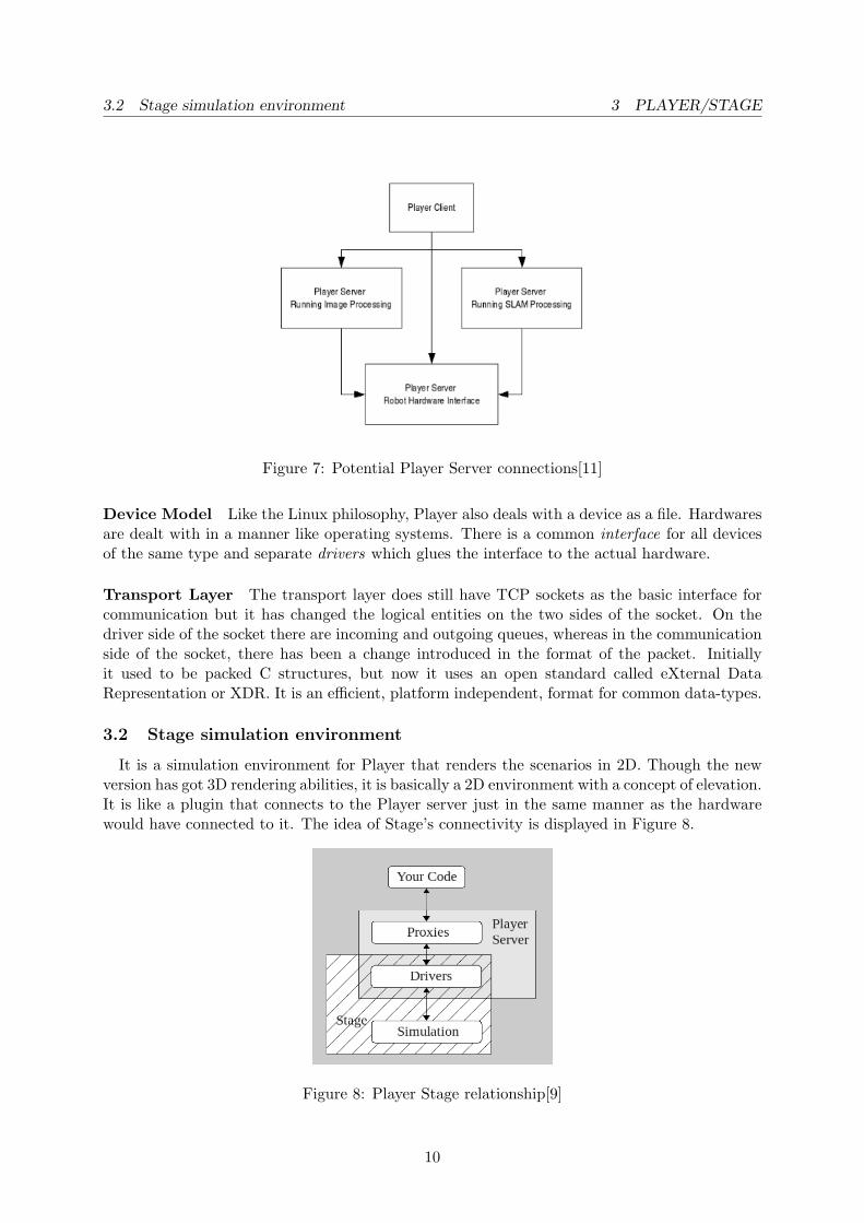
3.2 Stage simulation environment 3 PLAYER/STAGE
Figure 7: Potential Player Server connections[11]
Device Model Like the Linux philosophy, Player also deals with a device as a file. Hardwaresare dealt with in a manner like operating systems. There is a common interface for all devicesof the same type and separate drivers which glues the interface to the actual hardware.
Transport Layer The transport layer does still have TCP sockets as the basic interface forcommunication but it has changed the logical entities on the two sides of the socket. On thedriver side of the socket there are incoming and outgoing queues, whereas in the communicationside of the socket, there has been a change introduced in the format of the packet. Initiallyit used to be packed C structures, but now it uses an open standard called eXternal DataRepresentation or XDR. It is an efficient, platform independent, format for common data-types.
3.2 Stage simulation environment
It is a simulation environment for Player that renders the scenarios in 2D. Though the newversion has got 3D rendering abilities, it is basically a 2D environment with a concept of elevation.It is like a plugin that connects to the Player server just in the same manner as the hardwarewould have connected to it. The idea of Stage’s connectivity is displayed in Figure 8.
Figure 8: Player Stage relationship[9]
10

3.3 Working 3 PLAYER/STAGE
In Figure 8, we see that the Stage simulator tricks the Player Server by substituting thehardware and cloning the drivers. Stage was designed with the multi-robot systems (MRS) inmind. Hence speed was more important than accuracy. Another motivation for designing Stagewas to substitute hardware and reduce cost. It also gave a chance to experiment with new typesof sensors which are not yet available as readymade hardware in the market. It also helps instudying multi robot behaviours, which would have been otherwise very costly.
Some of the major features of Stage [3] are:-
• Optimal fidelity : It looks more into performance than accuracy.
• Linear Scaling with population: The algorithms are such designed that they do not dependon the number of the robots.
• Configurable device models: The sensor models are modelled with a lot of flexibility andto conform as much closely as possible to the actual nature of the hardware. They arefully configurable as much as the original hardware provides.
• Abstraction from Client code: The sensors are available through the Player interface, hencethe client code cannot distinguish from the real sensors or the simulated sensors.
Figure 9: Player/Stage in action: An obstacle avoiding robot of Appendix B
3.3 Working
The basic working mechanism of the Player/Stage platform is explained in Figure 8. For itsproper functioning, there is a need to understand three file types:-
• .world file: It tells Player/Stage what things are available to put in the world. We describeour robot, any items which populate the world and the layout of the world.
11

3.4 Pros, Cons and buzz 4 URBI
• .inc file: They are also of the same format as that of the .world files, but they are generallyused to define one entity only. These files are then included in the final .world files whichrepresents the simulation.
• .cfg file: This is the most important file as this specifies which driver to use for whichdevice and the location of the drivers.
Another concept that is needed to be understood, is that of a model. Everything is representedas model in the simulation. The map, objects, obstacles, robots and all are models. Every modelhas a name and a host of parameters which defines its physical properties like colour, draggable,grippable, and others. There are a lot of built-in models representing the basic needs of roboticslike sensors and actuators. Then comes the external code. As mentioned before, the user cancode his/her algorithm in various languages like C, C++, Java, and Python according to theuser’s wish.
3.4 Pros, Cons and buzz
The logical layout of the architecture and a maintenance of close configurability with itshardware counterparts, gives a close feeling of using hardware rather than software. The easeof use and the simplicity alongwith the usage of our favourite programming language makes ita very popular platform amidst academicians and hobbyists. But the absence of robustness,missing constraints of real-time demands, inability to be ported cleanly on Windows platformand the difficulty of installation causes a hindrance in its popularity. Whatever, the platform ofPlayer/Stage is the de facto standard in the domain of robotics in the open source community.
4 URBI
This is another proprietary Robot Programming Language. URBI stands for Universal Real-time Behaviour Interface and is developed by a company named Gostai, dedicated to ArtificialIntelligence applied to Robotics, based in France. It is basically a new language all together andthe company defends their stand as to why a new language is needed for present day roboticsapplications. Their mission is to provide the users with the best universal robotic platform. Theproduct has been developed by leading Universities in the field of Artificial Intelligence since2003.
4.1 Design philosophy
URBI’s observation is that we are entering the robotic age and still there is incompatibility interms of software for the available hardware of robotics. It is much like the problem of havingdifferent PC architectures faced by the computer industry in its nascent days. Hence it is theireffort to bridge the gap by providing a common platform for robotic applications. The product[2] has been designed with the following principles in mind:-
Flexibility The platform should work with any robot, operating system or programmingenvironment.
Modularity It follows an architecture in which components are modular in nature, hencebuilt and maintained separately. They are all executed together in the platform.
12

4.2 URBI Technology 4 URBI
Powerful Abstractions Robotics is a very complex domain and at the same time there existsa lot of redundancy which needs to be abstracted out to increase efficiency and elegance.
Simplicity Another principle which URBI strongly follows is that none of the above thingsshould be tough to understand or use. Things should be so easy such that hobbyists or kids canhave a quick kickstart.
4.2 URBI Technology
URBI is quite an innovation in the programming world as it is not just a programminglanguage (urbiScript) but also has a component architecture (UObject) and also several graphicalprogramming tools (urbiStudio). Its integration of control over parallelism in the syntax of thelanguage is a very noble approach. All this along with a familiar C++ like syntax, makes it avery attractive platform.
Lets have a look at the two pillars of their technology:-
• URBI Script : This forms the heart of the technology. It brings totally new featuresand simplicity in the issues of parallelism and event-based programming. It is also fullyinterfaced with other languages like C++, Java, Matlab, Python, and Ruby. It doesn’tallow full control of flow to these traditional languages, but just allows it to issue URBIcommands using the traditional programming constructs. So basically, it is the URBIserver which keeps control over the flow of execution and executes the commands as theykeep coming from the user code. Parallelism and events are directly controlled and alsovisible in the syntax of the urbiScript. Some real-time aspects are also controlled directlyby the urbiScript. For instance, if a task has to be spread over a specific time span, thenit can be directly specified in the code, just beside where the task is initiated. Figures 10and 11 exhibit a few of these features.
Figure 10: Event-Handling and Parallelism in urbiScript[2]
In Figure 10, we see both the features of event-handling and parallelism being present.The event-handling keyword ‘whenever’ declares this piece of code to invoked when theevent ‘ball.visible’ (i.e. ball is within camera’s view field) occurs. The ‘headPan’variable represents the servo motor which controls the movement of the robot’s headabout the vertical axis. Similarly, the ‘headTilt’ variable represents the servo motorwhich controls the robot’s head movement about the horizontal axis. The parallelismfeature is represented in the code by the ‘&’ operator. By using it between the two codes,the two commands are executed parallely and we will be able to see that the head of therobot moves along the diagonal towards the ball. Had it been executed serially, then the
13

4.3 Pros, Cons and buzz 4 URBI
robot would have first aligned its head along the x-axis of the ball then aligned itself alongthe y-axis of the ball.
Figure 11: Advanced features in urbiScript[2]
In Figure 11, we see three different pieces of code. In the first code, we see someconstraints being attached to the codes. The first line mentions that the ‘neck’ motor’svalue will be set to ‘10’ over a ‘timespan’ of ‘450ms’. The second line specifies that the‘leg’ motor’s value is set to ‘-45’ degrees and the transition occurs at the speed of ‘7.5’units. The third line says that ‘tail’ motor’s value will be ‘14’ and the transition willoccur over a sin wave like motion of amplitude ‘45’ units, and the transition will take placeover a period of 4s.The second part of Figure 11, handles an anomalous behaviour of parallelism, where thesame variable may be demanded to be modified and set two different values. Such cases arehandled by the ‘blend’ property which defines what to do, when such a situation comes.For example, in this figure, it is mentioned that it will ‘add’ thus the value of ‘x’ becomes‘4’ as the effect is added.The third part of Figure 11, displays some features of code tagging. A part of code, whichare inside the curly braces, is tagged as ‘mytag’. That part of code can be referred to fromany part of the program by the tag, and commands like stop (to stop the code), freeze(to pause the code), and unfreeze (to start the frozen code) can be executed upon them.
• UObject Architecture: The UObjects are very similar to C++ objects. Infact C++ objectscan be very easily converted to UObjects. There was a need to have a different objectarchitecture as they wanted the objects to conform to their overall principle of simplicityand have abstractions over network complexities. The principle can be extended to anydistributed object architecture and it bridges the gap between other component architec-tures like CORBA. In UObject architecture it is also possible to add new methods atruntime to a live object.
4.3 Pros, Cons and buzz
The main advantage of the product is the ease with which parallelism and event handling canbe done. Some time constraints can also be very easily controlled by the user. The disadvantagewould include the pain of having to learn a new language. Even if it does have the facility tointegrate with other languages, but it doesn’t give the full control to those languages, rather
14

5 OROCOS
they have to generate URBI commands to the URBI server. It is quite a popular product forthe hardware that it supports, and its popularity may increase from May, 2010 onwards as it isgoing to be open source from then onwards.
5 OROCOS
OROCOS stands for Open RObot COntrol Software. Their aim is to build a generic modularframework for robot and machine control. They just provide libraries for building but does notstrictly provide a platform. They give stress on accuracy rather than on computation.
Figure 12: OROCOS libraries[1]
5.1 Design philosophy
Their design philosophy [1] is centered around four libraries, namely:-
• RealTime Toolkit (RTT): This library ensures realtime constraints.
• Orocos Components Library (OCL): This library is used to design components which rep-resents real life entities like sensors and actuators. It uses the KDL.
• Kinematics and Dynamics Library (KDL): It is an application independent frameworkfor modelling and computation of kinematic chains, such as robots, biomechanical humanmodels, computer-animated figures, machine tools, etc.
• Bayesian filtering library (BFL): It is a library which uses statistical models to inducenoise into the models, which otherwise assumes a perfect world.
As seen in Figure 13, to build the base of an application, the RTT, BFL and KDL librariesare used. Then for the middle layer OCL is used, above which applications are developed andthen used by the final user.
5.2 Pros, Cons and buzz
It is the only platform that takes deep care of realtime issues. Unfortunately, it is not aplatform as a whole, hence most of the functionalities of networking, distribution of load, andhardware abstraction is left to the users. Yet, for those who want accurate results, and a perfectsimulation, this is the best library to look out for.
15

6 COMPARATIVE STUDY
Figure 13: OROCOS application development[1]
6 Comparative Study
Lets present a comparative study [10] of the four main products, in Table 1, which have beendiscussed above. Thus we can see that each product has its own advantages, disadvantages and
MSRDS Player/Stage URBI OROCOSOpen Source No Yes from May’10 YesWindows Yes Emulation Yes NoLinux No Yes Yes YesNature Platform Platform Platform LibraryDistributed Yes Partially Yes NoIn-built Arm Control No No No YesSimulation Yes Yes Yes NoReusability Yes No Yes YesReal-Time No No No Yes
Table 1: Comparative Study of Robot Programming Languages
specialities. In MSRDS, the loosely coupled nature of the DSS library, the distributed nature andefficiency of the CCR library and high quality of simulation gives it an edge. The simplicity andthe facility to use our favourite programming language makes Player/Stage a popular platform.The ease of programming in URBI, as many complexities of real life demands are abstracted out,makes it a very desirable platform. The parallelism handling feature of URBI makes it standapart from the others. The intricacies and accuracy of the OROCOS library is a challengingtask to build from scratch and it serves the purpose of applications which demand perfection.Having highlighted the dominating features of the above products, we would now like to moveonto (Section 7) the description of a desirable robotic platform which has the best features ofall the products mentioned above as well as some features totally missing from the above ones.
16

7 GENERAL REQUIREMENTS OF A PLATFORM
7 General Requirements of a Platform
After having studied some of the most popular robotic platforms available and having useda few of them, we would like to factor out all the important features of these products and listthe requirements of a complete robot programming platform. They are:-
• Abstraction and Uniformity : The foremost requirement of a platform is to provide unifor-mity of commands and syntax to control robots and lay down a complete abstraction overthe hardware differences.
• Scalability and Distributed Nature: With the era of distributed computing coming ahead,it is of utmost importance to provide distributed behaviour in the platform or to ensurethat it conforms to some standard which would help it to run on a distributed layer.The issue of scalability can be in general solved by providing a distributed nature but atthe same time it needs to be ensured that the scalability should result in linearly scaledperformance with increase in size of population.
• Modularity and Re-usability : Another very important issue is that of modularity. Sincethe real world components are modular by nature, and the hardware components arealso generally produced by different vendors, the platform should also deal with themseparately. This would help in isolating the errors and would also ease out development asthe developers would be only concentrating on a module and deal with it independentlyof the platform. This would also increase re-usability, as a component developed once canbe used perpetually.
• Parallelism and Synchronisation: In robotic applications, it is often required to do twoor more tasks in parallel, at the same time not conflicting with each other. Thus paral-lelism and synchronisation should not only be available but also should be well abstractedsuch that the user does not have to think about the coding complexities of threads andsemaphores but should just be concerned with the top level logic of dealing with them.
• Real-Time Constraints: Since robotic applications are all real world applications, handlingof real time constraints should be always expected from the platform.
• Error Handling and Debugging : One of the most important issues related to any formof software is the facility to debug it. Having a loosely coupled system distributed overa network, makes the job of debugging tougher. Having a simulation environment doesease the pain of debugging a lot but debugging in the simulation itself can be quite achallenging task.
• In built support for fundamental robotic activities: Fundamental robotic activities likeimage processing, robotic arm control and such other facilities should be readily availablesuch that the user can concentrate on the algorithm or artificial intelligence component ofthe system and not waste much time with the subtleties of the coding and handling wellestablished fields.
• Simplicity : Above all, the features provided should be all very simple to learn and use andshould not be very complex by itself.
17

8 CONCLUSION
8 Conclusion
Thus we have had a study of some interesting products in the world of robotic programming.We have also had a taste of development using two of them. The pros and cons of various otherproducts in the market have been studied and presented in a manner that brings out the needsof the present situation. Finally, a list of the general requirements of a robot programmingplatform has been suggested, which if implemented can meet all the varying demands of roboticdevelopment with ease.
18

REFERENCES REFERENCES
References
[1] Orocos website. Website. http://www.orocos.org, visited in 2010.
[2] Urbi/gostai website. Website. http://www.gostai.com, visited in 2010.
[3] Richard T. Vaughan Brian P. Gerkey and Andrew Howard. The Player/Stage Project: Toolsfor Multi-Robot and Distributed Sensor Systems. Proceedings of the 11th InternationalConference on Advanced Robotics (ICAR 2003), pages 317-323, Coimbra, Portugal, June2003.
[4] Microsoft Corporation. Ccr documentation. Website. http://msdn.microsoft.com/en-us/library/bb648752.aspx, visited in 2010.
[5] Microsoft Corporation. Dss documentation. Website. http://msdn.microsoft.com/en-us/library/bb483056.aspx, visited in 2010.
[6] Microsoft Corporation. Microsoft Robotics Developer Studio product Documentation.
[7] Microsoft Corporation. Video tutorials on simulation. Website. http://msdn.microsoft.com/en-us/robotics/bb383569.aspx, visited in 2010.
[8] Microsoft Corporation. Vpl documentation. Website. http://msdn.microsoft.com/en-us/library/bb483088.aspx, visited in 2010.
[9] Jennifer Owen. How to use player/stage. Website, 2009. http://playerstage.sourceforge.net/doc/playerstage_instructions_2.0.pdf.
[10] Michael Somby. A review of robotics software platforms. www.linuxfordevices.com, 2008.
[11] Bruce A. MacDonald Toby H.J. Collett and Brian P. Gerkey. Player 2.0: Toward a PracticalRobot Programming Framework. Proceedings of the Australasian Conference on Roboticsand Automation (ACRA 2005), Sydney, Australia, December 2005.
19

A MSRDS EXAMPLE
Appendices
A MSRDS Example
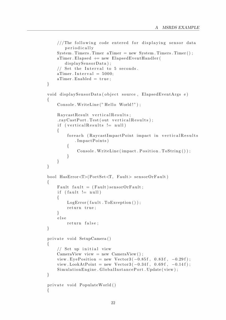
Here is a code whose screenshot is given in Figure 1.
us ing System ;us ing System . C o l l e c t i o n s . Generic ;us ing System . ComponentModel ;us ing Micro so f t . Ccr . Core ;us ing Micro so f t . Dss . Core . At t r ibute s ;us ing Micro so f t . Dss . ServiceModel . Dssp ;us ing Micro so f t . Dss . ServiceModel . DsspServiceBase ;us ing W3C. Soap ;us ing submgr = Microso f t . Dss . S e r v i c e s . Subscr ipt ionManager ;us ing engine = Microso f t . Robot ics . S imulat ion . Engine . Proxy ;
us ing Micro so f t . Robot ics . S imulat ion . Engine ;us ing Micro so f t . Robot ics . S imulat ion . Phys ics ;us ing Micro so f t . Robot ics . PhysicalModel ;
us ing dr iv e = Microso f t . Robot ics . S e r v i c e s . S imulat ion . Drive . Proxy ;
us ing l r f = Microso f t . Robot ics . S e r v i c e s . S imulat ion . Sensors .LaserRangeFinder . Proxy ;
us ing s i c k l r f = Microso f t . Robot ics . S e r v i c e s . Sensors . SickLRF . Proxy ;
// Fol lowing are used f o r a c c e s s i n g t imer to c r e a t e timeout to c a l l afunc t i on to d i s p l a y senso r data
us ing System . Linq ;us ing System . Text ;us ing System . Timers ;
namespace LineFol lowerTria lEnv1{
[ Contract ( Contract . I d e n t i f i e r ) ][ DisplayName (” LineFol lowerTria lEnv1 ”) ][ De sc r ip t i on (” LineFol lowerTria lEnv1 s e r v i c e ( no d e s c r i p t i o n
provided ) ”) ]c l a s s L ineFo l lowerTr ia lEnv1Serv i ce : DsspServiceBase{
/// <summary>/// S e r v i c e s t a t e/// </summary>[ S e r v i c e S t a t e ]L ineFol lowerTr ia lEnv1State s t a t e = new
LineFol lowerTr ia lEnv1State ( ) ;
20

A MSRDS EXAMPLE
/// <summary>/// Main s e r v i c e port/// </summary>[ S e rv i c ePor t (”/ LineFol lowerTria lEnv1 ” , A l lowMult ip l e Ins tances
= true ) ]L ineFol lowerTr ia lEnv1Operat ions mainPort = new
LineFol lowerTr ia lEnv1Operat ions ( ) ;
[ Subscr ipt ionManagerPartner ]submgr . Subscr ipt ionManagerPort submgrPort = new submgr .
Subscr ipt ionManagerPort ( ) ;
/// <summary>/// Simulat ionEngine partner/// </summary>[ Partner (” Simulat ionEngine ” , Contract = engine . Contract .
I d e n t i f i e r , Creat ionPo l i cy = PartnerCreat ionPo l i cy .UseExist ingOrCreate ) ]
eng ine . Simulat ionEnginePort s imulat ionEng inePort = newengine . Simulat ionEnginePort ( ) ;
Port<RaycastResult> rayCastPort = new Port<RaycastResult >() ;
/// <summary>/// S e r v i c e con s t ruc to r/// </summary>pub l i c L ineFo l lowerTr ia lEnv1Serv i ce ( DsspServ iceCreat ionPort
c r ea t i onPor t ): base ( c r ea t i onPor t )
{}
/// <summary>/// S e r v i c e s t a r t/// </summary>protec ted o v e r r i d e void Star t ( ){
//// Add s e r v i c e s p e c i f i c i n i t i a l i z a t i o n here//
base . S ta r t ( ) ;// Orient sim camera view pointSetupCamera ( ) ;// Add o b j e c t s ( e n t i t i e s ) in our s imulated worldPopulateWorld ( ) ;
21
A MSRDS EXAMPLE
///The f o l l o w i n g code entered f o r d i s p l a y i n g senso r datap e r i o d i c a l l y
System . Timers . Timer aTimer = new System . Timers . Timer ( ) ;aTimer . Elapsed += new ElapsedEventHandler (
d i sp laySensorData ) ;// Set the I n t e r v a l to 5 seconds .aTimer . I n t e r v a l = 5000 ;aTimer . Enabled = true ;
}
void disp laySensorData ( ob j e c t source , ElapsedEventArgs e ){
Console . WriteLine (” He l lo World ! ” ) ;
RaycastResult v e r t i c a l R e s u l t s ;rayCastPort . Test ( out v e r t i c a l R e s u l t s ) ;
i f ( v e r t i c a l R e s u l t s != n u l l ){
f o r each ( RaycastImpactPoint impact in v e r t i c a l R e s u l t s. ImpactPoints )
{Console . WriteLine ( impact . Po s i t i on . ToString ( ) ) ;
}}
}
bool HasError<T>(PortSet<T, Fault> sensorOrFault ){
Fault f a u l t = ( Fault ) sensorOrFault ;i f ( f a u l t != n u l l ){
LogError ( f a u l t . ToException ( ) ) ;r e turn true ;
}e l s e
re turn f a l s e ;}
p r i v a t e void SetupCamera ( ){
// Set up i n i t i a l viewCameraView view = new CameraView ( ) ;view . EyePos it ion = new Vector3 (−0.85 f , 0 .83 f , −0.29 f ) ;view . LookAtPoint = new Vector3 (−0.34 f , 0 .69 f , −0.14 f ) ;S imulat ionEngine . Globa l InstancePort . Update ( view ) ;
}
p r i v a t e void PopulateWorld ( ){
22

A MSRDS EXAMPLE
AddSky ( ) ;AddGround ( ) ;AddTable (new Vector3 (1 , 0 . 5 f , −2) ) ;AddLine (new Vector3 (1 , 0 , 1) ) ;AddLine2 (new Vector3 (2 , 0 , 1) ) ;AddPioneer3DXRobot (new Vector3 (1 , 0 . 1 f , 0) ) ;
}
#reg ion CODECLIP 03−3void AddSky ( ){
// Add a sky us ing a s t a t i c t ex ture . We w i l l use the skytex ture
// to do per p i x e l l i g h t i n g on each s imu la t i on v i s u a le n t i t y
SkyDomeEntity sky = new SkyDomeEntity (” skydome . dds ” , ”s k y d i f f . dds ”) ;
S imulat ionEngine . Globa l InstancePort . I n s e r t ( sky ) ;
// Add a d i r e c t i o n a l l i g h t to s imulate the sun .L ightSourceEnt i ty sun = new LightSourceEnt i ty ( ) ;sun . State .Name = ”Sun ” ;sun . Type = LightSourceEntityType . D i r e c t i o n a l ;sun . Color = new Vector4 ( 0 . 8 f , 0 . 8 f , 0 . 8 f , 1) ;sun . D i r e c t i on = new Vector3 ( 0 . 5 f , −.75 f , 0 . 5 f ) ;S imulat ionEngine . Globa l InstancePort . I n s e r t ( sun ) ;
}#endreg ion
#reg i on CODECLIP 03−4void AddGround ( ){
// c r e a t e a l a r g e h o r i z o n t a l plane , at zero e l e v a t i o n .He ightF ie ldEnt i ty ground = new HeightF ie ldEnt i ty (
” s imple ground ” , // name” b lackSur face . dds ” , // t ex ture imagenew M at e r i a l P r op e r t i e s (” ground ” ,
0 . 2 f , // r e s t i t u t i o n0 .5 f , // dynamic f r i c t i o n0 .5 f ) // s t a t i c f r i c t i o n
) ;Simulat ionEngine . Globa l InstancePort . I n s e r t ( ground ) ;
}#endreg ion
void AddTable ( Vector3 p o s i t i o n ){
// c r e a t e an in s t ance o f our custom e n t i t yTableEntity e n t i t y = new TableEntity ( p o s i t i o n ) ;
23

A MSRDS EXAMPLE
// Name the e n t i t ye n t i t y . State .Name = ” t a b l e : ” + Guid . NewGuid ( ) . ToString ( ) ;
// I n s e r t e n t i t y in s imu la t i on .Simulat ionEngine . Globa l InstancePort . I n s e r t ( e n t i t y ) ;
}
#reg ion CODECLIP 03−5void AddLine ( Vector3 p o s i t i o n ){
Vector3 dimensions =new Vector3 ( 0 . 5 f , 0 .01 f , 0 .05 f ) ; // meters
// c r e a t e s imple movable ent i ty , with a s i n g l e shapeS ing leShapeEnt i ty box = new Sing leShapeEnt i ty (
new BoxShape (new BoxShapePropert ies (10 , // mass in k i lograms .new Pose ( ) , // r e l a t i v e posedimensions ) ) , // dimensions
p o s i t i o n ) ;
box . State . MassDensity . Mass = 0 ;box . State . MassDensity . Density = 0 ;
// Name the e n t i t y . Al l e n t i t i e s must have unique namesbox . State .Name = ”box ” ;
// I n s e r t e n t i t y in s imu la t i on .Simulat ionEngine . Globa l InstancePort . I n s e r t ( box ) ;
}void AddLine2 ( Vector3 p o s i t i o n ){
Vector3 dimensions =new Vector3 ( 0 . 5 f , 0 .01 f , 0 .05 f ) ; // meters
// c r e a t e s imple movable ent i ty , with a s i n g l e shapeS ing leShapeEnt i ty box = new Sing leShapeEnt i ty (
new BoxShape (new BoxShapePropert ies (10 , // mass in k i lograms .new Pose (new Vector3 (0 , 0 , 0) , new Quaternion ( 0 . 0
f , 0 .383 f , 0 . 0 f , 0 .9239 f ) ) , // r e l a t i v e posedimensions ) ) , // dimensions
p o s i t i o n ) ;
box . State . MassDensity . Mass = 0 ;box . State . MassDensity . Density = 0 ;
24

A MSRDS EXAMPLE
// Name the e n t i t y . Al l e n t i t i e s must have unique namesbox . State .Name = ”box2 ” ;
// I n s e r t e n t i t y in s imu la t i on .Simulat ionEngine . Globa l InstancePort . I n s e r t ( box ) ;
}#endreg ion
void AddPioneer3DXRobot ( Vector3 p o s i t i o n ){
Pioneer3DX robotBaseEntity = CreateMotorBase ( r e f p o s i t i o n) ;
// Create Laser e n t i t y and s t a r t s imulated l a s e r s e r v i c eLaserRangeFinderEntity l a s e r = CreateLaserRangeFinder ( ) ;// i n s e r t l a s e r as c h i l d to motor baserobotBaseEntity . I n s e r t E n t i t y ( l a s e r ) ;
// F i n a l l y i n s e r t the motor base and i t s c h i l d s enso r// to the s imu la t i onSimulat ionEngine . Globa l InstancePort . I n s e r t (
robotBaseEntity ) ;}
p r i v a t e LaserRangeFinderEntity CreateLaserRangeFinder ( ){
// Create a Laser Range Finder Entity .// Place i t 10cm above base CenterofMass .LaserRangeFinderEntity l a s e r = new LaserRangeFinderEntity
(new Pose (new Vector3 (0 , 0 .10 f , 0) ) ) ;
l a s e r . State .Name = ”P3DXLaserRangeFinder ” ;l a s e r . LaserBox . State . D i f f u s eCo lo r = new Vector4 ( 0 . 2 5 f ,
0 .25 f , 0 . 8 f , 1 . 0 f ) ;
// Create LaserRangeFinder s imu la t i on s e r v i c e and s p e c i f y// which e n t i t y i t t a l k s tol r f . Contract . Crea teSe rv i c e (
ConstructorPort ,Mic roso f t . Robot ics . S imulat ion . Partners .
CreateEnt i tyPartner (” http :// l o c a l h o s t /” + l a s e r . State .Name) ) ;
l a s e r . Reg i s t e r ( rayCastPort ) ;
r e turn l a s e r ;
25

A MSRDS EXAMPLE
}
p r i v a t e Pioneer3DX CreateMotorBase ( r e f Vector3 p o s i t i o n ){
// use supp l i ed e n t i t y that c r e a t e s a motor base// with 2 a c t i v e wheels and one c a s t e rPioneer3DX robotBaseEntity = new Pioneer3DX ( p o s i t i o n ) ;
// s p e c i f y mesh .robotBaseEntity . State . Assets . Mesh = ” Pioneer3dx . bos ” ;// s p e c i f y c o l o r i f no mesh i s s p e c i f i e d .robotBaseEntity . ChassisShape . State . D i f f u s eCo lo r = new
Vector4 ( 0 . 8 f , 0 .25 f , 0 .25 f , 1 . 0 f ) ;
// the name below must match mani f e s trobotBaseEntity . State .Name = ”P3DXMotorBase ” ;
#reg i on CODECLIP 04−1// Star t s imulated arcos motor s e r v i c ed r iv e . Contract . Crea teSe rv i c e ( ConstructorPort ,
Mic roso f t . Robot ics . S imulat ion . Partners .CreateEnt i tyPartner (” http :// l o c a l h o s t /” + robotBaseEntity . State .Name)
) ;#endreg ionreturn robotBaseEnt ity ;
}
/// <summary>/// Handles Subscr ibe messages/// </summary>/// <param name=”s u bs c r i b e”>the s ub s c r i b e request </param>[ Serv i ceHandler ]pub l i c void Subscr ibeHandler ( Subscr ibe s u b s c r i b e ){
Subscr ibeHe lper ( submgrPort , su b s c r i b e . Body , su b s c r i b e .ResponsePort ) ;
}}
}
[ DataContract ]pub l i c c l a s s TableEntity : MultiShapeEntity{
/// <summary>/// Defau l t con s t ruc to r ./// </summary>pub l i c TableEntity ( ) { }
26

A MSRDS EXAMPLE
/// <summary>/// Custom const ructor , programmatica l ly b u i l d s phys i c s p r i m i t i v e
shapes to d e s c r i b e/// a p a r t i c u l a r t a b l e ./// </summary>/// <param name=”p o s i t i o n”></param>pub l i c TableEntity ( Vector3 p o s i t i o n ){
State . Pose . Po s i t i on = p o s i t i o n ;State . Assets . Mesh = ” t a b l e 0 1 . obj ” ;f l o a t tab l eHe ight = 0.65 f ;f l o a t tableWidth = 1.05 f ;f l o a t tableDepth = 0 .7 f ;f l o a t tab leThinkness = 0.03 f ;f l o a t l egTh icknes s = 0 .03 f ;f l o a t l e g O f f s e t = 0 .05 f ;
// add a shape f o r the t a b l e s u r f a c eBoxShape tableTop = new BoxShape (
new BoxShapePropert ies (30 ,new Pose (new Vector3 (0 , tableHeight , 0) ) ,new Vector3 ( tableWidth , tableThinkness , tableDepth ) )
) ;
// add a shape f o r the l e f t l e gBoxShape tab l eLe f tLeg = new BoxShape (
new BoxShapePropert ies (10 , // mass in kgnew Pose (
new Vector3(−tableWidth / 2 + l e g O f f s e t , tab l eHe ight/ 2 , 0) ) ,
new Vector3 ( legThickness , tab l eHe ight + tableThinkness ,tableDepth ) )
) ;
BoxShape tableRightLeg = new BoxShape (new BoxShapePropert ies (10 , // mass in kgnew Pose (
new Vector3 ( tableWidth / 2 − l e g O f f s e t , tab l eHe ight /2 , 0) ) ,
new Vector3 ( legThickness , tab l eHe ight + tableThinkness ,tableDepth ) )
) ;
BoxShapes = new List<BoxShape>() ;BoxShapes . Add( tableTop ) ;BoxShapes . Add( tab l eLe f tLeg ) ;BoxShapes . Add( tableRightLeg ) ;
}
27

B PLAYER/STAGE EXAMPLE
pub l i c o v e r r i d e void Update ( FrameUpdate update ){
base . Update ( update ) ;}
}
B Player/Stage Example
Let us now go through an example which will help in understanding the features better:-
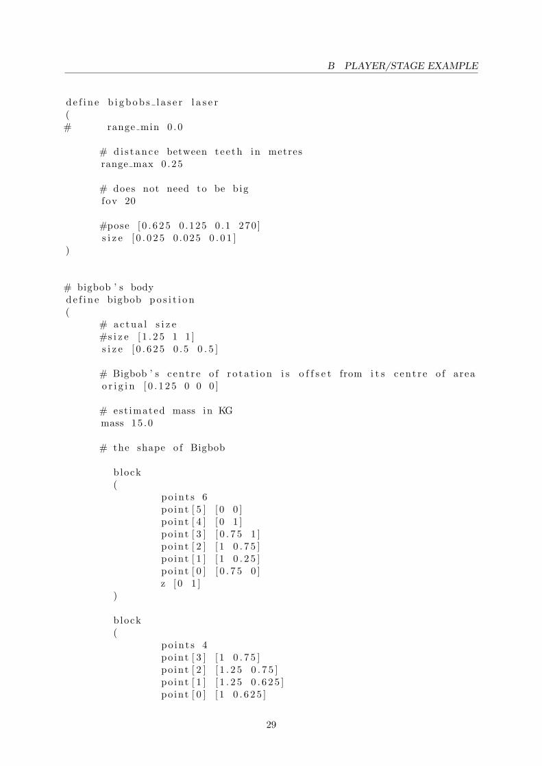
The robot’s .inc file This file [9](named bigbob.inc) contains the description of the robotas a two dimentional object identified by points of a polygon. The sensor’s nature, positions,count and other physical parameters are also specified here. Here is the file:-
#Bigbob ’ s sonarsd e f i n e b igbobs sonar s ranger(
# number o f sonarsscount 4
# d e f i n e the pose o f each transducer [ xpos ypos heading ]spose [ 0 ] [ 0 .75 0 .1875 0 ] #f r l e f t toothspose [ 1 ] [ 0 .75 −0.1875 0 ] #f r r i g h t toothspose [ 2 ] [ 0 .25 0 .5 30 ] # l e f t cornerspose [ 3 ] [ 0 .25 −0.5 −30] # r i g h t corner
# d e f i n e the f i e l d o f view o f each transducer#[ range min range max v iew ang le ]sview [ 0 . 3 2 . 0 10 ]
# d e f i n e the s i z e o f each t ransducer# [ x s i z e y s i z e ] in meterss s i z e [ 0 . 0 1 0 . 0 5 ]
)
# bigbob ’ s b l o b f i n d e rd e f i n e b igbobs eye s b l o b f i n d e r(
# number o f c o l o u r s to look f o rc o l o r s c o u n t 2
# which c o l o u r s to look f o rc o l o r s [ ” orange ” ”DarkBlue ” ]
# camera parametersimage [160 120 ] #r e s o l u t i o n
)
# bigbob ’ s l a s e r
28
B PLAYER/STAGE EXAMPLE
d e f i n e b i g b o b s l a s e r l a s e r(# range min 0 .0
# d i s t anc e between tee th in metresrange max 0 .25
# does not need to be bigfov 20
#pose [ 0 . 6 2 5 0 .125 0 .1 270 ]s i z e [ 0 . 0 2 5 0 .025 0 . 0 1 ]
)
# bigbob ’ s bodyd e f i n e bigbob p o s i t i o n(
# actua l s i z e#s i z e [ 1 . 2 5 1 1 ]s i z e [ 0 . 6 2 5 0 .5 0 . 5 ]
# Bigbob ’ s c en t r e o f r o t a t i o n i s o f f s e t from i t s c en t r e o f areao r i g i n [ 0 . 1 2 5 0 0 0 ]
# est imated mass in KGmass 15 .0
# the shape o f Bigbob
block(
po in t s 6po int [ 5 ] [ 0 0 ]po int [ 4 ] [ 0 1 ]po int [ 3 ] [ 0 . 7 5 1 ]po int [ 2 ] [ 1 0 . 7 5 ]po int [ 1 ] [ 1 0 . 2 5 ]po int [ 0 ] [ 0 . 7 5 0 ]z [ 0 1 ]
)
b lock(
po in t s 4po int [ 3 ] [ 1 0 . 7 5 ]po int [ 2 ] [ 1 . 2 5 0 . 7 5 ]po int [ 1 ] [ 1 . 2 5 0 . 6 2 5 ]po int [ 0 ] [ 1 0 . 6 2 5 ]
29

B PLAYER/STAGE EXAMPLE
z [ 0 0 . 5 ])
b lock(
po in t s 4po int [ 3 ] [ 1 0 . 3 7 5 ]po int [ 2 ] [ 1 . 2 5 0 . 3 7 5 ]po int [ 1 ] [ 1 . 2 5 0 . 2 5 ]po int [ 0 ] [ 1 0 . 2 5 ]z [ 0 0 . 5 ]
)
# d i f f e r e n t i a l s t e e r i n g modeld r i v e ” d i f f ”
# s e n s o r s attached to bigbobb igbobs sonar s ( )b igbobs eye s ( )b i g b o b s l a s e r ( )
o b s t a c l e r e t u r n 1 # Can h i t th ing s .l a s e r r e t u r n 1 # r e f l e c t s l a s e r beamsrange r r e tu rn 1 # r e f l e c t s sonar beamsb lob r e tu rn 1 # Seen by b l o b f i n d e r s
)
The map.inc file specifies the map, on which the robot will move. It is as follows:-
d e f i n e map model(
# sombre , s e n s i b l e , a r t i s t i cc o l o r ” black ”# most maps w i l l need a bounding boxboundary 1gu i no s e 1g u i g r i d 1#range r r e tu rn 1 # r e f l e c t s sonar beamsgui move 0g u i o u t l i n e 0f i d u c i a l r e t u r n 0g r i p p e r r e t u r n 0l a s e r r e t u r n 1
)
The empty.world [9] contains all the information of the environment. It also includes the.inc files defined above. It is as follows:-
i n c lude ”map . inc ”
30

B PLAYER/STAGE EXAMPLE
i n c lude ” bigbob . inc ”#inc lude ” s i c k . inc ”
# s i z e o f the whole s imu la t i ons i z e [ 15 15 ]
# c o n f i g u r e the GUI windowwindow(
s i z e [ 650 .0 650 .0 ] # in p i x e l s# 650/15 rounded up a b i ts c a l e 43 # in p i x e l s /meter#show data 1
)# load an environment bitmapmap(
bitmap ”bitmaps/ cave . png”pose [ 0 0 0 0 ]s i z e [ 15 15 1 . 6 0 ]
)
bigbob(
name ”bob1”pose [−5 −6 0 0 ]c o l o r ” red ”
)
The empty.cfg file [9] specifies the drivers which the Player Server will use. It is as follows:-
d r i v e r(
name ” s tage ”p lug in ” s t agep lug in ”prov ide s [ ” s imu la t i on : 0 ” ]# load the named f i l e i n to the s imu la torw o r l d f i l e ”empty . world ”
)
d r i v e r(
name ” s tage ”prov ide s [ ” 6 6 6 5 : po s i t i on2d :0” ”6665 : b l o b f i n d e r : 0” ”6665 : l a s e r
: 0” ”6665 : sonar : 0 ” ]model ”bob1”
)
The Player Server needs to be invoked after these four files have been defined. To do so, use thefollowing command:-
p laye r empty . c f g
31

B PLAYER/STAGE EXAMPLE
This will not only initiate the Player server but also the Stage simulation window. The robotcan be located in it in red colour.
The user code (code.cpp) [9] which controls the robot is as follows:-
#inc lude <s t d i o . h>#inc lude <uni s td . h>#inc lude <time . h>#inc lude < l i b p l a y e r c++/p laye r c++.h>
us ing namespace PlayerCc ;us ing namespace std ;
void AvoidObstacles ( double ∗ forwardSpeed , double ∗ turnSpeed ,SonarProxy &sp )
{// w i l l avoid o b s t a c l e s c l o s e r than 40cmdouble avo idDistance = . 4 ;// w i l l turn away at 10 degree s / seci n t avoidTurnSpeed = 10 ;// l e f t corner i s sonar no . 2// r i g h t corner i s sonar no . 3i f ( sp [ 2 ] < avo idDistance ){
∗ forwardSpeed = 0 ;// turn r i g h t∗ turnSpeed = (−1)∗avoidTurnSpeed ;re turn ;
}e l s e i f ( sp [ 3 ] < avo idDistance ){
∗ forwardSpeed = 0 ;// turn l e f t∗ turnSpeed = avoidTurnSpeed ;re turn ;
}e l s e i f ( ( sp [ 0 ] < 2∗ avo idDistance ) | | ( sp [ 1 ] < 2∗ avo idDistance ) ){
// back o f f a l i t t l e b i t∗ forwardSpeed = −0.3;i f ( sp [0] < sp [ 1 ] ) // I f l e f t s enso r i s c l o s e r then r i g h t s enso r
∗ turnSpeed = −(rand ( ) %70+20) ; //Take a r i g h t turnrandomly ranging between 20 and 90 degree s
e l s e∗ turnSpeed = rand ( ) %70+20; //Take a random l e f t turn
return ;}re turn ; //do nothing
}
32

B PLAYER/STAGE EXAMPLE
i n t main ( i n t argc , char ∗argv [ ] ){
// Enabling Prox ie sP laye rC l i en t robot (” l o c a l h o s t ”) ;Posit ion2dProxy p2dProxy(&robot , 0 ) ;SonarProxy sonarProxy(&robot , 0 ) ;Blobf inderProxy blobProxy(&robot , 0 ) ;LaserProxy lase rProxy(&robot , 0 ) ;
// enable motorsp2dProxy . SetMotorEnable (1 ) ;// r eque s t geometr i e sp2dProxy . RequestGeom ( ) ;sonarProxy . RequestGeom ( ) ;l a se rProxy . RequestGeom ( ) ;// b l o b f i n d e r d o e s n t have geometry
//some c o n t r o l codedouble forwardSpeed , turnSpeed ;srand ( time (NULL) ) ;whi l e ( t rue ){
// read from the p r ox i e srobot . Read ( ) ;cout<<”Distance :”<<sonarProxy [0]<<” ”<<sonarProxy [1]<<” ”<<
sonarProxy [2]<<” ”<<sonarProxy [3]<< endl ;
forwardSpeed = . 7 ;turnSpeed = 0 ;
// c a l l a func t i on to avoid o b s t a c l e sAvoidObstacles (&forwardSpeed , &turnSpeed , sonarProxy ) ;
// s e t motorsp2dProxy . SetSpeed ( forwardSpeed , dtor ( turnSpeed ) ) ;s l e e p (1 ) ; // wait f o r one second
}re turn 0 ;
}
This code should be compiled using:
g++ −o code ‘ pkg−c o n f i g −−c f l a g s p laye r c++‘ code . cpp ‘ pkg−c o n f i g −−l i b s p l aye r c++‘
Then the code should be executed using: ‘./code’ command. This should connect to the PlayerServer and the robot should start moving according to this algorithm.
33