surveillance data exchange part 18 : … · surveillance data exchange part 18 : category 019 ......
TRANSCRIPT
EUROPEAN ORGANISATION FOR THE SAFETY OF AIR NAVIGATION
EUROCONTROL
EUROPEAN AIR TRAFFIC MANAGEMENT
EUROCONTROL STANDARD DOCUMENT
FOR
SURVEILLANCE DATA EXCHANGE
Part 18 : Category 019
Multilateration System Status Messages
SUR.ET1.ST05.2000-STD-18-02
Edition : 1.1 Edition Date : March 2007 Status : Released Issue Class : General Public
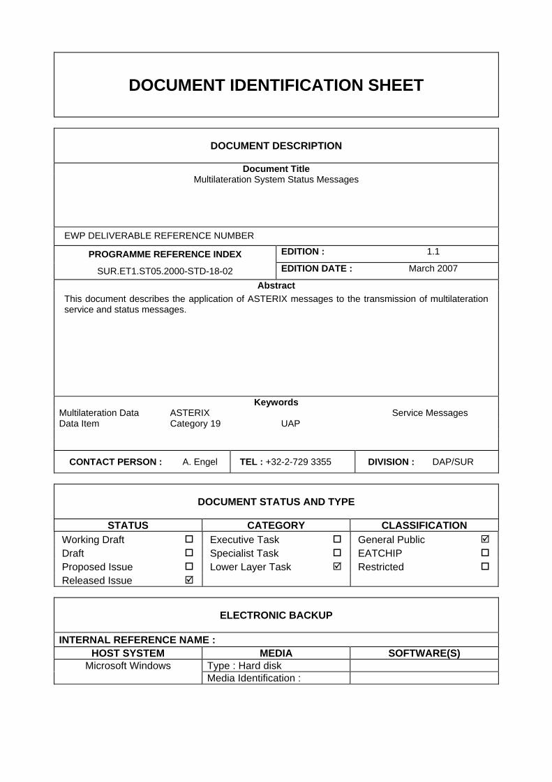
DOCUMENT IDENTIFICATION SHEET
DOCUMENT DESCRIPTION
Document Title Multilateration System Status Messages
EWP DELIVERABLE REFERENCE NUMBER
PROGRAMME REFERENCE INDEX EDITION : 1.1
SUR.ET1.ST05.2000-STD-18-02 EDITION DATE : March 2007
Abstract This document describes the application of ASTERIX messages to the transmission of multilateration service and status messages.
Keywords Multilateration Data ASTERIX Service Messages Data Item Category 19 UAP
CONTACT PERSON : A. Engel TEL : +32-2-729 3355 DIVISION : DAP/SUR
DOCUMENT STATUS AND TYPE
STATUS CATEGORY CLASSIFICATION Working Draft Executive Task General Public Draft Specialist Task EATCHIP Proposed Issue Lower Layer Task Restricted Released Issue
ELECTRONIC BACKUP
INTERNAL REFERENCE NAME : HOST SYSTEM MEDIA SOFTWARE(S)
Microsoft Windows Type : Hard disk Media Identification :
Multilateration System Status Messages SUR.ET1.ST05.2000-STD-18-02
DOCUMENT APPROVAL
The following table identifies all management authorities who have successively approved the present issue of this document.
AUTHORITY NAME AND SIGNATURE DATE
ASTERIX
Manager
D. Doukas
SUR Domain
Manager
J. Berends
SURT
Chairman
M. Rees
EATM/DAP
Director
G. Kerkhofs
Edition : 1.1 Released Issue Page iii
SUR.ET1.ST05.2000-STD-18-02 Multilateration System Status Messages
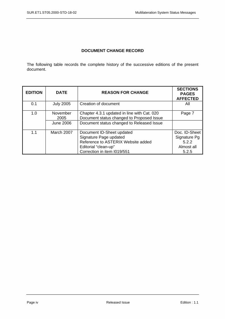
DOCUMENT CHANGE RECORD
The following table records the complete history of the successive editions of the present document.
EDITION DATE REASON FOR CHANGE SECTIONS
PAGES AFFECTED
0.1 July 2005 Creation of document All
November 2005
Chapter 4.3.1 updated in line with Cat. 020 Document status changed to Proposed Issue
Page 7 1.0
June 2006 Document status changed to Released Issue
1.1 March 2007 Document ID-Sheet updated Signature Page updated Reference to ASTERIX Website added Editorial “clean-up” Correction in item I019/551
Doc. ID-SheetSignature Pg
5.2.2 Almost all
5.2.5
Page iv Released Issue Edition : 1.1
Multilateration System Status Messages SUR.ET1.ST05.2000-STD-18-02
TABLE OF CONTENTS
DOCUMENT IDENTIFICATION SHEET.................................................................................. ii
DOCUMENT APPROVAL....................................................................................................... iii
DOCUMENT CHANGE RECORD .......................................................................................... iv
TABLE OF CONTENTS...........................................................................................................v
EXECUTIVE SUMMARY .........................................................................................................1
1. INTRODUCTION...............................................................................................2 1.1 Scope ...............................................................................................................2
2. REFERENCES..................................................................................................3 2.1 General.............................................................................................................3 2.2 Reference Documents ....................................................................................3
3. DEFINITIONS, ACRONYMS AND ABBREVIATIONS.....................................5 3.1 Definitions........................................................................................................5 3.2 Acronyms and Abbreviations ........................................................................6
4. GENERAL PRINCIPLES ..................................................................................7 4.1 General.............................................................................................................7 4.2 Time Management...........................................................................................7
4.2.1 Definition .................................................................................................................... 7
4.2.2 Requirements for Time Stamping .............................................................................. 7
4.3 Projection Systems and Geographical Coordinates ...................................7
4.3.1 Coordinates Expressed in the Local 2D Coordinate Reference System (Cartesian Representation): .............................................................................................................. 7
4.3.2 Coordinates Expressed in WGS-84 Format (Geographical Coordinates):................. 8
4.4 Unused Bits in Data Items..............................................................................8 4.5 Definitions and Addressing Concepts ..........................................................8
4.5.1 Sensor........................................................................................................................ 8
Edition : 1.1 Released Issue Page v
SUR.ET1.ST05.2000-STD-18-02 Multilateration System Status Messages
4.5.2 System ....................................................................................................................... 8
4.5.3 Addressing Concepts: Assigning SAC/SIC Codes..................................................... 8
4.6 Target Reports.................................................................................................8 4.7 Service Messages ...........................................................................................8 4.8 User Application Profile and Data Blocks ....................................................9 4.9 Composition of Messages..............................................................................9
5. LAYOUT OF MESSAGES ..............................................................................10 5.1 Standard Data Items .....................................................................................10 5.2 Description of Standard Data Items ............................................................11
5.2.1 Data Item I019/000, Message Type ......................................................................... 11
5.2.2 Data Item I019/010, Data Source Identifier.............................................................. 13
5.2.3 Data Item I019/140, Time of Day ............................................................................. 14
5.2.4 Data Item I019/550, System Status ......................................................................... 15
5.2.5 Data Item I019/551, Tracking Processor Detailed Status ........................................ 16
5.2.6 Data Item I019/552, Remote Sensor Detailed Status .............................................. 17
5.2.7 Data Item I019/553, Reference Transponder Detailed Status ................................. 18
5.2.8 Data Item I019/600, Position of the MLT System Reference Point.......................... 19
5.2.9 Data Item I019/610, Height of the MLT System Reference Point ............................ 20
5.2.10 Data Item I019/620, WGS-84 Undulation................................................................. 20
5.3 Standard User Application Profile...............................................................21
Page vi Released Issue Edition : 1.1
Multilateration System Status Messages SUR.ET1.ST05.2000-STD-18-02
EXECUTIVE SUMMARY
This document describes the general concepts and the message layout for the application of ASTERIX category 19 for the transmission of service and status messages related to multilateration systems.
Edition : 1.1 Released Issue Page 1
SUR.ET1.ST05.2000-STD-18-02 Multilateration System Status Messages
1. INTRODUCTION
1.1 Scope
1.1.1 This document describes the message structure for the transmission of multilateration service and system status messages.
1.1.2 A complex of MLT (transmitter)/receivers and a central processing system is seen as a mono sensor.
Page 2 Released Issue Edition : 1.1
Multilateration System Status Messages SUR.ET1.ST05.2000-STD-18-02
2. REFERENCES
2.1 General
The following Documents and Standards contain provisions which, through references in this text, constitute provisions of this Eurocontrol Document.
At the time of publication of this Eurocontrol Document, the editions indicated for the referenced documents and standards were valid.
Any revision of the referenced ICAO Documents shall be immediately taken into account to revise this Eurocontrol Document.
Revisions of the other referenced documents shall not form part of the provisions of this Eurocontrol Document until they are formally reviewed and incorporated into this Eurocontrol Document.
In case of a conflict between the requirements of this Eurocontrol Document and the contents of the other referenced documents, this Eurocontrol Document shall take precedence.
2.2 Reference Documents
1. Eurocontrol Standard 000-1-92. Directives for the Uniform Drafting and Presentation of Eurocontrol Standard Documents. 1992.
2. Eurocontrol Standard SUR.ET1.ST05.2000-STD-01-01. All Purpose Structured Eurocontrol Surveillance Information Exchange - ASTERIX. Edition 1.28, Working Draft, December 2001.
Edition : 1.1 Released Issue Page 3
SUR.ET1.ST05.2000-STD-18-02 Multilateration System Status Messages
This page is intentionally left blank
Page 4 Released Issue Edition : 1.1
Multilateration System Status Messages SUR.ET1.ST05.2000-STD-18-02
3. DEFINITIONS, ACRONYMS AND ABBREVIATIONS
3.1 Definitions
For the purposes of this Eurocontrol Document, the following definitions shall apply:
3.1.1 Catalogue of Data Items:
List of all possible Data Items of each Data Category describing the Data Items by their reference, structure, size and units (where applicable).
Unit of information seen by the application as a discrete entity by its contents. A Data Block contains one or more Record(s) containing data of the same category.
3.1.2 Data Block:
Classification of the data in order to allow for, inter alia, an easy identification.
3.1.3 Data Category:
Physical implementation for the purpose of communication of a Data Item. It is associated with a unique Field Reference Number and is the smallest unit of transmitted information.
3.1.4 Data Field:
The smallest unit of information in each Data Category. 3.1.5 Data Item:
A piece of information (e.g. the position of a target) derived from the sensor information and transmitted without any smoothing.
3.1.6 Measured Item:
A collection of transmitted Data Fields of the same category preceded by a Field Specification field, signalling the presence/absence of the various Data Fields
3.1.7 Record:
The mechanism for assigning Data Items to Data Fields, and containing all necessary information which needs to be standardised for the successful encoding and decoding of the messages.
3.1.8 User Application Profile:
Edition : 1.1 Released Issue Page 5
SUR.ET1.ST05.2000-STD-18-02 Multilateration System Status Messages
3.2 Acronyms and Abbreviations
For the purposes of this Eurocontrol Document the following shall apply:
° Degree (angle) ASTERIX All Purpose STructured Eurocontrol suRveillance Information EXchange CAT Data Category DOP Dilution Of Precision EATM European Air Traffic Management FL Flight Level, unit of altitude (expressed in 100's of feet) FRN Field Reference Number FSPEC Field Specification FX Field Extension Indicator ICAO International Civil Aviation Organization kt knot = NM/hour, unit of speed LEN Length Indicator LSB Least Significant Bit MLT Multilateration NM Nautical Mile, unit of distance (1852 metres) PSR Primary Surveillance Radar RDE-FG Radar Data Exchange Focus Group RE Reserved Expansion Indicator REP Field Repetition Indicator s second, unit of time SAC System Area Code SIC System Identification Code SMR Surface Movement Radar SMS Surface Movement System SP Special Purpose Indicator SPI Special Position Identification SSR Secondary Surveillance Radar SURT Surveillance Team (EATM) UAP User Application Profile (see Definitions ) UTC Coordinated Universal Time WAM Wide Area Multilateration WGS-84 World Geodetic System 84
Page 6 Released Issue Edition : 1.1
Multilateration System Status Messages SUR.ET1.ST05.2000-STD-18-02
4. GENERAL PRINCIPLES
4.1 General
For the transmission of MLT data the following two types of messages have been defined: • target reports,
• service and status messages.
This document describes the service and status messages only. The target report messages are described in part 14, category 020 of the ASTERIX documents.
4.2 Time Management
4.2.1 Definition The time stamp shall be consistent with the reported target position.
4.2.2 Requirements for Time Stamping The timestamping shall comply with ICAO Annex 5.
4.3 Projection Systems and Geographical Coordinates
Two different types of Coordinate reference systems are supported.
4.3.1 Coordinates Expressed in the Local 2D Coordinate Reference System (Cartesian Representation):
The exported position can be expressed in a 2D Cartesian Coordinate system, which is a plane tangential to the WGS-84 Ellipsoid at the location of the reference point as defined in item I019/600. The origin of the Cartesian Coordinate system coincides with the published system origin. The Y-axis points to the geographical north at that position. The X-axis is perpendicular to the Y-axis and points to the east. The X, Y Coordinates are calculated using either the measured height or an assumed target height and apply a suitable projection technique for the final 3D to 2D conversion (e.g. a stereographical projection)..
All tracker derived information elements, shall be a consistent set of values, expressed in the same Coordinate reference system (state vector components and the corresponding elements of the track quality vector).
Edition : 1.1 Released Issue Page 7
SUR.ET1.ST05.2000-STD-18-02 Multilateration System Status Messages
4.3.2 Coordinates Expressed in WGS-84 Format (Geographical Coordinates):
The exported position can be expressed in a 2D or 3D WGS-84 format. In case of 3D representation the item 019/610 (Height of MLT System Reference Point) has to be used in combination with item 019/600 (Position of the MLT System Reference Point).
4.4 Unused Bits in Data Items.
Decoders of ASTERIX data shall never assume and rely on specific settings of spare or unused bits. However in order to improve the readability of binary dumps of ASTERIX records, it is recommended to set all spare bits to zero.
4.5 Definitions and Addressing Concepts
In order to address sources in an unambiguous way, a simple abstract model for concepts like sensors or systems has been designed.
4.5.1 Sensor In the framework of Category 019 a multilateration sensor is:
• a complex of MLT (transmitter)/receivers and a central processing system
4.5.2 System In the framework of category 019 a System is a Sensor.
4.5.3 Addressing Concepts: Assigning SAC/SIC Codes By convention a dedicated and unambiguous SAC/SIC code shall be assigned to every System.
4.6 Target Reports
Target reports include reports from a multilateration system. They are described in part 14 as ASTERIX category 020.
4.7 Service Messages
Three types of service messages have been identified:
• Start of Update Cycle (for a system using a cyclic update mechanism, these messages shall be used to signal the start of a new data renewal cycle),
• Periodic Status Messages (these messages should be used by systems to indicate their status periodically),
• Event-triggered Status Messages (these messages should be used by systems to indicate their status in case of events).
Page 8 Released Issue Edition : 1.1
Multilateration System Status Messages SUR.ET1.ST05.2000-STD-18-02
4.8 User Application Profile and Data Blocks
4.8.1 A single User Application Profile (UAP) is defined and shall be used for both target reports and service messages.
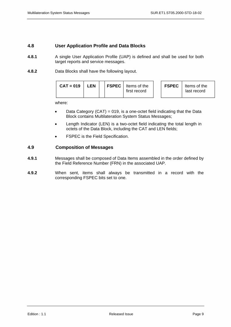
4.8.2 Data Blocks shall have the following layout.
CAT = 019 LEN FSPEC Items of the first record
FSPEC Items of the last record
where:
• Data Category (CAT) = 019, is a one-octet field indicating that the Data Block contains Multilateration System Status Messages;
• Length Indicator (LEN) is a two-octet field indicating the total length in octets of the Data Block, including the CAT and LEN fields;
• FSPEC is the Field Specification.
4.9 Composition of Messages
4.9.1 Messages shall be composed of Data Items assembled in the order defined by the Field Reference Number (FRN) in the associated UAP.
4.9.2 When sent, items shall always be transmitted in a record with the corresponding FSPEC bits set to one.
Edition : 1.1 Released Issue Page 9
SUR.ET1.ST05.2000-STD-18-02 Multilateration System Status Messages
5. LAYOUT OF MESSAGES
5.1 Standard Data Items
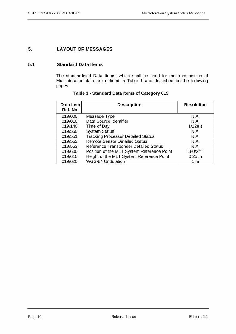
The standardised Data Items, which shall be used for the transmission of Multilateration data are defined in Table 1 and described on the following pages.
Table 1 - Standard Data Items of Category 019
Data Item Ref. No.
Description Resolution
I019/000 Message Type N.A. I019/010 Data Source Identifier N.A. I019/140 Time of Day 1/128 s I019/550 System Status N.A. I019/551 Tracking Processor Detailed Status N.A. I019/552 Remote Sensor Detailed Status N.A. I019/553 Reference Transponder Detailed Status N.A.
180/230° I019/600 Position of the MLT System Reference Point I019/610 Height of the MLT System Reference Point 0.25 m I019/620 WGS-84 Undulation 1 m
Page 10 Released Issue Edition : 1.1
Multilateration System Status Messages SUR.ET1.ST05.2000-STD-18-02
5.2 Description of Standard Data Items
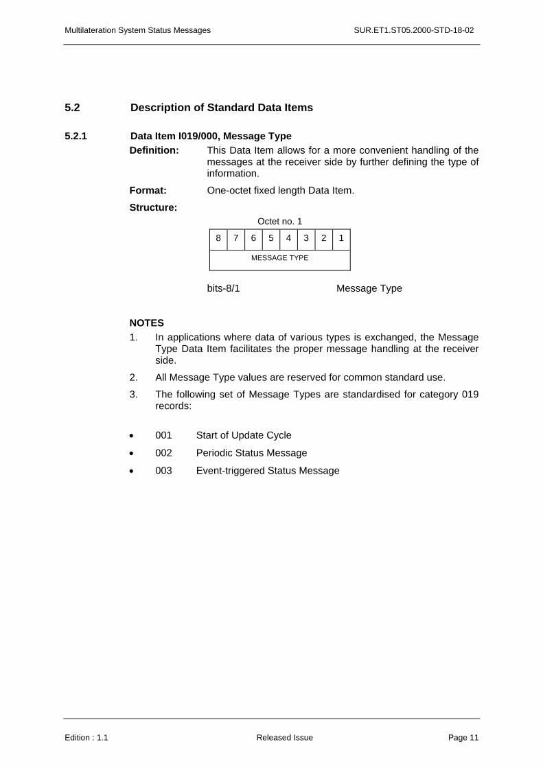
5.2.1 Data Item I019/000, Message Type Definition: This Data Item allows for a more convenient handling of the
messages at the receiver side by further defining the type of information.
Format: One-octet fixed length Data Item.
Structure: Octet no. 1
8 7 6 5 4 3 2 1
MESSAGE TYPE
bits-8/1 Message Type NOTES
1. In applications where data of various types is exchanged, the Message Type Data Item facilitates the proper message handling at the receiver side.
2. All Message Type values are reserved for common standard use.
3. The following set of Message Types are standardised for category 019 records:
• 001 Start of Update Cycle
• 002 Periodic Status Message
• 003 Event-triggered Status Message
Edition : 1.1 Released Issue Page 11
SUR.ET1.ST05.2000-STD-18-02 Multilateration System Status Messages
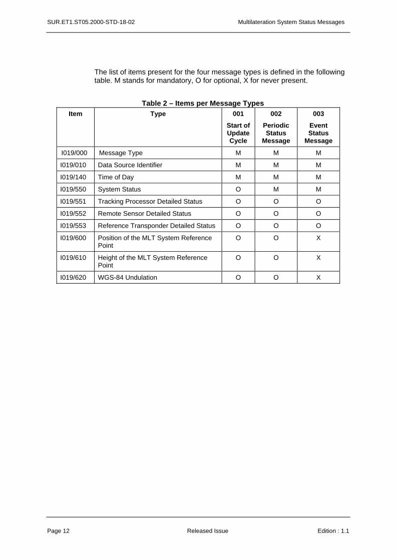
The list of items present for the four message types is defined in the following table. M stands for mandatory, O for optional, X for never present.
Table 2 – Items per Message Types
Item Type 001
Start of Update Cycle
002
Periodic Status
Message
003
Event Status
Message
I019/000 Message Type M M M
I019/010 Data Source Identifier M M M
I019/140 Time of Day M M M
I019/550 System Status O M M
I019/551 Tracking Processor Detailed Status O O O
I019/552 Remote Sensor Detailed Status O O O
I019/553 Reference Transponder Detailed Status O O O
I019/600 Position of the MLT System Reference Point
O O X
I019/610 Height of the MLT System Reference Point
O O X
I019/620 WGS-84 Undulation O O X
Page 12 Released Issue Edition : 1.1
Multilateration System Status Messages SUR.ET1.ST05.2000-STD-18-02
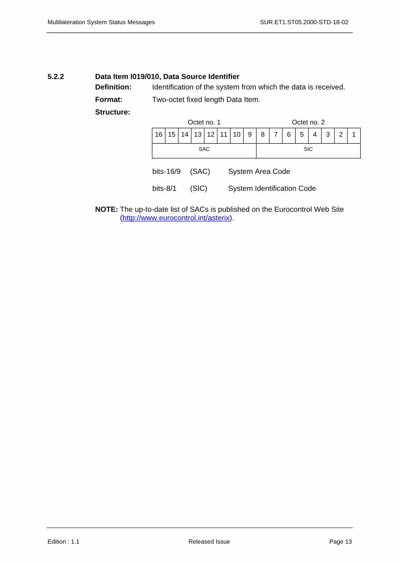
5.2.2 Data Item I019/010, Data Source Identifier Definition: Identification of the system from which the data is received.
Format: Two-octet fixed length Data Item.
Structure: Octet no. 1 Octet no. 2
16 15 14 13 12 11 10 9 8 7 6 5 4 3 2 1
SAC SIC
bits-16/9 (SAC) System Area Code bits-8/1 (SIC) System Identification Code
NOTE: The up-to-date list of SACs is published on the Eurocontrol Web Site (http://www.eurocontrol.int/asterix).
Edition : 1.1 Released Issue Page 13
SUR.ET1.ST05.2000-STD-18-02 Multilateration System Status Messages
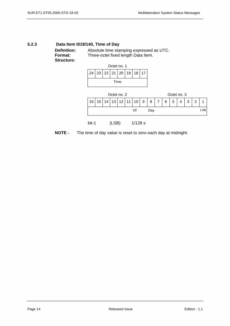
5.2.3 Data Item I019/140, Time of Day Definition: Absolute time stamping expressed as UTC. Format: Three-octet fixed length Data Item. Structure:
Octet no. 1
24 23 22 21 20 19 18 17
Time
Octet no. 2 Octet no. 3
16 15 14 13 12 11 10 9 8 7 6 5 4 3 2 1
Of Day LSB
bit-1 (LSB) 1/128 s
NOTE - The time of day value is reset to zero each day at midnight.
Page 14 Released Issue Edition : 1.1
Multilateration System Status Messages SUR.ET1.ST05.2000-STD-18-02
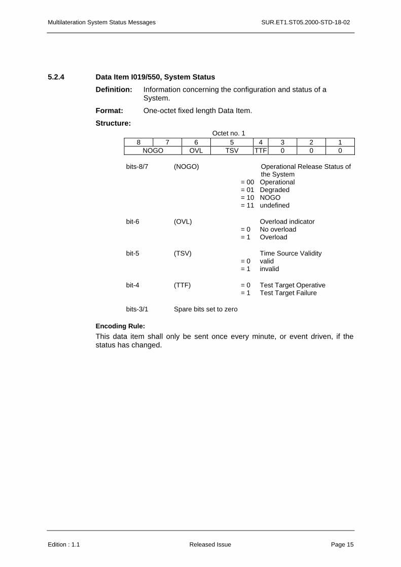
5.2.4 Data Item I019/550, System Status Definition: Information concerning the configuration and status of a
System.
Format: One-octet fixed length Data Item.
Structure: Octet no. 1
8 7 6 5 4 3 2 1 NOGO OVL TSV TTF 0 0 0
bits-8/7 (NOGO) Operational Release Status of
the System = 00 Operational = 01 Degraded = 10
= 11 NOGO undefined
bit-6 (OVL) Overload indicator = 0 No overload = 1 Overload
bit-5 (TSV) Time Source Validity = 0 valid = 1 invalid
bit-4 (TTF) = 0 Test Target Operative = 1 Test Target Failure
bits-3/1 Spare bits set to zero
Encoding Rule: This data item shall only be sent once every minute, or event driven, if the status has changed.
Edition : 1.1 Released Issue Page 15
SUR.ET1.ST05.2000-STD-18-02 Multilateration System Status Messages
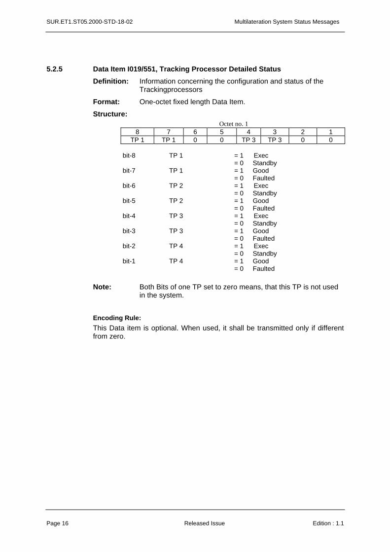
5.2.5 Data Item I019/551, Tracking Processor Detailed Status Definition: Information concerning the configuration and status of the
Trackingprocessors
Format: One-octet fixed length Data Item.
Structure: Octet no. 1
8 7 6 5 4 3 2 1 TP 1 TP 1 0 0 TP 3 TP 3 0 0
bit-8 TP 1 = 1 Exec = 0 Standby bit-7 TP 1 = 1 Good = 0 Faulted bit-6 TP 2 = 1 Exec = 0 Standby bit-5 TP 2 = 1 Good = 0 Faulted bit-4 TP 3 = 1 Exec = 0 Standby bit-3 TP 3 = 1 Good = 0 Faulted bit-2 TP 4 = 1 Exec = 0 Standby bit-1 TP 4 = 1 Good = 0 Faulted
Note: Both Bits of one TP set to zero means, that this TP is not used
in the system.
Encoding Rule: This Data item is optional. When used, it shall be transmitted only if different from zero.
Page 16 Released Issue Edition : 1.1
Multilateration System Status Messages SUR.ET1.ST05.2000-STD-18-02
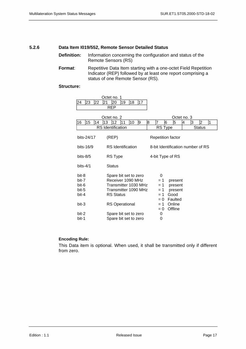
5.2.6 Data Item I019/552, Remote Sensor Detailed Status Definition: Information concerning the configuration and status of the
Remote Sensors (RS)
Format: Repetitive Data Item starting with a one-octet Field Repetition Indicator (REP) followed by at least one report comprising a status of one Remote Sensor (RS).
Structure:
Octet no. 1 24 23 22 21 20 19 18 17
REP
Octet no. 2 Octet no. 3 16 15 14 13 12 11 10 9 8 7 6 5 4 3 2 1
RS Identification RS Type Status
bits-24/17 (REP) Repetition factor bits-16/9 RS Identification 8-bit Identification number of RS bits-8/5 RS Type 4-bit Type of RS
bits-4/1 Status
bit-8 Spare bit set to zero 0 bit-7 Receiver 1090 MHz = 1 present bit-6 Transmitter 1030 MHz = 1 present bit-5 Transmitter 1090 MHz = 1 present bit-4 RS Status = 1 Good = 0 Faulted bit-3 RS Operational = 1 Online = 0 Offline bit-2 Spare bit set to zero 0 bit-1 Spare bit set to zero 0
Encoding Rule: This Data item is optional. When used, it shall be transmitted only if different from zero.
Edition : 1.1 Released Issue Page 17
SUR.ET1.ST05.2000-STD-18-02 Multilateration System Status Messages
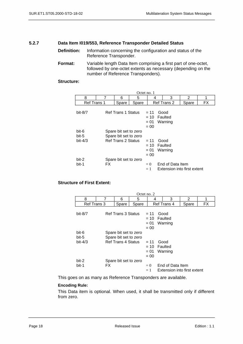
5.2.7 Data Item I019/553, Reference Transponder Detailed Status Definition: Information concerning the configuration and status of the
Reference Transponder.
Format: Variable length Data Item comprising a first part of one-octet, followed by one-octet extents as necessary (depending on the number of Reference Transponders).
Structure:
Octet no. 1 8 7 6 5 4 3 2 1 Ref Trans 1 Spare Spare Ref Trans 2 Spare FX
bit-8/7 Ref Trans 1 Status = 11 Good = 10 Faulted = 01 Warning = 00 bit-6 Spare bit set to zero bit-5 Spare bit set to zero bit-4/3 Ref Trans 2 Status = 11 Good = 10 Faulted = 01 Warning = 00 bit-2 Spare bit set to zero bit-1 FX = 0 End of Data Item = 1 Extension into first extent
Structure of First Extent:
Octet no. 2
8 7 6 5 4 3 2 1 Ref Trans 3 Spare Spare Ref Trans 4 Spare FX
bit-8/7 Ref Trans 3 Status = 11 Good = 10 Faulted = 01 Warning = 00 bit-6 Spare bit set to zero bit-5 Spare bit set to zero bit-4/3 Ref Trans 4 Status = 11 Good = 10 Faulted = 01 Warning = 00 bit-2 Spare bit set to zero bit-1 FX = 0 End of Data Item = 1 Extension into first extent
This goes on as many as Reference Transponders are available.
Encoding Rule: This Data item is optional. When used, it shall be transmitted only if different from zero.
Page 18 Released Issue Edition : 1.1
Multilateration System Status Messages SUR.ET1.ST05.2000-STD-18-02
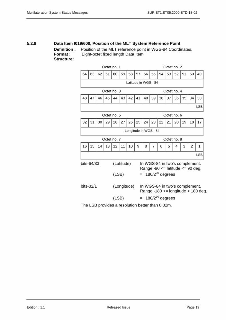
5.2.8 Data Item I019/600, Position of the MLT System Reference Point Definition : Position of the MLT reference point in WGS-84 Coordinates. Format : Eight-octet fixed length Data Item Structure:
Octet no. 1 Octet no. 2
64 63 62 61 60 59 58 57 56 55 54 53 52 51 50 49
Latitude in WGS - 84
Octet no. 3 Octet no. 4
48 47 46 45 44 43 42 41 40 39 38 37 36 35 34 33
LSB
Octet no. 5 Octet no. 6
32 31 30 29 28 27 26 25 24 23 22 21 20 19 18 17
Longitude in WGS - 84
Octet no. 7 Octet no. 8
16 15 14 13 12 11 10 9 8 7 6 5 4 3 2 1
LSB
bits-64/33 (Latitude) In WGS-84 in two’s complement. Range -90 <= latitude <= 90 deg. (LSB) = 180/230 degrees
bits-32/1 (Longitude) In WGS-84 in two’s complement. Range -180 <= longitude < 180 deg.
(LSB) = 180/230 degrees
The LSB provides a resolution better than 0.02m.
Edition : 1.1 Released Issue Page 19
SUR.ET1.ST05.2000-STD-18-02 Multilateration System Status Messages
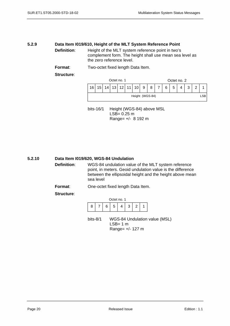
5.2.9 Data Item I019/610, Height of the MLT System Reference Point Definition: Height of the MLT system reference point in two’s
complement form. The height shall use mean sea level as the zero reference level.
Format: Two-octet fixed length Data Item.
Structure: Octet no. 1 Octet no. 2
16 15 14 13 12 11 10 9 8 7 6 5 4 3 2 1
Height (WGS-84) LSB
bits-16/1 Height (WGS-84) above MSL
LSB= 0.25 m Range= +/- 8 192 m
5.2.10 Data Item I019/620, WGS-84 Undulation Definition: WGS-84 undulation value of the MLT system reference
point, in meters. Geoid undulation value is the difference between the ellipsoidal height and the height above mean sea level
Format: One-octet fixed length Data Item.
Structure: Octet no. 1
8 7 6 5 4 3 2 1
bits-8/1 WGS-84 Undulation value (MSL)
LSB= 1 m Range= +/- 127 m
Page 20 Released Issue Edition : 1.1
Multilateration System Status Messages SUR.ET1.ST05.2000-STD-18-02
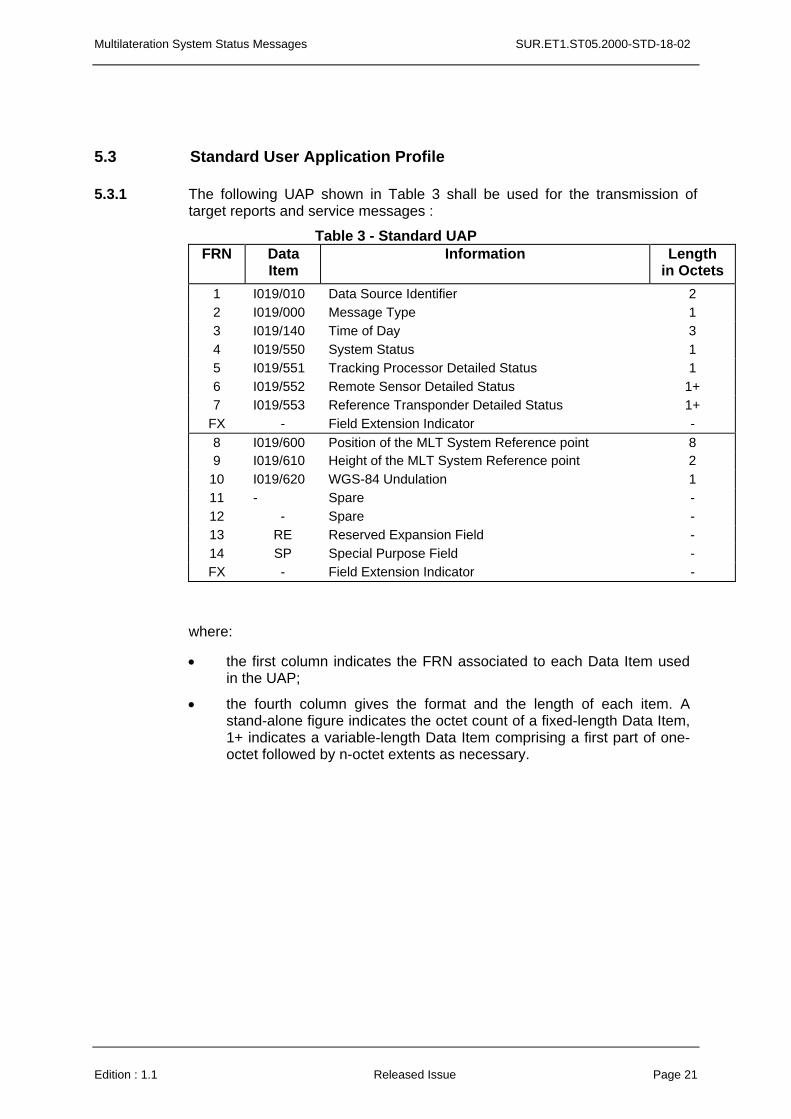
5.3 Standard User Application Profile
5.3.1 The following UAP shown in Table 3 shall be used for the transmission of target reports and service messages :
Table 3 - Standard UAP FRN Data
Item Information Length
in Octets 1 I019/010 Data Source Identifier 2 2 I019/000 Message Type 1 3 I019/140 Time of Day 3 4 I019/550 System Status 1 5 I019/551 Tracking Processor Detailed Status 1 6 I019/552 Remote Sensor Detailed Status 1+ 7 I019/553 Reference Transponder Detailed Status 1+
FX - Field Extension Indicator - 8 I019/600 Position of the MLT System Reference point 8 9 I019/610 Height of the MLT System Reference point 2
10 I019/620 WGS-84 Undulation 1 11 - Spare - 12 - Spare - 13 RE Reserved Expansion Field - 14 SP Special Purpose Field - FX - Field Extension Indicator -
where:
• the first column indicates the FRN associated to each Data Item used in the UAP;
• the fourth column gives the format and the length of each item. A stand-alone figure indicates the octet count of a fixed-length Data Item, 1+ indicates a variable-length Data Item comprising a first part of one-octet followed by n-octet extents as necessary.
Edition : 1.1 Released Issue Page 21