surgical manual echoplan pro a - sweden & martina
TRANSCRIPT

Surgical manual ECHOPLAN PRO A

Echoplan PRO A kitInformation 4
Clinical information about implant-retained prosthetic therapies 4Side and secondary effects 5General indication 6Guide sleeves 8
Premium One and Prama implants 9Implant mounters and connections 9Premium One implants 10Prama implants 11
Surgical instruments 12General indications 12Echoplan PRO A surgical kit 13Rotating instruments 16Fixing pins and drills 17From planning to implant insertion: stages in Echoplan guided surgery 18Surgical instruments used in the initial stage 19Intermediate and final drills 21Drills provided with the Echoplan PRO A kit 22Optional drills for 6.00 and 7.00 mm heights 24Optional drills for 18.00 mm height 24Bone taps 26Countersink drills 27Drivers for connecting screws 28Mounters 30Easy Insert - mounters 32Hand knob for removal of the GS-MOU-DG mounter 33GSMOUNT-TRAY-INT mounter organizer 34CRI5-KIT torque control ratchet 35Dynamometric key with TWL control lever 37
Surgical sequences 38Preparation of the implant site 38Surgical sequences – Premises 40Preliminary surgical sequences 41Surgical sequences – ø 4.15 mm sleeve 42Surgical sequences – ø 5.50 mm sleeve 44Surgical sequences – 18.00 mm height implants 46
Surgical procedures 48Insertion of the implant 48Cleaning, disinfection, sterilization and conservation of the kit and the surgical instruments 50
General information 55Composition of the materials 55

INFORMATION
4
Clinical indications for resorting toimplantoprosthetic therapies
When assessing the patient, in addition to his/her eligibility with regards to implant-prosthetic rehabilitation, it is usually necessary to consider the contraindications that apply to oral surgery procedures in general. These include:
• clotting disorders, anticoagulant therapy;• healing or bone regeneration disorders;• decompensated diabetes mellitus;• metabolic or systemic diseases that compromise tissue regeneration with a particular
influence on healing and bone regeneration;• alcohol abuse, smoking and use of drugs;• immunosuppressive therapy, such as: chemotherapy and radiotherapy;• infections and inflammations, such as periodontitis and gingivitis;• poor oral hygiene;• inadequate motivation;• occlusion and/or articulation disorders as well as an inadequate interocclusal space;• inadequate alveolar process.
It is contraindicated to fit implants and implant restorations in patients with poor general or oral health, those who are unable to monitor their general conditions properly or those who have had organ transplants. Psychologically unstable patients, alcohol or drug abusers, and poorly motivated or uncooperative patients should also be considered unsuitable for this kind of treatment. Patients with poor periodontal health should first be treated and allowed to recover. In the presence of a lack of bone substance or poor quality of the receiving bone, such as to compromise the stability of the implant, suitable guided tissue regeneration must be performed prior to implant treatment.
Contraindications also include: bruxism, allergy to titanium (extremely rare), acute or chronicinfectious diseases, sub-acute chronic maxillary osteitis, systemic diseases, endocrine disorders,diseases resulting in microvascular disorders, pregnancy, breastfeeding, previous exposure toradiation, haemophilia, neutropenia, steroid use, diabetes mellitus, kidney failure and fibrousdysplasia. The normal contraindications common to all oral surgery must also be observed. Surgery is not recommended for patients on anti-coagulant, anticonvulsant and immunosuppressant therapies, with active inflammatory-infective processes of the oral cavity, and patients with BUN and creatinine values outside the norm. Patients with cardiovascular disease, hypertension, thyroid or parathyroid diseases, malignant tumours found in the 5 years preceding the operation, or nodularswellings must also be rejected.
Chemotherapies reduce or eliminate the ability of osseointegration, therefore patientsundergoing these treatments must be carefully screened before being rehabilitated with oralimplantoprostheses. Numerous cases of bisphosphonate-associated periimplant osteonecrosis of the mandible have been reported in the literature. This problem particularly applies to patients treated intravenously.As a post-operative precaution, the patient must avoid any kind of strenuous physical activity.
INFORMATION
5
Side and secondary effects
Situations that may occur after surgical procedures include temporary local swelling, edema, hematoma, temporary sensitivity alterations, temporary masticatory limitations, post-surgical microhemorrhages in the following 12-24 hours. The patient may also experience pain, speech problems, gingivitis, loss of bone crest, permanent paresthesia, dysesthesia, local or systemic infections, exfoliation, hyperplasia, and oronasal and oroantral fistulas, perforation of the labial or lingual plate, perforation of the Schneidarian membrane, bone fractures, implant fractures, fractures of the overstructures, aesthetic problems, unnoticed perforation of the nasal sinus, nerve injuries, impairment of natural dentition. The following pathophysiological problems can increase the risks: cardiovascular failure, coronary disease, arrhythmia, pulmonary or chronic respiratory disease, gastrointestinal disease, hepatitis, inflammatory bowel disease, chronic kidney failure and disorders of the urinary system, endocrine disorders, diabetes, thyroid diseases, hematologic disorders, anaemia, leukaemia, coagulation problems, osteoporosis or musculoskeletal arthritis, stroke, neurological disorders, mental retardation, paralysis.
Before proceeding, it is important to perform a careful pre-operative analysis of the patient’s medical history to verify his or her suitability for the implant treatment. It is also recommended to collect and file all the clinical, radiological and radiographic records.
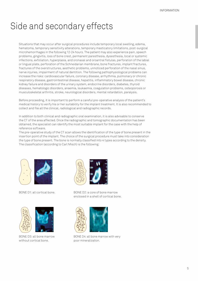
In addition to both clinical and radiographic oral examination, it is also advisable to conserve the CT of the area affected. Once the radiographic and tomographic documentation has been obtained, the specialist can identify the most suitable implant for the case with the help of reference software.The pre-operative study of the CT scan allows the identification of the type of bone present in theinsertion point of the implant. The choice of the surgical procedure must take into considerationthe type of bone present. The bone is normally classified into 4 types according to the density.The classification (according to Carl Misch) is the following:
BONE D1: all cortical bone. BONE D2: a core of bone marrow enclosed in a shell of cortical bone.
BONE D3: all bone marrow without cortical bone.
BONE D4: all bone marrow with very poor mineralization.
INFORMATION
6
General indication
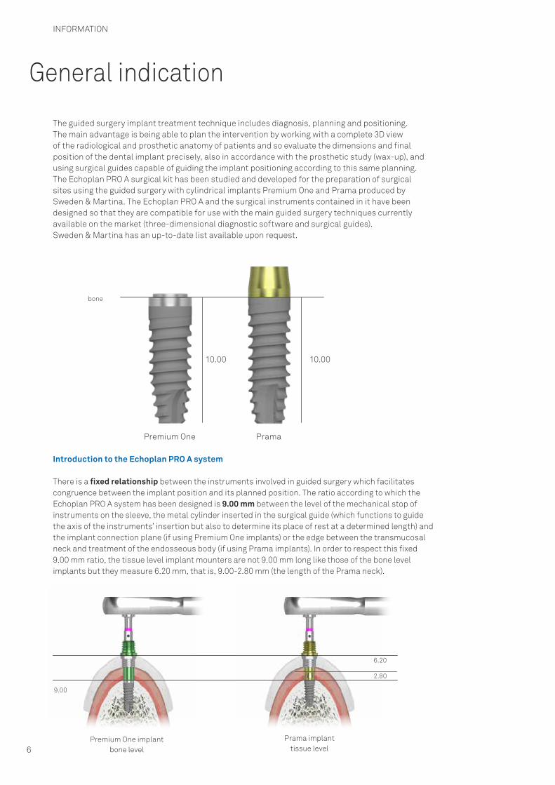
The guided surgery implant treatment technique includes diagnosis, planning and positioning. The main advantage is being able to plan the intervention by working with a complete 3D view of the radiological and prosthetic anatomy of patients and so evaluate the dimensions and final position of the dental implant precisely, also in accordance with the prosthetic study (wax-up), and using surgical guides capable of guiding the implant positioning according to this same planning.The Echoplan PRO A surgical kit has been studied and developed for the preparation of surgical sites using the guided surgery with cylindrical implants Premium One and Prama produced by Sweden & Martina. The Echoplan PRO A and the surgical instruments contained in it have been designed so that they are compatible for use with the main guided surgery techniques currently available on the market (three-dimensional diagnostic software and surgical guides). Sweden & Martina has an up-to-date list available upon request.
Introduction to the Echoplan PRO A system
There is a fixed relationship between the instruments involved in guided surgery which facilitates congruence between the implant position and its planned position. The ratio according to which the Echoplan PRO A system has been designed is 9.00 mm between the level of the mechanical stop of instruments on the sleeve, the metal cylinder inserted in the surgical guide (which functions to guide the axis of the instruments’ insertion but also to determine its place of rest at a determined length) and the implant connection plane (if using Premium One implants) or the edge between the transmucosal neck and treatment of the endosseous body (if using Prama implants). In order to respect this fixed 9.00 mm ratio, the tissue level implant mounters are not 9.00 mm long like those of the bone level implants but they measure 6.20 mm, that is, 9.00-2.80 mm (the length of the Prama neck).
10.00 10.00
bone
9.00
2.80
6.20
Premium One implantbone level
Prama implanttissue level
Premium One Prama

INFORMATION
7
When a surgical protocol provides for a different positioning of the implant platform from the juxtaosseous as in the XA* technique, the digital planning automatically calculates the position of the sleeve’s upper edge at exactly 9.00 mm from the connection plane. The thickness of the soft tissues in such cases may interfere with the ideal position of the sleeve so rather than adopting a flapless approach, the flap needs to be opened (A).
The opportunity to manage submerged positioning of implants is particularly helpful because the Premium One and Prama implant range also includes 6.00 mm and 7.00 mm heights and their dedicated drills are available as an option and can be added to the kit. In this case, please request the correct insertion sequence from Sweden & Martina.
*For further information on the XA technique, please go to www.sweden-martina.com
9.00 9.009.00
A
INFORMATION
8
Guide sleeves
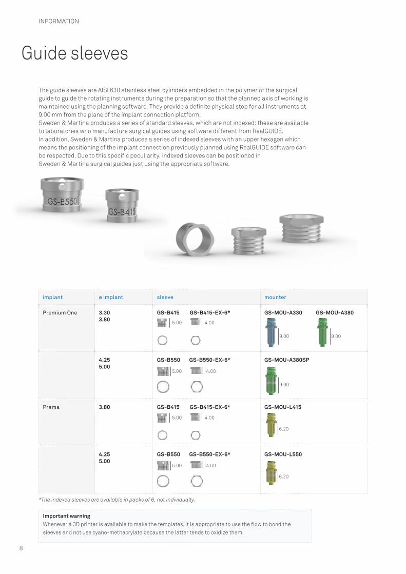
The guide sleeves are AISI 630 stainless steel cylinders embedded in the polymer of the surgical guide to guide the rotating instruments during the preparation so that the planned axis of working is maintained using the planning software. They provide a definite physical stop for all instruments at 9.00 mm from the plane of the implant connection platform.Sweden & Martina produces a series of standard sleeves, which are not indexed: these are available to laboratories who manufacture surgical guides using software different from RealGUIDE. In addition, Sweden & Martina produces a series of indexed sleeves with an upper hexagon which means the positioning of the implant connection previously planned using RealGUIDE software can be respected. Due to this specific peculiarity, indexed sleeves can be positioned in Sweden & Martina surgical guides just using the appropriate software.
implant ø implant sleeve mounter
Premium One 3.303.80
GS-B415 GS-B415-EX-6* GS-MOU-A330 GS-MOU-A380
4.255.00
GS-B550 GS-B550-EX-6* GS-MOU-A380SP
Prama 3.80 GS-B415 GS-B415-EX-6* GS-MOU-L415
4.255.00
GS-B550 GS-B550-EX-6* GS-MOU-L550
Important warningWhenever a 3D printer is available to make the templates, it is appropriate to use the flow to bond the sleeves and not use cyano-methacrylate because the latter tends to oxidize them.
5.00
5.00
4.00
4.00
5.00
5.00
4.00
4.00
9.00
9.00
9.00
6.20
6.20
*The indexed sleeves are available in packs of 6, not individually.
THE IMPLANTS
9
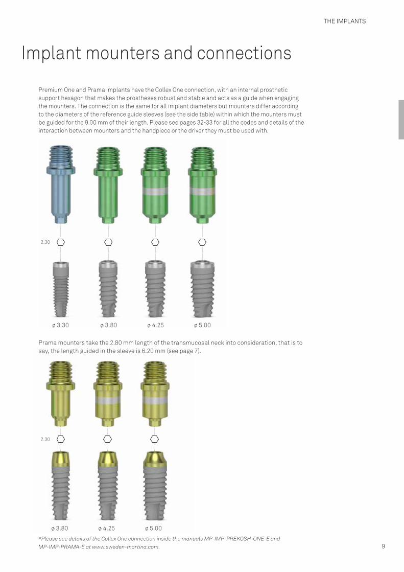
Implant mounters and connections
Premium One and Prama implants have the Collex One connection, with an internal prosthetic support hexagon that makes the prostheses robust and stable and acts as a guide when engaging the mounters. The connection is the same for all implant diameters but mounters differ according to the diameters of the reference guide sleeves (see the side table) within which the mounters must be guided for the 9.00 mm of their length. Please see pages 32-33 for all the codes and details of the interaction between mounters and the handpiece or the driver they must be used with.
2.30
2.30
*Please see details of the Collex One connection inside the manuals MP-IMP-PREKOSH-ONE-E and MP-IMP-PRAMA-E at www.sweden-martina.com.
Prama mounters take the 2.80 mm length of the transmucosal neck into consideration, that is to say, the length guided in the sleeve is 6.20 mm (see page 7).
ø 3.30 ø 3.80
ø 3.80
ø 4.25
ø 4.25
ø 5.00
ø 5.00

THE IMPLANTS
10
ø 4.25 ø 5.00
Premium One implants
implant ø and color code on the packaging
3.30 3.80 4.25 5.00
7.00 - - AS-ZT-425-070 AS-ZT-500-070
8.50 A-ZT-330-085 A-ZT-380-085 AS-ZT-425-085 AS-ZT-500-085
10.00 A-ZT-330-100 A-ZT-380-100 AS-ZT-425-100 AS-ZT-500-100
11.50 A-ZT-330-115 A-ZT-380-115 AS-ZT-425-115 AS-ZT-500-115
13.00 A-ZT-330-130 A-ZT-380-130 AS-ZT-425-130 AS-ZT-500-130
15.00 A-ZT-330-150 A-ZT-380-150 AS-ZT-425-150 AS-ZT-500-150
18.00 - A-ZT-380-180 AS-ZT-425-180 -
Surgical cover screws*
A-VT-330 A-VT-380 SH-VT-425-BL SH-VT-500-VI
15.00
ø 2.52
ø 3.30
13.00
ø 2.52
ø 3.30
11.50
ø 2.52
ø 3.30
10.00
ø 2.52
ø 3.30
8.50
ø 2.52
ø 3.30
15.00
ø 2.97
ø 3.80
13.00
ø 2.97
ø 3.80
11.50
ø 2.97
ø 3.80
10.00
ø 2.97
ø 3.80
8.50
ø 2.97
ø 3.80
18.00
ø 2.97
ø 3.80
18.00
ø 3.32
ø 4.25
15.00
ø 3.32
ø 4.25
13.00
ø 3.32
ø 4.25
11.50
ø 3.32
ø 4.25
10.00
ø 3.32
ø 4.25
8.50
ø 3.32
ø 4.25
15.00
ø 4.22
ø 5.00
13.00
ø 4.22
ø 5.00
11.50
ø 4.22
ø 5.00
10.00
ø 4.22
ø 5.00
8.50
ø 4.22
ø 5.00
7.00ø 3.32
7.00ø 4.22
*Each implant is sold with the respective 4 Gr. titanium surgical cover screws. Individual surgical cover screws are also available in sterile packs and are tightened at 8-10 Ncm.
See technical characteristics of Gr. 4 titanium on page 55.
ONE ONE

2.80
6.00
2.80 2.80
2.80
10.00
ø 5.00
2.80 2.80
2.80 2.80
13.00
2.80
15.00
ø 3.80ø 3.40
ø 2.97
2.80
15.00
ø 4.25ø 3.40
ø 3.32
2.80
15.00
ø 5.00ø 3.40
ø 4.22
2.80ø 5.00ø 3.40
ø 4.22
13.00
ø 4.25ø 3.40
ø 3.32
13.00
ø 3.80ø 3.40
ø 2.97
11.50
ø 5.00ø 3.40
ø 4.22
2.80
11.50
ø 4.25ø 3.40
ø 3.32
11.50
ø 3.80ø 3.40
ø 2.97
ø 3.40
ø 4.22
2.80
10.00
ø 4.25ø 3.40
ø 3.32
2.80
10.00
ø 3.80ø 3.40
ø 2.97
2.802.80
8.50
ø 3.80ø 3.40
ø 2.97
2.80
8.50
ø 4.25ø 3.40
ø 3.328.50
ø 5.00ø 3.40
ø 4.22
6.00
ø 5.00ø 3.40
ø 4.226.00
ø 4.25ø 3.40
ø 3.32
ø 3.80ø 3.40
ø 2.97
THE IMPLANTS
11
ø implant and color code on the packaging
3.80 4.25 5.00
6.00 LA-ZT-380-060 LA-ZT-425-060 LA-ZT-500-060
8.50 LA-ZT-380-085 LA-ZT-425-085 LA-ZT-500-085
10.00 LA-ZT-380-100 LA-ZT-425-100 LA-ZT-500-100
11.50 LA-ZT-380-115 LA-ZT-425-115 LA-ZT-500-115
13.00 LA-ZT-380-130 LA-ZT-425-130 LA-ZT-500-130
15.00 LA-ZT-380-150 LA-ZT-425-150 LA-ZT-500-150
Surgical cover screws
L-VT-340 L-VT-340 L-VT-340
Prama implants
See technical characteristics of Gr. 4 titanium on page 55.
N. B.: the implant’s nominal length expresses the endosseous length of the implant. Given the presence of the transmucosal neck, the total length is 2.80 mm greater than the nominal length.Each implant is sold with the respective 4 Gr. titanium surgical cover screws. Individual surgical cover screws are also available in sterile packs and are tightened at 8-10 Ncm.

SURGICAL INSTRUMENTS
12
General indications
The surgical instruments designed for use with the implant systems manufactured by Sweden & Martina are reusable medical devices intended for temporary use in the oral cavity (no more than 60 minutes) . The functions of the surgical instruments are to prepare sites for Sweden & Martina implants, to insert the implants in the sites, to tighten and unscrew all the connecting screws (surgical cover screws, healing abutments, screws for posts, abutments, prosthesic screws, transfer screws, etc.).
The surgical instruments manufactured by Sweden & Martina are designed for use with dentalimplants manufactured by Sweden & Martina. Use of surgical instruments for operations with other implants than those manufactured by Sweden & Martina limits the responsibility of Sweden & Martina and renders the product warranty void. Sweden & Martina declines all responsibility for use of any non-original instruments. Sweden & Martina surgical instruments are sold in NON-STERILE packs. Before use, they must be cleaned, disinfected and sterilized according to the instructions reported below. Failure to follow these warnings may expose the patient to infections. The materials used for production of the surgical instruments manufacturedby Sweden & Martina were selected based on the properties indicated for their intended useaccording to Directive 93/42/EEC, implemented in Italy with Law 46/97, Annex I – EssentialRequirements, point 7.1.
Each packaging indicates the code, description of the contents and batch number. These same details, which are also indicated on the labels inside the packs, must always be provided by the practitioner in any relevant correspondence.All the devices are identified by an instrument code, which is laser marked onto the body of each instrument. If there is not enough space to include the full code, the elements for unequivocally identifying the device (e.g. diameter or length) are provided. When handling the devices, both during use and during cleaning and sterilization procedures, it is recommended to use surgical gloves for personal protection from bacterial contaminations. Failure to follow these instructions may cause cross-infection.
Key to codes: surgical instruments
Implants are coded with “mnemonic” codes that allow easy identification of the piece. Below is a table showing how the mnemonic codes work using various types of instruments as examples.
examples component type and implant type
diameter length sleeve
The range of instruments is vast, we indicate some examples of the main families of instruments
The letters “GS” mean the instruments dedicated to guided surgery, designed to be guided inside the sleeves inserted in the surgical template
Normally it is the ø of the implant for the insertion or of the preparation for which the instrument should be used
This measurement is normally linked to the height of the component, or to other important measurements that characterise it, or it is a value that defines the preparation length of a drill
Indicates the internal diameter of the sleeve guiding the instrument
GS-F200-100-415 GS-F: drill for guided surgery
200: 2.00 mm 100: for the preparation of 10.00 mm high implants
415: for sleeves of 4.15 mm diameter
GS-MUC-550 GS-MUC: mucotome for guided surgery
- - 500: for sleeves of 5.50 mm diameter
GS-FPN-148 GS-FPN: drill for insertion of the surgical template retention pins
148: 1.48 mm - -

SURGICAL INSTRUMENTS
13
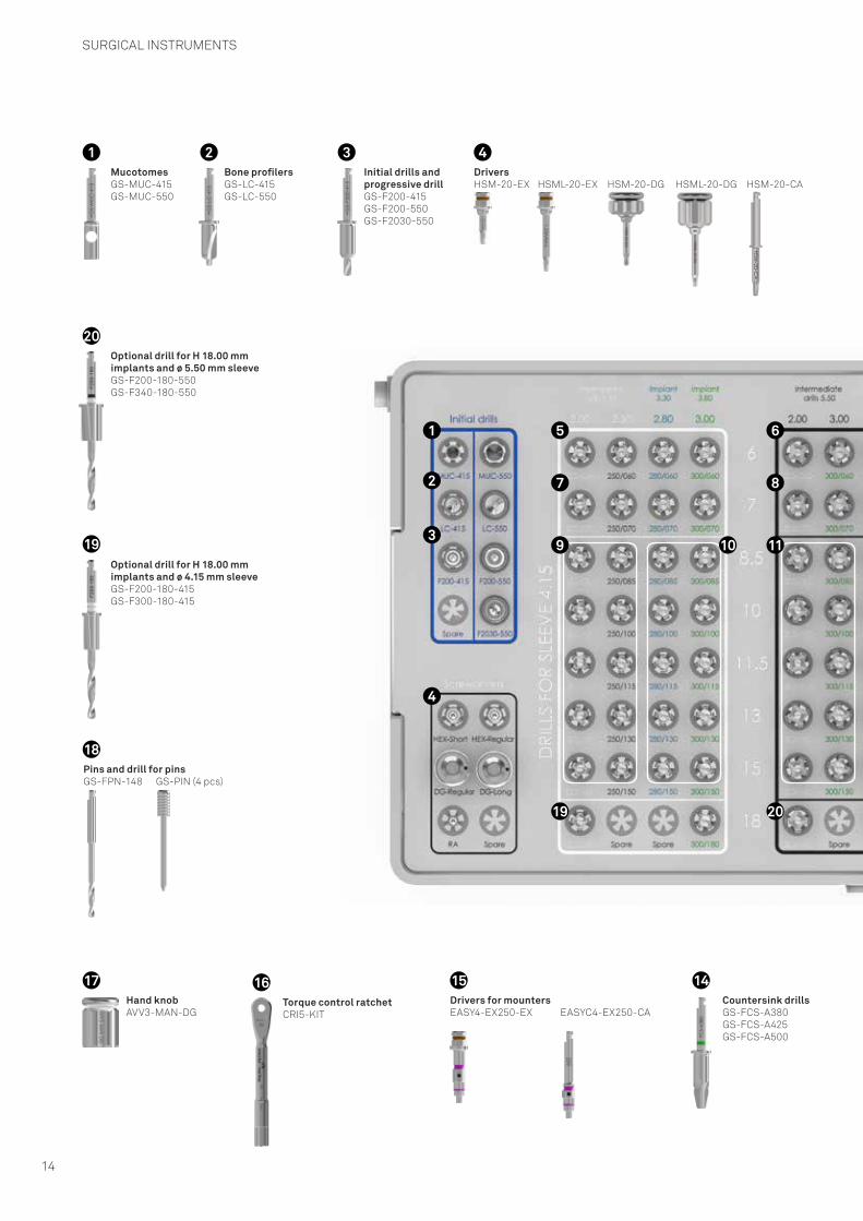
Echoplan PRO A surgical kit
The Echoplan PRO A surgical kit has been designed and produced to offer simplicity and immediacy of use for the correct sequence of the instruments. The instruments are all made of stainless steel for surgical use. They have the descriptions screen printed on the tray so that the user can easily identify each instrument and put it back in the correct place in the kit after the cleansing and cleaning phases thanks to the help of a system of color codes that track the appropriate surgical procedures for the various implant diameters.
The kit has holders for the optional drills used to prepare the 6.00 mm and 7.00 mm short implants and the 18.00 mm long implants.
Important warningThe Echoplan PRO A kit and the surgical instruments contained in it are sold in a NON-STERILE pack. Before being used, they must be cleaned, disinfected and sterilized according to the instructions provided below. Not respecting this warning may cause infections to the patient.
Important warningThe kit does not contain mounters which must be bought separately before the surgical operation. Mounters can be stored and organized in an appropriate organizer. For details see pages 30-31 and 34.
description code
Grommetless surgical kit complete with theInstruments required for guided insertionof Prama and Premium One implants
Grommetless instrument cases made of Radel for the guided surgery instruments,empty
ZGS-PRO-A-INT
GSPROA-TRAY-INT
SURGICAL INSTRUMENTS
14
MucotomesGS-MUC-415GS-MUC-550
1Bone profilersGS-LC-415GS-LC-550
2
Countersink drillsGS-FCS-A380GS-FCS-A425GS-FCS-A500
14Hand knobAVV3-MAN-DG
17
Initial drills and progressive drillGS-F200-415GS-F200-550GS-F2030-550
3 4
Torque control ratchetCRI5-KIT
16Drivers for mountersEASY4-EX250-EX EASYC4-EX250-CA
15
Optional drill for H 18.00 mmimplants and ø 5.50 mm sleeveGS-F200-180-550GS-F340-180-550
20
Optional drill for H 18.00 mmimplants and ø 4.15 mm sleeveGS-F200-180-415GS-F300-180-415
19
DriversHSM-20-EX HSML-20-EX HSM-20-DG HSML-20-DG HSM-20-CA
1
2
3
4
5 6
7 8
Pins and drill for pinsGS-FPN-148 GS-PIN (4 pcs)
18
9 10
19 20
11

SURGICAL INSTRUMENTS
15
Optional drills for H 6.00 mmø 3.80 mm implantsGS-F200-060-415GS-F250-060-415GS-F280-060-415GS-F300-060-415
5Optional drills for H 6.00 mm ø 4.25 and 5.00 mm implantsGS-F200-060-550GS-F300-060-550GS-F340-060-550GS-F425-060-550
6Optional drills for H 7.00 mm ø 3.80 mm implantsGS-F200-070-415GS-F250-070-415GS-F280-070-415GS-F300-070-415
7
Optional drills for H 7.00 mmø 4.25 and 5.00 mm implantsGS-F200-070-550GS-F300-070-550GS-F340-070-550GS-F425-070-550
8
Final drills for ø 4.15 mm sleeveGS-F280-085-415GS-F280-100-415GS-F280-115-415GS-F280-130-415GS-F280-150-415
GS-F300-085-415GS-F300-100-415GS-F300-115-415GS-F300-130-415GS-F300-150-415
10
Intermediate drills for ø 4.15 mm sleeve GS-F200-085-415GS-F200-100-415GS-F200-115-415GS-F200-130-415GS-F200-150-415
GS-F250-085-415GS-F250-100-415GS-F250-115-415GS-F250-130-415GS-F250-150-415
9
Intermediate drills for ø 5.50 mm sleeve GS-F200-085-550GS-F200-100-550GS-F200-115-550GS-F200-130-550GS-F200-150-550
GS-F300-085-550GS-F300-100-550GS-F300-115-550GS-F300-130-550GS-F300-150-550
11Final drills for ø 5.50 mm sleeveGS-F340-085-550GS-F340-100-550GS-F340-115-550GS-F340-130-550GS-F340-150-550
GS-F425-085-550GS-F425-100-550GS-F425-115-550GS-F425-130-550GS-F425-150-550
12Bone tapsGS-MS-330GS-MS-A380GS-MS-A425GS-MS-A500
13
13
14
15
18
17
16
12

SURGICAL INSTRUMENTS
16
Rotating instruments
All Sweden & Martina drills are made of surgical steel with high resistance to corrosion and wear. They are intended for mechanical use, i.e. they have a shank with a right angle attachment and must be used with a suitable micromotor. The extreme accuracy of design and production allows use completely free from vibrations and oscillations. However, incorrect insertion of the instruments in the handpiece will cause instrument vibration, eccentric rotation, early wear and shaft buckling. Suitable surgical micromotors only should be used. Micromotors should be checked regularly by their manufacturers, according to the indications given by the manufacturers, to prevent potential malfunctions (e.g. axle shifts for transmission shafts, worn orfaulty forceps, etc.).
Failure to follow the instructions provided may cause surgical complications and consequent damage to the patient‘s health. It is recommended to use the rotation speeds indicated in the procedures on page 60 and following to prevent the development of bone necrosis. Lever movements increase the risk of instrument breakage and should therefore be avoided. Changes in speed should be avoided in general. Never apply pressure such as to force the instrument to stop rotating. This could lead to an excessive increase in heat in the tissues being drilled, with consequent bone necrosis, and damage both the instrument and the appliance used (micromotor). This could also lead to breakage of the instrument. Using an intermittent approach, with a back and forth movement in a vertical direction, prevents overheating and wear of the working part and an undesirable increase in the temperature in the tissues being cut. Suitable coolant liquids must be used. Inadequate irrigation can lead to bone necrosis. Drill wear depends on a large extent on the type and density of the drilled bone: harder bone leads to greater instrument wear.For greater safety and caution, given the device’s capacity for resistance to wear, drills should notbe used for more than 20 work cycles and should be replaced earlier if the instruments lose their cutting ability. These recommended 20 cycles should be considered a rough guide. Always check the instrument’s residual cutting capacity after each procedure. Sweden & Martina declines all responsibility in cases of excessively intense use. Never sharpen drills before use. Never usedamaged, buckled or worn instruments.
Drills for guided surgery have been designed to work inside the sleeves produced by Sweden & Martina and inserted inside the surgical guides by the respective manufacturer.Sweden & Martina is not liable for any malfunctioning or damage caused by the use of guided surgery drills with non-original sleeves or incompatible with the size of instruments, which could get stuck, may not be guided correctly, or produce a different implant preparation from that planned by the clinician if the sleeve’s height is not correct.
Important warningThe Echoplan PRO A kit and the surgical instruments contained in it are sold in a NON-STERILE pack.Before being used, they must be cleaned, disinfected and sterilized according to the instructions provided below. Not respecting this warning may cause infections to the patient.
SURGICAL INSTRUMENTS
17
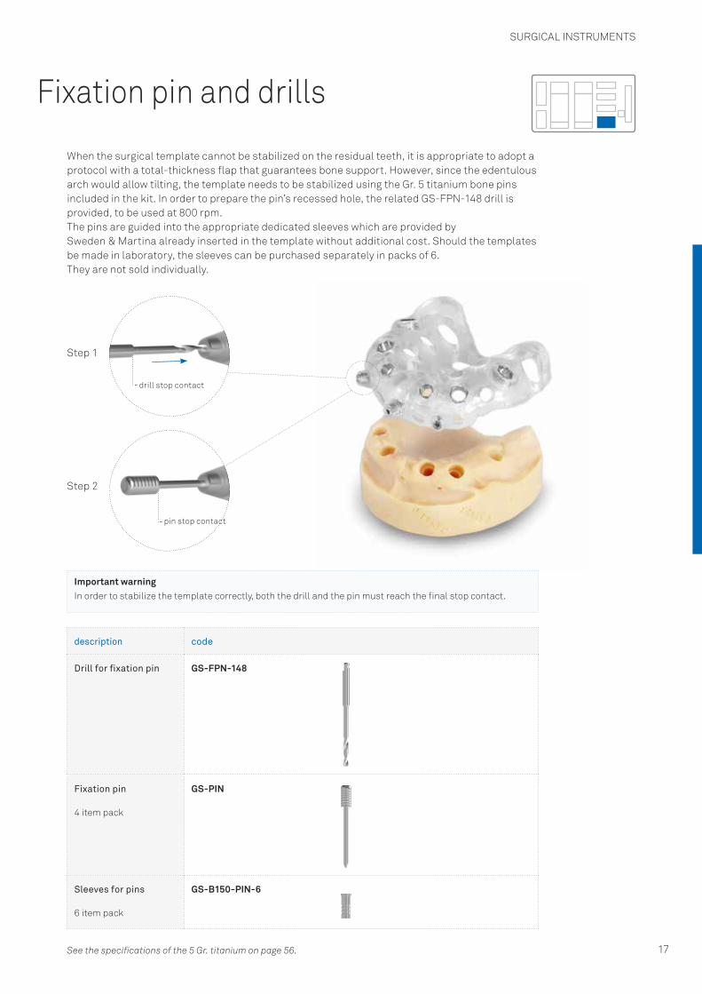
Important warningIn order to stabilize the template correctly, both the drill and the pin must reach the final stop contact.
Fixation pin and drills
When the surgical template cannot be stabilized on the residual teeth, it is appropriate to adopt a protocol with a total-thickness flap that guarantees bone support. However, since the edentulous arch would allow tilting, the template needs to be stabilized using the Gr. 5 titanium bone pins included in the kit. In order to prepare the pin’s recessed hole, the related GS-FPN-148 drill is provided, to be used at 800 rpm.The pins are guided into the appropriate dedicated sleeves which are provided by Sweden & Martina already inserted in the template without additional cost. Should the templates be made in laboratory, the sleeves can be purchased separately in packs of 6.They are not sold individually.
description code
Drill for fixation pin GS-FPN-148
Fixation pin
4 item pack
GS-PIN
Sleeves for pins
6 item pack
GS-B150-PIN-6
Step 1
drill stop contact
pin stop contact
Step 2
See the specifications of the 5 Gr. titanium on page 56.

SURGICAL INSTRUMENTS
18
From planning to implant insertion: stages in Echoplan guided surgery
Thanks to the potential of 3D simulation, the clinician is able to define exactly the diameter and height of the implant to be inserted using one of the numerous softwares on the market. The correct implant positioning is referred to the operator’s clinical experience and to the accuracy of the chosen software. The Echoplan PRO A kit can be used with all softwares respecting a stop contact distance for the instruments fixed at 9.00 mm from the implant platform.
The choice of the guide sleeve to be inserted in the template is made by the template manufacturer and is bound by the diameter of the implant chosen. See page 8 for information about the sleeves that Sweden & Martina manufactures for the production of the surgical templates. After identifying the diameter of the sleeve to be used, it is possible to prepare the surgical site using the appropriate surgical instruments from the Echoplan PRO A kit for the sleeve diameter.
Site preparation must proceed with the sequential use of three surgical accessories included in the kit, which are the following: mucotome, the bone profiler and the initial drill. The shape of the drill tips allows a hole with a diameter of 2.00 mm and a depth of 4.50 mm (A) to be bored. In this way the final drills that are used subsequently are guided from the first millimetres onwards at the tip (for 4.50 mm by the hole bored by the initial drill) and in the guide sleeve. The illustration below visually helps to understand the importance of these three initial steps.All three instruments are included in the kit in both the versions for the ø 4.15 mm and the ø 5.50 mm sleeve.
guide sleeve
mucosa
bone
4.00
5.009.00
ø 2.00 ø 2.00
ø 2.80
4.50 4.50 4.50
11.50
A
Pilot drill guided step
SURGICAL INSTRUMENTS
19
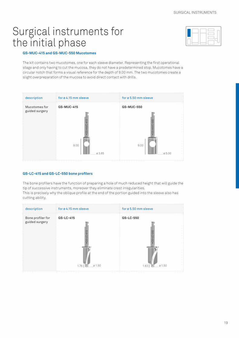
Surgical instruments for the initial phase
GS-MUC-415 and GS-MUC-550 Mucotomes
The kit contains two mucotomes, one for each sleeve diameter. Representing the first operational stage and only having to cut the mucosa, they do not have a predetermined stop. Mucotomes have a circular notch that forms a visual reference for the depth of 9.00 mm. The two mucotomes create a slight overpreparation of the mucosa to avoid direct contact with drills.
GS-LC-415 and GS-LC-550 bone profilers
The bone profilers have the function of preparing a hole of much reduced height that will guide the tip of successive instruments, moreover they eliminate crest irregularities.This is precisely why the oblique profile at the end of the portion guided into the sleeve also has cutting ability.
description for ø 4.15 mm sleeve for ø 5.50 mm sleeve
Mucotomes for guided surgery
GS-MUC-415 GS-MUC-550
description for ø 4.15 mm sleeve for ø 5.50 mm sleeve
Bone profiler for guided surgery
GS-LC-415 GS-LC-550
ø 3.85
ø 1.50 ø 1.50
ø 5.00
9.00
1.76 1.63
9.00

SURGICAL INSTRUMENTS
20
Initial drills GS-F200-415 and GS-F200-550
The third compulsory stage involves two initial drills, one for each sleeve diameter, to be used always regardless of the implant system.The drills create a hole with a depth of 4.50 mm, so that the subsequent drills can be guided doubly, both at the tip, because this is inserted in the guide hole already drilled, and by the stop that is guided inside the sleeve at a higher position.
GS-F2030-550 progressive drill
A progressive drill is available to widen the preparation from ø 2.00 mm to ø 3.00 mm so that the ø 3.00 mm intermediate drills for a ø 5.50 mm sleeve can be guided. The drill is used after the ø 2.00 mm intermediate drill. The correct sequence for using the progressive drill is shown on page 41.
description for ø 4.15 mm sleeve for ø 5.50 mm sleeve
Initial drills for guided surgery
GS-F200-415 GS-F200-550
ø 2.00 ø 2.004.50 4.50
0.58 0.58
description for ø 5.50 mm sleeve
ø 2.00 - 3.00 mm Progressive drill
GS-F2030-550
ø 3.00
7.50 ø 2.50ø 2.00
SURGICAL INSTRUMENTS
21
Intermediate and final drills
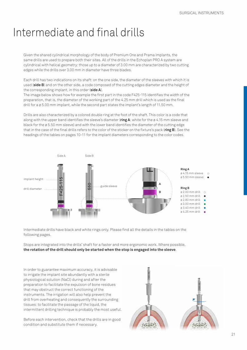
Given the shared cylindrical morphology of the body of Premium One and Prama implants, the same drills are used to prepare both their sites. All of the drills in the Echoplan PRO A system are cylindrical with helical geometry: those up to a diameter of 3.00 mm are characterized by two cutting edges while the drills over 3.00 mm in diameter have three blades.
Each drill has two indications on its shaft: on the one side, the diameter of the sleeves with which it is used (side B) and on the other side, a code composed of the cutting edges diameter and the height of the corresponding implant, in this order (side A).The image below shows how for example the first part in the code F425-115 identifies the width of the preparation, that is, the diameter of the working part of the 4.25 mm drill which is used as the final drill for a ø 5.00 mm implant, while the second part states the implant’s length of 11.50 mm.
Drills are also characterized by a colored double ring at the foot of the shaft. This color is a code that along with the upper band identifies the sleeve’s diameter (ring A: white for the ø 4.15 mm sleeve and black for the ø 5.50 mm sleeve) and with the lower band identifies the diameter of the cutting edge that in the case of the final drills refers to the color of the sticker on the fixture’s pack (ring B). See the headings of the tables on pages 10-11 for the implant diameters corresponding to the color codes.
Side A Side B
implant height
guide sleevedrill diameter
In order to guarantee maximum accuracy, it is advisable to irrigate the implant site abundantly with a sterile physiological solution (NaCl) during and after the preparation to facilitate the expulsion of bone residues that may obstruct the correct functioning of the instruments. The irrigation will also help prevent the drill from overheating and consequently the surrounding tissues: to facilitate the passage of the liquid, the intermittent drilling technique is probably the most useful.
Before each intervention, check that the drills are in good condition and substitute them if necessary.
Intermediate drills have black and white rings only. Please find all the details in the tables on the following pages.
Stops are integrated into the drills’ shaft for a faster and more ergonomic work. Where possible, the rotation of the drill should only be started when the stop is engaged into the sleeve.
B
A
Ring A ø 4.15 mm sleeveø 5.50 mm sleeve
Ring B ø 2.00 mm drillø 2.50 mm drillø 2.80 mm drillø 3.00 mm drillø 3.40 mm drillø 4.25 mm drill

SURGICAL INSTRUMENTS
22
description for ø 4.15 mm sleeve
Drills for preparing H 8.50 mm implants
GS-F200-085-415 GS-F250-085-415 GS-F280-085-415 GS-F300-085-415
Drills for preparing H 10.00 mm implants
GS-F200-100-415 GS-F250-100-415 GS-F280-100-415 GS-F300-100-415
Drills for preparing H 11.50 mm implants
GS-F200-115-415 GS-F250-115-415 GS-F280-115-415 GS-F300-115-415
Drills for preparing H 13.00 mm implants
GS-F200-130-415 GS-F250-130-415 GS-F280-130-415 GS-F300-130-415
Drills for preparing H 15.00 mm implants
GS-F200-150-415 GS-F250-150-415 GS-F280-150-415 GS-F300-150-415
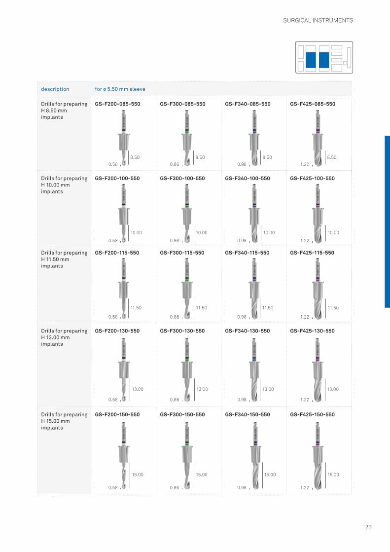
Drills provided with the Echoplan PRO A kit
0.58 0.72 0.81 0.86
0.86
0.86
0.86
0.86
0.81
0.81
0.81
0.81
0.72
0.72
0.72
0.72
0.58
0.58
0.58
0.58
8.50
10.00
11.50 11.50
13.00 13.00 13.0013.00
15.00 15.00 15.00 15.00
11.50 11.50
10.00 10.00 10.00
8.50 8.50 8.50
SURGICAL INSTRUMENTS
23
description for ø 5.50 mm sleeve
Drills for preparing H 8.50 mm implants
GS-F200-085-550 GS-F300-085-550 GS-F340-085-550 GS-F425-085-550
Drills for preparing H 10.00 mm implants
GS-F200-100-550 GS-F300-100-550 GS-F340-100-550 GS-F425-100-550
Drills for preparing H 11.50 mm implants
GS-F200-115-550 GS-F300-115-550 GS-F340-115-550 GS-F425-115-550
Drills for preparing H 13.00 mm implants
GS-F200-130-550 GS-F300-130-550 GS-F340-130-550 GS-F425-130-550
Drills for preparing H 15.00 mm implants
GS-F200-150-550 GS-F300-150-550 GS-F340-150-550 GS-F425-150-550
0.58
0.58
0.58
0.58
0.58
0.86
0.86
0.86
0.86
0.86
0.98
0.98
0.98
0.98
0.98
1.22
1.22
1.22
1.22
1.22
8.50
10.00
11.50 11.50
13.00 13.00 13.0013.00
15.00 15.00 15.00 15.00
11.50 11.50
10.00 10.00 10.00
8.50 8.50 8.50
SURGICAL INSTRUMENTS
24
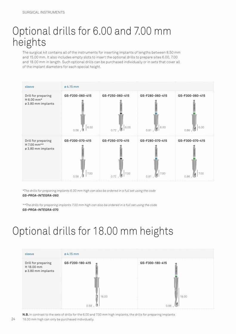
Optional drills for 6.00 and 7.00 mm heights
Optional drills for 18.00 mm heights
The surgical kit contains all of the instruments for inserting implants of lengths between 8.50 mm and 15.00 mm. It also includes empty slots to insert the optional drills to prepare sites 6.00, 7.00 and 18.00 mm in length. Such optional drills can be purchased individually or in sets that cover all of the implant diameters for each special height.
sleeve ø 4.15 mm
Drill for preparing H 6.00 mm* ø 3.80 mm implants
GS-F200-060-415 GS-F250-060-415 GS-F280-060-415 GS-F300-060-415
Drill for preparing H 7.00 mm** ø 3.80 mm implants
GS-F200-070-415 GS-F250-070-415 GS-F280-070-415 GS-F300-070-415
sleeve ø 4.15 mm
Drill for preparing H 18.00 mm ø 3.80 mm implants
GS-F200-180-415 GS-F300-180-415
*The drills for preparing implants 6.00 mm high can also be ordered in a full set using the code GS-PROA-INTEGRA-060.
**The drills for preparing implants 7.00 mm high can also be ordered in a full set using the code GS-PROA-INTEGRA-070.
N.B. in contrast to the sets of drills for the 6.00 and 7.00 mm high implants, the drills for preparing implants 18.00 mm high can only be purchased individually.
0.58
0.58
0.58 0.86
0.72
0.72
0.81
0.81
0.86
0.86
6.00
7.00
18.00 18.00
6.00
7.00
6.00
7.00
6.00
7.00
SURGICAL INSTRUMENTS
25
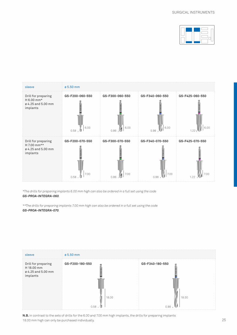
sleeve ø 5.50 mm
Drill for preparing H 6.00 mm* ø 4.25 and 5.00 mm implants
GS-F200-060-550 GS-F300-060-550 GS-F340-060-550 GS-F425-060-550
Drill for preparing H 7.00 mm** ø 4.25 and 5.00 mm implants
GS-F200-070-550 GS-F300-070-550 GS-F340-070-550 GS-F425-070-550
sleeve ø 5.50 mm
Drill for preparing H 18.00 mm ø 4.25 and 5.00 mm implants
GS-F200-180-550 GS-F340-180-550
*The drills for preparing implants 6.00 mm high can also be ordered in a full set using the code GS-PROA-INTEGRA-060.
**The drills for preparing implants 7.00 mm high can also be ordered in a full set using the codeGS-PROA-INTEGRA-070.
N.B. in contrast to the sets of drills for the 6.00 and 7.00 mm high implants, the drills for preparing implants 18.00 mm high can only be purchased individually.
0.58 0.86 0.98 1.22
0.58 0.98
0.58 0.86 0.98 1.22
6.00 6.00 6.00 6.00
18.00 18.00
7.00 7.00 7.00 7.00

SURGICAL INSTRUMENTS
26
Bone taps
These are bladed instruments able to prepare bone to receive the implants’ thread, in very compact or cortical bone in order to alleviate the compression and decrease the insertion torque. All of the bone taps have a total length of insertion in the bone of 6.00 mm and are composed of a guide section that does not cut, and a cutting section of 5.50 mm, indipendent from the length of the implant to be inserted. Each implant diameter has a dedicated bone tap. Premium One and Prama systems have the same bone taps because they share the same endosseous morphology.
description ø 3.30 ø 3.80 ø 4.25 ø 5.00
Bone taps for Premium One and Prama implants
GS-MS-330 GS-MS-A380 GS-MS-A425 GS-MS-A500
Important warningEven in very mineralized bone it is not advisable to bone tap the preparations for 6.00 and 7.00 mm height implants.
6.00 6.00 6.00 6.00

SURGICAL INSTRUMENTS
27
description ø 3.30 ø 3.80 ø 4.25 ø 5.00
Countersink drills for Premium One and Prama implants
- GS-FCS-A380 GS-FCS-A425 GS-FCS-A500
ø 3.841.564.04
ø 4.241.564.04
ø 4.991.564.04
Countersink drillsIn the case of excessive friction caused by the coronal cortical bone, the neck of the implant can be prepared using the appropriate four-edged countersink drills included in the surgical kit. The countersink drills are universal because they can be used for both a cylindrical preparation for the neck of Premium One implants and for the cylindrical portion of Prama implants.
Important warningEven in very mineralized bone it is not advisable to use the countersink drill for the preparations of 6.00 mm height implants.

SURGICAL INSTRUMENTS
28
The surgical kit contains several useful screwdrivers for tightening and unscrewing mounter fixation screws, healing abutments, transfer screws, post and abutments screws. All of the screwdrivers are made of stainless steel for surgical use. The design of the tip of all of the screwdrivers is the same so they are all interchangeable. They are available in different total lengths and in digital and one-piece version, that is to say, solid with a handpiece that can be gripped, or equipped with a hexagonal connector compatible with the ratchet.The one-piece hand drivers in the kit are available in two different heights.
Important warningIt is recommended to pass a thread through the hole on the top of the digital screwdriver to prevent it from falling.
Important warningLever movements should be avoided as they increase the risk of breakage. Before tightening, make sure the hexagonal socket screw head on the driver tip is correctly inserted into the screws to be tightened. Incorrect insertion is likely to pare off the hexagonal connection of the screwdriver or the screw to be tightened. Drivers have a slightly conical profile, able to guarantee the hexagonal connection on the tip of the drivergrips inside the hexagonal connection on the head of the screws, making it possible to carry the screw to the patient’s mouth correctly, without dropping it. Replace drivers regularly to reduce the risk of wear to the hexagon connection.
description code
Hand driver for surgical cover screws and fixation screws, digital, short
HSM-20-DG
Hand driver for surgical cover screws and fixation screws, digital, long
HSML-20-DG
Important warningExcessive torque can strip the fixation screws’ slots and round off the corners of the screwdrivers causing intraoperative or prosthetic complications that can be serious. The recommended torques for tightening the various components are summarized in the following table:
description recommended torque
surgical cover screws, healing abutments (manually) 8-10 Ncm
all of the prosthetic screws 20-25 Ncm
all of the prosthetic components with direct screw retention on the implant 25-30 Ncm
transfer fixation screws (manually) 8-10 Ncm
Drivers for connecting screws
12.30
21.05
14.80
26.85

25.00
31.00
15.00
21.00
SURGICAL INSTRUMENTS
29
description code
Hand knob for bone taps, mounters, drivers and manual drivers
AVV3-MAN-DG
description code
Screwdriver for fixation screws, with hexagonal connector for torque control ratchet or hand knob, short
HSM-20-EX
Screwdriver for fixation screws, with hexagonal connector for torque control ratchet or hand knob, long
HSML-20-EX
Screwdriver for fixation screws, with hexagonal connector for torque control ratchet or hand knob, extra long*
HSMXL-20-EX
Screwdriver, with right angle shank for fixation screws
HSM-20-CA
Prosthetic screwdrivers
In order to facilitate the engagement of the screws or the threaded portions of the prosthetic components, tightening can be started using the digital screwdrivers. Nevertheless, given the importance of the tightening torque, it is advisable to use screwdrivers with hexagonal connectors in this phase, keeping the torque under control with the applied use of the torque wrench.
Important warningAll the ratchet drivers have a red polymer O-ring in the connecting hexagon that guarantees friction between the instruments and therefore a correct grip of the components. This O-ring must be checked periodically and replaced when worn or when no longer able to exert the correct friction. A kit of 5 spare O-rings is available, which can be ordered with code ORING180-088.
7.90
13.90
12.60
27.00
*Optional instrument not included in the surgical kit but purchased separately
Hand knob

SURGICAL INSTRUMENTS
30
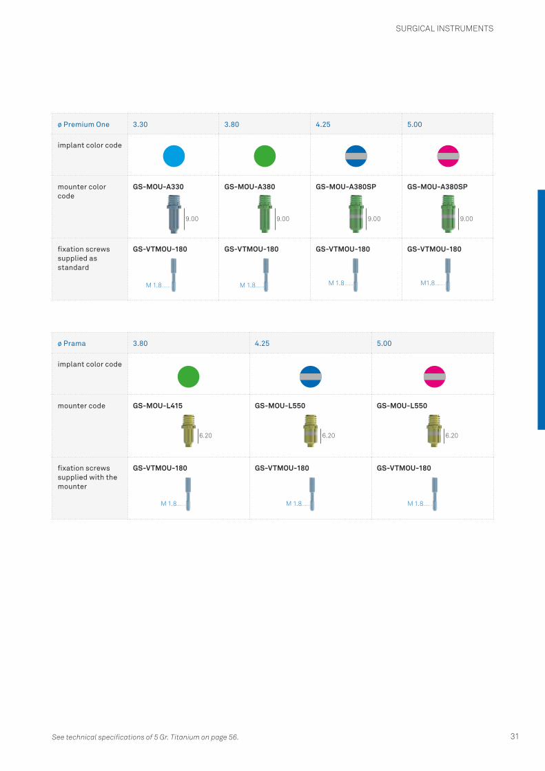
Mounters
Mounters are used to ensure that final implant insertion is also guided, not only in terms of angle and depth but also of orientation. In fact, mounters have a hexagonal landmark with faces aligned with the faces of the implant connections (A). They are made in 5 Gr. Titanium, anodized according to the color code shown in the table below and are supplied together with the specific screw, the same for all implant diameters, to be tightened manually with a torque no greater than 10 Ncm.
Mounters can be organized, sterilized and preserved in the dedicated Mounter Organizer illustrated on page 34.
Mounters for Premium One implants
Mounters for Prama implants
Important warningIn order to meet the clinical needs of every individual case, both Premium One and Prama implants can be positioned more deeply (see page 7). For help in advance in the planning stage of these cases, it is advisable to call Sweden & Martina personnel dedicated to guided surgery. The support service for guided surgery can be contacted by phone on +39 049 9124248.
A
A
SURGICAL INSTRUMENTS
31
ø Premium One 3.30 3.80 4.25 5.00
implant color code
mounter color code
GS-MOU-A330 GS-MOU-A380 GS-MOU-A380SP GS-MOU-A380SP
fixation screws supplied as standard
GS-VTMOU-180 GS-VTMOU-180 GS-VTMOU-180 GS-VTMOU-180
ø Prama 3.80 4.25 5.00
implant color code
mounter code GS-MOU-L415 GS-MOU-L550 GS-MOU-L550
fixation screws supplied with the mounter
GS-VTMOU-180 GS-VTMOU-180 GS-VTMOU-180
9.00
6.20 6.20 6.20
9.00 9.00 9.00
M 1.8
M 1.8 M 1.8 M 1.8
M 1.8 M 1.8 M1.8
See technical specifications of 5 Gr. Titanium on page 56.

SURGICAL INSTRUMENTS
32
Easy Insert Driver for mounters
The Echoplan PRO A surgical kit includes two Easy Insert drivers with a metal O-ring that clicks inside the upper end of all of the mounters, making certain of the assembled implant-mounter’s transport into the sleeve and of the surgical insertion phases.These drivers have been tested up to a torque of 70 Ncm. Greater insertion torque can cause mechanical criticality. It is advisable to use Easy Insert with hexagon in all of the later inserting phases.
Important warningThe Easy Insert drivers for mounters cannot be used to directly engage Premium One and Prama implants: their dimensions only allow them to be used with guided surgery mounters.They are supplied pre-mounted with the appropriate titanium O-ring. Being mechanical components, these small retention rings are subject to wear and can lose their elasticity and functionality with the passage of time and cannot be replaced. On the other hand, the instrument in its entirety can be replaced. Easy Inserts have been tested to resist up to 50 uses in the most unfavorable use conditions. Consequently, this limit can vary according to the conditions of use. They have a guiding pin on the tip that facilitates insertion into the mounter. Lever movements can cause the driver to bend or fracture with intraoperative surgical complications being possible.
description code
Easy Insert Driver for guided surgery mounters with hexagonal connector for torque control ratchet
EASY4-EX250-EX
Easy Insert Driver for guided surgery mounters with right-angle attachmen
EASYC4-EX250-CA
Driver for implant insertion with attachment for right-angle driver, code EASYC4-EX250-CA
Connection geometry for the digital insertion driver (code EASY4-EX250-EX) or for right-angle driver (code EASYC4-EX250-CA)
Implant/mounter fixation screws with M 1.8 threading, code GS-VTMOU-180
Mounter for ø 3.80 mm Premium One Implant code GS-MOU-A380
ø 3.80 mm Premium One Implant code A-ZT-380-130
SURGICAL INSTRUMENTS
33
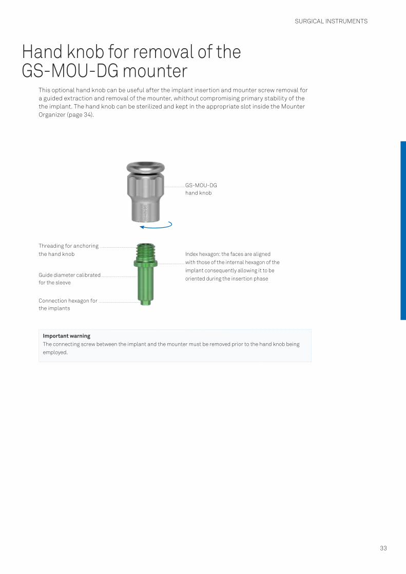
Hand knob for removal of the GS-MOU-DG mounter
This optional hand knob can be useful after the implant insertion and mounter screw removal for a guided extraction and removal of the mounter, whithout compromising primary stability of the the implant. The hand knob can be sterilized and kept in the appropriate slot inside the Mounter Organizer (page 34).
Index hexagon: the faces are aligned with those of the internal hexagon of the implant consequently allowing it to be oriented during the insertion phase
Threading for anchoring the hand knob
GS-MOU-DG hand knob
Guide diameter calibrated for the sleeve
Connection hexagon for the implants
Important warningThe connecting screw between the implant and the mounter must be removed prior to the hand knob being employed.

GSMOUNT-TRAY-INT Mounter OrganizerThe Mounter Organizer is an autoclavable tray made of radel for organizing, sterilizing and housing the mounters for guided surgery. The upper half has two areas of 20 slots each to subdivide the instruments according to the size of the sleeve that they must be used with. There is a removable stainless steel surgical bowl in the middle of the tray to put the used mounters back after they have been removed.The lower part has a retainer for the hand knob, 4 slots to house instruments with hexagonal connector and with right-angle shaft and 7 retentive slots to house the implant vials that make the phases of assembling the mounter to the fixture easier.
Important warningThe Mounter Organizer is a tray which is sold empty and does not include any instruments. It is appropriate to remove and clean the surgical stainless steel bowl before the sterilization phase and then to put it back.
Area to put the mounters for ø 4.15 mm sleeves
Area to put the mounters for ø 5.50 mm sleeves
Area with retentive slots for the implant vials to make the assembly of the mounter to the implant easier
SURGICAL INSTRUMENTS
34

Ratchet head cover
Wheel pawl
Ratchet head Handle Guide pin Spring
Torque adjustment screws
Hexagonal tip of the torque-adjusting screw
Wheel stop tooth
Cover fixation screws
CRI5-KIT torque control ratchet
A specific ratchet (CRI5-KIT) is included inside the Echoplan PRO A surgical kit together with the adjustment key that is used to rapidly turn the torque adjustment sleeve. A gel lubricant for maintenance is also included. The ratchet can be used with torque adjustment from 10 to 70 Ncm or otherwise in a blocked position without torque control.If using it as a prosthetic ratchet to tighten the screws, reference should be made to the torque values shown in the table on page 28. The CRI5-KIT counter torque ratchet is a multiuse dismantlable instrument sold non-sterile.
Before each use, this instrument must be cleaned and sterilized according to the instructions on pages 51-52. Appropriate maintenance is fundamental to the correct functioning of the device so that its reliability and operating life are not affected. This is carried out by following all of the phases in dismantling and correct reassembly of the device in detail step by step during its cleaning.Personnel who operate this instrument must be trained appropriately and have read the instructions in this manual before handling this instrument.Once sterilized, the ratchet is ready for use. A test verifying the correct assembly and functioning of the ratchet is necessary before each and every time it is operated, whether surgically or prosthetically.
The torque is adjusted by aligning the marking of the value required in the circular opening in the handle. The “IN” arrow on the head seen from above indicates the ratchet position that allows the screw to be tightened. The “OUT” arrow on the head visible from above indicates the loosening position. An unlimited torque position is obtained by positioning the torque adjustment device to the notch marked “R” on the handle of the ratchet body.
SURGICAL INSTRUMENTS
35

The sleeve can be screwed and unscrewed manually but to speed up these operations, the kitalso contains a driver that allows you to rotate it quickly.Any deterioration in the screw retention, insertion and coupling mechanisms must be checked by personnel responsible for the use and maintenance of this dental instrument. The parts in this mechanism are not interchangeable. A part of a ratchet cannot be taken to substitute another as each ratchet is calibrated INDIVIDUALLY. Should a part be lost, please return the instrument affected to Sweden & Martina so that it can be repaired. No component for the assembly of the ratchet is sold separately. Not respecting the instructions provided may cause problems with the stability and maintenance of the prosthesis.
Important warningThe torque is always adjusted by tightening/unscrewing the sleeve placed at the bottom the instrument’s handle. The torque must always be adjusted by increasing the value, starting by screwing at a lower value up until arriving to the desired torque, that is to say, tightening the sleeve in a clockwise direction. Consequently, whenever a torque below the last one used needs adjusting, a two turn screwing must be used below the value of the new torque desired and then increased to the desired value, re-screwing the sleeve clockwise.
To adjust the torque to increase it, the sleeve simply needs to be rotated in a clockwise direction.
To adjust the torque to a value below that previously used, the sleeve must be turned anticlockwise no less than two turns below the desired value and then proceed to screw in a clockwise direction until reaching the value of torque required.
SURGICAL INSTRUMENTS
36

Dynamometric key with TWL control lever
A specific TWL dynamometric key with control lever is available to buy separately. The dynamometric key can be used to indicate the value of torque applied during the surgical phases of screw retention and unscrewing, with marked values from 10 to 90 Ncm. It is supplied with a dedicated adaptor that means it can be used with the surgical instruments with hexagonal attachments.The TWL dynamometric key with control lever is a dismantlable multipurpose instrument sold non-sterile.
Before each use, this instrument must be cleaned and sterilized according to the instructions on pages 53-54.Appropriate maintenance is fundamental to the correct functioning of the device and so that its reliability is not affected. This is carried out by following all phases in dismantling and correct reassembly of the device step by step in detail during its cleaning.Personnel who operate this instrument must be trained appropriately and have read the instructions in this manual before handling this instrument.
After sterilization and before using it, make sure that the first notch on the scale is aligned with the arrow. A test to check correct mounting and functioning of the ratchet needs to be carried out before each time it is used.
Wheel pawl/Adaptor
Ratchet head Handle
The dynamometric key can be used as a fixed key or without using the dynamometric scale by levering the whole handle. In this case it is recommended not to subject it to a load greater than 150 Ncm.Any deterioration in the screw retention, insertion and coupling mechanisms must be checked by personnel responsible for the use and maintenance of this instrument.The parts of this dynamometric key are not interchangeable so a part cannot be used to substitute another in the key. Should a part be lost, please return the instrument affected to Sweden & Martina so that it can be repaired. No component for assembling the dynamometric key with control lever can be sold separately. Not respecting the instructions provided can cause the patient to have esthetic problems and may damage the patient’s health.
Important warningDuring the use of the dynamometric key’s lever, it must not pass the graduated scale as this can cause imprecise reading of the torque and damage the instrument.
SURGICAL INSTRUMENTS
37

Preparation of the implant site
During the software-assisted planning it is best as a rule to keep a distance of 3.00 mm between the perimeters of the implants and at least 2.00 mm between implants and adjacent natural teeth. Numerous clinical trials and experimental studies state that it is appropriate to position the implants more lingually or palately in order to obtain better esthetic results since such positioning helps to preserve the level of the soft and hard tissues coronally to the implant. It is also essential to check that the thickness of the residual osseous wall is not less than 1.00 mm.The best esthetic results are obtained with buccal walls of no less than 2.00 mm. The risk of bone resorption and exposure of the threads increases if thicknesses are thinner.
3.00 mm 2.00 mm
The appropriate preparation sequences for the Premium One and Prama implants are described in the following pages. These procedures have been developed through clinical experience and information from numerous clinical trials and protocols for implants with this endosseous morphology. However, it must always be taken into consideration that types of bone with different densities need different surgical approaches and the instructions that follow cannot and are not meant to substitute the required training, medical knowledge nor personal experience that sometimes suggests different indications. The sequences that follow, however, refer to specific bone types.
It should be borne in mind that standard drills always prepare a hole longer than the implant. Please see pages 22 and following for the dimensions of the overpreparation. The preparations must be atraumatic and the most gradual possible as well as be carried out quickly and accurately. The bone must not be overheated.
It should also be borne in mind that the surgical micromotor needs to be set to the correct torque, reduction and rotation values accordingly to the intervention that needs to be carried out. In particular:• drills must be used at the speed stated in each single sequence, with maximum torque and
irrigated abundantly with cold sterile physiological solution, better if it has been cooled in a refrigerator;
• the bone taps must only be used when stated in the procedures.
SURGICAL SEQUENCES
38
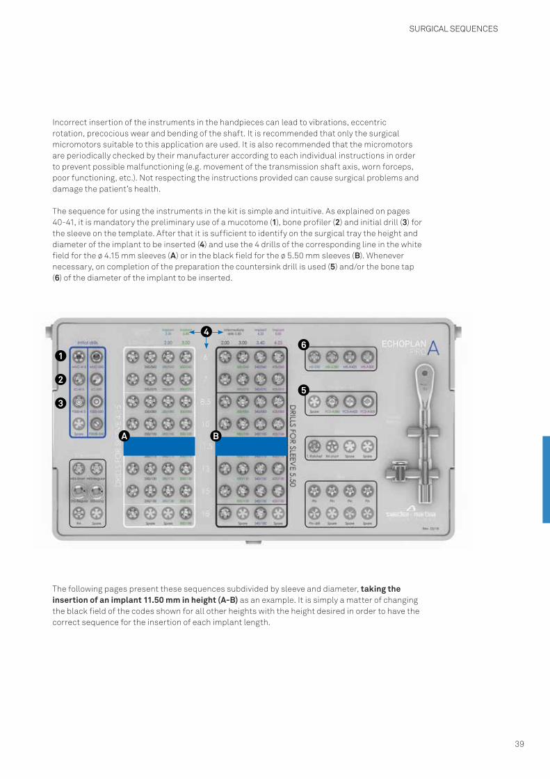
Incorrect insertion of the instruments in the handpieces can lead to vibrations, eccentric rotation, precocious wear and bending of the shaft. It is recommended that only the surgical micromotors suitable to this application are used. It is also recommended that the micromotors are periodically checked by their manufacturer according to each individual instructions in order to prevent possible malfunctioning (e.g. movement of the transmission shaft axis, worn forceps, poor functioning, etc.). Not respecting the instructions provided can cause surgical problems and damage the patient’s health.
The following pages present these sequences subdivided by sleeve and diameter, taking the insertion of an implant 11.50 mm in height (A-B) as an example. It is simply a matter of changing the black field of the codes shown for all other heights with the height desired in order to have the correct sequence for the insertion of each implant length.
1
2
3
46
5
BA
The sequence for using the instruments in the kit is simple and intuitive. As explained on pages 40-41, it is mandatory the preliminary use of a mucotome (1), bone profiler (2) and initial drill (3) for the sleeve on the template. After that it is sufficient to identify on the surgical tray the height and diameter of the implant to be inserted (4) and use the 4 drills of the corresponding line in the white field for the ø 4.15 mm sleeves (A) or in the black field for the ø 5.50 mm sleeves (B). Whenever necessary, on completion of the preparation the countersink drill is used (5) and/or the bone tap (6) of the diameter of the implant to be inserted.
SURGICAL SEQUENCES
39
SURGICAL SEQUENCES
40
Surgical sequences - Premises
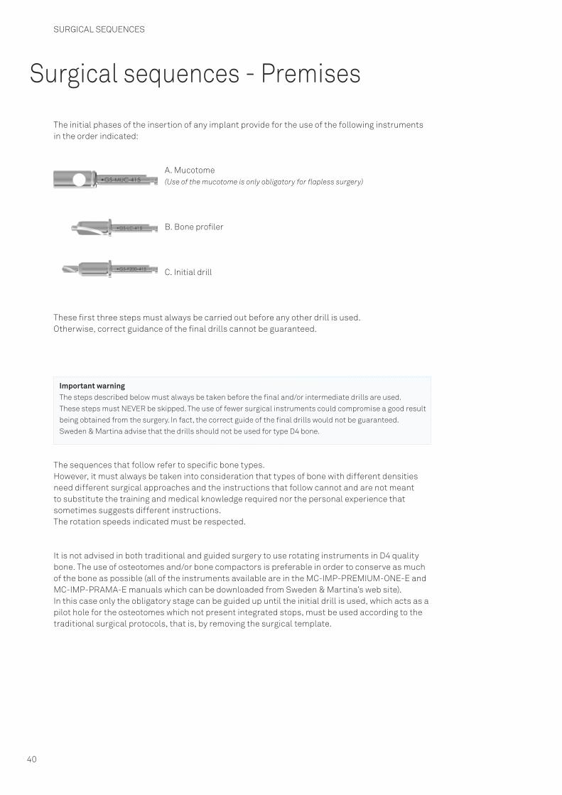
The initial phases of the insertion of any implant provide for the use of the following instruments in the order indicated:
Important warningThe steps described below must always be taken before the final and/or intermediate drills are used.These steps must NEVER be skipped. The use of fewer surgical instruments could compromise a good result being obtained from the surgery. In fact, the correct guide of the final drills would not be guaranteed.Sweden & Martina advise that the drills should not be used for type D4 bone.
The sequences that follow refer to specific bone types. However, it must always be taken into consideration that types of bone with different densities need different surgical approaches and the instructions that follow cannot and are not meant to substitute the training and medical knowledge required nor the personal experience that sometimes suggests different instructions.The rotation speeds indicated must be respected.
It is not advised in both traditional and guided surgery to use rotating instruments in D4 quality bone. The use of osteotomes and/or bone compactors is preferable in order to conserve as much of the bone as possible (all of the instruments available are in the MC-IMP-PREMIUM-ONE-E and MC-IMP-PRAMA-E manuals which can be downloaded from Sweden & Martina’s web site).In this case only the obligatory stage can be guided up until the initial drill is used, which acts as a pilot hole for the osteotomes which not present integrated stops, must be used according to the traditional surgical protocols, that is, by removing the surgical template.
A. Mucotome(Use of the mucotome is only obligatory for flapless surgery)
B. Bone profiler
C. Initial drill
These first three steps must always be carried out before any other drill is used.Otherwise, correct guidance of the final drills cannot be guaranteed.
SURGICAL SEQUENCES
41
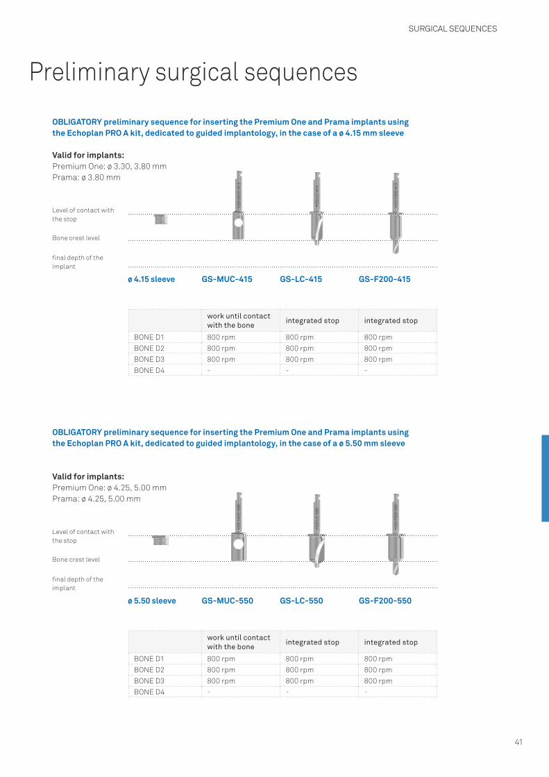
Preliminary surgical sequences
OBLIGATORY preliminary sequence for inserting the Premium One and Prama implants using the Echoplan PRO A kit, dedicated to guided implantology, in the case of a ø 4.15 mm sleeve
OBLIGATORY preliminary sequence for inserting the Premium One and Prama implants using the Echoplan PRO A kit, dedicated to guided implantology, in the case of a ø 5.50 mm sleeve
Valid for implants:Premium One: ø 3.30, 3.80 mmPrama: ø 3.80 mm
Valid for implants:Premium One: ø 4.25, 5.00 mmPrama: ø 4.25, 5.00 mm
work until contact with the bone
integrated stop integrated stop
BONE D1 800 rpm 800 rpm 800 rpmBONE D2 800 rpm 800 rpm 800 rpmBONE D3 800 rpm 800 rpm 800 rpmBONE D4 - - -
work until contact with the bone
integrated stop integrated stop
BONE D1 800 rpm 800 rpm 800 rpmBONE D2 800 rpm 800 rpm 800 rpmBONE D3 800 rpm 800 rpm 800 rpmBONE D4 - - -
Level of contact with the stop
Level of contact with the stop
final depth of the implant
final depth of the implant
Bone crest level
Bone crest level
GS-MUC-415
GS-MUC-550
ø 4.15 sleeve
ø 5.50 sleeve
GS-LC-415
GS-LC-550
GS-F200-415
GS-F200-550
SURGICAL SEQUENCES
42
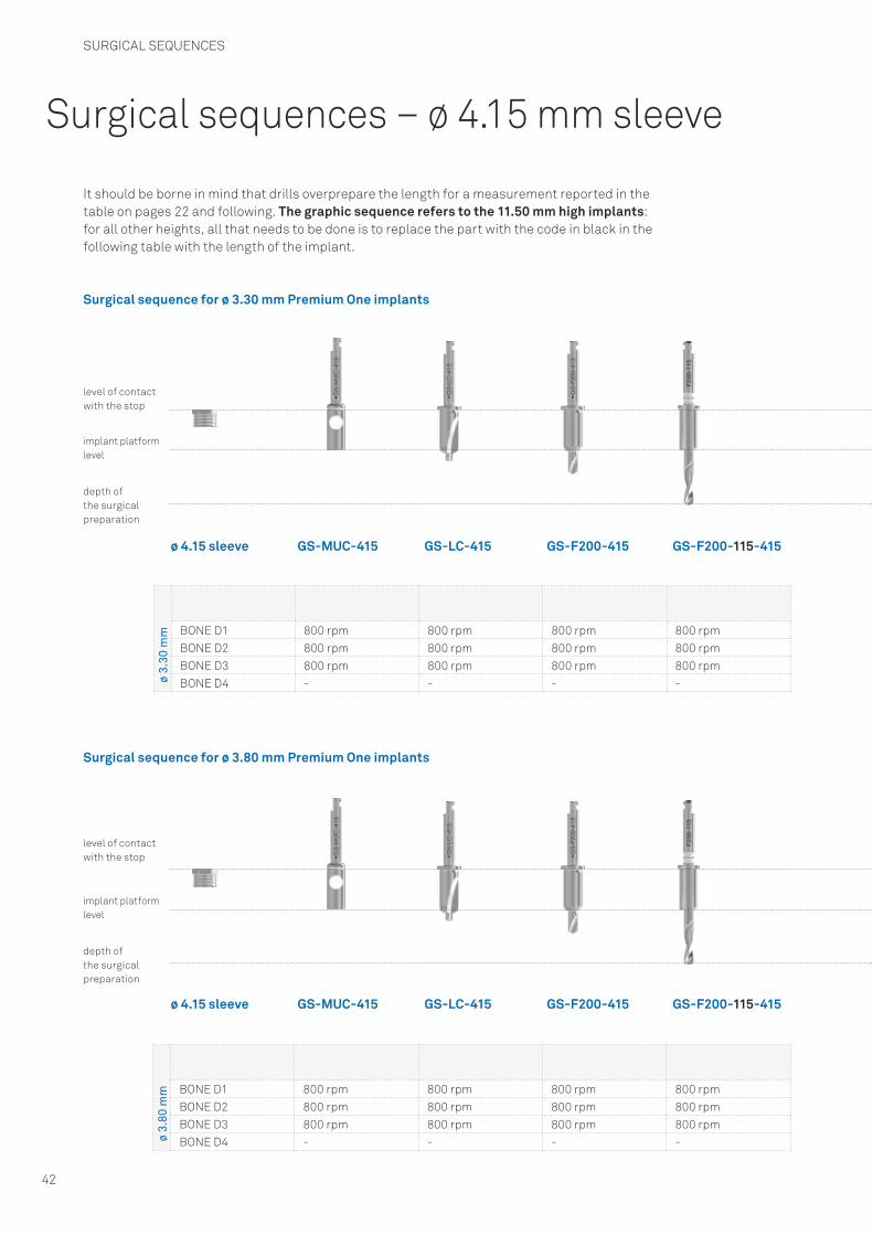
Surgical sequences – ø 4.15 mm sleeve
It should be borne in mind that drills overprepare the length for a measurement reported in the table on pages 22 and following. The graphic sequence refers to the 11.50 mm high implants: for all other heights, all that needs to be done is to replace the part with the code in black in the following table with the length of the implant.
Surgical sequence for ø 3.30 mm Premium One implants
Surgical sequence for ø 3.80 mm Premium One implants
ø 3.
30 m
m BONE D1 800 rpm 800 rpm 800 rpm 800 rpmBONE D2 800 rpm 800 rpm 800 rpm 800 rpmBONE D3 800 rpm 800 rpm 800 rpm 800 rpmBONE D4 - - - -
ø 3.
80 m
m BONE D1 800 rpm 800 rpm 800 rpm 800 rpmBONE D2 800 rpm 800 rpm 800 rpm 800 rpmBONE D3 800 rpm 800 rpm 800 rpm 800 rpmBONE D4 - - - -
implant platform level
implant platform level
level of contact with the stop
level of contact with the stop
depth of the surgical preparation
depth of the surgical preparation
GS-LC-415
GS-LC-415
GS-F200-415
GS-F200-415
GS-F200-115-415
GS-F200-115-415
GS-MUC-415ø 4.15 sleeve
ø 4.15 sleeve GS-MUC-415
SURGICAL SEQUENCES
43
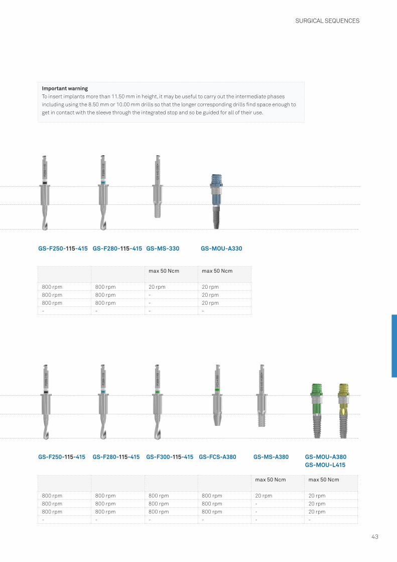
max 50 Ncm max 50 Ncm
800 rpm 800 rpm 20 rpm 20 rpm800 rpm 800 rpm - 20 rpm800 rpm 800 rpm - 20 rpm- - - -
max 50 Ncm max 50 Ncm
800 rpm 800 rpm 800 rpm 800 rpm 20 rpm 20 rpm800 rpm 800 rpm 800 rpm 800 rpm - 20 rpm800 rpm 800 rpm 800 rpm 800 rpm - 20 rpm- - - - - -
GS-F280-115-415
GS-F280-115-415 GS-F300-115-415 GS-FCS-A380
GS-MS-330
GS-MS-A380
GS-MOU-A330
GS-MOU-A380GS-MOU-L415
Surgical sequences – ø 4.15 mm sleeve
GS-F250-115-415
GS-F250-115-415
Important warningTo insert implants more than 11.50 mm in height, it may be useful to carry out the intermediate phases including using the 8.50 mm or 10.00 mm drills so that the longer corresponding drills find space enough to get in contact with the sleeve through the integrated stop and so be guided for all of their use.
SURGICAL SEQUENCES
44
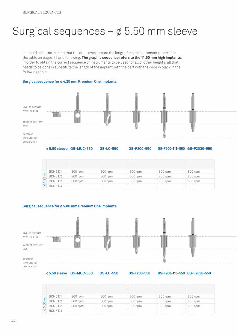
It should be borne in mind that the drills overprepare the length for a measurement reported in the table on pages 22 and following. The graphic sequence refers to the 11.50 mm high implants: in order to obtain the correct sequence of instruments to be used for all of other heights, all that needs to be done is substitute the length of the implant with the part with the code in black in the following table.
Surgical sequence for ø 4.25 mm Premium One implants
Surgical sequence for ø 5.00 mm Premium One implants
ø 4.
25 m
m BONE D1 800 rpm 800 rpm 800 rpm 800 rpm 800 rpmBONE D2 800 rpm 800 rpm 800 rpm 800 rpm 800 rpmBONE D3 800 rpm 800 rpm 800 rpm 800 rpm 800 rpmBONE D4 - - - - -
ø 5.
00 m
m BONE D1 800 rpm 800 rpm 800 rpm 800 rpm 800 rpmBONE D2 800 rpm 800 rpm 800 rpm 800 rpm 800 rpmBONE D3 800 rpm 800 rpm 800 rpm 800 rpm 800 rpmBONE D4 - - - - -
GS-LC-550
GS-LC-550
GS-F200-550
GS-F200-550
GS-F200-115-550
GS-F200-115-550
GS-F2030-550
GS-F2030-550
GS-MUC-550ø 5.50 sleeve
implant platform level
level of contact with the stop
depth of the surgical preparation
implant platform level
level of contact with the stop
depth of the surgical preparation
ø 5.50 sleeve GS-MUC-550
Surgical sequences – ø 5.50 mm sleeve

SURGICAL SEQUENCES
45
Surgical sequences – ø 5.50 mm sleeve
GS-F340-115-550
GS-F340-115-550 GS-F425-115-550
GS-F300-115-550
GS-F300-115-550
GS-MS-A425GS-FCS-A425 GS-MOU-A380SPGS-MOU-L550
max 50 Ncm max 50 Ncm
800 rpm 800 rpm 800 rpm 800 rpm 20 rpm 20 rpm800 rpm 800 rpm 800 rpm 800 rpm - 20 rpm800 rpm 800 rpm 800 rpm 800 rpm - 20 rpm- - - - - -
max 50 Ncm max 50 Ncm
800 rpm 800 rpm 800 rpm 20 rpm 20 rpm800 rpm 800 rpm 800 rpm - 20 rpm800 rpm 800 rpm 800 rpm - 20 rpm- - - - -
GS-FCS-A500 GS-MS-A500 GS-MOU-A380SPGS-MOU-L550
Important warningTo insert implants more than 11.50 mm in height, it may be useful to carry out the intermediate phases including using 8.50 mm or 10.00 mm drills so that the longer corresponding drills have space to use the sleeve with the integrated stop and so be guided for all of their use.
SURGICAL SEQUENCES
46
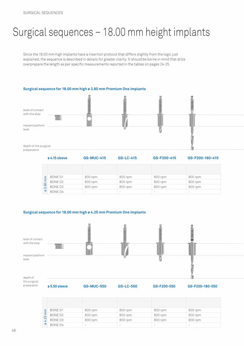
Surgical sequences – 18.00 mm height implants
Since the 18.00 mm high implants have a insertion protocol that differs slightly from the logic just explained, the sequence is described in details for greater clarity. It should be borne in mind that drills overprepare the length as per specific measurements reported in the tables on pages 24-25.
Surgical sequence for 18.00 mm high ø 3.80 mm Premium One implants
Surgical sequence for 18.00 mm high ø 4.25 mm Premium One implants
implant platform level
level of contact with the stop
depth of the surgical preparation
ø 3.
80 m
m BONE D1 800 rpm 800 rpm 800 rpm 800 rpmBONE D2 800 rpm 800 rpm 800 rpm 800 rpmBONE D3 800 rpm 800 rpm 800 rpm 800 rpmBONE D4 - - - -
ø 4.
25 m
m BONE D1 800 rpm 800 rpm 800 rpm 800 rpmBONE D2 800 rpm 800 rpm 800 rpm 800 rpmBONE D3 800 rpm 800 rpm 800 rpm 800 rpmBONE D4 - - - -
GS-LC-415 GS-F200-415 GS-MUC-415ø 4.15 sleeve
ø 5.50 sleeve
GS-F200-180-415
GS-LC-550 GS-F200-550 GS-F200-180-550
implant platform level
level of contact with the stop
depth of the surgical preparation GS-MUC-550
SURGICAL SEQUENCES
47
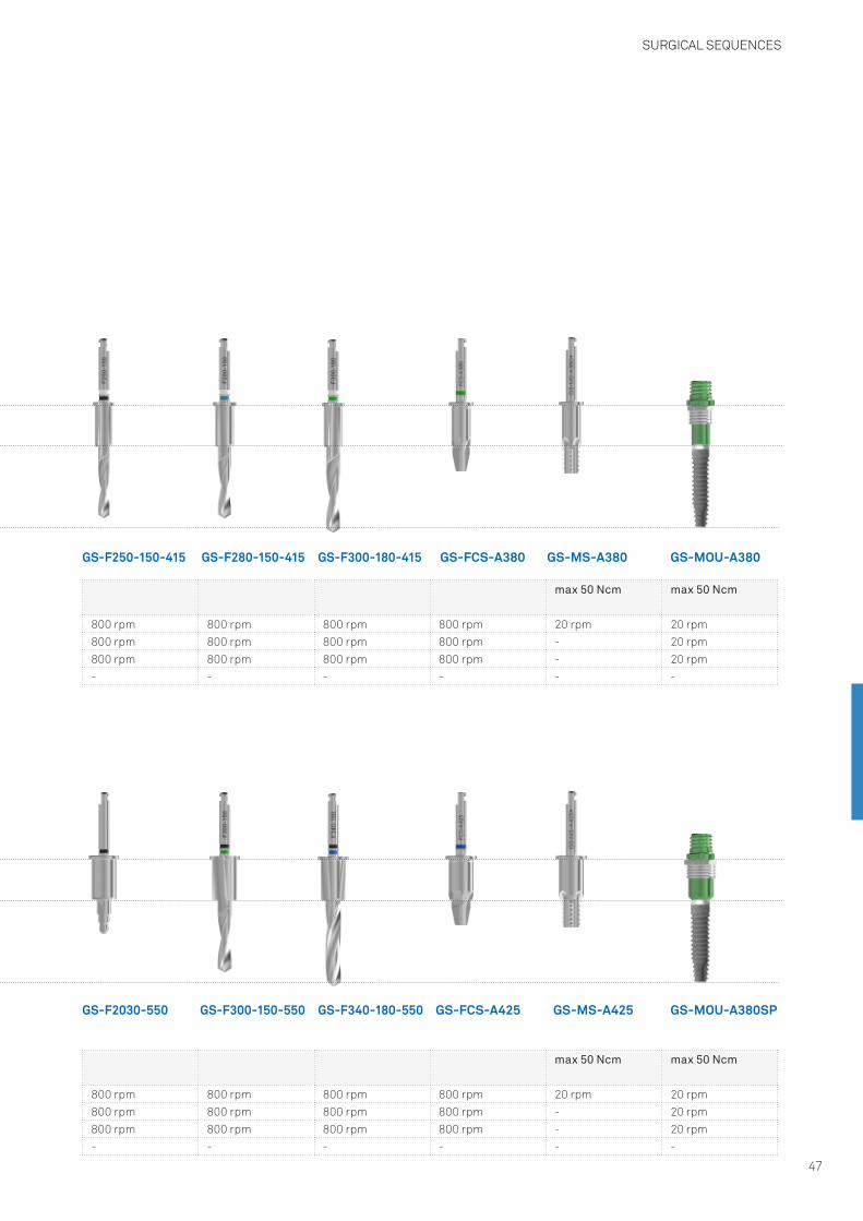
GS-MOU-A380
GS-MOU-A380SP
GS-MS-A380GS-FCS-A380GS-F280-150-415 GS-F300-180-415GS-F250-150-415
max 50 Ncm max 50 Ncm
800 rpm 800 rpm 800 rpm 800 rpm 20 rpm 20 rpm800 rpm 800 rpm 800 rpm 800 rpm - 20 rpm800 rpm 800 rpm 800 rpm 800 rpm - 20 rpm- - - - - -
max 50 Ncm max 50 Ncm
800 rpm 800 rpm 800 rpm 800 rpm 20 rpm 20 rpm800 rpm 800 rpm 800 rpm 800 rpm - 20 rpm800 rpm 800 rpm 800 rpm 800 rpm - 20 rpm- - - - - -
GS-F300-150-550 GS-F340-180-550GS-F2030-550 GS-FCS-A425 GS-MS-A425
SURGICAL PROCEDURES
48
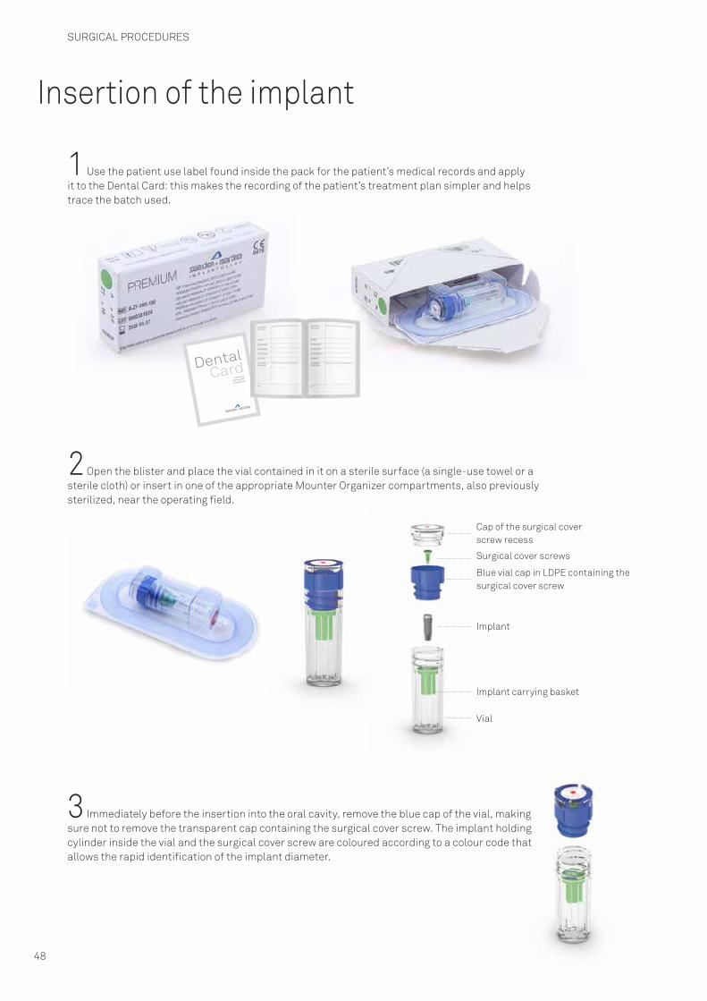
Insertion of the implant
1 Use the patient use label found inside the pack for the patient’s medical records and apply it to the Dental Card: this makes the recording of the patient’s treatment plan simpler and helps trace the batch used.
2 Open the blister and place the vial contained in it on a sterile surface (a single-use towel or a sterile cloth) or insert in one of the appropriate Mounter Organizer compartments, also previously sterilized, near the operating field.
3 Immediately before the insertion into the oral cavity, remove the blue cap of the vial, making sure not to remove the transparent cap containing the surgical cover screw. The implant holding cylinder inside the vial and the surgical cover screw are coloured according to a colour code that allows the rapid identification of the implant diameter.
Cap of the surgical cover screw recess
Surgical cover screws
Blue vial cap in LDPE containing thesurgical cover screw
Implant
Vial
Implant carrying basket
DentalCertificato
di Originalità
e Assistenza
Card

SURGICAL PROCEDURES
49
(A) Open the small vial containing the implant (in the example a Premium One (code A-ZT-380-130) and assemble the mounter (code GS-MOU-A380) on to the implant itself using the appropriate screw (code GS-VTMOU-180, supplied with the mounter) and the screwdriver (code HSM-20-DG).(B) Select the appropriate Easy Insert from those included in the kit and fit it by applying light manual pressure inside the mounter in order to extract the implant from the vial and transport it into the mouth.It should be borne in mind that the implant insertion must be carried out using the torque control so it is always advisable to complete the operation using the torque control ratchet and the Easy Insert with hexagon connection.(C) After the unscrewing of the mounting screw, the mounter can be removed without tilting thanks to the GS-MOU-DG handpiece.
Phase after the implant insertion
Healing timesIt is essential to respect the healing times recommended in implant surgery and periodically verify the progress of the osteointegration with X-rays. Preliminary healing times before loading an implant are influenced by the quality of the receiving bone.Whenever it is decided to defer loading, in order to minimize the discomfort conditioned by respecting the biological time for osteointegration, temporary mobile prostheses must be used prudently, avoiding functional load of these mobile prostheses.
After healing, surgical cover screws are removed from the implants. After this, according to the protocol adopted, tissue profiles are adapted through an appropriate temporary restoration or using suitable healing abutments. It is recommended that healing screws are tightened using a torque of no more than 10 Ncm.
A
C
B
Cleaning, disinfection, sterilization and conservation of the kit and the surgical instruments
Warning! All of the surgical instruments for dental plant and equipment are sold in a non-sterile condition. They must be cleaned, disinfected and sterilized before use by following the procedure validated by Sweden & Martina. These processes must be carried out before first use and before each subsequent re-use. Minimal wear of these devices results from repetition of the processes described in this paragraph.
The correct functioning of the instruments must always be verified before use. Should there be signs of wear, the instruments must be substituted immediately by new devices. In particular, it is recommended that the correct retention of the drivers inside the small engagement wells on the screw heads, which must be selected and screw retained by the screws, is checked.
Non-observation of these instructions may lead to cross-infection and intraoperative complications.
a. CleaningContainers and transports to be used for washing: there are no particular requirements. In the case of automated cleaning: use an ultrasonic tank with an appropriate detergent solution. It is recommended that only neutral detergent is used. The concentration of the solution and the duration of washing must follow the solution manufacturer’s instructions. Use demineralized water to prevent formation of marks and rings. After rinsing, check that all of the residues in the recesses, holes, etc. in the devices have been removed. If necessary, repeat the cycle or use manual cleaning.
In the case of manual cleaning: use a suitable neutral detergent following the manufacturer’s instructions for use. Brush the products using soft bristles under an abundant flow of water. Use the brush to apply the detergent solution on all surfaces.Rinse with distilled water for at least 4 minutes. Make sure that abundant flowing water passes through any holes. In the case of drills with internal irrigation, the suitable pins supplied with the handpieces should be used to guarantee that the irrigation holes have been completely cleaned and are free from residues of bone chips, bone fragments, or biological tissue. After re-rinsing, dry the devices completely using a clean, non shedding wipe with no chemical addives such as alcohol or disinfectant and put them in appropriate sterilization pouch bags. The temperature of any drying cycle carried out as part of the washing machine cycle and disinfection must not exceed 120°C.
b. SterilizationSterilize in vacuum autoclave using the following method:• autoclave (Gravity-Displacement Cycles) at a temperature of 121 °C with minimal exposure of
30 minutes and a drying cycle of 15 minutes.• autoclave (Dynamic-Air-Removal Cycles) at a temperature of 132 °C with minimal exposure of
4 minutes and a drying cycle of 20 minutes.
c. PreservationAfter being sterilized, the product must remain in the pouch bags used for the sterilization. The pouch bags must only be opened immediately before re-use. The sterilization pouch bags are normally able to maintain the sterility inside them unless damaged by the recessed holder. Consequently, be careful not to use components if the pouch bags in which they were preserved have been damaged and re-sterilize them in new pouch bags before re-use. The period of preservation of sterilized products inside the pouch bags must not exceed the pouch bag manufacturer’s recommendation. The product must be preserved in a cool dry place out of direct sunlight and away from water and sources of heat.
SURGICAL PROCEDURES
50

Cleaning, disinfection, sterilization and conservation of the kit and the surgical instruments
Cleaning, disinfection, sterilization and preservation of the CRI5-KIT torque control ratchet
The processes described below must be carried out before the first use and again before each subsequent surgical operation. The repetition of the processes described in this paragraph has minimal wear on the device. Non-observation of these instructions may lead to cross-infection. Containers and transports to be used for washing: there are no particular requirements. As soon as possible after each use of the ratchet, place it in a container filled with a disinfectant/detergent solution and cover both container and ratchet with a cloth. The purpose of the operation is to prevent the drying of contamination agents from the patient, to dissolve them and then facilitate cleaning and make it more effective. Fully dismantle the ratchet by following these instructions:
Completely unscrew the torque- adjusting screw and extract the spring contained inside the handle of the ratchet’s body. Do not separate the spring from the pin that acts as the stop.
Use the hexagonal point at the base of the torque-adjusting screw to completely unscrew and extract the fixation screws of the cover on the side labelled OUT. Exert light pressure so that damage to the hexagonal point is avoided.
After having removed the cover, extract the two components contained inside the ratchet head: the toothed wheel pawl and the wheel tooth stop.
In the case of manual cleaning, mechanically clean all of the instrument’s internal and external surfaces under hot water using a soft bristled brush. Rinse the holes in the head that are difficult to access and around the wheel pawl and the wheel tooth stop by injecting hot water from a syringe without a needle. If necessary, proceed likewise for the inside of the handle and the torque adjustment device. Use a suitable neutral detergent following the manufacturer’s instructions for use. Use the brush to apply the detergent solution on all surfaces. Rinse with distilled water for at least 4 minutes. Make sure flowing water passes through the passageways in abundance. In the case of automated ultrasonic cleaning: use an ultrasonic tank and a suitable detergent solution.It is recommended that only neutral detergent is used. The concentration of the solution and the duration of washing must follow the solution manufacturer’s instructions. Use demineralized water to prevent formation of marks and rings. Avoid contact between the parts during this cycle because this causes the surfaces worked to deteriorate and consequently the torque measurements to be less precise. After rinsing, check that all of the residues in the recesses, holes, etc. in the devices have been removed. If necessary, repeat the cycle or use manual cleaning.Observation: residual blood or other deposits reduce the sterilization’s effectiveness which is why it is important to effect precise cleaning. Avoid liquid spurting or splashing during all cleaning cycles and work with appropriate protection from spurting and splashing. Avoid contact between this instrument and other nickel-plated instruments.
The parts are re-assembled before proceeding to sterilization. Dry the parts and lubricate the functional areas moderately and reassemble the ratchet as indicated in the figure below.Too much lubricant causes it to rise to the instrument’s surface during sterilization. Only use the lubricant supplied.
SURGICAL PROCEDURES
51

After having lubricated the parts indicated in the figure, insert the two elements that compose the ratchet head in the following sequence: toothed wheel pawl and then the wheel tooth stop.
Once parts 2 and 3 has been lubricated and inserted in the head of the ratchet body, position the cover and roll the ratchet body from the OUT side. Tighten the screw using the hexagonal tip of the torque-adjusting screw.
Lubricate the spring inside the ratchet’s handle as shown in the figure. Assemble the torque-adjusting screw checking that the instrument works correctly and manually activate the wheel pawl.
Lubricate the areas of contact between the tooth of the wheel pawl and the stump pin of the wheel tooth stop.
Sterilization: in vacuum autoclave using the following method:• autoclave (Gravity-Displacement Cycles) at a temperature of 121°C with minimal exposure of 30
minutes and a drying cycle of 15 minutes.• autoclave (Dynamic-Air-Removal Cycles) at a temperature of 132°C with minimal exposure of 4
minutes and a drying cycle of 20 minutes.
This procedure is important in maintaining the instrument’s accuracy within a tolerance of ± 3.5 Ncm. Activate the torque control and insertion mechanism to verify correct functioning. Remove any traces of lubricant from the ratchet’s external surfaces. Place the device in appropriate sterilization pouch bags. It is advisable to follow the instructions during the disassembly and re-assembly operations.
SURGICAL PROCEDURES
52

Cleaning, disinfection, sterilization and preservation of the TWL torque control ratchet
The processes described below must be carried out before the first use and before each subsequent surgical operation. The repetition of the processes described in this paragraph has minimal wear on the device. Non-observation of these instructions may lead to cross-infection.
a. CleaningContainers and transports to be used for washing: there are no particular requirements. As soon as possible after each use of the ratchet, place it in a container filled with a disinfectant/detergent solution and cover both container and ratchet with a cloth.The purpose of this operation is to prevent the drying of contamination agents from the patient, to dissolve them and then facilitate cleaning and make it more effective.
Fully dismantle the ratchet by following these instructions:
Press the hand driver and take it out from the ratchet’s head, then remove the head by pressing Inside the socket, taking it out very carefully. The three parts separated are ready for cleaning.
In the case of automated cleaning using ultrasound: use an ultrasonic tank and a suitable detergent solution. It is recommended that only neutral detergent is used.The concentration of the solution and the duration of washing must follow the solution manufacturer’s instructions. Use demineralized water to prevent the formation of marks and rings. Avoid contact between the parts during this cycle because this causes the surfaces worked to deteriorate and consequently the torque measurements to be less precise.
Immediately after rinsing, check that all of the residues in the recesses, holes, etc. in the devices have been removed. If necessary, repeat the cycle or manual cleaning. Observation: residual blood or other deposits reduce the sterilization’s effectiveness which is why it is important to effect precise cleaning. Avoid liquid spurting or splashing during all cleaning cycles and work with appropriate protection from spurting and splashing. Avoid contact between this instrument and other nickel-plated instruments.
The parts are re-assembled before proceeding to sterilization.
SURGICAL PROCEDURES
53

This procedure is important in maintaining the instrument’s accuracy within the following tolerances:
10 Ncm ± 0,75 Ncm
30 Ncm ± 1,5 Ncm
50 Ncm ± 2,5 Ncm
70 Ncm ± 3,5 Ncm
90 Ncm ± 4,5 Ncm
After cleaning, connect the ratchet’s head to the body, pushing the components together and rotating them in the opposite direction until you hear the terminal spring closing.
Push the hand driver into the ratchet until you hear the terminal spring closing. The arrow on the ratchet’s head indicates the direction of functioning.
Place the device in appropriate sterilization pouch bags. It is advisable to follow the instructions in this manual during the disassembly and re-assembly operations.
b. SterilizationSterilize in vacuum autoclave using the following method:• autoclave (Gravity-Displacement Cycles) at a temperature of 121°C with minimal exposure of 30
minutes and a drying cycle of 15 minutes.• autoclave (Dynamic-Air-Removal Cycles) at a temperature of 132°C with minimal exposure of 4
minutes and a drying cycle of 20 minutes.
c. PreservationAfter being sterilized, the product must remain in the pouch bags used for the sterilization.The pouch bags must only be opened immediately before re-use. The sterilization pouch bags are normally able to maintain the sterility inside them unless damaged by the recessed holder. Consequently, be careful not to use components if the pouch bags in which they were preserved have been damaged and re-sterilize them in new pouch bags before re-use.The period of preservation of sterilized products inside the pouch bags must not exceed the pouch bag manufacturer’s recommendation.The product must be preserved in a cool dry place out of direct sunlight and away from water and sources of heat.
SURGICAL PROCEDURES
54

Composition of the materials
The materials used to manufacture the devices illustrated in this manual were selected on the basis of the properties specified in order for their intended use to conform to directive 93/42, assimilated in Italy as law 46/97, Attachment I Essential Requirements, subsection 7.1 and to conform to EU Medical Devices Regulation 2017/745.
ImplantsThe implants are made of commercially pure 4 Gr. titanium in conformity with harmonized European standards. Allergic reaction to titanium is rare but possible. Consequently, preventively verifying with the patients that they do not have an allergy of this type is always necessary. The specifications of the 4 Gr. titanium used are shown below.
4 Gr.* titanium (Cold worked)* ASTM F67-13(2017), ISO 5832-2: 2018
*This technical information is faithful to all that is expressly specified in the regulations in force for the use of 4 Gr. titanium in implantology:• ASTM F67-13(2017): Standard Specification for unalloyed titanium, for surgical implant
applications.• ISO 5832-2: 2018: Implant for surgery - Metallic materials - Part 2: Unalloyed titanium.
N.B.: Using cold worked 4 Gr. titanium to manufacture Sweden & Martina implants means that mechanical specifications superior to those prescribed can be exploited. Furthermore, the excellent results documented during decades of clinical experience support the choice of the cold worked manufacturing process and ZirTi surface treatment that expresses and enhances the potential of the raw materials selected by Sweden & Martina.
Surgical instrumentsThe surgical instruments are manufactured in the following materials as a function of the type of component:• 5 Gr. titanium• 1.4197 steel • 1.4542 steel • 1.4305 steel (AISI 630)• 1.4108 steel (AISI 303)• 1.4108 steel • 1.4112 steel
It is recommended that any allergy to the raw materials is checked with the patient.
chemical composition maximum permitted values (%) tolerance
nitrogen 0.05 +/- 0.02
carbon 0.10 +/- 0.02
hydrogen 0.015 +/- 0.002
iron 0.25 +/- 0.10 (%<0.25)+/- 0.15 (%>0.25)
oxygen 0.20 +/- 0.02 (%<0.20)+/- 0.03 (%>0.20)
titanium remainder -
GENERAL INFORMATION
55
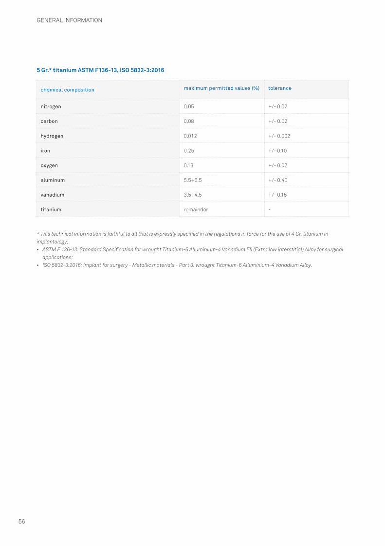
GENERAL INFORMATION
56
* This technical information is faithful to all that is expressly specified in the regulations in force for the use of 4 Gr. titanium in implantology:• ASTM F 136-13: Standard Specification for wrought Titanium-6 Alluminium-4 Vanadium Eli (Extra low interstitial) Alloy for surgical
applications;• ISO 5832-3:2016: Implant for surgery - Metallic materials - Part 3: wrought Titanium-6 Alluminium-4 Vanadium Alloy.
chemical composition maximum permitted values (%) tolerance
nitrogen 0.05 +/- 0.02
carbon 0.08 +/- 0.02
hydrogen 0.012 +/- 0.002
iron 0.25 +/- 0.10
oxygen 0.13 +/- 0.02
aluminum 5.5÷6.5 +/- 0.40
vanadium 3.5÷4.5 +/- 0.15
titanium remainder -
5 Gr.* titanium ASTM F136-13, ISO 5832-3:2016

GENERAL INFORMATION
57
Key to the symbols on the implant pack:
Key to the symbols on the surgical instruments pack:
description symbol
Warning! See instructions for use
Batch number
Code
Manufacturer
Consult the instructions for use
CE Marking for class IIa and IIb products
0476
0476American federal law limits the sale of this device to or by order of professional practitioners
Do not re-sterilize
Do not reuse, single use product
Never use if the pack is damaged
Sterilized by ionizing radiation
Expiration date after which do not use the product
description symbol
Warning! See instructions for use
Batch number
Code
Manufacturer
Consult the instructions for use
CE Marking for class IIa and IIb products
0476
0476Marcatura di conformità CE per i prodotti di classe I
American federal law limits the sale of this device to or by order of professional practitioners
Non-sterile product

GENERAL INFORMATION
58
Key to the symbols on the implant pack:
THE LAST REVISION DATE OF THIS MANUAL IS JULY 2018.
The development and manufacture of the device described in this manual was carried out in conformity with the latest EU directives and harmonized regulations governing the materials used, the production processes, sterilization, information provided and packaging.
description symbol
Warning! See instructions for use
Batch number
Code
Manufacturer
Consult the instructions for use
CE Marking for class IIa and IIb products
0476
0476CE Marking for class I products
American federal law limits the sale of this device to or by order of professional practitioners
Do not reuse, single use product
Non-sterile product


rev.07-18v.01
The implants, standard prosthetic components and surgical instruments contained in this catalogue are Medical devices and are manufactured by Sweden & Martina S.p.A. They conform to the ISO 9001 and ISO 13485 standards and are certified with the CE Mark (Class I) and CE 0476 mark (Class IIA and class IIB) in compliance with Regulation (EU) Medical Devices n. 2017/745.
The Sweden & Martina plant manufactures Medical Devices in compliance with the CGMPs in force in the USA and in other countries worldwide.
Some products may not be regulatory/released for sale in all markets.All trademarks herein are the property of Sweden & Martina S.p.A. unless otherwise indicated.This material is intended for laboratories and clinicians and is not intended for patient distribution.This material is not to be redistributed, duplicated, or disclosed without the express written consent of Sweden & Martina S.p.A.For additional product information, including indications, contraindications, warnings, precautions, and potential adverse effects, see Sweden & Martina S.p.A. website.
The contents are updated at the time of publication. Check with the company for any subsequent updates.
MC-UD-EPLAN
PROA-E
Sweden & Martina LtdUnit 45 Basepoint Business Centre Metcalf Way, Crawley,West Sussex, RH11 7XX, UK Toll free 0800 [email protected]
Sweden & Martina S.p.A.Via Veneto, 1035020 Due Carrare (PD), ItalyTel. +39.049.9124300Fax [email protected]
www.sweden-martina.com
Sweden & Martina Mediterranea S.L. - Españ[email protected] & Martina Lda - [email protected]
Sweden & Martina Inc. Distributor for U.S.80 Broad Street, 5th floor, Suite 502New York, NY 10004Toll free 1-844-8MARTINA (1-844-862-7846)[email protected]
www.sweden-martinainc.com