surface roughness measuring system surftest...
TRANSCRIPT
Small Tool Instruments andData Management
Test Equipment andSeismometers
Digital Scale and DRO Systems
Coordinate Measuring Machines
Sensor Systems
Optical Measuring
Form Measurement
Vision Measuring Systems
Form Measurement
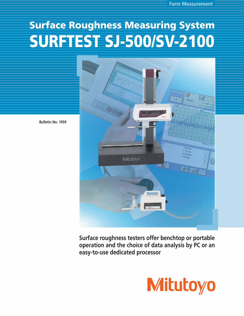
Surface roughness testers offer benchtop or portable operation and the choice of data analysis by PC or an easy-to-use dedicated processor
SURFTEST SJ-500/SV-2100Surface Roughness Measuring System
Bulletin No. 1959

2
Surftest SJ-500/SV-2100Dedicated data processor type
Improved operability
7.5 Color TFT LCDThe dedicated data processor has a high-visibility 7.5" color TFT LCD. Icon display and touch panel operation provide user-friendly display and easy operation.Positioning by joystick and manual control knobs on the processorEasy-to-operate joystick. Fine positioning of stylus required for small-hole measurements can be easily performed using the manual fine-adjustment knobs.Multiple trace functionA machine can be programmed to take up to three traces, one after the other.Auto leveling table (optional)Automatically levels the surface to be tested for easy, strain-free setup.
Various types of analysisCapable of fine-contour analysisSupports 43 types of analysis parameters, complying with surface roughness standards such as ISO 1997 and JIS 2001. Also capable of various fine-contour analysis. * Contour analyses: Area, circle, angle, coordinate difference, step, inclination
High-durabilityCeramic guidewayA ceramic guideway, inherently free from wear and deterioration with age, is employed to maintain the traversing straightness of the drive unit (X-axis) indefinitely. Maintenance-free design, since anti-corrosion treatment is not required for ceramic.
SJ-500Traverse: 1.97" (50mm)Compact, high-performance type
SV-2100M4Traverse: 3.94" (100mm)Manual column type
SV-2100S4/H4/W4Traverse: 3.94" (100mm)Power column type
Dedicated data processorAdvanced processing and easy operation

3
High-visibility color display panel
A high-visibility 7.5" color TFT LCD, color icon display and touch-operated panel provide user-friendly, easy operation.Built-in thermal printer. Fine contour analysis provided as standard.
Supports 16 languagesJapanese, English, German, French, Italian, Spanish, Portuguese, Korean, Simplified Chinese, Traditional Chinese, Czech, Polish, Hungarian, Turkish, Swedish, Dutch
Multiple trace programming function
A machine can be programmed to take up to three consecutive traces by one-key operation, as shown in the figure below.
•SJ-500/SV-2100M4Consecutive tracing in X-axis direction only
•SV-2100S4/H4/W4X-axis tracing with programmed Z-axis shifts possible
Measurement
Traverse
Example: SV-2100S4 input screen
Efficient positioning by joystick and adjustment knobs
Both a fast-traverse joystick (X-axis: .78"/s (20mm/s) for SJ-500, 1.98"/s (40mm/s) for SV-2100, Z2-axis: .78"/s (20mm/s) for SV-2100S4/H4/W4) and manual fine-adjustment knobs, essential for positioning in small hole measurement, are standard features.
Navigation function aids leveling
When using an optional 3-axis adjustment table or leveling table, a navigation screen is available to help the operator level the surface to be tested.
Positioning in small hole measurement
Positioning in Y/Z-directions with column fine-adjustment knob (or detector elevation knob) and optional cross-travel table.
Positioning at the trace start point with X-axis fine-adjustment knob.
Powerful support for leveling adjustments
Example of 3-axis adjustable table
The user is guided through the leveling procedure to determine the amount of adjustment needed.
Easy operation, high-accuracy analysis of surface roughness and fine contours!
4
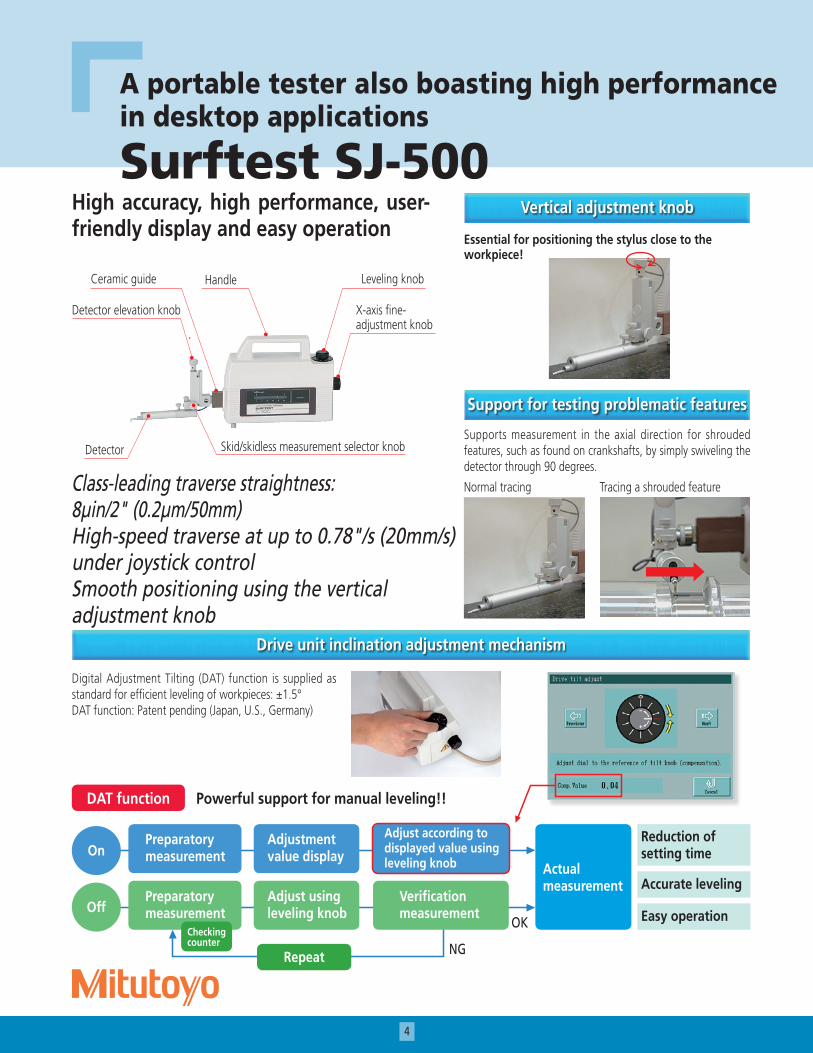
Surftest SJ-500
A portable tester also boasting high performance in desktop applications
High accuracy, high performance, user-friendly display and easy operation
Class-leading traverse straightness: 8µin/2" (0.2µm/50mm)High-speed traverse at up to 0.78"/s (20mm/s) under joystick controlSmooth positioning using the vertical adjustment knob
Vertical adjustment knob
Essential for positioning the stylus close to the workpiece!
Support for testing problematic features
Supports measurement in the axial direction for shrouded features, such as found on crankshafts, by simply swiveling the detector through 90 degrees.
Normal tracing Tracing a shrouded feature
Drive unit inclination adjustment mechanism
Digital Adjustment Tilting (DAT) function is supplied as standard for efficient leveling of workpieces: ±1.5°DAT function: Patent pending (Japan, U.S., Germany)
Detector
Detector elevation knob
Ceramic guide Handle Leveling knob
X-axis fine-adjustment knob
Skid/skidless measurement selector knob
DAT function Powerful support for manual leveling!!
OnPreparatory measurement
Adjustment value display
Adjust according to displayed value using leveling knob
OffPreparatory measurement
Adjust using leveling knob
Verification measurement
Checking counter
Reduction of setting time
Accurate leveling
Easy operation
Repeat
OK
NG
Actual measurement
5
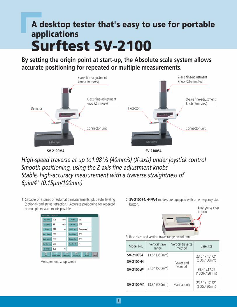
Surftest SV-2100
A desktop tester that's easy to use for portable applications
High-speed traverse at up to1.98"/s (40mm/s) (X-axis) under joystick controlSmooth positioning, using the Z-axis fine-adjustment knobsStable, high-accuracy measurement with a traverse straightness of 6µin/4" (0.15µm/100mm)
By setting the origin point at start-up, the Absolute scale system allows accurate positioning for repeated or multiple measurements.
Z-axis fine-adjustment knob (1mm/rev)
X-axis fine-adjustment knob (2mm/rev)
Connector unit
Detector
Z-axis fine-adjustment knob (0.67mm/rev)
X-axis fine-adjustment knob (2mm/rev)
Detector
Connector unit
1. Capable of a series of automatic measurements, plus auto leveling (optional) and stylus retraction. Accurate positioning for repeated or multiple measurements possible.
Measurement setup screen
2. SV-2100S4/H4/W4 models are equipped with an emergency stop button.
3. Base sizes and vertical travel range on column
Model No. Vertical travel range
Vertical traverse method Base size
SV-2100S4 13.8" (350mm)
Power and manual
23.6" x 17.72"(600×450mm)SV-2100H4
21.6" (550mm)SV-2100W4 39.4" x17.72 (1000×450mm)
SV-2100M4 13.8" (350mm) Manual only 23.6" x 17.72"(600×450mm)
Emergency stop button
SV-2100M4 SV-2100S4
6
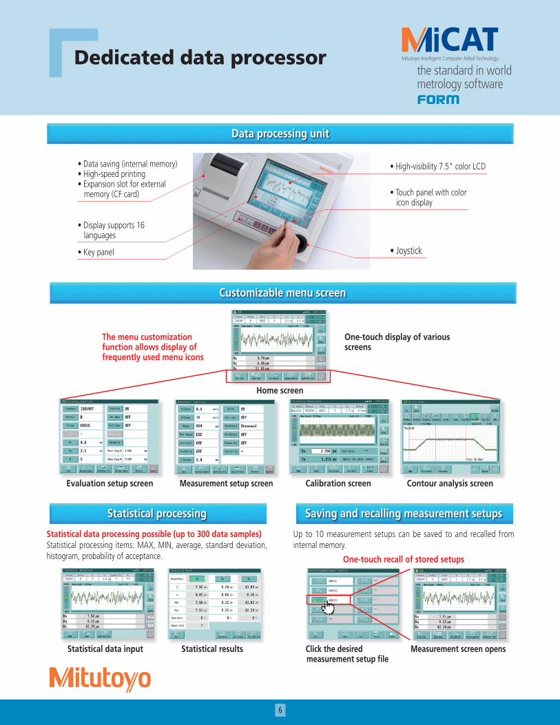
Dedicated data processor
Data processing unit
• Data saving (internal memory)• High-speed printing• Expansion slot for external memory (CF card)
• Display supports 16 languages
• Key panel
• High-visibility 7.5" color LCD
• Touch panel with color icon display
• Joystick
Customizable menu screen
The menu customization function allows display of frequently used menu icons
One-touch display of various screens
Evaluation setup screen Measurement setup screen Calibration screen Contour analysis screen
Home screen
Statistical processing
Statistical data processing possible (up to 300 data samples)Statistical processing items: MAX, MIN, average, standard deviation, histogram, probability of acceptance.
Saving and recalling measurement setups
Up to 10 measurement setups can be saved to and recalled from internal memory.
One-touch recall of stored setups
Statistical data input Statistical results Click the desired measurement setup file
Measurement screen opens
7
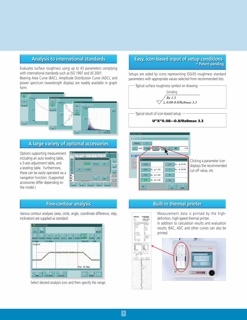
Analysis to international standards
Evaluates surface roughness using up to 43 parameters complying with international standards such as ISO 1997 and JIS 2001.Bearing Area Curve (BAC), Amplitude Distribution Curve (ADC), and power spectrum (wavelength display) are readily available in graph form.
Easy, icon-based input of setup conditions* Patent pending
Setups are aided by icons representing ISO/JIS roughness standard parameters with appropriate values selected from recommended lists.
A large variety of optional accessories
Options supporting measurement including an auto leveling table, a 3-axis adjustment table, and a leveling table. Furthermore, these can be easily operated via a navigation function. (Supported accessories differ depending on the model.)
Fine-contour analysis
Various contour analyses (area, circle, angle, coordinate difference, step, inclination) are supplied as standard.
Select desired analysis icon and then specify the range.
Typical surface roughness symbol on drawing
Grinding
Ra 1.5 0.08-0.8/Rz8max 3.3
Typical result of icon-based setup
U”X”0.08—0.8/Rz8max 3.3
Built-in thermal printer
Measurement data is printed by the high-definition, high-speed thermal printer.In addition to calculation results and evaluation results, BAC, ADC and other curves can also be printed.
Clicking a parameter icon displays the recommended cut-off value, etc.

8
PC data processing type
A superior data processing tester with PC data analysis for higher efficiency.* If a power column type with PC data-processing is desired, consider the SV-3100 series
SJ-500P
SURFPAK-EZ: Easy-to-use task-focused software
User-friendly graphical display and button layout allows intuitive operation. Simplified fine-contour analysis provided as standard, including step, area, angle, and circle calculation.
Measurement and results display screen Calibration and control screen (SJ-500P) Simplified contour analysis screen
Surftest SJ-500P

9
Specifications
Surftest SJ-500PSpecificationsType of data processing Dedicated data processor PC systemModel No. SJ-500 SV-2100M4 SV-2100S4 SV-2100H4 SV-2100W4 SJ-500P
Order No.*
with 0.75 mN detector 178-533-01A 178-637-01A 178-681-01A 178-683-01A 178-685-01A 178-531-01A
with 4 mN detector 178-533-02A — — — — —
Travel range (operation)
X axis 2" (50mm ) (power drive/manual) 3.94" (100mm) (power drive / manual) 2" (50mm)
(power drive / manual)Z2 axis (column) –––––– 350mm (manual) 13.8" (350mm) (power drive / manual) ––––––
Measuring range
X axis 2" (50mm) 3.94" (100mm) 2" (50mm)Z1 axis (detector unit) 3200µin / 3200µin / 320µin (800µm / 80µm / 8µm)
ResolutionX axis 1.97µin (0.05µm)Z1 axis (detector unit) 0.4µin / 3200µin range, 0.4µin / 3200µin range, 0.004µin /320µin range (0.01µm / 800µm range, 0.001µm / 80µm range, 0.0001µm / 8µm range) Z2 axis (column) –––––– –––––– (1µm) ––––––
Power drive speed
X axis 0 - 0.78"/s 0 - 20mm/s (via joystick) 0 - 1.98"/s (0 - 40mm/s) (via joystick) 0 - 20mm/s
(via PC)Z2 axis (column) –––––– –––––– 0 - 0.78"/s (0 - 20mm/s) (via joystick) ––––––
Measuring speed 0.00078" - 0.2"/s (0.02 - 5mm/s)Traverse guideway straightness 8 µin / 2"(0.2µm / 50mm) 6µin / 4" (0.15µm / 100mm) 8µin / 2"(0.2µm / 50mm)Stylus up/down operation Arc movementPoint of stylus Downward
DetectorMeasuring force 0.75 mN or 4 mNStylus tip 0.75mN detector: 60°, R2 µm or 4mN detector: 90°, R5µm
Applicable standards JIS’82 / JIS’94 / JIS’01 / ISO’97 / ANSI / VDA
Assessed profiles
Dedicated data processor type: P (primary profile), R (roughness profile), WC, envelope residual profile, roughness motif, waviness motifPC system type: P (primary profile), R (roughness profile), WC, WCA, WE, WEA, DIN4776 profile, E (envelope residual profile), roughness motif, waviness motif
Evaluation parameters
Dedicated data processor type: Ra, Rc, Ry, Rz, Rq, Rt, Rmax, Rp, Rv, R3z, Sm, S, Pc, mr (c),δc, mr, tp, Htp, Lo, lr, Ppi, HSC, Δa, Δq, Ku, Sk, Rpk, Rvk, Rk, Mr1, Mr2, A1, A2, Vo, λa, λq, R, AR, Rx, W, AW, Wx, Wte, (43 parameters), CustomizationPC system type: Pa, Pq, Psk, Pku, Pp, Pv, Pz, Pt, Pc, PSm, PΔq, Pmr (c), Pmr, Pδc, Ra, Rq, Rsk, Rku, Rp, Rv, Rz, Rt, Rc, RSm, RΔq, Rmr (c), Rmr, Rδc, Wa, Wq, Wsk, Wku, Wp, Wv, Wz, Wt, Wc, WSm, WΔq, Wmr (c), Wmr, Wδc, Rk, Rpk, Rvk, Mr1, Mr2, A1, A2, Rx, AR, R, Wx, AW, W, Wte, Ry, RyDIN, RzDIN, R3y, R3z, S, HSC, Lo, lr, Δa, λa, λq, Vo, Htp, NR, NCRX, CPM, SR, SAR, NW, SW, SAW
Analysis graphsDedicated data processor type: ADC, BAC, power spectrum graphPC system type: ADC, BAC Graph, power spectrum graph, auto-correlation graph, Walsh power spectrum graph, Walsh auto- correlation graph, slope distribution graph, local peak distribution graph, parameter distribution graph
Curved surface compensation
Dedicated data processor type: Parabolic compensation, Hyperbolic compensation, Elliptical compensation, Circular compensation Conic compensation, Inclination (Entire, Arbitrary)PC system type: Parabolic compensation, Hyperbolic compensation, Elliptical compensation, Circular compensation, Conic compensation, Inclination (Entire, Arbitrary), Polynomial compensation
Contour analysis Dedicated data processor type: Area, Circle, Angle, Coordinate difference, Step, InclinationPC system type (SURFPAK-EZ): Area, Circle, Angle, Coordinate difference, Step, Inclination
Filters Dedicated data processor type: 2CR-75%, 2CRPC-75%, Gaussian, Robust-splinePC system type: 2CR-75%, 2CR-50%, 2CRPC-75%, 2CRPC-50%, Gaussian, Rubust-spline
Base size (width x depth) –––––– 23.6" x 17.7"(600x450mm) 39.4"x17.7"(1000x450mm) ––––––Base material –––––– Granite ––––––
External dimensions (W x D x H)
Main unit 16.7"x3.7"x6.3"(425x94x160mm)
28.2"x17.7"x34"(716x450x863mm)
30.16"x17.7"x38"(766x450x966mm)
30.16"x17.7"x45.9"(766x450x1166mm)
45.9"x17.7"x46.3"(1166x450x1176mm)
16.7"x3.7x63"(425x94x160mm)
Display unit 12.9" x 10.63" x 4.38 (330x270x124mm) ––––––Electronic unit –––––– –––––– 14.6" x 9.65" x 2.83" (372x245x71.8mm) ––––––
PC I/F unit –––––– –––––– –––––– –––––– –––––– 13.7" x 10.4" x 3.4"350x263x86mm
MassMain unit 5.9 lbs (2.7kg) 308.6 lbs (140kg) 308.6 lbs (140kg) 330.7 lbs (150kg) 485 lbs (220kg) 5.91 lbs (2.7kg)Display unit 8.8 lbs (4.0kg) ––––––Electronic unit –––––– –––––– 6.6 lbs (3.0kg) ––––––

10
Dedicated data processor Electronic unitSJ-500
SV-2100M4 SV-2100S4 / SV-2100H4
SV-2100W4
Only for SV-2100S4 / H4 / W4
81.816
09417.520310~6062.5
.9
0
.8.7
.6
.5
.4
.3 .2
.1+ -
270
330 124 320
69.5
71.8
245
372
966(
1166)
854(
1054)
80
85
35
450600
100
12 130175
258 100
350(
550)
116716
550
1116
116 175 1301211
0
1000
450
35
85
80
1176
1054
658 100
716116
863 75
1
350
100258
175 1301210
0
600
450
35
85
80
Dimensions
Measuring range
T-groove dimensions (common to all types)
8
15
14
7
Unit: mm
( ): SV-2100H4

11
Optional Accessories
Manual column stand: 178-085 (for SJ-500)
Suitable for desktop use in inspection rooms and such.
DAT leveling table: 178-048
This table can be used by itself or in conjunction with other leveling tables.
No.178-085 * Except measuring unitVertical adjustment range: 11.8" (300mm)Dimension (W × D × H): 23.6" x 17.7" x 28" (600 × 450 × 710mm)Weight: 242 lbs (110kg)
Auto-leveling table: 178-081 (for SJ-500 / SV-2100M4), 178-083 (for SV-2100S4 / H4 / W4)
This is a stage that performs fully automatic leveling as measurement starts, freeing the user from this tedious operation. Fully automatic leveling can be done quickly by anyone. In addition, the operation is easy and reliable.
Inclination adjustment angle ±2°
Maximum load 15.4 lbs (7kg)
Table dimensions 5.12" x 3.94"(130x100mm)
Mass 7.7lbs (3.5kg)
Inclination adjustment angle ±1.5°
Maximum load 15.4 lbs (7kg )
Table dimensions 5.12" x 3.94" (130x100mm)
Leveling table: 178-043-1 (with analog heads) 178-042-1 (with digital heads)
No.178-043-1
Order No. 178-043-1 178-042-1Table dimensions 5.12" x 3.94" (130x100mm)Maximum load 33 lbs (15kg)Inclination adjustmnt. angle ±1.5°Swiveling angle ±3°X/Y-axis travel range ±0.49" (±12.5mm)Resolution 0.01mm 0.001mm
Dimensions 8.66" x 7.4" x 3.27"(220×189×83mm)
10.3" x 9.17 x 3.27"(262×233×83mm)
Mass 13.2 lbs (6Kg) 13.9 lbs (6.3Kg)
No.178-042-1
Quick chuck: 211-032 Micro-chuck: 211-031This chuck is useful when measuring small workpieces. The knurled ring makes clamping very easy. This chuck is suitable for clamping extra-small diameter workpieces
(ø1mm or less), which cannot be clamped with the centering chuck.
5030
0710
1210
059
8
600
198.7 50
Measuring range
T-groove
8
15
11.8
7
Dimensions of SJ-500 with manual column stand Unit: mm
Retention range
Inner latch OD: ø 0.039" - 1.42"(1 - 36mm)Inner latch ID: ø 0.55" - 2.76" (14 - ø70m)Outer latch OD: ø 0.039 - 2.95" (1 - ø75mm)
Dimensions ø 4.64 x 1.61" (118x41mm)Mass 2.65 lbs (1.2kg)
Clamping range OD: ø 0 - 0.06" (0 - 1.5mm)
Dimensions ø 4.64" – 1.91" (118x48.5mm)
Mass 1.32 lbs (0.6kg)
12
178-024:Stand
178-023:Vibration isolator
178-025:Vibration isolator
218-001 (mm), 218-011 (inch):Cross-travel table
218-002:Table
12AAG203: Extension rod 3.94” (100mm)
12AAG202: Extension rod 1.97” (50mm)
218-041 (mm), 218-051 (inch):Cross-travel table
176-107:Holder with clamp
172-197:Swivel center support 172-378:
V-block with clamp
172-196:Rotary table
172-234:V-block with clamp
172-142:Center support172-144:
Rotary vise218-003:Rotary vise178-019:
Precision vise998291:V-block
172-143:Center support riser
178-047:3-axis adjustment table
264-504:DP-1VR12AAJ112: SPC cable
12AAJ111: RS-232C cable
12AAA876:Printer paper (5 rolls)
Dedicated data processor
Printer
Data processing system (PC type)
Table
12AAA841: Memory card
178-397-2Detector (4mN)
178-396-2Detector (0.75mN)
218-007:1000x500x600mm
12AAG175:Calibration stand
*1
*3
*4
*2 178-040:DAT leveling table
178-081, 178-083:Auto-leveling table
178-016:Leveling table
178-043-1:Leveling table (with analog heads)
178-042-1:Leveling table (with digital heads)
218-008:400x500x660mm
166-215:1200x750x670mm
218-010:500x550x700mm
Optional Accessories
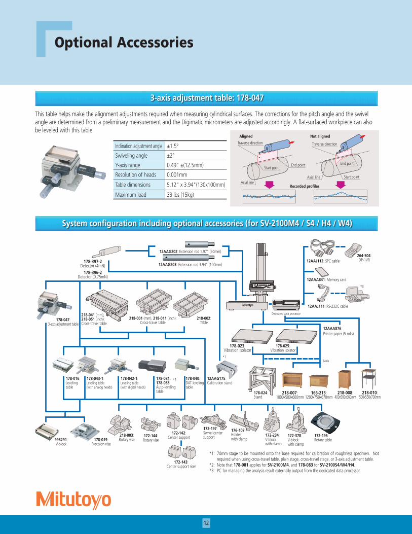
3-axis adjustment table: 178-047
This table helps make the alignment adjustments required when measuring cylindrical surfaces. The corrections for the pitch angle and the swivel angle are determined from a preliminary measurement and the Digimatic micrometers are adjusted accordingly. A flat-surfaced workpiece can also be leveled with this table.
System configuration including optional accessories (for SV-2100M4 / S4 / H4 / W4)
*1: 70mm stage to be mounted onto the base required for calibration of roughness specimen. Not required when using cross-travel table, plain stage, cross-travel stage, or 3-axis adjustment table.
*2: Note that 178-081 applies for SV-2100M4, and 178-083 for SV-2100S4/W4/H4.*3: PC for managing the analysis result externally output from the dedicated data processor.
Recorded profiles
Aligned Not aligned
End point
Axial lineAxial line
Traverse directionTraverse direction
End point
Start point
Start point
Inclination adjustment angle ±1.5°
Swiveling angle ±2°
Y-axis range 0.49" ±(12.5mm)
Resolution of heads 0.001mm
Table dimensions 5.12" x 3.94"(130x100mm)
Maximum load 33 lbs (15kg)

13
Optional Accessories
System configuration including optional accessories (for SJ-500 with optional manual column stand)
Roughness specimen (standard accessory): 178-601 Reference step specimen: 178-611 (mm), 178-612 (inch)
Display Ra = about 3 µm
Material Ni (TiN surface coating)
For sensitivity calibration of detector
Nominal value of step 2µm 10µm, 79µin 394µin
Roughness specimen: 178-604
For checking stylus tip
Display Ra = about 3 µm, about 0.4 µm
178-024:Stand
178-023:Vibration isolator
178-025:Vibration isolator
218-001 (mm), 218-011 (inch):Cross-travel table
218-002:Table
12AAG203: Extension rod 3.94” (100mm)
12AAG202: Extension rod 1.97” (50mm)
218-041 (mm), 218-051 (inch):Cross-travel table
176-107:Holder with clamp
172-197:Swivel center support 172-378:
V-block with clamp
172-196:Rotary table
172-234:V-block with clamp
172-142:Center support172-144:
Rotary vise218-003:Rotary vise178-019:
Precision vise998291:V-block
172-143:Center support riser
178-047:3-axis adjustment table
264-504:DP-1VR12AAJ112: SPC cable
12AAJ111: RS-232C cable
12AAA876:Printer paper (5 rolls)
Dedicated data processor
Printer
Data processing system (PC type)
Table
12AAA841: Memory card
178-397-2Detector (4mN)
178-396-2Detector (0.75mN)
218-007:1000x500x600mm
12AAG175:Calibration stand
*1
*3
*4
*2 178-040:DAT leveling table
178-081, 178-083:Auto-leveling table
178-016:Leveling table
178-043-1:Leveling table (with analog heads)
178-042-1:Leveling table (with digital heads)
218-008:400x500x660mm
166-215:1200x750x670mm
218-010:500x550x700mm
*1: 2.76" (70mm) stage to be mounted onto the base required for calibration of roughness specimen. Not required when using cross-travel table, plain stage, cross-travel stage, or 3-axis adjustment table.
*3: PC for managing the analysis result externally output from the dedicated data processor.*3: Only SJ-500P can be connected. Use a USB cable when connecting the SJ-500P main unit
and a PC. A USB cable is a standard accessory of the SJ-500P.
14
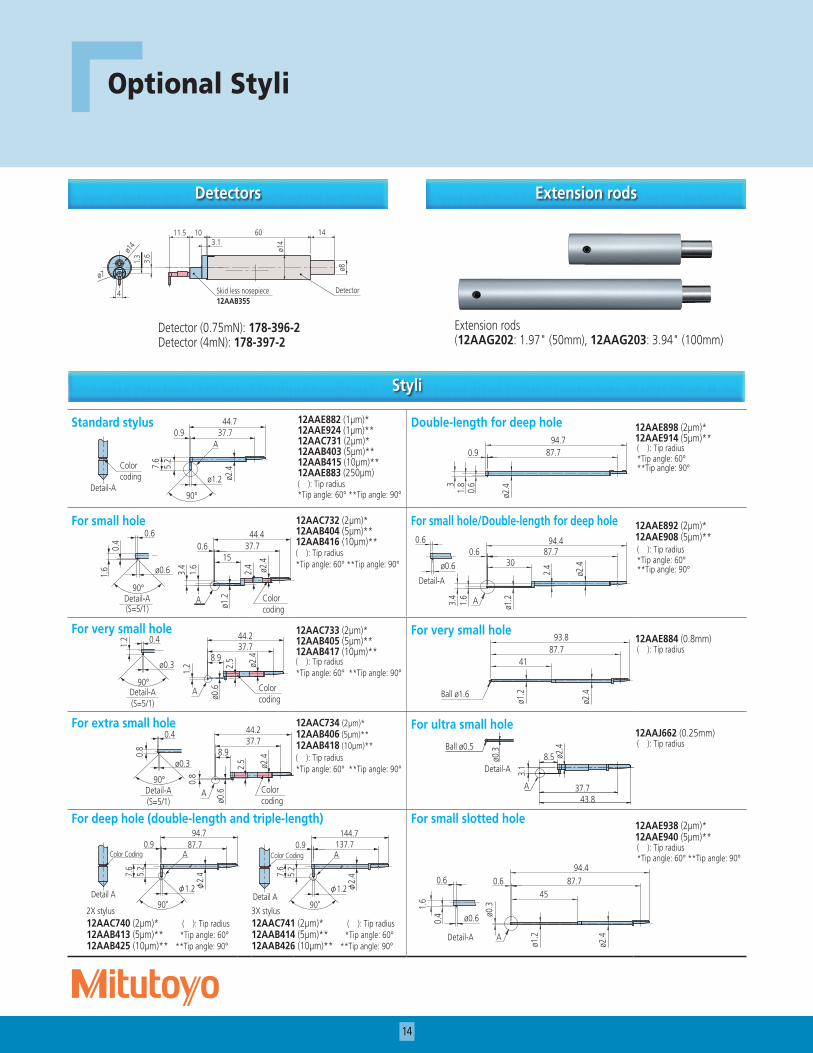
Optional Styli
Detectors Extension rods
Styli
Standard stylus 12AAE882 (1µm)*12AAE924 (1µm)**12AAC731 (2µm)*12AAB403 (5µm)**12AAB415 (10µm)**12AAE883 (250µm)( ): Tip radius*Tip angle: 60° **Tip angle: 90°
Double-length for deep hole 12AAE898 (2µm)*12AAE914 (5µm)**( ): Tip radius*Tip angle: 60° **Tip angle: 90°
For small hole 12AAC732 (2µm)*12AAB404 (5µm)**12AAB416 (10µm)**( ): Tip radius*Tip angle: 60° **Tip angle: 90°
For small hole/Double-length for deep hole 12AAE892 (2µm)*12AAE908 (5µm)**( ): Tip radius*Tip angle: 60° **Tip angle: 90°
For very small hole 12AAC733 (2µm)*12AAB405 (5µm)**12AAB417 (10µm)**( ): Tip radius*Tip angle: 60° **Tip angle: 90°
For very small hole12AAE884 (0.8mm)( ): Tip radius
For extra small hole 12AAC734 (2µm)*12AAB406 (5µm)**12AAB418 (10µm)**( ): Tip radius*Tip angle: 60° **Tip angle: 90°
For ultra small hole12AAJ662 (0.25mm)( ): Tip radius
For deep hole (double-length and triple-length) For small slotted hole 12AAE938 (2µm)*12AAE940 (5µm)**( ): Tip radius*Tip angle: 60° **Tip angle: 90°
2X stylus12AAC740 (2µm)* ( ): Tip radius12AAB413 (5µm)** *Tip angle: 60° 12AAB425 (10µm)** **Tip angle: 90°
3X stylus12AAC741 (2µm)* ( ): Tip radius12AAB414 (5µm)** *Tip angle: 60° 12AAB426 (10µm)** **Tip angle: 90°
1460
ø8
ø14
Detector
ø14
ø7
1011.53.1
3.6
1.3
Skid less nosepiece12AAB355
4
90°
0.9 37.7
7.6
44.7
ø2.4
ø1.2
5.2
A
Colorcoding
Detail-A
Colorcoding
Detail-A(S=5/1)
0.6
0.4
1.6 ø0.6
90°
ø2.415
ø1.2
3.4
2.4
1.6
0.6 37.744.4
A
Colorcoding
Detail-A(S=5/1)
0.41.2
ø0.3
90°
ø2.48.9
ø0.6
2.5
37.7
1.2
44.2
A
Colorcoding
Detail-A(S=5/1)
ø0.3
90°
0.8
0.4
ø2.4
37.7
2.5
ø0.6
8.9
44.2
0.8
A
深穴用
φ2.
4
87.70.9
φ1.2
90°
94.7
7.6
5.2
A
φ2.
4
137.70.9
7.6
144.7
φ1.2
90°
5.2
A
Detail A Detail A
Color Coding Color Coding
31.
80.
6
ø2.4
94.787.70.9
ø1.21.6
3.4
2.4
ø2.4
94.487.70.6
30
A
0.6
ø0.6
Detail-A
ø1.2
ø2.4Ball ø1.6
4187.7
93.8
極細穴形状用
φ2.
4φ0.
3
A
7
37.743.8
7
φ0.5超硬球
A部詳細
ø2.4
43.837.7
8.5
3.1
A
ø0.3Ball ø0.5
Detail-A
ø0.3
0.4
1.6
ø1.2
ø2.4
94.487.70.6
45
A
ø0.6
0.6
Detail-A
Detector (0.75mN): 178-396-2Detector (4mN): 178-397-2
Extension rods(12AAG202: 1.97" (50mm), 12AAG203: 3.94" (100mm)
15
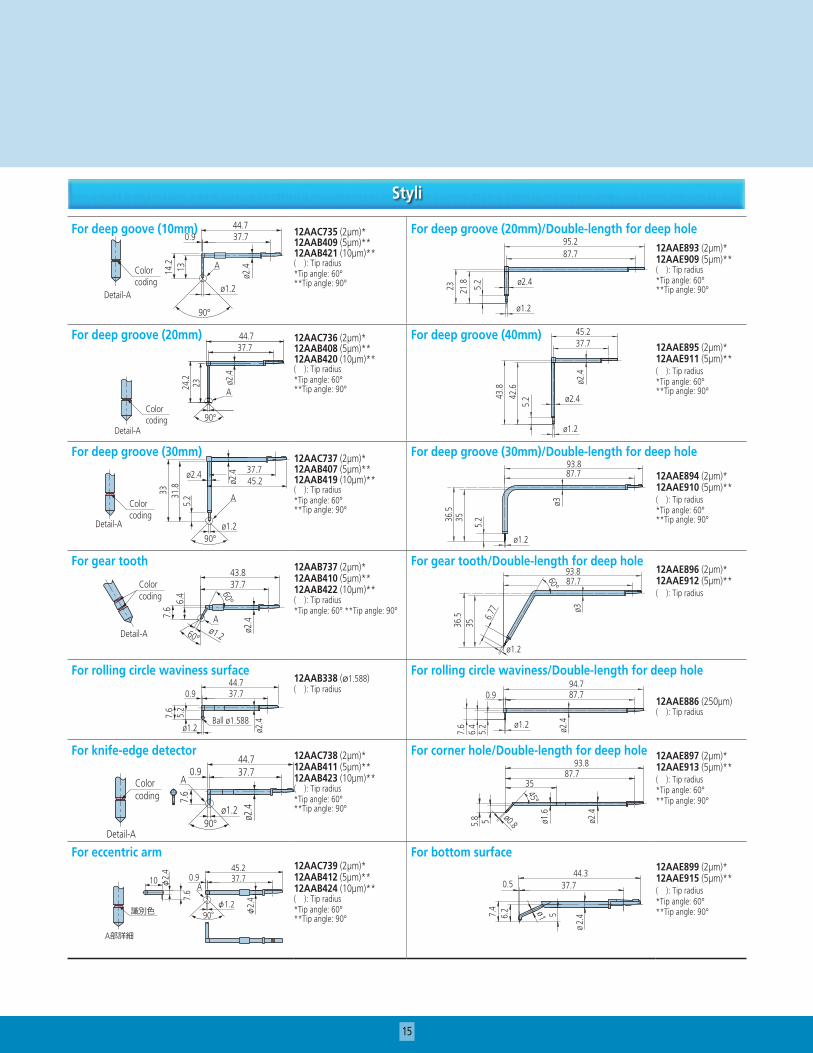
Styli
For deep goove (10mm) 12AAC735 (2µm)*12AAB409 (5µm)**12AAB421 (10µm)**( ): Tip radius*Tip angle: 60° **Tip angle: 90°
For deep groove (20mm)/Double-length for deep hole12AAE893 (2µm)*12AAE909 (5µm)**( ): Tip radius*Tip angle: 60° **Tip angle: 90°
For deep groove (20mm) 12AAC736 (2µm)*12AAB408 (5µm)**12AAB420 (10µm)**( ): Tip radius*Tip angle: 60° **Tip angle: 90°
For deep groove (40mm)12AAE895 (2µm)*12AAE911 (5µm)**( ): Tip radius*Tip angle: 60° **Tip angle: 90°
For deep groove (30mm) 12AAC737 (2µm)*12AAB407 (5µm)**12AAB419 (10µm)**( ): Tip radius*Tip angle: 60° **Tip angle: 90°
For deep groove (30mm)/Double-length for deep hole
12AAE894 (2µm)*12AAE910 (5µm)**( ): Tip radius*Tip angle: 60° **Tip angle: 90°
For gear tooth 12AAB737 (2µm)*12AAB410 (5µm)**12AAB422 (10µm)**( ): Tip radius*Tip angle: 60° **Tip angle: 90°
For gear tooth/Double-length for deep hole12AAE896 (2µm)*12AAE912 (5µm)**( ): Tip radius
For rolling circle waviness surface12AAB338 (ø1.588)( ): Tip radius
For rolling circle waviness/Double-length for deep hole
12AAE886 (250µm)( ): Tip radius
For knife-edge detector 12AAC738 (2µm)*12AAB411 (5µm)**12AAB423 (10µm)**( ): Tip radius*Tip angle: 60° **Tip angle: 90°
For corner hole/Double-length for deep hole 12AAE897 (2µm)*12AAE913 (5µm)**( ): Tip radius*Tip angle: 60° **Tip angle: 90°
For eccentric arm12AAC739 (2µm)*12AAB412 (5µm)**12AAB424 (10µm)**( ): Tip radius*Tip angle: 60° **Tip angle: 90°
For bottom surface12AAE899 (2µm)*12AAE915 (5µm)**( ): Tip radius*Tip angle: 60° **Tip angle: 90°
13
ø2.4
0.9
ø1.2
90°
14.2
37.744.7
AColorcoding
Detail-A
23
0.9
φ2.
4
24.2
φ1.2
90°
37.744.7
A識別色
A部詳細
Colorcoding
Detail-A90°
23 ø2.4
24.2
37.744.7
A
深溝用(20mm)
33 31.8
5.2
ø1.2
A
ø2.4
ø2.4
90°
37.745.2
Colorcoding
Detail-A
60°
60°
7.6
6.4
37.743.8
ø1.2 ø2.4A
Colorcoding
Detail-A
7.6
ø2.4
ø1.2
0.9 37.744.7
Ball ø1.588
5.2
7.6
ø2.4ø1.2
90°
37.70.944.7
AColorcoding
Detail-A
A37.70.9
90°φ1.2
45.2
7.6
10
φ2.
4
φ2.
4
識別色
A部詳細
Colorcoding
Detail-A
心違い用
90° ø2.4ø1.2
45.21.4 37.7
7.6
ø2.410
A
23 21.8 5.2
95.287.7
ø2.4
ø1.2
43.8
42.6
5.2
ø2.4
45.237.7
ø2.4
ø1.2
36.5
35
5.2
ø3
93.887.7
ø1.2
36.5
35
ø393.8
6.77
87.7
ø1.2
60°
94.70.9 87.7
ø1.2 ø2.4
5.2
6.4
7.6
93.887.7
35
ø0.8
45°
5.8 5 ø1
.6
ø2.4
7.4 ø1
0.5
56.2
ø2.
4
44.337.7
Small Tool Instruments andData Management
Test Equipment andSeismometers
Digital Scale and DRO Systems
Coordinate Measuring Machines
Sensor Systems
Optical Measuring
Form Measurement
Vision Measuring Systems
Aurora, Illinois(Corporate Headquarters)
Westford, Massachusetts
Huntersville, North Carolina
Mason, Ohio
Plymouth, Michigan
City of Industry, California
One Number to Serve You Better1-888-MITUTOYO (1-888-648-8869)
© 2009 Mitutoyo America Corporation, Aurora IL 0209-06 • Printed in USA • March 2009
Note: All information regarding our products, and in particular the illustrations, drawings, dimensional and perfor-mance data contained in this printed matter as well as other technical data are to be regarded as approximate average values. We therefore reserve the right to make changes to the corresponding designs. The stated standards, similar technical regulations, descriptions and illustrations of the products were valid at the time of printing. In addition, the latest applicable version of our General Trading Conditions will apply. Only quotations submitted by ourselves may be regarded as definitive.
Mitutoyo products are subject to US Export Administration Regulations (EAR). Re-export or relocation of Mitutoyo prod-ucts may require prior approval by an appropriate governing authority.
Trademarks and RegistrationsDesignations used by companies to distinguish their products are often claimed as trademarks. In all instances where Mitutoyo America Corporation is aware of a claim, the product names appear in initial capital or all capital letters. The appropriate companies should be contacted for more complete trademark and registration information.
We reserve the right to change specifications and prices without notice.