surface roughness and its effects in tribology - biotinet workshop slovenia/biotinet_kalin.pdf ·...
TRANSCRIPT
Mitjan Kalin, Janez Kogovšek
University of Ljubljana, Faculty of Mechanical Engineering
Centre for Tribology and Technical Diagnostics
Surface roughness and its effects in tribology
October 25, 2011
1st BioTiNet Workshop
• Surfaces and surface roughness (engineering perspective):
• meaning,
• measuring surface roughness,
• characterization of surfaces roughness,
• real contact area,
• plasticity index.
• Friction:
• basic concepts,
• dependence on surface properties.
Tribological surfaces
2
Surface properties
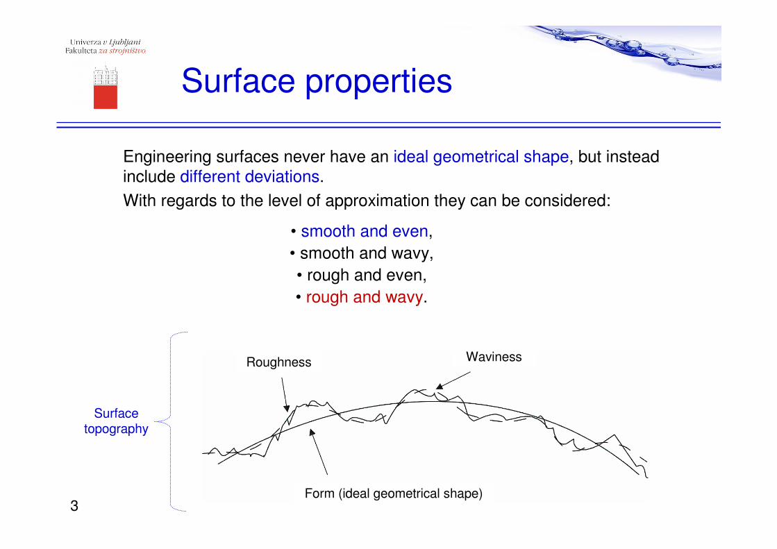
Engineering surfaces never have an ideal geometrical shape, but instead
include different deviations.
With regards to the level of approximation they can be considered:
• smooth and even,
• smooth and wavy,
• rough and even,
• rough and wavy.
Roughness Waviness
Form (ideal geometrical shape)
Surface topography
3
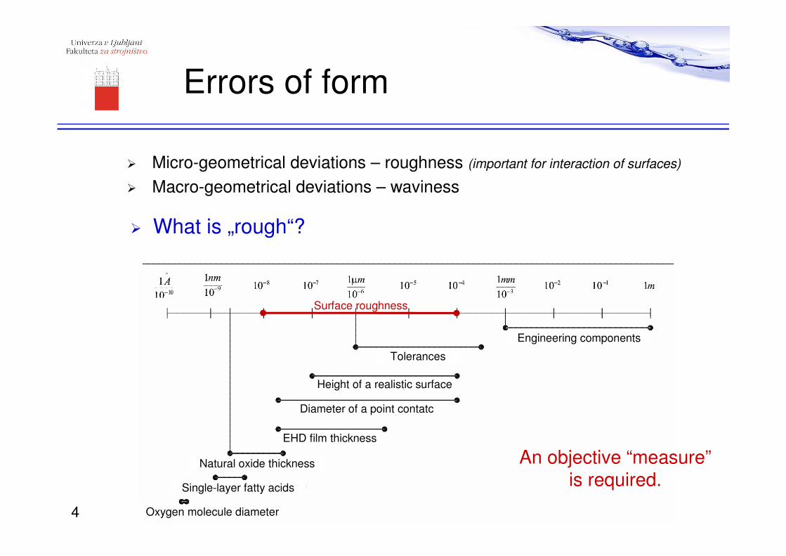
� Micro-geometrical deviations – roughness (important for interaction of surfaces)
� Macro-geometrical deviations – waviness
Errors of form
� What is „rough“?
Tolerances
Height of a realistic surface
Diameter of a point contatc
EHD film thickness
Single-layer fatty acids
Natural oxide thickness
Oxygen molecule diameter
Engineering components
Surface roughness
4
An objective “measure”is required.
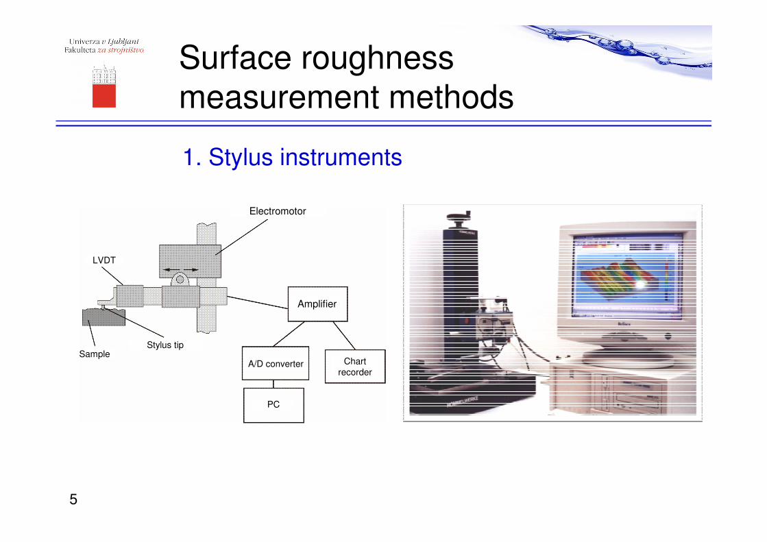
Surface roughness
measurement methods
1. Stylus instruments
Electromotor
Amplifier
A/D converter
PC
Chart
recorder
LVDT
SampleStylus tip
5
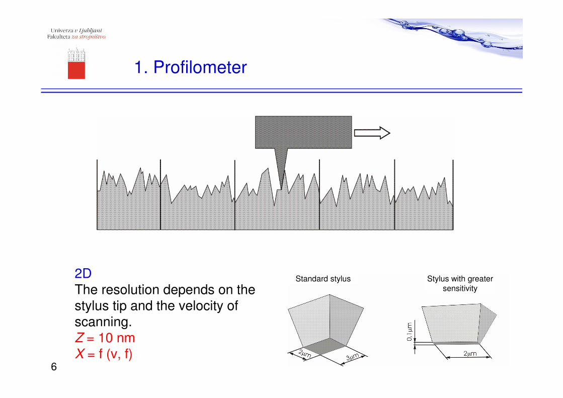
2DThe resolution depends on the stylus tip and the velocity of scanning.Z = 10 nmX = f (v, f)
Standard stylus Stylus with greater
sensitivity
1. Profilometer
6
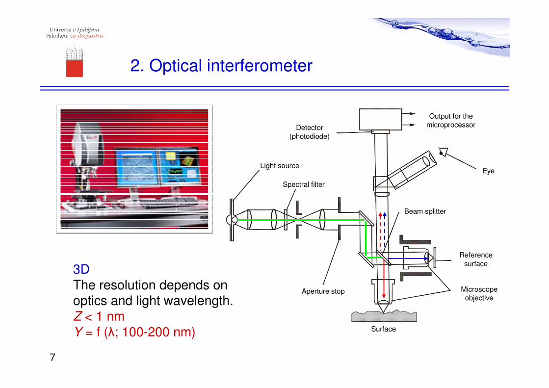
2. Optical interferometer
Surface
Aperture stop
Reference
surface
Microscope objective
Eye
Output for the
microprocessorDetector
(photodiode)
Light source
Spectral filter
Beam splitter
3DThe resolution depends onoptics and light wavelength.Z < 1 nmY = f (λ; 100-200 nm)
7
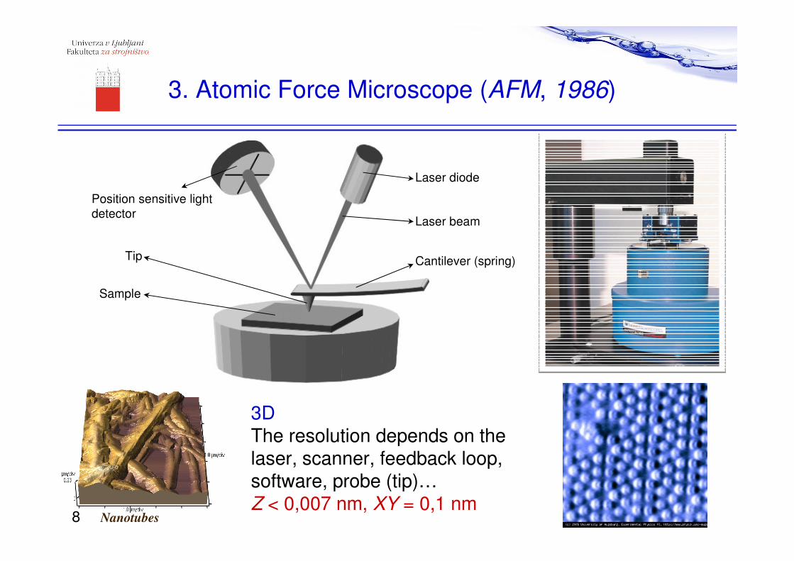
3. Atomic Force Microscope (AFM, 1986)
3DThe resolution depends on the laser, scanner, feedback loop, software, probe (tip)…Z < 0,007 nm, XY = 0,1 nm
Cantilever (spring)
Laser diode
Position sensitive light
detectorLaser beam
Tip
Sample
Nanotubes8
Analysis of the measured
surface roughness parameters
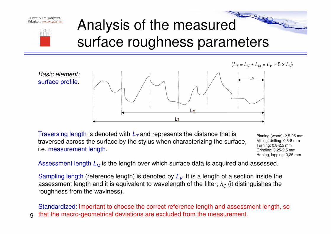
Traversing length is denoted with LT and represents the distance that is
traversed across the surface by the stylus when characterizing the surface,
i.e. measurement length.
Assessment length LM is the length over which surface data is acquired and assessed.
Sampling length (reference length) is denoted by LV. It is a length of a section inside the
assessment length and it is equivalent to wavelength of the filter, λC (it distinguishes the
roughness from the waviness).
Standardized: important to choose the correct reference length and assessment length, so
that the macro-geometrical deviations are excluded from the measurement.
Planing (wood): 2,5-25 mm
Milling, drilling: 0,8-8 mm
Turning: 0,8-2,5 mm
Grinding: 0,25-2,5 mm
Honing, lapping: 0,25 mm
(LT = LV + LM = LV + 5 x LV)
9
Basic element:
surface profile.
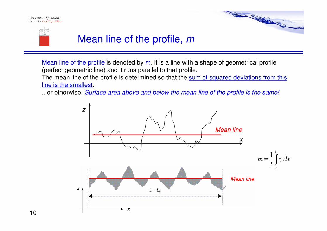
Mean line of the profile is denoted by m. It is a line with a shape of geometrical profile
(perfect geometric line) and it runs parallel to that profile.
The mean line of the profile is determined so that the sum of squared deviations from this
line is the smallest.
...or otherwise: Surface area above and below the mean line of the profile is the same!
Mean line of the profile, m
z
x
Mean line
L = LV
Mean line
z
x
0
1l
m z dxl
= ∫
10
Arithmetical mean deviation, Ra
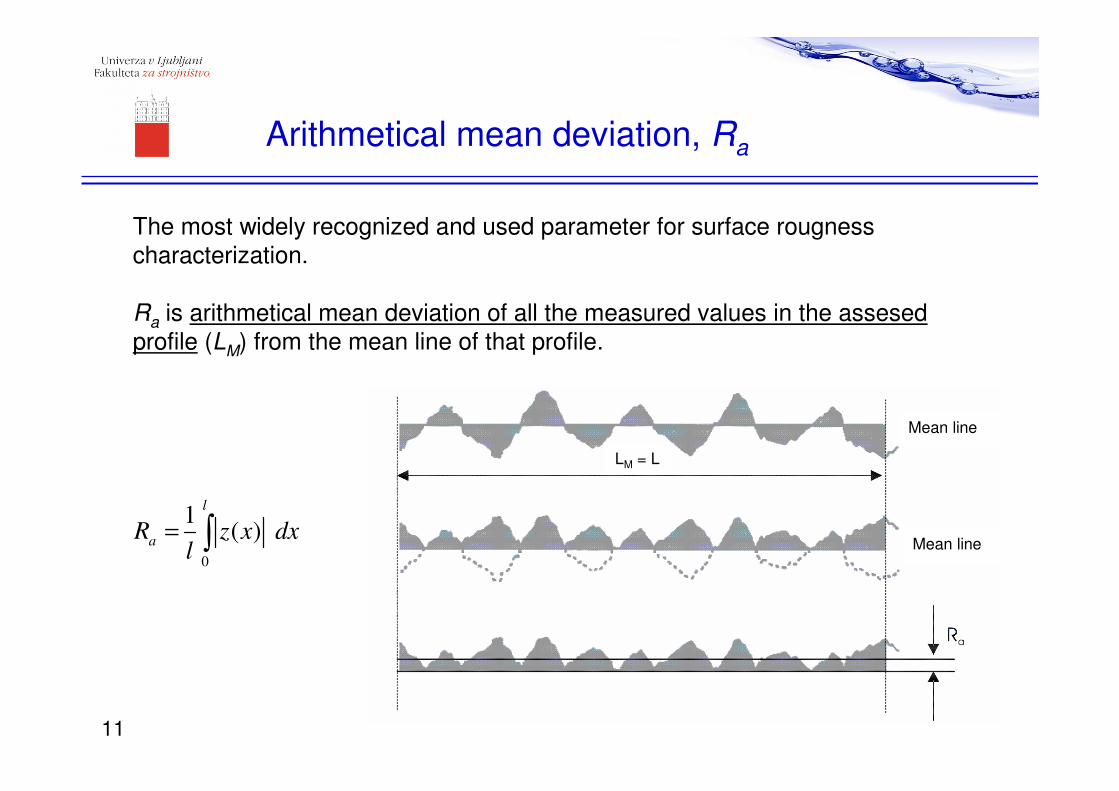
The most widely recognized and used parameter for surface rougness
characterization.
Ra is arithmetical mean deviation of all the measured values in the assesed
profile (LM) from the mean line of that profile.
0
1( )
l
aR z x dx
l= ∫
mLM = L
Mean line
Mean line
11
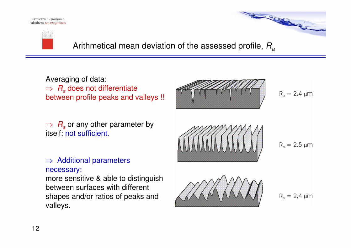
Averaging of data:
⇒ Ra does not differentiate
between profile peaks and valleys !!
⇒ Ra or any other parameter by
itself: not sufficient.
⇒ Additional parameters
necessary:
more sensitive & able to distinguish
between surfaces with different
shapes and/or ratios of peaks and
valleys.
Arithmetical mean deviation of the assessed profile, Ra
12
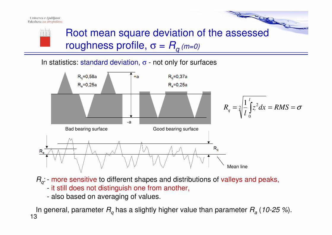
In statistics: standard deviation, σ - not only for surfaces
Root mean square deviation of the assessed
roughness profile, σ = Rq (m=0)
Rq: - more sensitive to different shapes and distributions of valleys and peaks,
- it still does not distinguish one from another,
- also based on averaging of values.
In general, parameter Rq has a slightly higher value than parameter Ra (10-25 %).
Good bearing surface
Mean line
Bad bearing surface
σ=== ∫ RMSdxzl
R
l
q2
0
21
13
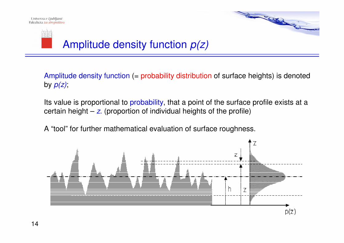
Amplitude density function (= probability distribution of surface heights) is denoted
by p(z);
Its value is proportional to probability, that a point of the surface profile exists at a
certain height – z. (proportion of individual heights of the profile)
A “tool” for further mathematical evaluation of surface roughness.
Amplitude density function p(z)
14
Z = positive(Sk = negative)+z
-z
p(z)
profile
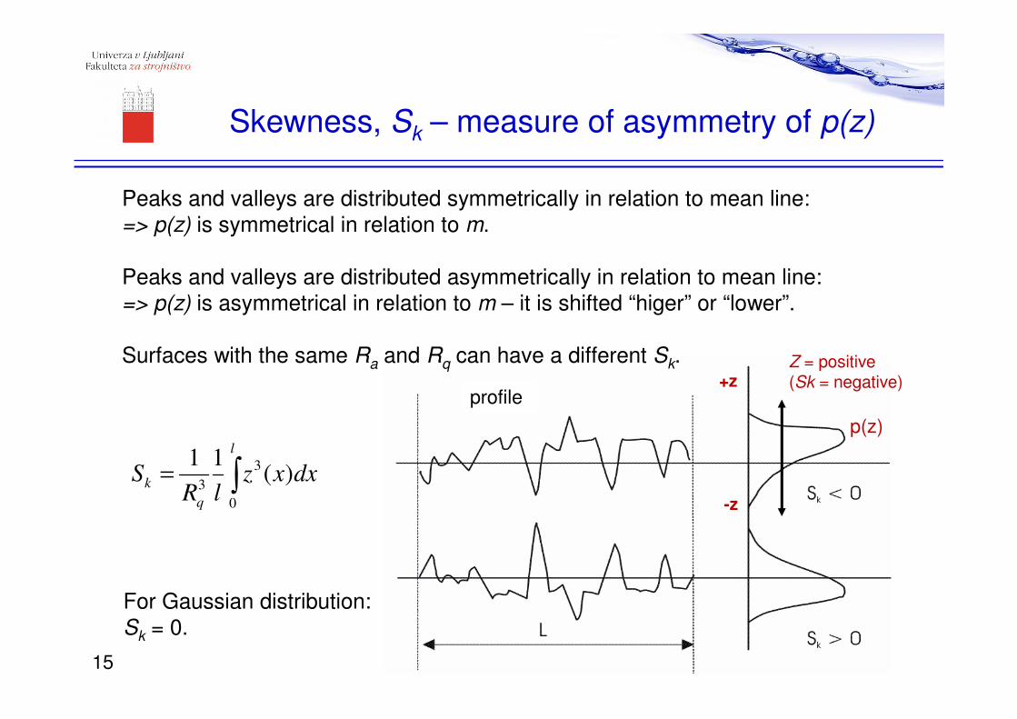
Peaks and valleys are distributed symmetrically in relation to mean line:
=> p(z) is symmetrical in relation to m.
Peaks and valleys are distributed asymmetrically in relation to mean line:
=> p(z) is asymmetrical in relation to m – it is shifted “higer” or “lower”.
Surfaces with the same Ra and Rq can have a different Sk.
Skewness, Sk – measure of asymmetry of p(z)
For Gaussian distribution:
Sk = 0.
3
3
0
1 1( )
l
k
q
S z x dxR l
= ∫
15
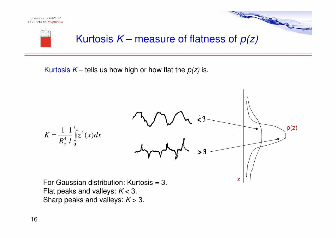
Kurtosis K – tells us how high or how flat the p(z) is.
For Gaussian distribution: Kurtosis = 3.
Flat peaks and valleys: K < 3.
Sharp peaks and valleys: K > 3.
Kurtosis K – measure of flatness of p(z)
∫=
l
q
dxxzlR
K0
4
4)(
11 p(z)
z
16
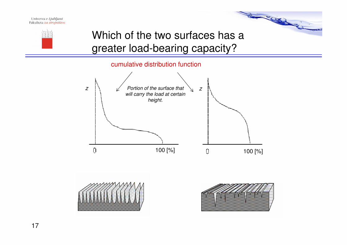
Which of the two surfaces has a
greater load-bearing capacity?
100 [%] 100 [%]
z z
17
cumulative distribution function
Portion of the surface that will carry the load at certain
height.
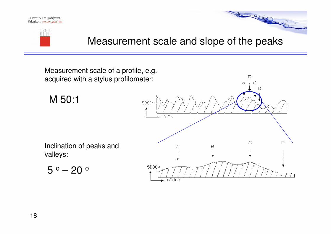
Measurement scale and slope of the peaks
5 o – 20 o
M 50:1
Measurement scale of a profile, e.g.
acquired with a stylus profilometer:
Inclination of peaks and
valleys:
18
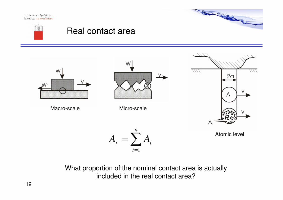
Real contact area
Micro-scale
Atomic level
∑=
=n
i
ir AA1
What proportion of the nominal contact area is actually included in the real contact area?
Macro-scale
19
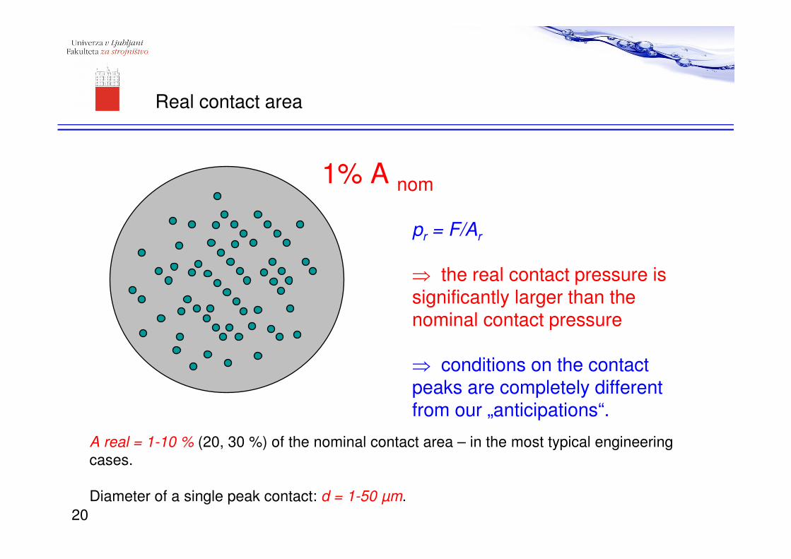
1% A nom
A real = 1-10 % (20, 30 %) of the nominal contact area – in the most typical engineering
cases.
Diameter of a single peak contact: d = 1-50 µm.
pr = F/Ar
⇒ the real contact pressure is significantly larger than the nominal contact pressure
⇒ conditions on the contact peaks are completely different from our „anticipations“.
Real contact area
20
Difficult to determine – for usage in “models”.
(Sometimes the value is measured/determined but is not valid in general...)
Calculations – assumptions!
- Asperities are randomly distributed,
- are of different sizes (height, width),
- asperities in interactions with each other get changed in very short time intervals
(position),
- asperities are constantly modified by wear,
- wear particles influence the real contact area.
Mesurement methods:
- static (replica...); are not valid for dynamic contacts,
- contact resistance,
- pressure sensor (materials with a known phase transformation),
- contacts cannot be seen (closed); visible contacts (sapphire) are not valid in general.
Determination of the real contact area
21
Plasticity index
2
*
rH
E σψ =
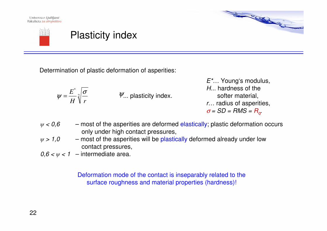
Determination of plastic deformation of asperities:
... plasticity index.
E*… Young‘s modulus,
H... hardness of the
softer material,
r… radius of asperities,
σ = SD = RMS = Rq.
ψ < 0,6 – most of the asperities are deformed elastically; plastic deformation occurs
only under high contact pressures,ψ > 1,0 – most of the asperities will be plastically deformed already under low
contact pressures,0,6 < ψ < 1 – intermediate area.
Deformation mode of the contact is inseparably related to the
surface roughness and material properties (hardness)!
ψ
22
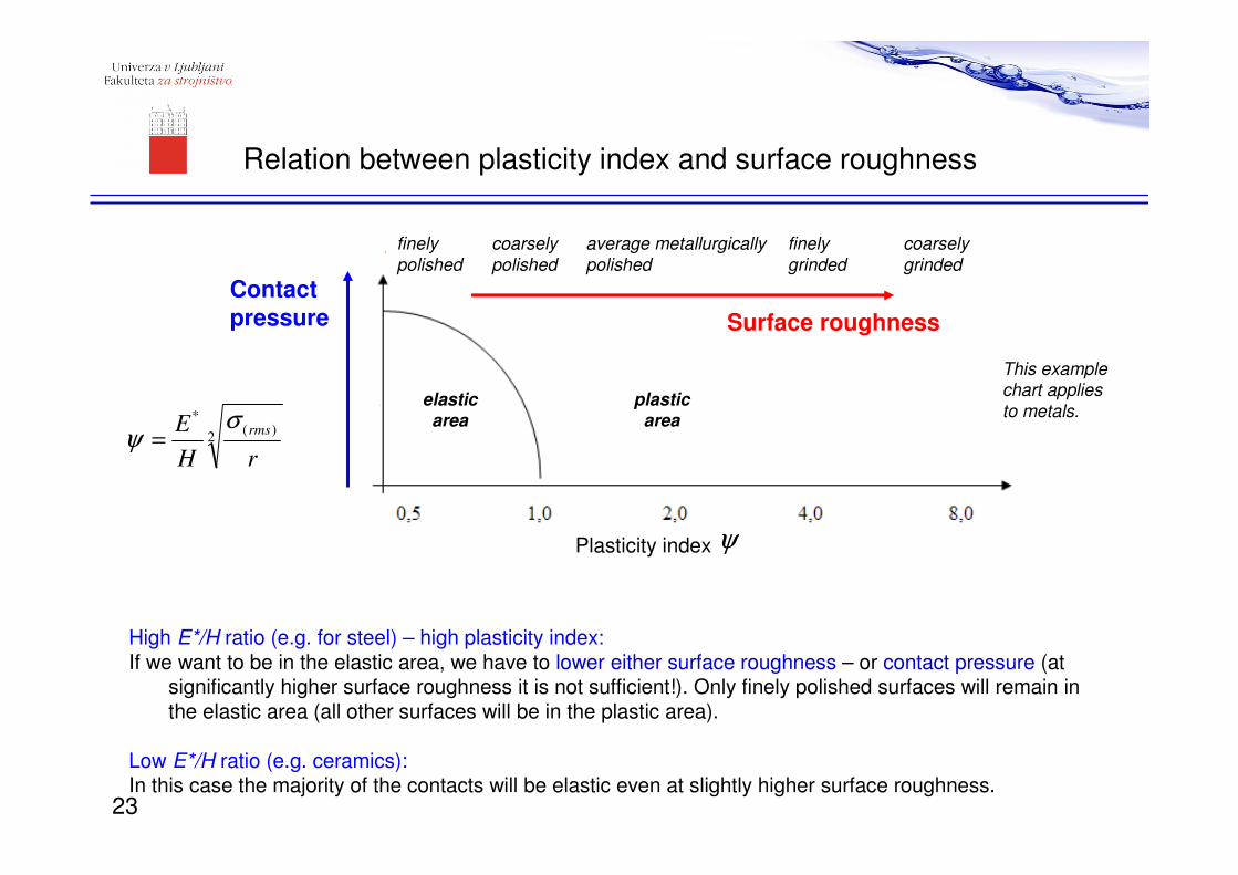
Relation between plasticity index and surface roughness
High E*/H ratio (e.g. for steel) – high plasticity index:If we want to be in the elastic area, we have to lower either surface roughness – or contact pressure (at
significantly higher surface roughness it is not sufficient!). Only finely polished surfaces will remain in the elastic area (all other surfaces will be in the plastic area).
Low E*/H ratio (e.g. ceramics):In this case the majority of the contacts will be elastic even at slightly higher surface roughness.
Contact pressure Surface roughness
This example chart applies to metals.
2)(
*
rH
E rmsσψ =
Plasticity index ψ
finely polished
coarsely polished
average metallurgically polished
finely grinded
coarsely grinded
elastic area
plastic area
23
Surface roughness & friction?
24
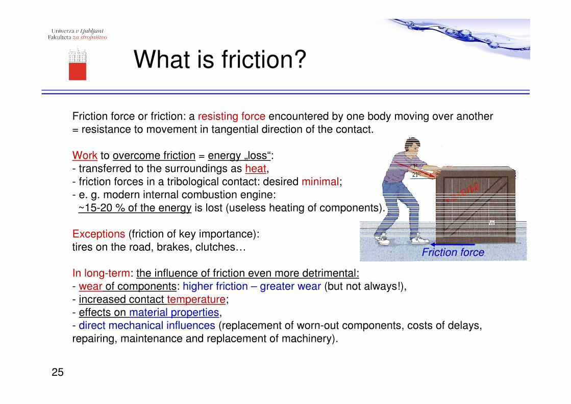
What is friction?
Friction force or friction: a resisting force encountered by one body moving over another
= resistance to movement in tangential direction of the contact.
Work to overcome friction = energy „loss“:
- transferred to the surroundings as heat,
- friction forces in a tribological contact: desired minimal;
- e. g. modern internal combustion engine:
~15-20 % of the energy is lost (useless heating of components).
Exceptions (friction of key importance):
tires on the road, brakes, clutches…
In long-term: the influence of friction even more detrimental:
- wear of components: higher friction – greater wear (but not always!),
- increased contact temperature;
- effects on material properties,
- direct mechanical influences (replacement of worn-out components, costs of delays,
repairing, maintenance and replacement of machinery).
Friction force
25
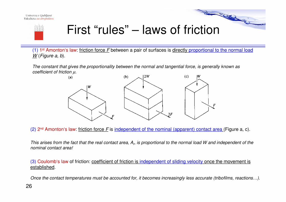
First “rules” – laws of friction
(1) 1st Amonton‘s law: friction force F between a pair of surfaces is directly proportional to the normal loadW (Figure a, b).
The constant that gives the proportionality between the normal and tangential force, is generally known as
coefficient of friction µ.
(2) 2nd Amonton‘s law: friction force F is independent of the nominal (apparent) contact area (Figure a, c).
This arises from the fact that the real contact area, Ar, is proportional to the normal load W and independent of the
nominal contact area!
(3) Coulomb‘s law of friction: coefficient of friction is independent of sliding velocity once the movement is established.
Once the contact temperatures must be accounted for, it becomes increasingly less accurate (tribofilms, reactions…).
26
?constW
Ft ==µ
τ×= rt AF
coefficient of friction,
tangential force,
load.
tF
W
µ −
−
−
real contact area,
shear strength specific resistance to shearing.
rA
τ
−
− =
Understanding friction
τ depends on physical (chemical) properties of shearing of surfaces: formation and type of bonds between surfaces and on the manner these bonds are broken.
depends on mechanical properties of the contact surface: on the deformation – it depends on roughness, hardness, elasticity, toughness, collapse mode of material.
rA
The value of friction coefficient:
- related to the material pair in contact (supposedly constant for each material pair),
- but also to the physical conditions of sliding!
- Universal model for friction (not constant) does not exist!27
Prevelika razdalja, da bi prišlo do adhezije.
x
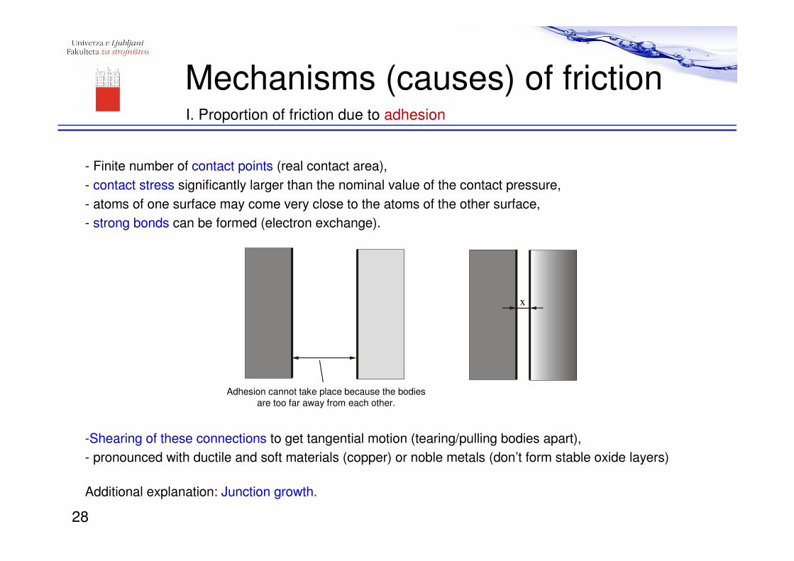
Adhesion cannot take place because the bodies
are too far away from each other.
Mechanisms (causes) of frictionI. Proportion of friction due to adhesion
- Finite number of contact points (real contact area),
- contact stress significantly larger than the nominal value of the contact pressure,
- atoms of one surface may come very close to the atoms of the other surface,
- strong bonds can be formed (electron exchange).
-Shearing of these connections to get tangential motion (tearing/pulling bodies apart),
- pronounced with ductile and soft materials (copper) or noble metals (don’t form stable oxide layers)
Additional explanation: Junction growth.
28
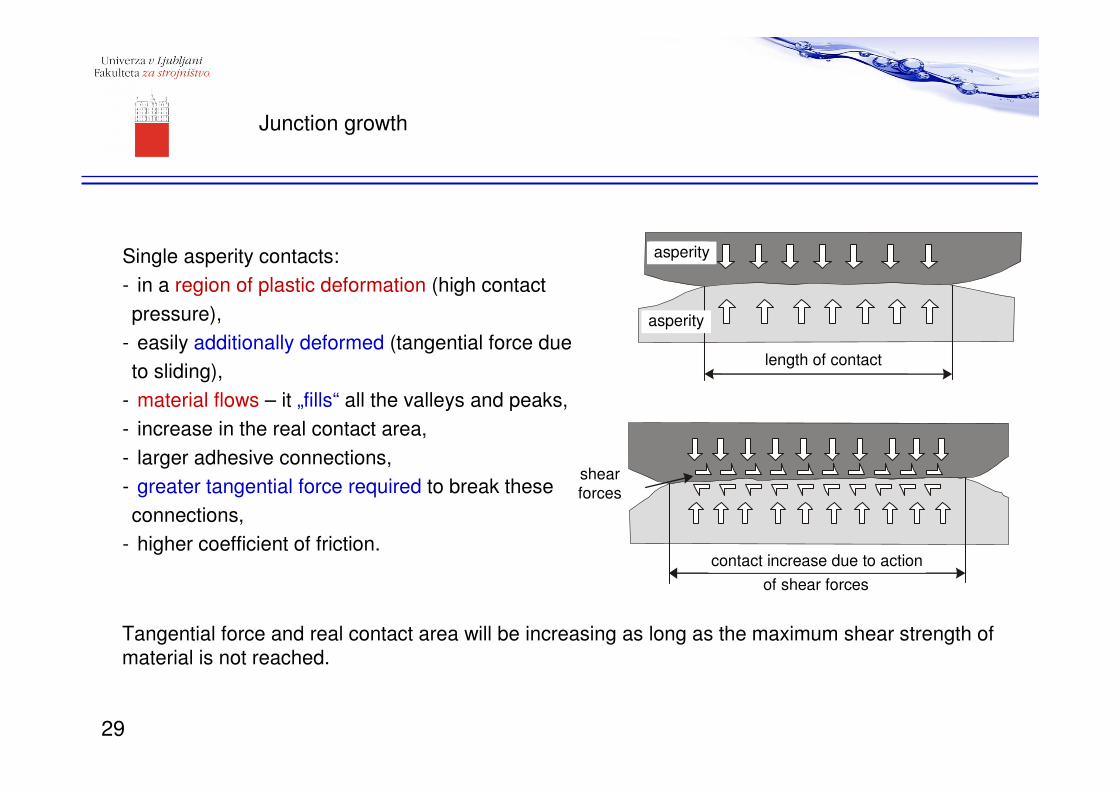
Junction growth
Single asperity contacts:
- in a region of plastic deformation (high contact
pressure),
- easily additionally deformed (tangential force due
to sliding),
- material flows – it „fills“ all the valleys and peaks,
- increase in the real contact area,
- larger adhesive connections,
- greater tangential force required to break these
connections,
- higher coefficient of friction.
Tangential force and real contact area will be increasing as long as the maximum shear strength of
material is not reached.
asperiteta
asperiteta
dolžina kontakta
povečanje kontakta zaradi delovanja strižnih sil
strižne sile
asperity
asperity
length of contact
shear
forces
contact increase due to action
of shear forces
29
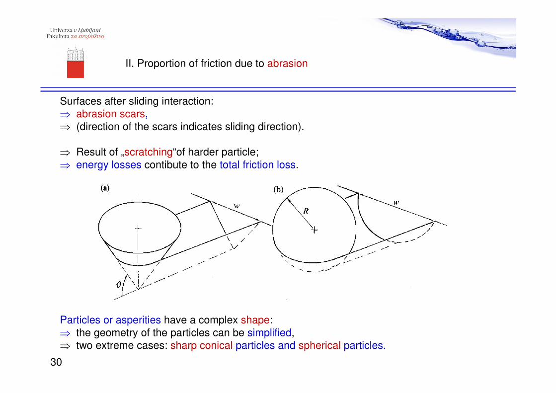
II. Proportion of friction due to abrasion
Surfaces after sliding interaction:
⇒ abrasion scars,
⇒ (direction of the scars indicates sliding direction).
⇒ Result of „scratching“of harder particle;
⇒ energy losses contibute to the total friction loss.
Particles or asperities have a complex shape:
⇒ the geometry of the particles can be simplified,
⇒ two extreme cases: sharp conical particles and spherical particles.
30
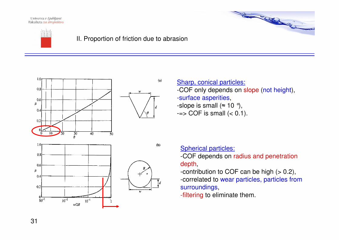
Sharp, conical particles:
-COF only depends on slope (not height),
-surface asperities,
-slope is small (≈ 10 °),
-=> COF is small (< 0.1).
Spherical particles:
-COF depends on radius and penetration
depth,
-contribution to COF can be high (> 0.2),
-correlated to wear particles, particles from
surroundings,
-filtering to eliminate them.
II. Proportion of friction due to abrasion
31

III. Proportion of friction due to deformation of asperities
Coefficient of friction depends on:
-slope of asperities,
-engagement angle of asperities,
-angle of deformation of material.
θ , kot dejanskega oprijema delcev
α = θ
slope of asperities
att
ack a
ngle
of
asp
eritie
s
Coefficient of friction due to deformation of
asperities is indicated to be very high (0.4-1.0)!
High COF values similar to static friction!
⇒it is likely that most deformations occur
before the beginning of sliding.
32
Summary
• Surface topography includes roughness, wavines and form.
• Surface roughness is measured by profilometry, optical
interferometry, AFM.
• Some of the main parameters for characterization are: Ra, Rq, Rz,
Sk, K, tp.
• Surface roughness has influence on the real contact area and type
of surface deformation (elastic/plastic – plasticity index).
• Surface roughness influences all of the main causes of friction:
adhesion, abrasion, deformation of asperities.
Thank you for attention!33