surface & coatings technology - iaunresearch.iaun.ac.ir/pd/kasiri/pdfs/paperm_6130.pdf ·...
TRANSCRIPT

Surface & Coatings Technology 277 (2015) 30–43
Contents lists available at ScienceDirect
Surface & Coatings Technology
j ourna l homepage: www.e lsev ie r .com/ locate /sur fcoat
Microstructural characterization, biocorrosion evaluationand mechanical properties of nanostructured ZnO and Si/ZnOcoated Mg/HA/TiO2/MgO nanocomposites
Shahrouz Zamani Khalajabadi a, Mohammed Rafiq Abdul Kadir a,⁎, Sudin Izman b, Masoud Kasiri-Asgarani c
a Medical Devices & Technology Group (MEDITEG), Faculty of Biosciences and Medical Engineering, Universiti Teknologi Malaysia (UTM), 81310 Johor Bahru, Johor, Malaysiab Department of Materials, Manufacturing and Industrial Engineering, Faculty of Mechanical Engineering, Universiti Teknologi Malaysia (UTM), 81310 Johor Bahru, Johor, Malaysiac Materials Engineering Department, Najafabad Branch, Islamic Azad University, Najafabad, Isfahan, Iran
⁎ Corresponding author.E-mail addresses: [email protected] (S.Z. K
[email protected] (M.R. Abdul Kadir).
http://dx.doi.org/10.1016/j.surfcoat.2015.07.0060257-8972/© 2015 Elsevier B.V. All rights reserved.
a b s t r a c t
a r t i c l e i n f oArticle history:Received 24 February 2015Revised 4 July 2015Accepted in revised form 6 July 2015Available online 12 July 2015
Keywords:Mg/HA/TiO2/MgO nanocompositeZnO-coatingSi-coatingBiodegradationMicrostructureRF magnetron sputtering
Nano-ZnO monolayer and nano-Si/ZnO double-layer coatings were deposited on a Mg/HA/TiO2/MgO nanocom-posite using radio frequency magnetron sputtering. The composition and surface morphology of the specimenswere characterized by X-ray diffraction, X-ray photoelectron spectroscopy, Fourier-transform infrared spectros-copy, transmission electronmicroscopy, atomic forcemicroscopy andfield-emission scanning electronmicrosco-py equippedwith energy dispersive X-ray spectroscopy. Potentiodynamic polarization and immersion testswereused to investigate the corrosion behavior of samples. The Si/ZnO nanocomposite coating, which had an averagethickness of 1.7 μm, exhibited a uniform and dense film, consisting of a ZnO outer layer (~1.1 μm thick) and a Siinner layer (~0.6 μm thick). However, some pores and cracks were observed in the ZnO monolayer coating(~1.5 μm thick). In addition, the Si and ZnO nanoparticles had a spherical morphology with an average particlesize of 28–40 nm. Higher polarization resistance values were obtained for the nano-Si/ZnO coated sample(~2.55 kΩ cm2) compared with that of the ZnO coated (~1.34 kΩ cm2) and uncoated (~0.14 kΩ cm2) samplesin a simulated body fluid (SBF). The results from the hydrogen evolution studies indicated that the nano-Si/ZnO-coated sample had a lower degradation rate (1.07 ml/cm2/day) than the ZnO-only coated sample(2.25 ml/cm2/day) and the uncoated sample (4.42 ml/cm2/day). After 168 h of immersion in a SBF solution, alarger amount of hydroxyapatite precipitated on the Si/ZnO coating than the ZnO coating, which resulted in animprovement in the bioactivity. The compressive strength and elongation of uncoated Mg/HA/TiO2/MgOdecreased from 253 MPa and 9.8% to 104 MPa and 5.2% after 28 days of immersion in SBF solution, whereasthe Si/ZnO coated sample indicated a compressive strength of 148 MPa and elongation of 7.2%. Therefore, thedouble-layer Si/ZnO composite coating prepared by magnetron sputtering on the Mg/HA/TiO2/MgO nanocom-posite is more suitable for biomedical applications.
© 2015 Elsevier B.V. All rights reserved.
1. Introduction
In recent years, much attention has been focused on biodegradablemetals due to their potential application for use in temporary implants,such as orthopedic implants [1,2] and cardiovascular stents [3].Although polymers are dominant in the current medical market,metal-based alloys due to their superior combination of strength andductility over polymers have been proposed as better biodegradablematerials for load-bearing applications. The primary biodegradablemetals are iron- andmagnesium-based alloys, which degrade relativelysafely in the human body [4]. In particular, magnesium-based alloys arevery promising for use in biomedical applications [5]. Recently, the first
halajabadi),
commercially availableMg-based orthopedic product has emerged. TheMAGNEZIX® screw obtained the CE mark for medical devices usedin medical applications within Europe. Animal models have alreadybeen conducted on other potential magnesium products, includingmicroclips for laryngeal microsurgery, plates and nails, and wound-closing devices [6]. The magnesium ion has an essential role in humanmetabolism [7], stimulates the growth of bone cells, aids in the forma-tion of biological apatite and accelerates bone tissue healing process[2]. In addition, the low density (1.74 g/cm3) and similar Young's mod-ulus of biodegradable Mg alloys to that of natural bone [5,8] led to theapplication of these alloys as biomaterials during the past decade. How-ever, quick degradation ofmagnesium-basedmaterials in the high chlo-ride environment of the physiological solution caused the temporaryimplants to lose their mechanical integrity before the tissue has suffi-cient time to heal. In addition, the accumulation of hydrogen gas upondegradation in a physiological solution restricts the clinical applications

31S.Z. Khalajabadi et al. / Surface & Coatings Technology 277 (2015) 30–43
of Mg-based implants [9]. Therefore, improvement in the corrosionresistance of Mg alloys is essential while the mechanical properties arenot compromised or even enhanced for increasing their potentialapplications. Alloying with non-toxic elements, such as Ca [10], Zn[11], and Si [12], to form magnesium-matrix composites (MMCs) withbioceramics of natural human bone compositions, such as hydroxylapa-tite (HA) [13–15] and β-tricalcium phosphate (β-TCP) [16], as well assurface treatment have beenwidely employed to decrease the corrosionrate of Mg-based materials [17–22]. Surface modification techniques,such as physical vapor deposition (PVD) [23], alkaline heat treatment[19], micro-arc oxidation [24], electrodeposition [22,23], the sol–gelmethod [17,18], andmagnetron sputtering [25], are effective for solvingthese problems.
Silicon (Si) is a biocompatible element that is fundamental for thegrowth and development of bone, teeth, and some invertebrate skeletalparts. Si has an essential role in the bone calcification process [26]. Inrecent studies, the formation of an apatite layer in an artificial physio-logical solution was enhanced by the incorporation of Si into HA [27].The full degradation of silicon into non-toxic silicic acid in physiologicalsolutions may be due to the use of nanostructured porous silicon forbiomedical applications [28,29]. However, silicon-based coatings, suchas Si/HA [23], SiC [30], SiN [31], and Bioglass [17] have been employedin biomedical applications. In addition, the fabrication of a Si film onMg alloys resulted in an improved corrosion rate in a simulated bodyfluid (SBF) [23]. Li et al. [28] reported that deposition of a Si coating byplasma enhanced chemical vapor deposition (PECVD) effectivelydecreased the degradation rate of the WE43 Mg alloy. In addition, asignificant enhancement in the corrosion resistance of the WE43 Mgalloy by Si implantation was reported by Jamesh et al. [29].
The addition of zinc oxide particles in a Mg-rich epoxy primerimproved the protective behavior of theMg-rich primer on AZ91Dmag-nesium alloy and decreased the corrosion rate of this alloy in corrosivemedia [32]. In addition, ZnO has been added to a coating bath tostrengthen the corrosion resistance of a zinc phosphate-based coatingon the AZ91Dmagnesium alloy [33]. ZnO also offers several advantages,such as non-toxicity, biocompatibility, and excellent antibacterial activ-ity. In addition, ZnO is abundant in nature [32,34–36]. The potential ofnanostructured ZnO for use in biosensors [37], bioimaging, and drug de-livery [35] has led to the extensive investigation of biomedical applica-tions. The RF magnetron sputtering technique, which has been widelyused to fabricate ZnO thin films, has specific advantages for film growth,such as good interfacial adhesion to the substrate and a high packingdensity of the grown film [38–40]. As reported by Shen and Zuo, theadhesion of Mg-rich primer as a protective coating to the Mg-basedsubstrate increased by the addition 10% of zinc oxide (ZnO) nanoparti-cles to the primer. As a result, crack propagation between the primerand the substrate may be hampered under tension by addition of zincoxide nanoparticles [32]. RF magnetron sputtering is also a commonlyused method to deposit silicon-based coatings [41]. Therefore, the pur-pose of this study is to decrease the corrosion rate of the Mg/HA/TiO2/MgO nanocomposite by RF magnetron sputtering of a double-layer Si/ZnO coating that consists of a nano-Si inner layer and a nano-ZnOouter layer. In recent studies, microstructure, biocorrosion behaviorand merits of Mg/HA/TiO2/MgO nanocomposite after different times ofball milling and post-annealing at 500 and 630 °C have been investigat-ed [14,15]. In addition, the surface characteristics, in vitro biocorrosionbehavior and mechanical properties of the single-layer ZnO coatingcompared with the double-layer Si/ZnO coating on the Mg/HA/TiO2/MgO nanocomposite were investigated in this study.
2. Materials and method
Magnesium powder (Mg, 99.9% purity, 325 mesh), nano-hydroxyapatite (HA, Ca10(PO4)6(OH)2, 99.9% purity, average parti-cle size b 100 nm), anatase (TiO2, 99.9% purity, average particlesize b 100 nm) and periclase (MgO, 99.9%, average particle
size b 100 nm), which were supplied by SIGMA-ALDRICH, were usedas the initial materials. The powder mixtures were dried and subse-quentlymixed using a planetary ball mill for 2 h in an argon atmosphere.Uniaxial pressingwas applied at a pressure of 840MPa to fabricate cylin-drical compacted specimens that were 12 mm in diameter and 5 mm inheight as the substrate for the coating process, immersion and electro-chemical tests. A Philips diffractometer with Cu Kα radiation (λ =0.15406 nm) was used for the XRD measurements. The XRD patternanalysis was performed using the “MDI jade6” software. The surfaceelemental composition and valance state of the surface elements wereidentified by X-ray photoelectron spectrum (XPS). Fourier-transforminfrared (FTIR) spectroscopywas used to determine the surface function-al groups of the uncoated and coated samples. The FTIR spectrum wasrecorded in a spectral range of 4000–350 cm−1. The morphologies andparticle sizes were analyzed using field-emission scanning electronmicroscopy (FESEM, JEOL JSM 6380LA) and transmission electronmicroscopy (TEM, Philips CM10). AFM (SPI3800)was used to investigateof the growthmorphology and roughness of the samples. Field-emissionscanning electron microscopy (FESEM, JEOL JSM 6380LA) was used toinvestigatemicrostructure of socked samples after 28 days of immersionin SBF solution at 37 °C.
The electrochemical testwas recorded at 37 °C in a glass cell contain-ing 250 ml of Kokubo simulated body fluid (SBF) at a pH of 7.56–7.66using aVersastat3 potentiostat/galvanostat (PrincetonApplied Research).Concentrated solutions of NaCl (8.037 g/L), NaHCO3 (0.351 g/L), KCl(0.224 g/L), K2HPO4·3H2O (0.231 g/L), MgCl2·6H2O (0.310 g/L), CaCl2(0.294 g/L), Na2SO4 (0.073 g/L), tris–hydroxymethyl aminomethane(CH2OH)3 CNH2 (6.062 g/L) and 1.0 mol/L HCl (40 ml) were used toprepare the SBF solution by pipetting the calculated amounts [42]. Theexposed surface area of the tested specimens in the SBF solution was0.402 cm2. In addition, a saturated calomel electrode (SCE) and a graphiterod were used as the reference and counter electrode, respectively, andthe specimen was the working electrode in a three-electrode cell for thepotentiodynamic polarization tests. All of the experiments were recordedat a scan rate of 0.5 mV/s starting at−250 mVSCE below the open circuitpotential. The software allows us to manually control this fitting. Asegment of the curve from Ecorr VSCE was selected to perform the Tafelfittings, and icorr was subsequently estimated from the value, where thefit intercepted the potential value of the true Ecorr VSCE [43]. The repro-ducibility of the results was verified by three times performing eachexperiment. All of the potentialswere referred to the SCE. A 168h immer-sion in the SBF solutionwas employed tomeasure thehydrogen evolutionrate. A sample was immersed in a beaker that was covered with a funnelto collect the evolved hydrogen in a burette above the funnel. The hydro-gen evolution rate was calculated in ml/cm2/day prior to renewing thesolution, and the volume of hydrogen was measured with a scaledburette. The SBF solution was refreshed every day during immersiontest up to 28 days.
RFmagnetron sputtering equipment (HVC Penta Vacuum)was usedto separately deposit the nano-ZnO monolayer (~1.5 μm thick) andnano-Si/ZnO double-layer coatings, which consisted of a ~1.1 μm thickSi inner layer and a 0.6 μmthick ZnO space layer. The cylindrical samplesof the Mg/HA/TiO2/MgO nanocomposite were mechanically groundwith SiC emery paper up to #2000. Then, the cylindrical samples wereultrasonically cleaned in acetone, alcohol and distilled water for 15 minprior to the coating process being performed in a vacuum chamber. Argas was supplied to the vacuum chamber for 40 min to complete thesample cleaning process. The base pressure of the chamber was adjustedto less than 2.55 × 10⁻⁴ Pa. The RFmagnetron sputtering technique wasperformedwith argon as the sputtering gas at a substrate temperature of350 °C and 300 °C for Si coating and ZnO coating, respectively. Initially, aSi layer was deposited for 160 min on the substrate. Then, the plasmawas turned off, and the chamber was evacuated until a pressure of~2.55 × 10⁻⁴ Pa was achieved. Next, ZnO was sputtered for 80 min onthe Si-coated sample for preparation of the Si/ZnO double-layer coating.The sputtering time for the ZnO monolayer coating was adjusted to

32 S.Z. Khalajabadi et al. / Surface & Coatings Technology 277 (2015) 30–43
230min. The sputtering power was maintained at 150W and 100W forthe Si and ZnO coatings, respectively, and the target-to-substratedistancewas set to 45 and 55mmfor the Si and ZnO coatings, respective-ly. The sputtering pressure was maintained at 0.24 and 0.20 Pa for the Siand ZnO coatings, respectively. High purity (99.999%) argon gas wasintroduced through a mass flow controller. The Ar gas flow rate wasmaintained at 12 and 10 sccm for the Si and ZnO coatings, respectively.Monocrystalline Si and ZnO targets (99.999% purity) were used forthe deposition. The nominal rate of deposition was 8 nm/min and6 nm/min for the ZnO and Si layers, respectively. Static contact angles(CAs) with SBF measurements were performed on a FTA200 dropshape analysis system at room temperature. The drop imagewas storedusing a video camera, and the CAswere calculated from the shape of thedrop using an image analysis system. The SBF drops were individuallyplaced on each sample surface (0.6 μl/drop), and then, the correspond-ing CAs were measured. Six different regions on the surface of theuncoated and coated samples were used, and the measured resultswere averaged to reduce deviation.
The finalmilled powder sampleswere cold compacted in the formofa pelletwith a size of 24mm×Ø12mm(according to ASTME9 standard[23,44] for compression testing) in a polyurethane mold using a coldisostatic press (CIP 32260, Avure Autoclave) operated at an optimizedload of 414 MPa for 5 min. The compacted pellets were sintered at anoptimized temperature of 400 °C for 2 h under argon atmosphere toobtain an envelope density closer to the absolute density. Some of thesintered pellets coated by Si and ZnO layers using RF magnetronsputtering. Then, some of uncoated and coated pellets used for com-pression testing before and after 28 days of immersion in SBF solutionat 37 °C. The uniaxial compression testing was conducted with anInstron 3365 testing machine at a constant nominal strain rate of 1mm/min at the room temperature. The compressive yield strength σy
(MPa), and elongation (%) were defined. Three identical pellets wereused for the compression testing of each sample then the average valueswere reported.
3. Results and discussion
3.1. Microstructure and composition of coatings
The XRD patterns of the uncoatedMg/HA/TiO2/MgO nanocompositeas well as the nano-ZnO coated and nano-Si/ZnO composite coatedspecimens are shown in Fig. 1. The sharp peaks in the XRD patterns ofthe uncoated Mg/HA/TiO2/MgO nanocomposite indicated the presenceof Mg, and the smaller and broader peaks correspond to the TiO2 and
Fig. 1. XRD patterns of the uncoated Mg/HA/TiO2/MgO nanocomposite as well as theZnO-coated and Si/ZnO-coated samples.
MgO phases. In addition, the smallest peaks in the XRD patterns arecharacteristic of the fine powders of the HA phase. The appearance ofthe ZnO peaks in the XRD pattern of the nano-ZnO coated specimenconfirmed the synthesis of the ZnO layer. The typical diffraction peaksof ZnO in the XRD pattern of the Si/ZnO-coated specimen indicate theformation of this phase as the outer layer, and the Si peaks correspondto the inner coating layer. In addition, the observed Mg, TiO2, MgOand HA peaks in the XRD patterns of the coated samples werecorresponded to the substrate due to the thin ZnO (~1.5 μm) andSi/ZnO (~1.7 μm) films.
Fig. 2a and b show the AFM images of the double-layer Si/ZnO andmonolayer ZnO coatings, respectively. The ZnO nanoparticles had anelliptical and polygonal morphology in the 3D-AFM image of the ZnO-coated specimen, which exhibited a surface roughness average (Ra)value of 18.67 nm (Fig. 2b). However, the ZnO nanospheres had a sur-face roughness average (Ra) value of 38.86 nm and covered the outerlayer of the double-layer Si/ZnO coating (Fig. 2a). The surface morphol-ogy of the nano-ZnO coating and double-layer Si/ZnO composite coatingat low and highmagnifications is shown in Fig. 2c–f. Both themonolayerZnO and double-layer Si/ZnO coatings exhibited a nanostructure withaverage grain sizes of 28 nm and 37 nm, respectively. The grain size ofthe ZnO nanoparticles in the ZnO-coated sample was smaller than thatof the Si/ZnO-coated specimen, and the distribution of the grain size isbroader in the ZnO monolayer coating. As shown in Fig. 2c–f, somedroplets and pores were observed in the monolayer ZnO coating. How-ever, the ZnO nanospheres formed a uniform coating on the outer layerof the Si/ZnO-coated specimen, which was also confirmed in the AFMimage (Fig. 2a and b). The pores and droplets in the monolayer ZnOcoating resulted in easier diffusion of the corrosive solution in thesubstrate. Therefore, a smaller contact angle with the SBF solution wasobserved for the ZnO-coated sample (~19°) compared with that of theSi/ZnO-composite-coated specimen (~36°) (Fig. 2). A decrease in thewettability of the Si/ZnO coating, as indicated by the contact anglemea-surements, can improve the corrosion resistance of the Si/ZnO-coatedspecimen. In addition, the rougher surface may be an important factorfor increasing the contact angle of the Si/ZnO-coated specimen withthe SBF solution compared with that of the ZnO-coated and uncoatedsamples. Some studies have reported a substantial increase in the corro-sion resistance of coated samples due to an increase in surface rough-ness [45]. Fig. 2g and h show the AFM image and FESEM micrographof the uncoated Mg/HA/TiO2/MgO nanocomposite, which indicates asmoother surface (Ra = 11.51 nm) and smaller contact angle values(~16°) for the uncoated sample compared with the coated samples.The decrease in wettability of coated samples can also provide furtherevidence for the formation of nano-ZnO and nano-Si/ZnO coatings onMg/HA/TiO2/MgO nanocomposite during the RF magnetron sputteringprocess. Moreover, roughness in nanometer size has greater influenceon the cell behavior, cell attachment, alkaline phosphatase productionand collagen protection, as well as the increase in surface nano-roughness increased contact area of coatings with the bone. Thecell components which are in nanometer size can be easily attachedon the surfaces with nano-roughness [18].
The morphology and growth mechanism of the coating layers pre-pared by RF magnetron sputtering depended on the composition ofthe coating material and substrate as well as the operating conditions,such as substrate temperature, sputtering power, sputtering pressure,argon gas flow rate and other operating parameters associated withsputtering. Similar operating conditions were applied to RF magnetronsputtering of ZnO nanoparticles for the monolayer ZnO coating anddouble-layer Si/ZnO coatings. The presence of Si as a sub-layer canlead to the formation of an uniform ZnO coating with approximatelyno pores that consisted of nanospheres. Fig. 3j and k show the crosssection of the fracture morphology of the monolayer ZnO coating at lowand high magnifications, indicating the formation of a thin (~1.6 μm)coating layer that covers the surface of the Mg/HA/TiO2/MgO nanocom-posite. However, droplets and pores were observed in the monolayer

Fig. 2. 3D-AFM image of the (a) Si/ZnO coating, (b) ZnO coating, and (g) uncoated Mg/HA/TiO2/MgO nanocomposite. FESEM images of the (c, e) Si/ZnO coating, (d, f) ZnO coating, and(h) uncoated Mg/HA/TiO2/MgO nanocomposite.
33S.Z. Khalajabadi et al. / Surface & Coatings Technology 277 (2015) 30–43
ZnO coating, which could act as a location for the penetration of corro-sivemedia into the coating and intensify corrosion attack of the coating/substrate interface. Good adhesion was observed between the ZnO
monolayer and the Mg/HA/TiO2/MgO nanocomposite substrate. Elemen-tal mapping of the ZnO-coated sample of area 2 indicates the presence ofZn and O in the coating layer, which confirms that ZnO covered the
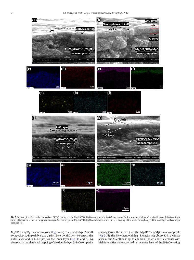
Fig. 3. Cross-section of the (a, b) double-layer Si/ZnO coatings on theMg/HA/TiO2/MgO nanocomposite, (c–i) X-ray map of the fracture morphology of the double-layer Si/ZnO coating inarea 1 of (a); cross-section of the (j, k) monolayer ZnO coating on theMg/HA/TiO2/MgO nanocomposite and (m–s) X-raymap of the fracturemorphology of themonolayer ZnO coating inarea 2 of (j).
34 S.Z. Khalajabadi et al. / Surface & Coatings Technology 277 (2015) 30–43
Mg/HA/TiO2/MgO nanocomposite (Fig. 3m–s). The double-layer Si/ZnOcomposite coating exhibits two distinct layerswith ZnO(~0.6 μm) as theouter layer and Si (~1.1 μm) as the inner layer (Fig. 3a and b). Asobserved in the elemental mapping of the double-layer Si/ZnO composite
coating (from the area 1) on the Mg/HA/TiO2/MgO nanocomposite(Fig. 3c–i), the Si element with high intensity was observed in the innerlayer of the Si/ZnO coating. In addition, the Zn and O elements withhigh intensities were observed in the outer layer of the Si/ZnO coating.

Fig. 5. Potentiodynamic polarization curves of the uncoated Mg/HA/TiO2/MgO nanocom-posite, ZnO-coated and Si/ZnO-coated specimens in the SBF solution.
35S.Z. Khalajabadi et al. / Surface & Coatings Technology 277 (2015) 30–43
Different intensities were observed for theMg, O, P, Ti and Ca elements inthe matrix. The Si layer, which has a columnar structure, and ZnO layerwere easily distinguished in the FESEM images (Fig. 3a and b). Althoughthe samples were severely fractured prior to the FESEM observation, thecoating was still bonded to the nanocomposite substrate. Therefore,good adhesion between the deposited nanostructured coating layersand the Mg/HA/TiO2/MgO nanocomposite substrate was observed dueto more physical interfacial interactions between nano-particles andsubstrate than that of micron-size particles.
A combination of TEM and selected area electron diffraction (SAED)patterns was used for additional structural and crystallographic charac-terization of the Si/ZnO coating. As shown in Fig. 4a, the particles of theSi/ZnO coating that were carefully removed from the outer layer of thecoated Si/ZnO-sample are nearly spherical in shape with a narrow sizedistribution and average diameter of ~36 nm. A ring pattern consistingof sharp spots was observed in the SAED pattern of the Si/ZnO coating.The polycrystalline growth of the Si/ZnO coating was confirmed by thepresence of rings in the SAED pattern. However, the sharp bright spotsmay be due to the individual formation of larger nanoparticles withspecific lattice planes (Fig. 4b). The calculated d-values using the SAEDpattern indicated that the diffraction rings of the Si/ZnO-coating exhib-ited Debye–Scherrer rings corresponding to the (100), (002), (101),(102), (110), (103), (200), (112), (201), (004) and (202) planes ofZnO. The corresponding d-values for the (100) and (002) planes ofhexagonal ZnO (with lattice parameters as a = b = 3.24982 Å andc = 5.20661 Å) was calculated to be 2.832 Å and 2.568 Å, respectively.As regards the calculated d-values and SAED patterns, some of thediffractions of cubic silicon were observed in the SAED patterns of theSi/ZnO-coating (Fig. 4b). For the Si coating, the calculated d-values are3.145 Å and 1.951 Å, which correspond to the (1 1 1) and (2 2 0) planesof cubic silicon with a lattice parameter of a = 5.43 Å.
3.2. Electrochemical and immersion measurements
The cathodic and anodic polarization curves of the uncoatedMg/HA/TiO2/MgO nanocomposite as well as nano-ZnO and nano-Si/ZnO coatedspecimens are shown in Fig. 5. Hydrogen evolution via water reductionis typically evaluated by cathodic polarization curves. However, thedissolution of Mg was evaluated using anodic polarization curves [46].The cathodic reaction of the uncoated sample exhibited faster kineticscompared with the ZnO- and Si/ZnO-coated samples. This result indi-cates that hydrogen evolution is more kinetically difficult in the coatedsamples. At the beginning of the anodic polarization, the anodic currentdensity of the uncoated sample sharply increased and quickly reached alimiting current density of ~0.01 mA/cm2, which was controlled bythe diffusion and/or dissolution of magnesium ions. This high currentdensity indicates that the uncoated Mg/HA/TiO2/MgO nanocompositesuffered from severe corrosion in the SBF solution. A nobler corrosion
Fig. 4. TEM micrographs (a) and (b) selected area electr
potential and lower corrosion current density were detected for themonolayer ZnO and double-layer Si/ZnO-coated samples comparedwith the uncoated sample. This result shows the positive effect of thecoating on the inhibitive properties of the Mg/HA/TiO2/MgO nanocom-posite. The anodic polarization curve of the Si/ZnO coated sample exhib-ited two passivation regions. The first region of passivation was relatedto the presence the ZnO layer, which had a compact and uniform mor-phology that acted as a protective coating increasing the corrosion resis-tance of the Si/ZnO-coated specimen. The breakdown on the anodicpolarization curve of the Si/ZnO-coated sample and an increase in itscorrosion current density in a constant applied potential were relatedto the ZnO layer breaking during the electrochemical test. However,the presence of the Si layer coating on the Mg/HA/TiO2/MgO nanocom-posite, which acted as a sub-layer, caused a region of repassivation. Thepassive region on the anodic polarization curve of the ZnO-coatedsample corresponded to the ZnO coating. The following equation wasused to calculate the polarization resistance (RP) of samples with theelectrochemical parameters (i.e., icorr, βa and βc) [14,23]:
RP ¼ βa � βc= 2:3 βaþ βcð Þicorrð Þ: ð1Þ
The RP value of the double-layer Si/ZnO coating (Table 1) increasedcompared with that of the monolayer ZnO coating and uncoatedsamples, which indicates improvement of the protective properties ofthe Si/ZnO coating in an aggressive solution. The corrosion rate (Pi)
on diffraction (SAED) of the Si/ZnO coated sample.

Table 1Electrochemical parameters of the uncoated Mg/HA/TiO2/MgO nanocomposite as well as the ZnO-coated and Si/ZnO-coated samples in the SBF solution from the polarization test.
Sample Corrosion potential, Ecorr(mV vs. SCE)
Current density, icorr(μA/cm2)
Cathodic slope, βc(mV/decade) vs. SCE
Anodic slope, βa(mV/decade) vs. SCE
Polarization resistance,RP (kΩ cm2)
Corrosion rate, Pi(mm/year)
Uncoated Mg-HA −1417 ± 21 255 ± 8.1 280 ± 13.9 119 ± 7.2 0.14 ± 0.04 5.82 ± 0.26Nano-ZnO coated −1132 ± 11 53.82 ± 3.6 242 ± 7.3 531 ± 10.3 1.34 ± 0.51 1.23 ± 0.11Nano-ZnO/Si coated −1023 ± 14 11.34 ± 0.74 69 ± 1.6 2032 ± 14.7 2.55 ± 0.85 0.25 ± 0.01
36 S.Z. Khalajabadi et al. / Surface & Coatings Technology 277 (2015) 30–43
was calculated by Faraday's law [14,23] using the corrosion currentdensity (icorr (mA/cm2)) in the following equation:
Pi ¼ 22:85icorr: ð2Þ
Even a monolayer ZnO coating provides a lower corrosion rate thanthe uncoated sample. Table 1 lists the corrosion current density (icorr),corrosion potential (Ecorr, VSCE), cathodic Tafel slopes (βc), anodicTafel slopes (βa) and corresponding corrosion rate (Pi) of the speci-mens, which were extracted from the polarization curves. Fig. 6 showsthe hydrogen evolution volume of the uncoated and coated specimensas a function of the immersion time. The degradation rate, whichwas calculated using the released hydrogen volume, of the ZnO-(2.17 ml/cm2/day) and Si/ZnO-coated (1.07 ml/cm2/day) samples de-creased compared with that of the uncoated sample (4.42 ml/cm2/day)during the entire immersion time in the SBF (168 h). Therefore, theSi/ZnO composite coating exhibited the lowest hydrogen evolutionrate, which indicates that the Si/ZnO composite coating exhibits betterprotection than the monolayer ZnO coating. This result may be due tothe greater chemical stability of the Si/ZnO coating in the SBF as wellas the effective role of Si as a sub-layer to decrease the degradation rate.
As reported in recent studies, grain refinement into nano-scaleregime and surface roughness play important roles in the corrosionresistance of the coated samples [47]. With decrease in the size of parti-cles that formed the coating layers from micro-meter to nano-meterscale, the surface area between the particles of coating was increasedthat decreased the diffusion paths. As a result, the lower amount ofcorrosive solution can penetrate to the substrate of sample. Therefore,the corrosion resistance and mechanical integrity of nano-coatedsamples improved in comparison to those of the coated samples withmicron-size particles. Fig. 7 indicates the correlation between the sur-face energy and corrosion rate of uncoated and coated samples. Accord-ing to Fig. 7, the surface energy of nano-ZnO and nano-Si/ZnO coatedsamples indicated smaller values than that of the uncoated sample. Asreported by Song and Xu [48], the electrochemical dissolution rate ofAZ31 Mg alloy decreased by decreasing of the surface energy value.Yong et al. have also reported that the activation energy of corrosionwas gained by the surface energy of samples [49]. Therefore, decreasein the surface energy value of nano-ZnO and nano-Si/ZnO coated
Fig. 6.Hydrogen evolution of the uncoatedMg/HA/TiO2/MgO nanocomposite, ZnO-coatedand Si/ZnO-coated specimens in the SBF solution.
samples compared to the uncoated sample can be a reason to decreaseof the corrosion rate and hydrogen evolution rate of coated samples.Additionally, the reduce in surface free energy andwettability of amag-nesium alloy to improve corrosion behavior have been performed byplating of the polymeric nanofilms on the sample surface [50].
In addition to the corrosion prevention and HA forming ability [51],nanoporous coatings with a large surface area can also provide a drugreservoir to control drug release and enhance osteoblast adhesion thatincrease biocompatibility of Mg-based biomedical implants as a drugcarrier. Sustained drug release is essential in preventing an inflamma-tion response and reducing late restenosis. It has been shown thatporosity and size had effects on the drug release mechanisms ofPLGA [52]. Nano porosities in coating layers facilitate the mechan-ical interlocking of the cells with the surface, thereby favoringosseointegration process. Porosity also favors osseointegration andensures more contact surface that providing the pathways for thepermeation of cell nutrition [18].
As observed in Fig. 8, the uncoated sample was corroded withremarkable corrosion products and suffered from peeling, corrosionpits and deep cracks (Fig. 8a and b). The ZnO-coated sample exhibitedfewer corrosion products, pits and deep cracks than the uncoatedsample even though the coating layers of the corrosion products (withbright color) peeled off in some areas due to hydrogen evolution andcorrosion, which resulted in the dark appearance of the substrate.However, the corrosion pits and deep cracks mostly disappeared inthe Si/ZnO-coated sample, and the amount of peeling decreased com-pared with the monolayer ZnO coating and uncoated samples. The Si/ZnO composite coating maintained its integrity after 168 h of immer-sion in the SBF, which prevented additional corrosive solution frompenetrating the substrate. Therefore, the degradation rate decreased.The Si/ZnO composite coating protected the substrate better than theZnO coating, which is most likely due to various factors, such as compo-sition, roughness, compactness, morphology, and wettability. The EDSresults of the uncoated Mg/HA/TiO2/MgO nanocomposite as well asthe ZnO- and Si/ZnO-coated samples after 168 h of immersion in theSBF solution are shown in Fig. 8. The corrosion products were primarilycomposed of O, P, Mg and Ca. The atomic ratio of Ca to P (Ca/P) was
Fig. 7. The surface energy of uncoatedMg/HA/TiO2/MgOnanocomposite, ZnO-coated, and Si/ZnO-coated samples versus the corrosion rate and hydrogen evolution rate of the samples.

Fig. 8. FESEMmicrographs of (a, b) the uncoated Mg/HA/TiO2/MgO nanocomposite, (d, e) ZnO-coated, and (g, h) Si/ZnO-coated specimens after 168 h of immersion in a SBF solution at37 °C. EDS analyses of (c) area 1 in (a), (f) area 2 in (d), and (k) area 3 in (g).
Fig. 9. XRD patterns of the uncoated Mg/HA/TiO2/MgO nanocomposite, Si-coated, and Si/ZnO-coated samples after 168 h of immersion in a SBF solution at 37 °C.
37S.Z. Khalajabadi et al. / Surface & Coatings Technology 277 (2015) 30–43
approximately 1.72 in the uncoated sample, which is close to 1.67 (theCa/P atomic ratio of HA) [16] and suggested the precipitation ofa compound containing Ca and P elements. The Ca/P atomic ratio(i.e., 1.52–2.0) of the calcium phosphate compound depended on thein vitro degradation time and material composition. The formation ofthe calcium phosphate compound indicated that the composite exhibit-ed good osteoinductivity and osteoconductivity [5,8]. O, P, Mg, Ca, andZn elements were detected by EDS analysis in the corrosion productsof the ZnO-coated sample. However, in addition to these elements, Siwas also observed in the corrosion products of the Si/ZnO-coatedsample. The presence of Si and Zn in the EDS results of the corrosionproducts is related to the coating layers. The Ca/P atomic ratio of thecorrosion products formed on the ZnO- and Si/ZnO-coated samplesafter 168 h of immersion in the SBF solution was 1.63 and 1.54, respec-tively, which indicated HA precipitation on the ZnO- and Si/ZnO-coatedsamples. Therefore, HA precipitated on the surface of the immersedsamples (Fig. 8).
Fig. 9 shows the phase analysis of the corrosion products based onthe X-ray diffraction patterns of the uncoated, ZnO- and Si/ZnO-coatedsamples after 168 h immersion at 37 °C in the SBF solution. By compar-ing the X-ray diffraction patterns of the samples before and afterimmersion, the number and intensity of XRD peaks of the Mg(OH)2and HA phases increased after 168 h of immersion in the SBF solution.The immersion of specimens caused the Mg and MgO components ofthe samples to react with the SBF solution. Therefore, Mg(OH)2 formson the sample surface according to reactions 3 and 4 [14]:
Mg þ 2H2O→MgðOHÞ2 þ H2↑ ð3Þ
MgO þ H2O→MgðOHÞ2 ð4Þ
Due to direct exposure of the uncoatedMg/HA/TiO2/MgO nanocom-posite to the corrosive solution, reactions (3) and (4) were intensified,and a higher volume of H2 was released from the uncoated samplecompared with the ZnO- and Si/ZnO-coated samples. Therefore, thehighest degradation rate was observed for the uncoated Mg/HA/TiO2/MgO nanocomposite (Fig. 6). In addition, according to the X-ray diffrac-tion pattern of the immersed samples, a higher amount ofMg(OH)2wasformed on the uncoated sample compared with the ZnO- and Si/ZnO-

38 S.Z. Khalajabadi et al. / Surface & Coatings Technology 277 (2015) 30–43
coated samples. However, after 168 h of soaking the samples in the SBFsolution, the chloride ions (Cl−) of the SBF solution would react withMg(OH)2 to form a more soluble MgCl2 (reaction (5)). Therefore, theMg(OH)2 films were destroyed, which exposed fresh substrate to thecorrosive solution [14].
MgðOHÞ2 þ 2Cl−→MgCl2 þ 2OH− ð5ÞHowever, the use of HCL in the buffer inevitably raises the chloride
content as well as chloride containing buffer gives a corrosion ratehigher than normal corrosion rate. Thus, according to the recent studies,the non-chloride containing buffer ismore desirable for immersion test-ing of Mg-based implants [53]. The presence of phosphate ions (HPO4
2−
or PO43−) and Ca2+ in the SBF solution and the reaction of these ions
with OH− ions resulted in the formation of HA on the surface of thespecimens after different immersion times according to reaction (6)[14]:
10Ca2þ þ 8OH− þ 6HPO2−4 →Ca10ðPO4Þ6ðOHÞ2 þ 6H2O ð6Þ
A higher amount of OH− was released from the uncoated samplecompared with the ZnO- and Si/ZnO-coated samples due to the pres-ence of a larger amount of Mg(OH)2, which resulted in the formationof more HA on the uncoated sample based on the XRD patterns of theimmersed sample.
The corrosion mechanism of the double-layered Si/ZnO compositecoated Mg/HA/TiO2/MgO nanocomposites is schematically illustratedin Fig. 10 that can be summarized as follows: firstly, the ZnO layer, asan outer protective layer on the Mg/HA/TiO2/MgO nanocomposites,contacts the SBF solution. Although the ZnO layer is uniform and homo-geneously covers the Si layer, it is generally porous, and the SBF solutioncan still reach to the Si layer through the pores and flaws of the ZnOfilm(Fig. 10a). At the next stage a corrosive electrolyte already occupied theporous outer layer, introduced new defects (big deep pores and cracks)and enlarged the existing ones, while the inner Si layer consisting poresis still intact. Further increase in immersion time caused the ZnO filmbegan to degrade and experienced destruction, and porosities of Sifilm as the second line of protective layers were filled with the electro-lyte (Fig. 10b). However, this layer can protect the Mg/HA/TiO2/MgOnanocomposites for limit duration owing to its thickness then graduallydissociated in the electrolyte, thusmore solution begins to interact with
Fig. 10. Schematic illustration of the degradation mechanism of t
the Mg-based composite directly. As the Mg/HA/TiO2/MgO nanocom-posites starts to degrade, Mg(OH)2 starts forming at the coating inter-face with the substrate and SBF solution. Then, HA starts forming onthe outer surface as reported, the formation ofMg(OH)2 andHAprovid-ing further protection of sample from corrosive solution (Fig. 10c).Deposition of more amount of Mg(OH)2 and HA on the outer surfaceof samples caused the formation and enlargement of the defects beslow down at this stage (Fig. 10d). Eventually, some fragments of coat-ing layers and corrosion products peeled off by corrosion attacks andhydrogen evolution and the substrate under the coating are exposedto the SBF solution (Fig. 10e). This explains the higher corrosion resis-tance achieved and corrosion attack delayed by the Si/ZnO coating onthe surface of Mg/HA/TiO2/MgO nanocomposites. According to the elec-trochemical and immersion tests, the dense and homogenous nano-Si/ZnO coatings produced with uniform particle size effectively protectedthe Mg-based composite from corrosion attacks. Table 2 summarizedand compared the corrosion behavior and hydrogen evolution volumeof somemagnesium-based alloys that coated by different types of coat-ings using physical vapor deposition (PVD), electrochemical deposition(ED), plasma enhanced chemical vapor deposition (PECVD), plasma ionimplantation, manual brushing, phosphating bath and sol–gel tech-niques. As seen, a nobler corrosion potential and lower corrosion cur-rent density was detected for double-layer Si/ZnO coated Mg/HA/TiO2/MgO nanocomposites compared to those of the MgTiO3/CaTiO3/Mg3(PO4)2 coated nanocomposite [14] that indicates the higher corro-sion resistance of Si/ZnO coating. As seen in Table 2, the corrosion rateof the Si coated Mg–Y–RE alloy [29] and Si/TiO2 coated Mg–Ca alloy[44] is higher than that of Si/ZnO coated nanocomposite; however, Si/HA coating on the Mg–Zn–Mn–Ca alloy showed the lower corrosionrate compared to Si/ZnO coating [23]. Additionally, nano-Si/ZnO coatingon the Mg/HA/TiO2/MgO nanocomposite indicates higher corrosionresistance in comparison to the silicon [29], Mg-rich epoxy (reinforcedby ZnO particles) [32] and Zinc phosphate [54] coatings on the Mg–Y–RE and AZ91D alloys, respectively. After 168 h of immersion in SBF solu-tion, the hydrogen evolution volume of Si/ZnO, Si/HA and Si/TiO2 coatedsamples is 6, 10 and 11 ml/cm2; however, this value calculated 1.3 and1.5 ml/cm2 for WE43 alloy that coated by SiC [30] and silicon [28] coat-ings, respectively.
FTIR spectroscopy was used to characterize the carefully removedcorrosion products that formed on the surface of the uncoated, ZnO-
he double-layered Si/ZnO composite coating in SBF solution.
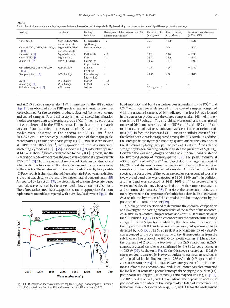
Table 2Electrochemical parameters and hydrogen evolution volume of some biodegradable Mg-based alloys and composites coated by different protective coatings.
Coating Substrate Coatingtechnique
Hydrogen evolution volume after 168h immersion (ml/cm2)
Corrosion rate(mm/year)
Current density,icorr (μA/cm2)
Corrosion potential, Ecorr(mV vs. SCE)
Nano-ZnO/Si Mg/HA/TiO2/MgOnanocomposite
RF magnetronsputtering
~6 0.25 11.34 −1023
Nano-MgTiO3/CaTiO3/Mg3(PO4)2[10]
Mg/HA/TiO2/MgOnanocomposite
Post-annealing – 4.6 204 −1339
Nano-Si/HA [9] Mg–Zn–Mn–Ca PVD + ED ~10 0.12 5.65 −1530Nano-Si/TiO2 [8] Mg–Ca alloy PVD ~11 0.57 25.2 −1539Silicon (Si) [14] Mg–Y–RE alloy Plasma ion
implantation– ~0.62 ~27 −1890
Mg-rich epoxy primer + ZnO[15]
AZ91D alloy manualbrushing
– ~1.3 ~60 −1480
Zinc phosphate [16] AZ91D alloy Phosphatingbath + ZnO
– ~0.46 ~20 −1180
SiC [17] WE43 alloy PECVD ~1.3 – – –Silicon (Si) [18] WE43 alloy PECVD ~1.5 – – –58S bioactive glass [19] AZ31 alloy Sol–gel – 0.7 mg cm−2
d−1
– –
39S.Z. Khalajabadi et al. / Surface & Coatings Technology 277 (2015) 30–43
and Si/ZnO-coated samples after 168 h immersion in the SBF solution(Fig. 11). As observed in the FTIR spectra, similar chemical structureswere obtained for the corrosion products obtained from the uncoatedand coated samples. Four distinct asymmetrical stretching vibrationmodes corresponding to phosphate group (PO4
3−) (i.e., υ1, υ2, υ3, andυ4) were detected in the FTIR spectra. The peak at approximately963 cm−1 corresponded to the υ1 mode of PO4
3−, and the υ2 and υ4
modes were observed in the spectra at 488–431 cm−1 and603–577 cm−1, respectively. In addition, some of the major peakscorresponding to the phosphate group (PO4
3−), which were locatedat 1099 and 1050 cm−1, corresponded to the asymmetricalstretching υ3 mode of PO4
3− [55]. As shown in Fig. 9, a doublet appearedat 1425–1459 cm−1,which corresponded to theυ3 (CO3
2−)mode, and theυ2 vibrationmode of the carbonate groupwas observed at approximately877 cm−1 [55]. The diffusion and dissolution of CO2 from the atmosphereinto the HA structure can result in the appearance of the carbonate groupin the spectra. The in vitro resorption rate of carbonated hydroxyapatite(CHA), which is higher than that of free carbonate HA powders, exhibiteda rate that was closer to the resorption rate of natural boneminerals [56].As reported by Lala et al. [57], the bioactivity of calcium phosphate-basedmaterials was enhanced by the presence of a low amount of CO3
2− ions.Therefore, carbonated hydroxyapatite is more appropriate for bonereplacement materials compared with pure HA. As shown in Fig. 11, the
Fig. 11. FTIR absorption spectra of uncoated Mg/HA/TiO2/MgO nanocomposite, Si-coated,and Si/ZnO-coated samples after 168 h of immersion in a SBF solution at 37 °C.
band intensity and band resolution corresponding to the PO43− and
CO32− vibration modes decreased in the coated samples compared
with the uncoated sample, which indicated that less HA was formedin the corrosion products on the coated samples after 168 h of immer-sion in the SBF solution. The stretching, vibrational and translationalmodes of OH− ions were located at ~3698 cm−1 and ~637 cm−1 dueto the presence of hydroxyapatite and Mg(OH)2 in the corrosion prod-ucts [58]. In fact, the immersed OH− ions in an infinite chain of OH−
that led to both vibrations appeared among the FTIR bands. In addition,the strength of the hydrogen bonding system affects the vibrations ofthe structural hydroxyl groups. The peak at 3698 cm−1 was due tostronger hydrogen bonding, which indicates the presence of Mg(OH)2.However, the weaker hydrogen bonding at ~637 cm−1 was related tothe hydroxyl group of hydroxyapatite [58]. The peak intensity at~3698 cm−1 and ~637 cm−1 increased due to a larger amount ofMg(OH)2 and HA being formed as corrosion products on the uncoatedsample compared with the coated samples. As observed in the FTIRspectra, the adsorption of the water molecules corresponded to a rela-tively broad band that was detected at 3300–3800 cm−1. In addition,another band was detected at 1648–1668 cm−1 corresponding towater molecules that may be absorbed during the sample preparationand/or immersion process [58]. Therefore, the corrosion products aremore hydrated in the presence of chloride ions than in distilled water.As a result, the hydration of the corrosion product may occur by thepresence of Cl− ions in the SBF [59].
XPS analysis was performed to determine the chemical compositionand investigate the coating characteristics of the surface of the uncoated,ZnO- and Si/ZnO-coated samples before and after 168 h of immersion inthe SBF solution (Fig. 12). Each element exhibits the characteristic bindingenergy in the XPS spectra. In addition, the elemental information inthe uppermost ~100 Å surface layers of an analyzed specimen can bedetected by XPS [60]. The Si 2p peak at a binding energy of ~98.9 eVcorresponded to the presence of some of the Si nanoparticles from thesub-layer on the surface of the Si/ZnO-composite coating [61]. In addition,the presence of ZnO on the top layer of the ZnO-coated and Si/ZnO-composite coated samples was confirmed by the Zn 2p peak located at~1035 eV [62]. As shown in Fig. 12, the O1s spectra located at ~532.6 eVcorresponded to zinc oxide. However, surface contamination resulted ina C 1s peak with a binding energy at ~286 eV in the XPS spectra of theZnO-coated sample [63]. The obtainedXPS survey spectra from the outer-most surface of the uncoated, ZnO- and Si/ZnO-coated samples immersedfor 168 h in SBF contained photoelectron peaks belonging to calcium (Ca),phosphorus (P), oxygen (O), carbon (C) and magnesium (Mg) (Fig. 13).The XPS spectra of Ca, P, and O may indicate the deposition of calciumphosphate on the surface of the samples after 168 h of immersion. Thehigh-resolution XPS spectra of Ca 2p, P 2p, and O 1s for the as-deposited

Fig. 12. Survey XPS spectra of the uncoatedMg/HA/TiO2/MgO nanocomposite, ZnO-coated,and Si/ZnO-coated samples.
40 S.Z. Khalajabadi et al. / Surface & Coatings Technology 277 (2015) 30–43
corrosion products on the samples immersed for 168 h are shown inFig. 14. As shown in Fig. 14a, the Ca 2p spectrum was deconvoluted intotwo peaks consisting of Ca 2p1/2 and Ca 2p3/2 at binding energies of~351 eV and ~347 eV, respectively. The P 2p spectrum (Fig. 14c) wasdeconvoluted into two peaks (i.e., P 2p1/2 peak at ~134 eV and P 2p3/2peak at ~133 eV). In addition, the O 1s peak (Fig. 14b) was deconvolutedinto three peaks as follows: the O 1s signal at a binding energy of ~531 eVcorresponded to the phosphate (PO4
3−) groups and the spectrum at~533 eV was assigned to the hydroxyl (\\OH) groups [60]. The spectraat ~532 eV corresponded to the carbonate (CO3
2−) group where thespectral intensity increased in the coated samples compared with theuncoated sample due to carbon contamination during the preparationprocess. The binding energies of the Ca 2p, P 2p, and O 1s peaks in theXPS spectra of the immersed samples are in good agreement with thoseof the Ca 2p, P 2p, and O 1s peaks for hydroxyapatite [60]. A decrease inthe spectral intensity of the Ca 2p, P 2p, and O 1s peaks was observedfor the coated samples compared with the uncoated sample, which maybe due to the formation of a smaller amount of corrosion products, such
Fig. 13. Survey XPS spectra of the uncoated Mg/HA/TiO2/MgO nanocomposite, ZnO-coated,and Si/ZnO-coated samples after 168 h of immersion in a SBF solution at 37 °C.
as Mg(OH)2 and hydroxyapatite, in the coated samples after 168 h ofimmersion in the SBF solution. In addition, the intensity of the Ca 2p, P2p, and O 1s XPS spectra of the ZnO-coated sample indicated smalleramounts compared with that of the Si/ZnO-coated sample.
The Mg 2p spectrum, which has a binding energy of ~49.5 eV andcorresponds to Mg(OH)2, appeared in the XPS spectra of the corrosionproducts from the samples [60]. In recent studies, the intensity of theXPS spectra was used to calculate the atomic concentrations of theelements. As shown in Fig. 13, the spectral intensity of the Mg 2p peakat 49.5 eV, which corresponds to Mg(OH)2, indicates a larger amountin the uncoated sample compared with that in the ZnO- and Si/ZnO-coated samples. Therefore, moreMg(OH)2 was formed on the uncoatedMg/HA/TiO2/MgO nanocomposite after 168 h of immersion in SBF. Theexistence of a larger amount of Mg(OH)2 in the corrosion productsindicates a severe pitting type of corrosion. In addition, the intensity ofthe Mg 2p spectra indicates a smaller amount in the Si/ZnO-coatedsample compared with that in the ZnO-coated sample, which indicatesmore severe corrosion occurred in the ZnO-coated sample. The C 1sspectrum with a binding energy of ~286 eV in the XPS spectra may bedue to the existence of carbonate ions (CO3
2−) in the HA phase [64].Since natural bone is composed of nanostructured hydroxyapatite,
using the nanostructured bioceramic as the protective coatings with acomparatively big specific surface area induced the precipitation ofMg2+, Ca2+ and PO4
3− ions more effectively in comparison to theother traditional coatings consisting micro-scale particles [65]. As aresult, the nanostructured coatings would better mimic the structure ofthe bone that intensified in vivo HA forming ability and improved thebioactivity and osteoconductivity of Mg-based implants for biomedicalapplications. High surface area of nanomaterials provides additionalavailable sites for protein adsorption and thereby enhancing the cell/material interaction. In addition to the dimensional effects ofnanomaterials, possible surface chemical changes by nanostructuringcan significantly affect the cell/biomaterial interaction [51]. As reportedby Fathi et al., after 4 days of immersion in SBF solution, the numerousuniform wormlike HA crystallites (80–100 nm in length) with a Ca/Pratio of 1.63 that formed on the nanostructured bredigite powdersconfirmed the superior in vitro HA forming ability of the nanostructuredbredigite compared to that of the coarse grained bredigite powders. Tinyspherical Ca–P particles with crystallite sizes of around 400–500 nmwere observed on the surface layer of forsterite nanopowders thatwere transformed to clusters of agglomerated HA after 28 days ofimmersion in SBF solution [66]. At the recent studies, developments inbiomineralization have already been demonstrated that nanosized crys-tals and particles play an important role in the formation of hard tissuesof animals [67].
3.3. Mechanical properties
Fig. 15 shows the compressive stress–strain curves of the uncoated,ZnO, and Si/ZnO coated specimens before and after immersion in SBFfor 28 days. The compressive strength and elongation of uncoated nano-composite before immersion were ~253 MPa and ~9.8% that thesevalues significantly decreased to ~104 MPa and ~5.3%, respectively,after 28 days of immersion in SBF. However, the compressive strengthof the Si/ZnO, and ZnO coated sample was obtained ~148 MPa and~116 MPa, as well as the elongation percentage showed ~6.7% and~7.2% after 28 days of immersion in SBF solution, respectively. Thesevalues are comparable with the compressive strength of human corticalbones (100–230MPa) [13]. As seen in Fig. 15 and Table 3, the synthesisdouble-layered Si/ZnO coating consisting ZnO as a top layer and Si as aninner layer resulted in ~44 MPa and ~2% increase in compressivestrength and elongation of nanocomposite after 28 days of immersioncompared to the uncoated nanocomposite. This phenomenon showedthat the Si/ZnO composite coating leads to a delay of the loss in themechanical properties of the Mg/HA/TiO2/MgO nanocomposite. Due tothe protective effect of the coatings, the compressive strength of the

Fig. 14.Detailed XPS spectra of the elements of the uncoatedMg/HA/TiO2/MgO nanocomposite, ZnO-coated, and Si/ZnO-coated samples after 168 h of immersion in a SBF solution at 37 °C.
41S.Z. Khalajabadi et al. / Surface & Coatings Technology 277 (2015) 30–43
samples with double-layered Si/ZnO coating after 28 days of immersionis much higher than that of the ZnO-coated sample.
However, the single layered ZnO coated sample shows higher degra-dation rates compared to the double-layered Si/ZnO coated samplebecause the single layered ZnO coating broke easier and the barriereffect was lost resulting in the diffusion of SBF in substrate of sample.Thus, Si/ZnO composite coated sample demonstrated the highestcompressive strength and elongation after 28 days of immersion. Thiscan be attributed to the compact and uniform coating with less poresand cracks in the double-layered Si/ZnO coating compared to the ZnOcoating. Hence, the composite coating can effectively delay the declinein compressive strength of the Mg/HA/TiO2/MgO nanocomposite, pro-viding sufficient mechanical integrity and support for post-fracturebone healing.
Fig. 15. Compressive stress–strain curves of the uncoated, ZnO-coated and Si/ZnO-coatedMg/HA/TiO2/MgO nanocomposites before and after 28 days of immersion in SBF solutionat 37 °C.
The post-degradation photographs of uncoated Mg/HA/TiO2/MgOnanocomposite, ZnO and Si/ZnO coated nanocomposites after 28 daysof immersion in SBF solution at 37 °C and following the removal ofcorrosion products by chromic acid are shown in Fig. 16d–f. The assess-ment of these general observations was supported by FE-SEM studiescarried out on the samples, but before the removal of corrosion products(Fig. 16a–c). The uncoated nanocomposite suffered much more severecorrosion (especially in the parts near the edge) than the ZnO and Si/ZnO coated samples in the process of the immersion period, indicatingthat the coatings could provide effective protection for the nanocom-posite substrates. After 28 days of immersion in SBF solution, therewas minor corrosion on the surface of ZnO coating compared to theuncoated nanocomposite, whereas the surface of Si/ZnO coated samplealmost maintained its integrity and nearly kept intact without obviouslocalized corrosion. As seen in Fig. 16a–c, the parts near the edge ofuncoated sample covered by corrosion products and deep cracks; how-ever, lower amount of corrosion products and cracks was observed onedge of ZnO coated sample by 28 days of immersion. The deep cracksalmost disappeared in Si/ZnO coated sample, as well as lowest amountof corrosion products deposited on Si/ZnO coated sample that indicateslower hydrogen evolution rate andhigher corrosion resistance of Si/ZnOcoated sample compared to those of the uncoated and ZnO coatedsamples.
The modulus of elasticity of cortical bone is reported to be about7–30 GPa, the tested magnesium–hydroxyapatite composite seemed
Table 3The ultimate compressive strength and elongation of the uncoated, ZnO-coated andSi/ZnO-coated Mg/HA/TiO2/MgO nanocomposites before and after 28 days of immersionin SBF solution at 37 °C.
Sample Compression strength–UCS(MPa)
Elongation, %
Uncoated sample before 28 daysof immersion
253 ± 11 9.8 ± 0.7
Uncoated sample after 28 daysof immersion
104 ± 6 5.3 ± 0.6
ZnO coated sample after 28 daysof immersion
116 ± 8 7.2 ± 0.7
Si/ZnO coated sample after 28 daysof immersion
148 ± 13 6.7 ± 0.3

Fig. 16. FESEM images of the (a) uncoated, (b) ZnO and (c) Si/ZnO coatedMg/HA/TiO2/MgOnanocomposites after 28 days of immersion. Photographic images of (d) uncoated, (e) ZnO and(f) Si/ZnO coated Mg/HA/TiO2/MgO nanocomposites after 28 days of immersion in SBF solution at 37 °C and following the removal of corrosion products.
42 S.Z. Khalajabadi et al. / Surface & Coatings Technology 277 (2015) 30–43
to be in closer agreement to the characteristics of the natural bone,whose compressive yield strength is 130–180 MPa [13]. While in com-pressive tests, the Mg/HA/TiO2/MgO nanocomposite revealed compres-sive strength of almost double value (~253 MPa) than cortical bone.Moreover, it has been reported that composite materials manufacturedwith HA nanoparticles exhibit a surface with improved osteoblasticactivity and new bone formation, suggesting a clear advantage Mg/HA-based composites in bone tissue applications compared to the vascularstents materials [68]. Since the control of in vivo corrosion is of majorimportance, the use of nano-ZnO and nano-Si/ZnO coatings on Mg/HA/TiO2/MgO provides a wide range of biodegradable magnesium-basedcomposites possessing adjustable corrosion and mechanical propertiesfor load bearing applications in musculoskeletal surgery.
According to the published results, ZnO nanoparticles exhibit anti-bacterial activity since, bacterial contamination is frequently presentin bone defects, antibacterial activity of the material is a crucial factorin treating bone defects and related bacterial infection [36]. Additional-ly, silicon is a biocompatible element which is essential in osteogeniccells. Silicon is also a fundamental element for the growth and develop-ment of the bone, teeth and some invertebrate skeletal parts. It plays acritical role in the bone calcification process [23,44]. Those mechanicalcharacteristics, bio-corrosion properties and bioactivity indicate thatMg/HA/TiO2/MgO nanocomposite coated by nano-ZnO and nano-Si/ZnO layers is more suitable as an orthopedic implant biomaterial (forlarger degradable implants) in load bearing applications than as thevascular stents.
4. Conclusion
In this work, nano-ZnO and nano-Si/ZnO thin films on a Mg/HA/TiO2/MgO nanocomposite were successfully synthesized by RF magne-tron sputtering. Fewer cracks and a smaller amount of pores wereobserved in the Si/ZnOdouble-layer coating comparedwith themonolay-er ZnO-coated sample. The outer layer of the Si/ZnO double-layer coatingwas composed of approximately 72 nm nanospheres that homogenouslycovered the nanocomposite substrate. Based on the potentiodynamicpolarization tests, a lower corrosion rate was calculated for the ZnO-only coated sample than the uncoatedMg/HA/TiO2/MgO nanocomposite.
However, the Si/ZnO-coated sample exhibited the noblest corrosionpotential, the highest polarization resistance (Rp) and the lowest corro-sion rate. The results of the immersion test in SBF at 37 °C indicatedthat the nano-Si/ZnO coating can effectively decrease the rate of hydro-gen evolution from 4.42 ml/cm2/day in the uncoated Mg/HA/TiO2/MgOnanocomposite to 1.07 ml/cm2/day. The degradation rate of Si/ZnO-coated sample exhibited a reduced rate (1.07 ml/cm2/day) comparedwith the ZnO-coated sample (2.25 ml/cm2/day). According to XRD, EDS,FTIR, and XPS analyses, the corrosion products were primarily composedofMg(OH)2, HA and carbonates. However, the formation of HAwasmorefavorable on the Si/ZnO-coated sample compared with the ZnO-coatedsample. The compression tests showed that the nano-Si/ZnO coatingcan delay the loss of the compressive strength and elongation ofthe Mg/HA/TiO2/MgO nanocomposite. These results demonstrated thatsurface treatment of the Mg/HA/TiO2/MgO nanocomposite with a nano-Si/ZnO composite coating can make this nanocomposite suitable for usein biodegradable implants.
Acknowledgments
The first author is a recipient of the International Doctoral Fellow-ship (IDF) scheme fromUniversiti TeknologiMalaysia. This studywasfi-nancially sponsored by the FRGS grants from the Ministry of EducationMalaysia, eScience Fund grants from theMinistry of Science, Technologyand Innovation Malaysia, and UTM Research University grants.
References
[1] F. Witte, J. Fischer, J. Nellesen, H.-A. Crostack, V. Kaese, A. Pisch, F. Beckmann, H.Windhagen, Biomaterials 27 (2006) 1013–1018.
[2] F. Witte, V. Kaese, H. Haferkamp, E. Switzer, A. Meyer-Lindenberg, C.J. Wirth, H.Windhagen, Biomaterials 26 (2005) 3557–3563.
[3] R. Waksman, R. Pakala, P.K. Kuchulakanti, R. Baffour, D. Hellinga, R. Seabron, F.O. Tio,E. Wittchow, S. Hartwig, C. Harder, R. Rohde, B. Heublein, A. Andreae, K.H.Waldmann, A. Haverich, Catheter. Cardiovasc. Interv. 68 (2006) 607–617.
[4] G. Levy, E. Aghion, Acta Biomater. 9 (2013) 8624–8630.[5] M.P. Staiger, A.M. Pietak, J. Huadmai, G. Dias, Biomaterials 27 (2006) 1728–1734.[6] Y. Chen, Z. Xu, C. Smith, J. Sankar, Acta Biomater. 10 (2014) 4561–4573.[7] J. Vormann, Mol. Asp. Med. 24 (2003) 27–37.[8] M.B. Kannan, R.K.S. Raman, Biomaterials 29 (2008) 2306–2314.

43S.Z. Khalajabadi et al. / Surface & Coatings Technology 277 (2015) 30–43
[9] H. Hornberger, S. Virtanen, A.R. Boccaccini, Acta Biomater. 8 (2012) 2442–2455.[10] X. Gu, N. Li, W. Zhou, Y. Zheng, X. Zhao, Q. Cai, L. Ruan, Acta Biomater. 7 (2011)
1880–1889.[11] H.X. Wang, S.K. Guan, X. Wang, C.X. Ren, L.G. Wang, Acta Biomater. 6 (2010)
1743–1748.[12] E. Zhang, L. Yang, J. Xu, H. Chen, Acta Biomater. 6 (2010) 1756–1762.[13] F. Witte, F. Feyerabend, P. Maier, J. Fischer, M. Störmer, C. Blawert, W. Dietzel, N.
Hort, Biomaterials 28 (2007) 2163–2174.[14] S.Z. Khalajabadi, M.R. Abdul Kadir, S. Izman, H.R. Bakhsheshi-Rad, S. Farahany,
Ceram. Int. 40 (2014) 16743–16759.[15] S.Z. Khalajabadi, M.R. Abdul Kadir, S. Izman, M.Z. Mohd Yusop, Appl. Surf. Sci. 324
(2015) 380–392.[16] X.L. Ma, L.H. Dong, X. Wang, Mater. Des. 56 (2014) 305–312.[17] K. Huang, S. Cai, G. Xu, M. Ren, X.Wang, R. Zhang, S. Niu, H. Zhao, Surf. Coat. Technol.
240 (2014) 137–144.[18] P. Amaravathy, S. Sowndarya, S. Sathyanarayanan, N. Rajendran, Surf. Coat. Technol.
244 (2014) 131–141.[19] S.K.F. Asl, S. Nemeth, M.J. Tan, Surf. Coat. Technol. 258 (2014) 931–937.[20] X. Ye, Y. Yang, G. Tang, Surf. Coat. Technol. 258 (2014) 467–484.[21] X. Lu, S.P. Sah, N. Scharnagl, M. Störmer, M. Starykevich, M. Mohedano, C. Blawert,
M.L. Zheludkevich, K.U. Kainer, Surf. Coat. Technol. 269 (2015) 155–169.[22] S. Mohajernia, S. Hejazi, A. Eslami, M. Saremi, Surf. Coat. Technol. 263 (2015) 54–60.[23] H.R. Bakhsheshi-Rad, E. Hamzah, M. Daroonparvar, M.A.M. Yajid, M. Medraj, Surf.
Coat. Technol. 258 (2014) 1090–1099.[24] P. Shi, B. Niu, S.E.Y. Chen, Q. Li, Surf. Coat. Technol. 262 (2015) 26–32.[25] G. Wu, A. Shanaghi, Y. Zhao, X. Zhang, R. Xu, Z. Wu, G. Li, P.K. Chu, Surf. Coat.
Technol. 206 (2012) 4892–4898.[26] A. Balamurugan, A.H.S. Rebelo, A.F. Lemos, J.H.G. Rocha, J.M.G. Ventura, J.M.F.
Ferreira, Dent. Mater. 24 (2008) 1374–1380.[27] X. Qiu, P. Wan, L. Tan, X. Fan, K. Yang, Mater. Sci. Eng. C 36 (2014) 65–76.[28] M. Li, Y. Cheng, Y.F. Zheng, X. Zhang, T.F. Xi, S.C. Wei, Surf. Coat. Technol. 228
(Supplement 1) (2013) S262–S265.[29] M. Jamesh, G. Wu, Y. Zhao, P.K. Chu, Corros. Sci. 69 (2013) 158–163.[30] M. Li, Y. Cheng, Y.F. Zheng, X. Zhang, T.F. Xi, S.C. Wei, Appl. Surf. Sci. 258 (2012)
3074–3081.[31] G.J. Wan, P. Yang, X.J. Shi, M. Wong, H.F. Zhou, N. Huang, P.K. Chu, Surf. Coat.
Technol. 200 (2005) 1945–1949.[32] S. Shen, Y. Zuo, Corros. Sci. 87 (2014) 167–178.[33] S. Pommiers, J. Frayret, A. Castetbon, M. Potin-Gautier, Corros. Sci. 84 (2014)
135–146.[34] H. Chen, C.P. Chen, C.-T.R. Yu, Y.T. Chen, C.-C. Teng, K.-Y. Lo, C.H. Lin, B.-Y. Huang,
Appl. Surf. Sci. 311 (2014) 422–425.[35] C.L. Chu, Z.H. Liu, X. Rao, Q. Sun, P.H. Lin, F. Chen, P.K. Chu, Surf. Coat. Technol. 232
(2013) 68–74.[36] A.C. Jayasuriya, A. Aryaei, A.H. Jayatissa, Mater. Sci. Eng. C 33 (2013) 3688–3696.[37] B. Fang, C. Zhang, G. Wang, M. Wang, Y. Ji, Sensors Actuators B Chem. 155 (2011)
304–310.[38] C. Lan, B. Lin, Y. Jiang, C. Li, Mater. Lett. 132 (2014) 116–118.
[39] P. Sundara Venkatesh, C.L. Dong, C.L. Chen, W.F. Pong, K. Asokan, K. Jeganathan,Mater. Lett. 116 (2014) 206–208.
[40] G.G. Wang, J. Zeng, J.C. Han, L.Y. Wang, Mater. Lett. 137 (2014) 307–310.[41] Y. Cai, N. Wu, Q.Wei, K. Zhang, Q. Xu, W. Gao, L. Song, Y. Hu, Surf. Coat. Technol. 203
(2008) 264–270.[42] T. Kokubo, H. Takadama, Biomaterials 27 (2006) 2907–2915.[43] A. Sudholz, K. Gusieva, X. Chen, B. Muddle, M. Gibson, N. Birbilis, Corros. Sci. 53
(2011) 2277–2282.[44] H. Bakhsheshi-Rad, E. Hamzah, M. Daroonparvar, M. Kasiri-Asgarani, M. Medraj,
Ceram. Int. 40 (2014) 14009–14018.[45] A. Srinivasan, P. Ranjani, N. Rajendran, Electrochim. Acta 88 (2013) 310–321.[46] Z. Li, X. Gu, S. Lou, Y. Zheng, Biomaterials 29 (2008) 1329–1344.[47] M. Laleh, F. Kargar, J. Alloys Compd. 509 (2011) 9150–9156.[48] G.-L. Song, Z. Xu, Corros. Sci. 54 (2012) 97–105.[49] Y. Pan, Y.C. Zhou, Z.F. Zhou, Y.L. Huang, Y.G. Liao, C.Q. Sun, Trans. Nonferrous Metals
Soc. 17 (2007) 1225–1229.[50] Z. Kang, X. Lai, J. Sang, Y. Li, Thin Solid Films 520 (2011) 800–806.[51] A. Simchi, E. Tamjid, F. Pishbin, A.R. Boccaccini, Nanomed. Nanotechnol. 7 (2011)
22–39.[52] J. Ma, M. Thompson, N. Zhao, D. Zhu, J. Orthop. Trans. 2 (2014) 118–130.[53] W.F. Ng, M.H. Wong, F.T. Cheng, Surf. Coat. Technol. 204 (2010) 1823–1830.[54] G.Y. Li, J.S. Lian, L.Y. Niu, Z.H. Jiang, Q. Jiang, Surf. Coat. Technol. 201 (2006)
1814–1820.[55] M. Kheradmandfard, M.H. Fathi, Ceram. Int. 39 (2013) 1651–1658.[56] B. Nasiri-Tabrizi, A. Fahami, R. Ebrahimi-Kahrizsangi, Ceram. Int. 40 (2014)
901–910.[57] S. Lala, S. Brahmachari, P.K. Das, D. Das, T. Kar, S.K. Pradhan, Mater. Sci. Eng. C 42
(2014) 647–656.[58] M. Kheradmandfard, M.H. Fathi, M. Ahangarian, E.M. Zahrani, Ceram. Int. 38 (2012)
169–175.[59] M.I. Jamesh, G. Wu, Y. Zhao, D.R. McKenzie, M.M.M. Bilek, P.K. Chu, Corros. Sci. 82
(2014) 7–26.[60] H. Wang, S. Zhu, L. Wang, Y. Feng, X. Ma, S. Guan, Appl. Surf. Sci. 307 (2014) 92–100.[61] M. Li, Y. Cheng, Y. Zheng, X. Zhang, T. Xi, S. Wei, Surf. Coat. Technol. 228 (2013)
S262–S265.[62] C. Wagner, W. Riggs, L. Davis, J. Moulder, G. Muilenberg, Handbook of X-ray
Photoelectron Spectroscopy, Perkin-Elmer, Eden Prairie, MN, 1979.[63] K. Jeeva Jothi, K. Palanivelu, Appl. Surf. Sci. 288 (2014) 60–68.[64] A. Abdal-hay, P. Vanegas, A.S. Hamdy, F.B. Engel, J.H. Lim, Chem. Eng. J. 254 (2014)
612–622.[65] G. Wu, J.M. Ibrahim, P.K. Chu, Surf. Coat. Technol. 233 (2013) 2–12.[66] M. Diba, O.-M. Goudouri, F. Tapia, A.R. Boccaccini, Curr. Opin. Solid State Mater. 18
(2014) 147–167.[67] J.H. Gao, S.K. Guan, J. Chen, L.G. Wang, S.J. Zhu, J.H. Hu, Z.W. Ren, Appl. Surf. Sci. 257
(2011) 2231–2237.[68] W. Cui, E. Beniash, E. Gawalt, Z. Xu, C. Sfeir, Acta Biomater. 9 (2013) 8650–8659.