surface auger mining at rietspruit mine services (pty) ltd
TRANSCRIPT

▲115The Journal of The South African Institute of Mining and Metallurgy MARCH 2002
Introduction
Rietspruit Mine Services Proprietary Limited isa joint venture between Ingwe CoalCorporation and Duiker Mining Limited and isproducing approximately 600 000 run-of-minetonnes. Rietspruit Mine services ProprietaryLimited is situated near Kriel in theMpumalanga Province and was originallyestablished as an opencast mine in 1976. As aresult of increase in depth and stripping ratio itwas decided to start underground operationsin 1991.
Three separate opencast pits were mined,the layout and configuration of these pitsresulted in the construction of a number ofpermanent ramps and haul roads that wereconstructed to be used until the end of life ofthe mine.
The combination of opencast andunderground mining meant that portions ofcoal seam could not be extracted from thevertical high wall, and these were regarded assterilized reserves. The use of the coal recoveryauger miner resulted in the mine utilizing theremaining reserves. Approximately 500 000run-of-mine tonnes on the number 2 and 4seam has been mined utilizing an augermining method
Geology
The Rietspruit lease area is presently towards
the centre and the southern boundary of theWitbank Coalfield, which is part of the mainKaroo basin.
The coal bearing strata forms part of theVryheid Formation of the Ecca Group and ofthe Karoo Sequence and is of Permain age.Coal seams are discontinuous over aprominent palaeo-topographic high and due topost-Karoo weathering.
The formations underlying the mining areahave been affected to varying degrees bychemical weathering processes. The influenceof physical weathering processes is believed tobe minimal. The depth of weathering variesfrom 2 metres to more than 18 metres, butmay be greater in the low lying vlei areaswhere deeper penetration of groundwateroccurs into the strata.
The geological succession of the KarooSequence is represented by sediments of theDwyka (bottom) and Vryheid Formations andis up to 105 metres in thickness. The pre-Karoo rocks consist of mainly rhoylite (felsite)and gabbro of the Bushveld Igneous Complex.No coal is present towards the southernboundary of the mine as rhyolite outcropsform part of the easterly striking pre-Karoo,Smithfield palaeo-ridge which is also thesouthern boundary of the Witbank Coalfield,Sedimentation and coal formation occurredinitially on undulating surfaces.
The Dwyka Formation underlies the coalseams conformable and consists of 0 to15metres thick tillite and diamictite with minorgritty, conglomerate and shale lenses andlayers. These sediments cover the Bushveldrocks over most of the area and are thethickest in palaeo-valleys. The six coal seamsnumbered from 1 at the bottom are all presentwithin the Vryheid Formation. The number1,2A (a split off from the 2 seam), 3, 4 and 5seams are limited in extent due to palaeo-topography and/or surface weathering in the
Surface auger mining at Rietspruit MineServices (Pty) Ltdby M.J. Lukhele* Paper written on project work carried out in partialfulfilment of B.Tech (Mining Engineering) degree
Synopsis
A number of high wall mining methods were developed over theyears to mine coal reserves exposed on the high walls createdduring surface mining. The auger mining system was initiallydeveloped in the early 1940s in the United States of America.
High wall mining is a method of recovering coal from seamexposed either by mechanical excavation methods or naturalerosions. This is usually associated with strip-mining (opencast)where the stripping ratio is high and uneconomical to mine usingthe opencast mining method.
This paper discusses the surface auger mining as deployed atRietspruit Mine Services Proprietary Limited.
* Technikon Witwatersrand.© The South African Institute of Mining and
Metallurgy, 2002. SA ISSN 0038–223X/3.00 +0.00. This paper was first presented at the SAIMMStudent Colloquium in Oct. 2001.

Surface auger mine at Rietspruit Mine Services (Pty) Ltd
area. The parting between the number 1 and 2 or 2A seamsconsists mainly of coarse to gritty sandstone with minor siltylenses and is from 0,1 to 11 metres in thickness. The number4-seam consists of the 4U (upper) and 4L (lower) seamsbeing separated by mainly a mudstone from 0,4 to 2,3 metresin thickness. The 2-seam is the dominant seam andcomprised about 58 per cent of the coal.
Sandstones, siltstone, mudstone and shale withassociated coal seams (nos 3, 4U, 4L and 5) represent theVryheid formation above the 2 seam coal and generallyconsist of upward coarsening sequences between the coalhorizons. Carbonaceous mudstones usually form the roofs ofcoal seams. The number 3-seam is sporadically developedwith a maximum thickness of 0,7 m and is of no economicinterest. Variations in thickness of both coal and sedimentaryunits are common and seam splitting with intra seamsedimentary layers and lenses are
Stratigraphic column
The auger miner
This refined auger miner can recover a high percentage of thereserves from the coal seam within the high wall dependingon the hole spacing design, and can operate on benches asnarrow as 18 metres. The auger miner is an entirely self-contained production unit and using only diesel andhydraulic oil pressure is able to operate in remote parts of themine without impacting on other operations.
The BryDet 2348-72 coal recovery auger used atRietspruit Mine Services (Pty) Ltd weighs 84 tonnes, and isdriven by a 1000 horsepower diesel engine. The large-diameter 1,8 metre cutting head is able to drill into the coalseam at a rate of approximately 1,2 metres per minute.Theflight conveyor hauls the coal from the cutting face to a sidedischarge pan conveyor and onto a crawler conveyor, thendeposited beside the auger. This coal in turn is loaded out toa stockpile, or directly onto tipper-truck (Rear Dump Truck).
Approximately every four-and-a-half minutes anadditional 2,5 tonne, 5,4-metre long flight is added at thedrive end by means of a boom hoist. In total, 22 scrolls areused to drill the 120-metre hole into the coal seam.
Auger holes
Ingwe Rock Engineering Department designed all auger holesresulting in various extraction factors in different areas toprovide the required safety factors as shown in Figures 1, 2,3, and 4. In order to ensure sufficient support of theoverburden, a half-a-metre (0.5 m) thick septum of coalseparates individual holes with a stabilizing pillar betweeneach cluster of holes.
The auger hole configuration depends on the safetyfactors of different areas and this results in different recoveryrates as shown in Figures 1, 2, 3 and 4. Ingwe’s uniquemethodology has enabled Rietspruit to extract coal underhaul roads and in close proximity to underground workings.
The number 4-seam hole design
The number 2-seam hole design
Methodology of determining the safety factor for augermining method
▲
116 MARCH 2002 The Journal of The South African Institute of Mining and Metallurgy
14.016.0
38.039.240.442.946.046.2
63.8
SANDSTONEFine to Coarse
SANDSTONEFine to Coarse
SANDSTONEFine to Coarse
MUDSTONE4 SEAM
MUDSTONE2 SEAM
1 SEAMTILLITE
5 SEAM
70.373.375.9
Figure 1
Figure 2
Figure 3
Figure 4
Figure 5

StrengthSafety factor = Load
0.467200*W
Strength = 0.66H
0.467200(2 * 3)
= 0.664.1
= 6469 kpaW-effective pillar width (m) H-depth from surfaceh-height of excavation (m) A-Area indicated on
Figure 5 with a depthof 1 mA2-Area betweenholes with a depth of 1 m25 H A
Load = A2
25*30 (1.8+0.5+1.8 +0.5+1.8+0.5+1.8+0.5+1.8+3)*13*1
Load = 3500 kpa
Safety factor 6469= 3500= 1.84
Auger mining system operation
The BryDet auger system consists of 1000 diesel horse powerand the hydraulic pump with the drilling pressure between500 and 2000 psi which varies between machine action. Theauger mining system consists of the following
Cutting headAuger flightsLatching mechanismAuger fork.
Cutting heads and flights
These are the ‘tools’ the auger used to recover coal. As thecutting head scrolls into the hole, the rotating auger flightstransfer the coal backwards toward the hole opening. Thecoal is transferred into a pan conveyor and to the crawlerconveyor. Auger mining operations are remotely controlledby controls from the operator’s cab. The cutting head consistsof the following components; rear wear bend, cut-down bitsocket, front wear bands, bit socket, dust bends, centrebreaker, wedge breaker, lighting and outer cutting barrel.
Latching and fork mechanisms
Auger mining requires that a number of auger flights need tobe secured to the cutting head for penetration. The cuttinghead and auger flights are joined by a square pinned maleshank which connect to the female socket that ensures asecure link between the cutting head and the auger flight.Once the auger flight is disconnected, a hoist mechanism isused to remove or add the auger flights. The rear latchmechanism operates the latching on the drive chuck as wellas on the female end of the auger flight. This is used whenremoving an auger flight from the auger string.
The main components are; latch pin, rear latch actuatorand latch pin lever.
The front latch mechanism operates the latch pins onauger flight. This is used when removing an auger flightfrom the string to disconnect an auger flight from anotherauger flight.
The operator cab
The operator’s cab is where the auger control functions areinitiated and is ergonomically designed to meet safetyrequirements and promote efficient operation.
Auger alignment and movement
The BryDet auger miner is equipped with the components forelevation and alignment functions that provide manoeuvra-bility in a variety of pit conditions. The control systemincludes inter alia
Front and rear skidsFront and rear jacks Auger levelAuger guideHigh wall guard.The typical procedure for moving the auger miner to its
drilling location at the high wall and for aligning the augerwith the coal seam is as follows:
➤ Extend/retract the hydraulic jacks and skids asnecessary to move the auger miner to its new location
➤ Using various combinations of hydraulic jack and skidfunctions can move the auger parallel to its originalposition or allow the auger miner to position itself atany angle.
Hydraulic skids
The two hydraulic skids under the auger miner areessentially the ‘feet’ of the machine enabling the auger minerto walk, to turn and traverse through rough terrain. Eachskid can be operated independent from the other skid.
Operating sequence
➤ Lower the auger frame until it rests on the ground➤ Use the hydraulic jack controls in the operator cab to
lower the auger frame. Make sure the jacks areretracted completely so that there is no weight on theskids
➤ Extend the skids to the left out from under the augerframe
➤ Use the skid controls in the operator cab to extend theskid cylinders. Fully extend both skids
➤ Raise the auger from the ground➤ Before continuing, make sure no part of the auger
frame is in contact with the ground➤ Move the auger to the left or right➤ Use the skid controls to retract the skid cylinders➤ As necessary repeat until the auger is at its new
position➤ The distance the auger is moved is determined by the
diameter of the holes being cut and the desired widthof the coal seam support pillars
➤ Check the new position of the auger against the markerstakes. The front and rear corners of the auger shouldbe exactly the same distance from the corner stakes. Ifthe distances are not the same, use the skid controls toadjust the position.
Surface auger mine at Rietspruit Mine Services (Pty) Ltd
▲117The Journal of The South African Institute of Mining and Metallurgy MARCH 2002

Surface auger mine at Rietspruit Mine Services (Pty) Ltd
▲
118 MARCH 2002 The Journal of The South African Institute of Mining and Metallurgy
Auger holes Auger miner
Crawlerconveyor
Stock pile
0.5 m 2.0 m 1.8 m
Surface auger mine at Rietspruit Mine Services (Pty) Ltd
▲119The Journal of The South African Institute of Mining and Metallurgy MARCH 2002
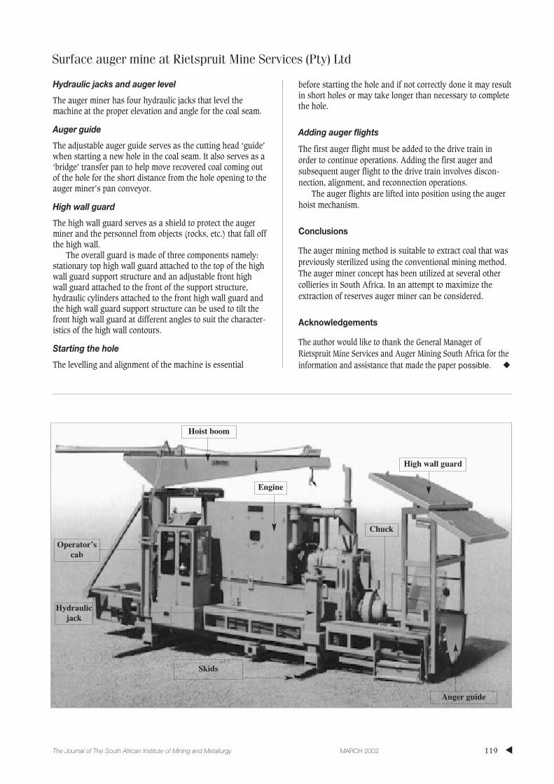
Hydraulic jacks and auger level
The auger miner has four hydraulic jacks that level themachine at the proper elevation and angle for the coal seam.
Auger guide
The adjustable auger guide serves as the cutting head ‘guide’when starting a new hole in the coal seam. It also serves as a‘bridge’ transfer pan to help move recovered coal coming outof the hole for the short distance from the hole opening to theauger miner’s pan conveyor.
High wall guard
The high wall guard serves as a shield to protect the augerminer and the personnel from objects (rocks, etc.) that fall offthe high wall.
The overall guard is made of three components namely:stationary top high wall guard attached to the top of the highwall guard support structure and an adjustable front highwall guard attached to the front of the support structure,hydraulic cylinders attached to the front high wall guard andthe high wall guard support structure can be used to tilt thefront high wall guard at different angles to suit the character-istics of the high wall contours.
Starting the hole
The levelling and alignment of the machine is essential
before starting the hole and if not correctly done it may resultin short holes or may take longer than necessary to completethe hole.
Adding auger flights
The first auger flight must be added to the drive train inorder to continue operations. Adding the first auger andsubsequent auger flight to the drive train involves discon-nection, alignment, and reconnection operations.
The auger flights are lifted into position using the augerhoist mechanism.
Conclusions
The auger mining method is suitable to extract coal that waspreviously sterilized using the conventional mining method.The auger miner concept has been utilized at several othercollieries in South Africa. In an attempt to maximize theextraction of reserves auger miner can be considered.
Acknowledgements
The author would like to thank the General Manager ofRietspruit Mine Services and Auger Mining South Africa for theinformation and assistance that made the paper possible. ◆
Hoist boom
High wall guard
Chuck
Engine
Operator’scab
Hydraulicjack
Auger guide
Skids

▲
120 MARCH 2002 The Journal of The South African Institute of Mining and Metallurgy