supporting information - pnas.org · with a larger young’s modulus than ecoflex 00-30. the...
TRANSCRIPT

Supporting InformationShepherd et al. 10.1073/pnas.1116564108SI Materials and MethodsSoft Robot Fabrication. Masters for the pneu-nets (PNs) were fab-ricated in acrylonitrile butadiene styrene (ABS) using a three-dimensional (3D) printer (Dimension 3D; Stratasys, Inc.) Wemolded PNs into a highly extensible, elastomeric material(Ecoflex 00-30; Smooth-On, Inc.) and then layered them ontoa relatively inextensible, compliant sheet [poly(dimethyl siloxane)(PDMS); Sylgard 184, Dow Corning] (Fig. 1). We then insertedfive soft, flexible tubes (1 mm i.d., silicone rubber) into a hublocated at the posterior section of the soft robot; this hub fedthe five separate PNs (the tubing was held in place by compres-sion from the surrounding, punctured Ecoflex silicone rubber).We also fabricated a robot capable of faster crawling locomotionusing an extensible elastomer (Ecoflex 00-50; Smooth-On, Inc.)with a larger Young’s Modulus than Ecoflex 00-30. The physicaldimensions of the robot, as well as the dimensions of the PNs areshown in Fig. S1. Both the Ecoflex elastomers, as well as the Syl-gard 184 were cured at 75 °C for 60 min prior to use. We glued thecured Ecoflex layer to the cured Sylgard 184 layer by using a thin,uncured layer of Sylgard 184 as glue; we then allowed the uncuredPDMS to permeate into the Ecoflex and Sylgard 184 layers for60 min and finished the bonding of the glue layer by baking therobot in an oven at 75 °C for 60 min. To increase productionthroughput, we typically fabricated four robots in parallel.
Manual Control for Obstacle Navigation.We connected the four legsof the robot to Manifold One (M1; manifold here means a groupof pressure regulators such as buttons and toggle switches) atpressure, P1, and the spine was connected to either M1 forundulation or Manifold Two (M2) at a lower pressure, P2 (4 psi),for crawling. M1 has button valves, which allowed the PNsto be pressurized when depressed, and vented to atmosphericwhen released (Fig. S2). M2 had a switch valve that kept thePNs pressurized until the valve was switched off.
Kinematic Analysis.We determined the speed of actuation of a leg(PN 5) of the tetrapod for different input pressures (Fig. S3). Wecaptured video at 200 frames per second (fps) using a high speedvideo camera (Phantom V7.1; Vision Research) and calculatedthe time it took for the leg to reach a curvature of 1 cm for pres-sures varying from 4.5 psi to 20.0 psi. We also tracked the motionof the robot during an undulation and crawling sequence. Weused MATLAB 2009a (The Mathworks, Inc.) Image Toolbox todetermine the center of mass of the robot (centroid) for eachframe of the videos shown in Movie S1 and Movie S2. We plottedthe X- and Y-position of the centroid vs. time for undulationand crawling gaits (Fig. S4). For the crawling gait, we inflatedthe robot’s spine after eight seconds and initiated crawling atthirteen seconds. For both gaits, after approximately 35 s, thetether begins to affect the weighting of the centroid and reducesthe positional accuracy of our image analysis.
SI TextCurvature (κ) of a PressurizedMembrane.Fig. S5A shows a schematicdrawing of an elastomer membrane incorporating embeddedpneumatic channels (represented by circles). The bottom layer ofthe membrane structure is assumed to be unstretchable, but to pos-sess negligible thickness so that the layer does not have significantbending modulus. Pneumatic channels are assumed to be circularfor the sake of analytical simplicity. Each of the pneumatic chan-nels is assumed to have infinite length (along the z axis in thefigure). In Fig. S5A, the pneumatic channels are not pressurized
(atmospheric pressure Patm inside the channels) and the mem-brane is at its resting, flat state (the radius of an undeformed chan-nel is Ratm, and length of the membrane ¼ 2Ratm × N; N is thenumber of channels). Fig. S5B shows the shape of the membranewhen the pneumatic channels are pressurized (P1 > Patm). Thechannels expand (Ratm → R1) to adopt the new pressure, leadingto a mismatch between the lengths of the membrane along the cen-ter of pneumatic channels (2R1 ×N) and along the unstretchedbottom layer (2Ratm × N). Eq. S1 describes the kinematic correla-tion between radius of curvature of the membrane (Rm ¼ 1∕κ;see Fig. S5C for parameters) and the expansion of the pneumaticcells (Ratm → R1):
Rm
Rm − R1
¼ R1
Ratm: [S1]
Eqs. S2–S5 relate the expansion of pneumatic cells(Ratm → R1) and the applied pressure (P1, Patm; Pa or kgm−1 s−2),based on the free-body diagram shown in Fig. S5D. To balance thepressure difference across the walls of pneumatic cells, the ten-sional force (T; per unit length along z axis; kg s−2) along the wallshould be (1):
2T ¼ 2R1ðP1 − PatmÞ: [S2]
The constitutive equation Eq. S3 describes the wall-tension T as afunction of the strain of the material (1):
T ¼ E · t · ε: [S3]
In Eq. S3, E ðkgm−1 s−2Þ, t ðmÞ, and ε are the elastic modulus,thickness, and strain [ε ¼ ðR1 − RatmÞ∕Ratm] of the channel wall,respectively. Stress-strain relationship for elastomers is highlynonlinear—both the elastic modulus of elastomer and the thick-ness of a channel wall changes as a pneumatic cell is stretched.We ignore these nonlinearities in this analysis as we are interestedonly in the order of magnitude relationship between the curva-ture of a membrane and the applied pressure. Combining Eqs. S2and S3, one can eliminate the term T and obtain a direct relationbetween the applied pressure and the strain of pneumatic cells:
ε ¼ RatmðP1 − PatmÞEt − RatmðP1 − PatmÞ
: [S4]
The ratio between radii of the inflated and the original pneumaticcells (χ ¼ R1∕Ratm ¼ 1þ ε) is then:
χ ¼ R1
Ratm¼ Et
Et − RatmðP1 − PatmÞ: [S5]
Combining Eqs. S1 and S5 leads to an explicit equation thatallows us to describe the curvature κ in terms of the expansionratioχ, and eventually the applied pressure (P1 − Patm):
κ ¼ 1
Ratm·χ − 1
χ2: [S6]
Fig. S6 shows the curvature of the membrane of typical para-meters (E ∼ 40 kPa, Ratm ∼ 1 mm, and t ∼ 1 mm) plotted tothe difference of pressures (P1 − Patm). The solid line representsthe curvature multiplied by the initial radius of pneumatic cells(Rm) and is nonmonotonic. This nonmonotonic behavior is be-
Shepherd et al. www.pnas.org/cgi/doi/10.1073/pnas.1116564108 1 of 7
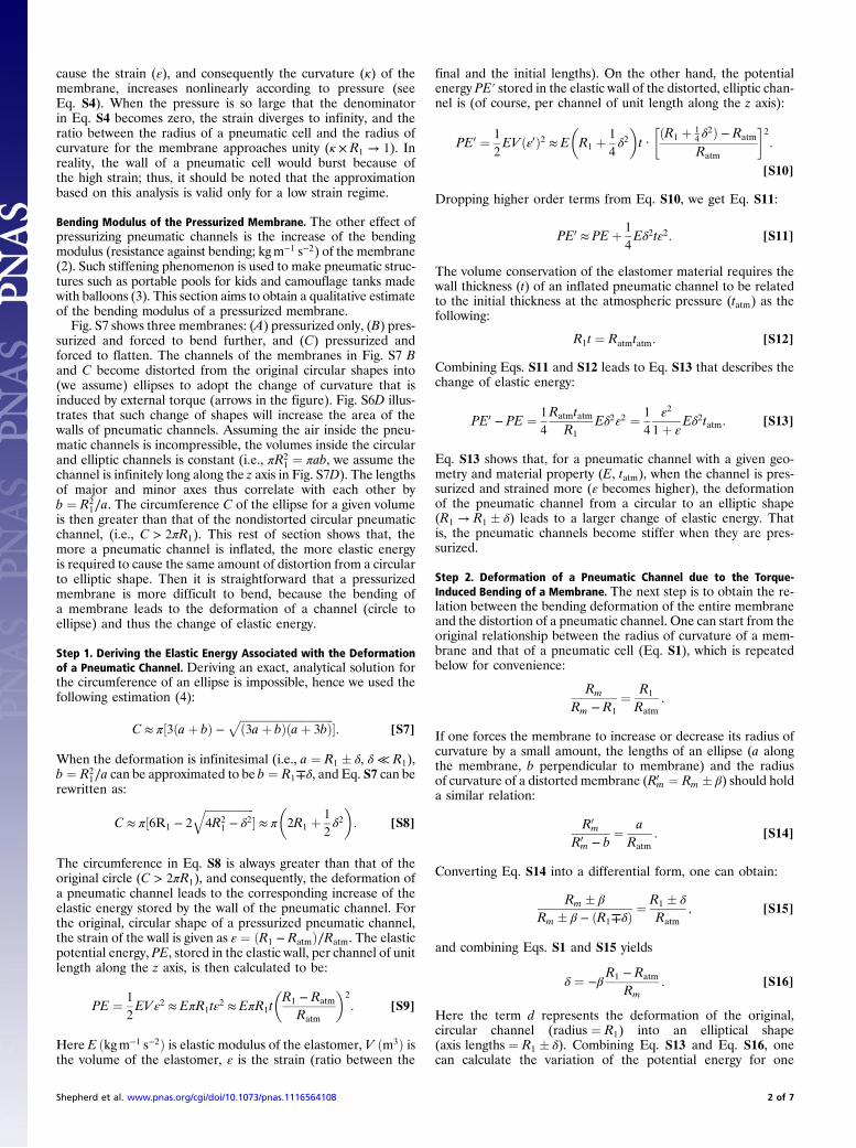
cause the strain (ε), and consequently the curvature (κ) of themembrane, increases nonlinearly according to pressure (seeEq. S4). When the pressure is so large that the denominatorin Eq. S4 becomes zero, the strain diverges to infinity, and theratio between the radius of a pneumatic cell and the radius ofcurvature for the membrane approaches unity (κ × R1 → 1). Inreality, the wall of a pneumatic cell would burst because ofthe high strain; thus, it should be noted that the approximationbased on this analysis is valid only for a low strain regime.
Bending Modulus of the Pressurized Membrane. The other effect ofpressurizing pneumatic channels is the increase of the bendingmodulus (resistance against bending; kgm−1 s−2) of the membrane(2). Such stiffening phenomenon is used to make pneumatic struc-tures such as portable pools for kids and camouflage tanks madewith balloons (3). This section aims to obtain a qualitative estimateof the bending modulus of a pressurized membrane.
Fig. S7 shows three membranes: (A) pressurized only, (B) pres-surized and forced to bend further, and (C) pressurized andforced to flatten. The channels of the membranes in Fig. S7 Band C become distorted from the original circular shapes into(we assume) ellipses to adopt the change of curvature that isinduced by external torque (arrows in the figure). Fig. S6D illus-trates that such change of shapes will increase the area of thewalls of pneumatic channels. Assuming the air inside the pneu-matic channels is incompressible, the volumes inside the circularand elliptic channels is constant (i.e., πR2
1 ¼ πab, we assume thechannel is infinitely long along the z axis in Fig. S7D). The lengthsof major and minor axes thus correlate with each other byb ¼ R2
1∕a. The circumference C of the ellipse for a given volumeis then greater than that of the nondistorted circular pneumaticchannel, (i.e., C > 2πR1). This rest of section shows that, themore a pneumatic channel is inflated, the more elastic energyis required to cause the same amount of distortion from a circularto elliptic shape. Then it is straightforward that a pressurizedmembrane is more difficult to bend, because the bending ofa membrane leads to the deformation of a channel (circle toellipse) and thus the change of elastic energy.
Step 1. Deriving the Elastic Energy Associated with the Deformationof a Pneumatic Channel. Deriving an exact, analytical solution forthe circumference of an ellipse is impossible, hence we used thefollowing estimation (4):
C ≈ π½3ðaþ bÞ −ffiffiffiffiffiffiffiffiffiffiffiffiffiffiffiffiffiffiffiffiffiffiffiffiffiffiffiffiffiffiffiffiffiffið3aþ bÞðaþ 3bÞ
p�: [S7]
When the deformation is infinitesimal (i.e., a ¼ R1 � δ, δ ≪ R1),b ¼ R2
1∕a can be approximated to be b ¼ R1∓δ, and Eq. S7 can berewritten as:
C ≈ π½6R1 − 2
ffiffiffiffiffiffiffiffiffiffiffiffiffiffiffiffiffiffi4R2
1 − δ2q
� ≈ π
�2R1 þ
1
2δ2�: [S8]
The circumference in Eq. S8 is always greater than that of theoriginal circle (C > 2πR1), and consequently, the deformation ofa pneumatic channel leads to the corresponding increase of theelastic energy stored by the wall of the pneumatic channel. Forthe original, circular shape of a pressurized pneumatic channel,the strain of the wall is given as ε ¼ ðR1 − RatmÞ∕Ratm. The elasticpotential energy, PE, stored in the elastic wall, per channel of unitlength along the z axis, is then calculated to be:
PE ¼ 1
2EVε2 ≈ EπR1tε2 ≈ EπR1t
�R1 − Ratm
Ratm
�2
: [S9]
Here E ðkgm−1 s−2Þ is elastic modulus of the elastomer, V ðm3Þ isthe volume of the elastomer, ε is the strain (ratio between the
final and the initial lengths). On the other hand, the potentialenergy PE′ stored in the elastic wall of the distorted, elliptic chan-nel is (of course, per channel of unit length along the z axis):
PE0 ¼ 1
2EV ðε0Þ2 ≈ E
�R1 þ
1
4δ2�t ·
�ðR1 þ 14δ2Þ − Ratm
Ratm
�2
:
[S10]
Dropping higher order terms from Eq. S10, we get Eq. S11:
PE0 ≈ PEþ 1
4Eδ2tε2: [S11]
The volume conservation of the elastomer material requires thewall thickness (t) of an inflated pneumatic channel to be relatedto the initial thickness at the atmospheric pressure (tatm) as thefollowing:
R1t ¼ Ratmtatm: [S12]
Combining Eqs. S11 and S12 leads to Eq. S13 that describes thechange of elastic energy:
PE0 − PE ¼ 1
4
RatmtatmR1
Eδ2ε2 ¼ 1
4
ε2
1þ εEδ2tatm: [S13]
Eq. S13 shows that, for a pneumatic channel with a given geo-metry and material property (E, tatm), when the channel is pres-surized and strained more (ε becomes higher), the deformationof the pneumatic channel from a circular to an elliptic shape(R1 → R1 � δ) leads to a larger change of elastic energy. Thatis, the pneumatic channels become stiffer when they are pres-surized.
Step 2. Deformation of a Pneumatic Channel due to the Torque-Induced Bending of a Membrane. The next step is to obtain the re-lation between the bending deformation of the entire membraneand the distortion of a pneumatic channel. One can start from theoriginal relationship between the radius of curvature of a mem-brane and that of a pneumatic cell (Eq. S1), which is repeatedbelow for convenience:
Rm
Rm − R1
¼ R1
Ratm:
If one forces the membrane to increase or decrease its radius ofcurvature by a small amount, the lengths of an ellipse (a alongthe membrane, b perpendicular to membrane) and the radiusof curvature of a distorted membrane (R0
m ¼ Rm � β) should holda similar relation:
R0m
R0m − b
¼ aRatm
: [S14]
Converting Eq. S14 into a differential form, one can obtain:
Rm � β
Rm � β − ðR1∓δÞ ¼R1 � δ
Ratm; [S15]
and combining Eqs. S1 and S15 yields
δ ¼ −βR1 − Ratm
Rm: [S16]
Here the term d represents the deformation of the original,circular channel (radius ¼ R1) into an elliptical shape(axis lengths ¼ R1 � δ). Combining Eq. S13 and Eq. S16, onecan calculate the variation of the potential energy for one
Shepherd et al. www.pnas.org/cgi/doi/10.1073/pnas.1116564108 2 of 7

pneumatic channel, per given change of radius of membranecurvature β:
PE0 − PE ¼ 1
4
RatmtatmR1
Eδ2ε2 ¼ 1
4Etatm
�Ratm
Rm
�2 ε4
1þ εβ2; [S17]
meaning the change of elastic energy (PE0 − PE) due to thetorque-induced bending of the membrane (Rm → Rm � β) ishighly dependent on the prestrain (ε) of the pneumatic channelsthat was caused by the pressure. In short, pressurized membranesbecome stiffer.
1. Timoshenko SP (1970) Theory of Elasticity (McGraw-Hill, New York).2. Tabata O, Konishi S, Cusin P, Ito Y, Kawai F, Hirai S, Kawamura S (2001)Micro fabricated
tunable bending stiffness devices. Sens Actuators A 89:119–123.3. Chi JY, Paulettie RMO (2005) An outline of the evolution of pneumatic structures. II
Simposio Latinoamericano de Tensoestructuras Caracas, Venezuela, May 4–5 2005.
Available at: http://www.lmc.ep.usp.br/people/pauletti/Publicacoes_arquivos/Chi-and-
Pauletti.Pdf.
4. Luchsinger RH, Pedretti M, Reinhard A (2004) Pressure induced stability: From pneu-
matic structures to Tensairity. J Bionic Eng 1:141–148.
Fig. S1. (A) Top view of the quadruped, with dimensions in millimeters. The length of the robot is 135.7 mm, the width 58.5 mm. (B) The side view of PN 3,showing the thickness of the Ecoflex layer (Layer 1) to be 5.3 mm, the pneu-net channel thickness to be 0.5 mm, the channel connecting the PNs to be 1.0 mmthick, and the Sylgard 184 (Layer 2) strain limiting layer to be 1.0 mm.
Fig. S2. (A) Computer control. Schematic diagram of a system of solenoid-valves controlled via computer. The computer is programmed to actuate the softrobot in undulation or crawling gait at a pressure of 7 psi. (B) Manual control. Schematic diagram of a system of spring-valves controlled via manual operation(depressing the spring-valve actuates the corresponding PN). The valve configuration for (Top) undulation gait requires a valve for each PN and uses a pressureof 7 psi. The (Bottom) crawl gait uses an individual valve for PNs 1, 2, 4, and 5. PN 3 is held at a constant pressure of 4 psi. The direction of the pressurizedair-flow is indicated by the arrow direction and the solenoid-valves are represented by a slanted line in a circle and the spring-valves are represented by azigzagged line in a circle.
Shepherd et al. www.pnas.org/cgi/doi/10.1073/pnas.1116564108 3 of 7

Fig. S3. Time to actuate (squares) and deactuate (circles) PN 5 to a 1-cm radius of curvature. Error bars are for n ¼ 7 replicates. Data obtained using high speedvideo (Phantom V7.1) at 200 fps.
Fig. S4. The x- and y-position of the center of mass of the robot vs. actuation time for (A) undulating and (B) crawling gait. Obtained using MATLAB R2009aimage analysis on Movie S1 and Movie S2.
Shepherd et al. www.pnas.org/cgi/doi/10.1073/pnas.1116564108 4 of 7

Fig. S5. (A) Schematic illustrating an elastomer membrane with N pneumatic channels. Circles represent pneumatic channels, possessing infinite length alongthe z axis. The pressure inside the pneumatic channels is atmospheric, and the membrane is at its resting state. (B) Same membrane at its pressurized state(P1 > Patm). Pneumatic channels now have larger radius R1 and the membrane spontaneously bends upward due to the mismatch between the lengths of thebottom layer (2Ratm × N) and along the pneumatic channels (2R1 × N). (C) A free-body diagram of an upper half of a pressurized pneumatic channel. (D)Parameters of a pressurized membrane.
Fig. S6. Curvature of a membrane plotted with respect to the pressure difference (P1 − Patm); the parameters for the membrane were E ¼ 40 kPa,Ratm ¼ 1 mm, and t ¼ 1 mm. Circles represent pneumatic channels, possessing infinite length along the z axis. The solid line represents the curvature multipliedby the initial radius of the pneumatic cells and the dashed line represents the curvature multiplied by the final radius of the pneumatic cells.
Shepherd et al. www.pnas.org/cgi/doi/10.1073/pnas.1116564108 5 of 7

Fig. S7. Schematics showing pressurizedmembranes, (A) without additional torque, (B) with a torque that further bends, or (C) flattens the membranes. Blackarrows indicate the direction of the applied torque. (D) Cross-sectional shapes of undistorted (Left) and distorted (Right) pneumatic channels.
Movie S1. Real-time video of soft robot undulation.
Movie S1 (WMV)
Shepherd et al. www.pnas.org/cgi/doi/10.1073/pnas.1116564108 6 of 7

Movie S2. Real-time video of soft robot crawling.
Movie S2 (WMV)
Movie S3. Real-time video of soft robot crawling using high modulus (Ecoflex 00-50) PNs.
Movie S3 (WMV)
Movie S4. Real-time video of the soft robot transitioning from crawling to undulating and back to crawling to navigate an obstacle: a glass plate elevated2 cm from the ground.
Movie S4 (WMV)
Shepherd et al. www.pnas.org/cgi/doi/10.1073/pnas.1116564108 7 of 7