support analysis of main tunnels in tabas mechanized
TRANSCRIPT
Journal of Mining and Environment (JME), Vol. 12, No. 3, 2021, 711-724
Corresponding author: [email protected] (M.H. Khosravi).
Shahrood University of Technology
Iranian Society of Mining
Engineering (IRSME)
Journal of Mining and Environment (JME)
journal homepage: www.jme.shahroodut.ac.ir
Support Analysis of Main Tunnels in Tabas Mechanized Parvadeh Mine at Intersection with Coal Seam Fazel Abbasi1, Mohammad Hossein Khosravi1*, Ahmad Jafari1, Ali Bashari2 and Behnam Alipenhani1
1. School of Mining Engineering, College of Engineering, University of Tehran, Tehran, Iran 2. Technical department at TPCCO, Tabas, Iran
Article Info Abstract
Received 5 March 2021 Received in Revised form 7 April 2021 Accepted 16 April 2021 Published online 16 April 2021 DOI:10.22044/jme.2021.10610.2014
The instability of the roof and walls of the tunnels excavated in coal mines has always attracted the attention of the miners and experts in this field. In this work, the instability of the main tunnels of the mechanized Parvadeh coal mine in Tabas, Iran, at the intersection with coal seam is studied. The main tunnels of this mine show significant horizontal displacements due to the complex ground conditions and great depth. The behavior of the rock mass surrounding the tunnel is investigated using various experimental methods, and according to the results obtained, the surrounding rock mass has squeezing conditions. In order to analyze the stability of the main tunnels, a series of 2D and 3D numerical modelings are performed using the FLAC2&3D finite difference software, and the results obtained are compared with the actual displacement values recorded in the walls of the main tunnels of the mine. The analysis results show that the tunnels under study are unstable with a steel frame support, and therefore, the use of different support systems for the stabilization is investigated. The results of modeling different types of support systems show that the use of shotcrete instead of galvanized sheet (as strut) does not have a significant effect on the reduced displacements. Also although the installation of steel sets is very effective in preventing the displacement of the walls, due to the swelling problems in the tunnel bottom and the placement of the conveyor and haulage rail, it cannot be used in practice. Finally, the use of truss bolt has yielded good results, and it can be proposed as a new support system in these tunnels. In addition, the modeling results show that in case the coal seam is higher than the tunnel foot, less displacement will occur in the tunnel walls compared to the other cases. In other words, changing the tunnel level in the future excavations can help reduce the displacements.
Keywords
Stability analysis Numerical modeling Support system Parvadeh coal mine in Tabas Truss bolt
1. Introduction
The first scientific definition of the squeezing and swelling rocks was provided by Terzaghi: the squeezing rocks slowly advance into the tunnel without significantly increasing the volume. In contrast, the advance of the swelling rocks into the tunnel is mainly associated with the increase in volume [1]. In order to determine the squeezing conditions, Jethwa et al. [2] have expressed the degree of squeezing, obtained by dividing the compressive strength of the rock mass by the in-situ stress. They presented a table that assessed the ground conditions in terms of the squeezing
degree obtained. Singh et al. [3] have used the relationship between the overburden height and the rock mass quality index (Q) in order to assess the tunneling ground conditions. Aydan [4] has introduced five classes for squeezing based on the values of elastic, plastic, softening, and failure strains and the amount of strain calculated by the closed-form solution methods. In order to estimate the squeezing conditions by the experimental method of Aydan, the radial displacements obtained by the Carranza-Torres and Fairhurst's method were used [4]. Goel et al. [5] have
Abbasi et al Journal of Mining & Environment, Vol. 12, No. 3, 2021
712
proposed the rock mass number to avoid uncertainty in determining the SRF score. This number is obtained from the relation of the quality index of rock by setting the value of one for the SRF parameter. Palmstrom [6] has used the rock mass index (RMi) parameter in order to evaluate the squeezing potential in the continuous environments. In massive rocks, the value of the RMi parameter is considered equal to 50% of the compressive strength of an intact rock, and in non-massive rocks, this value is calculated using Equation (1) [7].
0.2
RMi 0.2 ( )
0.37( ( ))
Dci l r a b
l r a
J J J V
D J J J
(1)
where ݈ܬ denotes the reliability of the joint and ܸܾ is the volume of the rock blocks (m3). ݎܬ and ܬa are determined according to the rock mass engineering classification of Q.
Hoek and Marinos have investigated the squeezing potential, according to Table 1, based on the convergence degree of the tunnel, which is calculated using the numerical methods[7].
Table 1. Classification of squeezing by Hoek and Marinos [7]
Tunnel convergence < 1 1–2.5 2.5–5 5–10 > 10 Squeezing class NA Low Medium High Very high
The experimental methods for predicting the
support pressure include the Terzaghi, Deere, Barton, and Unal methods. The Barton method provides an acceptable method for estimating the support pressure under the squeezing and non-squeezing ground conditions in smaller tunnels. Singh et al. [8] have suggested the correction factors for the tunnel depth, closure, and time after the support. They modified the Barton relations for the short-term support pressure, and proposed equations for determining the short-term support pressure in the tunnels under the squeezing conditions [8]. Using the Scandinavian tunnel experiences and the information from Singh et al. and Goel et al, Bhasin and Gristad have introduced a new correction factor for poor qualities in the squeezing conditions [9]. Goel and Jethwa have proposed a relation for estimating the support pressure using RMR. One of the advantages of this relation is that it can be utilized in both the squeezing and non-squeezing conditions without having an advanced knowledge about the ground conditions [5].
Wang et al.[10] have reviewed a suitable support system for several tunnel excavations on the squeezing rocks in the Qingling-Daba mountainous squeezing area. Their proposed a support system including the installation of foot reinforcement bolt (FRB) and the use of a rigid, less deformable main support system that was performed well. Chhushyabaga et al. [11] have studied the effect of the presence of a fault near the tunnel on the design of the support system. They used the geological strength index (GSI) method in order to describe the rock mass and numerical method to analyze the support system. The values of displacement, stress, and yielded
elements were studied to study the effect of the fault. In a critical review, Ghorbani et al. [12] have reviewed the main characteristics and support requirements of the squeezing ground conditions and characteristics of the support functions. They introduced different types of energy-absorbing rock bolts and other support elements applicable for ground support in the burst-prone and squeezing grounds. They also discussed the important differences in the choice and economics of ground support strategies in the high-stress ground conditions between the civil tunnels and the mining excavations. Hussein et al. [13] have considered the empirical and numerical methods used to classify the rock masses, and evaluated the status to design a support system. Zhao et al. [14] have installed an intelligent monitoring system in a constructing tunnel in order to investigate the squeezing behavior of the rock mass and its impact on the support system. In their study, the large-scale displacements and pressure on the support system were measured. They considered the implemented monitoring system to be suitable for monitoring in the conditions of high squeezing.
Parts of the main tunnels of the mechanized Parvadeh mine in Tabas are excavated in the coal seam with a thickness of about 2 m. Therefore, the difference in the strength properties between the coal seam and the surrounding layers made of siltstone causes the squeezing behavior. In this case, the rocks move into the tunnel and cause problems in the support. This causes problems in the support bases or walls due to the displacements that occur in the rocks around the tunnel as a result of the obvious difference in their strength. In this work, the ground behavior in the

Abbasi et al Journal of Mining & Environment, Vol. 12, No. 3, 2021
713
studied section of the main tunnels of the Parvadeh mine in Tabas was evaluated using the experimental methods, and the squeezing intensity was determined. Then using the numerical finite difference method of the FLAC2&3D software, the displacements of the existing support system were analyzed and the various types of support systems were examined. The results of the constructed models were validated by comparing the observations and measuring the displacement values in different parts of the tunnel. Finally, based on the observations obtained from the displacements of different parts of the tunnel and the support analysis with numerical modeling, a solution was provided to improve the support in the points of the tunnel that were related to the coal seam.
2. Empirical evaluation of surrounding rock behavior
According to the International Society for Rock Mechanics (ISRM), squeezing is the time-dependent cut of a rock that causes the surrounding rocks to move towards the tunnel. This phenomenon is associated with large deformations and time-dependent convergences during the tunnel excavation. The squeezing conditions in the selected section of the tunnel are evaluated using various methods as what follows.
2.1 Singh et al. criterion This method is based on the experiences of 39
case studies. According to the studies collected from the rock mass quality index (Q) and overburden (H), Singh have provided a boundary between the squeezing and non-squeezing rocks, as shown in Figure 1. Equation (2) shows this criterion [8].
13350H Q (2)
In Figure 1, the area above the line indicates the squeezing-prone conditions, while the area below the line indicates the points that do not have a squeezing potential. In the tunnel under study, the value of the rock mass quality index is 0.18 and the overburden height in the section under study is 400 m [15]. Therefore, as indicated in Figure 1, the rock surrounding this tunnel will have the squeezing conditions.
2.2 Jethwa et al. criterion Jethwa et al. [2] have defined the squeezing
intensity of rock mass (ܰܿ) as Equation (3) using the uniaxial compressive strength parameter:
0
cm cmcN
H P
(3)
where σcm is the uniaxial compressive strength of the rock mass, H is the depth of the tunnel from the ground level, P0 is the in-situ stress, and γ is the unit weight of the surrounding rock.
Based on the Nc parameter, they introduced a table in order to predict the squeezing value and the intensity. According to this table, if the Nc parameter obtained is less than 0.4, the tunnel will have a high squeezing behavior. With increase in the value of Nc, the squeezing intensity decreases so that in the values above 2, the behavior of the rock mass will fall within the non-squeezing range.
Based on the information obtained for the tunnel under study, where γ = 26.5 kN/m3, H = 400 m, and σcm = 2Mpa, it leads to Nc = 0.19. Therefore, the squeezing conditions are met in this work.
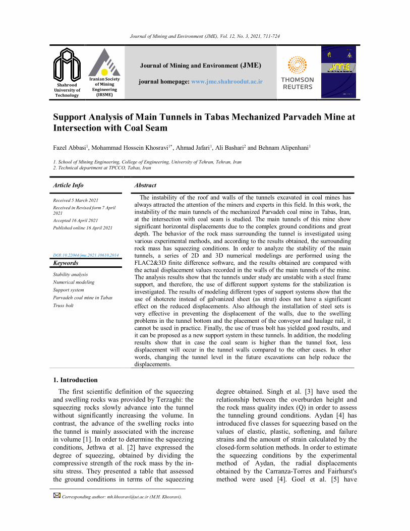
2.3 Hoek and Marinos criterion Hoek [7] has used the ratio of the uniaxial
compressive strength of rock mass (݉ܿߪ) to the in-situ stress (ܲ0) as an indicator in the tunnels, and Hoek and Marinos [7] have developed an efficiency diagram in order to evaluate the squeezing problem in the tunnels (Figure 2). According to this figure, with decrease in the ratio of the rock mass strength to the in-situ stress, and consequently, increasing the strain, the squeezing intensity of the tunnel increases. It can be observed that according to this criterion, as shown in Figure 2, the studied rock mass has squeezing conditions.
Figure 1. Squeezing criterion of Singh et al. [8]; the point indicating this study was added to the figure.
Abbasi et al Journal of Mining & Environment, Vol. 12, No. 3, 2021
714
3. 2D numerical modeling In order to construct the model, it was attempted
to use all the behavior conditions that may exist in the environment to bring the results closer to the reality. The dimensions of the model gradually changed with multiple iterations, and in each case, the stress contours in the vicinity of the external boundaries of the model were examined. Finally, the dimensions of the model were considered as 50 × 50 m. In the mentioned dimensions, the stress contours in the vicinity of the external boundaries of the model are very close to the in-situ stresses, and as a result, the selected boundary
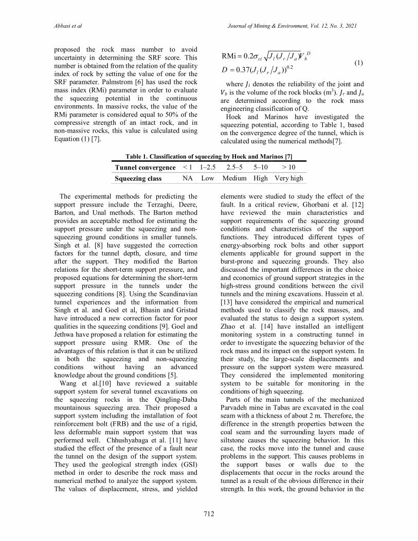
is sufficiently far from the tunnel impact area. In such cases, it is possible to ensure that the model boundaries do not affect the results. The constructed model was meshed by 250 units in the length direction and by 300 units in the height direction (Figure 3). The lateral boundaries were fixed with a roller abutment, and the lower boundary with an articulated abutment. In other words, the sides of the model are limited in the horizontal direction, and the lower part of the model is limited in the horizontal and vertical directions.
Figure 2. Classification of squeezing behavior
according to the Hoek criterion[7].
Figure 3. 2D model geometry.
It should be mentioned that the distance between the studied face and the stopes is more than 300 m, and the stopes are located at the top level of the tunnel. Therefore, exploitation operations have no effect on the modeling results and are not modeled.
In this work, the elastic–perfectly plastic Mohr-Coulomb model was used for siltstone and sandstone, which is common in the modeling of rock mechanics. The modeling was carried out by defining the discontinuity between the coal seam and siltstone and defining the creep behavior model for the coal seam. Note that the creep behavior was reported only for coal in this mine. According to the information available in the mine, the ratio of the horizontal to vertical stress in the numerical model is equal to 1.14. The rock mass parameters listed in Table 2, reported by Planning report of the Tabas mechanized Parvadeh coal mine technical department (1997) for the Parvadeh coal mine, are used in the model.
Table 2. Rock mass parameters used in the model [15].
Parameters Sandstone Siltstone Coal
Tensile strength (MPa) 6.3 2.5 0.002 Internal friction angle (Degree) 21.75 24.12 15 Dilation angle (Degree) 5 5 2 Shear modulus (GPa) 2.112 1.126 0.126 Bulk modulus (GPa) 3.52 1.970 0.210 Cohesion (MPa) 8.69 1.3 0.016
As the coal was very brittle, the sample
preparation was nearly impossible for this work. Therefore, some typical discontinuity characteristics and creep properties, reported by Xie and Zhao [16-18], were used in the model. According to them, coal has a discontinuity friction angle of 10 degrees and the normal and shear stiffness of 17 GPa and 1.8 GPa, respectively. Moreover, the creep properties of coal in Burgers model are E1 = 2.68 GPa, E2 = 12 GPa, η1 = 0.54 GPa.h, and η2 = 24 GPa.h.
Abbasi et al Journal of Mining & Environment, Vol. 12, No. 3, 2021
715
3.1 Excavation of tunnel space and application of support system
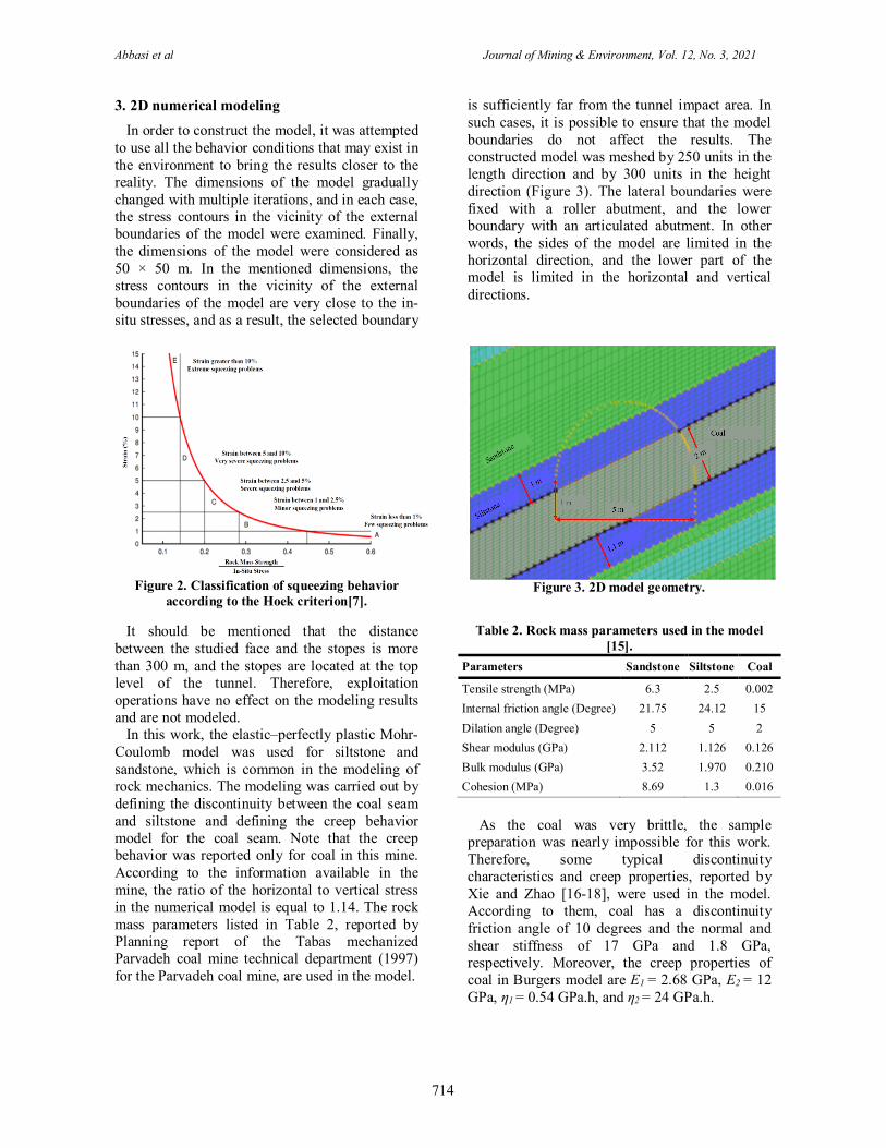
Since the support in the mine is installed immediately after excavating the tunnel, the support installation in the model is performed after the excavation using the Beam command. The data to be given in this command is the cross-sectional area of the frame, moment of inertia, density of steel, and modulus of elasticity of steel. The mine support system consists of a U-shaped steel frame with galvanized sheet metal lagging. The cross-section of the tunnel is horseshoe shaped with 5 m’ width and a height of 3.5 m. The common support system in the mine includes the U-shaped steel frames with galvanized sheets. The specifications of the steel frames used in this mine and also in the numerical modeling are shown in Table 3. Also similar to what is done in the mine, the distance between the frames is considered to be 1 m.
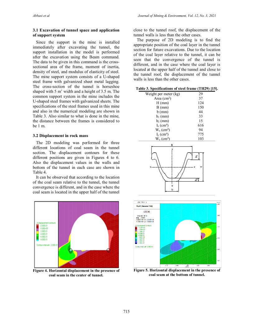
3.2 Displacement in rock mass The 2D modeling was performed for three
different locations of coal seam in the tunnel section. The displacement contours for these different positions are given in Figures 4 to 6. Also the displacement values in the walls and bottom of the tunnel in each case are shown in Table 4.
It can be observed that according to the location of the coal seam relative to the tunnel, the tunnel convergence is different, and in the case where the coal seam is located in the upper half of the tunnel
close to the tunnel roof, the displacement of the tunnel walls is less than the other cases.
The purpose of 2D modeling is to find the appropriate position of the coal layer in the tunnel section for future excavations. Due to the location of the coal layer relative to the tunnel, it can be seen that the convergence of the tunnel is different, and in the case where the coal layer is located at the upper half of the tunnel and close to the tunnel roof, the displacement of the tunnel walls is less than the other cases.
Table 3. Specifications of steel frame (TH29) [15]. Weight per meter (kg) 29
Area (cm2) 37 H (mm) 124 B (mm) 150 b (mm) 44 h1 (mm) 33 h2 (mm) 15 Ix (cm4) 616
Wx (cm4) 94 Iy (cm4) 775
Wy (cm4) 103
Figure 4. Horizontal displacement in the presence of
coal seam in the center of tunnel.
Figure 5. Horizontal displacement in the presence of
coal seam at the bottom of tunnel.

Abbasi et al Journal of Mining & Environment, Vol. 12, No. 3, 2021
716
Table 4. Displacements obtained in 2D model of tunnel with steel frame support (TH29). Location of coal seam
in tunnel section Max. horizontal displacement (cm) Max. vertical displacement (cm)
Right wall Left wall Bottom of tunnel Center 20 70 150 Bottom 125 0 250
Roof 2 7 8
Due to the fact that in most cases of the intersection of the main tunnel with the coal seam in the Parvadeh mine in Tabas, the location of the coal seam is similar to the situation shown in Figure 4, the location of the coal seam relative to the tunnel is modeled in 3D in the next section.
4. 3D modeling 4.1 Model geometry
In the geometry of the 3D model, the three-node mesh is used, which has a higher density around the tunnel. Figure 7 shows the model geometry including 2 m thick coal, 5 m thick siltstone seams above and below the coal seam, and sandstone that forms the rest of the environment. This model is developed with the length and height of 50 m and thickness of 20 m. According to what is done in the mine, was has been made to
apply the boundary conditions in the form of fixed displacement boundaries at the bottom of the model as fixed boundaries, and to apply the roller boundary conditions on the sides of the model. In the upper part of the block, according to the pressure from the existing overburden, the upper part boundary was applied as a stress boundary with a load equivalent to γZ, where γ is the rock mass density and Z is the overburden height. The depth of the studied tunnel in the numerical model is 400 m. The vertical stresses were considered as a product of the density and height of the overburden. Due to the density of the rock mass, which was about 2650 kg⁄m3, a vertical stress of 8.87 MPa was entered in the model. The horizontal shear stress in the Y and X directions is a product of the vertical stress entered in the model during the experimental analysis.
Figure 6. Horizontal displacement in the presence of
coal seam in the tunnel roof.
Figure 7. 3D model geometry.
4.2 Application of support system The support system of the main tunnels of the
mine is a horseshoe-shaped steel frame with a radius of 2.5 m and a height of 3.5 m, where the lateral distance of the frames is 1 m. The sandbags were used in order to fill the empty space behind the frames (20 cm). The distance between the steel frames was covered with 2 mm thick galvanized sheets. The properties of the
galvanized sheet used in the numerical model included the Young's modulus and Poisson's ratio equal to 210 GPa and 0.3, respectively. By applying the support, the results of the horizontal displacements after the equilibrium of the model are shown in Figure 8, and the comparison with the location of the initial frame is schematically shown in Figure 9.
Abbasi et al Journal of Mining & Environment, Vol. 12, No. 3, 2021
717
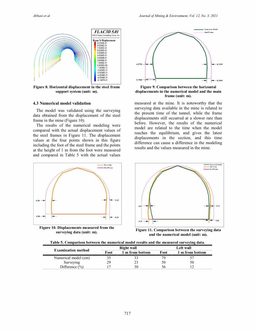
Figure 8. Horizontal displacement in the steel frame
support system (unit: m).
Figure 9. Comparison between the horizontal
displacements in the numerical model and the main frame (unit: m).
4.3 Numerical model validation
The model was validated using the surveying data obtained from the displacement of the steel frame in the mine (Figure 10).
The results of the numerical modeling were compared with the actual displacement values of the steel frames in Figure 11. The displacement values at the four points shown in this figure including the foot of the steel frame and the points at the height of 1 m from the foot were measured and compared in Table 5 with the actual values
measured at the mine. It is noteworthy that the surveying data available in the mine is related to the present time of the tunnel, while the frame displacements still occurred at a slower rate than before. However, the results of the numerical model are related to the time when the model reaches the equilibrium, and gives the latest displacements in the section, and this time difference can cause a difference in the modeling results and the values measured in the mine.
Figure 10. Displacements measured from the
surveying data (unit: m).
Figure 11. Comparison between the surveying data and the numerical model (unit: m).
Table 5. Comparison between the numerical model results and the measured surveying data.
Examination method Right wall Left wall Foot 1 m from bottom Foot 1 m from bottom
Numerical model (cm) 35 33 79 57 Surveying 29 23 50 50
Difference (%) 17 30 36 12

Abbasi et al Journal of Mining & Environment, Vol. 12, No. 3, 2021
718
4.4 Application of various types of support in numerical model
In order to apply the other types of support, a combination of steel frame with shotcrete, fiber-reinforced shotcrete, and rock bolt arrangement was used. The properties of the modeled rock bolt and shotcrete are given in Tables 6 and 7, respectively. The support combinations used for this tunnel in the model included changing the distance between the steel frames, replacing galvanized sheet with shotcrete, using fiber-reinforced shotcrete, and using rock bolt. Figure 12 shows the arrangement of 13 rock bolts with two different lengths of 2 m and 4 m in the model.
Table 6. Rock bolt specifications used in the model [15].
Modulus of elasticity (GPa) 210 Density (kg/m3) 7000 Cross-sectional area (m2) 0.00037994 Yield limit (kN) 152 Mortar cohesion (MPa) 0.8 Mortar stiffness (MN/m) 5640
Table 7. Shotcrete specifications used in the model [15].
Modulus of elasticity (GPa)
Poisson's ratio
Thickness (cm)
27 0.25 10
Figure 12. Arrangement of 13 rock bolts in the model.
4.5 Comparison between results of installing various types of support
The amount of displacement in the numerical models with various types of support system was measured for the four points specified in Figure 11 and summarized in Table 8. The results shown in this table are described below. The numbers shown in the titles of the following sections refer to the support number in Table 8.
a) Main support used in mine (No. 1)
The main support used in the main tunnels of the mine consists of a steel frame with the spacing
of 1 m and galvanized sheet. In this model, the displacements in the right and left feet are 35 and 79 cm, respectively, and in the walls at the height of 1 m from the tunnel bottom on the right and left are 32 and 57 cm, respectively.
b) Main support by reduced spacing between frames (No. 2)
In this support, the distance between the frames was reduced to 0.5 m. It can be observed that reducing the spacing between the frames reduces the displacements by 10% compared to the previous case.

Abbasi et al Journal of Mining & Environment, Vol. 12, No. 3, 2021
719
Table 8. Comparison between various support types applied in the numerical model.
Support No.
Support type Horizontal displacement (cm)
Steel frame galvanized sheet Shotcrete Rock bolt Right side Left side
Spacing (m) Invert Thickness
(m) Thickness
(m) Length
(m) Spacing
(m) Foot 1 m height from foot Foot 1 m height
from foot 1 1 0.002 35 32 79 57 2 0.5 0.002 30 28 70 46 3 1 0.1 32 30 75 56
3.1 1 0.1+mesh 30 28 61 45 4 0.5 0.1 31 32 69 45
4.1 0.5 0.1+mesh 29 22 65 41 5 1 0.002 2 1 30 29 56 43
5.1 1 0.002 2 1 30 29 54 41 6 1 0.002 4 1 28 27 47 38
6.1 1 0.002 4 1 29 26 46 36 7 1 0.002 2 0.5 30 28 43 33
7.1 1 0.002 2 0.5 30 27 41 33 8 1 0.002 4 0.5 29 26 40 30
8.1 1 0.002 4 0.5 28 25 39 30 9 1 0.1 2 1 30 25 57 42
9.1 1 0.1+mesh 2 1 27 24 52 35 10 1 0.002 2 8 2 4 11 1 0.1 4 10 5 7
11.1 1 0.1+mesh 3 8 4 5 12 1 0.002 2 1 2 7 2 5
c) Using shotcrete instead of galvanized sheet (No. 3 and 3.1)
In this type of support, instead of using the galvanized sheet, the shotcrete with the thickness of 10 cm is used, which has no significant effect on the results. However, in practice, the galvanized sheet is preferred due to the ease of installation. Although the use of mesh-reinforced shotcrete further reduces the displacement compared to shotcrete, the galvanized sheet is still preferred due to the insignificant impact.
d) Reduced spacing between frames with shotcrete (No. 4 and 4.1)
In this type of support, the displacements are reduced by 10% compared to the case where the frame with the distance of 1 m and shotcrete are used. Using the mesh-reinforced shotcrete, the displacement was not improved compared to the initial spacing of the frames.
e) Using rock bolt (No. 5 to 9.1)
This model uses 13 rock bolts, where the number of rock bolts in the walls and roof is 11, and there are two rock bolts in the feet. This system is not efficient enough to reduce the displacements. In addition, according to the results presented in Table 8, the installation of rock bolt under steel frame, increasing the length
of rock bolt and reducing the spacing were not so efficient in reducing the displacements.
f) Using steel inverts (No. 10 to 12)
The use of steel inverts in the original model significantly reduced the displacements. In the models consisting of steel inverts, the shotcrete and mesh-reinforced shotcrete are used instead of the galvanized sheet, and the results obtained are compared with the galvanized sheet. As with the previous cases, the use of galvanized sheet is recommended. Figure 13 shows the displacements in the steel frame with the presence of inverts.
Figure 13. Displacement in steel frame with inverts.
Comparing the results of installing various types of support, which are summarized in Table 8, it can be seen that the installation of the inverts with a steel frame has the greatest effect on the reduced
Abbasi et al Journal of Mining & Environment, Vol. 12, No. 3, 2021
720
displacement. The inverts prevent the convergence of the feet in the steel frame and considerably reduce the displacements.
Although the installation of steel inverts is very effective in preventing the displacement of the walls, due to the swelling problems in the tunnel bottom and the placement of the conveyor and haulage rail, it cannot be used in practice. Therefore, another approach should be adopted in order to solve the convergence problem of the main tunnels.
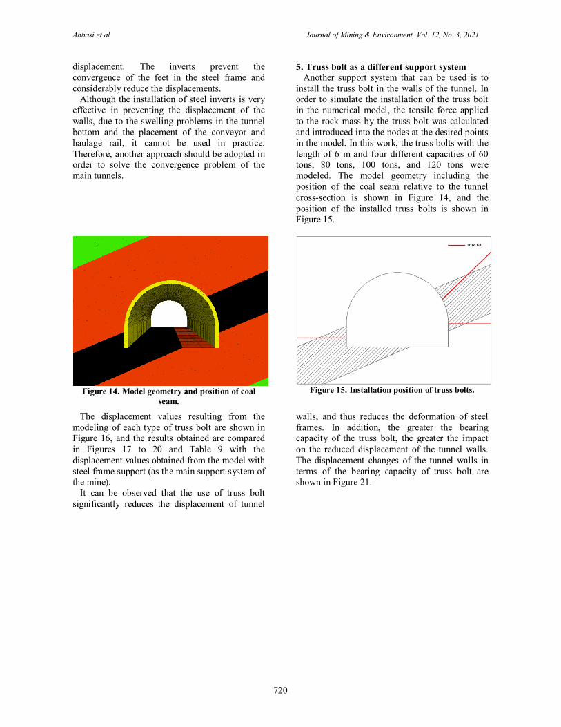
5. Truss bolt as a different support system Another support system that can be used is to
install the truss bolt in the walls of the tunnel. In order to simulate the installation of the truss bolt in the numerical model, the tensile force applied to the rock mass by the truss bolt was calculated and introduced into the nodes at the desired points in the model. In this work, the truss bolts with the length of 6 m and four different capacities of 60 tons, 80 tons, 100 tons, and 120 tons were modeled. The model geometry including the position of the coal seam relative to the tunnel cross-section is shown in Figure 14, and the position of the installed truss bolts is shown in Figure 15.
Figure 14. Model geometry and position of coal
seam.
Figure 15. Installation position of truss bolts.
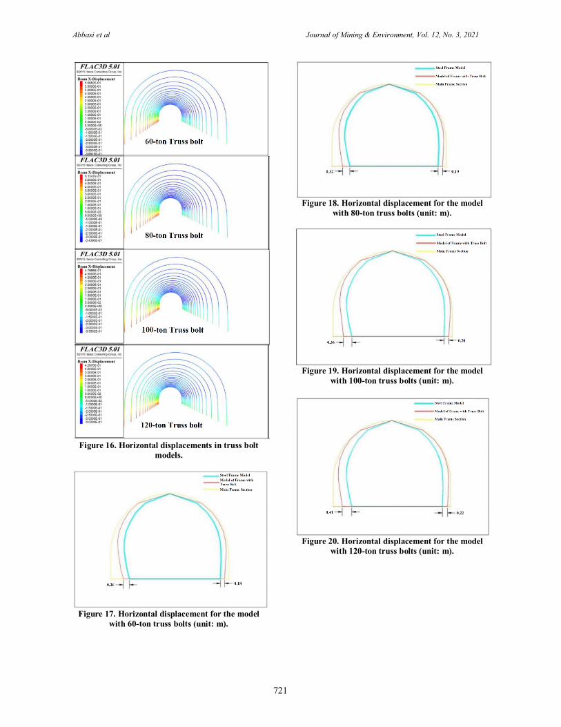
The displacement values resulting from the modeling of each type of truss bolt are shown in Figure 16, and the results obtained are compared in Figures 17 to 20 and Table 9 with the displacement values obtained from the model with steel frame support (as the main support system of the mine).
It can be observed that the use of truss bolt significantly reduces the displacement of tunnel
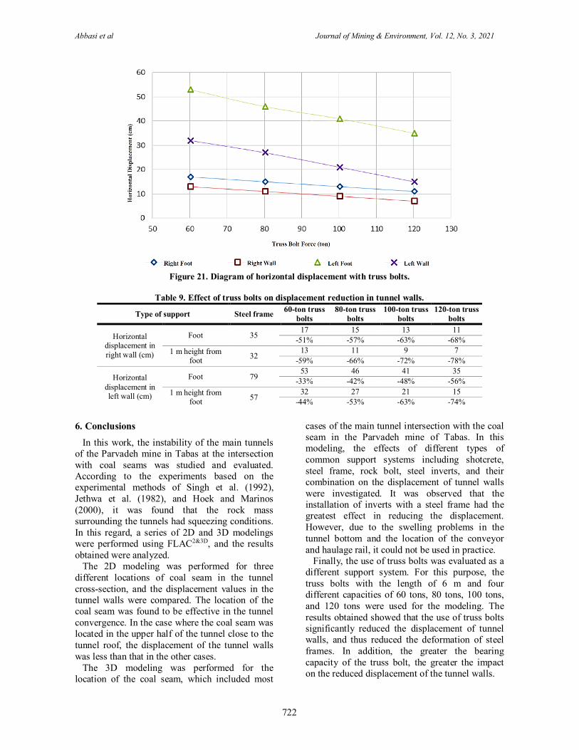
walls, and thus reduces the deformation of steel frames. In addition, the greater the bearing capacity of the truss bolt, the greater the impact on the reduced displacement of the tunnel walls. The displacement changes of the tunnel walls in terms of the bearing capacity of truss bolt are shown in Figure 21.
Abbasi et al Journal of Mining & Environment, Vol. 12, No. 3, 2021
721
Figure 16. Horizontal displacements in truss bolt
models.
Figure 17. Horizontal displacement for the model
with 60-ton truss bolts (unit: m).
Figure 18. Horizontal displacement for the model
with 80-ton truss bolts (unit: m).
Figure 19. Horizontal displacement for the model
with 100-ton truss bolts (unit: m).
Figure 20. Horizontal displacement for the model
with 120-ton truss bolts (unit: m).
Abbasi et al Journal of Mining & Environment, Vol. 12, No. 3, 2021
722
Figure 21. Diagram of horizontal displacement with truss bolts.
Table 9. Effect of truss bolts on displacement reduction in tunnel walls.
Type of support Steel frame 60-ton truss bolts
80-ton truss bolts
100-ton truss bolts
120-ton truss bolts
Horizontal displacement in right wall (cm)
Foot 35 17 15 13 11
-51% -57% -63% -68% 1 m height from
foot 32 13 11 9 7
-59% -66% -72% -78%
Horizontal displacement in left wall (cm)
Foot 79 53 46 41 35
-33% -42% -48% -56% 1 m height from
foot 57 32 27 21 15
-44% -53% -63% -74%
6. Conclusions
In this work, the instability of the main tunnels of the Parvadeh mine in Tabas at the intersection with coal seams was studied and evaluated. According to the experiments based on the experimental methods of Singh et al. (1992), Jethwa et al. (1982), and Hoek and Marinos (2000), it was found that the rock mass surrounding the tunnels had squeezing conditions. In this regard, a series of 2D and 3D modelings were performed using FLAC2&3D, and the results obtained were analyzed.
The 2D modeling was performed for three different locations of coal seam in the tunnel cross-section, and the displacement values in the tunnel walls were compared. The location of the coal seam was found to be effective in the tunnel convergence. In the case where the coal seam was located in the upper half of the tunnel close to the tunnel roof, the displacement of the tunnel walls was less than that in the other cases.
The 3D modeling was performed for the location of the coal seam, which included most
cases of the main tunnel intersection with the coal seam in the Parvadeh mine of Tabas. In this modeling, the effects of different types of common support systems including shotcrete, steel frame, rock bolt, steel inverts, and their combination on the displacement of tunnel walls were investigated. It was observed that the installation of inverts with a steel frame had the greatest effect in reducing the displacement. However, due to the swelling problems in the tunnel bottom and the location of the conveyor and haulage rail, it could not be used in practice.
Finally, the use of truss bolts was evaluated as a different support system. For this purpose, the truss bolts with the length of 6 m and four different capacities of 60 tons, 80 tons, 100 tons, and 120 tons were used for the modeling. The results obtained showed that the use of truss bolts significantly reduced the displacement of tunnel walls, and thus reduced the deformation of steel frames. In addition, the greater the bearing capacity of the truss bolt, the greater the impact on the reduced displacement of the tunnel walls.
Abbasi et al Journal of Mining & Environment, Vol. 12, No. 3, 2021
723
References [1] Steiner, W. (1996). Tunnelling in squeezing rocks: case histories. Rock Mechanics and Rock Engineering, 29 (4): 211-246.
[2] Jethwa, J.L., Dube, A.K., Singh, B., Singh, B. and Mithal, R.S. (1982). Evaluation of methods for tunnel support design in squeezing rock conditions. In International Association of Engineering geology. International congress. 4 (pp. 121-134).
[3] Singh, B. and Goel, R.K. (1999). Rock mass classification: a practical approach in civil engineering (Vol. 46). Elsevier.
[4] Aydan, Ö., Akagi, T. and Kawamoto, T. (1996). The squeezing potential of rock around tunnels: theory and prediction with examples taken from Japan. Rock mechanics and rock engineering. 29 (3): 125-143.
[5] Goel, R.K., Jethwa, J.L. and Paithankar, A.G. (1995). An empirical approach for predicting ground condition for runnelling and its practical benefits. In The 35th US Symposium on Rock Mechanics (USRMS). American Rock Mechanics Association.
[6] Palmström, A. (1996). Characterizing rock masses by the RMi for use in practical rock engineering: Part 1: The development of the Rock Mass index (RMi). Tunnelling and underground space technology. 11 (2): 175-188.
[7] Hoek, E. and Marinos, P. (2000). Predicting tunnel squeezing problems in weak heterogeneous rock masses. Tunnels and tunnelling international. 32 (11): 45-51.
[8] Singh, B., Goel, R.K., Jethwa, J.L. and Dube, A.K. (1997). Support pressure assessment in arched underground openings through poor rock masses. Engineering Geology. 48 (1-2): 59-81.
[9] Bhasin, R. and Grimstad, E. (1996). The use of stress-strength relationships in the assessment of tunnel stability. Tunnelling and Underground Space Technology. 11 (1): 93-98.
[10] Wang, X., Lai, J., Garnes, R.S. and Luo, Y. (2019). Support system for tunnelling in squeezing
ground of Qingling-Daba mountainous area: a case study from soft rock tunnels. Advances in Civil Engineering, 2019.
[11] Chhushyabaga, B., Karki, S. and Khadka, S.S. (2020). Tunnel support design in fault zone in hydropower project in the Nepal Himalaya: a case study. In Journal of Physics: Conference Series (Vol. 1608, No. 1, p. 012009). IOP Publishing.
[12] Ghorbani, M., Shahriar, K., Sharifzadeh, M. and Masoudi, R. (2020). A critical review on the developments of rock support systems in high stress ground conditions. International Journal of Mining Science and Technology.
[13] Hussian, S., Mohammad, N., Ur Rehman, Z., Khan, N.M., Shahzada, K., Ali, S. and Sherin, S. (2020). Review of the geological strength index (GSI) as an empirical classification and rock mass property estimation tool: origination, modifications, applications, and limitations. Advances in Civil Engineering.
[14] Zhao, Y.M., Han, Y., Kou, Y.Y., Li, L. and Du, J.H.; Three-Dimensional, Real-Time, and Intelligent Data Acquisition of Large Deformation in Deep Tunnels. Advances in Civil Engineering, 2021. [15] Planning report of the Tabas mechanized Parvadeh coal mine technical department.
[16] Xie, Y.S. and Zhao, Y.S. (2009). Numerical simulation of the top coal caving process using the discrete element method. International Journal of Rock Mechanics and Mining Sciences, 46 (6): 983-991.
[17] Kang, J., Zhou, F., Liu, C. and Liu, Y. (2015). A fractional non-linear creep model for coal considering damage effect and experimental validation. International Journal of Non-Linear Mechanics, 76: 20-28.
[18] Chia, K.S., Liu, X., Liew, J.Y. and Zhang, M. H. (2014). Experimental study on creep and shrinkage of high-performance ultra-lightweight cement composite of 60 MPa. Structural Engineering and Mechanics, 50 (5): 635-652.
1400 وم، سالس، دوره دوازدهم، شماره زیستپژوهشی معدن و محیط -نشریه علمی و همکاران عباسی
زغالسنگ پروده طبس در محل تقاطع با لایه مکانیزه هاي اصلی معدنتحلیل نگهداري تونل
1و بهنام علی پنهانی 2، علی بشري1، احمد جعفري*1، محمد حسین خسروي1فاضل عباسی
ایران، تهران، دانشگاه تهرانهاي فنی پردیس دانشکده، دانشکده مهندسی معدن - 1 ، طبس، ایراندفتر فنی و طراحی شرکت زغالسنگ پروده طبس - 2
16/04/2021، پذیرش 05/03/2021ارسال
.ac.ir.khosravi@utmh * نویسنده مسئول مکاتبات:
چکیده:
زغالسنگ همیشه یکــی از موضــوعات مــورد توجــه معــدنکاران و متخصصــان ایــن رشــته بــوده هاي حفر شده در معادن هاي تونلناپایداري سقف و دیواره موضوعهــاي زغالســنگ مــورد مطالعــه قــرار گرفتــه اســت. تونــلهاي اصلی معدن مکانیزه زغالسنگ پرورده طبس در محل تقــاطع بــا لایــهاست. در این تحقیق ناپایداري تونل
گیــر تونــل بــا اســتفاده از ســنگ دروندهنــد. رفتــار تودههاي افقی قابل توجهی را از خود نشان مــیق زیاد، جابجاییاصلی این معدن، بدلیل شرایط پیچیده زمین و عمهــاي شــوندگی اســت. بــه منظــور تحلیــل پایــداري تونــلگیر داراي شرایط مچالــهسنگ درونهاي تجربی مختلف مورد بررسی قرار گرفته و مشخص شد که تودهروش
انجام شده و نتایج آن با مقادیر واقعــی جابجــایی ثبــت شــده FLAC2&3Dافزار تفاضل محدود بعدي با استفاده از نرمي عددي دوبعدي و سهاصلی، یکسري مدلسازیــدار بــوده و هــاي مــورد مطالعــه بــا نگهــداري قــاب فــولادي ناپااصلی معدن مقایسه شد. نتایج به دست آمده از تحلیل ها نشان داد کــه تونــل هايهاي تونلدر دیواره
هــاي نگهــداري نشــان داد کــه هاي نگهداري مختلف مورد بررسی قرار گرفت. نتایج مدلسازي انــواع مختلــف سیســتمبنابراین به منظور پایدارسازي، استفاده از سیستمبنــد فــولادي در نــدارد. همچنــین، اگرچــه نصــب کــفهــا اي بــر روي کــاهش جابجــاییجاي ورق گالوانیزه (به عنوان لارده) تأثیر قابل ملاحظــهاستفاده از شاتکریت بهوجود مشکلات آماس در کف تونل و قرار گیري نوارنقالــه و ریــل بــاربري، اســتفاده از آن عمــلا امکــان دلیلبهها بسیار تأثیر گذار است، اماّ دیواره جلوگیري از جابجایی
هــا پیشــنهاد شــده اســت. عــلاوه بــر آن، ا نشان داده و به عنوان یک سیستم نگهداري جدید در این تونلپذیر نخواهد بود. نهایتا، استفاده از تراس بولت نتایج مطلوبی رهــاي تونــل اتفــاق کمتــري در مقایســه بــا حــالات دیگــر، در دیــواره تونل باشد مقدار جابجایی زغالسنگ بالاتر از پاشنه نتایج مدلسازي نشان داد که در حالتی که لایه
.ها کمک کندتواند به کاهش جابجاییعبارت دیگر تغییر تراز تونل در حفریات آتی میخواهد افتاد. به
.تحلیل پایداري، مدلسازي عددي، سیستم نگهداري، معدن زغالسنگ پروده طبس، تراس بولت کلمات کلیدي: