supply of carbon steel bare / coated line pipes for...
TRANSCRIPT

SUPPLY OF CARBON STEEL BARE /COATED LINE PIPES FOR NATURAL GASPIPELINES IN KG BASIN Project No. P.011097Document No. P.011097 D 11031 001E - Tender No. 8000014992
GAIL( India) LTD.NOIDA | INDIA
RESTRICTED
29 April 2019
TENDERTECHNICAL TENDER VOL II of II
S.No. Document / Drawing No. Rev. No. Pages Page No.
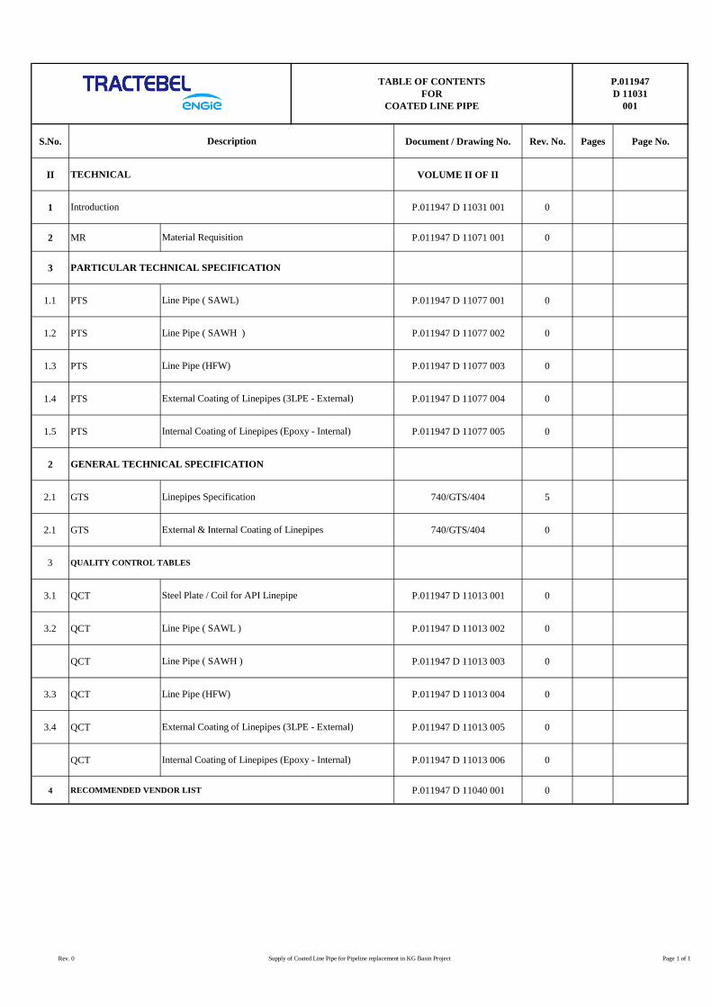
II VOLUME II OF II
1 P.011947 D 11031 001 0
2 MR P.011947 D 11071 001 0
3
1.1 PTS P.011947 D 11077 001 0
1.2 PTS P.011947 D 11077 002 0
1.3 PTS P.011947 D 11077 003 0
1.4 PTS P.011947 D 11077 004 0
1.5 PTS P.011947 D 11077 005 0
2
2.1 GTS 740/GTS/404 5
2.1 GTS 740/GTS/404 0
3
3.1 QCT P.011947 D 11013 001 0
3.2 QCT P.011947 D 11013 002 0
QCT P.011947 D 11013 003 0
3.3 QCT P.011947 D 11013 004 0
3.4 QCT P.011947 D 11013 005 0
QCT P.011947 D 11013 006 0
4 P.011947 D 11040 001 0RECOMMENDED VENDOR LIST
External Coating of Linepipes (3LPE - External)
Line Pipe ( SAWH )
QUALITY CONTROL TABLES
Steel Plate / Coil for API Linepipe
Line Pipe ( SAWL )
Line Pipe (HFW)
Line Pipe ( SAWH )
External Coating of Linepipes (3LPE - External)
Linepipes Specification
TABLE OF CONTENTSFOR
COATED LINE PIPE
Internal Coating of Linepipes (Epoxy - Internal)
External & Internal Coating of Linepipes
P.011947D 11031
001
Description
GENERAL TECHNICAL SPECIFICATION
Internal Coating of Linepipes (Epoxy - Internal)
PARTICULAR TECHNICAL SPECIFICATION
Line Pipe ( SAWL)
Line Pipe (HFW)
TECHNICAL
Material Requisition
Introduction
Rev. 0 Supply of Coated Line Pipe for Pipeline replacement in KG Basin Project Page 1 of 1

INTRODUCTION P.011947
D 11031
001
VENDOR LOGO
IRCA LOGO
PIPELINE REPLACEMENT IN KG BASIN PROJECT
TRACTEBEL ENGINEERING PVT. LTD.
INTRODUCTION
0 29.04.2019 Issued for Procurement Rajveer Panwar Nirjhar Chakrabarti SK Hussain
Rev. Date Description Prepared By Checked By Approved By

INTRODUCTION P.011947
D 11031
001
Rev. 0 Supply of Coated line Pipe for Pipeline replacement in KG Basin Project Page I of I
TABLE OF CONTENTS
1. INTRODUCTION ...................................................................................................................... 1
2. TECHNICAL SPECIFICATIONS ................................................................................................ 1
INTRODUCTION P.011947
D 11031
001
Rev. 0 Supply of Coated Linepipes for Pipeline Replacement in KG Basin Project Page 1 of 1
1. INTRODUCTION
GAIL India Limited (GAIL) is operating a network of Natural gas pipelines in the KG Basin area of Andhra
Pradesh, with total length spanning approx. 880 kms, for supplying gas to various customers in the region.
GAIL receiving gas from suppliers like ONGC, and transports it to various industrial customers / load centres,
through its existing Pipeline network.
GAIL is taking up replacement of pipeline / pipeline sections / station piping in KG Basin network &
intends to replace the Pipeline sections / terminals .
TRACTEBEL ENGINEERING pvt. Ltd. is now inviting tenders for procurement of “Coated Line Pipe” for
18 Inch sizes for this project.
The present document covers the technical specifications for the enquiry.
2. TECHNICAL SPECIFICATIONS
The technical specifications for this present enquiry are as listed in Material Requisition (Ref. No. P.011947 D
11071 001).
MATERIAL REQUISITION
P.011947
D 11071
001
VENDOR LOGO
IRCA LOGO
PIPELINE REPLACEMENT IN KG BASIN PROJECT
TRACTEBEL ENGINEERING PVT. LTD.
MATERIAL REQUISITION FOR COATED LINEPIPES
DOC. NO. P.011947 D 11071 001
0 29.04.2019 Issued for Procurement Rajveer Panwar Nirjhar Chakrabarti SK Hussain
Rev. Date Description Prepared by Checked by Approved by
MATERIAL REQUISITION
P.011947
D 11071
001
Rev. 0 Supply of Coated Line Pipe for Pipeline replacement in KG Basin Project Page 1 of 6
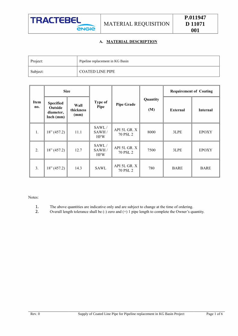
A. MATERIAL DESCRIPTION
Notes:
1. The above quantities are indicative only and are subject to change at the time of ordering.
2. Overall length tolerance shall be (-) zero and (+) 1 pipe length to complete the Owner’s quantity.
Project: Pipeline replacement in KG Basin
Subject: COATED LINE PIPE
Item
no.
Size
Type of
Pipe Pipe Grade
Quantity
(M)
Requirement of Coating
Specified
Outside
diameter,
Inch (mm)
Wall
thickness
(mm)
External Internal
1. 18” (457.2) 11.1
SAWL /
SAWH /
HFW
API 5L GR. X
70 PSL 2 8000 3LPE EPOXY
2. 18” (457.2) 12.7
SAWL /
SAWH /
HFW
API 5L GR. X
70 PSL 2 7500 3LPE EPOXY
3. 18” (457.2) 14.3 SAWL API 5L GR. X
70 PSL 2 780 BARE BARE
MATERIAL REQUISITION
P.011947
D 11071
001
Rev. 0 Supply of Coated Line Pipe for Pipeline replacement in KG Basin Project Page 2 of 6
B. REMARKS / COMMENTS
1. GENERAL NOTES
Vendor’s compliance
Vendor must include the following statement in his bid:
We certify that our bid is fully complying with your enquiry dated……………, and referenced……………….
Compliance with this material requisition in any instance shall not relieve the Vendor of his responsibility
to meet the specified performance.
2. COMPLIANCE WITH SPECIFICATION
The Vendor shall be completely responsible for the design, materials, fabrication, testing, inspection, and
preparation for shipment, transport of the above equipment or part thereof as relevant to his offer strictly in
accordance with the Material Requisition and all attachments thereto.
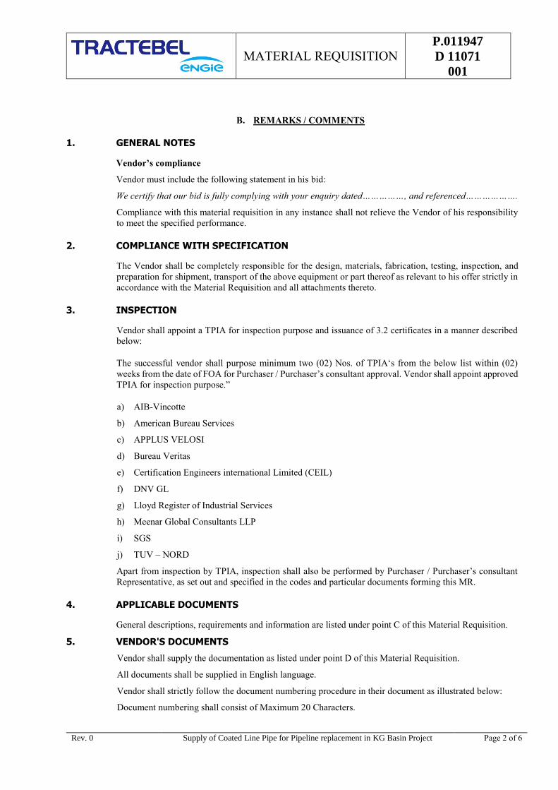
3. INSPECTION
Vendor shall appoint a TPIA for inspection purpose and issuance of 3.2 certificates in a manner described
below:
The successful vendor shall purpose minimum two (02) Nos. of TPIA‘s from the below list within (02)
weeks from the date of FOA for Purchaser / Purchaser’s consultant approval. Vendor shall appoint approved
TPIA for inspection purpose.”
a) AIB-Vincotte
b) American Bureau Services
c) APPLUS VELOSI
d) Bureau Veritas
e) Certification Engineers international Limited (CEIL)
f) DNV GL
g) Lloyd Register of Industrial Services
h) Meenar Global Consultants LLP
i) SGS
j) TUV – NORD
Apart from inspection by TPIA, inspection shall also be performed by Purchaser / Purchaser’s consultant
Representative, as set out and specified in the codes and particular documents forming this MR.
4. APPLICABLE DOCUMENTS
General descriptions, requirements and information are listed under point C of this Material Requisition.
5. VENDOR'S DOCUMENTS
Vendor shall supply the documentation as listed under point D of this Material Requisition.
All documents shall be supplied in English language.
Vendor shall strictly follow the document numbering procedure in their document as illustrated below:
Document numbering shall consist of Maximum 20 Characters.
MATERIAL REQUISITION
P.011947
D 11071
001
Rev. 0 Supply of Coated Line Pipe for Pipeline replacement in KG Basin Project Page 3 of 6
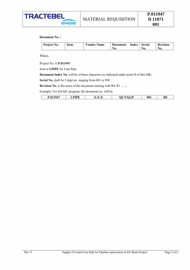
Document No. :
Project No. Item Vendor Name Document Index
No.
Serial
No.
Revision
No.
Where,
Project No. is P.011947
Item is LPIPE for Line Pipe
Document Index No. will be of three characters as indicated under point D of this MR;
Serial No. shall be 3 digit no. ranging from 001 to 999
Revision No. is Revision of the document starting with R0, R1 …..;
Example: For QA/QC program, the document no. will be
P.011947 LPIPE X-X-X QCT/QAP 001 R0

MATERIAL REQUISITION
P.011947
D 11071
001
Rev. 0 Supply of Coated Line Pipe for Pipeline replacement in KG Basin Project Page 4 of 6
C. LIST OF ATTACHMENTS
The table here below lists the documents which are integral
part of this Material Requisition. The applicable revision
index of each document is mentioned in the column below the
current Material Requisition revision index.
Material Requisition revision
When the Material Requisition revision index is "A" or "0", all
listed documents are attached. For other Material Requisition
revision index, only modified or new documents are attached.
0
Documents Revision of documents
PTS – Line Pipe (SAWL)
(Doc. No. P.011947 D 11077 001) 0
PTS – Line Pipe (SAWH)
(Doc. No. P.011947 D 11077 002) 0
PTS – Line Pipe (HFW)
(Doc. No. P.011947 D 11077 003) 0
PTS – 3LPE External coating
(Doc. No. P.011947 D 11077 004) 0
PTS – 3LPE Internal coating
(Doc. No. P.011947 D 11077 005) 0
GTS – Line Pipe
(Doc. No. 740/GTS/404 5
GTS – 3LPE External coating for Line Pipes
(Doc. No. 740/GTS/404 0
QCT for Steel plate/ Coil
(P.011947 D 11013 001) 0
QCT for Line Pipe (SAWL)
(P.011947 D 11013 002) 0
QCT for Line Pipe (SAWH)
(P.011947 D 11013 003) 0
QCT for Line Pipe (HFW)
(P.011947 D 11013 004) 0
QCT for 3LPE External coating
(P.011947 D 11013 005) 0
QCT for Internal coating
(P.011947 D 11013 006) 0
Recommended Vendor List
(P.011947 D 11040 001)

MATERIAL REQUISITION
P.011947
D 11071
001
Rev. 0 Supply of Coated Line Pipe for Pipeline replacement in KG Basin Project Page 5 of 6
D. DOCUMENTS & DATA REQUIREMENTS
The table hereunder specifies the quantities and the nature of the documents to be submitted by the MANUFACTURER
to the ENGINEER.
The documents required at the inquiry stage and to be included in the bid are listed under column A.
The documents required after award of the AGREEMENT and subject to the written approval of the ENGINEER are
listed under column B.
The final and certified documents are listed under column C.
Any document, even when preliminary, shall be binding and therefore duly identified and signed by the
MANUFACTURER. It shall bear the ENGINEER's Project reference, the Material Requisition number and the
identification number.
THE DOCUMENTS ARE FULLY PART OF THE SUPPLY WHICH SHALL BE COMPLETE ONLY IF AND WHEN
THE DOCUMENTS COMPLYING FULLY WITH THE MATERIAL REQUISITION REQUIREMENTS ARE
RECEIVED BY THE ENGINEER.
Item Documents and Data
A B C
Number
of copies
Number
of copies Required
date
Number
of copies Required
date
1. Drawing/data submittal list and
schedule
2 2 1 week +
monthly
2 2 weeks after
approval
2. Production, test and delivery schedule
(per item)
2 2 1 week +
monthly
2 2 weeks
3. Progress report - - 2 Daily +
weekly +
monthly
- - - -
4. Catalogues / References 2 - - - - - - - -
5. Description of application and quality
with technical data of 3LPE for
external coating
2 2 3 weeks 2 2 weeks after
approval +
with final
techn. file
6. Code compliance certificate(Quality
manual, ISO certificate, API License)
2 2 3 weeks 2 2 weeks after
approval
7. QA/QC program
( First Day Production + Regular
production separately )
2 2 2 weeks 2 2 weeks after
approval
8. Inspection and test procedures 2 2 3 weeks 2 2 weeks after
approval +
with final
techn. file
9. A description with calculation for
handling, storage, transportation
procedure during total manufacturing
cycle and long storage procedure
2 4 weeks - - - -
10. Duly filled & signed Technical
Questionnaire & documents as per
Appendix 1 of PTS.
2 - - - - - - - -
MATERIAL REQUISITION
P.011947
D 11071
001
Rev. 0 Supply of Coated Line Pipe for Pipeline replacement in KG Basin Project Page 6 of 6
Item Documents and Data
A B C
Number
of copies
Number
of copies Required
date
Number
of copies Required
date
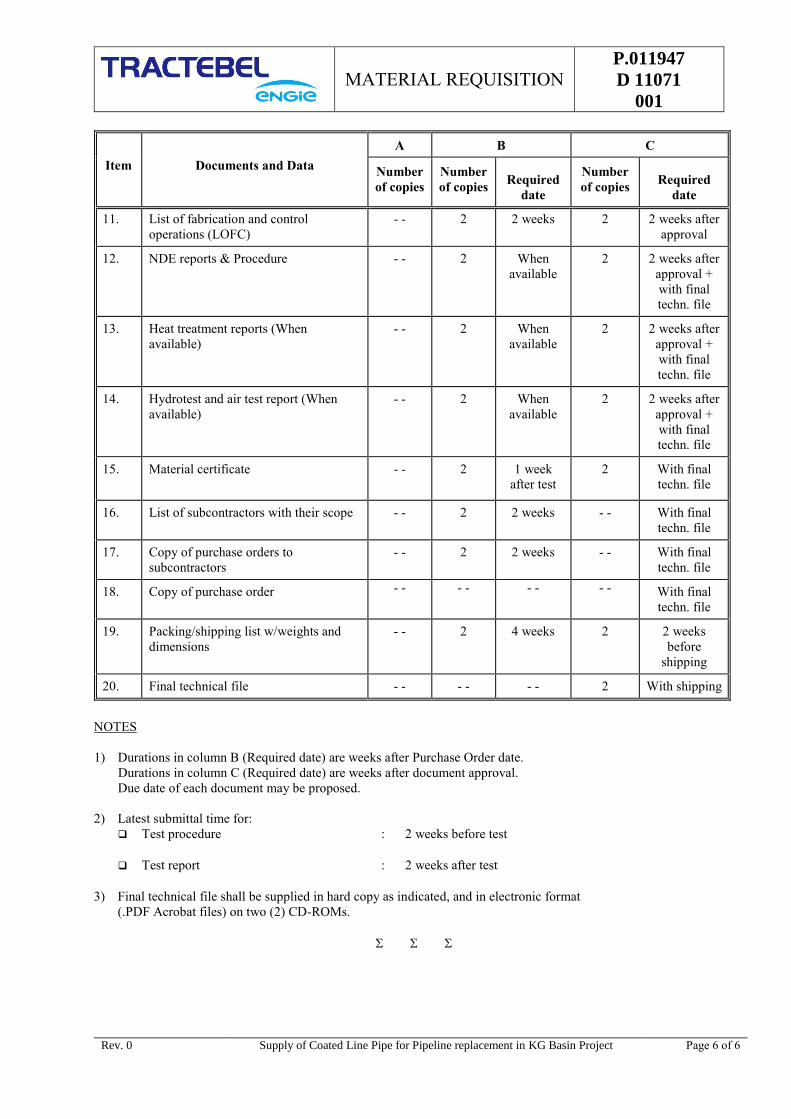
11. List of fabrication and control
operations (LOFC)
- - 2 2 weeks 2 2 weeks after
approval
12. NDE reports & Procedure - - 2 When
available
2 2 weeks after
approval +
with final
techn. file
13. Heat treatment reports (When
available)
- - 2 When
available
2 2 weeks after
approval +
with final
techn. file
14. Hydrotest and air test report (When
available)
- - 2 When
available
2 2 weeks after
approval +
with final
techn. file
15. Material certificate
- - 2 1 week
after test
2 With final
techn. file
16. List of subcontractors with their scope - - 2 2 weeks - - With final
techn. file
17. Copy of purchase orders to
subcontractors
- - 2 2 weeks - - With final
techn. file
18. Copy of purchase order - - - - - - - - With final
techn. file
19. Packing/shipping list w/weights and
dimensions
- - 2 4 weeks 2 2 weeks
before
shipping
20. Final technical file - - - - - - 2 With shipping
NOTES
1) Durations in column B (Required date) are weeks after Purchase Order date.
Durations in column C (Required date) are weeks after document approval.
Due date of each document may be proposed.
2) Latest submittal time for:
Test procedure : 2 weeks before test
Test report : 2 weeks after test
3) Final technical file shall be supplied in hard copy as indicated, and in electronic format
(.PDF Acrobat files) on two (2) CD-ROMs.
PTS - LINE PIPE (SAWL)
P.011947
D 11077
001
VENDOR LOGO
IRCA LOGO
PIPELINE REPLACEMENT IN KG BASIN PROJECT
TRACTEBEL ENGINEERING PVT. LTD.
PARTICULAR TECHNICAL SPECIFICATION –
LINE PIPES -
SUBMERGED ARC LONGITUDINAL WELDING (SAWL) - 18”
DOC. NO. P.011947-D-11077-001
0 29.04.2019 Issued for Procurement Rajveer Panwar Nirjhar Chakrabarti SK Hussain
Rev. Date Description Prepared by Checked by Approved by
PTS - LINE PIPE (SAWL)
P.011947
D 11077
001
Rev. 0 Supply of Coated line Pipe for Pipeline replacement in KG Basin Project Page 1 of 1
TABLE OF CONTENTS
A. INTRODUCTION ......................................................................................................................... 1
B. PROPERTIES OF THE PIPES ....................................................................................................... 1
AMENDMENTS TO THE GTS .............................................................................................................. 2
3. NORMATIVE REFERENCES ......................................................................................................... 2
4. TERMS AND DEFINITIONS ......................................................................................................... 2
6. PIPE GRADE, STEEL GRADE AND DELIVERY CONDITION ......................................................... 3
7. INFORMATION TO BE SUPPLIED BY THE CLIENT ...................................................................... 3
8. MANUFACTURING ...................................................................................................................... 3
9. ACCEPTANCE CRITERIA ............................................................................................................. 4
10. INSPECTION .............................................................................................................................. 8
11. MARKING ................................................................................................................................. 10
12. COATING AND END PROTECTION ............................................................................................ 10
14. PIPE LOADING ......................................................................................................................... 11

PTS - LINE PIPE (SAWL)
P.011947
D 11077
001
Rev. 0 Supply of Coated Line Pipe for Pipeline replacement in KG Basin Project Page 1 of 22
A. INTRODUCTION
The present « Particular Technical Specification » relates to the manufacture of "SAWL (Submerged Arc
Longitudinal Welded) Steel Line Pipes" for GAIL INDIA LIMITED (GAIL) for the pipeline replacement
in KG Basin project for the service of natural gas.
The present Specification shall be read in conjunction with General Technical Specification 740/GTS/404
Rev. 5 (the GTS) and API 5L 45th edition which it amends and/or complements. A new edition of API 5L:
“Fourty Sixth Edition, April 2018” will become effective from May 2019. Thus this new edition of API 5L
is the governing standard for purchase of line pipe. All clauses of new edition and tests should be followed
scrupulously.
The clauses of the present PTS & GTS are either more stringent or supplementary to the API 5L
requirements, and confirm, complete or modify certain sections/paragraphs of API 5L. All these clauses will
be followed scrupulously.
The present specification can confirm, complete or modify certain sections/paragraphs of said «General
Technical Specification». The PTS will govern the requirements for all such sections. Clauses of GTS
specification, which are not mentioned in PTS, remain unaltered and are fully applicable.
The manufacturer shall have a valid license to use API Monogram in accordance with the requirements of
API 5L Specification, 46th edition on line pipe as Product Specification Level (PSL) 2.
Only the clauses of present PTS & GTS which are more stringent or supplementary to the API 5L new
edition will prevail.
B. PROPERTIES OF THE PIPES
The Properties of Pipes manufactured as per this PTS, shall be as listed below:
Product Specification Level : PSL 2 as per API 5L
Design Pressure : 92 barg
Operating Temperature : 0 - 55 °C
Design temperature
Underground Services : (-) 20 °C to 60 °C
Aboveground Services : (-) 20 °C to 65 °C
Steel grade : Refer below Table 1
Pipe size & Wall Thickness (Minimum) : Refer below Table 1
Length of the Pipes : Length of Pipe supplied shall be as per Clause 9.11.3.3
of this document. Overall length tolerance shall be (-)
Zero and (+) One pipe length to complete the ordered
quantity.
Table: 1
Sr.
No.
Outside Dia.
(Inch)
Material Grade as per
API 5L, PSL 2
Minimum Wall
thickness (mm) Quantity (M)
1. 18” API 5L X-70M 11.1 7800
2. 18” API 5L X-70M 12.7 7500
3. 18” API 5L X-70M 14.3 780
Calculation according to ASME B 31.8 with following notes:

PTS - LINE PIPE (SAWL)
P.011947
D 11077
001
Rev. 0 Supply of Coated Line Pipe for Pipeline replacement in KG Basin Project Page 2 of 22
Negative tolerance for WT = ZERO mm (0 mm).
Corrosion allowance = 2.0 mm (for 18” Main Line Pipe)
Specified Minimum Yield strength (SMYS) = 485 MPa (Gr. X70M)
Weld efficiency level = 100%.
AMENDMENTS TO THE GTS
The present specification has to be read in conjunction with the specification API 5L, 45 th edition, and the
GTS. All the Clause Nos. mentioned below, correspond to the respective Clause Nos. of the API 5L, 45 th
edition and of the GTS.
3. NORMATIVE REFERENCES
ADD :
API 5L Specification for Line pipe (46th Edition, April 2018).
API RP 5L3 Recommended Practice for Conducting DWTT on Line Pipe.
ASME V Boiler and Pressure Vessel Code, Section V Non Destructive Examination
ASME IX Welding and Brazing Qualifications (Boiler and Pressure Vessels Codes).
ASTM A 370 Standards Method and Definitions for Mechanical Testing of Steel Products.
ASTM E 112 Standard Methods for Determining Average Grain Size.
ASTM A 578 Standard Specification for Straight-beam Ultrasonic Examination of Plain and
Clad Steel Plates for Special Application.
ASTM E 23 Notched Bar Impact Testing of Metallic Materials.
AWS A5.17 Specification for Carbon Steel Electrodes and Fluxes for Submerged Arc
Welding.
BS 672 Wet Magnetic Particle inspection.
EN 10204 Metallic Products - Types of inspection Documents.
4. TERMS AND DEFINITIONS
ADD:
GTS means “ General Technical Specification 740/GTS/404 Rev.5 ” and all
documents it refers to.
PTS means the present “ Particular Technical Specification P.011947 D
11077 001 ” and all its appendices, if any.
OWNER Shall mean “ GAIL INDIA LIMITED (GAIL) ”, being the Purchaser of
Line Pipes
CONSULTANT /
OWNER
REPRESENTATIVE
Shall means “ TRACTEBEL Engineering Pvt. Limited ” / The company
nominated by the owner to design the natural gas transport or distribution
system and to specify the equipment
TPIA means the Third Party Inspection Agency
MANUFACTURER means the Manufacturer of the pipes as well as its sub-contractor(s).

PTS - LINE PIPE (SAWL)
P.011947
D 11077
001
Rev. 0 Supply of Coated Line Pipe for Pipeline replacement in KG Basin Project Page 3 of 22
6. PIPE GRADE, STEEL GRADE AND DELIVERY CONDITION
The Pipe Grade for this Pipeline Project shall be as given below:
Steel grade API 5L X70M, PSL 2
Pipe starting material Thermo mechanical-rolled plates/coil.
The minimum required mechanical properties of the delivered steel shall be as given below:
Specified Minimum Yield strength (SMYS) 485 MPa. (*)
Max yield strength as per PSL 2 635 MPa.
Ultimate tensile strength 570 MPa. (*)
(*): Values indicated for yield strength and ultimate tensile strength are minimum. Due attention shall be
paid to the mandatory additional clause as per GTS - Clause 9.3.2 relating to ratio between both values.
7. INFORMATION TO BE SUPPLIED BY THE CLIENT
7.1 General Information:
Refer section B ‘PROPERTIES OF THE PIPES’ above and Section 6, for basic requirements of the Line Pipe
for GAIL’s pipeline project.
ADD:
The following additional details shall apply to the pipes manufactured for GAIL’s pipeline replacement
project, as per this PTS:
Product Specification Level : PSL 2 as per API 5L
Type of Pipe : SAWL (Submerged Arc Longitudinal Welded -Single Seam)
Welding Process : Submerged Arc Welding
Manufacturing Process : as per API 5L 46th Edition, GTS & PTS.
8. MANUFACTURING
8.1 Process of Manufacturer
Modify: Following shall be applicable :
Type of pipe end : Plain
Pipe forming : Cold Forming
Pipe Heat Treatment : None
Delivery Condition : M
Only the Submerged Arc Welded (Longitudinal) - Single Seam Process will be accepted for Pipe
Manufacture and the manufacturing procedures for the same shall be submitted after award of the
agreement.
8.3 Starting Material
ADD:
The steel used shall be fully killed and manufactured by the electric furnace or basic oxygen process vacuum
degassed, micro alloyed, calcium treated and made to fine grain (8 or finer as per ASTM E112) low hydrogen
practice. Steel shall be made by continuous casting only.

PTS - LINE PIPE (SAWL)
P.011947
D 11077
001
Rev. 0 Supply of Coated Line Pipe for Pipeline replacement in KG Basin Project Page 4 of 22
Mill Certification for Raw material supply (slab/skelp/coil etc.) of Line pipes is essential and shall be
subjected to approval of Owner/Consultant.
Line pipe manufacturer shall depute Approved TPIA expert at steel mill to monitor and control the mechanical
and chemical properties of all plate/coils as per requirement of QCT, PTS, GTS and API 5L PSL2. TPIA shall
witness all mechanical and chemical testing results on all heats and put the acceptance stamp on each plate/coil
in order to issue EN 10204, 3.2 certificate. Only duly stamped (by TPIA) material (plates/coils), will be
shipped to line pipe manufacturer, which will be verified before starting the production at pipe mill.
The pipe shall be produced from plates/coils. The plate for SAWL pipes shall be made by controlled rolling
and accelerated cooling to ensure uniform fine ferrite grain structure to the finished steel. All surface of the
slab shall be defect free.
Pipes delivered in quenched and tempered heat treatment condition are not permitted.
ADD:
Central Slitting of coils/plates are not recommended because of high segregation zone at centre. Shearing of
coil to plate (cut-to-length) shall be done under the monitoring of TPIA as per QCT.
8.4 Tack welds
ADD:
Manual repair of tack welding by SMAW shall not be permitted. Manual repair of tack welds by GMAW is
permitted for a length of 1 pipe OD or 500 mm whichever is lower in single repair location. Cumulative repair
length of tack welds shall not be more than 1 meter. Tack weld repair shall be done after approval of TPIA /
CA.
8.6 Weld seams in SAW pipe
ADD:
All pipes shall be manufactured by offline (two steps) mill.
8.9 Cold sizing and Cold Expansion
All pipes shall be mechanically cold expanded for the full length. The expansion measured on the
circumference shall range between 0.8 to 1.5% of the value measured before the expansion. The expansion
shall be measured and recorded for all pipes.
Mechanical jacking after hydro testing of pipes is not allowed.
8.13 Traceability data
8.13.2 ADD:
The manufacturer shall establish and follow procedures for maintaining heat and test unit identity of all pipes
as per requirement of API Spec. 5L and as modified in this specification. The same shall be submitted for
Owner/Consultant approval before implementation. Bar code shall be applied from the coil/forming stage to
internal and external coating stage for each and every pipe. Pipes shall not be accepted without bar code.
9. ACCEPTANCE CRITERIA
9.2. Chemical Composition
The Chemical Composition of the Pipe material shall confirm to:
For Pipe upto X-65 - Table – 5 & clause 9.2 of API 5L.
For Pipe Grade X70 & Higher - Table – 5 of clause 9.2 of GTS.
PTS - LINE PIPE (SAWL)
P.011947
D 11077
001
Rev. 0 Supply of Coated Line Pipe for Pipeline replacement in KG Basin Project Page 5 of 22
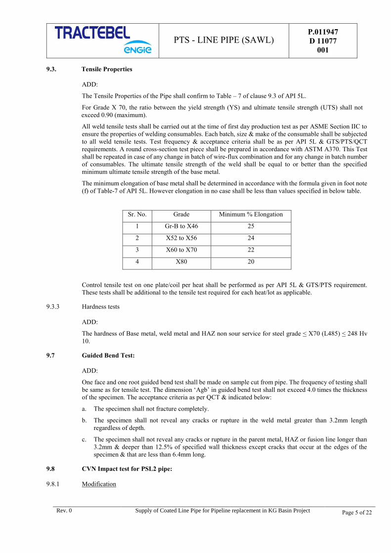
9.3. Tensile Properties
ADD:
The Tensile Properties of the Pipe shall confirm to Table – 7 of clause 9.3 of API 5L.
For Grade X 70, the ratio between the yield strength (YS) and ultimate tensile strength (UTS) shall not
exceed 0.90 (maximum).
All weld tensile tests shall be carried out at the time of first day production test as per ASME Section IIC to
ensure the properties of welding consumables. Each batch, size & make of the consumable shall be subjected
to all weld tensile tests. Test frequency & acceptance criteria shall be as per API 5L & GTS/PTS/QCT
requirements. A round cross-section test piece shall be prepared in accordance with ASTM A370. This Test
shall be repeated in case of any change in batch of wire-flux combination and for any change in batch number
of consumables. The ultimate tensile strength of the weld shall be equal to or better than the specified
minimum ultimate tensile strength of the base metal.
The minimum elongation of base metal shall be determined in accordance with the formula given in foot note
(f) of Table-7 of API 5L. However elongation in no case shall be less than values specified in below table.
Sr. No. Grade Minimum % Elongation
1 Gr-B to X46 25
2 X52 to X56 24
3 X60 to X70 22
4 X80 20
Control tensile test on one plate/coil per heat shall be performed as per API 5L & GTS/PTS requirement.
These tests shall be additional to the tensile test required for each heat/lot as applicable.
9.3.3 Hardness tests
ADD:
The hardness of Base metal, weld metal and HAZ non sour service for steel grade < X70 (L485) < 248 Hv
10.
9.7 Guided Bend Test:
ADD:
One face and one root guided bend test shall be made on sample cut from pipe. The frequency of testing shall
be same as for tensile test. The dimension ‘Agb’ in guided bend test shall not exceed 4.0 times the thickness
of the specimen. The acceptance criteria as per QCT & indicated below:
a. The specimen shall not fracture completely.
b. The specimen shall not reveal any cracks or rupture in the weld metal greater than 3.2mm length
regardless of depth.
c. The specimen shall not reveal any cracks or rupture in the parent metal, HAZ or fusion line longer than
3.2mm & deeper than 12.5% of specified wall thickness except cracks that occur at the edges of the
specimen & that are less than 6.4mm long.
9.8 CVN Impact test for PSL2 pipe:
9.8.1 Modification
PTS - LINE PIPE (SAWL)
P.011947
D 11077
001
Rev. 0 Supply of Coated Line Pipe for Pipeline replacement in KG Basin Project Page 6 of 22
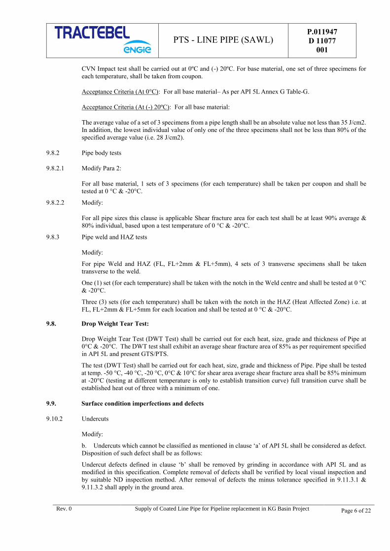
CVN Impact test shall be carried out at 0ºC and (-) 20ºC. For base material, one set of three specimens for
each temperature, shall be taken from coupon.
Acceptance Criteria (At 0°C): For all base material– As per API 5L Annex G Table-G.
Acceptance Criteria (At (-) 20ºC): For all base material:
The average value of a set of 3 specimens from a pipe length shall be an absolute value not less than 35 J/cm2.
In addition, the lowest individual value of only one of the three specimens shall not be less than 80% of the
specified average value (i.e. 28 J/cm2).
9.8.2 Pipe body tests
9.8.2.1 Modify Para 2:
For all base material, 1 sets of 3 specimens (for each temperature) shall be taken per coupon and shall be
tested at 0 °C & -20°C.
9.8.2.2 Modify:
For all pipe sizes this clause is applicable Shear fracture area for each test shall be at least 90% average &
80% individual, based upon a test temperature of 0 °C & -20°C.
9.8.3 Pipe weld and HAZ tests
Modify:
For pipe Weld and HAZ (FL, FL+2mm & FL+5mm), 4 sets of 3 transverse specimens shall be taken
transverse to the weld.
One (1) set (for each temperature) shall be taken with the notch in the Weld centre and shall be tested at 0 °C
& -20°C.
Three (3) sets (for each temperature) shall be taken with the notch in the HAZ (Heat Affected Zone) i.e. at
FL, FL+2mm & FL+5mm for each location and shall be tested at 0 °C & -20°C.
9.8. Drop Weight Tear Test:
Drop Weight Tear Test (DWT Test) shall be carried out for each heat, size, grade and thickness of Pipe at
0°C & -20°C. The DWT test shall exhibit an average shear fracture area of 85% as per requirement specified
in API 5L and present GTS/PTS.
The test (DWT Test) shall be carried out for each heat, size, grade and thickness of Pipe. Pipe shall be tested
at temp. -50 °C, -40 °C, -20 °C, 0°C & 10°C for shear area average shear fracture area shall be 85% minimum
at -20°C (testing at different temperature is only to establish transition curve) full transition curve shall be
established heat out of three with a minimum of one.
9.9. Surface condition imperfections and defects
9.10.2 Undercuts
Modify:
b. Undercuts which cannot be classified as mentioned in clause ‘a’ of API 5L shall be considered as defect.
Disposition of such defect shall be as follows:
Undercut defects defined in clause ‘b’ shall be removed by grinding in accordance with API 5L and as
modified in this specification. Complete removal of defects shall be verified by local visual inspection and
by suitable ND inspection method. After removal of defects the minus tolerance specified in 9.11.3.1 &
9.11.3.2 shall apply in the ground area.
PTS - LINE PIPE (SAWL)
P.011947
D 11077
001
Rev. 0 Supply of Coated Line Pipe for Pipeline replacement in KG Basin Project Page 7 of 22
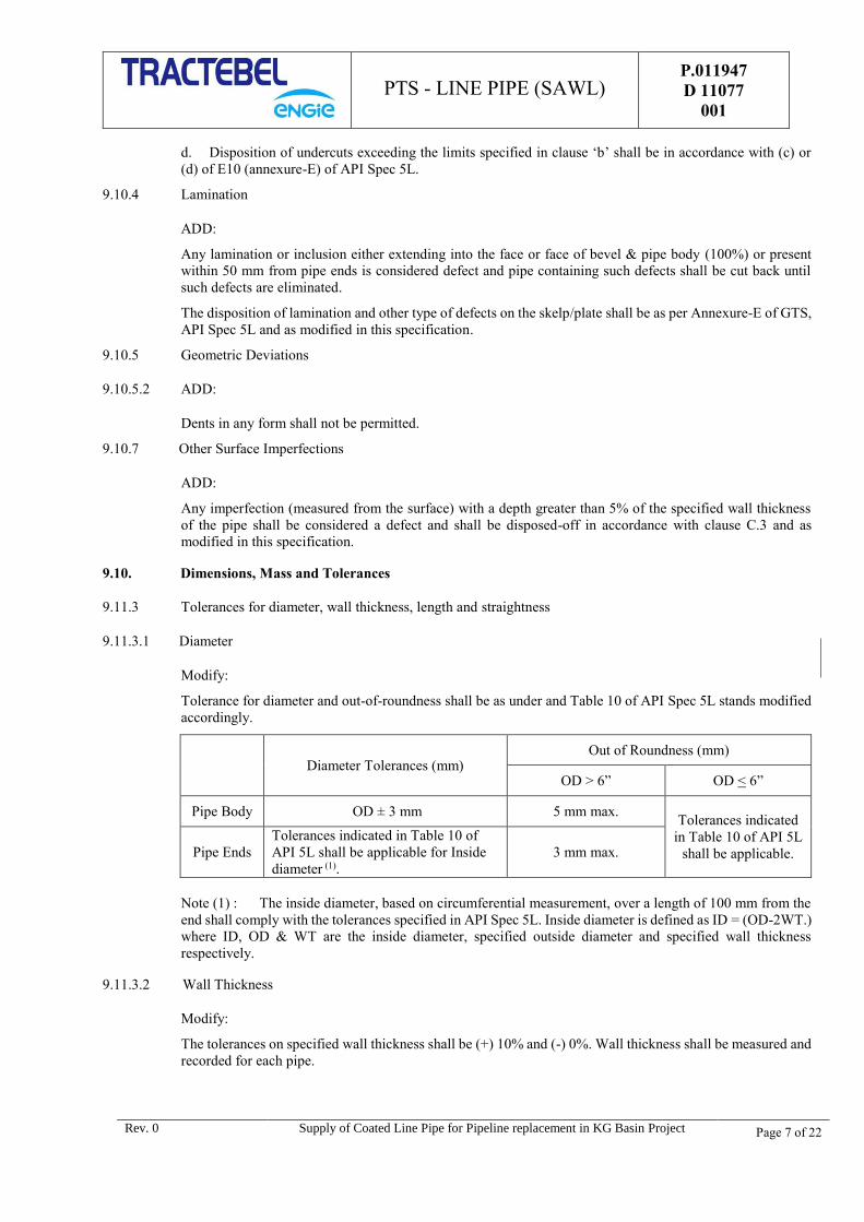
d. Disposition of undercuts exceeding the limits specified in clause ‘b’ shall be in accordance with (c) or
(d) of E10 (annexure-E) of API Spec 5L.
9.10.4 Lamination
ADD:
Any lamination or inclusion either extending into the face or face of bevel & pipe body (100%) or present
within 50 mm from pipe ends is considered defect and pipe containing such defects shall be cut back until
such defects are eliminated.
The disposition of lamination and other type of defects on the skelp/plate shall be as per Annexure-E of GTS,
API Spec 5L and as modified in this specification.
9.10.5 Geometric Deviations
9.10.5.2 ADD:
Dents in any form shall not be permitted.
9.10.7 Other Surface Imperfections
ADD:
Any imperfection (measured from the surface) with a depth greater than 5% of the specified wall thickness
of the pipe shall be considered a defect and shall be disposed-off in accordance with clause C.3 and as
modified in this specification.
9.10. Dimensions, Mass and Tolerances
9.11.3 Tolerances for diameter, wall thickness, length and straightness
9.11.3.1 Diameter
Modify:
Tolerance for diameter and out-of-roundness shall be as under and Table 10 of API Spec 5L stands modified
accordingly.
Diameter Tolerances (mm) Out of Roundness (mm)
OD > 6” OD < 6”
Pipe Body OD ± 3 mm 5 mm max. Tolerances indicated
in Table 10 of API 5L
shall be applicable. Pipe Ends
Tolerances indicated in Table 10 of
API 5L shall be applicable for Inside
diameter (1).
3 mm max.
Note (1) : The inside diameter, based on circumferential measurement, over a length of 100 mm from the
end shall comply with the tolerances specified in API Spec 5L. Inside diameter is defined as ID = (OD-2WT.)
where ID, OD & WT are the inside diameter, specified outside diameter and specified wall thickness
respectively.
9.11.3.2 Wall Thickness
Modify:
The tolerances on specified wall thickness shall be (+) 10% and (-) 0%. Wall thickness shall be measured and
recorded for each pipe.
PTS - LINE PIPE (SAWL)
P.011947
D 11077
001
Rev. 0 Supply of Coated Line Pipe for Pipeline replacement in KG Basin Project Page 8 of 22
9.11.3.3 Length
ADD:
All pipes shall be supplied with length between 11.5 m and 12.5 m. Thickness wise average length of pipes
shall be 12.0mm. The average length shall be cumulative as measured at pipe mill despatch note. For
mechanical sampling pipes, minimum length of 11.0 m is acceptable. The minimum average length of the
entire ordered quantity in any case shall be 12.0m.
API Spec 5L, clause no. 9.11.3.3 & Table 12 shall not be applicable. Overall length tolerance shall be (-) Zero
and (+) One pipe length to complete the ordered quantity.
9.12 Finish of Pipe Ends
9.12.1 The second sentence “Automatically, the 100 following shall apply” shall be read as :
“Automatically, the following shall apply”.
9.12.5 Plain Ends
ADD:
Pipes shall be furnished with Plain ends. Unless specified otherwise, the pipe ends shall be machine bevelled
as per API Spec. 5L.
In removing the inside burrs at the pipe ends, care shall be taken not to remove excess metal and not to form
an inside cavity or bevel. Removal of excess metal beyond the minimum wall thickness as indicated in para
9.11.3.2 of this specification, shall be a cause for re-bevelling. In case root face of bevel is less than that
specified, the pipe ends shall be re-bevelled and rectification by filing or grinding shall not be done.
9.13 Tolerance for the Weld Seam
9.13.1 Radial offset of strip edges
ADD:
All pipes shall be checked for offset of plate edges. Offset shall be measured and recorded at least 3 times per
operating shift (12 hours maximum).
9.13.2 Height of the Flash or Weld Bead / Reinforcement
ADD:
The maximum height of external weld bead shall be 0.5 mm to 3.2 mm max. and for internal weld bead shall
be 0.5 mm to 2.5 mm max. for all specified wall thickness. All pipes shall be checked for weld bead height
using a template having a cut out for weld bead / or by Bead height gauge and shall be measured and recorded
at least 3 times per operating shift (12 hours maximum).
9.13.3 Misalignment of the weld bends of SAW and COW pipes
Modify:
All pipes shall be checked for out-of-line weld bead and shall be measured and recorded at least 3 times per
operating shift (12 hours maximum). Checking of the weld seam misalignment shall also be carried out on
metallographic & macro graphic examination specimen as stated at and as modified in this specification.
10. INSPECTION
10.1.1 General
ADD :
In case of any contradiction between API 5L, GTS and PTS, the following order of priority shall be followed.
PTS - LINE PIPE (SAWL)
P.011947
D 11077
001
Rev. 0 Supply of Coated Line Pipe for Pipeline replacement in KG Basin Project Page 9 of 22
1. Quality Control Table (QCT).
2. Particular Technical specification (PTS).
3. General Technical Specification (GTS).
4. API 5L.
This document shall read in conjunction with tender QCT / GTS / API 5L / relevant standards and codes.
ADD in Para 3:
Single TPIA shall be appointed by pipe manufacturer at steel mill & pipe mill for material inspection and
certification as per project requirements.
The QCT for Steel HR Plates/Coils shall be prepared by the Steel Manufacturer as per actual requirements
specified in the bid document, line pipe specification & QCT. The same shall be submitted for
Owner/Consultant’s approval. Testing of Raw material (Steel HR Plates/Coils) at steel mill shall be witness
by TPIA.
ADD:
Testing Frequency: The frequency for all the tests shall be strictly as per the QCT attached with this
specification. In case of any conflict in requirements of QCT and PTS/GTS & API 5L, the more stringent
requirement shall prevail.
10.2 Specific Inspection
10.2.1 ADD:
Sampling Frequency
The manufacturer shall carry out analysis of two samples per 50 pipes representing each heat of steel used for
production of pipes.
Product analysis shall be carried out from finished pipe. The specimen shall be taken from finished pipe.
10.2.5 Macrographic and Metallographic Tests
ADD:
A test specimen for metallographic shall be taken transverse to the weld from one finished pipe from each lot
per heat or at least once per operating shift whichever is stringent.
The specimen shall be suitably ground, polished and etched to reveal the macro structure. The specimen shall
be visually examined using a minimum 10X magnification to facilitate proof that proper fusion has been
achieved for the full thickness and there is proper interpretation of passes, their alignment and texture of
welding zone. Grain size shall be 7 or finer as per ASTM E112.
10.2.6 Hydrostatic Test
Hydrotest shall be carried out after cold expansion.
The hydrotest pressure shall be such that hoop stress generated is at least 95% of SMYS of the Pipe Material,
computed based on the formula mentioned in API Spec 5L. Test pressure shall be held for a minimum period
of 15 seconds.
Duly calibrated pressure gauge shall be installed both at the test bay as well as at the control cabin and
graphical records with respect to both the pressure gauges shall be maintained for each pipe.
The test pressure measuring device shall be calibrated by means of a dead weight tester, or equivalent at the
beginning of each shift.

PTS - LINE PIPE (SAWL)
P.011947
D 11077
001
Rev. 0 Supply of Coated Line Pipe for Pipeline replacement in KG Basin Project Page 10 of 22
Pressure gauge range shall have a minimum range of 1.5 times and maximum 4 times of test pressure. The
pressure gauges used should have a minimum least count of 2 kg/ cm2. Calibration of pressure gauge shall
be done at start of an each shift (12 hours max.). Accuracy of pressure gauges used shall be within 1% FSD
(full scale deflection).
Information to Bidders
In case manufacturer so desires, he will be advised at least 2 weeks in advance so that his representative may
witness the hydrostatic test in field. However, the testing & leak finding (if any) and repair operation shall
not be postponed for the absence of manufacturer’s representative.
10.2.10 Non Destructive Inspection
ADD:
Base Material Inspection:
Ultrasonic testing shall be carried out for 100% area of Plates/Coils during manufacturing of pipes.
10.2.11 Reprocessing shall not be permitted.
10.2.12 Deleted
11. MARKING
11.2 Pipe Marking
Paint used for stencil marking shall withstand upto 250 °C expected to be experienced during further external
anti-corrosion coating operations of line pipe by coating applicator.
Stencil marking on the outside and inside surface of pipe on both sides shall be used for marking on pipes.
The marking of finished line pipe should also contain the Pipe No, Heat No, coated pipe No, Inspection mark
by TPI, Diameter of pipe and wall thickness(to be marked in white color).
A colour band of 50 mm width to differentiate thickness of pipes shall be provided at inside at each extremity
(150mm from the end) of the pipe by the pipe manufacturer.
In addition to the marking requirements of GTS, the coater shall also transfer the marking details appearing
on the bare pipe.
Bar code shall be provided as per the requirements of PTS for application. Bar coding procedure shall be
submitted by pipe manufacturer for Purchaser, Owner / Consultant approval.
11.2.2 Modify para / bullet#2: Die Stamping with Low stress dot punch only shall be allowed on pipe surface OD
on each accepted pipe.
12. COATING AND END PROTECTION
12.1 Coating
The pipes shall be coated externally & internally. The Coating shall in line with the requirements of the GTS
for Pipeline Coating (740 GTS 404 Rev.0) and following documents:
External 3LPE Coating – as per PTS – Line pipe External coating - P.011947 D 11077 004
Internal Epoxy Coating – as per PTS – Line pipe Internal coating - P.011947 D 11077 005
12.2 End Protectors
ADD:
PTS - LINE PIPE (SAWL)
P.011947
D 11077
001
Rev. 0 Supply of Coated Line Pipe for Pipeline replacement in KG Basin Project Page 11 of 22
Pipe Bevel ends shall be protected using Metallic Bevel protectors as per Manufacturer's standard, to be
supplied by Pipe Manufacturer. In addition, Plastic end caps, mentioned in the GTS, are not required for pipes.
Bevel protectors shall be of a design such that they can be re-used by coating applicator for providing on anti-
corrosion coating of line pipe.
14. PIPE LOADING
In case of Indian Manufacture/Supplier - The Loading, Unloading and Transportation of Pipes on Trailer
(for final transportation to the site) shall be in the scope of the Pipe Manufacturer.
In case of foreign manufacturer/supplier – Pipes will be despatched to Indian port as per terms and
conditions of contract.
Pipe Manufacturer shall ensure that there is no damage of any kind to the Pipes before despatch. Any
defect/damage detected in Pipe before or during loading to the Trailer /Marine Vessel shall be rectified by the
Manufacturer as per the requirements of the code. The TPIA can reject the pipe, if found not conforming to
the requirements of the codes and GTS/PTS/QCT.
Pipes supplied from Foreign manufacturer/supplier :
The manufacturer/supplier shall submit calculations and sketch for loading/unloading & stacking at all points,
e.g. pipe yard, trailers, warehouse at port before loading on ship, on the ship for the sea journey & on trailer
at port as per API RP 5LW.
Pipes supplied from Indian manufacturer:
The manufacturer shall submit calculations and sketch for loading/unloading & stacking at all points, e.g.
Supplier’s Warehouse (ex-works) before loading on the trailers as per API RP 5L1.
The Transportation, Unloading & Stacking of Coated Line Pipes at GAIL’s storage yard located at
Rajahmundry (Andhra Pradesh) and Vijaipur (MP) shall be in the scope of the Pipe Manufacturer including
arrangement & maintenance of storage yard near Rajahmundry (Andhra Pradesh), as per the tender terms &
conditions.
The manufacturer shall submit calculations and sketch for loading/unloading & stacking at all points, e.g.
Supplier’s Warehouse (ex-works) before loading on the trailers as per API RP 5L1.
ADD:
Manufacturer shall get written approval from Owner/Owner’s representative for the acceptable stacking
height for Line Pipe before storage in Warehouse / dump yard.
Pipes shall be stacked using wooden blocks or other suitable separator strips.
The Manufacturer shall be responsible for any damage occurring to the pipes during loading / unloading
and transportation by the relevant transportation means.
Line Pipe Manufacturer shall ensure that no bevel protectors can be lost during transportation.
The Manufacturer shall provide a description with calculation of the handling, storage and transportation
procedures during the total manufacturing cycle.
The Manufacturer shall provide description with calculation of long period (> 4 months) storage
procedure, including the number and spacing of bearing strips and the number of layers.”
The Manufacturer shall consequently:
Inspect the bare pipes upon delivery to check that they have suffered no previous damage.
All repairs and inspections shall be at the Manufacturer expense.
The pipes shall be handled without causing damage to the pipe bevels and coating.
PTS - LINE PIPE (SAWL)
P.011947
D 11077
001
Rev. 0 Supply of Coated Line Pipe for Pipeline replacement in KG Basin Project Page 12 of 22
Direct contact with steel or hemp slings or with any material whose shape or nature may deteriorate the
pipe coating shall be strictly prohibited. Polyamide slings or hooks fitted with thermoplastic protection
shall be used.
During transportation, the longitudinal weld of SAW pipes shall be on the upper quadrant.
The manufacturer shall submit calculations and sketch for loading/unloading & stacking at all points.
16. ONLINE PIPE TRACKING DATA (NEW CLAUSE)
The pipe manufacturer shall establish and follow procedures for maintaining heat and lot identity of all pipes
during production. Also, it is required to have traceability of each day production.
In order to establish traceability of pipes, the system should have minimum of following information:
Heat / Coil Number
Traceability of pipe at each station
Final status of pipe
Reason for each rejection
Σ Σ Σ
PTS - LINE PIPE (SAWL)
P.011947
D 11077
001
Rev. 0 Supply of Coated Line Pipe for Pipeline replacement in KG Basin Project Page 13 of 22
THE FOLLOWING ANNEXURES OF API 5L 45TH EDITION, ARE APPLICABLE FOR PIPES
MANUFACTURED AS PER THIS PTS :
Annex B
(normative)
Manufacturing procedure qualification for PSL 2 pipe
In addition to the requirements given in GTS, all the requirements given in QCT attached with this specification, for first
day production, shall be applicable for the Pipe.
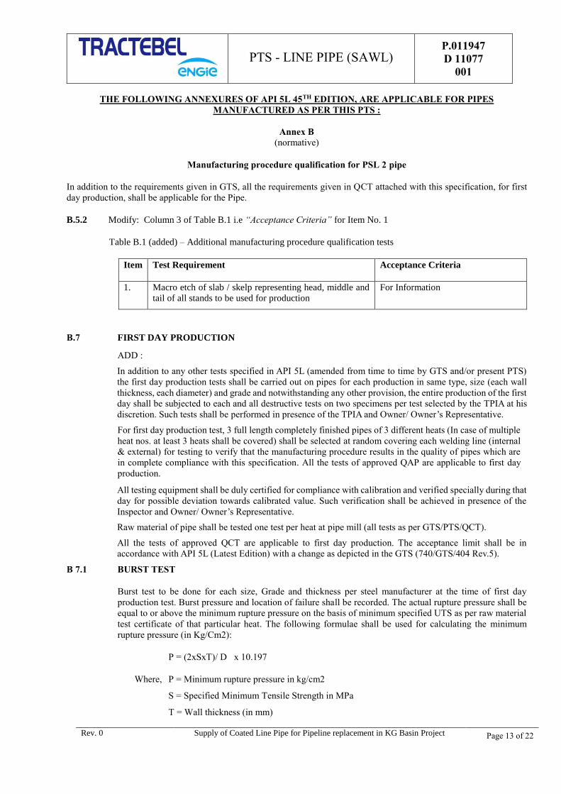
B.5.2 Modify: Column 3 of Table B.1 i.e “Acceptance Criteria” for Item No. 1
Table B.1 (added) – Additional manufacturing procedure qualification tests
Item Test Requirement Acceptance Criteria
1. Macro etch of slab / skelp representing head, middle and
tail of all stands to be used for production
For Information
B.7 FIRST DAY PRODUCTION
ADD :
In addition to any other tests specified in API 5L (amended from time to time by GTS and/or present PTS)
the first day production tests shall be carried out on pipes for each production in same type, size (each wall
thickness, each diameter) and grade and notwithstanding any other provision, the entire production of the first
day shall be subjected to each and all destructive tests on two specimens per test selected by the TPIA at his
discretion. Such tests shall be performed in presence of the TPIA and Owner/ Owner’s Representative.
For first day production test, 3 full length completely finished pipes of 3 different heats (In case of multiple
heat nos. at least 3 heats shall be covered) shall be selected at random covering each welding line (internal
& external) for testing to verify that the manufacturing procedure results in the quality of pipes which are
in complete compliance with this specification. All the tests of approved QAP are applicable to first day
production.
All testing equipment shall be duly certified for compliance with calibration and verified specially during that
day for possible deviation towards calibrated value. Such verification shall be achieved in presence of the
Inspector and Owner/ Owner’s Representative.
Raw material of pipe shall be tested one test per heat at pipe mill (all tests as per GTS/PTS/QCT).
All the tests of approved QCT are applicable to first day production. The acceptance limit shall be in
accordance with API 5L (Latest Edition) with a change as depicted in the GTS (740/GTS/404 Rev.5).
B 7.1 BURST TEST
Burst test to be done for each size, Grade and thickness per steel manufacturer at the time of first day
production test. Burst pressure and location of failure shall be recorded. The actual rupture pressure shall be
equal to or above the minimum rupture pressure on the basis of minimum specified UTS as per raw material
test certificate of that particular heat. The following formulae shall be used for calculating the minimum
rupture pressure (in Kg/Cm2):
P = (2xSxT)/ D x 10.197
Where, P = Minimum rupture pressure in kg/cm2
S = Specified Minimum Tensile Strength in MPa
T = Wall thickness (in mm)

PTS - LINE PIPE (SAWL)
P.011947
D 11077
001
Rev. 0 Supply of Coated Line Pipe for Pipeline replacement in KG Basin Project Page 14 of 22
D = OD in mm
Burst test pressure shall be such that hoop stress generated is equivalent to 125% of SMYS (minimum). Burst
test pressure & location shall be recorded. If burst pipe fails below 125% of SMYS then manufacture shall
investigate the root cause & submit the report to the client before retesting & restarting of the regular
production.
B 7.2 VISUAL EXAMINATION
Each pipe shall be checked for visual defect and dimensional checks as per QCT / approved QAP.
B 7.3 NDT EXAMINATION
B 7.3.1 Ultrasonic Testing
Ultrasonic testing shall be done after 24 hrs. of submerged arc welding.
B 7.3.2 Radiographic Examination
Selected Pipes for First Day Production test shall be radiographed for full length of weld. The acceptance
limit shall be in accordance with API 5L (Latest Edition) with a change as depicted in the GTS (740/GTS/404),
QCT / approved QAP.
B 7.3.3 Residual Magnetism
Residual Magnetism shall be as per Cl. E.7 of this specification.
B 7.4 PHYSICAL TESTING
In addition to the following test, other tests specified in QCT /approved QAP shall be carried out on 2 samples:
All Weld Tensile Test
Chemical Test
Tensile Test for pipe base & weld (Transverse & Longitudinal)
Guided bend test (Root & Face),
Impact test
Macro and micro examination,
Hardness test
Drop weight tear test
All destructive tests on two specimens per test selected.
Annex C (normative) : Treatment of surface imperfections and defects
C.4.2 ADD:
o) Repair of pipe body by welding is not permitted.
p) The defective part of the weld shall be clearly marked on the pipe so that the defect can be easily located
and repaired. Approval for each repair shall be taken from TPIA before proceeding further.
q) Repaired welds shall be inspected both by X-ray and UT.
r) Repair welding on parent metal is not permitted.
s) Repair after Cold Expansion is not permitted.
t) The weld repairs shall have minimum length of 100mm, even if the defect is of lesser extent.
Annex D (normative) : Repair welding procedure

PTS - LINE PIPE (SAWL)
P.011947
D 11077
001
Rev. 0 Supply of Coated Line Pipe for Pipeline replacement in KG Basin Project Page 15 of 22
Annex E (normative) : Non-destructive inspection for other than sour service or offshore service
Following standards have been replaced by new standards:
Standard mentioned in GTS New Standard
ISO 10124, ISO 12094, ISO 9303, ISO
9305, ISO 11496
ISO 10893-8, ISO 10893-9, ISO 10893-10
SEL 072-77 EN 10160
ISO 13665 ISO 10893-5
ISO 12095 ISO 10893-4
E.1 QUALIFICATION OF PERSONNEL
Modify Para 1:
All personnel performing NDT activities shall be qualified in the technique applied, in accordance with latest
edition of ISO 11484 or ASNT SNT-TC-1A or equivalent.
Staff in charge with the NDT shall be duly qualified according to International Standards like, but not limited
to:
The American Standard ASN-TC-1A (published by the ASNT) and all Codes it refers to, at least one
UT-Level III shall be available with Manufacturer.
European Standard «EN 473» titled « Non-destructive testing - Qualification and certification of NDT
personnel - General principles» and all the Codes it refers to.
At least one no. of ASNT Level III inspector shall be made available by the manufacturer on permanent basis
(for 24 hrs) during all production at Manufacturer’s works.
E.2.1 Automatic Straight Beam UT inspection
ADD:
The height of indication having amplitude beyond the reference accepted signal height (100% at 80% FSH)
is considered as defective indication. Locations showing indications above the acceptance limits may be re-
examined by manual ultrasonic method. Acceptance criteria, Calibration standard & Frequency shall be as
per QCT for both automatic & Manual UT.
E.2.2 Automatic Angle Beam UT inspection
ADD:
Ultrasonic and Electromagnetic Inspection Reference Standards
The reference standard (calibration pipe) shall have the same specified diameter and wall thickness as
specified for the production pipe being inspected and shall be of sufficient length to permit calibration of
ultrasonic inspection equipment at the speed to be used in normal production. The reference standard
(calibration pipe) shall also be of the same material, type and have the same surface finish as the pipe being
inspected.
The reference standard for weld UT shall contain machined notches/holes as given below:
- Two longitudinal inside notches of type N5 at both edges of weld seam.
- Two longitudinal outside notches of type N5 at both edges of weld seam.
- Two longitudinal notches of type N5 at the centre of the weld seam, one outside and one inside.
- Two transverse notches of type N5 across the weld seam, one outside and one inside.
- A drilled hole in the centre of the weld seam, of diameter equal to 1.6 mm.

PTS - LINE PIPE (SAWL)
P.011947
D 11077
001
Rev. 0 Supply of Coated Line Pipe for Pipeline replacement in KG Basin Project Page 16 of 22
Reference standard for the ultrasonic inspection of Plate/Coil & plate edges/pipe ends shall be as per QCT.
The calibration shall be performed at following intervals:
a) At the beginning of each operating shift (12 hours maximum) and subsequently every 4 hours.
b) Every time there is change in probes or working condition of the UT machine.
c) Every time the running of the system gives rise to doubts on its efficiency.
If during the above calibration verification, it is found that the equipment has not functioned satisfactorily in
the opinion of the Owner/Owner's Representative/TPIA, all the pipes or skelp already inspected after the
previous verification shall be inspected again at Manufacturer's cost.
E.3.1.4 Manual Ultrasonic Testing (MUT)
E.3.1.4.5 ADD:
The weld at any pipe ends not covered by automatic ultrasonic equipment shall be inspected by manual
ultrasonic equipment with same sensitivity and capability as automatic equipment.
E.3.1.4.6 ADD:
Full circumference of both ends of each pipe shall be 100% manual ultrasonically tested over a circumferential
width of at least 100 mm with angular probes to detect cracks. In case of non-availability of angular probes
at the mill, the full circumference of both ends of each pipe shall be inspected with magnetic particle technique
over a circumferential width of at least 100 mm to detect surface cracks.
E.4 RADIOGRAPHIC INSPECTION OF WELD SEAMS
ADD:
Real Time Radiography (Fluoroscopy) shall be as per QCT.
E.5 ULTRASONIC AND ELECTROMAGNETIC INSPECTION
Add:
Base Material Inspection - Ultrasonic testing shall be carried out for 100% area of coil/plate during
manufacturing of pipes.
E.5.4.3 Add:
General
Calibration of Testing Equipment
All equipment used for non-destructive inspection shall be checked for possible deviation towards its calibrated
value(s). The following check shall be performed:
at the start & end of every working shift or at the time of running if any doubt arises.
at every change-over of an equipment operator,
at the start and end of a production shift,
every time the running of the testing system is interrupted or when any doubt arises, Whichever occurs
first.
If on checks of the testing systems, the calibration requirements are not satisfied (even after increasing the
sensitivity for ultra-sonic equipment by 3db for allowance to system drift), then all pipes lengths tested after the
previous equipment check shall be retested after the testing system has been recalibrated.
E.6 MAGNETIC PARTICLE INSPECTION
ADD:

PTS - LINE PIPE (SAWL)
P.011947
D 11077
001
Rev. 0 Supply of Coated Line Pipe for Pipeline replacement in KG Basin Project Page 17 of 22
Each pipe end upto 300 mm, OD weld seam, ID weld seam & both the bevel end shall be magnetic particle
inspected as per QCT. Full OD weld seam of five pipes per shift shall be magnetic particle inspected. In case
no indications are observed in the first three shifts the frequency will be reduced to one pipe per shift.
Acceptance limit, Calibration standard & Calibration frequency shall be as per QCT.
E.7 Residual Magnetism
ADD:
The residual magnetic field created by ultrasonic or electromagnetic scanning device shall be released and
such residual magnanimity shall be inspected and accepted by TPIA and/ or Owner/ Owner’s Representative.
The average of the four readings shall not exceed 20 Gauss and no reading shall exceed 25 gauss when
measured with a hall-effect gauss meter, or equivalent values when measured with other type of instruments.
Annex G (normative) : PSL 2 pipe with resistance to ductile fracture propagation
Table G – Minimum CVN absorbed energy requirements
Specified
outside
diameter,
D
Mm (inch)
Full-size CVN average absorbed energy, Minimum
KvT a,b (J)
B to X42 > X42 to
X46
> X46 to
X52 > X52 to
X56 > X56 to
X60 > X60 to
X65 > X65 to
X70
457.0 (18) 40 40 40 40 40 45 50
508.0 (20) 40 40 40 40 42 47 53
610.0 (24) 40 40 40 41 46 51 58
711.0 (28) 40 40 40 45 49 56 62
813.0 (32) 40 40 42 48 53 59 66
914.0 (36) 40 40 45 51 56 63 70
1016.0 (40) 40 40 47 54 59 66 74
1118.0 (44) 40 42 50 56 62 70 78
1219.0 (48) 40 44 52 59 64 73 81
a The required KvL (longitudinal direction specimens) values shall be 50% higher than the required KvT
values for BM, weld and HAZ.
b Testing shall be performed at a temperature of 0 °C (32 °F) or at a lower temperature as specified in the
purchase order.
c For intermediate specified outside diameter, CVN average absorbed energy value (KvT) shall be same
value as given in the table for next higher specified outside diameter.
Annex J (normative) : PSL 2 pipe ordered for offshore service
Annex K (normative) : Non-destructive inspection for pipe ordered for sour service and/or offshore service
Annex O (informative) : Use of the API Monogram by Licensees
Annex P (informative) : Equations for Threaded and Coupled Pipe and Background Equations for Guided
Bend and CVN Test Specimens.
In Addition:
PTS - LINE PIPE (SAWL)
P.011947
D 11077
001
Rev. 0 Supply of Coated Line Pipe for Pipeline replacement in KG Basin Project Page 18 of 22
The following Annexures of ‘GTS’ (Doc No: 740 GTS 404) shall be applicable:
Annex K (normative) : Annexure ‘K’ of ‘GTS’ (Doc No: 740 GTS 404) shall be followed, in view of the rigorous
requirement of AUT of weld seam specified therein.
Annexure Q of GTS : ‘Purchaser Indicative Inspection and Quality Plan’, has been replaced by QCT for Line
pipes (SAWL) attached with this specification. The same shall be applicable for SAWL
Line pipes.
Z-Z-Z
PTS - LINE PIPE (SAWL)
P.011947
D 11077
001
Rev. 0 Supply of Coated Line Pipe for Pipeline replacement in KG Basin Project Page 19 of 22
APPENDIX 1
TECHNICAL QUESTIONNAIRE FOR EVALUATION OF THE BIDS
1. Scope
Grade X70, Pipe ND – 18” – External (3LPE) & Internal (Epoxy) coated line Pipe as specified in MR.
Applicable Documents:
API 5L fourty-five Edition, December, 2012
Tractebel Specifications (PTS, GTS) & documents.
The information requested below shall be answered fully and wherever required necessary attachments
must be added. All information shall be relevant to the scope of the tender as stated above. No blank
space shall be left. If the part is not applicable, it should be written so.
2. General Information
2.1. Organization
Give a detailed description (organization structure, number of technical (job specific) people, facilities,
equipment, …..).
Concerning:
Overall Structure of the organization
…………………………………………………………………………………………
…………………………………………………………………………………………
Line Pipe production facilities and capacities:
…………………………………………………………………………………………
…………………………………………………………………………………………
Laboratories ( in-house or sub-contractor):
…………………………………………………………………………………………
…………………………………………………………………………………………
QA and/or QC department:
…………………………………………………………………………………………
…………………………………………………………………………………………
Non Destructive Testing department ( in-house or subcontractors )
…………………………………………………………………………………………
…………………………………………………………………………………………
R&D department ( In house or Research Institutes )
…………………………………………………………………………………………
…………………………………………………………………………………………
Other relevant departments or services ( In house or subcontractors )
…………………………………………………………………………………………
…………………………………………………………………………………………
2.2. Certificates and Approvals
Give type of approvals, date of issue and validity, for the scope of present tender
ISO certification ( ISO 9001 - 2015)
PTS - LINE PIPE (SAWL)
P.011947
D 11077
001
Rev. 0 Supply of Coated Line Pipe for Pipeline replacement in KG Basin Project Page 20 of 22
……………………………………………………………………………………….
……………………………………………………………………………………….
API approvals
………………………………………………………………………………………
………………………………………………………………………………………
Safety approvals
………………………………………………………………………………………
………………………………………………………………………………………
Third party approvals
………………………………………… …………………………………………..
……………………………………………………………………………………….
Client approvals
………………………………………… …………………………………………
………………………………………… …………………………………………
Other approvals
……………………………………………………………………………………
……………………………………………………………………………………
2.3. References for the manufacture/supply of API 5L X70 or above, Line pipe and coating separately for each
part
Give for the last five years
- Name of client or project (eventually name of contact person)
- Number of kilometers produced
- Inspection Agency (eventually name of contact person)
Year 2013 :
…………………………………………………………………………..
…………………………………………………………………………..
Year 2014 :
…………………………………………………………………………..
…………………………………………………………………………..
Year 2015:
…………………………………………………………………………..
…………………………………………………………………………..
Year 2016:
…………………………………………………………………………..
…………………………………………………………………………..
Year 2017 :
…………………………………………………………………………..
…………………………………………………………………………..
Year 2018 (eventually orders to be executed remainder of the year)
…………………………………………………………………………..
…………………………………………………………………………..
3. Fabrication and Inspection Procedures

PTS - LINE PIPE (SAWL)
P.011947
D 11077
001
Rev. 0 Supply of Coated Line Pipe for Pipeline replacement in KG Basin Project Page 21 of 22
3.1 Give a detailed description of the fabrication process utilized for these types of pipes
Forming (how many steps).
Body testing
Cold expansion or other intervention
Type of testing along the line
Maximum length of pipe that can be supplied for pipe sizes as per MR.
3.2 Give a detailed description of the production line(s), including type and location of the testing facilities.
Explain all relevant operations which you consider important for obtaining a high quality product.
3.3 Provide a relevant example (which will be applicable in case of an order) of a LOFC (List of fabrication and
control) as specified in ANNEX B of the GTS.
3.4 Provide a copy of all relevant NDT procedures (including acceptance criteria) that will be utilised in case of
an order, such as UT, RX, MT, PT, …….
3.5 Provide a list of the NDT personal, with their qualifications in each technique (Level 1, 2 or 3 according to
ASNT or other qualification authority) Specify if these operators are on your pay-roll or from a sub supplier.
3.6 Provide a copy of the applicable external coating procedures, including the preparation of the pipes before
coating.
3.7 Provide a copy of the applicable marking procedure.
3.8 Provide a list of all equipment used for the mechanical testing, chemical analysis (in house or subcontractors)
and tools for dimensional controls, including the date of calibration and the validity period of these
calibrations.
3.9 Provide your procedure concerning “Control of non-conforming products” and the procedure concerning
“Corrective and Preventive Actions” (See ISO 9001:2015).
4. Material Suppliers
4.1 Provide commitment letter from at least two possible plate/coils suppliers (from purchaser’s approved vendor
list).
4.2 Provide a procedure or any other document, which gives details concerning the characteristics of the material,
production controls, testing, certificates….required by you.
4.3 Provide a procedure or any other document, which gives details concerning the incoming testing and controls
of these materials, performed by your QA/QC department.
4.4 Provide your procedure concerning Supplier Evaluation (section 7.4 of ISO 9001:2015), detailing the controls
(audits?) performed on your suppliers. Also provide a copy of the planning of your supplier audits for last
three years.
5. Conformity with the requirements
Please confirm specifically that you will be confirming to the requirements stipulated in these tender
documents.
The issues in particular under consideration are:
Materials
- Chemical composition and analysis
- Mechanical properties and testing requirements
- Dimensions and tolerances
Hydrostatic Testing
Marking

PTS - LINE PIPE (SAWL)
P.011947
D 11077
001
Rev. 0 Supply of Coated Line Pipe for Pipeline replacement in KG Basin Project Page 22 of 22
Inspection
- Inspection procedure
- Personnel qualifications
External coating
Procedures and reports
The supplier must testify that all information given is correct and complete, and that they agree with an
eventual audit of these issues by purchaser, a designated auditing company and/or the appointed Inspection
Agency.
The reply to this questionnaire must be dated and validated by a company stamp, and signed by a responsible
person according to the rules of the companies Quality Management System.
All information given by the company will be treated by TRACTEBEL as confidential information and will
only be used for technical evaluation of the companies tender for the supply of line pipes for this Pipeline
project.

PTS - LINE PIPE (SAWH)
P.011947
D 11077
002
PIPELINE REPLACEMENT IN KG BASIN PROJECT
TRACTEBEL ENGINEERING PVT. LTD.
PARTICULAR TECHNICAL SPECIFICATION –
LINE PIPES -
SUBMERGED ARC HELICAL WELDING (SAWH) - 18”
DOC. NO. P.011947-D-11077-002
0 29.04.2019 Issued for Procurement Rajveer Panwar Nirjhar Chakrabarti SK Hussain
Rev. Date Description Prepared by Checked by Approved by
PTS - LINE PIPE (SAWH)
P.011947
D 11077
002
Rev. 0 Supply of Coated Line Pipe for Pipeline replacement in KG Basin Project Page 1 of 20
TABLE OF CONTENTS
A. INTRODUCTION ................................................................................................................. 1
B. PROPERTIES OF THE PIPES ............................................................................................... 1
AMENDMENTS TO THE GTS .............................................................................................................. 2
3. NORMATIVE REFERENCES ................................................................................................. 2
4. TERMS AND DEFINITIONS ................................................................................................. 2
6. PIPE GRADE, STEEL GRADE AND DELIVERY CONDITION.................................................. 3
7. INFORMATION TO BE SUPPLIED BY THE CLIENT .............................................................. 3
8. MANUFACTURING .............................................................................................................. 3
9. ACCEPTANCE CRITERIA ..................................................................................................... 4
10. INSPECTION....................................................................................................................... 8
11. MARKING ......................................................................................................................... 11
12. COATING AND END PROTECTION .................................................................................... 11
14. PIPE LOADING ................................................................................................................. 11

PTS - LINE PIPE (SAWH)
P.011947
D 11077
002
Rev. 0 Supply of Coated Line Pipes for Pipeline replacement in KG Basin Project Page 1 of 22
A. INTRODUCTION
The present « Particular Technical Specification (PTS) » relates to the manufacture of "SAWH (Submerged
Arc Helical Welded) Steel Line Pipes" for GAIL INDIA LIMITED (GAIL) for the pipeline replacement in
KG Basin project for the service of natural gas.
The present Specification shall be read in conjunction with General Technical Specification 740/GTS/404
Rev. 5 (the GTS) and API 5L 45th edition which it amends and/or complements. A new edition of API
5L: “Fourty Sixth Edition, April 2018” will become effective from May 2019. Thus this new edition of
API 5L is the governing standard for purchase of line pipe. All clauses of new edition and tests should be
followed scrupulously.
The clauses of the present PTS & GTS are either more stringent or supplementary to the API 5L
requirements, and confirm, complete or modify certain sections/paragraphs of API 5L. All these clauses
will be followed scrupulously.
The present specification can confirm, complete or modify certain sections/paragraphs of said «General
Technical Specification». The PTS will govern the requirements for all such sections. Clauses of GTS
specification, which are not mentioned in PTS, remain unaltered and are fully applicable.
The manufacturer shall have a valid license to use API Monogram in accordance with the requirements of
API 5L Specification, 46th edition on line pipe as Product Specification Level (PSL) 2.
Only the clauses of present PTS & GTS which are more stringent or supplementary to the API 5L new
edition will prevail.
B. PROPERTIES OF THE PIPES
The Properties of Pipes manufactured as per this PTS, shall be as listed below:
Product Specification Level : PSL 2 as per API 5L
Design Pressure : 92 barg
Operating Temperature : 0 - 55 °C
Design temperature
Underground Services : (-) 20 °C to 60 °C
Aboveground Services : (-) 20 °C to 65 °C
Steel grade : Refer below Table 1
Pipe Size & Wall Thickness (Minimum) : Refer below Table 1
Length of the Pipes : Length of Pipe supplied shall be as per Clause 9.11.3.3
of this document. Overall length tolerance shall be (-)
Zero and (+) One pipe length to complete the ordered
quantity.
Table: 1
Sr.
No.
Outside Dia.
(Inch)
Material Grade as per
API 5L, PSL 2
Minimum Wall
thickness (mm) Quantity (M)
1. 18” API 5L X-70M 11.1 8000
2. 18” API 5L X-70M 12.7 7500
3. 18” API 5L X-70M 14.3 780
Calculation according to ASME B 31.8 with following notes:
PTS - LINE PIPE (SAWH)
P.011947
D 11077
002
Rev. 0 Supply of Coated Line Pipes for Pipeline replacement in KG Basin Project Page 2 of 22
Negative tolerance for WT = ZERO mm (0 mm).
Corrosion allowance = 2.0 mm (for 18” Main Line Pipe)
Specified Minimum Yield strength (SMYS) = 485 MPa (Gr. X70M)
Weld efficiency level = 100%.
AMENDMENTS TO THE GTS
The present specification has to be read in conjunction with the specification API 5L, 45th edition, and the
GTS. All the Clause nos. mentioned below, correspond to the respective Clause nos. of the API 5L, 45th
edition and of the GTS.
3. NORMATIVE REFERENCES
ADD :
API 5L Specification for Line pipe (46th Edition, April 2018).
API RP 5L3 Recommended Practice for Conducting DWTT on Line Pipe.
ASME V Boiler and Pressure Vessel Code, Section V Non Destructive Examination
ASME IX Welding and Brazing Qualifications (Boiler and Pressure Vessels Codes).
ASTM A 370 Standards Method and Definitions for Mechanical Testing of Steel Products.
ASTM E 112 Standard Methods for Determining Average Grain Size.
ASTM A 578 Standard Specification for Straight-beam Ultrasonic Examination of Plain and
Clad Steel Plates for Special Application.
ASTM E 23 Notched Bar Impact Testing of Metallic Materials.
AWS A5.17 Specification for Carbon Steel Electrodes and Fluxes for Submerged Arc
Welding.
BS 672 Wet Magnetic Particle inspection.
EN 10204 Metallic Products - Types of inspection Documents.
4. TERMS AND DEFINITIONS
ADD:
GTS means “ General Technical Specification 740/GTS/404 Rev.5 ” and all
documents it refers to.
PTS means the present “ Particular Technical Specification - P.011947 D
11077 002 ” and all its appendices, if any.
OWNER Shall mean “ GAIL INDIA LIMITED (GAIL) ”, being the Purchaser of
Line Pipes.
CONSULTANT /
OWNER’s
REPRESENTATIVE
Shall means “ TRACTEBEL Engineering pvt. ltd. ” / The company
nominated by the owner to design the natural gas transport or distribution
system and to specify the equipment.
TPIA means the Third Party Inspection Agency.
MANUFACTURER means the Manufacturer of the pipes as well as its sub-contractor(s).
PTS - LINE PIPE (SAWH)
P.011947
D 11077
002
Rev. 0 Supply of Coated Line Pipes for Pipeline replacement in KG Basin Project Page 3 of 22
6. PIPE GRADE, STEEL GRADE AND DELIVERY CONDITION
The Pipe Grade for this Pipeline Project shall be as given below:
Steel grade API 5L X70M, PSL 2
Pipe starting material Thermo mechanical-rolled plates/coil.
The minimum required mechanical properties of the delivered steel shall be as given below:
Specified Minimum Yield strength (SMYS) 485 MPa. (*)
Max yield strength as per PSL 2 635 MPa.
Ultimate tensile strength 570 MPa. (*)
(*): Values indicated for yield strength and ultimate tensile strength are minimum. Due attention shall be
paid to the mandatory additional clause as per GTS - Clause 9.3.2 relating to ratio between both values.
7. INFORMATION TO BE SUPPLIED BY THE CLIENT
7.1. General Information:
Refer section B “ PROPERTIES OF THE PIPES ” above and Section 6, for basic requirements of the Line
Pipe for GAIL’s pipeline project.
ADD:
The following additional details shall apply to the pipes manufactured for GAIL’s pipeline replacement
project, as per this PTS:
Product Specification Level : PSL 2 as per API 5L
Type of Pipe : SAWH (Submerged Arc Helical Welded -Single Seam)
Welding Process : Submerged Arc Welding
Manufacturing Process : as per API 5L 45th Edition, GTS & PTS.
8. MANUFACTURING
8.1 Process of Manufacturer
Modify: Following shall be applicable :
Type of pipe end : Plain
Pipe forming : Cold Forming
Pipe Heat Treatment : None
Delivery Condition : M
Only the Submerged Arc Welded (Helical) - Single Seam Process will be accepted for Pipe Manufacture
and the manufacturing procedures for the same shall be submitted after award of the agreement.
8.3. Starting Material
ADD:
The steel used shall be fully killed and manufactured by the electric furnace or basic oxygen process vacuum
degassed, micro alloyed, calcium treated and made to fine grain (8 or finer as per ASTM E112) low hydrogen
practice. Steel shall be made by continuous casting only.
Mill Certification for Raw material supply (slab/skelp/coil etc.) of Line pipes is essential and shall be
subjected to approval of Owner/Consultant.
PTS - LINE PIPE (SAWH)
P.011947
D 11077
002
Rev. 0 Supply of Coated Line Pipes for Pipeline replacement in KG Basin Project Page 4 of 22
Line pipe manufacturer shall depute Approved TPIA expert at steel mill to monitor and control the mechanical
and chemical properties of all coils as per requirement of QCT, PTS, GTS and API 5L PSL2. TPIA shall
witness all mechanical and chemical testing results on all heats and put the acceptance stamp on each coil in
order to issue EN 10204, 3.2 certificate. Only duly stamped (by TPIA) material (coils), will be shipped to line
pipe manufacturer, which will be verified before starting the production at pipe mill.
The pipe shall be produced from coils. The coils for SAWH pipes shall be made by controlled rolling and
accelerated cooling to ensure uniform fine ferrite grain structure to the finished steel. All surface of the slab
shall be defect free.
Pipes delivered in quenched and tempered heat treatment condition are not permitted.
ADD:
Central Slitting of coils are not recommended because of high segregation zone at centre. Shearing of coil to
plate (cut-to-length) shall be done under the monitoring of TPIA as per QCT.
8.4. Tack welds
ADD:
Manual repair of tack welding by SMAW shall not be permitted. Manual repair of tack welds by GMAW is
permitted for a length of 1 pipe OD or 500 mm whichever is lower in single repair location. Cumulative repair
length of tack welds shall not be more than 1 meter. Tack weld repair shall be done after approval of TPIA /
CA.
8.6 Weld seams in SAW pipe
ADD:
All pipes shall be manufactured by offline (two steps) mill.
8.9 Cold sizing and Cold Expansion
Pipes furnished to this specification shall be non-expanded. Mechanical jacking after hydro testing of pipes
is not allowed.
8.13 Traceability data
8.13.2 ADD:
The manufacturer shall establish and follow procedures for maintaining heat and test unit identity of all pipes
as per requirement of API Spec. 5L and as modified in this specification. The same shall be submitted for
Owner/Consultant approval before implementation. Bar code shall be applied from the coil/forming stage to
internal and external coating stage for each and every pipe. Pipes shall not be accepted without bar code.
9. ACCEPTANCE CRITERIA
9.2. Chemical Composition
The Chemical Composition of the Pipe material shall confirm to:
For Pipe upto X-65 - Table – 5 & clause 9.2 of API 5L.
For Pipe Grade X70 & Higher - Table – 5 of clause 9.2 of GTS.
9.3. Tensile Properties
ADD:
The Tensile Properties of the Pipe shall confirm to Table – 7 of clause 9.3 of API 5L.
For Grade X 70, the ratio between the yield strength (YS) and ultimate tensile strength (UTS) shall not
exceed 0.90 (maximum).

PTS - LINE PIPE (SAWH)
P.011947
D 11077
002
Rev. 0 Supply of Coated Line Pipes for Pipeline replacement in KG Basin Project Page 5 of 22
All weld tensile tests shall be carried out at the time of first day production test as per ASME Section IIC to
ensure the properties of welding consumables. Each batch, size & make of the consumable shall be subjected
to all weld tensile tests. Test frequency & acceptance criteria shall be as per API 5L & GTS/PTS/QCT
requirements. A round cross-section test piece shall be prepared in accordance with ASTM A370. This Test
shall be repeated in case of any change in batch of wire-flux combination and for any change in batch number
of consumables. The ultimate tensile strength of the weld shall be equal to or better than the specified
minimum ultimate tensile strength of the base metal.
The minimum elongation of base metal shall be determined in accordance with the formula given in foot note
(f) of Table-7 of API 5L. However elongation in no case shall be less than values specified in below table.
Sr. No. Grade Minimum % Elongation
1 Gr-B to X46 25
2 X52 to X56 24
3 X60 to X70 22
4 X80 20
Control tensile test on one coil per heat shall be performed as per API 5L & GTS/PTS requirement. These
tests shall be additional to the tensile test required for each heat/lot as applicable.
9.3.3 Hardness tests
ADD:
The hardness of Base metal, weld metal and HAZ non sour service for steel grade < X70 (L485) < 248 Hv
10.
9.7. Guided Bend Test:
ADD:
One face and one root guided bend test shall be made on sample cut from pipe. The frequency of testing shall
be same as for tensile test. The dimension ‘Agb’ in guided bend test shall not exceed 4.0 times the thickness
of the specimen. The acceptance criteria as per QCT & indicated below:
a. The specimen shall not fracture completely.
b. The specimen shall not reveal any cracks or rupture in the weld metal greater than 3.2mm length
regardless of depth.
c. The specimen shall not reveal any cracks or rupture in the parent metal, HAZ or fusion line longer than
3.2mm & deeper than 12.5% of specified wall thickness except cracks that occur at the edges of the
specimen & that are less than 6.4mm long.
9.8 CVN Impact test for PSL2 pipe:
9.8.1 Modification
CVN Impact test shall be carried out at 0ºC and (-) 20ºC. For base material, one set of three specimens for
each temperature, shall be taken from coupon.
Acceptance Criteria (At 0°C): For all base material: – As per Annex G Table-G.
Acceptance Criteria (At (-) 20ºC): For all base material: - The average value of a set of 3 specimens from a
pipe length shall be an absolute value not less than 35 J/cm2. In addition, the lowest individual value of only
one of the three specimens shall not be less than 80% of the specified average value (i.e. 28 J/cm2).
9.8.2 Pipe body tests
9.8.2.1 Modify Para 2:
PTS - LINE PIPE (SAWH)
P.011947
D 11077
002
Rev. 0 Supply of Coated Line Pipes for Pipeline replacement in KG Basin Project Page 6 of 22
For all base material, 1 sets of 3 specimens (for each temperature) shall be taken per coupon and shall be
tested at 0 °C & -20°C.
9.8.2.2 Modify:
For all pipe sizes this clause is applicable Shear fracture area for each test shall be at least 90% average &
80% individual, based upon a test temperature of 0 °C & -20 °C.
9.8.3 Pipe weld and HAZ tests
Modify:
For pipe Weld and HAZ (FL, FL+2mm & FL+5mm), 4 sets of 3 transverse specimens shall be taken
transverse to the weld.
One (1) set (for each temperature) shall be taken with the notch in the Weld centre and shall be tested at 0 °C
& -20°C.
Three (3) sets (for each temperature) shall be taken with the notch in the HAZ (Heat Affected Zone) i.e. at
FL, FL+2mm & FL+5mm for each location and shall be tested at 0 °C & -20°C.
9.9. Drop Weight Tear Test:
Drop Weight Tear Test (DWT Test) shall be carried out for each heat, size, grade and thickness of Pipe at
0°C & -20°C. The DWT test shall exhibit an average shear fracture area of 85% as per requirement specified
in API 5L and present GTS/PTS.
The test (DWT Test) shall be carried out for each heat, size, grade and thickness of Pipe. Pipe shall be tested
at temp. -50 °C, -40 °C, -20 °C, 0°C & 10°C for shear area average shear fracture area shall be 85% minimum
at -20°C (testing at different temperature is only to establish transition curve) full transition curve shall be
established heat out of three with a minimum of one.
9.10. Surface condition imperfections and defects
9.10.2 Undercuts
Modify:
b. Undercuts which cannot be classified as mentioned in clause ‘a’ of API 5L shall be considered as defect.
Disposition of such defect shall be as follows:
Undercut defects defined in clause ‘b’ shall be removed by grinding in accordance with API 5L and as
modified in this specification. Complete removal of defects shall be verified by local visual inspection
and by suitable ND inspection method. After removal of defects the minus tolerance specified in 9.11.3.1
& 9.11.3.2 shall apply in the ground area.
d. Disposition of undercuts exceeding the limits specified in clause ‘b’ shall be in accordance with (c) or
(d) of E10 (annexure-E) of API Spec 5L.
9.10.4 Lamination
ADD:
Any lamination or inclusion either extending into the face or face of bevel & pipe body (100%) or present
within 50 mm from pipe ends is considered defect and pipe containing such defects shall be cut back until
such defects are eliminated.
The disposition of lamination and other type of defects on the skelp/plate shall be as per Annexure-E of GTS,
API Spec 5L and as modified in this specification.
9.10.5 Geometric Deviations
9.10.5.2 ADD:
Dents in any form shall not be permitted.
9.10.7 Other Surface Imperfections

PTS - LINE PIPE (SAWH)
P.011947
D 11077
002
Rev. 0 Supply of Coated Line Pipes for Pipeline replacement in KG Basin Project Page 7 of 22
ADD:
Any imperfection (measured from the surface) with a depth greater than 5% of the specified wall thickness
of the pipe shall be considered a defect and shall be disposed-off in accordance with clause C.3 and as
modified in this specification.
9.11. Dimensions, Mass and Tolerances
9.11.3 Tolerances for diameter, wall thickness, length and straightness
9.11.3.1 Diameter
Modify:
Tolerance for diameter and out-of-roundness shall be as under and Table 10 of API Spec 5L stands modified
accordingly.
Diameter Tolerances (mm) Out of Roundness (mm)
OD > 6” OD < 6”
Pipe Body OD ± 3 mm 5 mm max. Tolerances indicated
in Table 10 of API 5L
shall be applicable. Pipe Ends
Tolerances indicated in Table 10 of
API 5L shall be applicable for Inside
diameter (1).
3 mm max.
Note (1) : The inside diameter, based on circumferential measurement, over a length of 100 mm from the
end shall comply with the tolerances specified in API Spec 5L. Inside diameter is defined as ID = (OD-2WT.)
where ID, OD & WT are the inside diameter, specified outside diameter and specified wall thickness
respectively.
9.11.3.2 Wall Thickness
Modify:
The tolerances on specified wall thickness shall be (+) 10% and (-) 0%. Wall thickness shall be measured and
recorded for each pipe.
9.11.3.3 Length
ADD:
All pipes shall be supplied with length between 11.5 m and 12.5 m. Thickness wise average length of pipes
shall be 12.0mm. The average length shall be cumulative as measured at pipe mill despatch note. For
mechanical sampling pipes, minimum length of 11.0 m is acceptable. The minimum average length of the
entire ordered quantity in any case shall be 12.0m.
API Spec 5L, clause no. 9.11.3.3 & Table 12 shall not be applicable. Overall length tolerance shall be (-) Zero
and (+) One pipe length to complete the ordered quantity.
9.12 Finish of Pipe Ends
9.12.1 The second sentence “Automatically, the 100 following shall apply” shall be read as :
“Automatically, the following shall apply”.
9.12.5 Plain Ends
ADD:
Pipes shall be furnished with Plain ends. Unless specified otherwise, the pipe ends shall be machine bevelled
as per API Spec. 5L.

PTS - LINE PIPE (SAWH)
P.011947
D 11077
002
Rev. 0 Supply of Coated Line Pipes for Pipeline replacement in KG Basin Project Page 8 of 22
In removing the inside burrs at the pipe ends, care shall be taken not to remove excess metal and not to form
an inside cavity or bevel. Removal of excess metal beyond the minimum wall thickness as indicated in para
9.11.3.2 of this specification, shall be a cause for re-bevelling. In case root face of bevel is less than that
specified, the pipe ends shall be re-bevelled and rectification by filing or grinding shall not be done.
9.13 Tolerance for the Weld Seam
9.13.1 Radial offset of strip edges
ADD:
All pipes shall be checked for offset of plate edges. Offset shall be measured and recorded at least 3 times per
operating shift (12 hours maximum).
9.13.2 Height of the Flash or Weld Bead / Reinforcement
ADD:
The maximum height of external weld bead shall be 0.5 mm to 3.2 mm max. and for internal weld bead shall
be 0.5 mm to 2.5 mm max. for all specified wall thickness. All pipes shall be checked for weld bead height
using a template having a cut out for weld bead / or by Bead height gauge and shall be measured and recorded
at least 3 times per operating shift (12 hours maximum).
9.13.3 Misalignment of the weld bends of SAW and COW pipes
Modify:
All pipes shall be checked for out-of-line weld bead and shall be measured and recorded at least 3 times per
operating shift (12 hours maximum). Checking of the weld seam misalignment shall also be carried out on
metallographic & macro graphic examination specimen as stated at and as modified in this specification.
10. INSPECTION
10.1.1 General
ADD :
In case of any contradiction between API 5L, GTS and PTS, the following order of priority shall be followed:
1. Quality Control Table (QCT).
2. Particular Technical specification (PTS).
3. General Technical Specification (GTS).
4. API 5L.
This document shall read in conjunction with tender QCT / GTS / API 5L / relevant standards and codes.
ADD in Para 3:
Single TPIA shall be appointed by pipe manufacturer at steel mill & pipe mill for material inspection and
certification as per project requirements.
The QCT for Steel HR Plates/Coils shall be prepared by the Steel Manufacturer as per actual requirements
specified in the bid document, line pipe specification & QCT. The same shall be submitted for
Owner/Consultant’s approval. Testing of Raw material (Steel HR Plates/Coils) at steel mill shall be witness
by TPIA.
ADD:
Testing Frequency: The frequency for all the tests shall be strictly as per the QCT attached with this
specification. In case of any conflict in requirements of QCT and PTS/GTS & API 5L, the more stringent
requirement shall prevail.
PTS - LINE PIPE (SAWH)
P.011947
D 11077
002
Rev. 0 Supply of Coated Line Pipes for Pipeline replacement in KG Basin Project Page 9 of 22
10.2 Specific Inspection
10.2.1 ADD:
Sampling Frequency
The manufacturer shall carry out analysis of two samples per 50 pipes representing each heat of steel used for
production of pipes.
Product analysis shall be carried out from finished pipe. The specimen shall be taken from finished pipe.
10.2.5 Macrographic and Metallographic Tests
ADD:
A test specimen for metallographic shall be taken transverse to the weld from one finished pipe from each lot
per heat or at least once per operating shift whichever is stringent.
The specimen shall be suitably ground, polished and etched to reveal the macro structure. The specimen shall
be visually examined using a minimum 10X magnification to facilitate proof that proper fusion has been
achieved for the full thickness and there is proper interpretation of passes, their alignment and texture of
welding zone. Grain size shall be 7 or finer as per ASTM E112.
10.2.6 Hydrostatic Test
The hydrotest pressure shall be such that hoop stress generated is at least 95% of SMYS of the Pipe Material,
computed based on the formula mentioned in API Spec 5L. Test pressure shall be held for a minimum period
of 15 seconds.
Duly calibrated pressure gauge shall be installed both at the test bay as well as at the control cabin and
graphical records with respect to both the pressure gauges shall be maintained for each pipe.
The test pressure measuring device shall be calibrated by means of a dead weight tester, or equivalent at the
beginning of each shift.
Pressure gauge range shall have a minimum range of 1.5 times and maximum 4 times of test pressure. The
pressure gauges used should have a minimum least count of 2 kg/ cm2. Calibration of pressure gauge shall
be done at start of an each shift (12 hours max.). Accuracy of pressure gauges used shall be within 1% FSD
(full scale deflection).
Information to Bidders
In case manufacturer so desires, he will be advised at least 2 weeks in advance so that his representative may
witness the hydrostatic test in field. However, the testing & leak finding (if any) and repair operation shall
not be postponed for the absence of manufacturer’s representative.
10.2.10 Non Destructive Inspection
ADD:
Base Material Inspection:
Ultrasonic testing shall be carried out for 100% area of Coils during manufacturing of pipes.
10.2.11 Reprocessing
ADD:
Reprocessing shall not be permitted.
PTS - LINE PIPE (SAWH)
P.011947
D 11077
002
Rev. 0 Supply of Coated Line Pipes for Pipeline replacement in KG Basin Project Page 10 of 22
10.2.12 Deleted
10.2.13 Residual Stress Test (ADD)
The residual stress test shall be carried out on the pipe before & after hydrostatic test. Helical pipe shall
meet the testing and minimum acceptance criteria of paragraph 10.2.13.5 below. The residual stress test shall
be carried out on the pipe after hydrostatic test.
10.2.13.1 Testing Frequency
One test shall be carried out at the beginning of each shift. Minimum of one test shall be carried out for pipes
of each grade, size and specified wall thickness. In addition, whenever the production line settings are
changed, the first produced pipe shall be tested for residual stress
10.2.13.2 Test Specimen
The test specimen shall be 150mm wide ring cut from one end of the pipe. The specimen shall either be cut
using flame cutting torch or by sawing.
10.2.13.3 Testing
The test specimen ring shall be severed by flame cutting or sawing parallel to the longitudinal axis of the pipe.
The cut shall be 180 degree from the spiral weld. (Specimen ring shall be allowed to cool down to ambient
temperature prior to cutting.
10.2.13.4 Computation of Residual Stress
The increase in circumference, if any, after shall be measured using fiducial marks of known separation on
the specimen prior to severing. The residual stress then shall be calculated using following formula.
S = {(E* t * C) / (12.556 * R²)} – {(F * R²) / t}
Where,
S – Residual Stress, Kpa (psi)
C – Increase in circumference, mm (in)
t – Specified wall thickness, mm (in )
E – Young’s Modulus of Elasticity, 2 x 10^8 kpa, (29 x 10^6 psi)
R – Pipe Radius, mm (0.5* Specified outside diameter), mm (in )
F – 0.1154 in SI units, (0.425 in conventional units)
10.2.13.5 Acceptance Criteria
The computed residual stress shall not exceed 10% of the specified Minimum Yield Stress (SMYS) of the
pipe.
10.2.13.6 Retest
If any specimen fails to meet the requirement of paragraph 10.2.13.5 above, the pipe may be retested once.
The retest specimen shall be obtained from the same end of the pipe from where the failed specimen was
obtained. If the results obtained from retest specimen are acceptable, normal test schedule shall be resumed.
If the results obtained from retest specimen are not acceptable, the pipe shall be rejected and testing shall
resume on the next pipe in the production line. If this test also fails all pipes back to the last acceptable test
shall be individually tested and those pipes which pass the test shall be accepted. All pipes that fail to pass the
test shall be rejected. The manufacturer shall evaluate the reasons for the failure of the test and rectify the
same prior to start of production again. The regular production shall be resumed only after acceptable test
result is achieved.

PTS - LINE PIPE (SAWH)
P.011947
D 11077
002
Rev. 0 Supply of Coated Line Pipes for Pipeline replacement in KG Basin Project Page 11 of 22
11. MARKING
11.2. Pipe Marking
Paint used for stencil marking shall withstand upto 250 °C expected to be experienced during further external
anti-corrosion coating operations of line pipe by coating applicator.
Stencil marking on the outside and inside surface of pipe on both sides shall be used for marking on pipes.
The marking of finished line pipe should also contain the Pipe No, Heat No, coated pipe No, Inspection mark
by TPI, Diameter of pipe and wall thickness(to be marked in white color).
A colour band of 50 mm width to differentiate thickness of pipes shall be provided at inside at each extremity
(150mm from the end) of the pipe by the pipe manufacturer.
In addition to the marking requirements of GTS, the coater shall also transfer the marking details appearing
on the bare pipe.
Bar code shall be provided as per the requirements of PTS for application. Bar coding procedure shall be
submitted by pipe manufacturer for Purchaser, Owner / Consultant approval.
11.2.2 Modify para / bullet#2: Die Stamping with Low stress dot punch only shall be allowed on pipe surface OD
on each accepted pipe.
12. COATING AND END PROTECTION
12.1. Coating
The pipes shall be coated externally & internally. The Coating shall in line with the requirements of the GTS
for Pipeline Coating (740 GTS 404 Rev.0) and following documents:
External 3LPE Coating – as per PTS – Line pipe External coating - P.011947 D 11077 004
Internal Epoxy Coating – as per PTS – Line pipe Internal coating - P.011947 D 11077 005
12.2. End Protectors
ADD:
Pipe Bevel ends shall be protected using Metallic Bevel protectors as per Manufacturer's standard, to be
supplied by Pipe Manufacturer. In addition, Plastic end caps, mentioned in the GTS, are not required for pipes.
Bevel protectors shall be of a design such that they can be re-used by coating applicator for providing on anti-
corrosion coating of line pipe.
14. PIPE LOADING
In case of Indian Manufacture/Supplier - The Loading, Unloading and Transportation of Pipes on Trailer
(for final transportation to the site) shall be in the scope of the Pipe Manufacturer.
In case of foreign manufacturer/supplier – Pipes will be despatched to Indian port as per terms and
conditions of contract.
Pipe Manufacturer shall ensure that there is no damage of any kind to the Pipes before despatch. Any
defect/damage detected in Pipe before or during loading to the Trailer /Marine Vessel shall be rectified by the
Manufacturer as per the requirements of the code. The TPIA can reject the pipe, if found not conforming to
the requirements of the codes and GTS/PTS/QCT.
Pipes supplied from Foreign manufacturer/supplier :
PTS - LINE PIPE (SAWH)
P.011947
D 11077
002
Rev. 0 Supply of Coated Line Pipes for Pipeline replacement in KG Basin Project Page 12 of 22
The manufacturer/supplier shall submit calculations and sketch for loading/unloading & stacking at all points,
e.g. pipe yard, trailers, warehouse at port before loading on ship, on the ship for the sea journey & on trailer
at port as per API RP 5LW.
Pipes supplied from Indian manufacturer:
The manufacturer shall submit calculations and sketch for loading/unloading & stacking at all points, e.g.
Supplier’s Warehouse (ex-works) before loading on the trailers as per API RP 5L1.
The Transportation, Unloading & Stacking of Coated Line Pipes at GAIL’s storage yard located at
Rajahmundry (Andhra Pradesh) and Vijaipur (MP) shall be in the scope of the Pipe Manufacturer including
arrangement & maintenance of storage yard near Rajahmundry (Andhra Pradesh), as per the tender terms &
conditions.
The manufacturer shall submit calculations and sketch for loading/unloading & stacking at all points, e.g.
Supplier’s Warehouse (ex-works) before loading on the trailers as per API RP 5L1.
ADD:
Manufacturer shall get written approval from Owner/Owner’s representative for the acceptable stacking
height for Line Pipe before storage in Warehouse / dump yard.
Pipes shall be stacked using wooden blocks or other suitable separator strips.
The Manufacturer shall be responsible for any damage occurring to the pipes during loading / unloading
and transportation by the relevant transportation means.
Line Pipe Manufacturer shall ensure that no bevel protectors can be lost during transportation.
The Manufacturer shall provide a description with calculation of the handling, storage and transportation
procedures during the total manufacturing cycle.
The Manufacturer shall provide description with calculation of long period (> 4 months) storage
procedure, including the number and spacing of bearing strips and the number of layers.”
The Manufacturer shall consequently:
Inspect the bare pipes upon delivery to check that they have suffered no previous damage.
All repairs and inspections shall be at the Manufacturer expense.
The pipes shall be handled without causing damage to the pipe bevels and coating.
Direct contact with steel or hemp slings or with any material whose shape or nature may deteriorate the
pipe coating shall be strictly prohibited. Polyamide slings or hooks fitted with thermoplastic protection
shall be used.
During transportation, the longitudinal weld of SAW pipes shall be on the upper quadrant.
The manufacturer shall submit calculations and sketch for loading/unloading & stacking at all points.
16. ONLINE PIPE TRACKING DATA (NEW CLAUSE)
The pipe manufacturer shall establish and follow procedures for maintaining heat and lot identity of all pipes
during production. Also, it is required to have traceability of each day production.
In order to establish traceability of pipes, the system should have minimum of following information:
Heat / Coil Number
Traceability of pipe at each station
Final status of pipe
Reason for each rejection
Σ Σ Σ
PTS - LINE PIPE (SAWH)
P.011947
D 11077
002
Rev. 0 Supply of Coated Line Pipes for Pipeline replacement in KG Basin Project Page 13 of 22
THE FOLLOWING ANNEXURES OF API 5L 45TH EDITION, ARE APPLICABLE FOR PIPES
MANUFACTURED AS PER THIS PTS :
Annex B
(normative)
Manufacturing procedure qualification for PSL 2 pipe
In addition to the requirements given in GTS, all the requirements given in QCT attached with this specification, for first
day production, shall be applicable for the Pipe.
B.5.2 Modify: Column 3 of Table B.1 i.e “Acceptance Criteria” for Item No. 1
Table B.1 (added) – Additional manufacturing procedure qualification tests
Item Test Requirement Acceptance Criteria
1. Macro etch of slab / skelp representing head, middle and
tail of all stands to be used for production
For Information
B.7 FIRST DAY PRODUCTION
ADD :
In addition to any other tests specified in API 5L (amended from time to time by GTS and/or present PTS)
the first day production tests shall be carried out on pipes for each production in same type, size (each wall
thickness, each diameter) and grade and notwithstanding any other provision, the entire production of the first
day shall be subjected to each and all destructive tests on two specimens per test selected by the TPIA at his
discretion. Such tests shall be performed in presence of the TPIA and Owner/ Owner’s Representative.
For first day production test, 3 full length completely finished pipes of 3 different heats (In case of multiple
heat nos. at least 3 heats shall be covered) shall be selected at random covering each welding line (internal
& external) for testing to verify that the manufacturing procedure results in the quality of pipes which are
in complete compliance with this specification. All the tests of approved QAP are applicable to first day
production.
All testing equipment shall be duly certified for compliance with calibration and verified specially during that
day for possible deviation towards calibrated value. Such verification shall be achieved in presence of the
Inspector and Owner/ Owner’s Representative.
Raw material of pipe shall be tested one test per heat at pipe mill (all tests as per GTS/PTS/QCT).
All the tests of approved QCT are applicable to first day production. The acceptance limit shall be in
accordance with API 5L (Latest Edition) with a change as depicted in the GTS (740/GTS/404 Rev.5).
B 7.1 BURST TEST
Burst test to be done for each size, Grade and thickness per steel manufacturer at the time of first day
production test. Burst pressure and location of failure shall be recorded. The actual rupture pressure shall be
equal to or above the minimum rupture pressure on the basis of minimum specified UTS as per raw material
test certificate of that particular heat. The following formulae shall be used for calculating the minimum
rupture pressure (in Kg/Cm2):
P = (2xSxT)/ D x 10.197
Where, P = Minimum rupture pressure in kg/cm2
S = Specified Minimum Tensile Strength in MPa
PTS - LINE PIPE (SAWH)
P.011947
D 11077
002
Rev. 0 Supply of Coated Line Pipes for Pipeline replacement in KG Basin Project Page 14 of 22
T = Wall thickness (in mm)
D = OD in mm
Burst test pressure shall be such that hoop stress generated is equivalent to 125% of SMYS (minimum). Burst
test pressure & location shall be recorded. If burst pipe fails below 125% of SMYS then manufacture shall
investigate the root cause & submit the report to the client before retesting & restarting of the regular
production.
B 7.2 VISUAL EXAMINATION
Each pipe shall be checked for visual defect and dimensional checks as per QCT / approved QAP.
B 7.3 NDT EXAMINATION
B 7.3.1 Ultrasonic Testing
Ultrasonic testing shall be done after 24 hrs. of submerged arc welding.
B 7.3.2 Radiographic Examination
Selected Pipes for First Day Production test shall be radiographed for full length of weld. The acceptance
limit shall be in accordance with API 5L (Latest Edition) with a change as depicted in the GTS (740/GTS/404),
QCT / approved QAP.
B 7.3.3 Residual Magnetism
Residual Magnetism shall be as per Cl. E.7 of this specification.
B 7.4 PHYSICAL TESTING
In addition to the following test, other tests specified in QCT /approved QAP shall be carried out on 2 samples:
All Weld Tensile Test
Chemical Test
Tensile Test for pipe base & weld (Transverse & Longitudinal)
Guided bend test (Root & Face),
Impact test
Macro and micro examination,
Hardness test
Drop weight tear test
All destructive tests on two specimens per test selected.
Annex C
(normative)
Treatment of surface imperfections and defects
C.4.2 ADD:
o) Repair of pipe body by welding is not permitted.
p) The defective part of the weld shall be clearly marked on the pipe so that the defect can be easily located
and repaired. Approval for each repair shall be taken from TPIA before proceeding further.
q) Repaired welds shall be inspected both by X-ray and UT.
r) Repair welding on parent metal is not permitted.
s) Repair after Cold Expansion is not permitted.

PTS - LINE PIPE (SAWH)
P.011947
D 11077
002
Rev. 0 Supply of Coated Line Pipes for Pipeline replacement in KG Basin Project Page 15 of 22
t) The weld repairs shall have minimum length of 100mm, even if the defect is of lesser extent.
Annex D (normative) : Repair welding procedure
Annex E (normative) : Non-destructive inspection for other than sour service or offshore
service
Following standards have been replaced by new standards:
Standard mentioned in GTS New Standard
ISO 10124, ISO 12094, ISO 9303, ISO
9305, ISO 11496
ISO 10893-8, ISO 10893-9, ISO 10893-10
SEL 072-77 EN 10160
ISO 13665 ISO 10893-5
ISO 12095 ISO 10893-4
E.1 QUALIFICATION OF PERSONNEL
Modify Para 1:
All personnel performing NDT activities shall be qualified in the technique applied, in accordance with latest
edition of ISO 11484 or ASNT SNT-TC-1A or equivalent.
Staff in charge with the NDT shall be duly qualified according to International Standards like, but not limited
to:
The American Standard ASN-TC-1A (published by the ASNT) and all Codes it refers to, at least one
UT-Level III shall be available with Manufacturer.
European Standard «EN 473» titled « Non-destructive testing - Qualification and certification of NDT
personnel - General principles» and all the Codes it refers to.
At least one no. of ASNT Level III inspector shall be made available by the manufacturer on permanent basis
(for 24 hrs) during all production at Manufacturer’s works.
E.2.1 Automatic Straight Beam UT inspection
ADD:
The height of indication having amplitude beyond the reference accepted signal height (100% at 80% FSH)
is considered as defective indication. Locations showing indications above the acceptance limits may be re-
examined by manual ultrasonic method. Acceptance criteria, Calibration standard & Frequency shall be as
per QCT for both automatic & Manual UT.
E.2.2 Automatic Angle Beam UT inspection
ADD:
Ultrasonic and Electromagnetic Inspection Reference Standards
The reference standard (calibration pipe) shall have the same specified diameter and wall thickness as
specified for the production pipe being inspected and shall be of sufficient length to permit calibration of
ultrasonic inspection equipment at the speed to be used in normal production. The reference standard
(calibration pipe) shall also be of the same material, type and have the same surface finish as the pipe being
inspected.
The reference standard for weld UT shall contain machined notches/holes as given below:
PTS - LINE PIPE (SAWH)
P.011947
D 11077
002
Rev. 0 Supply of Coated Line Pipes for Pipeline replacement in KG Basin Project Page 16 of 22
- Two longitudinal inside notches of type N5 at both edges of weld seam.
- Two longitudinal outside notches of type N5 at both edges of weld seam.
- Two longitudinal notches of type N5 at the centre of the weld seam, one outside and one inside.
- Two transverse notches of type N5 across the weld seam, one outside and one inside.
- A drilled hole in the centre of the weld seam, of diameter equal to 1.6 mm.
Reference standard for the ultrasonic inspection of Plate/Coil & plate edges/pipe ends shall be as per QCT.
The calibration shall be performed at following intervals:
a) At the beginning of each operating shift (12 hours maximum) and subsequently every 4 hours.
b) Every time there is change in probes or working condition of the UT machine.
c) Every time the running of the system gives rise to doubts on its efficiency.
If during the above calibration verification, it is found that the equipment has not functioned satisfactorily in
the opinion of the Owner/Owner's Representative/TPIA, all the pipes or skelp already inspected after the
previous verification shall be inspected again at Manufacturer's cost.
E.3.1.4 Manual Ultrasonic Testing (MUT)
E.3.1.4.5 ADD:
The weld at any pipe ends not covered by automatic ultrasonic equipment shall be inspected by manual
ultrasonic equipment with same sensitivity and capability as automatic equipment.
E.3.1.4.6 ADD:
Full circumference of both ends of each pipe shall be 100% manual ultrasonically tested over a circumferential
width of at least 100 mm with angular probes to detect cracks. In case of non-availability of angular probes
at the mill, the full circumference of both ends of each pipe shall be inspected with magnetic particle technique
over a circumferential width of at least 100 mm to detect surface cracks.
E.4 RADIOGRAPHIC INSPECTION OF WELD SEAMS
ADD:
Real Time Radiography (Fluoroscopy) shall be as per QCT.
E.5 ULTRASONIC AND ELECTROMAGNETIC INSPECTION
Add:
Base Material Inspection - Ultrasonic testing shall be carried out for 100% area of coil/plate during
manufacturing of pipes.
E.5.4.3 Add:
General
Calibration of Testing Equipment
All equipment used for non-destructive inspection shall be checked for possible deviation towards its calibrated
value(s). The following check shall be performed:
at the start & end of every working shift or at the time of running if any doubt arises.
at every change-over of an equipment operator,
at the start and end of a production shift,
every time the running of the testing system is interrupted or when any doubt arises, Whichever occurs
first.

PTS - LINE PIPE (SAWH)
P.011947
D 11077
002
Rev. 0 Supply of Coated Line Pipes for Pipeline replacement in KG Basin Project Page 17 of 22
If on checks of the testing systems, the calibration requirements are not satisfied (even after increasing the
sensitivity for ultra-sonic equipment by 3db for allowance to system drift), then all pipes lengths tested after the
previous equipment check shall be retested after the testing system has been recalibrated.
E.6 MAGNETIC PARTICLE INSPECTION
ADD:
Each pipe end upto 300 mm, OD weld seam, ID weld seam & both the bevel end shall be magnetic particle
inspected as per QCT. Full OD weld seam of five pipes per shift shall be magnetic particle inspected. In case
no indications are observed in the first three shifts the frequency will be reduced to one pipe per shift.
Acceptance limit, Calibration standard & Calibration frequency shall be as per QCT.
E.7 Residual Magnetism
ADD:
The residual magnetic field created by ultrasonic or electromagnetic scanning device shall be released and
such residual magnanimity shall be inspected and accepted by TPIA and/ or Owner/ Owner’s Representative.
The average of the four readings shall not exceed 20 Gauss and no reading shall exceed 25 gauss when
measured with a hall-effect gauss meter, or equivalent values when measured with other type of instruments.
Annex G (normative) : PSL 2 pipe with resistance to ductile fracture propagation
Table G – Minimum CVN absorbed energy requirements
Specified
outside
diameter,
D
Mm (inch)
Full-size CVN average absorbed energy, Minimum
KvT a,b (J)
B to X42 > X42 to
X46
> X46 to
X52 > X52 to
X56 > X56 to
X60 > X60 to
X65 > X65 to
X70
457.0 (18) 40 40 40 40 40 45 50
508.0 (20) 40 40 40 40 42 47 53
610.0 (24) 40 40 40 41 46 51 58
711.0 (28) 40 40 40 45 49 56 62
813.0 (32) 40 40 42 48 53 59 66
914.0 (36) 40 40 45 51 56 63 70
1016.0 (40) 40 40 47 54 59 66 74
1118.0 (44) 40 42 50 56 62 70 78
1219.0 (48) 40 44 52 59 64 73 81
a The required KvL (longitudinal direction specimens) values shall be 50% higher than the required KvT
values for BM, weld and HAZ.
b Testing shall be performed at a temperature of 0 °C (32 °F) or at a lower temperature as specified in the
purchase order.
c For intermediate specified outside diameter, CVN average absorbed energy value (KvT) shall be same
value as given in the table for next higher specified outside diameter.
Annex J (normative) : PSL 2 pipe ordered for offshore service
Annex K (normative) : Non-destructive inspection for pipe ordered for sour service and/or offshore service

PTS - LINE PIPE (SAWH)
P.011947
D 11077
002
Rev. 0 Supply of Coated Line Pipes for Pipeline replacement in KG Basin Project Page 18 of 22
Annex O (informative) : Use of the API Monogram by Licensees
Annex P (informative) : Equations for Threaded and Coupled Pipe and Background Equations for Guided
Bend and CVN Test Specimens.
In Addition:
The following Annexures of ‘GTS’ (Doc No: 740 GTS 404) shall be applicable:
Annex K (normative) : Annexure ‘K’ of ‘GTS’ (Doc No: 740 GTS 404) shall be followed, in view of the rigorous
requirement of AUT of weld seam specified therein.
Annexure Q of GTS : ‘Purchaser Indicative Inspection and Quality Plan’, has been replaced by QCT for Line
pipes (SAWH) attached with this specification. The same shall be applicable for SAWH
Line pipes.
Z-Z-Z

PTS - LINE PIPE (SAWH)
P.011947
D 11077
002
Rev. 0 Supply of Coated Line Pipes for Pipeline replacement in KG Basin Project Page 19 of 22
APPENDIX 1
TECHNICAL QUESTIONNAIRE FOR EVALUATION OF THE BIDS
1. Scope
Grade X70, Pipe ND – 18” – External (3LPE) & Internal (Epoxy) coated line Pipe as specified in MR.
Applicable Documents:
API 5L fourty-five Edition, December, 2012
Tractebel Specifications (PTS, GTS) & documents.
The information requested below shall be answered fully and wherever required necessary attachments
must be added. All information shall be relevant to the scope of the tender as stated above. No blank
space shall be left. If the part is not applicable, it should be written so.
2. General Information
2.1. Organization
Give a detailed description (organization structure, number of technical (job specific) people, facilities,
equipment, …..).
Concerning:
Overall Structure of the organization
…………………………………………………………………………………………
…………………………………………………………………………………………
Line Pipe production facilities and capacities:
…………………………………………………………………………………………
…………………………………………………………………………………………
Laboratories ( in-house or sub-contractor):
…………………………………………………………………………………………
…………………………………………………………………………………………
QA and/or QC department:
…………………………………………………………………………………………
…………………………………………………………………………………………
Non Destructive Testing department ( in-house or subcontractors )
…………………………………………………………………………………………
…………………………………………………………………………………………
R&D department ( In house or Research Institutes )
…………………………………………………………………………………………
…………………………………………………………………………………………
Other relevant departments or services ( In house or subcontractors )
…………………………………………………………………………………………
…………………………………………………………………………………………
2.2. Certificates and Approvals
Give type of approvals, date of issue and validity, for the scope of present tender
ISO certification ( ISO 9001 - 2015)

PTS - LINE PIPE (SAWH)
P.011947
D 11077
002
Rev. 0 Supply of Coated Line Pipes for Pipeline replacement in KG Basin Project Page 20 of 22
……………………………………………………………………………………….
……………………………………………………………………………………….
API approvals
………………………………………………………………………………………
………………………………………………………………………………………
Safety approvals
………………………………………………………………………………………
………………………………………………………………………………………
Third party approvals
………………………………………… …………………………………………..
……………………………………………………………………………………….
Client approvals
………………………………………… …………………………………………
………………………………………… …………………………………………
Other approvals
……………………………………………………………………………………
……………………………………………………………………………………
2.3. References for the manufacture/supply of API 5L X70 or above, Line pipe and coating separately for each
part
Give for the last five years
- Name of client or project (eventually name of contact person)
- Number of kilometers produced
- Inspection Agency (eventually name of contact person)
Year 2013 :
…………………………………………………………………………..
…………………………………………………………………………..
Year 2014 :
…………………………………………………………………………..
…………………………………………………………………………..
Year 2015:
…………………………………………………………………………..
…………………………………………………………………………..
Year 2016:
…………………………………………………………………………..
…………………………………………………………………………..
Year 2017 :
…………………………………………………………………………..
…………………………………………………………………………..
Year 2018 (eventually orders to be executed remainder of the year)
…………………………………………………………………………..
…………………………………………………………………………..
PTS - LINE PIPE (SAWH)
P.011947
D 11077
002
Rev. 0 Supply of Coated Line Pipes for Pipeline replacement in KG Basin Project Page 21 of 22
3. Fabrication and Inspection Procedures
3.1 Give a detailed description of the fabrication process utilized for these types of pipes
Forming (how many steps).
Body testing
Cold expansion or other intervention
Type of testing along the line
Maximum length of pipe that can be supplied for pipe sizes as per MR.
3.2 Give a detailed description of the production line(s), including type and location of the testing facilities.
Explain all relevant operations which you consider important for obtaining a high quality product.
3.3 Provide a relevant example (which will be applicable in case of an order) of a LOFC (List of fabrication and
control) as specified in ANNEX B of the GTS.
3.4 Provide a copy of all relevant NDT procedures (including acceptance criteria) that will be utilised in case of
an order, such as UT, RX, MT, PT, …….
3.5 Provide a list of the NDT personal, with their qualifications in each technique (Level 1, 2 or 3 according to
ASNT or other qualification authority) Specify if these operators are on your pay-roll or from a sub supplier.
3.6 Provide a copy of the applicable external coating procedures, including the preparation of the pipes before
coating.
3.7 Provide a copy of the applicable marking procedure.
3.8 Provide a list of all equipment used for the mechanical testing, chemical analysis (in house or subcontractors)
and tools for dimensional controls, including the date of calibration and the validity period of these
calibrations.
3.9 Provide your procedure concerning “Control of non-conforming products” and the procedure concerning
“Corrective and Preventive Actions” (See ISO 9001:2015).
4. Material Suppliers
4.1 Provide commitment letter from at least two possible plate/coils suppliers (from purchaser’s approved vendor
list).
4.2 Provide a procedure or any other document, which gives details concerning the characteristics of the material,
production controls, testing, certificates….required by you.
4.3 Provide a procedure or any other document, which gives details concerning the incoming testing and controls
of these materials, performed by your QA/QC department.
4.4 Provide your procedure concerning Supplier Evaluation (section 7.4 of ISO 9001:2015), detailing the controls
(audits?) performed on your suppliers. Also provide a copy of the planning of your supplier audits for last
three years.
5. Conformity with the requirements
Please confirm specifically that you will be confirming to the requirements stipulated in these tender
documents.
The issues in particular under consideration are:
Materials
- Chemical composition and analysis
- Mechanical properties and testing requirements
- Dimensions and tolerances
Hydrostatic Testing

PTS - LINE PIPE (SAWH)
P.011947
D 11077
002
Rev. 0 Supply of Coated Line Pipes for Pipeline replacement in KG Basin Project Page 22 of 22
Marking
Inspection
- Inspection procedure
- Personnel qualifications
External coating
Procedures and reports
The supplier must testify that all information given is correct and complete, and that they agree with an
eventual audit of these issues by purchaser, a designated auditing company and/or the appointed Inspection
Agency.
The reply to this questionnaire must be dated and validated by a company stamp, and signed by a responsible
person according to the rules of the companies Quality Management System.
All information given by the company will be treated by TRACTEBEL as confidential information and will
only be used for technical evaluation of the companies tender for the supply of line pipes for this Pipeline
project.
PTS – LINE PIPE (HFW) P.011947
D 11077
003
VENDOR LOGO
IRCA LOGO
PIPELINE REPLACEMENT IN KG BASIN PROJECT
TRACTEBEL ENGINEERING PVT. LTD.
PARTICULAR TECHNICAL SPECIFICATION –
LINE PIPES -
HIGH FREQUENCY WELDING (HFW) - 18”
RERT
DOC. NO. P.011947-D-11077-003
0 29.04.2019 Issued for Procurement Rajveer Panwar Nirjhar Chakrabarti SK Hussain
Rev. Date Description Prepared By Checked By Approved By

PTS – LINE PIPE (HFW) P.011947
D 11077
003
Rev. 0 Supply of Coated Line Pipe for Pipeline replacement in KG Basin Project Page I of I
TABLE OF CONTENTS
A. INTRODUCTION ..................................................................................................................... 1
B. PROPERTIES OF THE PIPES ................................................................................................... 1
AMENDMENTS TO THE GTS .............................................................................................................. 2
3. NORMATIVE REFERENCES ..................................................................................................... 2
4. TERMS AND DEFINITIONS .................................................................................................... 2
6. PIPE GRADE, STEEL GRADE AND DELIVERY CONDITION ..................................................... 3
7. INFORMATION TO BE SUPPLIED BY THE PURCHASER ......................................................... 3
8. MANUFACTURING .................................................................................................................. 3
9. ACCEPTANCE CRITERIA......................................................................................................... 4
10. INSPECTION ........................................................................................................................... 8
11. MARKING ............................................................................................................................... 9
12. COATING AND THREAD PROTECTION ................................................................................. 10
14. PIPE LOADING ..................................................................................................................... 10
16.0 ONLINE PIPE TRACKING DATA (NEW CLAUSE) .................................................................. 11

PTS – LINE PIPE (HFW) P.011947
D 11077
003
Rev. 0 Supply of Coated Line Pipe for Pipeline replacement in KG Basin Project Page 1 of 20
A. INTRODUCTION
The present « Particular Technical Specification » relates to the manufacture of "HFW (High Frequency
Welded) Steel Line Pipes" for GAIL INDIA LIMITED (GAIL) for the pipeline replacement in KG Basin
project for the service of natural gas.
The present Specification shall be read in conjunction with General Technical Specification 740/GTS/404
Rev. 5 (the GTS) and API 5L 45th edition which it amends and/or complements. A new edition of API 5L:
“Fourty Sixth Edition, April 2018” will become effective from May 2019. Thus this new edition of API 5L
is the governing standard for purchase of line pipe. All clauses of new edition and tests should be followed
scrupulously.
The clauses of the present PTS & GTS are either more stringent or supplementary to the API 5L
requirements, and confirm, complete or modify certain sections/paragraphs of API 5L. All these clauses
will be followed scrupulously.
The present specification can confirm, complete or modify certain sections/paragraphs of said «General
Technical Specification». The PTS will govern the requirements for all such sections. Clauses of GTS
specification, which are not mentioned in PTS, remain unaltered and are fully applicable.
The manufacturer shall have a valid license to use API Monogram in accordance with the requirements of
API 5L Specification, 46th edition on line pipe as Product Specification Level (PSL) 2.
Only the clauses of present PTS & GTS which are more stringent or supplementary to the API 5L new
edition will prevail.
B. PROPERTIES OF THE PIPES
The Properties of Pipe manufactured as per this PTS, shall be as listed below:
Product Specification Level : PSL 2 as per API 5L
Design Pressure : 92 barg
Operating Temperature : 0 – 55 °C
Design temperature
Underground Services : (-) 20 °C to 60 °C
Aboveground Services : (-) 20 °C to 65 °C
Steel grade : Refer below Table 1
Pipe size & Wall Thickness (Minimum) : Refer below Table 1
Length of the Pipes : Length of Pipe supplied shall be as per
Clause 9.11.3.3 of this document. Overall length
tolerance shall be (-) Zero and (+) One pipe
length to complete the ordered Quantity.
Table: 1
Sr.
No.
Outside Dia.
(Inch)
Material Grade as per
API 5L, PSL 2
Minimum Wall
thickness (mm) Quantity (M)
1. 18” API 5L X-70M 11.1 8000
2. 18” API 5L X-70M 12.7 7500
3. 18” API 5L X-70M 14.3 780
Calculation according to ASME B 31.8 with following notes:

PTS – LINE PIPE (HFW) P.011947
D 11077
003
Rev. 0 Supply of Coated Line Pipe for Pipeline replacement in KG Basin Project Page 2 of 20
Negative tolerance for WT = ZERO mm (0 mm).
Corrosion allowance = 2.0 mm (for 18” Main Line Pipe)
Specified Minimum Yield strength (SMYS) = 485 MPa (Gr. X70M)
Weld efficiency level = 100%.
AMENDMENTS TO THE GTS
The present specification has to be read in conjunction with the specification API 5L, 45th edition, and the
GTS. All the Clause Nos. mentioned below, correspond to the respective Clause Nos. of the API 5L, 45th
edition and of the GTS.
3. NORMATIVE REFERENCES
ADD :
API 5L Specification for Line pipe (46th Edition, April 2018).
API RP 5L3 Recommended Practice for Conducting DWTT on Line Pipe.
ASME V Boiler and Pressure Vessel Code, Section V Non Destructive Examination
ASME IX Welding and Brazing Qualifications (Boiler and Pressure Vessels Codes).
ASTM A 370 Standards Method and Definitions for Mechanical Testing of Steel Products.
ASTM E 112 Standard Methods for Determining Average Grain Size.
ASTM A 578 Standard Specification for Straight-beam Ultrasonic Examination of Plain and
Clad Steel Plates for Special Application.
ASTM E 23 Notched Bar Impact Testing of Metallic Materials.
AWS A5.17 Specification for Carbon Steel Electrodes and Fluxes for Submerged Arc
Welding.
BS 672 Wet Magnetic Particle inspection.
EN 10204 Metallic Products - Types of inspection Documents.
4. TERMS AND DEFINITIONS
ADD:
GTS means “ General Technical Specification 740/GTS/404 Rev.5 ” and all
documents it refers to.
PTS means the present “ Particular Technical Specification P.011947 D
11077 003 ” and all its appendices, if any.
OWNER Shall mean “ GAIL INDIA LIMITED (GAIL) ”, being the Purchaser of
Line Pipes.
CONSULTANT /
OWNER
REPRESENTATIVE
Shall means “ TRACTEBEL Engineering Pvt. Limited ” / The
company nominated by the owner to design the natural gas transport or
distribution system and to specify the equipment.
TPIA means the Third Party Inspection Agency.
MANUFACTURER means the Manufacturer of the pipes as well as its sub-contractor(s).

PTS – LINE PIPE (HFW) P.011947
D 11077
003
Rev. 0 Supply of Coated Line Pipe for Pipeline replacement in KG Basin Project Page 3 of 20
6. PIPE GRADE, STEEL GRADE AND DELIVERY CONDITION
The Pipe Grade for this Pipeline Project shall be as given below:
Product Specification Level : PSL 2 as per API 5L
Steel grade : API 5L X70M, PSL 2
Pipe starting material : Thermo mechanical-rolled coil
The minimum required mechanical properties of the delivered steel shall be as given below:
Specified Minimum Yield strength (SMYS) : 485 MPa. (*)
Max yield strength as per PSL 2 : 635 MPa.
Ultimate tensile strength : 570 MPa. (*)
(*): Values indicated for yield strength and ultimate tensile strength are minimum. Due attention shall be
paid to the mandatory additional clause as per GTS - Clause 9.3.2 relating to ratio between both values.
7. INFORMATION TO BE SUPPLIED BY THE PURCHASER
7.1 General Information:
Refer Clause No.4 ‘PROPERTIES OF THE PIPES’ above and Section 6, for basic requirements of Line
Pipe for Pipeline replacement in KG Basin Project.
ADD:
The following additional detail shall apply to the pipes manufactured for Pipeline replacement in KG Basin
Project, as per this PTS:
Product Specification Level : PSL 2 as per API 5L
Type of Pipe : HFW (High Frequency Welded)
Manufacturing Process : As per API 5L 45th Edition, GTS & PTS.
8. MANUFACTURING
8.1 Process of Manufacturer
Type of pipe end : Plain
Pipe forming : Cold Forming
Pipe Heat Treatment : Heat treating of welding area only.
Delivery Condition : M
Only the High Frequency Welding (HFW) Process will be accepted for Pipe Manufacture and the welding
parameters shall be submitted after award of the agreement and same shall be established during First day
production test.
8.3 Starting Material
ADD:
The steel used shall be fully killed and manufactured by the electric furnace or basic oxygen process and
made to fine grain (8 or finer as per ASTM E112) low hydrogen practice.
Mill Certification for Raw material supply (slab/skelp/coil etc.) of Line pipes is essential and shall be
subjected to approval of Owner/Consultant.

PTS – LINE PIPE (HFW) P.011947
D 11077
003
Rev. 0 Supply of Coated Line Pipe for Pipeline replacement in KG Basin Project Page 4 of 20
Line pipe manufacturer shall depute Approved TPIA expert at steel mill to monitor and control the mechanical
and chemical properties of all steel coils as per requirement of QCT, PTS, GTS and API 5L PSL2. TPIA shall
witness all mechanical and review the chemical testing results on all heats and put the acceptance stamp on
each steel coils in order to issue EN 10204, 3.2 certificates. Only duly stamped (by TPIA) material (steel
coils), will be shipped to line pipe manufacturer, which will be verified before starting the production at pipe
mill.
Pipes delivered in quenched and tempered heat treatment condition are not permitted. The steel supplied for
manufacture of pipes shall have uniform fine ferrite grain structure to the finished Steel. Further, all surfaces
of the coil shall be defect free.
Pipes delivered in quenched and tempered heat treatment condition are not permitted.
ADD:
Central Slitting of coils are not permitted because of high segregation zone at centre. Shearing of coil to plate
(cut-to-length) shall be done under the monitoring of TPIA as per QCT.
Further, Clause Nos. 8.4 to 8.8 are Not Applicable.
8.9 Cold sizing and cold expansion
Pipes furnished to this specification shall be non-expanded. Mechanical jacking after hydro testing of pipes
is not allowed.
8.13 Traceability data
8.13.2 ADD:
The manufacturer shall establish and follow procedures for maintaining heat and test unit identity of all
pipes as per requirement of API Spec. 5L and as modified in this specification. The same shall be submitted
for Owner/Consultant approval before implementation. Bar code shall be applied from the coil/forming
stage to internal and external coating stage for each and every pipe. Pipes shall not be accepted without bar
code.
9. ACCEPTANCE CRITERIA
9.2 Chemical Composition
The Chemical Composition of the Pipe material shall confirm to:
For Pipe upto X-65 - Table – 5 & clause 9.2 of API 5L.
For Pipe Grade X70 & Higher - Table – 5 of clause 9.2 of GTS.
9.3 Tensile Properties
ADD:
The Tensile Properties of the Pipe shall confirm to Table – 7 of clause 9.3 of API 5L, 45th Edition.
For Grade X 70 and lower Pipe material, the ratio between the yield strength (Y) and ultimate tensile
strength (UTS) shall not exceed 0.90 (maximum).
The minimum elongation of base metal shall be determined in accordance with the formula given in foot note
(f) of Table-7 of API 5L. However elongation in no case shall be less than values specified in below table.
Sr. No. Grade Minimum % Elongation
1 Gr-B to X46 25
2 X52 to X56 24
PTS – LINE PIPE (HFW) P.011947
D 11077
003
Rev. 0 Supply of Coated Line Pipe for Pipeline replacement in KG Basin Project Page 5 of 20
3 X60 to X70 22
4 X80 20
Control tensile test on one sample per heat shall be performed as per API 5L & present GTS/PTS requirement.
These tests shall be additional to the tensile test required for each heat/lot as applicable.
9.3.3 Hardness tests
ADD:
The hardness of Base metal, weld metal and HAZ non sour service for steel grade < X70 (L485) < 248 Hv
10.
9.5 Bend Test (Reverse):
ADD:
Reverse Bend test for Pipes shall be carried out as per requirements Part –II [sec 3(i)], Annexure III of
PNGRB Notification, 2008.
9.6 Flattening Test
ADD:
Flattening test shall be conducted on 4 Samples per Coil (2 samples each from First & Last accepted pipe
of the Coil). The samples shall be flattened at 0o & 90o. In case of weld stop, 1 sample from each crop end
shall be tested at 90o.
9.8 CVN Impact Test for PSL 2 Pipe
9.8.1 Modification:
CVN Impact test shall be carried out at 0ºC and (-) 20ºC. For base material, one set of three specimens for
each temperature, shall be taken from coupon.
Acceptance Criteria (At 0°C): For all base material, welds and HAZ – As per Annex G Table-G.
Acceptance Criteria (At (-) 20ºC): For all base material:
The average value of a set of 3 specimens from a pipe length shall be an absolute value not less than 35 J/cm2.
In addition, the lowest individual value of only one of the three specimens shall not be less than 80% of the
specified average value (i.e. 28 J/cm2).
9.8.2 Pipe body tests
9.8.2.1 Modify Para 2:
For all base material, 1 sets of 3 specimens (for each temperature) shall be taken per coupon and shall be
tested at 0 °C & -20°C.
9.8.2.2 Modify:
For all pipe sizes this clause is applicable Shear fracture area for each test shall be at least 90% average &
80% individual, based upon a test temperature of 0 °C & -20°C.
9.8.3 Pipe weld and HAZ tests
Modify:
For pipe Weld and HAZ (FL), 2 sets of 3 transverse specimens shall be taken transverse to the weld.
PTS – LINE PIPE (HFW) P.011947
D 11077
003
Rev. 0 Supply of Coated Line Pipe for Pipeline replacement in KG Basin Project Page 6 of 20
One (1) set (for each temperature) shall be taken with the notch in the Weld centre and shall be tested at 0 °C
& -20°C.
One (1) set (for each temperature) shall be taken with the notch in the HAZ (Heat Affected Zone) i.e. at FL
and shall be tested at 0 °C & -20°C.
9.9 Drop Weight Tear Test:
Drop Weight Tear Test (DWT Test) shall be carried out for each heat, size, grade and thickness of Pipe at
0°C & -20°C. The DWT test shall exhibit an average shear fracture area of 85% as per requirement specified
in API 5L and present GTS/PTS.
The test (DWT Test) shall be carried out for each heat, size, grade and thickness of Pipe. Pipe shall be tested
at temp. -50 °C, -40 °C, -20 °C, 0°C & 10°C for shear area average shear fracture area shall be 85% minimum
at -20°C (testing at different temperature is only to establish transition curve) full transition curve shall be
established heat out of three with a minimum of one.
9.10 Surface condition imperfections and defects
9.10.2 Undercuts
Modify:
b. Undercuts which cannot be classified as mentioned in clause ‘a’ of API 5L shall be considered as defect.
Disposition of such defect shall be as follows:
Undercut defects defined in clause ‘b’ shall be removed by grinding in accordance with API 5L and as
modified in this specification. Complete removal of defects shall be verified by local visual inspection and by
suitable ND inspection method. After removal of defects the minus tolerance specified in 9.11.3.1 & 9.11.3.2
shall apply in the ground area.
d. Disposition of undercuts exceeding the limits specified in clause ‘b’ shall be in accordance with (c) or (d)
of E10 (annexure-E) of API Spec 5L.
9.10.4 Lamination
ADD:
Any lamination or inclusion either extending into the face or face of bevel & pipe body (100%) or present
within 50 mm from pipe ends is considered defect and pipe containing such defects shall be cut back until
such defects are eliminated.
The disposition of lamination and other type of defects on the skelp/plate shall be as per Annexure-E of GTS,
API Spec 5L and as modified in this specification.
9.10.5 Geometric Deviations
9.10.5.2 ADD:
Dents in any form shall not be permitted.
9.10.7 Other Surface Imperfections
ADD:
Any imperfection (measured from the surface) with a depth greater than 5% of the specified wall thickness
of the pipe shall be considered a defect and shall be disposed-off in accordance with clause C.3 and as
modified in this specification.

PTS – LINE PIPE (HFW) P.011947
D 11077
003
Rev. 0 Supply of Coated Line Pipe for Pipeline replacement in KG Basin Project Page 7 of 20
9.11 Dimensions, Mass and Tolerances
9.11.3 Tolerances for Diameter, Wall Thickness, Length And Straightness
9.11.3.1 Diameter
Modify:
Tolerance for diameter and out-of-roundness shall be as under and Table 10 of API Spec 5L stands modified
accordingly.
Diameter Tolerances (mm) Out of Roundness (mm)
OD > 6” OD < 6”
Pipe Body OD ± 3 mm 5 mm max. Tolerances indicated
in Table 10 of API 5L
shall be applicable. Pipe Ends
Tolerances indicated in Table 10 of
API 5L shall be applicable for Inside
diameter (1).
3 mm max.
Note (1) : The inside diameter, based on circumferential measurement, over a length of 100 mm
from the end shall comply with the tolerances specified in API Spec 5L. Inside diameter is defined as ID =
(OD-2WT.) where ID, OD & WT are the inside diameter, specified outside diameter and specified wall
thickness respectively.
9.11.3.2 Wall Thickness
Modify:
The tolerances on specified wall thickness shall be (+) 10% and (-) 0%. Wall thickness shall be measured and
recorded for each pipe.
9.11.3.3 Length
ADD:
All pipes shall be supplied with length between 11.5 m and 12.5 m. Thickness wise average length of pipes
shall be 12.0mm. The average length shall be cumulative as measured at pipe mill despatch note. For
mechanical sampling pipes, minimum length of 11.0 m is acceptable. The minimum average length of the
entire ordered quantity in any case shall be 12.0m.
API Spec 5L, clause no. 9.11.3.3 & Table 12 shall not be applicable. Overall length tolerance shall be (-) Zero
and (+) One pipe length to complete the ordered quantity.
9.12 Finish of Pipe Ends
9.12.1 The second sentence “Automatically, the 100 following shall apply” shall be read as :
“Automatically, the following shall apply”.
9.12.5 Plain Ends
ADD:
Pipes shall be furnished with Plain ends. Unless specified otherwise, the pipe ends shall be machine bevelled
as per API Spec. 5L.
PTS – LINE PIPE (HFW) P.011947
D 11077
003
Rev. 0 Supply of Coated Line Pipe for Pipeline replacement in KG Basin Project Page 8 of 20
10. INSPECTION
10.1.1 General
ADD :
In case of any contradiction between API 5L, GTS and PTS, the following order of priority shall be followed.
1. Quality Control Table (QCT)
2. Particular Technical specification (PTS)
3. General Technical Specification (GTS)
4. API 5L
This document shall read in conjunction with tender QCT / GTS / API 5L / relevant standards and codes.
ADD IN PARA 3:
Single TPIA shall be appointed by pipe manufacturer at steel mill & pipe mill for material inspection and
certification as per project requirements.
The QCT for Steel HR Plates/Coils shall be prepared by the Steel Manufacturer as per actual requirements
specified in the bid document, line pipe specification & QCT. The same shall be submitted for
Owner/Consultant’s approval. Testing of Raw material (Steel HR Plates/Coils) at steel mill shall be witness
by TPIA.
ADD:
Testing Frequency: The frequency for all the tests shall be strictly as per the QCT attached with this
specification. In case of any conflict in requirements of QCT and PTS/GTS & API 5L, the more stringent
requirement shall prevail.
10.2 Specific Inspection
10.2.1 Add:
Sampling Frequency
The manufacturer shall carry out analysis of two samples per 50 pipes representing each heat of steel used for
production of pipes.
Product analysis shall be carried out from finished pipe. The specimen shall be taken from finished pipe.
10.2.3 Add:
Tensile Test Specimens
The specimen shall be taken from finished pipe. Transverse specimens shall be taken as far as possible. If
size constraint does not allow then longitudinal specimens shall be acceptable.
Transverse Tensile Tests
The transverse tensile properties shall be determined on flattened rectangular specimen.
10.2.6 Hydrostatic Test
ADD:
The hydrotest pressure shall be such that hoop stress generated is at least 95% of SMYS of the Pipe Material,
computed based on the formula mentioned in API Spec 5L. Test pressure shall be held for a minimum period
of 15 seconds.
PTS – LINE PIPE (HFW) P.011947
D 11077
003
Rev. 0 Supply of Coated Line Pipe for Pipeline replacement in KG Basin Project Page 9 of 20
Duly calibrated pressure gauge shall be installed both at the test bay as well as at the control cabin and
graphical records with respect to both the pressure gauges shall be maintained for each pipe.
The test pressure measuring device shall be calibrated by means of a dead weight tester, or equivalent at the
beginning of each shift.
Pressure gauge range shall have a minimum range of 1.5 times and maximum 4 times of test pressure. The
pressure gauges used should have a minimum least count of 2 kg/ cm2. Calibration of pressure gauge shall
be done at start of an each shift (12 hours max.). Accuracy of pressure gauges used shall be within 1% FSD
(full scale deflection).
Information to Bidders
In case manufacturer so desires, he will be advised at least 2 weeks in advance so that his representative
may witness the hydrostatic test in field. However, the testing & leak finding (if any) and repair operation
shall not be postponed for the absence of manufacturer’s representative.
10.2.10 Non Destructive Inspection
ADD:
Base Material Inspection:
Ultrasonic testing shall be carried out for 100% area of Coils during manufacturing of pipes.
10.2.11 Reprocessing
Add:
Reprocessing shall not be permitted.
10.2.12 Deleted
11. MARKING
11.2 Pipe Marking
Paint used for stencil marking shall withstand upto 250 °C expected to be experienced during further
external anti-corrosion coating operations of line pipe by coating applicator.
Die Stamping by low stress punch on end of pipe and stencil marking on the outside surface of pipe on both
sides shall be used for marking on pipes. In case pipe size is 12” and above inside marking shall also be
done in addition to external marking.
If Line pipe size constraints Die Stamping then Pipe numbers & length marked by paint shall be acceptable
instead of Die Stamp.
The marking of finished line pipe should also contain the Pipe No, Heat No, coated pipe No, Inspection
mark by TPI, Diameter of pipe and wall thickness (to be marked in white color).
A colour band to differentiate thickness of pipes shall be provided at each extremity (50cm from the end)
of the pipe after coating of pipe by the coating applicator.
In addition to the marking requirements of GTS, the coater shall also transfer the marking details appearing
on the bare pipe.
Barcode identification system shall be provided by the pipe supplies, which shall have a life of 5 years over
and above the conventional marking as per API 5L. The Manufacturer shall propose marking system to
clearly identify the type of pipes.
PTS – LINE PIPE (HFW) P.011947
D 11077
003
Rev. 0 Supply of Coated Line Pipe for Pipeline replacement in KG Basin Project Page 10 of 20
11.2.2 Modify para / bullet#2: Die Stamping with Low stress dot punch only shall be allowed on pipe surface OD
on each accepted pipe.
12. COATING AND THREAD PROTECTION
12.1 Coating
The pipes shall be coated externally & internally. The Coating shall in line with the requirements of the GTS
for Pipeline Coating (740 GTS 404 Rev.0) and following documents:
External 3LPE Coating – as per PTS – Line pipe External coating - P.011947 D 11077 004
Internal Epoxy Coating – as per PTS – Line pipe Internal coating - P.011947 D 11077 005
12.2 Thread (End) Protectors
ADD:
Pipe Bevel ends shall be protected using Metallic Bevel protectors as per Manufacturer's standard, to be
supplied by Pipe Manufacturer. In addition, Plastic end caps, mentioned in the GTS, are not required for pipes.
Bevel protectors shall be of a design such that they can be re-used by coating applicator for providing on anti-
corrosion coating of line pipe.
14. PIPE LOADING
In case of Indian Manufacture/Supplier - The Loading, Unloading and Transportation of Pipes on Trailer
(for final transportation to the site) shall be in the scope of the Pipe Manufacturer.
In case of foreign manufacturer/supplier – Pipes will be despatched to Indian port as per terms and
conditions of contract.
Pipe Manufacturer shall ensure that there is no damage of any kind to the Pipes before despatch. Any
defect/damage detected in Pipe before or during loading to the Trailer /Marine Vessel shall be rectified by the
Manufacturer as per the requirements of the code. The TPIA can reject the pipe, if found not conforming to
the requirements of the codes and GTS/PTS/QCT.
Pipes supplied from Foreign manufacturer/supplier :
The manufacturer/supplier shall submit calculations and sketch for loading/unloading & stacking at all points,
e.g. pipe yard, trailers, warehouse at port before loading on ship, on the ship for the sea journey & on trailer
at port as per API RP 5LW.
Pipes supplied from Indian manufacturer:
The manufacturer shall submit calculations and sketch for loading/unloading & stacking at all points, e.g.
Supplier’s Warehouse (ex-works) before loading on the trailers as per API RP 5L1.
The Transportation, Unloading & Stacking of Coated Line Pipes at GAIL’s storage yard located at
Rajahmundry (Andhra Pradesh) and Vijaipur (MP) shall be in the scope of the Pipe Manufacturer including
arrangement & maintenance of storage yard near Rajahmundry (Andhra Pradesh), as per the tender terms &
conditions.
The manufacturer shall submit calculations and sketch for loading/unloading & stacking at all points, e.g.
Supplier’s Warehouse (ex-works) before loading on the trailers as per API RP 5L1.
ADD:
Manufacturer shall get written approval from Owner/Owner’s representative for the acceptable stacking
height for Line Pipe before storage in Warehouse / dump yard.
Pipes shall be stacked using wooden blocks or other suitable separator strips.
PTS – LINE PIPE (HFW) P.011947
D 11077
003
Rev. 0 Supply of Coated Line Pipe for Pipeline replacement in KG Basin Project Page 11 of 20
The Manufacturer shall be responsible for any damage occurring to the pipes during loading / unloading
and transportation by the relevant transportation means.
Line Pipe Manufacturer shall ensure that no bevel protectors can be lost during transportation.
The Manufacturer shall provide a description with calculation of the handling, storage and
transportation procedures during the total manufacturing cycle.
The Manufacturer shall provide description with calculation of long period (> 4 months) storage
procedure, including the number and spacing of bearing strips and the number of layers”.
The Manufacturer shall consequently:
Inspect the bare pipes upon delivery to check that they have suffered no previous damage.
All repairs and inspections shall be at the Manufacturer expense.
The pipes shall be handled without causing damage to the pipe bevels and coating.
Direct contact with steel or hemp slings or with any material whose shape or nature may deteriorate the
pipe coating shall be strictly prohibited. Polyamide slings or hooks fitted with thermoplastic protection
shall be used.
The manufacturer shall submit calculations and sketch for loading/unloading & stacking at all points.
16.0 ONLINE PIPE TRACKING DATA (NEW CLAUSE)
The pipe manufacturer shall establish and follow procedures for maintaining heat and lot identity of all pipes
during production. Also, it is required to have traceability of each day production.
In order to establish traceability of pipes, the system should have minimum of following information:
Heat / Coil Number
Traceability of pipe at each station
Final status of pipe
Reason for each rejection
Σ Σ Σ
PTS – LINE PIPE (HFW) P.011947
D 11077
003
Rev. 0 Supply of Coated Line Pipe for Pipeline replacement in KG Basin Project Page 12 of 20
THE FOLLOWING ANNEXURES OF API 5L 45TH EDITION, ARE APPLICABLE FOR PIPES
MANUFACTURED AS PER THIS PTS:
Annex B
(normative)
Manufacturing procedure qualification for PSL 2 pipe
B.5.2 Modify: Column 3 of Table B.1 i.e “Acceptance Criteria” for Item No. 1 and “Test requirements” for item
no. 5.
Table B.1 (added) – Additional manufacturing procedure qualification tests
Item Test Requirement Acceptance Criteria
1 Macro etch of slab / skelp representing head, middle and tail
of all stands to be used for production heats. For information
5
Add:
For HFW pipes - Transverse CVN Transition curves for pipe
body, at temperature range of -40°C, -20°C, 0°C, +10°C and
+20°C for pipe body not weld & HAZ.
For information
B.7 FIRST DAY PRODUCTION
ADD :
In addition to any other tests specified in API 5L (amended from time to time by GTS and/or present PTS)
for each production in same type, size and grade and notwithstanding any other provision, the entire
production of the first day shall be subjected to each and all destructive tests on two specimens per test
selected by the Inspector at his discretion. Such tests shall be performed in presence of the Inspector and
Owner/ Owner’s Representative.
For first day production test, first and last pipe of 3 different coils of 3 different heats shall be selected. All
destructive tests shall be performed on each selected pipes.
All testing equipment shall be duly certified for compliance with calibration and verified specially during
that day for possible deviation towards calibrated value. Such verification shall be achieved in presence of
the Inspector and Owner/ Owner’s Representative.
Raw material of pipe shall be tested one test per heat at steel mill (all tests as per GTS/PTS/QCT).
All the tests of approved QCT are applicable to first day production. The acceptance limit shall be in
accordance with API 5L (Latest Edition) with a change as depicted in the GTS (740/GTS/404 Rev.5).
B 7.1 BURST TEST
ADD:
Burst test to be done for each size, Grade and thickness per steel manufacturer at the time of first day
production test. Burst pressure and location of failure shall be recorded. The actual rupture pressure shall be
equal to or above the minimum rupture pressure on the basis of minimum specified UTS as per raw material
test certificate of that particular heat. The following formulae shall be used for calculating the minimum
rupture pressure (in Kg/Cm2):
PTS – LINE PIPE (HFW) P.011947
D 11077
003
Rev. 0 Supply of Coated Line Pipe for Pipeline replacement in KG Basin Project Page 13 of 20
P = (2xSxT)/ D x 10.197
Where, P = Minimum rupture pressure in kg/cm2
S = Specified Minimum Tensile Strength in MPa
T = Wall thickness (in mm)
D = OD in mm
Burst test pressure shall be such that hoop stress generated is equivalent to 125% of SMYS (minimum). Burst
test pressure & location shall be recorded. If burst pipe fails below 125% of SMYS then manufacture shall
investigate the root cause & submit the report to the client before retesting & restarting of the regular
production.
B 7.2 VISUAL EXAMINATION
Each pipe shall be checked for visual defect and dimensional checks as per QCT / approved QAP.
B 7.3 NDT EXAMINATION
Each pipe after completion of welding shall be inspected as per QCT / approved QAP.
B 7.4 PHYSICAL TESTING
In addition to the following test, other tests specified in QCT /approved QAP shall be carried out :
Flattening test (at 0 & 90 deg.)
Chemical Test
Tensile Test for pipe base & weld (Transverse & Longitudinal)
Reverse Bend Test
Impact test
Macro and micro examination,
Hardness test
Drop weight tear test (for OD > 20” (508 mm))
All destructive tests on two specimens per test selected.
Annex C (normative) : Treatment of surface imperfections and defects
C.4.2 Add:
o) Repair of pipe body by welding is not permitted.
Annex D (normative) : Repair welding procedure
Annex E (normative) : Non-destructive inspection for other than sour service or
offshore service
Following standards have been replaced by new standards:
Standard mentioned in GTS New Standard
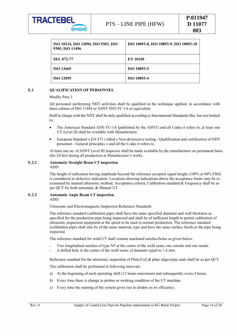
PTS – LINE PIPE (HFW) P.011947
D 11077
003
Rev. 0 Supply of Coated Line Pipe for Pipeline replacement in KG Basin Project Page 14 of 20
ISO 10124, ISO 12094, ISO 9303, ISO
9305, ISO 11496
ISO 10893-8, ISO 10893-9, ISO 10893-10
SEL 072-77 EN 10160
ISO 13665 ISO 10893-5
ISO 12095 ISO 10893-4
E.1 QUALIFICATION OF PERSONNEL
Modify Para 1:
All personnel performing NDT activities shall be qualified in the technique applied, in accordance with
latest edition of ISO 11484 or ASNT SNT-TC-1A or equivalent.
Staff in charge with the NDT shall be duly qualified according to International Standards like, but not limited
to:
The American Standard ASN-TC-1A (published by the ASNT) and all Codes it refers to, at least one
UT-Level III shall be available with Manufacturer.
European Standard « EN 473 » titled « Non-destructive testing - Qualification and certification of NDT
personnel - General principles » and all the Codes it refers to.
At least one no. of ASNT Level III inspector shall be made available by the manufacturer on permanent basis
(for 24 hrs) during all production at Manufacturer’s works.
E.2.1 Automatic Straight Beam UT inspection
ADD:
The height of indication having amplitude beyond the reference accepted signal height (100% at 80% FSH)
is considered as defective indication. Locations showing indications above the acceptance limits may be re-
examined by manual ultrasonic method. Acceptance criteria, Calibration standard & Frequency shall be as
per QCT for both automatic & Manual UT.
E.2.2 Automatic Angle Beam UT inspection
ADD:
Ultrasonic and Electromagnetic Inspection Reference Standards
The reference standard (calibration pipe) shall have the same specified diameter and wall thickness as
specified for the production pipe being inspected and shall be of sufficient length to permit calibration of
ultrasonic inspection equipment at the speed to be used in normal production. The reference standard
(calibration pipe) shall also be of the same material, type and have the same surface finish as the pipe being
inspected.
The reference standard for weld UT shall contain machined notches/holes as given below:
- Two longitudinal notches of type N5 at the centre of the weld seam, one outside and one inside.
- A drilled hole in the centre of the weld seam, of diameter equal to 1.6 mm.
Reference standard for the ultrasonic inspection of Plate/Coil & plate edges/pipe ends shall be as per QCT.
The calibration shall be performed at following intervals:
a) At the beginning of each operating shift (12 hours maximum) and subsequently every 4 hours.
b) Every time there is change in probes or working condition of the UT machine.
c) Every time the running of the system gives rise to doubts on its efficiency.

PTS – LINE PIPE (HFW) P.011947
D 11077
003
Rev. 0 Supply of Coated Line Pipe for Pipeline replacement in KG Basin Project Page 15 of 20
If during the above calibration verification, it is found that the equipment has not functioned satisfactorily in
the opinion of the Owner/Owner's Representative/TPIA, all the pipes or skelp already inspected after the
previous verification shall be inspected again at Manufacturer's cost.
E.3.1.4 Manual Ultrasonic Testing (MUT)
E.3.1.4.2 Modify:
Manual ultrasonic inspection of weld seams shall be in accordance with ISO 10893-11 as per API 5L Annex-
E Cl. nr. E2 (a).
Table E.11 (Modify)
Pipe Diameter D Wall Thickness t Probe Angle
< 610 mm (24 in) < 12.7 mm (0.500 in) 70° & 45°
E.3.1.4.5 ADD:
The weld at any pipe ends not covered by automatic ultrasonic equipment shall be inspected by manual
ultrasonic equipment with same sensitivity and capability as automatic equipment.
E.3.1.4.6 ADD:
Full circumference of both ends of each pipe shall be 100% manual ultrasonically tested over a circumferential
width of at least 100 mm with angular probes to detect cracks. In case of non-availability of angular probes
at the mill, the full circumference of both ends of each pipe shall be inspected with magnetic particle technique
over a circumferential width of at least 100 mm to detect surface cracks.
E.4. RADIOGRAPHIC INSPECTION OF WELD SEAMS
Not applicable for HFW pipes.
E.5. ULTRASONIC AND ELECTROMAGNETIC INSPECTION
Add:
Base Material Inspection - Ultrasonic testing shall be carried out for 100% area during manufacturing of
pipes.
E.5.4.3 Add:
General
Calibration of Testing Equipment
All equipment used for non-destructive inspection shall be checked for possible deviation towards its
calibrated value(s). The following check shall be performed:
at the start & end of every working shift or at the time of running if any doubt arises.
at every change-over of an equipment operator,
at the start and end of a production shift,
every time the running of the testing system is interrupted or when any doubt arises, Whichever occurs
first.
If on checks of the testing systems, the calibration requirements are not satisfied (even after increasing the
sensitivity for ultra-sonic equipment by 3db for allowance to system drift), then all pipes lengths tested after
the previous equipment check shall be retested after the testing system has been recalibrated.
E.7 Residual Magnetism
ADD:

PTS – LINE PIPE (HFW) P.011947
D 11077
003
Rev. 0 Supply of Coated Line Pipe for Pipeline replacement in KG Basin Project Page 16 of 20
The residual magnetic field created by ultrasonic or electromagnetic scanning device shall be released and
such residual magnanimity shall be inspected and accepted by TPIA and/ or Owner/ Owner’s Representative.
The average of the four readings shall not exceed 20 Gauss and no reading shall exceed 25 gauss when
measured with a hall-effect gauss meter, or equivalent values when measured with other type of instruments.
Annex G (normative) : PSL 2 pipe with resistance to ductile fracture propagation
Table G – Minimum CVN absorbed energy requirements
Specified
outside
diameter,
D
Mm (inch)
Full-size CVN average absorbed energy, Minimum
KvT a,b (J)
B to X42 > X42 to
X46
> X46 to
X52 > X52 to
X56 > X56 to
X60 > X60 to
X65 > X65 to
X70
457.0 (18) 40 40 40 40 40 45 50
508.0 (20) 40 40 40 40 42 47 53
610.0 (24) 40 40 40 41 46 51 58
711.0 (28) 40 40 40 45 49 56 62
813.0 (32) 40 40 42 48 53 59 66
914.0 (36) 40 40 45 51 56 63 70
1016.0 (40) 40 40 47 54 59 66 74
1118.0 (44) 40 42 50 56 62 70 78
1219.0 (48) 40 44 52 59 64 73 81
a The required KvL (longitudinal direction specimens) values shall be 50% higher than the required KvT
values for BM, weld and HAZ.
b Testing shall be performed at a temperature of 0 °C (32 °F) or at a lower temperature as specified in the
purchase order.
c For intermediate specified outside diameter, CVN average absorbed energy value (KvT) shall be same
value as given in the table for next higher specified outside diameter.
Annex J (normative) : PSL 2 pipe ordered for offshore service
Annex K (normative) : Non-destructive inspection for pipe ordered for sour service and/or
offshore service
Annex O (informative) : Use of the API Monogram by Licensees
Annex P (informative) : Equations for Threaded and Coupled Pipe and Background Equations
for Guided Bend and CVN Test Specimens
In Addition:
Annexure Q of GTS : ‘Purchaser Indicative Inspection and Quality Plan’, has been
replaced by Quality Control Table for Line Pipes (HFW) attached
with this specification. The same shall be applicable for HFW pipes.
Z-Z-Z

PTS – LINE PIPE (HFW) P.011947
D 11077
003
Rev. 0 Supply of Coated Line Pipe for Pipeline replacement in KG Basin Project Page 17 of 20
APPENDIX 1
TECHNICAL QUESTIONNAIRE FOR EVALUATION OF THE BIDS
1.0 Scope
Grade X70, Pipe ND – 18” – External (3LPE) & Internal (Epoxy) coated line Pipe as specified in MR.
Applicable Documents:
API 5L fourty-five Edition, December, 2012
Tractebel Specifications (PTS, GTS) & documents.
The information requested below shall be answered fully and wherever required necessary attachments
must be added. All information shall be relevant to the scope of the tender as stated above. No blank
space shall be left. If the part is not applicable, it should be written so.
2.0 General Information
2.1. Organization
Give a detailed description (organization structure, number of technical (job specific) people, facilities,
equipment, …..).
Concerning:
Overall Structure of the organization
…………………………………………………………………………………………
…………………………………………………………………………………………
Line Pipe production facilities and capacities:
…………………………………………………………………………………………
…………………………………………………………………………………………
Laboratories ( in-house or sub-contractor):
…………………………………………………………………………………………
…………………………………………………………………………………………
QA and/or QC department:
…………………………………………………………………………………………
…………………………………………………………………………………………
Non Destructive Testing department ( in-house or subcontractors )
…………………………………………………………………………………………
…………………………………………………………………………………………
R&D department ( In house or Research Institutes )
…………………………………………………………………………………………
…………………………………………………………………………………………
Other relevant departments or services ( In house or subcontractors )
…………………………………………………………………………………………
…………………………………………………………………………………………
2.2. Certificates and Approvals
Give type of approvals, date of issue and validity, for the scope of present tender
PTS – LINE PIPE (HFW) P.011947
D 11077
003
Rev. 0 Supply of Coated Line Pipe for Pipeline replacement in KG Basin Project Page 18 of 20
ISO certification ( ISO 9001 - 2015)
……………………………………………………………………………………….
……………………………………………………………………………………….
API approvals
………………………………………………………………………………………
………………………………………………………………………………………
Safety approvals
………………………………………………………………………………………
………………………………………………………………………………………
Third party approvals
………………………………………… …………………………………………..
……………………………………………………………………………………….
Client approvals
………………………………………… …………………………………………
………………………………………… …………………………………………
Other approvals
……………………………………………………………………………………
……………………………………………………………………………………
2.3. References for the manufacture/supply of API 5L X70 or above, Line pipe and coating separately for each
part
Give for the last five years
- Name of client or project (eventually name of contact person)
- Number of kilometers produced
- Inspection Agency (eventually name of contact person)
Year 2013 :
…………………………………………………………………………..
…………………………………………………………………………..
Year 2014 :
…………………………………………………………………………..
…………………………………………………………………………..
Year 2015:
…………………………………………………………………………..
…………………………………………………………………………..
Year 2016:
…………………………………………………………………………..
…………………………………………………………………………..
Year 2017 :
…………………………………………………………………………..
…………………………………………………………………………..
Year 2018 (eventually orders to be executed remainder of the year)
…………………………………………………………………………..

PTS – LINE PIPE (HFW) P.011947
D 11077
003
Rev. 0 Supply of Coated Line Pipe for Pipeline replacement in KG Basin Project Page 19 of 20
…………………………………………………………………………..
3.0 Fabrication and Inspection Procedures
3.1 Give a detailed description of the fabrication process utilized for these types of pipes
Forming (how many steps).
Body testing
Cold expansion or other intervention
Type of testing along the line
Maximum length of pipe that can be supplied for pipe sizes as per MR.
3.2 Give a detailed description of the production line(s), including type and location of the testing facilities.
Explain all relevant operations which you consider important for obtaining a high quality product.
3.3 Provide a relevant example (which will be applicable in case of an order) of a LOFC (List of fabrication and
control) as specified in ANNEX B of the GTS.
3.4 Provide a copy of all relevant NDT procedures (including acceptance criteria) that will be utilised in case of
an order, such as UT, RX, MT, PT, …….
3.5 Provide a list of the NDT personal, with their qualifications in each technique (Level 1, 2 or 3 according to
ASNT or other qualification authority) Specify if these operators are on your pay-roll or from a sub supplier.
3.6 Provide a copy of the applicable external coating procedures, including the preparation of the pipes before
coating.
3.7 Provide a copy of the applicable marking procedure.
3.8 Provide a list of all equipment used for the mechanical testing, chemical analysis (in house or subcontractors)
and tools for dimensional controls, including the date of calibration and the validity period of these
calibrations.
3.9 Provide your procedure concerning “Control of non-conforming products” and the procedure concerning
“Corrective and Preventive Actions” (See ISO 9001:2015).
4.0 Material Suppliers
4.1 Provide commitment letter from at least two possible plate/coils suppliers (from purchaser’s approved vendor
list).
4.2 Provide a procedure or any other document, which gives details concerning the characteristics of the material,
production controls, testing, certificates….required by you.
4.3 Provide a procedure or any other document, which gives details concerning the incoming testing and controls
of these materials, performed by your QA/QC department.
4.4 Provide your procedure concerning Supplier Evaluation (section 7.4 of ISO 9001:2015), detailing the controls
(audits?) performed on your suppliers. Also provide a copy of the planning of your supplier audits for last
three years.
5.0 Conformity with the requirements
Please confirm specifically that you will be confirming to the requirements stipulated in these tender
documents.
The issues in particular under consideration are:
Materials
- Chemical composition and analysis
- Mechanical properties and testing requirements

PTS – LINE PIPE (HFW) P.011947
D 11077
003
Rev. 0 Supply of Coated Line Pipe for Pipeline replacement in KG Basin Project Page 20 of 20
- Dimensions and tolerances
Hydrostatic Testing
Marking
Inspection
- Inspection procedure
- Personnel qualifications
External coating
Procedures and reports
The supplier must testify that all information given is correct and complete, and that they agree with an
eventual audit of these issues by purchaser, a designated auditing company and/or the appointed Inspection
Agency.
The reply to this questionnaire must be dated and validated by a company stamp, and signed by a responsible
person according to the rules of the companies Quality Management System.
All information given by the company will be treated by TRACTEBEL as confidential information and will
only be used for technical evaluation of the companies tender for the supply of line pipes for this Pipeline
project.
PTS – 3 LPE EXTERNAL
COATING
P.011947
D 11077
004
PIPELINE REPLACEMENT IN KG BASIN PROJECT
TRACTEBEL ENGINEERING PVT. LTD.
PARTICULAR TECHNICAL SPECIFICATION –
COATING -
3LAYER POLYETHYLENE EXTERNAL
RERT
DOC. NO. P.011947-D-11077-004
0 29.04.2019 Issued for Procurement Rajveer Panwar Nirjhar Chakrabarti SK Hussain
Rev. Date Description Prepared by Checked by Approved by
PTS – 3 LPE EXTERNAL
COATING
P.011947
D 11077
004
Rev. 0 Supply of Coated line Pipe for Pipeline replacement in KG Basin Project Page 1 of 1
TABLE OF CONTENTS
1.0 GENERAL .............................................................................................................................. 1
2.0 SCOPE ................................................................................................................................... 1
3.0 REFERENCE DOCUMENTS ..................................................................................................... 1
4.0 MATERIALS .......................................................................................................................... 3
5.0 FUNCTIONAL REQUIREMENTS AND PROPERTIES OF COATING .......................................... 5
6.0 MEASUREMENT AND LOGGING ............................................................................................ 7
7.0 COATING PROCEDURE AND QUALIFICATION ...................................................................... 7
8.0 PIPE SURFACE PREPARATION ........................................................................................... 12
9.0 COATING APPLICATION ..................................................................................................... 15
10.0 INSPECTION AND TESTING ............................................................................................... 17
11.0 HANDLING, TRANSPORTATION AND STORAGE ................................................................. 21
12.0 REPAIR OF COATING.......................................................................................................... 22
13.0 MARKING ........................................................................................................................... 23
14.0 QUALITY ASSURANCE ........................................................................................................ 23

PTS – 3 LPE EXTERNAL
COATING
P.011947
D 11077
004
Rev. 0 Supply of Coated Line Pipe for Pipeline replacement in KG Basin Project Page 1 of 25
1.0 GENERAL
The present document covers the technical specification for coating of line pipes as follows:
Table-1 : PIPELINE COATING REQUIREMENT
Sl
No
Line size
(inch) Type of pipes
Thickness
of Line
Pipe
Approx.
Length in
Meters
External
Coating
Internal
Coating
1 18” SAWL / SAWH /
HFW 11.1 8000 √ √
2 18” SAWL / SAWH /
HFW 12.7 7500 √ √
3 18” SAWL 14.3 780 NIL NIL
Pipe length shall be between 11.5 to 12.5 m. Thickness wise average length of pipes supplied shall not be less
than 12.0 m. For sampling pipes, minimum length of 11.0 m is acceptable.
The average length shall be cumulative as measured at Pipe Mill despatch.
Pipe traceability and die stamping: The pipe mill will ensure that all the documents pertaining to traceability
of pipe are handed over to coating section along with soft copy of packing list and history sheet indicating
pipe no., heat no., acceptance no. and length of pipe, which will further be completed by the coating section
in continuation.
The accepted pipe will have pipe no. on both face of the square/bevel ends along with TPIA stamp which will
be preserved by the coating contractor upto the last stage till the pipes are handed over to the designated store
of GAIL.
The present document covers the technical specification for coating of line pipes.
The following sections cover the guidelines for:- External Coating
2.0 SCOPE
This specification covers the minimum requirements for supply/arrangement of all materials, plant,
equipment, plant sites, consumables, utilities and application including all labour, supervision, inspection and
tests, transportation, handling, coating integrity etc. for application of external anti-corrosion coating of pipes
by using 3 Layer Side Extruded Polyethylene coating conforming to ISO 21809-1 ‘Petroleum and Natural
Gas Industries-External Coatings for buried and submerged pipeline transportation systems-Part 1:Polyolefin
Coatings’, and the Internal epoxy coating conforming to ISO 15741 “Friction reduction coatings for the
interior of on and off shore steel pipe lines for non corrosive gases”.
3.0 REFERENCE DOCUMENTS
Reference has also been made to the latest edition (edition enforce at the time of issue of enquiry) of the
following standards, codes and specifications. The edition enforce at the time of floating the enquiry shall be
termed as latest edition.
i. ISO 21809-1 : Petroleum and Natural Gas Industries-External Coatings for buried and
submerged pipeline transportation systems-Part 1:Polyolefin Coatings
ii. DIN EN 30670 : Polyethylene Coating on Steel Pipes & Fittings – Requirement and Testing
iii. ISO 21809-2 : Petroleum and Natural Gas Industries-External Coatings for buried and
submerged pipeline transportation systems-Part 2: Fusion-bonded epoxy
coatings.

PTS – 3 LPE EXTERNAL
COATING
P.011947
D 11077
004
Rev. 0 Supply of Coated Line Pipe for Pipeline replacement in KG Basin Project Page 2 of 25
iv. ISO 15741 : Friction reduction coatings for the interior of on and off shore steel
pipelines for non-corrosive gases.
v. ASTM D-149 : Standard Test Methods of Dielectric Breakdown Voltage and Dielectric
Strength of Solid Electrical Insulating Materials at Commercial
Frequencies.
vi. ASTM D-257 : Standard Test Methods for D-C Resistance or Conductance of Insulating
Materials.
vii. ASTM D-792 : Standard Test Method for Density and Specific Gravity (Relative Density)
of Plastics by Displacement.
viii. ASTM D-1238 : Test Method for Flow Rates of Thermoplastics by Extrusion.
ix. ASTM D-1603 : Test Method for Carbon Black in Olefin Plastics.
x. ASTM D-1693 : Test Method for Environmental Stress Cracking of Ethylene Plastics
xi. API RP 5L1 : Recommended Practice for Railroad Transportation of Line pipe.
xii. API RP 5LW : Transportation of Line Pipe on Barges and Marine Vessels.
xiii. API RP 5LT : Recommended Practice for Truck Transportation of Line Pipe.
xiv. BS EN 10204 : Metallic Products – Types of Inspection Documents.
xv. DIN 53735 : Testing of Plastics: Determination of Melt Index of Thermoplastics.
xvi. ISO 8501-1 : Preparation of Steel Substrates before Application of Paints and Related
Products – Visual Assessment of Surface Cleanliness: Part 1-
Representative Photographs of the Change of Appearance imparted to Steel
when Blast Cleaned with different Abrasives.
xvii. ISO 8502 – 3 : Preparation of Steel Substrates before Application of Paints and Related
Products – Part 3 – Assessment of Dust on Steel Surfaces Prepared for
Painting (Pressure Sensitive Tape Method).
xviii. ISO 9002 : Quality Systems: Model for Quality Assurance in Production, Installation
and Servicing.
xix. ISO 306 : Plastics-Thermoplastic materials-- Determination of Vicat softening
temperature.
xx. ISO 15512 : Plastics - Determination of water content.
xxi. ISO 527-2 : Determination of tensile properties -- Part 2: Test conditions for moulding
and extrusion plastics
xxii. ISO 527-3 : 3 Plastics - Determination of tensile properties - Part 3: Test conditions for
films and sheets.
xxiii. ISO 868 : Plastics and ebonite -- Determination of indentation hardness by means of
a durometer (Shore hardness).
xxiv. ISO 11357 : Plastics - Differential scanning calorimetry (DSC) - Part 7: Determination
of crystallization kinetics.
xxv. ISO 11124 : Preparation of Steel Substrates Before Application of Paints and Related
Products.
xxvi. ISO 1133 : Plastics –Determination of Melt mass- flow rate (MFR) and melt volume –
flow rate (MVR) of thermoplastics.
xxvii. API 5L : Specification for Line Pipe
xxviii. ASME B31.8 : Gas Transmission and Distribution Piping Systems.
xxix. ASME B31.4 : Liquid Transportation Systems for Hydrocarbons, Liquid Petroleum Gas,
Anhydrous Ammonia, and Alcohols

PTS – 3 LPE EXTERNAL
COATING
P.011947
D 11077
004
Rev. 0 Supply of Coated Line Pipe for Pipeline replacement in KG Basin Project Page 3 of 25
The Contractor shall be familiar with the requirements of these documents and shall make them readily
available at the coating plant to all persons concerned with carrying out the works specified in this
specification.
3.1 Terms And Definitions
GTS means “ General Technical Specification 740/GTS/404 Rev.0 ” and all
documents it refers to.
PTS means the present “ Particular Technical Specification P.011947 D
11077 004” and all its appendices, if any.
OWNER Shall mean “GAIL (INDIA) LIMITED.”, being the Purchaser of Line
Pipes
CONSULTANT /
OWNER
REPRESENTATIVE
Shall means “ TRACTEBEL Engineering Pvt. Limited ” / The
company nominated by the owner to design the natural gas transport or
distribution system and to specify the equipment
TPIA means the Third Party Inspection Agency
MANUFACTURER means the Manufacturer of the pipes as well as its sub-contractor(s).
4.0 MATERIALS
4.1 The three layer coating system shall comprise of a powder epoxy primer, polymeric adhesive and a medium
density polyethylene topcoat. Coating materials shall be suitable for the service conditions and the pipe sizes
involved. The coating materials i.e. epoxy powder; adhesive and polyethylene compound shall have proven
compatibility. The coating system and materials shall be pre-qualified and approved by Owner in accordance
with provisions of Annexure I of this specification. Contractor shall obtain prior approval from Owner for the
coating system and coating materials.
4.2 The coating materials Manufacturer shall carry out tests for all properties specified in Para 5.3.1 and 5.3.2 for
each batch of epoxy, adhesive and polyethylene compound. In addition, the Manufacturer shall also furnish
Infra-red Scan for each batch of epoxy powder. The coating materials Manufacturer shall issue test certificates
as per BS EN 10204, 3.1 for each batch of materials supplied to Contractor indicating all contents/ parameters
required for batch certification as per clause 8.3 of ISO-21809-1 and the same shall be submitted to Owner
for approval prior to their use.
4.3 In addition to Manufacturer’s certificate, the Contractor shall draw samples from each batch of epoxy,
adhesive and polyethylene in the presence of Owner Representative and test for the following properties at
the coating yard at least one week prior to its use, to establish compliance with the Manufacturer’s test
certificates.
a. Epoxy Powder:
i. Density
ii. Gel Time
iii. Cure time
iv. Moisture content
v. Thermal Characteristics (Tg1, Tg2, H)
vi. Particle Size or Sieve Analysis
vii. Infrared Scan
b. Adhesive:
i. Specific Gravity
ii. Melt Flow Rate
PTS – 3 LPE EXTERNAL
COATING
P.011947
D 11077
004
Rev. 0 Supply of Coated Line Pipe for Pipeline replacement in KG Basin Project Page 4 of 25
iii. Vicat Softening Point
iv. Moisture content
c. Polyethylene:
i. Melt Flow Rate
ii. Specific Gravity
iii. Vicat Softening Point
iv. Moisture Content
v. Oxidative Induction Time
vi. Tensile Strength
vii. Hardness
viii. Volume Resistivity
ix. Di-electric Withstand
x. Elongation
xi. Environmental Stress, Crack Resistance, High Density, Conditioning
xii. Carbon Black Content
In case of failure of any of the above tests in a batch, that batch of material shall be tested for all other tests
required as per Para 5.3.1 and 5.3.2 including the tests which failed. If all tests pass, the batch shall be accepted
for coating. If any of the tests fail, entire batch of material shall be rejected and shall not be used for the
coating.
4.4 All materials to be used shall be supplied in sealed, damage free containers and shall be suitably marked with
the following minimum information:
a. Name of the Manufacturer
b. Manufacturing standard
c. Health, safety and environmental Instructions
d. Receiving inspection acceptance criteria
e. Data Sheets
f. Storage instruction.
g. Type of Material
h. Batch Number
i. Place and Date of Manufacture
j. Shelf Life/Expiry Date (if applicable)
k. Quantity
l. Instruction of application procedure with key parameters
All materials noted to be without above identification shall be deemed suspect and shall be rejected by Owner.
Such materials shall not be used for coating and shall be removed from site and replaced by Contractor at his
expense.
4.5 Contractor shall ensure that all coating materials are properly stored in accordance with the Manufacturer’s
recommendation at all times, to prevent damage and deterioration in quality prior to use.
4.6 Contractor shall be required to use all materials on a date received rotation basis, i.e. first in - first used basis.
PTS – 3 LPE EXTERNAL
COATING
P.011947
D 11077
004
Rev. 0 Supply of Coated Line Pipe for Pipeline replacement in KG Basin Project Page 5 of 25
5.0 FUNCTIONAL REQUIREMENTS AND PROPERTIES OF COATING
5.1 The coating shall be able to withstand a design temperature of +80˚ C (Tmax.) and in service operating
temperature of 65°C and shall conform to ‘Class B as per ISO 21809-1.
5.2 The topcoat polyethylene used shall be a black readymade compound, fully stabilized against influence of
ultraviolet radiation (i.e. sunlight), oxygen in air and heat (due to environmental temperature as specified
above). No appreciable changes shall occur during exposure to such environments up to at least a period of
6000 hours. The Contractor shall submit guarantee certificate from Manufacturer in this regard.
5.3 Properties
Properties of coating system and coating material shall comply the requirements indicated in subsequent
paragraphs. In case the coating / material properties are tested as per test methods/standards other than
specified herein below, the same may be accepted provided the test procedures and test conditions are same
or more stringent than the specified.
5.3.1 Properties of Epoxy Powder and Adhesive
Contractor shall choose brand of epoxy powder and adhesive as per approved Contractor list that will achieve
the functional requirements and properties of coating system as specified in clause no. 5.1 and 5.3.3 of this
specification respectively.
5.3.1.1 Epoxy powder properties shall meet the properties listed below
Sl. No. Properties Unit Requirement Test Method
a. Moisture Content % mass ≤ 0.5 ISO 21809 – 1
Annexure K
b. Minimum glass transition
temperature (Tg2) ˚C
≥ 95 and within
manufacturer’s specification
ISO 21809 – 1
Annexure D
c. Gel time at 205˚C ± 3˚C s
Within 20% of the nominal
value specified by the
manufacturer
ISO 21809 – 1
Annexure J
d. Density g/cm3
Within ± 0.05 of the
manufacturer’s specified
nominal value
ISO 21809 – 1
Annexure N
The colour of epoxy powder shall be either green or dark red or any other colour approved by Owner except
grey colour.
5.3.1.2 Copolymer grafted adhesive shall have the following properties:
Sl. No. Properties Unit Requirement Test Method
a. Melt flow rate (190˚C / 2.16 Kg) g/10 minutes ≥1.0 ASTM D 1238
b. Vicat softening point ˚C ≥ 100 ISO 306
c. Specific Gravity - ≥ 0.930 ASTM D 792
d. Elongation at break at 23˚C % ≥ 600 ISO 527 – 2
e. Tensile yield strength at 23˚C MPa ≥ 8 ISO 527 – 2
f. Water content % ≤ 0.1 ISO 15512
5.3.2 Properties of Polyethylene Compound
Sl. No. Properties Unit Requirement Test Method

PTS – 3 LPE EXTERNAL
COATING
P.011947
D 11077
004
Rev. 0 Supply of Coated Line Pipe for Pipeline replacement in KG Basin Project Page 6 of 25
a. Tensile strength at 23˚C N/mm2 ≥ 17 ISO 527 – 2 or
ISO 527 – 3
b. Melt flow rate (190˚C / 2.16 Kg) g/10 minutes ≥ 0.25 ASTM D 1238
c. Density at 23˚C g/cm3 ≥ 0.940 (HDPE) ISO 1183
d. Hardness at 23˚C Shore D ≥ 55 (MDPE)
≥ 60 (HDPE) ISO 868
e. Water absorption, 24 hours at 23˚C % ≤ 0.05 ASTM D 570 or
ISO 15512
f. Volume Resistivity at 23˚C Ohm – cm ≥ 1016 ASTM D 257
g. Dielectric withstand, 1000 Volt / sec
rise at 23˚C Volts / mm ≥ 30,000 ASTM D 149
h. Softening point ˚C ≥ 110 ISO 306
i. Elongation at break at 23˚C % ≥ 600
ASTM D 638
ISO 527 – 2 OR
ISO 527 – 3
j. Oxidative induction time in oxygen
at 220C, Aluminium pan, no screen Minutes 10 ISO 11357
k.
Environmental Stress Crack
Resistance (ESCR) (for F50)
Medium Density [Condition
“C”]
High Density [Condition “B”]
Hours
300
300
ASTM D 1693
l. Carbon Black Content % ≥ 2 ASTM D 1603
m. UV resistance and thermal ageing % ΔMFR ≤ 35 ISO 21809 – 1
Annexure G
5.3.3 Properties of Applied Coating System
Sl. No. Properties Unit Requirement Test Method
a.
Bond Strength (Peel Strength)
@ 23°C +/- 3°C
@ Tmax. (80 °C) +/- 3°C
N / mm
≥ 15
≥ 3
ISO 21809-1
Annexure C
C.3.2 & 3.3
b.
Impact Strength
(Min. of 30 impacts on body along
the length. No breakdown allowed
when tested at 25 KV)
Joules per mm
of coating
thickness
≥ 7 ISO 21809-1
Annexure E
c.
Indentation Hardness
@ 23 +/- 2°C
@ 80 +/- 2°C
mm
≤ 0.2
≤ 0.3
ISO 21809-1
Annexure F
d. Elongation at Failure % ≥ 400 ISO 527 – 3
e. Coating Resistivity Ohm – m2 108 min. DIN 30670
f. Cathodic Disbondment mm ISO 21809-1
PTS – 3 LPE EXTERNAL
COATING
P.011947
D 11077
004
Rev. 0 Supply of Coated Line Pipe for Pipeline replacement in KG Basin Project Page 7 of 25
23 +/- 3°C for 28d - 1.5V
65 +/- 3°C for 24h - 3.5V
Tmax. (80 °C) +/- 3°C for 28d -
1.5V
Average radius
of Cathodic
disbondment
≤ 7
≤ 7
≤ 15
Annexure H
g.
Degree of Cure of Epoxy
Percentage Cure, H
ΔTg
%
°C
95
≤ 5
ISO 21809-1
Annexure D
h. Hot Water Immersion test mm
Average ≤ 2
And maximum
≤ 3
ISO 21809-1
Annexure M
i. Flexibility
No cracking at
an angle of 2.0 °
per pipe
ISO 21809-1
Annexure I
5.4 The acceptable combinations of coating material shall be as per Annexure-I.
6.0 MEASUREMENT AND LOGGING
The scope of the Contractor includes maintaining records containing all the relevant data of individual pipe
and pipe coating including pipe number, heat number, diameter, length, wall thickness, defects, coating
number, batches of materials, sampling, testing, damages, repairs, rejects and any other information that
Owner considers to be relevant and required for all incoming bare pipes and Owner approved outgoing coated
pipes as applicable. The records shall be maintained in MS excel for proper tracking and filter properties
Contractor’s documentation shall be designed to ensure full traceability of pipe and coating materials through
all stages of coating and testing. Contractor shall submit this information in the form of a report at the agreed
intervals.
7.0 COATING PROCEDURE AND QUALIFICATION
7.1 Upon award of the CONTRACT, the Contractor shall submit within two (2) weeks, for Owner approval, a
detailed report including the below, but not limited to, the following:
a. Details of plant(s), location(s), layout, capacity and production rate(s).
b. Details of the equipment available to carry out the coating works including surface preparation, surface
pretreatment comprising of de-ionized water wash, phosphoric acid wash and chromate treatment , epoxy
powder application and its recycling system, adhesive & polyethylene extrusion, moisture control
facilities available for coating materials.
c. Details of process control and inspection equipment required for the coating process such as surface
preparation, surface pretreatment, temperature control during epoxy spray, thickness control, holiday
testers, etc.
d. Facilities in the yard for unloading, handling, transport, production, storage, stockpiling, loading of bare
and coated pipes and warehouses for storage of other coating materials.
e. Plant Organization Chart and availability of manpower including coating specialist
f. Details of utilities/facilities such as water, power, fuel, access roads and communication etc.
After Owner has given approval; no change in plant set-up shall be made. However, unavoidable changes
shall be executed only after obtaining written approval from Owner.
7.2 At least two (2) weeks prior to the commencement of production coating, a detailed procedure of the
Contractor's methods, material proposed, etc., shall be formulated by the Contractor and submitted for Owner
approval in the form of a bound manual. The procedure shall include, but not limited to, the following
information and proposals:
a. Pipe inspection at the time of bare pipe receipt.

PTS – 3 LPE EXTERNAL
COATING
P.011947
D 11077
004
Rev. 0 Supply of Coated Line Pipe for Pipeline replacement in KG Basin Project Page 8 of 25
b. Steel surface preparation, including preheating, removal of steel defects, method of pipe cleaning, dust
removal, abrasive blast cleaning and surface profile; methods of measurements and consumables.
c. Pipe heating, temperatures and control prior to epoxy application.
d. Complete details of raw materials including current data sheets showing values for all the properties
specified together with quality control and application procedure recommendations from
manufacturer(s).
e. Application of FBE powder, adhesive and polyethylene, including characteristics, temperature, line
speed, application window, curing time, etc.
f. Quenching and cooling, including time and temperature.
g. Quality Assurance System, Quality Plan, Inspection and Test Plan and reporting formats, including
instrument and equipment types, makes and uses, etc
h. Detailed method of repair of coating defects duly classified depending upon nature and magnitude of
defects and repair thereof including coating stripping technique
i. Details of instrument and equipment calibration methods including relevant standards and examples of
calibration certificates.
j. Complete details and inventory of laboratory and equipment for procedure qualification and regular
production
k. Pipe handling and stock piling procedures including pipe tracking, traceability, pipe end protection and
protection against adverse ambient conditions during storage.
l. Sample of recording and reporting formats, including laboratory reports, certificates and requirement as
per clause 6.0 of this specification.
m. Complete details of test certificates for raw materials including test methods and standards used.
n. Test certificates from PE compound manufacturer for tests for thermal aging, coating resistivity and aging
under exposure to light. These test certificates shall not be older than three years.
o. Health, Safety and Environment Plans.
p. Storage details of coating materials and chemicals.
q. Continuous temperature monitoring at various stages of coating Procedure Qualification Tests (PQT)
shall be carried out only after obtaining written approval of the above procedure from Owner. No change
in the procedure shall be made after the Owner has given approval. However, unavoidable changes shall
be executed only after obtaining written approval from Owner.
7.3 Prior to start of production, the Contractor shall, at his expense, carry out a coating PQT for each pipe diameter
on max. wall thickness, for each type of pipe, for each coating material combination and for each plant, to
prove that his plant, materials, and coating procedures result in a quality of end product conforming to the
properties stated in clause 5.3, relevant standards, specifications and material manufacturer's
recommendations. Contractor shall give seven (7) working day’s notice to witness all procedures and tests.
A batch representing a normal production run, typically 15 pipes, shall be coated in accordance with the
approved coating procedure and the coating operations witnessed by Owner Representative. Out of these
pipes, at least one pipe at start & end of PQT shall be coated partly with epoxy and partly with both epoxy
and adhesive layers.
At least 10 (ten) test pipes shall be selected by Owner Representative for coating procedure approval tests
and shall be subjected to procedure qualification testing as described hereinafter. Owner Representative shall
witness all tests. Out of 10 (ten) test pipes, 2 (two) pipe partly coated with epoxy and partly coated with both
epoxy and adhesive layers shall be included. Remaining 8 (eight) test pipes shall have all three layers.
During PQT, the Contractor shall qualify various procedures forming a part of coating operations as detailed
subsequently.
7.4 Qualification of Procedures
7.4.1 Epoxy Powder Application & Recycling
PTS – 3 LPE EXTERNAL
COATING
P.011947
D 11077
004
Rev. 0 Supply of Coated Line Pipe for Pipeline replacement in KG Basin Project Page 9 of 25
During pre-qualification, air pressure in the epoxy spray guns, satisfactory functioning of monitoring system,
line speed v/s coating thickness, etc. shall be established. Dew point of air used to supply the fluidized bed,
epoxy spray system and epoxy recycling system shall be recorded during the PQT.
Also, the Contractor shall remove samples of reclaimed powder from the reclamation system. These samples
of reclaimed powder shall be subject to a detailed visual examination, thermal analysis and moisture content
tests. The properties of the reclaimed powder shall be within the range specified by the Manufacturer of epoxy
powder. In case the properties of the reclaimed powder are out of the range specified by the Manufacturer,
Contractor shall not the use the reclaimed powder during the regular production.
7.4.2 Pipe Pre-heating
The Contractor shall establish the temperature variation due to in-coming pipe temperature, line speed
variation, wall thickness variation, emissivity, interruptions, etc. and document the same during the PQT
stage. During PQT, proper functioning of pipe temperature monitoring and recording system including
alarm/hooter shall be demonstrated to the Owner Representative.
7.4.3 Surface Preparation
The procedure to clean and prepare the pipe surface shall be in accordance with the requirements of this
specification. The ratio of shot to grit shall be established during procedure qualification testing, such that the
resultant surface profile is not dished and rounded. The qualification shall be performed through a visual
inspection, measurement of roughness and check of the presence of dust on the abrasive blast cleaned pipe
surface.
7.4.4 Chemical Pre-treatment
7.4.4.1 Phosphoric Acid Wash followed by De-ionised Water Wash
The procedure to apply the chemical pre-treatment viz. phosphoric acid wash followed by de-ionised water
wash shall result in intended cleaning requirements of this specification. Working solution preparation,
maintaining concentration, application procedure including method of spreading, spreading rate, drying times,
etc. depending upon the cleanliness/temperature of the incoming pipe and the line speed shall be established.
Temperature of the chemical, pipe pre-heat temperature vs line speed vs dwell time, rinsing procedure, testing
& control, rectificatory measures, drying procedure etc. shall be clearly established during PQT. Also the
quality of the de-ionised water shall be established during PQT.
7.4.4.2 Chromate Treatment
The procedure to apply the chromate treatment shall result in intended cleaning requirements of this
specification. Working solution preparation, maintaining concentration, application procedure including
method of spreading, spreading rate, drying times, etc. depending upon the temperature of the incoming pipe
and the line speed shall be established. Temperature of the chemical, pipe pre-heat temperature vs. line speed,
pipe heating after chromating and time limit within which the pipe to be heated, testing & control, rectificatory
measures, shall be clearly established during PQT.
7.4.5 Coating Application
The Owner Representative will check the correctness of each coating application operation, values of the
main parameters of each operation, pre-heating pipe surface temperature prior to epoxy powder application
temperature, line speed, fusion bonded epoxy curing time, temperature and flow rate of co-polymer adhesive
and polyethylene, etc. and the same shall be recorded. These values shall be complied with during regular
production.
7.5 Qualification of Applied Coating
7.5.1 Tests on pipe coated partly with epoxy and partly with epoxy & adhesive layers
a. Degree of Cure
Epoxy film samples (minimum 4 no.) shall be scrapped from the coated pipe and the samples shall be
taken for cure test using Differential Scanning Calorimetry (DSC) procedure mentioned in clause A8 of
ISO 21809-2 Fusion bonded epoxy coating. Care shall be taken to remove the samples of full film
thickness avoiding inclusion of steel debris. Glass transition temperature differential (Tg) and % cure (H)
shall comply with the specified requirements.

PTS – 3 LPE EXTERNAL
COATING
P.011947
D 11077
004
Rev. 0 Supply of Coated Line Pipe for Pipeline replacement in KG Basin Project Page 10 of 25
b. Epoxy Layer Thickness
Epoxy layer thickness shall be checked at every one meter spacing at 3, 6, 9 and 12 o’clock positions.
The thickness shall comply with the specified thickness requirements.
c. Adhesive layer Thickness
Adhesive layer thickness shall be checked at every one meter spacing at 3, 6, 9 and 12 o’clock positions.
The thickness shall comply with the specified thickness requirements.
d. Holiday Inspection
Entire pipe shall be subject to holiday inspection and the test voltage shall be set to exceed 5 v/micron of
epoxy thickness specified for the portion coated only with epoxy layer.
e. Dry Adhesion
Dry adhesion test shall be carried out as per clause A.4 of ISO 21809-2 Fusion bonded epoxy coating.
The rating obtain shall be either 1 or 2.
f. 24 Hrs Adhesion Test.
Adhesion Test (24 hrs) shall be carried out on the epoxy coated pipe as per clause A.15 of ISO 21809-2
Fusion bonded epoxy coating. The rating obtained shall be from 1 to 3.
g. Flexibility test
2° flexibility test shall be carried out as per annexure A.12 of ISO 21809-2 Fusion bonded epoxy coating.
No cracking should be observed.
h. Porosity Test
Cross section porosity and interface porosity tests shall be carried out on the epoxy coated pipe. Test
method and acceptance criteria shall comply as per clause A.11 of ISO 21809-2 Fusion bonded epoxy
coating
7.5.2 Tests on pipes coated with all three layers
a) Bond Strength (Peel Test):
Five test pipes shall be selected for bond strength tests. On each of the selected pipes, three peel tests
shall be performed for each specified temperature i.e. one at each end and one in the middle of the pipe
and specified requirements shall be complied with, i.e. bond strength as well as mode of separation.
Length of peel shall be minimum 65 mm. None of these samples shall fail.
b) Impact Strength:
Three test pipes shall be selected for impact strength test and the test shall meet the specified
requirements.
c) Indentation Hardness:
Two samples for both temperatures from all pipes shall be taken. If any one of these samples fails to
satisfy the specified requirements, then the test shall be repeated on four more samples. In this case, none
of the samples shall fail.
d) Elongation at failure:
Six samples each from three coated pipes i.e. 18 samples in all shall be tested and the test shall comply
the specified requirement. Only one sample per pipe may fail.
e) Cathodic Disbondment Test:
Three CD tests shall be carried out for the total lot of test pipes having all three layers.
During PQT:
i. One test sample shall be carried out for 28 days at 23 ±3 °C.
ii. One test sample shall be carried out 24 hrs, at 65 ±3 °C.
PTS – 3 LPE EXTERNAL
COATING
P.011947
D 11077
004
Rev. 0 Supply of Coated Line Pipe for Pipeline replacement in KG Basin Project Page 11 of 25
iii. One test sample shall be carried out 28 days, at Tmax (80) ±3 °C.
Regular production:
i. One test sample per 2 week or once per every batch of epoxy powder whichever is more
frequent shall be carried out for 24 hrs, at 65 ±3 °C to be performed.
f) Holiday Inspection
All the pipes shall be subject to holiday inspection. The test voltage shall be as specified in Para 10.2.3(b).
The pipes shall pass the test at 25 kV.
g) Coating Thickness Measurement
All pipes shall be subject to coating thickness measurements. Acceptance criteria shall be as per Para
10.2.2.
h) Air Entrapment
One sample each from pipe body and on weld (if applicable) shall be taken from all four coated pipes
and the specified requirements shall be complied with.
i) Degree of Cure
Epoxy film samples (minimum 4 no., equally spaced) shall be scrapped from one coated pipe and the
samples shall be taken for cure test using Differential Scanning Calorimetry (DSC) procedure. Silicon
coated sulphite paper shall be placed between the epoxy layer and adhesive layer immediately after epoxy
application, to ensure physical separation of epoxy & adhesive as well as to prevent contamination of
epoxy with adhesive layer, at a location from where the epoxy samples are to be removed for the test.
Care shall be taken to remove the samples of full film thickness avoiding inclusion of steel debris. Glass
transition temperature differential (Tg) and % cure (H) shall comply with the specified requirements.
j) Hot Water Immersion :
One test pipe shall be selected for hot water immersion test. The test method and acceptance criteria shall
be as per annexure M of ISO 21809 Part 1- Polyolefin Coatings.
k) Flexibility:
One test pipe shall be selected for Flexibility test. The test method and acceptance criteria shall be as per
annexure I of ISO 21809 Part 1- Polyolefin Coatings.
l) Coating Resistance test
The contractor at the start of production shall prepare a sample and perform the test as per
DIN30670:2012 and submit the report to the customer.
7.5.3 Inspection of all test pipes
All pipes shall be subject to the following inspections:
a) Surface cleanliness, surface roughness measurements and dust control immediately after second abrasive
blast cleaning and salt test.
b) Visual inspection of finished coating, cut back dimension, internal/external cleanliness, end sealing and
bevel inspection.
Acceptance criteria for all inspection and testing shall be as specified in clause no. 5.3.3
7.6 After completion of the qualification tests and inspection as per para 7.4 and 7.5 above, the Contractor shall
prepare and issue to Owner for approval a detailed report of the above tests and inspection including test
reports/certificates of all materials and coatings tested. Only upon written approval from Owner, Contractor
shall commence production coating.
7.7 On successful completion of PQT, coating of all test pipes shall be removed and completely recycled as per
the approved coating procedure specification, at Contractor’s expense. Remaining pipes will be accepted by
Owner provided they meet the requirements of this specification and need not be stripped and re-cycled.

PTS – 3 LPE EXTERNAL
COATING
P.011947
D 11077
004
Rev. 0 Supply of Coated Line Pipe for Pipeline replacement in KG Basin Project Page 12 of 25
7.8 The Contractor shall re-establish the requirements of qualification and in a manner as stated before or to the
extent considered necessary by Owner, in the event of, but not limited to, the following:
- Every time there is a change in the previously qualified procedure.
- Every time there is a change in the manufacturer and change in formulation of any of the raw materials
and change in location of raw material manufacture.
- Every time the coating yard is shifted from one location to the other or every time the critical coating
equipments (induction heater, epoxy spray system, extruder, etc) are shifted.
- Any change in line speed during coating application.
- Any time when in Owner’s opinion the properties are deemed to be suspect during regular production
tests.
7.9 Owner reserves the right to conduct any or all the test required for qualification through an independent
laboratory or agency at the cost of Contractor when in Owner’s opinion, the results are deemed suspect.
Owner’s decision shall be final.
8.0 PIPE SURFACE PREPARATION
8.1 Unless specified otherwise, the pipes shall be supplied free from mill applied oils but may be subject to
contamination occurring during transit.
8.2 Prior to cleaning operation, Contractor shall visually examine the pipes and shall ensure that all defects, flats
and other damages have been repaired or removed. The Contractor shall also remove marking stickers, if any,
present within the pipe. Record shall be kept of such marking on the stickers to ensure traceability of pipe
after coating.
8.3 Any oil, grease, salt or other contaminants detrimental to the formation of a good coating bond or coating
quality shall be removed prior to coating application. Contaminants may be removed by the use of non-oily
solvents. Gasoline or kerosene shall not be used for this purpose. Visible oil and grease spots shall be removed
by solvent wiping. Solvent cleaning shall be in accordance with SSPC-SP1. Steel surface shall be allowed to
dry before abrasive cleaning.
8.4 All pipes shall be preheated to a temperature of 65°C to 85°C prior to abrasive blast cleaning. The external
surface of the pipe shall be cleaned using 2 no. dry abrasive blast cleaning units to achieve the specified
surface cleanliness and profile. After first abrasive blast cleaning, chemical pre-treatment with phosphoric
acid solution as per clause no. 8.6 shall be carried out prior to second abrasive blast cleaning. However, at the
option of Contractor, chemical pre-treatment with phosphoric acid solution as per clause no. 8.6 may be
carried out after the second abrasive blaster.
The abrasive blast cleaning units shall have an effective dust collection system to ensure total removal of dust
generated during blast cleaning from the pipe surface. The equipment used for abrasive blast cleaning shall
meet the specified requirements and shall be free from oil, water soluble salts and other forms of
contamination to ensure that the cleaning process is not impaired. Traps, separators and filters shall be
checked for condensed water and oil at the start of each shift and emptied and cleaned regularly. During
abrasive blast cleaning, the metallic abrasive shall be continuously sieved to remove “fines” and
“contaminants” and the quality checked at every four hours. Abrasives used for blast cleaning shall comply
ISO-11124.
8.5 Suitable plugs shall be provided at both pipe ends to prevent entry of any shot/grit into the pipe during blast
cleaning operations. These plugs shall be removed after blast cleaning. Alternatively the Contractor may link
the pipes suitably together to prevent the entry of any short/grit into the pipe.
8.6 Chemical Pre-treatment with Phosphoric Acid Solution
8.6.1 All pipes shall be provided chemical pre-treatment with phosphoric acid solution. 10% (+2%) solution of
phosphoric acid, Oakite 31 / 33 or equivalent, shall be used to remove all soluble salts and other soluble
contaminants.
8.6.2 The Contractor shall provide data sheets and supporting documentation for the phosphoric acid to be used.
The documentation shall verify that the phosphoric acid is suitable for the treatment of line pipe prior to the
PTS – 3 LPE EXTERNAL
COATING
P.011947
D 11077
004
Rev. 0 Supply of Coated Line Pipe for Pipeline replacement in KG Basin Project Page 13 of 25
application of the specific fusion bonded epoxy powder being applied and the final coating will meet fully
the requirements of this specification.
8.6.3 The pipe temperature immediately prior to the phosphoric acid treatment shall be in the range of 45 to 75°C.
Phosphoric acid treatment shall be followed immediately by washing with de-ionised water. De-ionised water
used shall conform to the following requirements:
Sl. No. Properties Unit Requirement
a. Turbidity NTU 1 max
b. Conductivity µmho/cm 5 max
c. Hardness - Nil
d. Total Alkalinity as CaCO3 mg / l 2 to 3
e. Chloride as Cl- mg / l 1 max
f. Sulphate as SO4 mg / l 1 max
g. pH - 6.5 to 7.5
Tests to determine the above properties shall be carried out in accordance with “Standard Methods for the
Examination of Water and Wastewater” published jointly by American Public Health Association, American
Water Works Association and Water Pollution Control Federation.
Quality of the de-ionised water shall be monitored at the start of each shift and at every four hours interval.
Non-compliance of de-ionised water w.r.t. the above requirements shall cause stoppage of the operations.
8.6.4 The pH of the pipe surface shall be determined both before and after the de-ionised water rinse initially on
each pipe and in case of consistent results, the frequency may be relaxed to once per hour at the discretion of
Owner’s Representative. The measured pH shall be as follows:
Before de-ionised water wash : 1 to 2
After de-ionised water wash : 6 to 7
8.6.5 After the de-ionised water wash, the pipe shall be dried with dry air and preheated to a temperature of 65°C
to 85°C.
8.6.6 The salt tests shall be carried out after de-ionised water rinse. One test shall be carried out at one end of each
pipe. The acceptance criteria shall be 2µg/cm2. An approved salt meter (SCM 400 or equivalent) shall be
used to carry out salt tests and shall be calibrated in accordance with the equipment manufacturer’s
recommendations.
8.7 All pipes shall be tested for salt contamination after blast cleaning unit. One test shall be carried out on each
pipe. The acceptance criteria shall be 2µg/cm2. An approved salt meter (SCM 400 or equivalent) shall be used
to carry out salt tests and shall be calibrated in accordance with the equipment manufacturer’s
recommendations. Any pipe having salt contamination exceeding be 2µg/cm2 shall be either reblasted or de-
ionised water washed and then rechecked for salt contamination. In case salt level less than be 2µg/cm2 is
consistently achieved, the frequency of salt contamination testing may be relaxed to at least one pipe per hour
at the sole discretion of the Owner Representative.
8.8 Abrasive cleaning carried out shall be such that the resultant surface profile is not dished and rounded when
viewed with 30X magnification. The standard of finish for cleaned pipe shall conform to near white metal
finish to Sa 2 ½ of ISO 8501-1. Surface of pipe after abrasive blast cleaning shall have an anchor pattern of
50 to 100 microns (RZ). This shall be measured for each pipe by a suitable instrument such as surface profile
depth gauge. In addition the pipe surface after blast cleaning shall be checked for the degree of cleanliness
(Sa 2½), degree of dust and shape of profile. Degree of dust shall comply the requirements of ISO 8502 – 3.
Acceptance limit shall be either quality rating 2 or Class 2. Tape used for assessment of degree of dust shall
comply IEC 454-2. Pressure shall be exerted on the applied tape using a 4 kg roller, prior to peeling-off to
assess the degree of dust.
PTS – 3 LPE EXTERNAL
COATING
P.011947
D 11077
004
Rev. 0 Supply of Coated Line Pipe for Pipeline replacement in KG Basin Project Page 14 of 25
8.9 All pipes shall be visually examined for presence of any shot/grit/loose material left inside the pipe during
blast cleaning. Suitable mechanical means (stiff brush) shall be employed to remove the same before the pipes
are processed further. In addition, inside surface of the pipe shall also be visually inspected for presence of
any foreign material or shots and grit (free or embedded/sticking to pipe inside surface). The pipe inside
surface shall be examined using sharp floodlight focused at the middle of the pipe at one end while inspection
is carried out visually from other end. Any foreign material or shots/grit present in the pipe shall be completely
removed by mechanical brush, high pressure air jets, by tilting of pipe, etc.
8.10 At no time shall the blast cleaning be performed when the relative humidity exceeds 85%. The Contractor
shall measure the ambient conditions at regular intervals during blast cleaning and coating operations and
keep records of prevailing temperature, humidity and dew point.
8.11 The blast cleaned surface shall not be contaminated with dirt, dust, metal particles, oil, water or any other
foreign material, nor shall the surface or its anchor pattern be scarred or burnished. All blast cleaned pipe
surface shall be kept in dust free enclosure prior to coating. After blast cleaning, all surfaces shall be
thoroughly inspected under adequate lighting to determine anchor pattern, quality of blasting and identify any
surface defects prior to coating application. All surface defects such as slivers, scab, burns, laminations, welds
spatters, gouges, scores, indentations, slugs or any other defects considered injurious to the coating integrity
made visible during blast cleaning shall be reported to the Owner Representative and on permission from
Owner Representative, such defects shall be removed by filing or grinding. After any grinding or mechanical
repairs, the remaining wall thickness shall be checked and compared with specified thickness. The method
employed to remove surface defects shall not burnish or destroy the anchor pattern or contaminate the surface.
Pneumatic tools shall not be used unless they are fitted with effective air/oil and water traps. Where burnishing
results in destruction of anchor pattern, the anchor pattern shall be restored by suitable means. Pipes that have
damages repaired by grinding and have ground areas more than 50mm in diameter shall be reblasted.
Any dust or loose residues that have been accumulated during blasting and/or during filing/grinding
operations shall be removed by vacuum cleaning.
If contamination of surface occurs, the quality of blast cleaning method and process shall be examined. If the
surface roughness is outside the specified limit, the blast cleaning material shall be checked and replaced.
8.12 Upon Completion of the blasting operations, the quality control supervisor shall accept the pipe for further
processing or return for re-blasting after removal of defects/imperfections. In case imperfections are
considered detrimental to the coating quality, the same shall be reported to Owner’s Representative for final
decision on rejection or re-blasting/removal of defects. Re-blasting/removal of defects or returning pipe to
the yard shall be at the Contractor's cost.
Owner’s Representative, in additions, reserves the right to initiate any of the above actions during periodic
inspections for oil, dust, salt, imperfections, surface defects, lack of white metal finish, etc.
8.13 In order to ensure that pipe with defects are not processed further, provisions shall be available to lift the pipes
from inspection stand.
8.14 Chemical Pre-treatment with Chromate Solution.
8.14.1 Following completion of abrasive blast cleaning, all pipe surface shall be chemically pretreated with a 10%
(+2%) strength chromate solution.
8.14.2 The Contractor shall provide data sheets and supporting documentation for the chemical to be used. The
documentation shall verify that the chemical is suitable for the treatment of line pipe prior to the application
of the specific fusion bonded epoxy powder being applied and the final coating will meet fully the
requirements of this specification.
8.14.3 The chemical pre-treatment shall be applied fully in accordance with the chemical suppliers’ instructions and
in a manner that ensures 100% uniform coverage of the pipe surface without introducing surface
contamination.
8.14.4 The Contractor shall check that the concentration of the chemical pre-treatment solution remains within the
range recommended by the chemical manufacturer for the pipe coating process. The concentration shall be
checked at the make-up of each fresh solution and once per hour, using a method approved by the chemical
manufacturer. The Contractor shall also ensure that the chemical pre-treatment solution remains free from
contamination at all times. Recycling of chemical pre-treatment solution is not permitted.

PTS – 3 LPE EXTERNAL
COATING
P.011947
D 11077
004
Rev. 0 Supply of Coated Line Pipe for Pipeline replacement in KG Basin Project Page 15 of 25
8.14.5 The Contractor shall ensure that the temperature of the substrate is maintained between 40°C and 80°C and
the chromate solution temperature does not exceed 60° or as recommended by the manufacturer.
8.14.6 The chromate coating shall be smooth, even, free from runs, drips or excessive application and lightly
adherent with no flaking of the coating. The chromate coated steel must be thoroughly dried immediately
after application and shall be achieved by boiling off any residual solution on the surface.
8.15 The total allowable elapsed time between completion of the blasting operations and commencement of the
pre-coating and heating operations shall be such that no detectable oxidation of the surface occurs. Relative
humidity readings shall be recorded every half an hour during the blasting operations in the immediate vicinity
of the operations. The maximum elapsed time shall not exceed the duration given below:
Relative Humidity % Maximum elapsed time
> 80 2 hours
70 to 80 3 hours
< 70 4 hours
Any pipe not processed within the above time-humidity requirement shall be completely reblasted. Any pipe
showing flash rusting shall be re-blasted even if the above conditions have not been exceeded. The dew point
shall be 3°C less than the pipe temp. & RH shall be less than 85%.
8.16 Pipe handling between abrasive blasting and pipe coating shall not damage the surface profile achieved during
blasting. Any pipe affected by the damage to the surface exceeding 200mm² in area and/or having
contamination of steel surface shall be rejected and sent for re-blasting.
9.0 COATING APPLICATION
The external surface of the cleaned pipe conforming to clause 8.0 of this specification shall be immediately
coated with 3-layer extruded polyethylene coating in accordance with the procedures approved by Owner,
relevant standards and this specification. In general the procedure shall be as follows:
9.1 Pipe Heating
9.1.1 Immediately prior to heating of pipe, all dust and grit shall be removed from inside of the pipe by a
combination of air blast, brushing and vacuum cleaning. Suitable arrangement shall be made to protect the
bevel ends from getting damaged during the coating operation.
9.1.2 Induction heater shall be used for heating the pipe. The method shall be capable of maintaining uniform
temperature along the total length of the pipe and shall be such that it shall not contaminate the surface to be
coated. In case of induction heating, appropriate frequency shall be used to ensure ‘deep heating’ and intense
skin heating is avoided. This shall be demonstrated on bare pipes prior to start of PQT. Oxidation of the
cleaned pipe surfaces prior to coating (in the form of blueing or other apparent oxide formation) is not
acceptable.
9.1.3 External surface of the pipe shall be heated to about 190 °C or within a temperature range (min. to max.) as
recommended by the powder manufacturer. Required pipe temperature shall be maintained as it enters the
coating chamber.
9.1.4 Temperature of the pipe surface shall be continuously monitored & recorded by using suitable instruments
such as infrared sensors, contact thermometers, thermocouples etc. The recording method shall allow to
correlate each line pipe. The monitoring instrument shall be able to raise an alarm/activate audio system
(hooter) in the event of tripping of induction heater/gas fired heater or in the event of pipe temperature being
outside the range recommended by the manufacturer. Any deviation from the application temperature range
recommended by manufacturer shall be rectified. If immediate rectification is not feasible, the production
shall be stopped until cause of deviation has been removed. Any pipe coated during the duration of
temperature deviation shall be identified by marking and rejected. Such rejected pipes shall be stripped, re-
cleaned and recoated.
9.1.5 Temperature measuring & monitoring equipment shall be calibrated twice every shift and/or as per Owner
Representative’s instruction.
PTS – 3 LPE EXTERNAL
COATING
P.011947
D 11077
004
Rev. 0 Supply of Coated Line Pipe for Pipeline replacement in KG Basin Project Page 16 of 25
9.1.6 Contractor shall ensure that pipe surface emissivity variations are minimized during pipe heating. To avoid
significant variance, more than once blasted joints should be coated at the same time and not mixed with
joints blasted only once.
9.2 Pipe Coating
9.2.1 Subsequent to pipe heating, coating consisting of following layers shall be applied onto the pipe.
i. Electrostatic application of epoxy powder of minimum dry film thickness 0.200 mm, unless otherwise
specified. The maximum thickness shall not exceed the epoxy thickness specified by epoxy powder
manufacturer.
ii. Grafted co-polymer adhesive application by extrusion, minimum thickness 0.250 mm.
iii. Polyethylene application by extrusion.
The coated pipe shall be subsequently quenched and cooled in water for a period that shall sufficiently lower
the temperature of pipe coating to permit handling and inspection.
9.2.2 Minimum total thickness of finished coating shall be as under:
The polyethylene coating shall conform B3 class coating except otherwise specified. The total thickness
of the applied coating for all diameters of pipes shall be as mentioned as per ISO/DIS – 21809-1.
For OD 18" = 3.1mm
Negative tolerance in total coating thickness on pipe body & weld seam shall not be allowed.
9.2.3 Coating materials shall be inspected in accordance with the manufacturer’s recommendation prior to coating
application and it shall be ensured that the materials are moisture free. In case the relative humidity exceeds
80%, the adhesive and polyethylene material shall be dried using hot dry air as per the directions of Owner’s
Representative.
9.2.4 Prior to starting the application of fusion bonded epoxy powder, the recovery system shall be thoroughly
cleaned to remove any unused powder remaining from a previous line pipe coating application. The use of
recycled powder shall be permitted subject to:
a) Satisfactory qualification of the reclaimed system during PQT stage.
b) The proportion of the reclaimed powder in the working mix does not exceed 20% at any one time.
c) The quality of the recycled powder being routinely checked during production, at a minimum frequency
of once per shift and consistently meets the requirements stated at para 5.3.1.
9.2.5 Dry air, free of oil and moisture shall be used in the coating chamber and spraying system and filters,
dehumidifier/dryer as required along with control & monitoring system shall be provided for this purpose.
Dew point of air used to supply the fluidised bed, epoxy spray system and epoxy recycling system shall be at
least (–) 40°C and this shall be shall be monitored during the regular production.
9.2.6 Air pressure in the epoxy spray guns shall be controlled, continuously monitored and recorded by using
suitable instruments. The air pressure shall be controlled within the limits established during coating
procedure qualification. The monitoring system shall be able capable of raising an alarm / activate audio
system (hooter) in the event of change in air pressure beyond the set limits. Any deviation from the pre-set
limits shall be rectified. If immediate rectification is not feasible, the production shall be stopped until cause
of deviation has been removed. Any pipe coated during the duration of air pressure deviation shall be
identified by suitable marking and rejected. Such rejected pipes shall be stripped and recoated.
9.2.7 Extruded adhesive layer shall be applied before gel time of the epoxy coating has elapsed and within the
window recommended by the manufacturer. The Contractor shall establish, to the satisfaction of the Owner’s
Representative, that the adhesive is applied within the gel time window of epoxy and at the temperature
recommended by the adhesive manufacturer. The Contractor shall state the minimum and maximum time
interval between epoxy and adhesive application at the proposed pre-heat temperature and line speed.
9.2.8 Extruded polyethylene layer shall be applied over the adhesive layer within the time limit established during
PQT stage and within the time/temperature range recommended by the manufacturer. The extrusion
temperatures of the adhesive and polyethylene shall be continuously recorded. The monitoring instruments
PTS – 3 LPE EXTERNAL
COATING
P.011947
D 11077
004
Rev. 0 Supply of Coated Line Pipe for Pipeline replacement in KG Basin Project Page 17 of 25
shall be independent of the temperature control equipment. The instruments shall be calibrated prior to start
of each shift.
9.2.9 Contractor shall ensure that there is no entrapment of air or void formation along the seam weld (where
applicable) during application of coating. Air entrapment below the coating and also along the coating overlap
shall be prevented by forcing the coating on to the pipe using high pressure roller of suitable design during
coating application. In case it is not adequately achieved, Contractor shall supplement by other methods to
avoid air entrapment. The methods used shall be witnessed and approved by Owner.
9.2.10 Resultant coating shall have a uniform gloss and appearance and shall be free from air bubbles, wrinkles,
holidays, irregularities, discontinuities, separation between layers of polyethylene & adhesive, etc.
9.2.11 Coating and/or adhesive shall terminate at the below mentioned distance from pipe ends:
S. No. Pipeline Size Coating cut back length
1 Above 24” NB 150 mm +10 mm / (-)0 mm
2 4” NB to 24” NB 110 mm +10 mm / (-)0 mm
The adhesive shall seal the end of applied coating. Contractor shall adopt mechanical brushing for termination
of the coating at pipe ends. Edge of the coating shall be shaped to form a bevel angle of 30° to 45°.
9.2.12 Failure to comply with any of the above applicable requirement and of the approved procedure shall be cause
for the rejection of the coating and such coating shall be removed in a manner approved by Owner at
Contractor's expense.
10.0 INSPECTION AND TESTING
10.1 plant scale and installation
10.1.1 Contractor shall size coating plant(s) after evaluating the scale of work and the time schedule required for the
works. For this purpose the Contractor shall ensure non-stop work execution owing to prohibitive adverse
weather conditions and install requisite equipment and plant in roofed and adequately weather-protected
areas.
10.1.2 Plant equipment, machinery and other facilities shall be in first class operating condition to at least meet the
job requirements of quality and production. Worn out and improvised plants are not acceptable.
10.1.3 The Contractor shall, at his own responsibility and cost, provide and prepare all necessary area for the storage
of bare and coated pipe and all other materials, for coating yard, stock-piling and other temporary installation.
10.1.4 The Contractor shall at its own responsibility and cost, provide for water and power supply and other utilities
and consumables and obtain authorization regarding access roads and other permits required for the execution
of works conforming to all the requirements of the governing Authorities.
10.1.5 The Contractor shall at its own expense provide a fully equipped laboratory and test facilities with adequate
inventory to carry out tests required for the procedure qualification and regular production. Outside testing
for qualification and regular production is not acceptable to Owner.
10.1.6 The Contractor shall be fully responsible for adherence to all statutory regulations applicable for handling
and disposal of the hazardous chemicals during the coating works. Also, he shall be responsible for obtaining
all statutory approvals/clearances from relevant Authorities including Pollution Control Board, as applicable
for the coating plant(s).
10.1.7 The Contractor has to select the Applicator from the Vendor list specified elsewhere in the Tender document
10.2 Coating
The Contractor shall establish and maintain such quality assurance system as are necessary to ensure that
goods or services supplied comply in all respects with the requirements of this specification. The minimum
inspection and testing to be performed shall be as indicated subsequently herein. All the inspection & testing
shall be performed under the supervision of NACE level-II certified inspector. Applicator’s QA/QC in-
charge shall be an engineering graduate having at least 5 years of experience in 3LPE coating application.

PTS – 3 LPE EXTERNAL
COATING
P.011947
D 11077
004
Rev. 0 Supply of Coated Line Pipe for Pipeline replacement in KG Basin Project Page 18 of 25
10.2.1 Visual Inspection
Immediately following the coating, each coated pipe shall be visually checked for imperfections and
irregularities of the coating. The coating shall be of natural colour and gloss, smooth and uniform and shall
be blemish free with no dust or other particulate inclusions. The coating shall not show any defects such as
blisters, pinholes, scratches, wrinkles, engravings, cuts, swellings, disbonded zones, air inclusions, tears,
voids or any other irregularities. Special attention shall be paid to the areas adjacent to the longitudinal weld
(if applicable), adjacent to the cut-back at each end of pipe and within the body of the pipe.
In addition inside surface of the pipe shall also be visually inspected for presence of any foreign material or
shots and grit (free or embedded/sticking to pipe inside surface). The pipe inside surface shall be examined
using sharp floodlight focused at the middle of the pipe at one end while inspection is carried out visually
from other end.
10.2.2 Coating Thickness
a. The coating thickness shall be determined by taking at least 10 measurements at locations uniformly
distributed over the length and periphery of each pipe. In case of welded pipes, five of the above readings
shall be made at the apex of the weld seam, uniformly distributed over the length of the coated pipe. All
readings must meet the minimum requirements.
b. Thickness of epoxy and adhesive shall be measured at the beginning of each shift and whenever the plant
re-starts after any stoppage for compliance. Coating of epoxy and adhesive on portion of pipe required
for this purpose, stripping and recoating of such partly coated pipes shall be at Contractor’s expense.
c. Coated pipes not meeting the above requirements shall be rejected. Rejected coated pipes shall be stripped
and re-coated in accordance with approved procedure, at Contractor's expense.
10.2.3 Holiday Detection
a. Each coated pipe length shall be checked over 100% of coated surface by means of a "holiday detector"
of a type approved by Owner for detecting holidays in the finished coating.
b. The holiday detector shall be a low pulse D.C. full circle electronic detector with audible alarm and
precise voltage control complying with DIN VDE 0433 Part 2. The set voltage for inspection shall be
minimum 25 kV. Travel speed shall not exceed 300 mm/s.
c. Contractor shall calibrate the holiday detector at least once every 4 hours of production. Contractor shall
have necessary instruments or devices for calibrating the holiday detector.
d. Any pipe coating shall be rejected if more than 1(one) holiday & area more than 100 cm² in size are
detected in its length attributable to coating process.
e. Holidays, which are lesser in size than those mentioned in (d) above, shall be repaired in accordance with
an approved procedure and shall be at Contractor's expense.
f. All pipes leaving coating plant shall have sound external coating with no holiday or porosity on 100% of
the surface.
10.2.4 Bond Strength (Peel Test)
a. Contractor shall conduct bond strength test for composite coating as per sl. no. (a) of table in clause no.
5.3.3 of this specification. A minimum of 65 mm length shall be peeled. First 20 mm and last 20 mm
shall not be counted for assessment of bond strength.
b. The frequency of test for cut back portions shall be every 2 hrs and for middle of pipe shall be 4 hrs. On
each selected pipe, bond strength shall be performed for each specified temperature. Test shall be
performed at each cut back portion and one in the middle of pipe. The system shall disbond/separate
cohesively either in adhesive layer or in polyethylene layer. Majority of the peeled off area on the pipe
shall show presence of adhesive. Disbondment/separation at epoxy to steel interface or epoxy / adhesive
interface or adhesive / polyethylene interface shall not be permitted. The failure mode shall be recorded
for each test.

PTS – 3 LPE EXTERNAL
COATING
P.011947
D 11077
004
Rev. 0 Supply of Coated Line Pipe for Pipeline replacement in KG Basin Project Page 19 of 25
c. In case the test fails to comply the specified requirement, the Contractor shall test the preceding and
succeeding coated pipe. If both pipes pass the test, then the remainder of the pipe joints in that shift shall
be deemed satisfactory. If either pipe fails to meet the specified requirements, all pipes coated during that
shift shall be tested until the coating is proved acceptable. Rejected coated pipes shall be stripped and re-
coated in accordance with approved procedure, at Contractor's expense.
d. Depending upon the consistency of result, the frequency of bond strength test as per Para 10.2.4 (b) for
cut back portion may be reduced to one pipe in every twenty five (25) instead of every fifteen pipes, at
the sole discretion of the Owner’s Representative.
10.2.5 Impact Strength
a. Impact strength test shall be conducted as per sl. no. (b) of table in clause no. 5.3.3 of this specification.
Initially the frequency of test shall be two (2) coated pipes per shift as per approved QAP.
b. Minimum thirty (30) impacts located equidistant along the length of coated pipe shall be performed.
c. Immediately after testing, the test area shall be subjected to holiday detection at the same voltage as used
prior to impact strength test. The pipe shall be rejected if any holiday is noted in the test area.
Impact Strength Test shall be carried out at every change in batch of PE.
In case of test failure, retesting and disposal of coated pipe shall be as per Para 10.2.4 (c) above.
10.2.6 Indentation Hardness
a. Indentation hardness test shall be as per clause sl. no. (c) of table in clause no. 5.3.3 of this specification.
The frequency of test shall be initially 2 (two) coated pipes per shift as per approved QAP. Two samples
for each temperature shall be taken from the cut back portion of coated pipe and one in the middle of the
pipe for this test.
b. Indentation Hardness Test shall be carried out at every change in batch of PE.
c. In case of test failure, retesting and disposal of coated pipe shall be as per Para 10.2.4(c) above.
10.2.7 Air Entrapment Test
a. Strips from bond strength tests (peel test) or coated pipe may be used to help determine the porosity of
the finished coating. Strip shall be also cut from longitudinal weld (if applicable) at cut back portion and
examined for the presence of voids.
b. Bond strength strip shall be viewed from the side and at the failure interface. At the pipe bond strength
test location, utility knife shall be used to cut the edge of the coating to a 45° angle and view with a
microscope. Similar examination shall be done in the coating cut back area.
c. One sample each either on the bond strength strip or coated pipe and strip cut from the longitudinal weld
(if applicable) shall be examined for air entrapment per shift. Strips shall be viewed from the side.
d. All examination shall done using a 30X magnification hand-held microscope. The polyethylene and
adhesive layers shall have no more than 10% of the observed area taken up with air entrapment (porosity
or bubbles). Air entrapment shall not occupy more than 10% of the thickness in each case. Bubbles shall
not link together to provide a moisture path to the epoxy layer.
e. In case of test failure, retesting and disposal of coated pipe shall be as per Para 10.2.4 (c) above.
10.2.8 Degree of Cure
a. Epoxy film samples shall be removed from cut back portion of the coated pipe using hammer and cold
chisel and the samples shall be taken for cure test using DSC procedure. Silicon coated sulphite paper
shall be placed between the epoxy layer and adhesive layer immediately after epoxy application, to ensure
physical separation of epoxy & adhesive as well as to prevent contamination of epoxy with adhesive
layer, at a location from where the epoxy samples are to be removed for the test. Care shall be taken to
remove the samples of full film thickness avoiding inclusion of steel debris. Glass transition temperature
differential (Tg) and % cure ( H) shall comply the specified requirements.
PTS – 3 LPE EXTERNAL
COATING
P.011947
D 11077
004
Rev. 0 Supply of Coated Line Pipe for Pipeline replacement in KG Basin Project Page 20 of 25
b. 1st pipe shall be subjected to this test and thereafter frequency shall be once per shift. Pipe shall be selected
randomly by Owner Representative during the middle of a shift. Suitable provisions/arrangements as per
the instructions of Owner’s Representative shall be made by the Contractor for this purpose
c. In case of test failure, production carried out during the entire shift shall be rejected, unless the Contractor
proposes a method to establish the compliance with the degree of cure requirements of all pipes coated
during that shift.
10.2.9 Epoxy Layer Adhesion Test
a. Adhesion of epoxy layer shall be determined at ambient temperature using method specified in clause
7.5.1 (e)
b. Frequency of this test shall be once per shift. The test shall be carried out at the cut back portion on the
pipe from which the Degree of Cure test has been carried out as per Para 10.9 above
c. In case of test failure, retesting and disposal of coated pipe shall be as per Para 10.2.8(c) above.
10.2.10 Cathodic Disbondment Test
a. 24 hours CD test shall be conducted as per sl. no. (f) of table in clause no. 5.3.3 of this specification.
b. The frequency of this test shall be
During PQT:
i. One test sample shall be carried out for 28 days at 23 ± 3°C.
ii. One test sample shall be carried out 24 hrs, at 65 ± 3°C.
iii. One test sample shall be carried out 28 days, at Tmax (80) ±3°C.
Regular production:
i. One test sample per 2 week or once per every batch of epoxy powder whichever is more
frequent shall be carried out 24 hrs, (65±3) °C to be performed.
c. In case the test fails to conform to the specified requirement, all pipes coated after the previous acceptable
test and prior to next acceptable test shall be rejected or the test shall be repeated using two additional
samples taken from the same end of the affected pipe.
d. When both retests conform to the specified requirement, the lot of pipes shall be accepted. When one or
both the retests fail to conform to the specified requirement, all coated pipes after previous acceptable
test and prior to next acceptable shall be rejected. All rejected pipes shall be stripped, re-cleaned and re-
coated. Owner may consider a further retest program to determine whether any of the affected pipe meet
the criteria for acceptance upon written request by the Contractor.
10.2.11 Elongation at break
a. Elongation at break shall be carried out as per sl. no. (d) of table in clause no. 5.3.3 of this specification.
b. The test frequency shall be once for each batch of PE.
c. In case the test fails to comply with the specified requirement, the Contractor shall test the two preceding
and two succeeding coated pipe. If both pairs of pipes pass the test, then the remainder of the pipes in
that batch shall be deemed satisfactory. If any of these four (4) pipes fails to meet the specified
requirements, all pipes coated with that batch of PE shall be tested until the coating is proved acceptable.
Rejected coated pipes shall be stripped and re-coated in accordance with approved procedure, at
Contractor's expense.
10.2.12 Hot water immersion
a. Hot water immersion shall be carried out as per requirement of clause sl. no. (h) of table in clause no.
5.3.3 of this specification.
b. The test frequency shall be once per day.
PTS – 3 LPE EXTERNAL
COATING
P.011947
D 11077
004
Rev. 0 Supply of Coated Line Pipe for Pipeline replacement in KG Basin Project Page 21 of 25
c. In case the test fails to comply with the specified requirement, the Contractor shall test the two preceding
and two succeeding coated pipe. If both pairs of pipes pass the test, then the remainder of the pipes in
that day shall be deemed satisfactory. If any of these four (4) pipes fails to meet the specified
requirements, all pipes coated in that day shall be tested until the coating is proved acceptable. Rejected
coated pipes shall be stripped and re-coated in accordance with approved procedure, at Contractor's
expense.
10.3 Damages occurring to pipe coating during above tests shall be repaired in accordance with approved coating
repair procedure.
10.4 Repairs occurring on account of the production tests are however excluded from above mentioned limitations
at Para 10.2.3(d) above.
10.5 Owner reserves the right to perform inspection and witness tests on all activities concerning the pipe coating
operations starting from bare pipe to finished coated pipe ready for dispatch and also testing of raw materials.
Contractor shall give reasonable notice of time and shall provide without charge reasonable access and
facilities required for inspection to the Owner’s representative. Inspection and tests performed or witnessed
by Owner’s representative shall in no way relieve the Contractor’s obligation to perform the required
inspection and tests.
10.6 In case rate of defective or rejected pipes and/or samples tests are 10% or more for a single shift (typically 8
hours), Contractor shall be required to stop production and carry out a full and detailed investigation and shall
submit findings to Owner for approval. Contractor shall recommence the production only after getting the
written permission from Owner.
Under no circumstances any action or omission of the Owner’s Representative shall relieve the Contractor of
his responsibility for material and quality of coating produced. No pipes shall be transported from the coating
plant unless authorised by Owner in writing.
11.0 HANDLING, TRANSPORTATION AND STORAGE
11.1 The Contractor shall be fully responsible for the pipe and for the pipe identification.
All pipes shall be checked for bevel damages, weld seam height, dents, gouges, corrosion and other damages.
Owner Representative shall decide whether pipe defects / damages are suitable for repair. Damage to the pipes
that such as dents, flats, or damage to the weld ends shall be cut off or removed and pipes rebevelled and
repaired again as necessary. All such works shall be carried out after written approval of the Owner. Any
reduction in length shall be indicated in the Contractor’s pipe tracking system.
11.2 The Contractor shall stockpile the bare pipes at the storage area of the coating plant. They shall prepare and
furnish to Owner a procedure/calculation generally in compliance with API RP-5L1 & API RP 5LT and
prevailing guidelines/rules of statutory bodies (Road/ rail) for stacking of pipes of individual sizes, which
shall be approved by Owner prior to commencement.
11.4 Coated pipes may be handled by means of slings and belts of proper width (minimum 60 mm) made of non-
abrasive/non-metallic materials. Pipes to be stacked shall be separated row by row to avoid damages by
rubbing the coated surface in the process of taking off the slings. Use of round sectional slings is prohibited.
Fork lifts may be used provided that the arms of the forklift are covered with suitable pads, preferably rubber.
11.5 Bare/coated pipes at all times shall be stacked completely clear from the ground, at least 500 mm, so that the
bottom row of pipes remain free from any surface water. The pipes shall be stacked at a slope so that driving
rain does not collect inside the pipe. Bare/coated pipes may be stacked by placing them on ridges of sand free
from stones and covered with a plastic film or on wooden supports provided with suitable cover. This cover
can be of dry, germ free straw covered with plastic film, otherwise foam rubber may be used. The supports
shall be spaced in such a manner as to avoid permanent bending of the pipes.
Stacks shall consist of limited number of layers such that the pressure exercised by the pipe's own weight
does not cause damages to the coating. Contractor shall submit calculations for Owner approval in this regard.
Each pipe section shall be separated by means of spacers suitably spaced for this purpose. Stacks shall be
suitably secured against falling down and shall consist of pipe sections having the same diameter and wall
thickness. The weld seam of pipes shall be positioned always in a manner so as not to touch the adjacent
pipes.

PTS – 3 LPE EXTERNAL
COATING
P.011947
D 11077
004
Rev. 0 Supply of Coated Line Pipe for Pipeline replacement in KG Basin Project Page 22 of 25
The ends of the pipes during handling and stacking shall always be protected with bevel protectors.
11.6 The lorries used for transportation shall be equipped with adequate pipe supports having as many round
hollow beds as there are pipes to be placed on the bottom of the flat bed type lorry/ trailer. Total width of the
supports shall be at least 5% of the pipe length and min. 4 nos. support shall be provided. These supports shall
be lined with a rubber protection and shall be spaced in a manner as to support equal load from the pipes. The
rubber protection must be free from all nails and staples where pipes are in contact. The second layer and all
following layers shall be separated from the other with adequate number of separating layers of protective
material such as straw in plastic covers or mineral wool strips or equivalent, to avoid direct touch between
the coated pipes.
All stanchions of lorries used for transportation shall be covered by non-abrasive material like rubber belts or
equivalent. Care shall be exercised to properly cover the top of the stanchions and other positions such as
reinforcement of the truck body, rivets, etc. to prevent damage to the coated surface. Slings or non-metallic
straps shall be used for securing loads during transportation. They shall be suitably padded at the contact
points with the pipe.
11.7 Materials other than pipes and which are susceptible of deteriorating or suffering from damages especially
due to humidity, exposure to high thermal excursions or other adverse weather conditions, shall be suitably
stored and protected. Deteriorated materials shall not be used and shall be replaced at Contractor's expenses.
These materials shall always be handled during loading, unloading and storage in a manner so as to prevent
any damage, alteration and dispersion. When supplied in containers and envelopes, they shall not be dropped
or thrown, or removed by means of hooks, both during the handling operations till their complete use. During
unloading, transport and utilization, any contact with water, earth, crushed stone and any other foreign
material shall be carefully avoided.
Contractor shall strictly follow Manufacturer's instructions regarding storage temperature and methods for
volatile materials that are susceptible to change in properties and characteristics due to unsuitable storage. If
necessary the Contractor shall provide for a proper conditioning.
11.8 In case of any marine transportation of steel plates/bare/coated line pipes involved, the same shall be carried
out in compliance with API RP 5LW. Contractor shall furnish all details pertaining to marine transportation
including drawings of cargo barges, storing/stacking, sea fastening of pipes on the barges/marine vessels to
the Owner for approval prior to undertaking such transportation works. In addition Contractor shall also carry
out requisite analyses considering the proposed transportation scheme and establish the same is safe and
stable. On-deck overseas shipment shall not be allowed.
12.0 REPAIR OF COATING
Contractor shall submit to Owner, its methods and materials proposed to be used for executing a coating
repair and shall receive approval from Owner prior to regular production. In open storage the repair coating
materials must be able to withstand a temperature of at least (+) 80°C without impairing its serviceability and
properties. Contractor shall furnish manufacturer’s test certificates for the repair materials clearly establishing
the compliance of the repair materials with the applicable coating requirements indicated in this specification.
All pipe leaving coating plant, shall have sound external coating with no holiday or porosity on 100% of the
surface.
Defects, repairs and acceptability criteria shall be as follows:
- Pipes showing porosities or very small damage not picked up during holiday test and having a surface
less than 0.5 cm2 or linear damage (cut) of less than 3 cm shall be repaired by PE/PP stick using material
of same quality.
- Damages caused to coating by handling such as scratches, cuts, dents, gouges, not picked up during
holiday test, having a total reduced thickness on damaged portion not less than 2 mm and an area not
exceeding 10 cm2 shall be rebuild by heat shrink patch only and without exposing to bare metal.
- Defects of size exceeding above mentioned area or holidays of width less than 300 mm shall be repaired
with heat shrink repair patch by exposing the bare metal surface.
- Defects exceeding the above and in number not exceeding 1 per meter length of pipe and not exceeding
500 mm shall be repaired using heat shrinkable sleeves of HTLP 80 or equivalent.

PTS – 3 LPE EXTERNAL
COATING
P.011947
D 11077
004
Rev. 0 Supply of Coated Line Pipe for Pipeline replacement in KG Basin Project Page 23 of 25
- More than two (02) repairs are not allowed in single length of pipe and cumulative area for these repairs
shall not exceed 100cm2 per pipe.
- Pipes with bigger damage shall be stripped and recoated.
- No Circumferential sleeve (full encirclement) repair is permitted within 100 mm length of the coating
cut back area.
Irrespective of type of repair, the maximum numbers of repair of coating shall be as follows:
- Holiday repair of size 100 cm2 attributable to process of coating application shall be maximum one
number per pipe.
- In addition to the above, defects to be repaired by heat shrink patch/sleeve shall be maximum 1 (two) per
pipe.
Defects exceeding the above limits shall cause pipe coating rejection, stripping and recoating. The above is
exclusive of the repairs warranted due to testing as per this specification.
All repairs carried out to coating for whatever reason shall be to the account of Contractor.
Cosmetic damages occurring in the polyethylene layer only need not be repaired by exposing up to steel
surface, as deemed fit by the Owner Representative. In any case the Contractor shall establish his material,
methods and procedure of repair that result in an acceptable quality of product by testing and shall receive
approval from Owner prior to use.
Testing of repairs shall be in the same form as testing coating. All repairs shall result in a coating thickness
no less than the parent coating thickness. Contractor shall test repairs to coating as and when required by
Owner.
Repair procedures/ process shall be qualified during PQT.
Only qualified insulator shall allowed to conduct the repair work and all repaired pipes shall be identified by
indicating alphabet ‘R’ after the coating number.
13.0 MARKING
Contractor shall place marking on the outside surface of the coating at one end of the coated pipe, and marking
shall indicate, but not limited to the following information:
a. Pipe number, Heat number
b. Pipe diameter, material grade, length & wall thickness
c. Coated pipe number
d. Colour band
e. Any other information considered relevant by Owner.
f. Pipe Manufacturer Name
g. Inspection Mark/Punch
Contractor shall obtain prior approval on marking procedure to be adopted from the Owner.
14.0 QUALITY ASSURANCE
14.1 The Contractor shall have established within his organization and, shall operate for the contract, a documented
Quality System that ensures that the requirements of this specification are met in all aspects. The Quality
System shall be based upon ISO 9001 or equivalent.
14.2 The Contractor shall have established a Quality Assurance Group within its organization that shall be
responsible for reviewing the Quality System and ensuring that it is implemented.
14.3 The Contractor shall submit the procedures that comprise the Quality System to the Owner for agreement.
PTS – 3 LPE EXTERNAL
COATING
P.011947
D 11077
004
Rev. 0 Supply of Coated Line Pipe for Pipeline replacement in KG Basin Project Page 24 of 25
14.4 The Contractor’s Quality System shall pay particular attention to the control of Suppliers and Sub-contractors
and shall ensure that the requirements of this specification are satisfied by the Suppliers and Sub-contractors
operating Quality system in their organization.
14.5 The Contractor shall, prior to the commencement of work, prepare and issue a Quality Plan for all of the
activities required to satisfy the requirements of this specification. The plan shall include any sub-contracted
work, for which the sub-contractors Quality Plans shall be submitted. The plan shall be sufficiently detailed
to indicate sequentially for each discipline the requisite quality control, inspection, testing and certification
activities with reference to the relevant procedures and the acceptance standards.
14.6 The Contractor’s Quality system and associated procedures may, with due notice, be subject to formal audits.
The application of quality control by the Contractor will be monitored by the Owner Representatives who
will witness and accept the inspection, testing and associated work required by this specification.
14.7 The coating pipe mill shall have internal tracking system for pipe traceability during regular coating to reduce
manual interference. SAP base system is preferred.
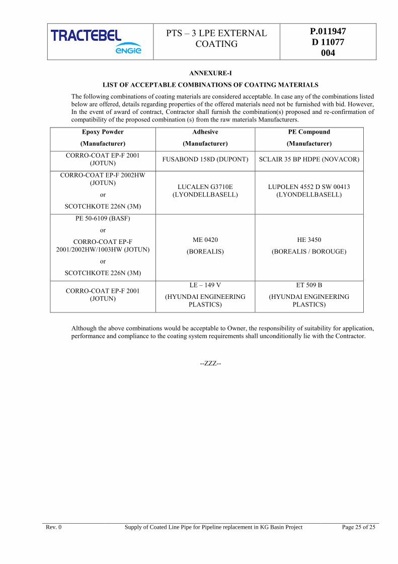
PTS – 3 LPE EXTERNAL
COATING
P.011947
D 11077
004
Rev. 0 Supply of Coated Line Pipe for Pipeline replacement in KG Basin Project Page 25 of 25
ANNEXURE-I
LIST OF ACCEPTABLE COMBINATIONS OF COATING MATERIALS
The following combinations of coating materials are considered acceptable. In case any of the combinations listed
below are offered, details regarding properties of the offered materials need not be furnished with bid. However,
In the event of award of contract, Contractor shall furnish the combination(s) proposed and re-confirmation of
compatibility of the proposed combination (s) from the raw materials Manufacturers.
Epoxy Powder
(Manufacturer)
Adhesive
(Manufacturer)
PE Compound
(Manufacturer)
CORRO-COAT EP-F 2001
(JOTUN) FUSABOND 158D (DUPONT) SCLAIR 35 BP HDPE (NOVACOR)
CORRO-COAT EP-F 2002HW
(JOTUN)
or
SCOTCHKOTE 226N (3M)
LUCALEN G3710E
(LYONDELLBASELL)
LUPOLEN 4552 D SW 00413
(LYONDELLBASELL)
PE 50-6109 (BASF)
or
CORRO-COAT EP-F
2001/2002HW/1003HW (JOTUN)
or
SCOTCHKOTE 226N (3M)
ME 0420
(BOREALIS)
HE 3450
(BOREALIS / BOROUGE)
CORRO-COAT EP-F 2001
(JOTUN)
LE – 149 V
(HYUNDAI ENGINEERING
PLASTICS)
ET 509 B
(HYUNDAI ENGINEERING
PLASTICS)
Although the above combinations would be acceptable to Owner, the responsibility of suitability for application,
performance and compliance to the coating system requirements shall unconditionally lie with the Contractor.
--ZZZ--
PTS - INTERNAL EPOXY
COATING
P.011947
D 11077
005
VENDOR LOGO
IRCA LOGO
PIPELINE REPLACEMENT IN KG BASIN PROJECT
TRACTEBEL ENGINEERING PVT. LTD.
PARTICULAR TECHNICAL SPECIFICATION –
COATING –
INTERNAL EPOXY
RERT
DOC. NO. P.011947-D-11077-005
0 29.04.2019 Issued for Procurement Rajveer Panwar Nirjhar Chakrabarti SK Hussain
Rev. Date Subject of revision Prepared By Checked By Approved BY

PTS - INTERNAL EPOXY
COATING
P.011947
D 11077
005
Rev. 0 Supply of Coated Line Pipe for Pipeline replacement in KG Basin Project Page 1 of 1 Page 1 of 1
TABLE OF CONTENTS
1.0 GENERAL ............................................................................................................................... 1
2.0 SCOPE ................................................................................................................................... 1
3.0 INSTRUMENTATION SYSTEM SUMMARY .............................................................................. 1
4.0 FUNCTIONAL REQUIREMENT ................................................................................................ 2
5.0 MATERIAL SPECIFICATION .................................................................................................. 2
6.0 PREPARATION OF PIPE SURFACE PRIOR TO COATING ....................................................... 4
7.0 COATING PROCEDURES ........................................................................................................ 5
8.0 INSPECTION AND TESTING .................................................................................................. 5
9.0 COATING APPLICATOR QUALIFICATION .............................................................................. 6
10.0 PRE-PRODUCTION QUALIFICATION..................................................................................... 6
11.0 REPAIRS ................................................................................................................................ 6
12.0 MARKING .............................................................................................................................. 7
13.0 DOCUMENTATION ................................................................................................................. 7
14.0 QUALITY ASSURANCE ........................................................................................................... 7
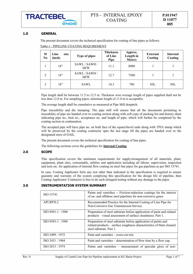
PTS - INTERNAL EPOXY
COATING
P.011947
D 11077
005
Rev. 0 Supply of Coated Line Pipe for Pipeline replacement in KG Basin Project Page 1 of 7 Page 1 of 1
1.0 GENERAL
The present document covers the technical specification for coating of line pipes as follows:
Table-1 : PIPELINE COATING REQUIREMENT
Sl
No
Line size
(inch) Type of pipes
Thickness
of Line
Pipe
Approx.
Length in
Meters
External
Coating
Internal
Coating
1 18” SAWL / SAWH /
HFW 11.1 8000 √ √
2 18” SAWL / SAWH /
HFW 12.7 7500 √ √
3 18” SAWL 14.3 780 NIL NIL
Pipe length shall be between 11.5 to 12.5 m. Thickness wise average length of pipes supplied shall not be
less than 12.0 m. For sampling pipes, minimum length of 11.0 m is acceptable.
The average length shall be cumulative as measured at Pipe Mill despatch.
Pipe traceability and die stamping: The pipe mill will ensure that all the documents pertaining to
traceability of pipe are handed over to coating section along with soft copy of packing list and history sheet
indicating pipe no., heat no., acceptance no. and length of pipe, which will further be completed by the
coating section in continuation.
The accepted pipe will have pipe no. on both face of the square/bevel ends along with TPIA stamp which
will be preserved by the coating contractor upto the last stage till the pipes are handed over to the
designated store of GAIL.
The present document covers the technical specification for coating of line pipes.
The following sections cover the guidelines for Internal Coating
2.0 SCOPE
This specification covers the minimum requirements for supply/arrangement of all materials, plant,
equipment, plant sites, consumable, utilities and application including all labour, supervision, inspection
and tests etc. for application of internal flow coating on steel line pipes for gas pipelines as per ISO 15741.
In case, Coating Applicator feels any test other than indicated in the specification is required to ensure
guaranty and warranty of the system complying this specification for the design life of pipeline, then
Coating Applicator/ Contractor is free to do such stringent testing without any damage to the pipes
3.0 INSTRUMENTATION SYSTEM SUMMARY
ISO 15741 Paints and varnishes -- Friction-reduction coatings for the interior
of on- and offshore steel pipelines for non-corrosive gases
API RP5L2 Recommended Practice for the Internal Coating of Line Pipe for
Non-Corrosive Gas Transmission Service.
ISO 8501-1 : 1988 Preparation of steel substrate before application of paint and related
products – visual assessment of surface cleanliness. Part 1.
ISO 8503-1 : 1988 Preparation of steel substrate before application of paints and
related products – surface roughness characteristics of blast cleaned
steel substrate. Part 1.
ISO 2409 : 1972 Paint and varnishes – cross-cut test.
ISO 2431 : 1984 Paint and varnishes – determination of flow time by a flow cup.
ISO 2813 : 1974 Paints and varnishes – measurement of specular gloss of non-
PTS - INTERNAL EPOXY
COATING
P.011947
D 11077
005
Rev. 0 Supply of Coated Line Pipe for Pipeline replacement in KG Basin Project Page 2 of 7 Page 2 of 1
metallic paint films.
ISO 2812 : 1974 Paint and varnishes – determination of resistance to liquids.
ISO 2808 : 1974 Paints and varnishes – determination of film thickness.
ISO 2811 : 1974 Paints and varnishes – determination of density.
ISO 3233 : 1998 Paints and varnishes-determination of percentage volume of non-
volatile matter by measuring the density of a dried coating
ISO 3251 Paints, varnishes and Plastics- determination of non-volatile matter
content
ISO 6860 : 1984 Paints and Varnishes: Bend test(conical mandrel)
ISO 7253 : 1996 Determination of resistance to neutral salt spray(fog)
3.1 Terms And Definitions
GTS means “ General Technical Specification 740/GTS/404 Rev.0 ” and
all documents it refers to.
PTS means the present “ Particular Technical Specification P.011947 D
11077 005” and all its appendices, if any.
OWNER Shall mean “GAIL (INDIA) LIMITED.”, being the Purchaser of Line
Pipes
CONSULTANT /
OWNER
REPRESENTATIVE
Shall means “ TRACTEBEL Engineering Pvt. Limited ” / The
company nominated by the owner to design the natural gas transport
or distribution system and to specify the equipment
TPIA means the Third Party Inspection Agency
MANUFACTURER means the Manufacturer of the pipes as well as its sub-contractor(s).
4.0 FUNCTIONAL REQUIREMENT
4.1 The pipes shall be lined with liquid epoxy internal coating conforming to ISO 15741. The coating material
shall typically be two pack epoxy paint. The product information like product data sheet, safety data sheet
shall be furnished. Material to be used shall be supplied with marked with following minimum information.
The entire instrumentation system will be designed for the following site conditions:
Manufacturing Standard
HSE Information
Receiving Inspection Acceptance
Storage Instructions
Application Procedure
Batch number & Date of Manufacturing
4.2 The minimum dry film thickness shall be 110 (+20, -0) microns above the peaks in the profile of the
substrate.
4.3 The coating roughness shall be < 10 microns.
4.4 The internal Coating cutback shall be 50 mm ± 5 mm.
5.0 MATERIAL SPECIFICATION
PTS - INTERNAL EPOXY
COATING
P.011947
D 11077
005
Rev. 0 Supply of Coated Line Pipe for Pipeline replacement in KG Basin Project Page 3 of 7 Page 3 of 1
The coating materials shall be fully tested and certified in accordance with ISO15741, the colour shall be
red-brown.
The coating shall fulfill all requirements both on test panels and on coated pipes
5.1 Components
The epoxy paint shall comprise the following components:
1. Epoxy base (epoxy resin, pigments, extenders, additives and organic solvent)
2. Curing agent (epoxy aliphatic/cyclo-aliphatic amine or polyamide).
Base and curing agent shall not contain fatty acids, oils, paraffin or chlorinated plasticizers, fatty acid
esters, 2.3.dihydro-1.1.3.-trimethyl-3phenyl-1H-Indene (C18H20) or similar and other substances which
can contaminate the natural gas. This implies polar high molecular weight components with very low
vapour pressure and diffusion rate of the components within the paint film.
5.2 Properties of Coating Materials
Epoxy coating shall be thixotropic and have a volume of solids (non thinned paint).
Coatings shall flow, with no solids retention (refer to ASTM D 185, Mixed Paints), through a 90 microns
sieve.
The manufacturer of the coating shall specify and communicate the pot-lift, the dry-to handle time (refer to
ASTM D 1640) and the complete drying time (ISO 1517) at temperature intervals of 10˚C (from 0˚C to
60˚C) and a relative humidity of 85.
The coating shall be suitable for application by airless equipment in the following conditions:
- Metal temperature between 10˚C and 60˚C.
- Ambient temperature between 10˚C and 45˚C.
- Ambient relative humidity up to 85%.
5.3 The material being proposed shall have been applied successfully in at least one project of pipe size 18”
and length 50 Km in last five years. The coating material shall be qualified as per ISO 15741, latest edition
and all qualification testing shall be performed at an in-house laboratory. If in-house laboratory not
available with manufacture the manufacturer shall perform all testing as per QAP in external laboratory
under third party witness in independent NABL accredited laboratory within India or independent external
Laboratory approved by equivalent national authority/board of Manufacturer's country shall be submitted
for review and acceptance for coating material qualification.
5.4 The coating manufacturer shall obtain the results in the form of a full qualification report showing test
method, frequency and results for following inspection & test as per approved QAP’s for the proposed
coating procedure:
Visual Inspection
Pin hole testing (on glass panel)
Adhesion (on steel panel)
Buchholz Hardness (Glass and steel panel)
Curing test
Bend test (conical mandrel)
Wet film thickness & DFT
Coating roughness
Coating applicator shall test each batch of material to be used for coating of the line pipes every shift in
regular production for the establishing following properties of the material:
Specific Gravity

PTS - INTERNAL EPOXY
COATING
P.011947
D 11077
005
Rev. 0 Supply of Coated Line Pipe for Pipeline replacement in KG Basin Project Page 4 of 7 Page 4 of 1
Viscosity (mixed)
5.5 Control of Raw Materials
5.5.1 Identification
Each batch of the paint shall be clearly identified and all necessary batch certification shall be available.
IR-spectre shall be part of the batch certification. IR-spectra shall be subject to random control by coating
contractor.
5.5.2 Package and Storage
The drums containing paints shall be kept in their original packing of the coating manufacturer until the
moment of use. The storerooms shall be protected so that the recommended storage temperature range as
indicated by the manufacturer, is maintained.
6.0 PREPARATION OF PIPE SURFACE PRIOR TO COATING
6.1 Surface Profile
Prior to preparation of pipe surface, all pipes shall be visually examined for dents, laps, defect bevels and
other obvious defects in order to avoid coating unserviceable pipes. Defective pipes shall be noted and, if
they cannot be repaired by light grinding, they shall be removed from the coating area.
To achieve the recommended internal blast profile an auto blast cleaning method shall be used for surface
preparation. A constant blast cleaning speed and a controlled process is essential to obtain the desired
profile. The final surface blast profile will influence the coating smoothness.
Pipe surfaces shall be cleaned to SA 2½ (in accordance with ISO 8502 -3) using suitable grit/ shot, free of
any deleterious contamination or moisture. The surface roughness shall be checked at random and shall be
of the range of 30-60 microns in accordance with ISO 4287-1. Bare pipe after blasting shall be 100%
visually inspected to check defects in internal surface and bevels as per QAP under TPIA witness for
suitable percentage of pipes lot.
6.2 Dust Contamination
Removal of dust after blast-cleaning is important as a layer of dust will lead to poor adhesion of the coating
to the steel.
The dust level on the blast-cleaned surface shall be of Class 1 or better in accordance with ISO 8502-3.
Before coating, the pipe surface shall be cleaned from all dust and foreign matter using clean dry
compressed air or vacuum cleaning. Compressed air to be used for drying and blasting shall be free from
water and aerosol oil tested in accordance with ASTM D4285.
6.3 Washing
Immediately prior to the initial blast cleaning, all pipe shall be washed to remove any loose mill scale, rust,
water, oil, graphite, grease marking materials and other foreign materials that adversely affect the quality of
the coating. Initial fresh water washing shall be carried out to ensure removal of soluble salts. Any pipe
with contamination such as oil, grease, temporary coatings or other substances which may contaminate the
blast cleaning medium left after washing shall be conspicuously marked and set aside for inspection by
Owner’s/Owner’s Representative.
After the washing process and prior to blast cleaning rinse with clear water to remove any harmful residue
of cleaning agents and/or detergents.
The cleaning method shall be tested and documented for the actual coating method during qualification
testing.
6.4 Pre-heating
In internal surface temperature of the pipe shall prior to commencement of the internal coating shall be 5°C
above measured dew point. In case the internal surface temperature of the pipe is below this requirement,
the internal surface shall be heated using hot air (gas flame is not permitted). The internal surface
temperature will not exceed 35°C or as per instructions of internal paint coating supplier.
PTS - INTERNAL EPOXY
COATING
P.011947
D 11077
005
Rev. 0 Supply of Coated Line Pipe for Pipeline replacement in KG Basin Project Page 5 of 7 Page 5 of 1
6.5 Abrasive Cleaning
Pipes shall be shot blasted to minimum Sa 2 ½ (ISO 8502-3). The finish shall be maintained until the
moment of coating.
After completion of abrasive cleaning operations, the steel surface must be thoroughly checked. Any
slivers, swabs, burrs, lamination and gouges shall be removed by grinding. After grinding, the remaining
wall thickness shall comply with the requirements of minimum wall thickness according to MTO and OS-
F101. All visible dust and solid particles shall be removed.
Before coating, the pipe surface shall be cleaned from all dust and foreign matter using clean dry
compressed air or vacuum cleaning. The compressed air shall be free of any trace of oil.
All pipes shall be tested for salt contamination after blast cleaning unit. One test shall be carried out on
each pipe. An approved salt meter (SCM 400 or equivalent) shall be used to carry out salt tests and shall be
calibrated in accordance with the equipment manufacturer’s recommendations. Any pipe having salt
contamination exceeding 2 μg/cm² shall be either re-blasted or de-ionized water washed and then
rechecked for salt contamination.
7.0 COATING PROCEDURES
The components shall be mixed thoroughly in accordance with the manufacturer’s directions.
The paint shall be free of any lumps or skinning at the moment of application.
The viscosity of the mixed paint shall be monitored, before it is applied, by means of suitable equipment
and adjusted if necessary.
7.1 Coating Application
After blast cleaning and during paint application
The steel temperature shall be kept at a temperature of at least 3˚C above dew point
The metal temperature shall be between 15˚C and 60˚C. No heating of pipes between blast cleaning and
paint application shall be performed.
The ambient temperature shall be between 10˚C and 45˚C.
The ambient relative humidity shall be maximum 85%.
The coating shall be sprayed continuously and uniformly onto the whole surface to be coated using airless
spray equipment.
The coating shall be continuous for the full length of pipe, except for an area at each end of 50 mm ± 5
mm.
7.2 Curing
The pipes shall be touch dry before any handling. Handling procedures must reflect curing of the coating.
The curing method shall be tested and documented. The coating shall be cured at a temperature
recommended by the paint manufacturer.
7.3 Dry Thickness of the Applied Coating
Dry thickness of coating on the pipe body and pipe seam shall be between 110 (+20,-0) microns and
roughness 10 µm.
Four spot measurements shall be taken at 90 degree intervals around the inside diameter. Each spot
measurement shall be within the thickness and roughness range as specified above.
8.0 INSPECTION AND TESTING
The Inspection and Testing comprises of testing to be carried out as per approved QAP and ISO-15741,
latest edition and shall comprise of the following:
- Material testing and review of test certificates as per ISO-15741.
PTS - INTERNAL EPOXY
COATING
P.011947
D 11077
005
Rev. 0 Supply of Coated Line Pipe for Pipeline replacement in KG Basin Project Page 6 of 7 Page 6 of 1
- Application process testing for surface preparation.
- Application process testing of coating being applied.
Final test after application of coating
The inspection of testing shall comprise of the following tests:
- Visual inspection
- Pin hole test(on glass panel)
- Bend test
- Buchholz hardness test
- Curing test
- Adhesion test
- Roughness test
Any other test as specified in ISO 15741.
9.0 COATING APPLICATOR QUALIFICATION
9.1 Past reference of identical coating jobs with names of consultant, client, job reference and year of
completion for at least one completed job in past five years along with acceptance certificate regarding the
Coating Applicator shall be submitted to the Owner/ Consultant.
9.2 Copy of certificate approved by Third Party Inspection Agency/ Client in past showing the use of proposed
raw material from a single manufacturer/ brand or different manufacturers/ brand shall be submitted to the
Owner/ Consultant.
10.0 PRE-PRODUCTION QUALIFICATION
Any coating, material and coating procedure proposed in relating to this specification, shall be qualified
prior to and during the plant start-up phase through suitable tests and inspection carried out at the
Contractor’s workshop. The qualification document shall be prepared and supplied to Company by
Contractor prior to coating production commencement.
Minimum 3 pipes shall be used for the pre-production test. Inspection and testing shall be carried out and
meet all requirements in this Specification.
Detailed procedure/ write up covering each step, starting from selection of raw material, preparation for
coating, detailed coating steps, including First Day Production test, in-house inspection including physical
test for viscosity, density, pot life, infrared spectrogram and appearance, rejection and repair procedure
shall be furnished by Coating Applicator for review/approval of Owner/Consultant. Defective or damaged
coating shall be repaired by the Applicator.
All qualification tests shall be conducted at National Accreditation Board for Testing and Calibration
Laboratories (NABL) approved laboratory within India or Independent external Laboratory approved by
equivalent national authority/board of Manufacturer's country. Test results at both the testing facilities (i.e.
manufacturer's test facility and external laboratory) comply with specification requirements.
10.1 First Day Production Coating Prior to start of production, trail “First Day Production Coating” shall be
carried out by the Coating Applicator to prove that his plants (machinery and manpower), materials and
coating procedure result in a quality of end product conforming to the functional requirements and
properties as stated in the relevant technical specifications, standards and material manufacturer’s
recommendations. At least 25 (twenty five) test pipes shall be coated in accordance with the approved
procedure and relevant standards of all raw material Batch / Lot. Owner/ Consultant Representative shall
select 3 numbers of test pipes at random out of the above mentioned 25 pipes.
11.0 REPAIRS

PTS - INTERNAL EPOXY
COATING
P.011947
D 11077
005
Rev. 0 Supply of Coated Line Pipe for Pipeline replacement in KG Basin Project Page 7 of 7 Page 7 of 1
The maximum allowable area per repair is 40 cm2 and maximum 2 repairs are allowed per single pipe.
Pipes with damaged areas larger than the maximum permitted repair areas shall be rejected, stripped and
recoated.
The Contractor shall submit detailed procedures for coating repairs. All coating repair procedures shall be
qualified.
12.0 MARKING
Coating Applicator shall place marking on the inside surface of the coating at one end of the coated pipe,
and marking shall indicate, but not limited to the following information:
Pipe number, Heat number
Diameter & Wall thickness
Coated pipe number
Color band
Any other information considered relevant by Owner/ Consultant.
Pipe Manufacturer Name
Inspection Mark/Punch
13.0 DOCUMENTATION
In addition to the documentation requirements as per ISO 15741, Coating Applicator/ Contractor shall
submit following documents to the Owner/ Owners representative/ Consultant for review/ approval:
Certification that the formulation of the supplied material is exactly the same as that used for the
laboratory qualification.
Coating Application Procedure as per clause 6 of this specification.
Past track documents as per clause 9 of this specification.
14.0 QUALITY ASSURANCE
14.1 All the inspection and testing shall be carried out as per Quality assurance plan as minimum.
14.2 All QA/QC documentation shall be as per ISO 9001 and approved by Owner/ Consultant.
14.3 If any contradiction between this procedure and QAP, most stringent shall be followed with prior approval
from owner / consultant.
-X-X-X-

ERRATA to
GENERAL TECHNICAL SPECIFICATION (GTS) No : 740/GTS/404 – LINE PIPES SPECIFICATION
Para 4.53: Replace § 9.8.5 by § 9.8.3
Para 9.11.3.3: Typo - the word API %L to be replaced by API 5L
Para 9.12.1.: Typo - the “100” to be deleted
Para 12.2: Typo – the word eliding to be replaced by welding

GENERAL TECHNICAL
SPECIFICATION
740
GTS
404
LINE PIPES SPECIFICATION
FOR GAS TRANSMISSION AND DISTRIBUTION PIPING SYSTEM
ONSHORE SERVICE
5 21/06/13 Updated in conformity with API 5L 45th edition December 2012 MRT NC MRT
4 14/09/09 Logo Changed VA DNS NC
3 15/09/08 Logo Changed PK DNS NC
2 06/10/04 Updated in conformity with API 5L edition March 2004 GAR DKB DKB
1 04/10/04 Updated in conformity with API 5L edition March 2004 GAR DKB DKB
0 03/08/04 Change Company logo and numbering of document MRY DKB MRY
Rev. Date Subject of revision Author Checked Approved
GENERAL TECHNICALSPECIFICATION
740GTS404
Rev.5 – 21.06.13 Page 1 of 1
TABLE OF CONTENTS
1. SCOPE ................................................................................................................................... 32. CONFORMITY ......................................................................................................................... 32.1 Units of measurement ............................................................................................................. 33. NORMATIVE REFERENCES ....................................................................................................... 34. TERMS AND DEFINITIONS ....................................................................................................... 34.9 COW pipe .............................................................................................................................. 44.11 COWL pipe ............................................................................................................................. 44.17 EW pipe ................................................................................................................................. 44.23 HFW Pipe ............................................................................................................................... 44.34 LFW Pipe ............................................................................................................................... 44.53 SAWH pipe ............................................................................................................................. 44.59 Submerged-arc welding ........................................................................................................... 55. SYMBOLS AND ABBREVIATED TERMS ....................................................................................... 56. PIPE GRADE, STEEL GRADE AND DELIVERY CONDITION ............................................................ 57. INFORMATION TO BE SUPPLIED BY THE PURCHASER ................................................................ 58. MANUFACTURING ................................................................................................................... 58.1 Process of Manufacture ........................................................................................................... 58.3 Starting Material ..................................................................................................................... 68.4 Tack Welds ............................................................................................................................ 68.6 Weld seams in SAWH pipe ....................................................................................................... 78.9 Cold Sizing and Cold Expansion ................................................................................................ 78.10 Coil / Plate End Welds ............................................................................................................. 89. ACCEPTANCE CRITERIA ........................................................................................................... 89.1 General .................................................................................................................................. 89.2 Chemical Composition ............................................................................................................. 89.3 Tensile Properties ................................................................................................................... 99.8 CVN IMPACT TEST FOR PSL 2 PIPE: ........................................................................................ 109.11 Dimensions, Mass, and Tolerances .......................................................................................... 119.12 Finish of pipe ends ................................................................................................................ 119.13 Tolerances for the Weld Seam ................................................................................................ 1210. INSPECTION ........................................................................................................................ 1210.1 Type of Inspection and Inspection Documents ......................................................................... 1210.2 Specific Inspection ................................................................................................................ 1311. MARKING ............................................................................................................................. 1411.1 General ................................................................................................................................ 1411.2 Pipe Marking ........................................................................................................................ 1412. COATINGS AND THREAD PROTECTION ................................................................................... 1512.1 Coatings and Linings ............................................................................................................. 1512.2 Thread Protectors ................................................................................................................. 1513. RETENTION RECORDS .......................................................................................................... 1614. PIPE LOADING...................................................................................................................... 1615. WARRANTY (NEW CLAUSE) ................................................................................................... 18
GENERAL TECHNICALSPECIFICATION
740GTS404
Rev.5 – 21.06.13 Page 1 of 38
INTRODUCTION
The present Specification has to be read in conjunction with the API 5L forty-fifth edition, its addendum(December 2012) and the Particular Technical Specification (PTS) attached to the material requisition.
The present specification intends to clarify, confirm, complete or modify certain paragraphs of the API 5Lspecification. Clauses in API 5L specification not mentioned remain unaltered and are fully applicable. Ifonly part of a clause in API 5L is altered by the present specification the remaining of any such clause shallremain applicable
Unless otherwise stated by the Purchaser, The Third Party Inspection is required during the manufacture,inspection and testing of the order. The Third Party Inspection Agency shall be approved by the Purchaseras qualified to monitor product quality and all other activities related to production of the order. TheOwner’s representative (quality inspector) shall have unrestricted access at all times while activities relatedincluding casting, rolling and other fabrication processes and testing works at assigned locations withinManufacturer facilities. Manufacturer shall provide suitable office space, fax telephone and broad bandinternet connection to the Owner’s representative and the Third Party Inspection Agency. The Manufacturershall provide to the inspector(s) all reasonable facilities, including dry and clean pipes to satisfy theinspector(s) that pipes are being fabricated in accordance with the API 5L and present GTS specifications.The Manufacturer shall provide reasonable advance notice of when production, inspection or testing shallbe performed.
The Manufacturer shall clearly specify all modifications or alternatives to the present specification. Eachmodification has to be submitted for approval to the Purchaser. and to the Third Party Inspection Agency
The complete production cycle shall be supervised by the Third Party Inspection Agency.
A technical audit will be executed during a sample production run.
The steel Manufacturer’s specification, the manufacturing procedure itself and the test laboratories shall beapproved and registered by the Third Party Inspection Agency.
The Third Party Inspection Agency shall verify the equipment test control of the Manufacturer, inparticular the calibration status of the equipment.
If during the production process problems concerning the quality arise, Third Party Inspection Agencymay request additional tests.
The Manufacturer has to specify whether or not his production process is certified according to “ISO” orother approved standard.
The Manufacturer shall be certified ISO 9001, ISO/TS 29001 or approved equivalent.
The Manufacturer shall be a certified API licensee and should and have obtained a valid API monogramlicense.
The Manufacturer has to provide a detailed flow chart of all manufacturing and inspection procedures andfollowing information will be made available:
Technical description of the production;
Schedule of the fabrication operations;
Inspection schedule during the manufacturing;
Codes and Standards applicables for the inspection (or the reference numbers if the inspections areperformed according to an internal QAM) and mentioning if the inspections are supervised or not byThird Party Inspection Agency;
Level of the inspector (see Annex E § E.1 Qualification of personnel in API 5L 45th edition;
Inspection report.

GENERAL TECHNICALSPECIFICATION
740GTS404
Rev.5 – 21.06.13 Page 2 of 38
PROPERTIES OF THE PIPES
Product Specification Level (PSL) : PSL2
Max. operating pressure : See PTS
Max. operating temperature : 60 oC
steel grade : See PTS
Ø outside (Nominal) : See PTS
wall thickness (Nominal) (WT) : See PTS
Calculation according to ASME B31.8 with :
design factor : See PTS
negative tolerance for WT : zero millimeter (0 mm)
corrosion allowance : zero millimeter (0 mm) See PTS
yield strength : See PTS
weld efficiency level : 100%
lengths of the pipes : Nominal length shall be at least twelve metres(12 m) but not more than transportable by RoadTrucks or railwroad according to prevailinglegislation. (See PTS).

GENERAL TECHNICALSPECIFICATION
740GTS404
Rev.5 – 21.06.13 Page 3 of 38
1. SCOPE
ADD:
The present specification is applicable to steel grade < X 80 (L555) / and for operating pressure < 100 bar(1450 PSI). All Line Pipes shall exclusively comply with “Specification Level PSL 2” and to allrequirements thereof.
2. CONFORMITY
2.1 Units of measurement
All data related to this specification should be expressed in SI units.
3. NORMATIVE REFERENCES
ADD:
API RP 5L1, Recommended Practice for Railroad Transportation of Line Pipe.
API RP 5LW, Recommended Practice for transportation of Line Pipe on Barge and Marine Vessels.
4. TERMS AND DEFINITIONS
GTS: means the present <<General Technical Specification740/GTS/404>>and all documents it refers to.
Inspection Agency orThird Party Inspection Agency (TPIA): means the Inspection agency to be appointed by
Manufacturer.
Manufacturer: means the Manufacturer of the pipes as well as its sub-contractor(s) including the applicator(s) of coating(s).
Normative: Indicates mandatory requirement.
Owner or Purchaser: shall mean the CLIENT, being the Purchaser of pipes.
PTS: means <<Particular Technical Specifications>> and all itsappendices, if any.
Single Step SAWH Pipe: Production of helical pipe where forming and final weldingoccur on the pipe-making machine.
Shall: Used to indicate that a provision is mandatory.
Should: Used to indicate that a provision although non-mandatory isrecommended as good practice. Approval is required fromPurchaser to deviate from the provision.
Two-step SAWH Pipe: Production of helical pipe where forming and tack weldingare performed on a pipe –making machine and final weldingis performed as a separate downstream process.
GENERAL TECHNICALSPECIFICATION
740GTS404
Rev.5 – 21.06.13 Page 4 of 38
4.9 COW pipe
Combination welded pipe
ADD: “The validity of the qualification procedures shall be approved by the Purchaser and the inspectionagency”.
Clause should amended as: The double seams (two longitudinal seams) produced by a combination of gasmetal-arc and submerged-arc welding is not allowed.
4.11 COWL pipe
Combination longitudinal welded pipe
ADD: “The validity of the qualification procedures shall be approved by the Purchaser and the inspectionagency”.
Clause should amended as: The double seams (two longitudinal seams) produced by a combination of gasmetal-arc and submerged-arc welding is not allowed.
4.17 EW pipe
Electric welded pipe
Only high frequency electric-welding is permissible
4.23 HFW Pipe
High Frequency Welding Pipe
The welding current shall be performed with a minimum frequency of 100 kHz.
4.34 LFW Pipe
Low Frequency Electric Welded Pipe
The welding current shall be performed with a minimum frequency of 100 kHz.
4.53 SAWH pipe
Submerged-arc helical welded pipe
ADD:
At end of Clause, add:
Prior to welding, each edge of the strip shall be ultrasonically examined for laminations over a width of 25mm along its longitudinal edges.
Welds shall be inspected on their full length by ultrasonic method according to § 9.8.5.
The transition between parent metal and weld deposit shall not display undercutting.
The over thickness of the weld deposit shall not exceed the requirement of table below.

GENERAL TECHNICALSPECIFICATION
740GTS404
Rev.5 – 21.06.13 Page 5 of 38
Specified wall thicknessmm
Over thickness of weld deposit in mm
T< 15
T>15
2
3,2
Table: Maximum over thickness of the weld deposit of spiral welded pipes
The edges of joints shall be held during welding so that the tolerances of table below are not exceeded in thecompleted joint.
Section thicknessmm
Tolerance
Up to 13 mm (0.512 in)
Over 13 mm (0.512 in)
¼ t
3,2
Table: Maximum offset of edges of completed joint.
4.59 Submerged-arc welding
SAW
Add: “The whole weld shall be done by automatic welding”
5. SYMBOLS AND ABBREVIATED TERMS
ALL CLAUSES ARE APPLICABLE
6. PIPE GRADE, STEEL GRADE AND DELIVERY CONDITION
All clauses related to pipe grade for PSL 2 are applicable and the present specification is applicable to pipe /steel grade < X 80 (L 555).
7. INFORMATION TO BE SUPPLIED BY THE PURCHASER
All clauses related to pipe grade for PSL 2 are applicable refer also to purchase order for additionalrequirement
8. MANUFACTURING
8.1 Process of Manufacture
GENERAL ADDITIONAL REQUIREMENTS:
The pipe manufacturer, the pipe-mill and all potential subcontractors (such as steel Manufacturer, rolling-mill, heat treatment, weld fabrication...) shall necessarily be indicated in the tender.
No changes will be accepted after eventual order except in case of justified Force Majeure. In that case theasked changes will be supported by a technical file transmitted to the Purchaser for approval.
A description of the pipe manufacturing process shall be included in the tender.
The Third Party Inspection Agency reserves himself the right to audit for agreement the manufacturingprocess and control method of the Manufacturers and subcontractors. All the costs resulting from such auditshall be taken over by the Manufacturer with the exception of wages and travel expenses.
GENERAL TECHNICALSPECIFICATION
740GTS404
Rev.5 – 21.06.13 Page 6 of 38
All welding operations are subject to prior qualification of applicable welding procedures, weld operatorsand/or welders.
The validity of the qualification procedures shall be submitted for approval to the Purchaser and the ThirdParty Inspection Agency.
The Manufacturer shall give a technical description of the manufacturing method, which may have aninfluence on the quality of the pipe.
Welding Parameters records
All basic welding parameters actually used during the welding process shall be continuously recorded byautomatic devices for each length of pipe.
These records shall be at disposal of the Third Party Inspection Agency and Purchaser for review atdiscretion of Third Party Inspection Agency and Purchaser before acceptance of the pipe.
Length of Pipes without records shall be rejected.
8.3 Starting Material
8.3.1 At the end of this paragraph add the following;
Except otherwise specified on the purchase order the pipe delivered to this specification as normalized orquenched and tempered is not allowed.
“The steel manufacturing method shall be given in the tender and, has to be approved by the Purchaser andthe inspection agency”.
“Only fully killed steel is acceptable”.
8.3.3 The clause should be modified as followed:
“For PSL 2 pipe, only fully killed made according to fine practice is acceptable”.
8.3.5 The minimum width of the coil or plate for the manufacture of helical seam pipe shall be more than 1.2times the specified outside diameter of pipe.
8.3.8 Add;
The producers of slab/skelp/coil used for the production of pipe require Purchaser approval. The approvalmay include pre-qualification, production, inspection, or testing of slab/skelp/coil.
When niobium is 0.020 % and when the ambient temperature is 5o C, gas cutting and scarfing of slabsshall be performed at temperature 120oC to minimize the risk of thermal cracking.
Skelp/coil thickness shall be controlled by continuous gamma or X-ray devices. Skelp/coils rolling andaccelerated cooling shall be adequately instrumented to ensure proper control of furnace/rollingtemperature, rolling reduction and post-rolling cooling rate
8.4 Tack Welds
Add;
Tack welding as applicable in SAHW pipe shall be continuous.
GENERAL TECHNICALSPECIFICATION
740GTS404
Rev.5 – 21.06.13 Page 7 of 38
8.6 Weld seams in SAWH pipe
All pipe production shall employ fully automatic equipment. For single –step SAWH pipe, automatic seamtracking and gap control should be employed and electrical grounding shall not be through the machinebody.
The longitudinal edges of the skelp / coil shall be machined to remove a minimum width of material equalto one times the skelp/coil thickness from each edge in preparation for welding. Run-on and run-off weldtabs shall be of sufficient length so that the weld arc is stable prior to entering the pipe length and thecomplete weld pool has left the pipe length prior to weld stop.
A program of moisture control of the welding flux shall be maintained through the use of moisture proofsealed storage and/or by baking and/or by holding the flux at a temperature recommended by the fluxmanufacturer in order to maintain the flux moisture content below 0.05% or diffusible hydrogen in the weld< 5 ml/100 g of the weld metal. All welding consumables shall be identifiable and traceable tomanufacturer’s batch certificate.
The use of recycled crushed flux slags (previously melted) is not permitted.
A Welding Procedure Specification (WPS) and a Procedure Qualification Record (PQR) shall be submittedwith the Manufacturing Procedure Specification for approval. The WPS and PQR shall be established inaccordance with ASME SEC IX. Previously qualified WPS and PQR are valid provided all essentialvariables identified in Annex D, D.2.2 of API SPEC 5L are within the stated limits. The following essentialvariables shall also apply:
a) Increase in parent metal carbon of more than 0.02%.
b) Change in parent metal supplier.
c) Change on groove dimensions outside tolerances in qualified WPS,
d) Change in aim ratio of recycled to new flux greater than 15%.
e) Change in alignment and/or groove configuration.
f) Change in manufacturer of welding consumables (wire and flux) or in combination.
g) Number of wires or change in welding equipment.
h) Change in method or temperature of preheat and/or interpass.
Once the PQR has been approved any variation regarding any essential variables, shall be subject to a newPQR and qualified WPS to be approved by Purchaser.
8.9 Cold Sizing and Cold Expansion
The pipe manufacturing method shall be given in the offer and has to be approved by the Purchaser andThird Party Inspection Agency.

GENERAL TECHNICALSPECIFICATION
740GTS404
Rev.5 – 21.06.13 Page 8 of 38
8.9.1 When cold sizing / expansion is applied, it shall be mechanically cold expanded for the full length. Theexpansion measured on the circumference shall range between 0.3 to 1.5 percent of the value measuredbefore expansion. The amount of expansion shall be measured on at least 3 pipes per 8 hour shift.
8.9.3 At the end of this paragraph add the following;
“Pipe furnished to this specification shall be either non expanded or cold expanded at the option of theManufacturer, unless otherwise specified on the purchase order. Suitable provision shall be incorporated toprotect the weld from contact with the internal expanding mechanical device during mechanical expansion”.
8.10 Coil / Plate End Welds
8.10.2 The clause should be modified as followed;
No skelp end weld is permitted in finished pipes and, if existing, shall be cut out perpendicularly to axis ofpipe so that the “new” pipe end(s) shall be at minimum 304.8 mm (12”) from said skelp end weld before itselimination.
8.10.4 Not applicable
8.10.5 Not applicable
9. ACCEPTANCE CRITERIA
9.1 General
The delegate of the inspection agency reserves the right to select the pipes to be tested.
re-test can only be made after approval of the Purchaser and the inspection agency.
All non conforming chemical or mechanical tests shall be immediately reported to the Purchaser.
9.1.2 The clause should be modified as followed;
Substitution of pipe manufactured as Grade higher than grade specified in the purchase order is not allowed
9.2 Chemical Composition
Add;
For each pipe diameter, grade and wall thickness combination a single aim chemistry shall be followed.
Table 5 (modified) Chemical composition for X70 & X80 steel grade PSL2 welded pipes(Themomechanical-rolled coil or plate and cold forming “M”).
Table 5 (Modified)
PSL 2 Chemical requirementProduct analysis by percentage of weight % maximum
Element (1) X70M steel grade X80M steel gradeC b 0.12 Max 0.10 MaxSi 0.45 Max 0.45 Max
Mn b 1.70 Max 1.85 MaxP 0.025 Max 0.025 MaxS 0.015 Max 0.015 Max
Cu 0.35 Max 0.50 MaxNi 0.30 Max 0.70 Max

GENERAL TECHNICALSPECIFICATION
740GTS404
Rev.5 – 21.06.13 Page 9 of 38
Cr 0.30 Max 0.40 MaxMo 0.15 Max 0.35 MaxV 0.08 Max 0.10 Max
Nb 0.06 Max 0.06 MaxTi 0.06 Max 0.06 Max
Other h, l, j 1 2 j l 1 2
Nb + V + Ti 0.15 Max 0.15 MaxCu + Ni 0.50 Max 0.75 Max
CE (II W) 0.43 Max 0.43 MaxCE (PCM) 0.23 Max 0.23 Max
All footnotes of the table 5 of API 5L are applicable except otherwise noted.
Notes:
b- applicable for X70 and X80 grade. For each reduction of 0.01% below the specified maximum for carbonan increase of 0.05% subject to reduction in C to level 0.08 max
j- Boron content shall be considered in CE (PCM) formula even if it is less than 0,004%.
Additional notes;
(1) Any coil/skelp/plate material supplier will have to propose their best chemical composition to achievethe required mechanical properties of the final product.
(2) Ti/N ratio shall not exceed 3.0.
9.2.3 For pipe with t > 25.00 mm (0.984 m) the chemical composition shall be specified in the ParticularTechnical Specification (PTS).
9.2.5 For PSL 2 pipe with a product analysis carbon mass fraction greater than 0.12% the carbon equivalent,CEIIW, shall be determined using equation;
0.43%) to(limited5156
VMoCrNiCuMnCCE
9.3 Tensile Properties
9.3.2 Add:
The ratio (Rt0,5/Rm) between the measured values of yield strength (Y) at 0.5% elongation of the gaugelength as determined by an extensometer and ultimate tensile strength (T) for the body of each test pipe(product pipe) on which, yield strength and ultimate tensile strength are determined shall not exceed 0.85for Grades X60 and lower. For Grades X65 to X80 included, the same ratio may reach the value of 0.90.
9.3.3 Hardness tests (added)
Vickees Hardness (Hv 10) tests shall be conducted on the metallographic cross section required in table 18of API 5L in accordance with clause H.7.3.3 “Hardness tests”. Indent locations shall conform to Annex H,Figure H.1.b. At least one HAZ hardness indent shall be positioned in the coarse grain structureimmediately adjacent to the fusion line.
Hardness shall conform to the following:

GENERAL TECHNICALSPECIFICATION
740GTS404
Rev.5 – 21.06.13 Page 10 of 38
The Hardness (Hv 10) Base metal, weld metal, and HAZ non sour service
steel grade < X 70 (L485)) < 260
steel grade < X 80 (L555) < 270
9.8 CVN IMPACT TEST FOR PSL 2 PIPE:
9.8.1.3 ModificationFor all base materials and welds:
The CVN Impact test shall be conducted at both ( - ) 200 C & 00 C. Impact test value (For all base materialand weld) shall conform to requirement of Table 8 of Cl. No. 9.8 (CVN Impact test for PSL 2 pipe) API 5L45th Edition.
9.8.2 Pipe body tests
9.8.2.1 Add;
For pipe body and base material the minimum average (of a set of three test pieces) for each pipe body(base material) for grade X80 (L555) shall be as per table 8 of API 5L with an absolute value not less than35j/cm2. In addition the lowest individual value of only one of the three specimens shall not be less than80% of the average value (I.E.28J/CM2).
For the base material, 3 sets of 3 specimens shall be taken per coupon. 2 sets shall be tested at (-) 20°C and1 at 0°C.
9.8.2.2 For all pipes the clause is applicable and the shear fracture arc shall be at least 85% based upon a testtemperature of -200c. (-40 F)
9.8.3 Pipe weld and HAZ tests
For pipe weld and HAZ, 3 sets of 3 transverse specimens shall be taken transverse to the weld.
One set shall be taken with the notch in the HAZ (= Heat Affected Zone) and shall be tested at (-) 20°C
Two sets shall be taken with the notch in the weld, one shall be tested at (-) 20°C and one at 0°C.
In the case of electric welded pipe, only 2 sets will be taken with the tip of the notch in the fusion line. Oneset shall be tested at (-) 20°C and one at 0°C. Its location is verified after metallographic etching.
Acceptance criteria
At 0°C
For all base material, welds and HAZ:
The average value of a set of 3 specimens from a pipe length shall be as per table 8 but with an absolutevalue not less than 35J/cm2 .In addition, the lowest individual value of only one of the three specimens shallnot be less than 80% of the specified average value (i.e. 28 J/cm2).
At - 20°C
For all base material, welds and HAZ:
The average value of a set of 3 specimens from a pipe length shall be as per table 8 with an absolute valuenot less than 35 J/cm2. In addition, the lowest individual value of only one of the three specimens shall notbe less than 80% of the specified average value (i.e. 28 J/cm2).

GENERAL TECHNICALSPECIFICATION
740GTS404
Rev.5 – 21.06.13 Page 11 of 38
9.10 Surface condition imperfections and defects
9.10.2 Undercuts
Undercuts can best located visually and to be tested in accordance with API 5L. The resultant cavity shallnot extend into the pipe body by more than 3 mm (0,125 in).
9.10.3 Arc burns
9.10.3.2 Repair of arc burn shall be approved by Purchaser’s representative. Ground areas shall be inspected bymagnetic particle or dye penetrant methods.
9.10.6 Hard spots
The maximum hard spot hardness shall not exceed 300 Hv10.
9.11 Dimensions, Mass, and Tolerances
9.11.1 Dimensions
9.11.1.1 Except otherwise started in the PTS
Pipe length shall be between 10.0 and 14.0 m. Thickness wise average length of pipes supplied shall not beless than 12.5 m. The average length shall be cumulative as measured at Pipe Mill despatch note.
Overall length tolerance shall be (-) zero and (+) 1 pipe length to complete the Owner’s quantity.
9.11.3 Tolerances for diameter, wall thickness, length and straightness
9.11.3.1 The clause is modified as followed;
For specified outside diameter > 6 inch (168.3mm) the out of roundness at pipe ends will be limited to 3mmand 5mm at pipe body (maximum difference between minimum and maximum diameter).
For outside diameter 6 inch (168.3mm) the value of table 10 shall prevail.
9.11.3.2 The clause is modified as followed;
No negative tolerance is permitted
9.11.3.3 Modification
d) Jointers are not permitted. Annex A Specification for welded jointers of the API %L 45th edition isnot applicable.
9.11.3.4 The tolerances for straightness shall be modified as follows;
The deviation from a straight line for all pipes sizes shall not exceed 12 mm.
9.12 Finish of pipe ends
9.12.1 General
Except otherwise stated in the purchase order the pipes shall be supplied plain ends with end beveled as perclause 9.12.5.2.
Automatically, the 100 following shall apply

GENERAL TECHNICALSPECIFICATION
740GTS404
Rev.5 – 21.06.13 Page 12 of 38
9.13 Tolerances for the Weld Seam
9.13.2.2 For SAW and COW pipes, the following shall apply.
Additionally, the following shall apply:
c) For pipes supplied plain end non beveled (beveled at site) the internal weld bead reinforcement shall beremoved for 100 mm from the pipe ends
d) For girth welds that will be ultrasonically inspected during pipe installation, the outside weld beadreinforcement shall be removed for 180 mm from the pipe ends.
f) Peaking; deviation from circular arc at the weld seam at pipe ends shall not exceed 1.6 mm. Each pipeshall be checked for conformance of above requirement.
9.13.3 Misalignment of the weld beads of SAW and COW pipes
Modified as followed;
For pipes with specified wall thickness > 20 mm the misalignment of weld beads shall not exceed 3.5 mm.The misalignment shall be measured on radiographic film.
All pipes shall be checked for misalignment of weld beads. Any pipe found with misalignment of weldbeads exceeding the permissible values shall be rejected.
10. INSPECTION
10.1 Type of Inspection and Inspection Documents
10.1.1 General
The Third Party Inspection Agency and the Purchaser must be notified in writing or by mail at least fiveworking days before the start of the fabrication and testing as well by the Manufacturer as his approvedsubcontractors.
Raw material shall be cheked for mechanical and chemical properties at steel mill.
Raw material of pipe shall be tested one test per heat at steel mill (all tests as per Annex Q “PurchaserInitiative Inspection and Quality Plan”).
TPIA shall witness all mechanical / chemical testing on all heats and put the acceptance stamp on each coil /plate.
For X70 & X80 GRADE MATERIAL: Line Pipe manufacturer shall depute this Approved TPIA expert atsteel mill to control the mechanical and chemical properties of all coils and plates as per requirement ofAnnex Q and API 5L PSL 2. Moreover the approved TPIA shall issue the 3.2 certification for all suppliedmaterial. Only duly stamped (By TPIA) material (coils / plates), will be shipped to line pipe Manufacturer.
Pipes shall be tested as one pipe per inspection lot of 50 pipes per heat (all tests as per Annex Q).
Burst test to be done for each size and thickness at the time of first day production test.
Minimum inspection requirements are further described for Line pipes in Annex Q.
10.1.2 Inspection documents for PSL 1 pipe
Approved Electronic Data Interface (EDI) documentation is acceptable. The following documents shall beprovided in English language.
GENERAL TECHNICALSPECIFICATION
740GTS404
Rev.5 – 21.06.13 Page 13 of 38
Manufacturing Procedure Specification,
LOFC (List of Operations of Fabrication and Controls)
Mill certificates, Certified Material Test Reports,
Inspection reports, including hydrotest reports,
Copies of Equipment Calibration Certificates,
Packing and Shipping reports,
10.1.3 Inspection documents for PSL 2 pipe
Unless otherwise specified (3) paper copies of the Inspection Certificates 3.2 in accordance with EN 10204latest edition (2004) shall be furnished to the Purchaser.
10.1.3.2 The Inspection Certificate issued by the Manufacturer shall also include:
Name of the Purchaser
Purchase order number,
Mill order number,
Quantity produced,
Statement of compliance with API 5L and this specification (GTS)
10.2 Specific Inspection
10.2.5 Macrographic and metallographic tests
The weld sections selected for macrographic/metallographic inspection testing shall be taken from adifferent OD (outside diameter) welding machine for each succeeding set of tests in order to sample allinternal and external welding machines.
10.2.5.1 Add:
For welded pipe grade B (L245) and higher at least one metallographic examination of a weld cross sectionper each welding line and each working shift shall be performed. such examinations shall be performedmore frequently where grade, diameter or wall thickness changes are made, or where significant excursionsfrom operating such as heat treatment and welding parameters are encountered.
10.2.6 Hydrostatic test
Test pressures for all types of pipes and all diameters shall be held for not less than 15 seconds on each andevery pipe.
The hydrotest testing master gauge shall be calibrated by means of a dead weight tester, or equivalentbefore the start of the production order at the end of production order and at least once per month duringproduction. The working pressure gauge range and the pressure chart shall be verified against the mastergauge at the start of each working shift and at the middle of the shift. The pressure gauge shall have a rangeminimum 1.5 times and maximum 4 times of test pressure. All hydrostatic pressure tests shall be chartrecorded and traceable. The working pressure gauge and chart shall be calibrated after any expansion inpipe or hydrotest failure
GENERAL TECHNICALSPECIFICATION
Rev.5 – 21.06.13 Page 14 of 38
10.2.6.1 The hydrostatic test pressure shall be such as to create a hoop stress between 95% and maximun 100% ofthe specified minimum yield strength. Hydraulic pumps shall not activate during the 15 second test durationHydrostatic testing shall be carried out on each pipe prior to final visual and final non-destructiveinspection, except that cutting to length, beveling may take place after hydrostatic testing.
11. MARKING
11.1 General
The pipe Manufacturer will ensure that all the documents pertaining to traceability of pipe are handed overto coating contractor along with soft copy of packing list & history sheet indicating pipe no., heat no.,acceptance no. and length of pipe which will further be completed by the coating contractor in continuation.
The accepted pipes will have pipe no. at both face of the square ends along with TPIA stamp which will bepreserved by the coating contractor up to the last stage till the pipes are handed over to pipe layingcontractor.
Pipe Manufacturer shall submit detail pipe traceability and die stamping procedure for Purchaser approval.
All dimensions and hydrostatic test pressure markings shall be in SI units.
11.1.2 Add:
The minimum information to be die-stamped shall be:
The name or mark of the Manufacturer of the pipe,
The specified outside diameter,
The specified wall thickness,
Die-stamping or vibro etching:
Die stamping is made by a mechanical low stress method approved by the Third Party Inspection Agencyand the Purchaser. Die stamping shall be done with rounded or blunt dies which do not result in notcheffects. The depth of stamping after shot-blasting is 0.3 mm max. The Manufacturer shall guarantee that thedie stamping remains perfectly legible after shot- blasting. The height of letters and numbers is 3 mm. Forthe location see also clause 11.2.1. die is stamping shall not be permitted on the pipe body.
11.2 Pipe Marking
11.2.1 Pipe markings shall additionally include the Third Party Inspection Agency monogram this paragraph iscompleted as followed:
Pipe individual number shall contain: the first two numbers to indicate the year of the purchase order andmaximum five numbers specified in the purchase order and if those are not specified, they must berequested from the Purchaser.
If the pipe Manufacturer suspects any problems in meeting this requirement, he shall submit for approval tothe Purchaser the proposed sequence of numbers and marking.
The monogram of the third party inspection agency shall be always manually die stamped in the bevel ofthe pipe in front of the markings on the pipe wall or after the markings on the bevel. This marking shallonly be made after complete approval of the pipe material and tests certificates.
If this way of proceeding is not possible the Manufacturer shall submit his procedure for approval to thePurchaser and to the third party inspection agency.
GENERAL TECHNICALSPECIFICATION
740GTS404
Rev.5 – 21.06.13 Page 15 of 38
In any case the final acceptance of the fabrication can only be given by the third party inspection agency ifall tests and controls are acceptable.
If stamped pipes which turn to be unacceptable for reason attributable to pipe Manufacturer should have leftthe Manufacturer facilities they will be returned at his cost and the monogram of the third party inspectionagency is removed by grinding in the presence of the third party inspection agency and at the Manufacturerscost.
The pipe Manufacturer shall submit for approval to the Purchaser a scheme of intern and extern markingson the pipe and on the coating. marking on coating shall be conformity with the GTS coating.
11.2.2 The location of the required markings shall be as follows:
For 2 3/8” nominal size and smaller, die stamping with low stress equipment shall be put at the surfaceof the pipes parallel to the pipe axes at a distance of at least 2 cm of the end of the pipe, in such a waythat it will not be covered by the coating. If no low stress equipment is available die stamping shall beput in the bevel at the right side of the weld.
For nominal size higher than 2 3/8”, die stamping with low stress equipment shall be put at the surfaceof the pipes perpendicular to the pipe axes at a distance of at least 2 cm of the end of the pipe, in such away that it will not be covered by the coating and for welded pipe on the right side of the weld. If nolow stress equipment is available die stamping shall be put in the bevel at the right side of theweld”.10.3.
12. COATINGS AND THREAD PROTECTION
Refer to General Technical Specification (GTS) for coatings.
12.1 Coatings and Lining
Add:
After coating of pipe (external) a corrosion protection will be applied by the Manufacturer on the bothextremities of the pipes.
The same corrosion protection shall be applied on the entire length of the pipe by the Manufacturer on pipesdelivered as bare pipes.
The product shall meet the following criteria:
guarantee a corrosion protection for a storage period in open air for at least 6 months;
shall be easily removable by wire brushing/grinding or blasting;
it shall not produce toxic vapour or smoke when heated by flow torches or during welding;
shall not affect the welding process.
The description of this product shall be clearly indicated in the tender (by Supplier).
12.2 Thread Protectors
Add:
All Line Pipes supplied plain ends with beveled ends shall be protected by closed high impact plastic endcaps suitable for hook loading. Those closed plastic caps should minimize the ingress of dirt, moisture trash,wildlife etc…shall be approved by Purchaser. Bevel protector if applied shall not be removed until pipe isbeing prepared for eliding.
GENERAL TECHNICALSPECIFICATION
740GTS404
Rev.5 – 21.06.13 Page 16 of 38
Caps shall be adequately fastened to line-pipes so not to detach during transportation and storage.
13. RETENTION RECORDS
Add
m. check-list with the individual numbers of the pipe (see par. 10.3. of this ADDENDUM) in numericalorder with their length, their weight, their heat number and coil number.
n. for each heat number : the individual numbers of the pipe who are part of it.
In addition:
All parameters records shall be duly and univocally identified towards each length of pipe. The records shallbe kept by Manufacturer during the warranty period as specified in the Purchase Order.
Records shall be at disposal of the Third Party Inspection Agency and Purchaser at their discretion at anytime during the manufacture process and during the warranty period.
At end of the warranty period, Manufacturer shall request in writing to the Purchaser if the records have tobe handed over to the Purchaser or may be destroyed. Manufacturer shall not destroy except if dulyauthorized in writing.One copy of these documents including records & other mandatory documents has to be transmitted to theThird Party Inspection Agency and one original and one copy to Purchaser. All documents shall be inEnglish language.
After final approval, the Third Party Inspection Agency shall provide to the Purchaser and to theManufacturer a Quality Release Note (QRN). The manufacturer shall send a copy of the QRN with thematerial and the invoice.
14. PIPE LOADING
Add:
“For pipe OD > 36” handling with hook after bevelling is not permitted. The loading and handling methods(vacuum lift, etc.) shall be described in the tender.
For coated/bare pipe with OD > 24”, the Manufacturer/supplier shall necessarily specify in the tender:
A description with calculation and sketch of the handling (loading/unloading), storage at all points (e.g.pipe yard, trailer, warehouse at port before loading the ship) and transportation procedures during thetotal manufacturing cycle (including pipe transportation by road, railroad or ship to the final delivery onthe site),
A description with calculation of long period (> 6 months) storage procedure, including the number andspacing of bearing strips and the number of layers.
If pipes have to stored for a long period 6 months Purchaser may required the supplier to takeadditional measures to protect the pipes against the sun and other elements.
End hooks shall be lined with padding material such as rubber, polyethylene or a non-ferrous metallicmaterial such as aluminium.
Lifting slings shall be made of non-abrasive material such as nylon webbing,
All dimensional tolerances and pipe surface conditions as specified under this API 5L standard and thisspecification shall apply to the pipe condition as received by the Purchaser at the shipping destination(hand over/take over contractual location).
Discovery of any transit fatigue cracking shall be ground for rejection of the entire load, until absenceof cracking on the balance load is proven.
GENERAL TECHNICALSPECIFICATION
740GTS404
Rev.5 – 21.06.13 Page 17 of 38
Where steel to steel contact has fretted the pipe surface, magnetic particle or dye penetrant inspectionshall be performed to ensure absence of cracking
The forks of the forklifts shall be lined with rubber pads or other Purchaser approved material.
All pipes shall be picked up clear from the ground without dragging or ripping. Pipes shall not besubjected to impact or jarring.
Bare pipes in outside storage shall be stacked off the ground on berms covered with plastic sheetingmaterial or on timbers with a minimum 150 mm wide bearing surface.
The berms or timbers shall be of sufficient to prevent the pipes from coming into contact with theground and to keep clear of any water or mud. Wedges or similar device shall be used to prevent thepipe from falling off the stack.
All pipes shall be stacked at an angle 3o to ensure water drainage of the pipes
Pipes shall be stored at warehouse, thicknesswise and diameterwise.
Any shipping damage caused by improper loading/unloading shall be considered mill damage.
Except otherwise stated in the purchase order the entire handling of pipe is under the scope of the pipeManufacturer/supplier. The shipping including loading and unloading of pipes is also in the scope ofthe contract, only unloading at final pipe yard will be done by other.
Railroad Shipping:
For railroad transportation the pipes shall be loaded on or in the rail cars in accordance with all clauses ofthe API RP 5L1 latest edition (6th Edition, July 2002) regardless of D/t ratio. End gates lined with wood to aminimum nominal thickness of 25mm shall be provided in gondola cars and bulkhead flat cars.
Rail cars should be clean and inspected prior to loading. The third party inspector shall be given reasonablenotice prior to loading and shipping so each rail car can be inspected prior to loading. Same inspection shallbe done again before it is released to the railroad Authority.
For pipes shipped in skids. The skids should be placed directly on clean (no debris) car bottom. Skid heightshall be at least 25mm higher than any foreign material or integral projections on car bottom. Skids shall notbe stacked, and skid height shall be limited to skid width or the loading gauge of the railway whichever ismore stringent.
Barge and marine vessel shipping:
For barge and marine vessel shipping the pipes shall be loaded as per API RP 5LW latest edition (3nd
Edition September 2009), with mandatory wood bearing strips and side wood bearing strips. All clauses ofthe API-RP-5LW are applicable regardless of actual D/t ratio. The maximum load stress shall be limited to80% SMYS.
Barges and marine vessels loading and unloading are subject to supervision by an inspector. A licensedmarine surveyor shall also approve the marine equipment and procedures. The pipes shall not be shipped ondeck of an oceanic going vessels and shall not be exposed to salt water or salt water spray duringtransportation. Testing for salt contamination and treatment may be required by the Purchaser. Fortransoceanic shipping, when permitted ship’s log shall be made available to Purchaser on request whenpipes are unloaded
All pipes beveled or not shall be equipped with closed plastic caps to minimize the ingress of dirt, moisturetrash, salt water wildlife etc…to be approved by Purchaser. No pipe end shall overhang any underlying pipeend by more than 1.0m. Over stowage is not permitted and lashing shall be padded to prevent metal to metalcontact with the pipes.

GENERAL TECHNICALSPECIFICATION
740GTS404
Rev.5 – 21.06.13 Page 18 of 38
Road shipping (Truck):
For road transportation the pipes shall be loaded on truck in accordance with all clauses of the API RP 5L1latest edition (6th Edition, July 2002). Lowboy step bed or pole trailers shall not be used.
Metallic uprights on trailers shall be completed padded with minimum 3.2mm thickness of PVC orequivalent.
Dunnage shall be arrange to avoid contact between pipes and nails and/or staples. Skids shall not bestacked, and their heights shall not exceed the skids width.
Non metallic hold down shall be used. Steel strapping may be used for belly banding, providing straps arefree of burrs. Metallic chains are prohibited.
15. WARRANTY (NEW CLAUSE)
Except otherwise stated in the purchase order, the Manufacturer shall supply a copy of his warranty withother documentation required by the Purchaser. This warranty shall cover manufacturing defects as definedin the API 5L standard and this specification. Purchaser shall be reimbursed by Manufacturer under hiswarranty for any pipe supplied that fails under field hydrostatic test (strength test), if such failure is causedby material defect in pipe. The reimbursement cost shall include pipe, labour and equipment rental forfinding, excavating, cutting out and installation of replaced pipe position including new hydrostatic test(strength test).
The pipe Manufacturer/supplier if so desires will be advised at least two weeks in advance so that hisrepresentative may witness the hydrostatic testing (strength test) in field, however the testing and leak (ifany) finding and repair operation shall not be postponed because of non presence of Manufacturer/supplierrepresentative.
GENERAL TECHNICALSPECIFICATION
740GTS404
Rev.5 – 21.06.13 Page 19 of 38
Annex A
(normative)
Specification for welded jointers
Not applicable
GENERAL TECHNICALSPECIFICATION
740GTS404
Rev.5 – 21.06.13 Page 20 of 38
Annex B
(normative)
Manufacturing procedure qualification for PSL 2 pipe
B.1 INTRODUCTION
Manufacturing procedure qualification is required for pipes produced to this specification
B.3 CHARACTERISTICS OF THE MANUFACTURING PROCEDURE (MPS)
As part of the technical bid, a generic MPS is acceptable if it provides sufficient detail for Company todetermine process and procedure acceptability. The Manufacturer shall submit a job-specific MPS forPurchaser approval prior to production.
a) The MPS shall include the following:
1. Process Flow Diagram,
2. Steel plate/skelp producer,
3. Target chemical composition and tolerances for each element, limits on heat and product analysis to be
placed on steel maker,
4. Steelmaking and casting techniques, including transition slab practice,
5. Ladle treatments including degassing,
6. Slab caster centerline segregation mitigation and monitoring procedures, including test frequency and
photographs of macro etch rating system and the identification of maximum macro etch ratings for
heats produced to the order,
7. Slab reheat temperature and soak time, start and stop temperatures for finishing mill and accelerated
cooling. Allowable variations for these parameters,
8. Hydrogen control procedures for skelp > 20 mm thick,
9. End cropping process and procedures,
10. Ultrasonic testing of plate/skelp and pipes using automatic and manual equipment including details of
equipment, techniques and scanning pattern, probe frequency, scanning sensivity, reference standard
for calibration, dynamic and frequency of calibration procedure, method of marking defects, inspection
and recording,
11. Pipe manufacturing process,
12. Procedures for run-on and run-off weld tabs,
13. Slab/coil/pipe identification and traceability procedures,
14. Procedures for weld wire and flux storage and handling, including moisture control, The use of
recycled crushed flux (previously melted ) is not permitted,
15. Welding Procedure Specification and Welding Procedure Qualification Record for SAW welding and
repair welding,
16. If required, post weld heat treatment details including proposed temperature range, time-at-temperature
and methods of temperature monitoring and control to ensure through wall heat treatment,

GENERAL TECHNICALSPECIFICATION
740GTS404
Rev.5 – 21.06.13 Page 21 of 38
17. Methods of weld defect removal and repair welding procedures,
18. Method for cold expansion / sizing / pipe end dimensional correction, Aim sizing ratio,
19. Hydrostatic test procedures, including calibration / verification,
20. Dimensional control procedures and frequency of checking, including corrective ‘jacking’ for out-of
roundness,
21. NDT procedures, including for skelp,
22. Full details of radiographic testing equipment including radiographic films
23. Mechanical tests – sampling and testing procedure,
24. Procedures for testing or reworking material that does not conform to MPS process tolerances.
25. Calibration intervals for instruments and equipment used in processing, measuring and testing,
26. Marking, handling, loading and shipping procedures,
27. Production report formats and complete details of computerized pipe tracking system,
b) Re-qualification of the MPS shall be required if any of the essential variables below are exceeded
1. Any change in steel supplier or type of steelmaking / casting,
2. Changes beyond the allowable variation for rolling and accelerated cooling processes,
3. Change in ladle analysis beyond + 0.03 CE PCM and / or + 0.02% carbon,
4. Change in type of pipe forming,
B.4 CHARACTERISTICS OF THE INSPECTION TEST PLAN
The inspection and test plan shall be approved by Purchaser before the start of production, refer also toAnnex Q “Purchaser Indicative Inspection and Quality Plan”.
B.5 MANUFACTURING PROCEDURE QUALIFICATION TESTS
B.5.1 The testing and inspection identified in Table 18, “Inspection frequency for PSL 2 pipe,” of API SPEC 5Land this specification and the MPQT tests in Table B.1 below shall be applied as First Day productiontesting and shall meet the requirements of this specification.
B.5.2 In order to qualify the proposed manufacturing procedures, two pipes from each pipe size, wall thicknessand grade representing two separate heats will be selected by Company for MPQ testing. Sufficient notice(at least 14 days) shall be given of the time when the production run is to begin. For small quantity orders,the qualification of the manufacturing procedure for pipe with similar wall thickness may be combinedprovided the procedure is otherwise identical – the order with greater wall thickness shall be tested. Nopipes on this order shall be accepted until the MPQT results are approved by the Purchaser. Changes to theMPS shall be approved by Company.
Table B.1 (added) – Additional manufacturing procedure qualification tests
Item Test Requirement Acceptance Criteria
1. Macro etch of slab / skelp representing head, middle and tailof all stands to be used for production heats.
Table B of this specification
2. Chemical analysis of weld metal. < CEPcm maximum of orderedgrade + 0.03.
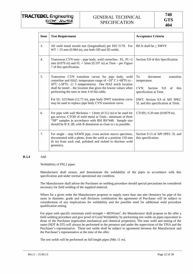
GENERAL TECHNICALSPECIFICATION
740GTS404
Rev.5 – 21.06.13 Page 22 of 38
Item Test Requirement Acceptance Criteria
3. All weld metal tensile test (longitudinal) per ISO 5178. ForWT > 25 mm (0.984 in), test both OD and ID welds.
R0.5t shall be > SMYS
4. Transverse CVN tests – pipe body, weld centerline. FL, FL+2mm (0.079 in) and FL + 5mm (0.197 in) at Ttest – per Figure7 of this specification.
Section 9.8 of this Specification
5. Transverse CVN transition curves for pipe body, weldcenterline and HAZ; temperature range of +200 C (+68oF) to -500C (-58oF) ( 5 temperatures). One HAZ notch locationshall be tested – the location that gives the lowest values whenperforming the tests in item 4 of this table.
For D> 323.9mm (12.75 in), pipe body DWT transition curvemay be used to replace pipe body CVN transition curve.
To document transitiontemperature.
CVN: Section 9.8 of thisspecification at Ttest.
DWT: Section 9.9 of API SPEC5L and this specification at Tmin.
6. For pipe with wall thickness > 13mm (0.512 in) to be used forgas service, CTOD of weld metal at Tmin.- minimum of three“NP” samples in accordance with BSI BS7448. Sample sizeshould be B X 2B, with B dimension as close to t as possible.
CTOD> 0.20 mm (0.0079 in).
7. For single – step SAWH pipe, cross section macro specimen,documented with a photo, from the weld at a position 150 mm(6 in) from each end, polished and etched to disclose weldgeometry.
Section 9.13 of API SPEC 5L andthis specification.
B.5.4 Add
Weldability of PSL2 pipes
Manufacturer shall ensure, and demonstrate the weldability of the pipes in accordance with thisspecification and under normal operational site condition.
The Manufacturer shall advise the Purchaser on welding procedure should special precautions be considerednecessary for field welding of the supplied material.
Where for a given order the Manufacturer proposes to supply more than one aim chemistry for pipe of thesame in diameter, grade and wall thickness combination the agreement of Purchaser will be subject toconsideration of any implications for weldability and the possible need for additional weld procedurequalification testing.
For pipes with specific minimum yield strength > 485N/mm2, the Manufacturer shall propose in the offer afield welding procedure and give proof of Good Weldability by performing test welds on pipes equivalent tothose of the Purchaser (equivalent mechanical and chemical properties). The tests weld and testing of thesame (NDT & DT) will always be performed in the presence and under the supervision of the TPIA and thePurchaser’s representative. These test welds shall be subject to agreement between the Manufacturer andthe Purchaser’s representative at the time of the offer.
The test welds will be performed on full length pipes (Min 11 m).

GENERAL TECHNICALSPECIFICATION
740GTS404
Rev.5 – 21.06.13 Page 23 of 38
B.6 INSPECTION AND TEST PLAN (ITP) (ADDED)
Prior to commencement of any production work, the Manufacturer shall submit a job-specific ITP forPurchaser review and approval. The ITP format shall include the following (refer also to Annex Q):
1. The complete sequence of operations shall be submitted for approval to the Third Party inspectionAgency and the Purchaser,
2. The specific activity and associated procedure or specification reference governing the activity.
3. Acceptance criteria.
4. Responsible organization performing the activity.
5. Verifying document to be used for recording inspection and test results.
6. Manufacturer shall show designated monitor, witness or hold points in manufacturing process.
7. Provisions for Purchaser to designate third party monitor, witness and hold points,
8. Purchaser participation for each activity to be completed by Purchaser.
9. The designated responsible (Purchaser representative) for witness or hold points has to be notified 2weeks in advance by the Manufacturer,
10. The designated responsible of Purchaser present during manufacturing of pipes must have full access tothe manufacturing sites and will determine on daily base the inspection points he plan to attend.
B.7 FIRST DAY PRODUCTION (ADDED)
First day production shall be sampled and inspected to cover each size, thickness and heat. [In case ofmultiple heat nos., at least 3 (three) heats shall be covered]. All the tests of approved QAP are applicable tofirst day production test moreover weldability test is also included.
The tried and internationally accepted welding consumables are to be used and vendor has to submit recordof these tests prior to start of first day production test.
All weld tensile tests shall be carried out as per ASME Section IIC to ensure the properties of weldingconsumables.

GENERAL TECHNICALSPECIFICATION
740GTS404
Rev.5 – 21.06.13 Page 24 of 38
Annex C
(normative)
Treatment of Surface imperfections and defects
C.4. REPAIR OF DEFECTS BY WELDING
C.4.2 Repairs to the weld shall only be performed prior to cold expansion and hydrostatic testing. Repairs on pipeshall be made using a Purchaser approved WPS. The following restrictions also apply;
a) Repair welding shall be executed only after specific approval of Purchaser,
b) No through thickness repair,
c) An interruption of a SAW welding is not considered as a repair unless unacceptable defects are found
d) No back-to-back repair,
e) Maximum of 3 weld seam repairs per pipe length are allowed,
f) Repair welding of crack is not allowed,
g) Repair of a repair shall not be allowed,
h) Manual metal-arc repairs shall not be completed in a single pass a minimum of 2 passes is required,
i) In case of SMAW (Shield Metal Arc Welding) weld repair only low hydrogen electrodes shall be used
j) If carbon arc gouging is used for defect removal, at least 3.2 mm additional metal shall be removed bychipping or grinding to completely remove any carburized area prior to making the repair weld,
k) Minimum length between weld repairs shall be not less 100 mm or one pipe diameter whichever ishigher,
l) No weld repair within 300 mm or one diameter (whichever is higher) of pipe end,
m) The maximum length of any repair shall be 300 mm,
n) The properties of the weld repair shall meet the specification requirements for the longitudinal / helicalseam weld,
C.4.3 The total length of repaired zones on each pipe shall be < 3 % of total length of weld.
C4.6 The complete removal of defects prior to weld repair shall be verified by magnetic particle or liquidpenetrant methods. The total area of the weld repair shall be inspected by ultrasonic and radiographicmethods to the acceptance levels of this specification. Radiographic film exposure shall extend at least 100mm beyond each end of the weld repair.
C4.7 Repair of defects by welding
Arc stops during welding shall be repaired according to the qualified weld repair procedure.
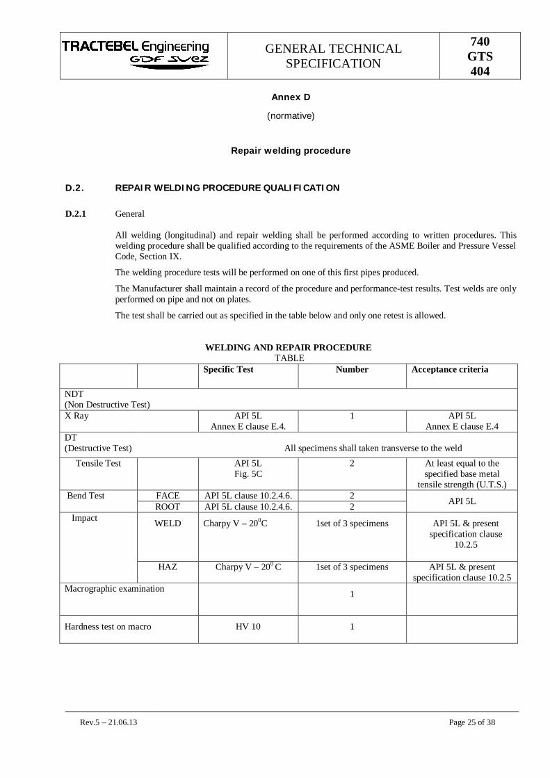
GENERAL TECHNICALSPECIFICATION
740GTS404
Rev.5 – 21.06.13 Page 25 of 38
Annex D
(normative)
Repair welding procedure
D.2. REPAIR WELDING PROCEDURE QUALIFICATION
D.2.1 General
All welding (longitudinal) and repair welding shall be performed according to written procedures. Thiswelding procedure shall be qualified according to the requirements of the ASME Boiler and Pressure VesselCode, Section IX.
The welding procedure tests will be performed on one of this first pipes produced.
The Manufacturer shall maintain a record of the procedure and performance-test results. Test welds are onlyperformed on pipe and not on plates.
The test shall be carried out as specified in the table below and only one retest is allowed.
WELDING AND REPAIR PROCEDURE TABLE
Specific Test Number Acceptance criteria
NDT(Non Destructive Test)X Ray API 5L
Annex E clause E.4.1 API 5L
Annex E clause E.4DT(Destructive Test) All specimens shall taken transverse to the weld
Tensile Test API 5LFig. 5C
2 At least equal to thespecified base metal
tensile strength (U.T.S.)Bend Test FACE API 5L clause 10.2.4.6. 2 API 5LROOT API 5L clause 10.2.4.6. 2Impact WELD Charpy V – 200C 1set of 3 specimens API 5L & present
specification clause10.2.5
HAZ Charpy V – 200 C 1set of 3 specimens API 5L & presentspecification clause 10.2.5
Macrographic examination 1
Hardness test on macro HV 10 1

GENERAL TECHNICALSPECIFICATION
740GTS404
Rev.5 – 21.06.13 Page 26 of 38
Micrographic examination: the etched surface of the macro test specimen viewed macroscopically mustdisplay the image of a well performed welded joint with sufficient penetration free from linear defects andimportant inclusions. In case of doubt the etched surface must be examined microscopically and additionalmacroscopically examinations of other areas may be required.
The hardness will not exceed the values measured in the parent metal by more than: 80 points for the weldand 100 points for the HAZ with an absolute maximum value in informity with clause 9.3.3 of the presentspecification.
The instrument used for the hardness test has to be specified by the Manufacturer and submitted forapproval by the third party inspection agency.

GENERAL TECHNICALSPECIFICATION
740GTS404
Rev.5 – 21.06.13 Page 27 of 38
Annex E
(normative)
Non-destructive inspection for other than sour service or offshore service
E.1 QUALIFICATION OF PERSONNEL
Final non-destructive inspection shall be performed by level 2 or 3 personnel. All level 2 personnel shall bequalified and certified for the specific NDT method by a Certification Body or Level 3 in accordance withBSI BS EN 473 or the ASNT CP 189 or Purchaser approved equivalent. A current list of qualified NDTpersonnel is to be presented to Purchaser prior to using the personnel.
For Ultrasonic Testing, at least one level 3 qualified inspectors shall be available full time to the mill foroverall supervision. A level 2 inspector is required for shift supervision, manual weld inspection andcalibration of all systems (both manual and automated).
For all items order the entire provision of Annex shall apply.
E.2 STANDARD PRACTICE FOR INSPECTION
Ultrasonic equipment, electronic signal suppression and damping shall not be used during calibration,sensitivity checking or scanning.
All final automatic UT equipment shall incorporate a fully automatic monitoring and recording system toindicate the location of unacceptable imperfections and loss of coupling that encompasses an area greaterthan the allowable imperfection size. Alarms, lack of coupling or signal transmission shall be accompaniedby an audible alarm, and automatic or manual paint systems so that areas of the pipe that have valid alarmsdue to an imperfection and / or loss of coupling are clearly indicated on the pipe.
Probe shoe or wear face surfaces shall have their radius conform to the diameter of the pipe surface, or theshape of the weld bead, to ensure intimate contact between the surface to be inspected and the transducerwear face.
E.2.1 AUTOMATIC STRAIGHT BEAM UT INSPECTION (ADDED)
Through – transmission type probe systems should not be used for lamination detection.
For lamination detection, probes should be dual element with element size as per ISO 10124 or ISO 12094.
For detection of laminar imperfections by manual and automatic systems, initially, the signal height formthe backwall in the reference standard should be set from 60% to 90% of Full Screen Height (FSH).Reference to the backwall is necessary to verify signal perpendicularity and sound coupling duringscanning. The gain should then be increased to set the signal from the respective edge or body reflector at100% FSH. Automatic equipment shall have a minimum of two independent gates so that the flaw gateshall be set with positive logic (> 50% FSH), and the backwall gate shall be set with negative logic (> 20%of FSH). Loss of backwall – defined as backwall signal height < 20% FSH – greater in size than anacceptable imperfection shall be regarded as a rejectable condition. Indications greater than primaryreference level in the flaw gate are rejectable even if there is no loss of backwall.
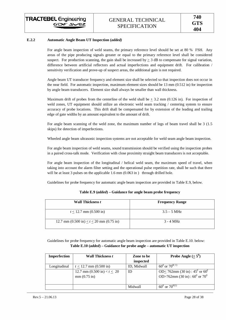
GENERAL TECHNICALSPECIFICATION
740GTS404
Rev.5 – 21.06.13 Page 28 of 38
E.2.2 Automatic Angle Beam UT Inspection (added)
For angle beam inspection of weld seams, the primary reference level should be set at 80 % FSH. Anyareas of the pipe producing signals greater or equal to the primary reference level shall be consideredsuspect. For production scanning, the gain shall be increased by > 3 dB to compensate for signal variation,difference between artificial reflectors and actual imperfections and equipment drift. For calibration /sensitivity verification and prove-up of suspect areas, the additional gain is not required.
Angle beam UT transducer frequency and element size shall be selected so that inspection does not occur inthe near field. For automatic inspection, maximum element sizes should be 13 mm (0.512 in) for inspectionby angle beam transducers. Element size shall always be smaller than wall thickness.
Maximum drift of probes from the centerline of the weld shall be + 3.2 mm (0.126 in). For inspection ofweld zones, UT equipment should utilize an electronic weld seam tracking / centering system to ensureaccuracy of probe locations. This drift shall be compensated for by extension of the leading and trailingedge of gate widths by an amount equivalent to the amount of drift.
For angle beam scanning of the weld zone, the maximum number of legs of beam travel shall be 3 (1.5skips) for detection of imperfections.
Wheeled angle beam ultrasonic inspection systems are not acceptable for weld seam angle beam inspection.
For angle beam inspection of weld seams, sound transmission should be verified using the inspection probesin a paired cross-talk mode. Verification with close proximity straight beam transducers is not acceptable.
For angle beam inspection of the longitudinal / helical weld seam, the maximum speed of travel, whentaking into account the alarm filter setting and the operational pulse repetition rate, shall be such that therewill be at least 3 pulses on the applicable 1.6 mm (0.063 in ) through drilled hole.
Guidelines for probe frequency for automatic angle beam inspection are provided in Table E.9, below.
Table E.9 (added) – Guidance for angle beam probe frequency
Wall Thickness t Frequency Range
t < 12.7 mm (0.500 in) 3.5 – 5 MHz
12.7 mm (0.500 in) < t < 20 mm (0.75 in) 3 - 4 MHz
Guidelines for probe frequency for automatic angle beam inspection are provided in Table E.10. below:Table E.10 (added) – Guidance for probe angle – automatic UT inspection
Imperfection Wall Thickness t Zone to beinspected
Probe Angle (+ 50)
Longitudinal t < 12.7 mm (0.500 in) ID, Midwall 600 or 700( 1)
12.7 mm (0.500 in) < t < 20mm (0.75 in)
ID OD< 762mm (30 in) : 450 or 600
OD>762mm (30 in) : 600 or 700
Midwall 600 or 700(1)
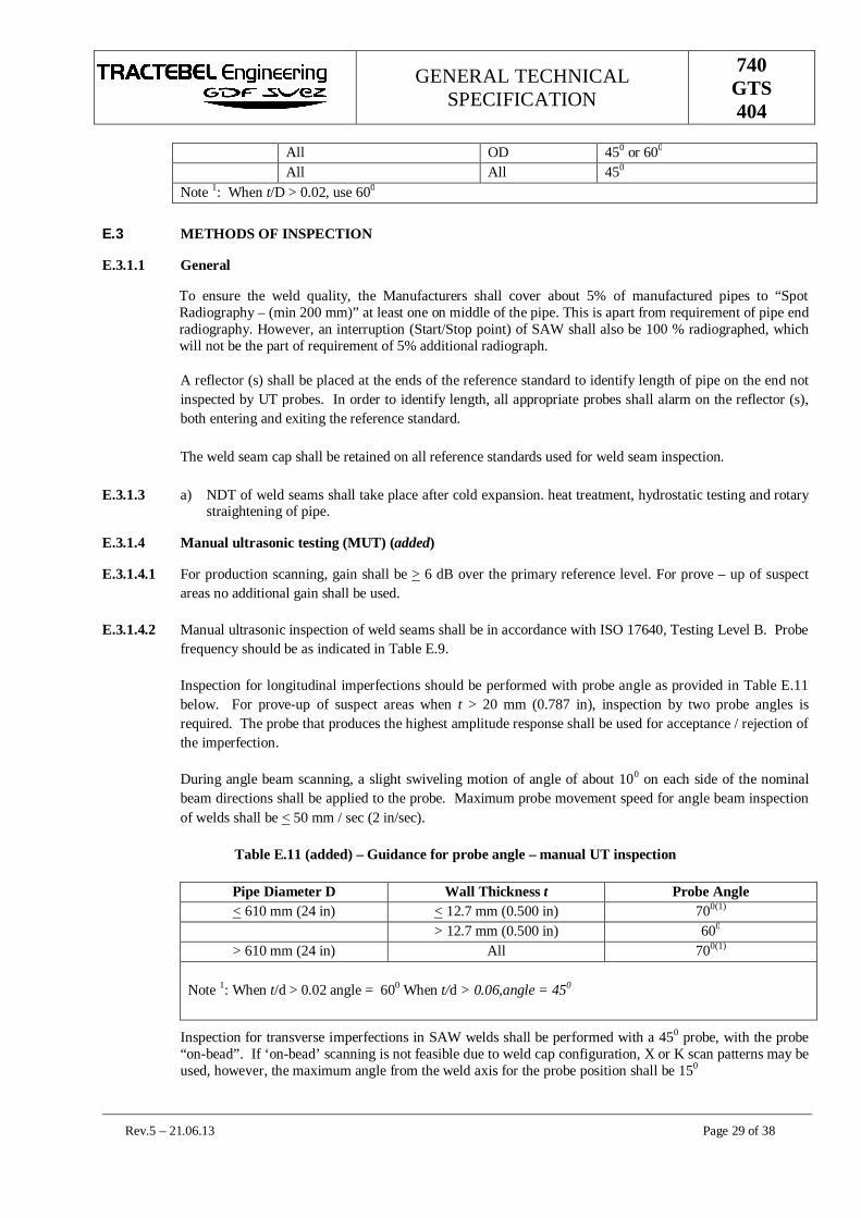
GENERAL TECHNICALSPECIFICATION
740GTS404
Rev.5 – 21.06.13 Page 29 of 38
All OD 450 or 600
All All 450
Note 1: When t/D > 0.02, use 600
E.3 METHODS OF INSPECTION
E.3.1.1 General
To ensure the weld quality, the Manufacturers shall cover about 5% of manufactured pipes to “SpotRadiography – (min 200 mm)” at least one on middle of the pipe. This is apart from requirement of pipe endradiography. However, an interruption (Start/Stop point) of SAW shall also be 100 % radiographed, whichwill not be the part of requirement of 5% additional radiograph.
A reflector (s) shall be placed at the ends of the reference standard to identify length of pipe on the end notinspected by UT probes. In order to identify length, all appropriate probes shall alarm on the reflector (s),both entering and exiting the reference standard.
The weld seam cap shall be retained on all reference standards used for weld seam inspection.
E.3.1.3 a) NDT of weld seams shall take place after cold expansion. heat treatment, hydrostatic testing and rotarystraightening of pipe.
E.3.1.4 Manual ultrasonic testing (MUT) (added)
E.3.1.4.1 For production scanning, gain shall be > 6 dB over the primary reference level. For prove – up of suspectareas no additional gain shall be used.
E.3.1.4.2 Manual ultrasonic inspection of weld seams shall be in accordance with ISO 17640, Testing Level B. Probefrequency should be as indicated in Table E.9.
Inspection for longitudinal imperfections should be performed with probe angle as provided in Table E.11below. For prove-up of suspect areas when t > 20 mm (0.787 in), inspection by two probe angles isrequired. The probe that produces the highest amplitude response shall be used for acceptance / rejection ofthe imperfection.
During angle beam scanning, a slight swiveling motion of angle of about 100 on each side of the nominalbeam directions shall be applied to the probe. Maximum probe movement speed for angle beam inspectionof welds shall be < 50 mm / sec (2 in/sec).
Table E.11 (added) – Guidance for probe angle – manual UT inspection
Pipe Diameter D Wall Thickness t Probe Angle< 610 mm (24 in) < 12.7 mm (0.500 in) 700(1)
> 12.7 mm (0.500 in) 600
> 610 mm (24 in) All 700(1)
Note 1: When t/d > 0.02 angle = 600 When t/d > 0.06,angle = 450
Inspection for transverse imperfections in SAW welds shall be performed with a 450 probe, with the probe“on-bead”. If ‘on-bead’ scanning is not feasible due to weld cap configuration, X or K scan patterns may beused, however, the maximum angle from the weld axis for the probe position shall be 150
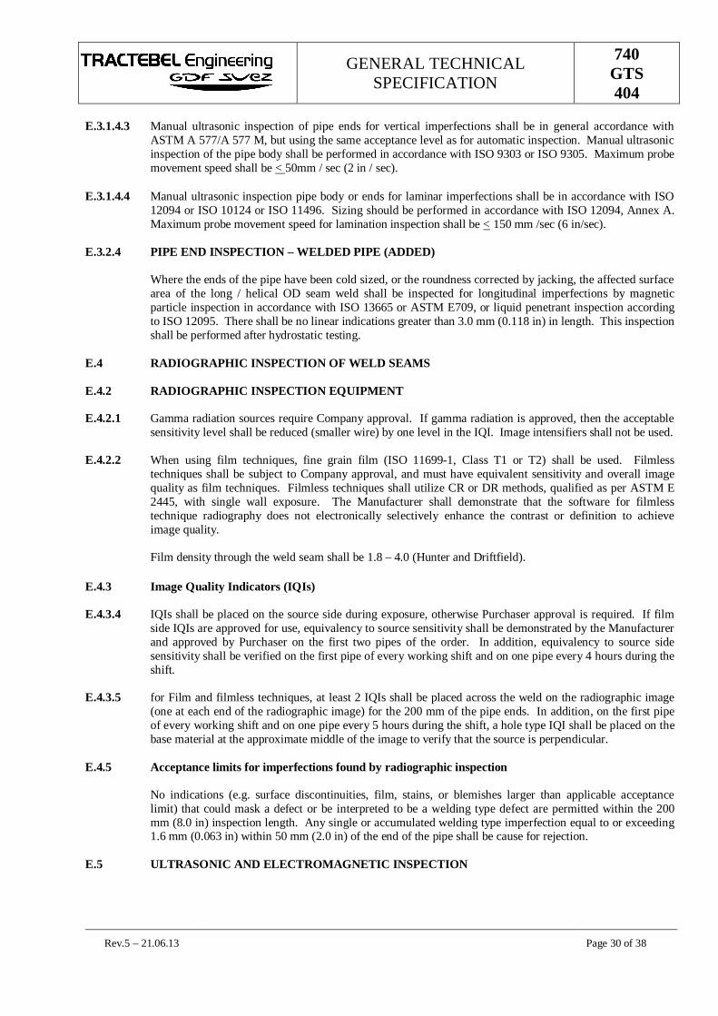
GENERAL TECHNICALSPECIFICATION
740GTS404
Rev.5 – 21.06.13 Page 30 of 38
E.3.1.4.3 Manual ultrasonic inspection of pipe ends for vertical imperfections shall be in general accordance withASTM A 577/A 577 M, but using the same acceptance level as for automatic inspection. Manual ultrasonicinspection of the pipe body shall be performed in accordance with ISO 9303 or ISO 9305. Maximum probemovement speed shall be < 50mm / sec (2 in / sec).
E.3.1.4.4 Manual ultrasonic inspection pipe body or ends for laminar imperfections shall be in accordance with ISO12094 or ISO 10124 or ISO 11496. Sizing should be performed in accordance with ISO 12094, Annex A.Maximum probe movement speed for lamination inspection shall be < 150 mm /sec (6 in/sec).
E.3.2.4 PIPE END INSPECTION – WELDED PIPE (ADDED)
Where the ends of the pipe have been cold sized, or the roundness corrected by jacking, the affected surfacearea of the long / helical OD seam weld shall be inspected for longitudinal imperfections by magneticparticle inspection in accordance with ISO 13665 or ASTM E709, or liquid penetrant inspection accordingto ISO 12095. There shall be no linear indications greater than 3.0 mm (0.118 in) in length. This inspectionshall be performed after hydrostatic testing.
E.4 RADIOGRAPHIC INSPECTION OF WELD SEAMS
E.4.2 RADIOGRAPHIC INSPECTION EQUIPMENT
E.4.2.1 Gamma radiation sources require Company approval. If gamma radiation is approved, then the acceptablesensitivity level shall be reduced (smaller wire) by one level in the IQI. Image intensifiers shall not be used.
E.4.2.2 When using film techniques, fine grain film (ISO 11699-1, Class T1 or T2) shall be used. Filmlesstechniques shall be subject to Company approval, and must have equivalent sensitivity and overall imagequality as film techniques. Filmless techniques shall utilize CR or DR methods, qualified as per ASTM E2445, with single wall exposure. The Manufacturer shall demonstrate that the software for filmlesstechnique radiography does not electronically selectively enhance the contrast or definition to achieveimage quality.
Film density through the weld seam shall be 1.8 – 4.0 (Hunter and Driftfield).
E.4.3 Image Quality Indicators (IQIs)
E.4.3.4 IQIs shall be placed on the source side during exposure, otherwise Purchaser approval is required. If filmside IQIs are approved for use, equivalency to source sensitivity shall be demonstrated by the Manufacturerand approved by Purchaser on the first two pipes of the order. In addition, equivalency to source sidesensitivity shall be verified on the first pipe of every working shift and on one pipe every 4 hours during theshift.
E.4.3.5 for Film and filmless techniques, at least 2 IQIs shall be placed across the weld on the radiographic image(one at each end of the radiographic image) for the 200 mm of the pipe ends. In addition, on the first pipeof every working shift and on one pipe every 5 hours during the shift, a hole type IQI shall be placed on thebase material at the approximate middle of the image to verify that the source is perpendicular.
E.4.5 Acceptance limits for imperfections found by radiographic inspection
No indications (e.g. surface discontinuities, film, stains, or blemishes larger than applicable acceptancelimit) that could mask a defect or be interpreted to be a welding type defect are permitted within the 200mm (8.0 in) inspection length. Any single or accumulated welding type imperfection equal to or exceeding1.6 mm (0.063 in) within 50 mm (2.0 in) of the end of the pipe shall be cause for rejection.
E.5 ULTRASONIC AND ELECTROMAGNETIC INSPECTION

GENERAL TECHNICALSPECIFICATION
740GTS404
Rev.5 – 21.06.13 Page 31 of 38
E.5.3 Ultrasonic and electromagnetic inspection references standards
E.5.2.3 Add
NDT Reference Standards
Clause E.5.2.3 of API 5L is complemented as follow:
If the “notches” method is selected, the reference notch shall have a depth of 5 % ( ± 15 %) with aminimum of 0,012 in ± 0,002 in (0,3 mm ± 0,05 mm) except, that the “V” notch type may be used, atdiscretion of the Manufacturer, when the notch depth is less than or equal to 2/100 in. (0.5 mm) ormaximum 5% t whichever is the smallest.
If the “holes” method is selected, the radially drilled hole shall have a diameter of 1/16 in (1.6 mm).
E.5.3 Instrument Standardization
All UT sensitivity checks shall be performed dynamically at the same or greater speed as that used forproduction scanning. Sensitivity checks shall be performed at the gain setting as used for productioninspection. The sensitivity check is successful if all appropriate channels alarms, within the gate, on therequired target reflector in the reference standard – without any alteration of any setting. All sensitivitychecks are independent of each other.
The 3 dB allowance in Paragraph 8.5 in ISO 9765 and Paragraph 7.5 in ISO 10124, ISO 12094 and ISO13663 shall not be allowed for digital equipment.
E.5.5.2 Acceptance limits
Suspect areas shall be accepted / rejected using the same NDT method employed to find the originalimperfection, except as allowed in c).
a) Radiography approval of ultrasonic indications that exceed the applicable acceptance limit in TableE.8, “ Acceptance Limit,” of API SPEC 5L is allowed provided the indication is confirmed to be a slag-inclusion or gas-pocket that meets the requirements of API SPEC 5L Tables E.5, “Elongated Slag-Inclusion–Type Imperfections,” and / or Table E.6, “Circular Slag – Inclusion-Type and Gas-Pocket-Typeimperfections. “RT shall meet the requirements of Sections E.4.2 and E4.3 of this specification. Cracks,lack of fusion, incomplete penetration and UT indications with radiographic images that display noimperfections shall be classified as defects.
E.5.7 Weld Repair
Real time radiography (fluoroscopic) inspection of weld repairs is not allowed.
E.6 MAGNETIC PARTICLE INSPECTION
E.6.2 Equipment
Magnetic particle testing shall be performed with active (continuous) field, unless otherwise approved byCompany. (Field strength shall not be verified with pie field indicators – pie field indicators may be used toidentify field direction).
Electromagnetic AC yokes shall have a minimum lifting force of 5 kg at maximum leg spread. Verificationis required at the start of each operating shift.
Permanent magnets shall not be used. DC yokes require Purchaser approval.
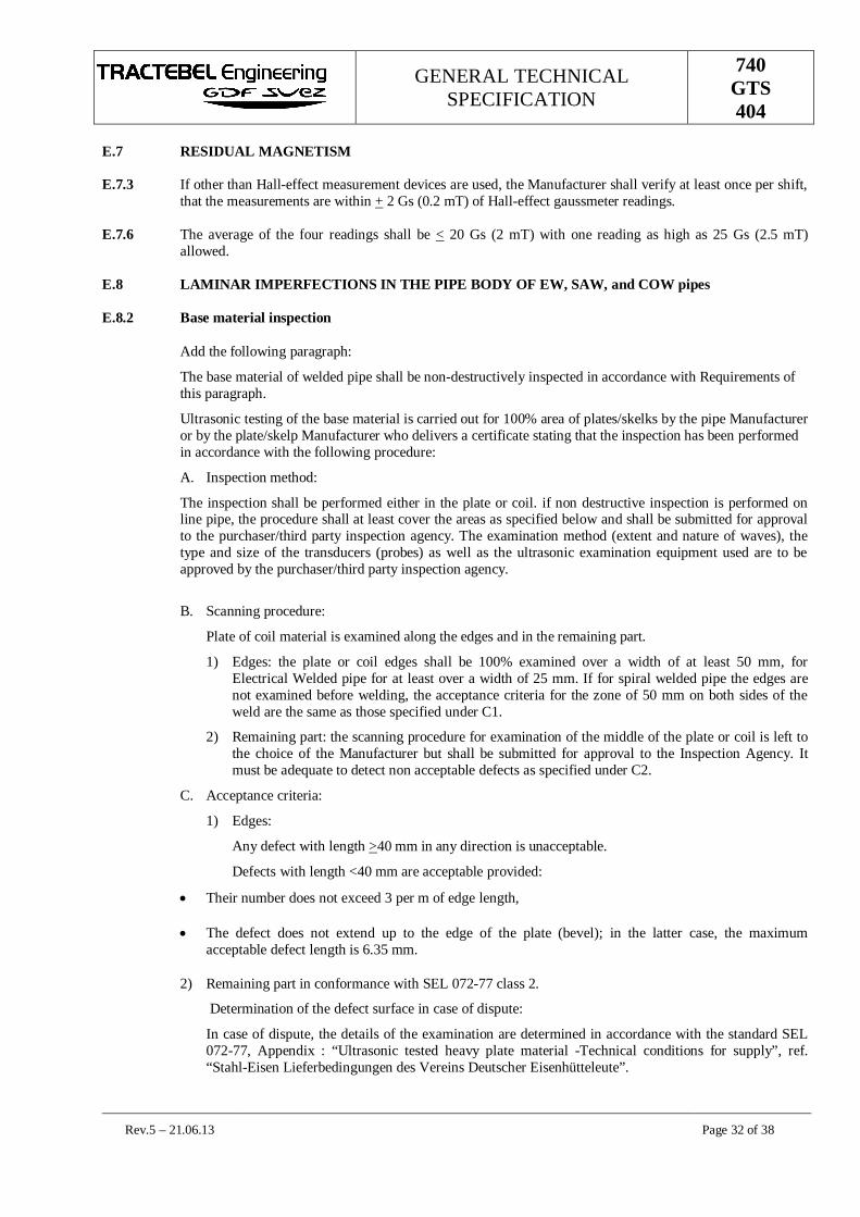
GENERAL TECHNICALSPECIFICATION
740GTS404
Rev.5 – 21.06.13 Page 32 of 38
E.7 RESIDUAL MAGNETISM
E.7.3 If other than Hall-effect measurement devices are used, the Manufacturer shall verify at least once per shift,that the measurements are within + 2 Gs (0.2 mT) of Hall-effect gaussmeter readings.
E.7.6 The average of the four readings shall be < 20 Gs (2 mT) with one reading as high as 25 Gs (2.5 mT)allowed.
E.8 LAMINAR IMPERFECTIONS IN THE PIPE BODY OF EW, SAW, and COW pipes
E.8.2 Base material inspection
Add the following paragraph:
The base material of welded pipe shall be non-destructively inspected in accordance with Requirements ofthis paragraph.
Ultrasonic testing of the base material is carried out for 100% area of plates/skelks by the pipe Manufactureror by the plate/skelp Manufacturer who delivers a certificate stating that the inspection has been performedin accordance with the following procedure:
A. Inspection method:
The inspection shall be performed either in the plate or coil. if non destructive inspection is performed online pipe, the procedure shall at least cover the areas as specified below and shall be submitted for approvalto the purchaser/third party inspection agency. The examination method (extent and nature of waves), thetype and size of the transducers (probes) as well as the ultrasonic examination equipment used are to beapproved by the purchaser/third party inspection agency.
B. Scanning procedure:
Plate of coil material is examined along the edges and in the remaining part.
1) Edges: the plate or coil edges shall be 100% examined over a width of at least 50 mm, forElectrical Welded pipe for at least over a width of 25 mm. If for spiral welded pipe the edges arenot examined before welding, the acceptance criteria for the zone of 50 mm on both sides of theweld are the same as those specified under C1.
2) Remaining part: the scanning procedure for examination of the middle of the plate or coil is left tothe choice of the Manufacturer but shall be submitted for approval to the Inspection Agency. Itmust be adequate to detect non acceptable defects as specified under C2.
C. Acceptance criteria:
1) Edges:
Any defect with length >40 mm in any direction is unacceptable.
Defects with length <40 mm are acceptable provided:
Their number does not exceed 3 per m of edge length,
The defect does not extend up to the edge of the plate (bevel); in the latter case, the maximumacceptable defect length is 6.35 mm.
2) Remaining part in conformance with SEL 072-77 class 2.
Determination of the defect surface in case of dispute:
In case of dispute, the details of the examination are determined in accordance with the standard SEL072-77, Appendix : “Ultrasonic tested heavy plate material -Technical conditions for supply”, ref.“Stahl-Eisen Lieferbedingungen des Vereins Deutscher Eisenhütteleute”.
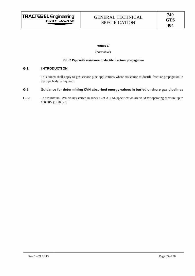
GENERAL TECHNICALSPECIFICATION
740GTS404
Rev.5 – 21.06.13 Page 33 of 38
Annex G
(normative)
PSL 2 Pipe with resistance to ductile fracture propagation
G.1 INTRODUCTION
This annex shall apply to gas service pipe applications where resistance to ductile fracture propagation inthe pipe body is required.
G.6 Guidance for determining CVN absorbed energy values in buried onshore gas pipelines
G.6.1 The minimum CVN values started in annex G of API 5L specification are valid for operating pressure up to100 HPa (1450 psi).

GENERAL TECHNICALSPECIFICATION
740GTS404
Rev.5 – 21.06.13 Page 34 of 38
Annex J
(normative)
PSL 2 Pipe Ordered for offshore service
J.1 INTRODUCTION
Although this annex in API SPEC 5L is for offshore line pipe applications, certain clauses of Annex J ofAPI SPEC 5L are required by this specification for onshore pipe – these requirements are noted in the mainbody of this specification.
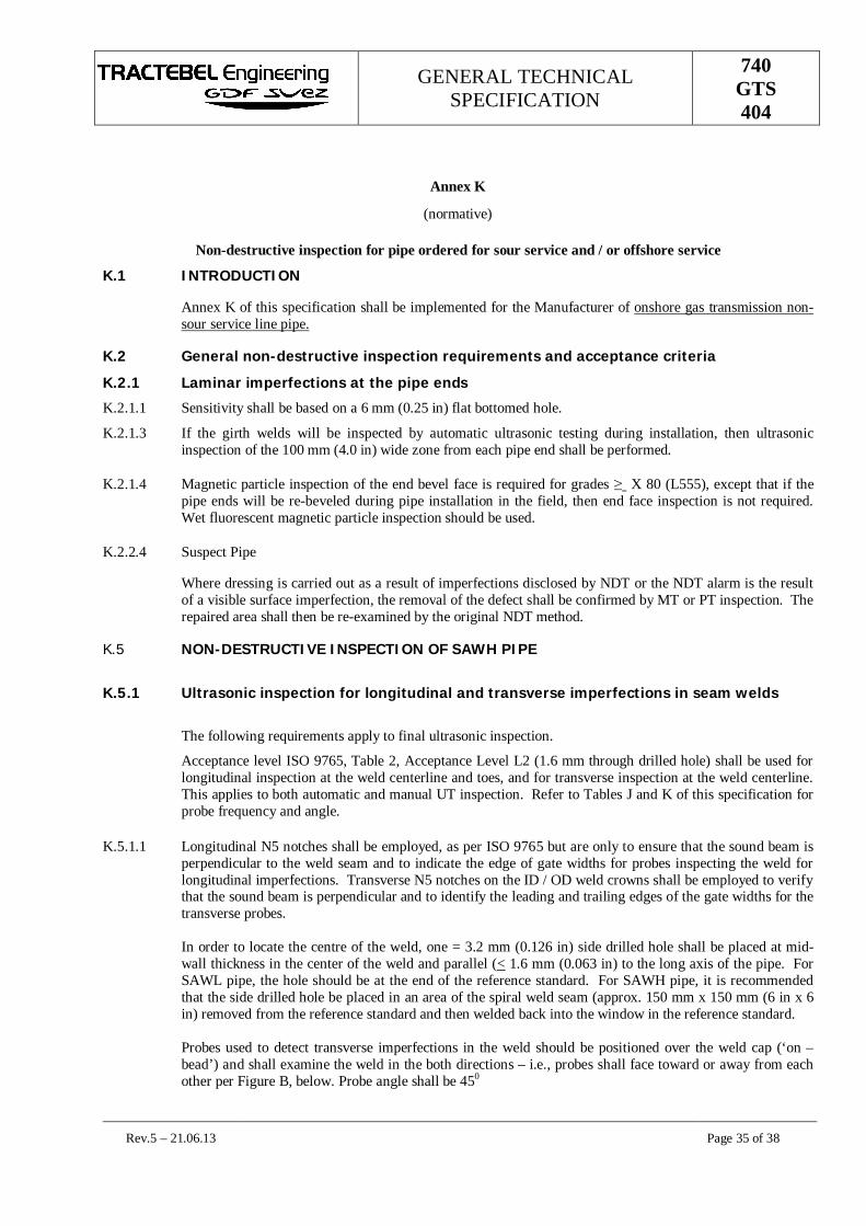
GENERAL TECHNICALSPECIFICATION
740GTS404
Rev.5 – 21.06.13 Page 35 of 38
Annex K
(normative)
Non-destructive inspection for pipe ordered for sour service and / or offshore service
K.1 INTRODUCTION
Annex K of this specification shall be implemented for the Manufacturer of onshore gas transmission non-sour service line pipe.
K.2 General non-destructive inspection requirements and acceptance criteria
K.2.1 Laminar imperfections at the pipe ends
K.2.1.1 Sensitivity shall be based on a 6 mm (0.25 in) flat bottomed hole.
K.2.1.3 If the girth welds will be inspected by automatic ultrasonic testing during installation, then ultrasonicinspection of the 100 mm (4.0 in) wide zone from each pipe end shall be performed.
K.2.1.4 Magnetic particle inspection of the end bevel face is required for grades X 80 (L555), except that if thepipe ends will be re-beveled during pipe installation in the field, then end face inspection is not required.Wet fluorescent magnetic particle inspection should be used.
K.2.2.4 Suspect Pipe
Where dressing is carried out as a result of imperfections disclosed by NDT or the NDT alarm is the resultof a visible surface imperfection, the removal of the defect shall be confirmed by MT or PT inspection. Therepaired area shall then be re-examined by the original NDT method.
K.5 NON-DESTRUCTIVE INSPECTION OF SAWH PIPE
K.5.1 Ultrasonic inspection for longitudinal and transverse imperfections in seam welds
The following requirements apply to final ultrasonic inspection.
Acceptance level ISO 9765, Table 2, Acceptance Level L2 (1.6 mm through drilled hole) shall be used forlongitudinal inspection at the weld centerline and toes, and for transverse inspection at the weld centerline.This applies to both automatic and manual UT inspection. Refer to Tables J and K of this specification forprobe frequency and angle.
K.5.1.1 Longitudinal N5 notches shall be employed, as per ISO 9765 but are only to ensure that the sound beam isperpendicular to the weld seam and to indicate the edge of gate widths for probes inspecting the weld forlongitudinal imperfections. Transverse N5 notches on the ID / OD weld crowns shall be employed to verifythat the sound beam is perpendicular and to identify the leading and trailing edges of the gate widths for thetransverse probes.
In order to locate the centre of the weld, one = 3.2 mm (0.126 in) side drilled hole shall be placed at mid-wall thickness in the center of the weld and parallel (< 1.6 mm (0.063 in) to the long axis of the pipe. ForSAWL pipe, the hole should be at the end of the reference standard. For SAWH pipe, it is recommendedthat the side drilled hole be placed in an area of the spiral weld seam (approx. 150 mm x 150 mm (6 in x 6in) removed from the reference standard and then welded back into the window in the reference standard.
Probes used to detect transverse imperfections in the weld should be positioned over the weld cap (‘on –bead’) and shall examine the weld in the both directions – i.e., probes shall face toward or away from eachother per Figure B, below. Probe angle shall be 450
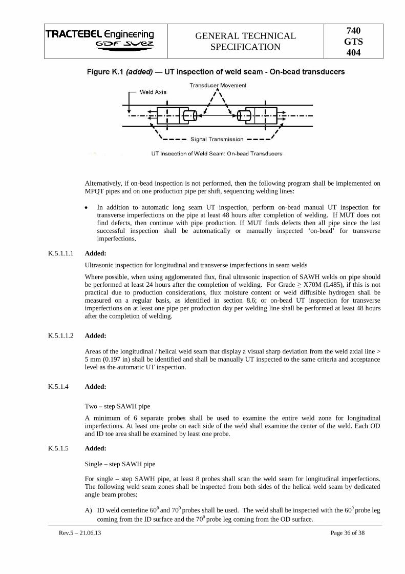
GENERAL TECHNICALSPECIFICATION
740GTS404
Rev.5 – 21.06.13 Page 36 of 38
Alternatively, if on-bead inspection is not performed, then the following program shall be implemented onMPQT pipes and on one production pipe per shift, sequencing welding lines:
In addition to automatic long seam UT inspection, perform on-bead manual UT inspection fortransverse imperfections on the pipe at least 48 hours after completion of welding. If MUT does notfind defects, then continue with pipe production. If MUT finds defects then all pipe since the lastsuccessful inspection shall be automatically or manually inspected ‘on-bead’ for transverseimperfections.
K.5.1.1.1 Added:
Ultrasonic inspection for longitudinal and transverse imperfections in seam welds
Where possible, when using agglomerated flux, final ultrasonic inspection of SAWH welds on pipe shouldbe performed at least 24 hours after the completion of welding. For Grade X70M (L485), if this is notpractical due to production considerations, flux moisture content or weld diffusible hydrogen shall bemeasured on a regular basis, as identified in section 8.6; or on-bead UT inspection for transverseimperfections on at least one pipe per production day per welding line shall be performed at least 48 hoursafter the completion of welding.
K.5.1.1.2 Added:
Areas of the longitudinal / helical weld seam that display a visual sharp deviation from the weld axial line >5 mm (0.197 in) shall be identified and shall be manually UT inspected to the same criteria and acceptancelevel as the automatic UT inspection.
K.5.1.4 Added:
Two – step SAWH pipe
A minimum of 6 separate probes shall be used to examine the entire weld zone for longitudinalimperfections. At least one probe on each side of the weld shall examine the center of the weld. Each ODand ID toe area shall be examined by least one probe.
K.5.1.5 Added:
Single – step SAWH pipe
For single – step SAWH pipe, at least 8 probes shall scan the weld seam for longitudinal imperfections.The following weld seam zones shall be inspected from both sides of the helical weld seam by dedicatedangle beam probes:
A) ID weld centerline 600 and 700 probes shall be used. The weld shall be inspected with the 600 probe legcoming from the ID surface and the 700 probe leg coming from the OD surface.

GENERAL TECHNICALSPECIFICATION
740GTS404
Rev.5 – 21.06.13 Page 37 of 38
B) ID and OD weld toe areas to the approximate center of the respective weld. For pipe wall thickness <12.7 mm (0.500 in), the probe angle should be 700. For pipe wall thickness > 12.7 mm, the probe angleshould be 600. There shall be at least one probe aiming at each toe-to-centerline area for a total of 4probes.
In addition, for single-step SAWH pipe mills without automatic seam tracking/gap control for welding,there shall be probes focusing on the difference in circumferential distance between the OD weld toe signaland the ID weld toe signal. This difference shall be set to ensure that weld seam misalignment does notexceed the maximum identified in API SPEC 5L Section 9.13.3, “Misalignment of the Weld beads of SAWand COW pipes.”
K.5.2 Laminar imperfections in the pipe body and on the strip/coil edges
K.5.2.1 Ultrasonic inspection shall be used to verify that the skelp/pipe body is free of laminar imperfections greaterthan those permitted by Table K.1, Acceptance Criteria for Laminar imperfections, “for “Sour” service. Forpipe grades > X60 (L415), coverage during inspection shall be 100% of the skelp/pipe surface.
K.5.2.2 The longitudinal strip/plate edges shall be ultrasonically inspected over a width of at least 50 mm (2.0 in).Sensitivity shall be based on a 6 mm (0.25 in) flat bottomed hole. Acceptance limits shall be as perstandard “Sour” service condition in Table K. 1 of API SPEC 5L.
K.5.3 Non – destructive inspection of the weld seam at the pipe ends / repaired areas
The weld seam not inspected (dead zone) by the automatic UT inspection system at the pipe ends shall beinspected by UT methods for longitudinal and transverse imperfections to the same acceptance level as forautomatic inspection.

GENERAL TECHNICALSPECIFICATION
740GTS404
Rev.5 – 21.06.13 Page 38 of 38
Annex Q
(normative)
Purchaser Indicative Inspection and Quality Plan

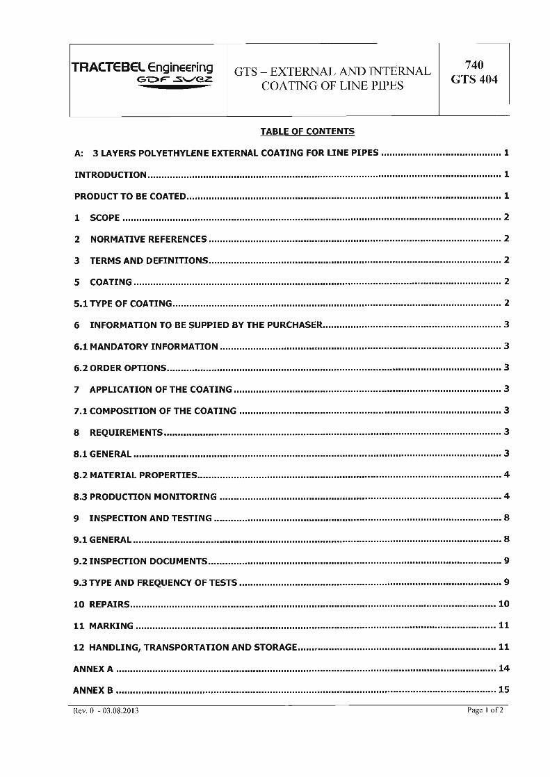
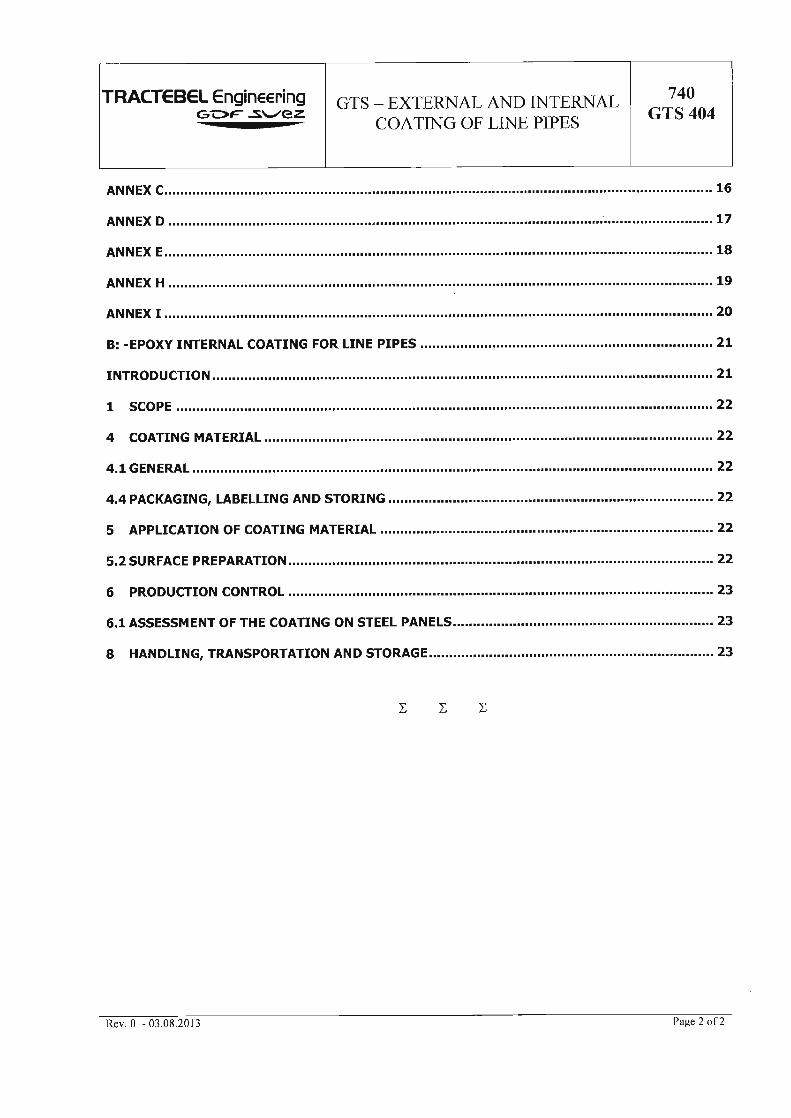


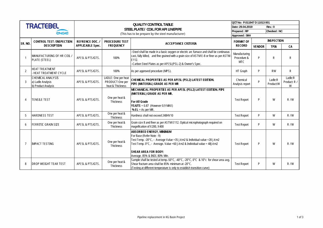
VENDOR TPIA CA
1 MANUFACTURING OF HR COIL /PLATE (STEEL) API 5L & PTS/GTS. 100%
–Steel shall be made in a basic oxygen or electric arc furnace and shall be continuouscast, fully killed, and fine grained with a grain size of ASTM E-8 or finer as per ASTM -E112.–Carbon Steel Plates as per API 5L(PSL-2) & Owner’s Spec.
ManufacturingProcedure &
MTCP R R
2 HEAT TREATMENT- HEAT TREATMENT CYCLE API 5L & PTS/GTS. 100% As per approved procedure (MPS). HT Graph P RW R
3CHEMICAL ANALYSISa) Ladle Analysisb) Product Analysis
API 5L & PTS/GTS.LADLE: One per heatPRODUCT:One per
heat & Thickness
CHEMICAL PROPERTIES AS PER API 5L (PSL2) LATEST EDITION.PIPE (MATERIAL) GRADE AS PER MR
ChemicalAnalysis report P Ladle:R
Product:W
Ladle:RProduct: R /
W
4 TENSILE TEST API 5L & PTS/GTS. One per heat &Thickness
MECHANICAL PROPERTIES AS PER API 5L (PSL2) LATEST EDITION. PIPE(MATERIAL) GRADE AS PER MR.
For All GradeYS/UTS = 0.87 (However 0.9 MAX)% EL = As per MR.
Test Report P W R / W
5 HARDNESS TEST API 5L & PTS/GTS. One per heat &Thickness Hardness shall not exceed 248HV10 Test Report P W R / W
6 FERRITIC GRAIN SIZE API 5L & PTS/GTS. One per heat &Thickness
Grain size 8 and finer as per ASTM E112. Optical microphotograph required onmagnification of X200, X400 Test Report P W R / W
7 IMPACT TESTING API 5L & PTS/GTS. One per heat &Thickness
ABSORBED ENERGY, MINIMUMFor Base (Refer Note : 9)Test Temp. -20°C, - Average Value =35 J/cm2 & Individual value =28 J/cm2Test Temp. 0°C, - Average. Value =60 J/cm2 & Individual value = 48J/cm2
SHEAR AREA FOR BODY:Average. 85% & INDI. 80% Min.
Test Report P W R / W
8 DROP WEIGHT TEAR TEST API 5L & PTS/GTS. One per heat &Thickness
Sample shall be tested at temp.-50°C, -40°C, -20°C, 0°C & 10°c for shear area avg.Shear fracture area shall be 85% minimum at -20°C.(Testing at different temperature is only to establish transition curve)
Test Report P W R / W
CONTROL TEST / INSPECTIONDESCRIPTION
REFRENCE DOC. /APPLICABLE Spec.
Prepared : RP Checked : NCApproved : SKH
QUALITY CONTROL TABLESTEEL PLATE / COIL FOR API LINEPIPE
(This has to be prepare by the steel manufacturer)
PROCEDURE TESTFREQUENCY
Date: 29.04.2019 Rev.: 0QCT No: P.011947 D 11013 001
INSPECTIONFORMAT OFRECORDACCEPTANCE CRITERIASR. NO.
Pipeline replacement in KG Basin Project 1 of 3

VENDOR TPIA CACONTROL TEST / INSPECTION
DESCRIPTIONREFRENCE DOC. /APPLICABLE Spec.
Prepared : RP Checked : NCApproved : SKH
QUALITY CONTROL TABLESTEEL PLATE / COIL FOR API LINEPIPE
(This has to be prepare by the steel manufacturer)
PROCEDURE TESTFREQUENCY
Date: 29.04.2019 Rev.: 0QCT No: P.011947 D 11013 001
INSPECTIONFORMAT OFRECORDACCEPTANCE CRITERIASR. NO.
Plate UT will be carried out as per PTS / GTS / API 5L PSL2 & ISO-10893-9.The entire width and length of HR Coil/Plate shall be Ultrasonic tested by placing arrayprobes on the HR Coil/Plate surface in such a way that it cover 100% of the surfacearea. The height of indication having amplitude beyond the reference accepted signalheight (100% at 80% FSH) is considered as defective indication. All such AUTindication shall be cross checked by manual UT for confirmation. Audio & visual paintmark. Auto UT records shall be maintained in computer.
Any lamination exceeding the following will be considered as a defect.A) For Edge - any defect with ≥ 40 mm in any direction is unacceptable.- defect with length < 40 mm are acceptable provided the number does not exceed 3per meter of edge length. Acceptance as per ISO-10893-9 acceptance level U2.
B) For Body - the requirement for remaining portion of HR Coil/Plate shall beevaluation for their acceptance as per ISO-10893-9 acceptance level U2.
Calibration Block shall be from same grade metal / plate.Calibration Block for Plate/Coil - Slot (8 X 1/2 thick / full width of HR. Coil/Plate).
Calibration Block for Edges/Pipe ends - shall have 6.4mm dia. FBH of depth 0.5twhere "t" is specified wall thickness.
Calibration Frequency - At the beginning of each operating shift and subsequentlythan every 4hrs during continuous equipment operation. Every time during the runningof system gives rise to doubts on its efficiency.
10 RETEST PTS/GTS If any
In case any of the test specimens fails to conform to specification requirment, a retestof two additional samples from the same heat shall be made. If all the tests givepositive results pertaining to all the parameters related to the test then the coil/ plateshall be accepted, otherwise the respecive coil/ plate, which gave negative results,shall be rejected. In case the results of one of the test specimen is negative than at theoption of purchaser/ owner either heat may be rejected or each of the remaining coilshall be individually tested. Only those coil/plate, Which satisfy the requirments of thisspecification shall be accepted.
Retest Report P W R / W
11
11.1 VISUAL API 5L & PTS/GTS. Two Plate perThickness and Heat.
- Free from defect.- No repair shall be permitted.- Straightness and waviness shall not be acceptable.
VisualInspection
ReportP RW R / W
11.2 WIDTH API 5L & PTS/GTS. –0.0/+20 MM
ULTRASONIC TEST API 5L & PTS/GTS. 100% Coil AreaCoverage
VISUAL & DIMENSIONAL INSPECTION
Dimesion
UT Report P W R / W
Two Plate per
9
Pipeline replacement in KG Basin Project 2 of 3
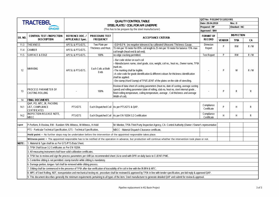
VENDOR TPIA CACONTROL TEST / INSPECTION
DESCRIPTIONREFRENCE DOC. /APPLICABLE Spec.
Prepared : RP Checked : NCApproved : SKH
QUALITY CONTROL TABLESTEEL PLATE / COIL FOR API LINEPIPE
(This has to be prepare by the steel manufacturer)
PROCEDURE TESTFREQUENCY
Date: 29.04.2019 Rev.: 0QCT No: P.011947 D 11013 001
INSPECTIONFORMAT OFRECORDACCEPTANCE CRITERIASR. NO.
11.3 THICKNESS API 5L & PTS/GTS. –0.0/+8.0 % (no negative tolerance) by calibrated Ultrasonic Thickness Gauge.
11.4 CAMBER API 5L & PTS/GTS. 15 mm per 10 meter for 85% coil length & 25 mm per 10 meter for balance 15% maxcoil length (head end & tail end).
11.5 SURFACE & EDGE API 5L & PTS/GTS. 100% no edge cracking permitted. Test Report P RW R / W
12 MARKING API 5L & PTS/GTS. Each Coils at BothEnds
– Bar code sticker on each coil– Manufacturers name, steel grade, size, weight, coil no., heat no., Owner name, TPIAmark etc.–The marking shall be legible.–A color code for grade identification & different colours for thickness identificationshall be applied.–Die stamp (Hard Stamp) of TPI/CLIENT of the plates on the side of stenciling.
- P W R / W
13 PROCESS PARAMETER OFCASTING ROLLING - 100%
Review of data sheet of casting parameters (heat no, date of casting, average castingspeed) and rolling parameter (date of rolling, slab no, heat no, steel internal grade ,finish rolling temperature, coiling temperature, average . Coil thickness and averageWidth of coil).
- P R R
14
14.1QAP, PO, MTC, IR, PACKINGLIST, COMPLIANCECERTIFICATES
PTS/GTS Each Dispatched Coil As per PTS/GTS & QAP. ComplianceCertificate P H R
14.2 INSPECTION RELEASE NOTE,MDCC PTS/GTS Each Dispatched Coil As per EN 10204 3.2 Certification Compliance
Certificate H H R
Legend: P-Perform, R-Review, RW - Random 10% Witness, W-Witness, H-Hold M- Monitor, TPIA-Third Party Inspection Agency, CA- Control Authority (Owner / Owner's representative
MDCC - Material Dispatch Clearance certificate,Hold point = No further steps may be undertaken before the intervention of the appointed responsible takes place.
Witness point = The appointed responsible has to be notified of the operation in advance, but production will continue whether the intervention took place or not.
NOTE :
PTS - Particular Technical Specification, GTS - Technical Specification,
FINAL DOCUMENTS
RWDimesionReport P R / W
1. Material & Type shall be as Per GTS/PTS/Data Sheet.2. TPIA Shall Issue 3.2 Certificates as Per EN 10204.3. All measuring instrument shall have valid calibration certificates.4. TPIA has to review and sign the process parameters per shift (as recommended sheet ) & to send with DPR on daily basis to CLIENT/ PMC.5. Centerline slitting is not permitted. stamp transfer while slitting is mandatory.6. Damage portion, tongue / tail shall be removed while slitting process.7. Slitting shall be commenced in the presense of TPIA after due verification of traceability of hr coil in line with the IR/IRN & MTC.8. MPS of Steel Rolling, NDT, transportation and mechanical testing etc. procedure shall be reviewed & approved by TPIA in line with tender specification, pre-bid reply & approved QAP.9. This document describes generally the minimum requirements pertaining to all types of the item. Steel manufacturer to generate detailed QAP and submit for review & approval.
Two Plate perThickness and Heat.
Pipeline replacement in KG Basin Project 3 of 3

PQT/ FDPT REGULARPRODUCTION
PQT/FDPT REG. PROD.
First Day Production Test PTS / GTS /API 5L MPQT report P H - H
1
B. REVIEW OF QAP, MPS. PTS / GTS / API 5L ---- ---- Coil MILL TC & IRN P R R A
A. MANUFACTURING OF HR STEEL PTS / GTS / API 5L ---- ---- Coil MILL TC & IRN P R R R
B. REVIEW OF RAW MATERIAL T.C.(Certificate 3.2 as per EN 10204), IRN, IRINCLUDING PACKING LIST
PTS / GTS / API 5L Coil MILL TC & IRN P RW RW R / W
C. QMS PTS / GTS / ISO9001 P R R A
D. INSPECTION & IDENTIFICATION ---- Inspection Report P W W R / W
2 UNCOILING PTS / GTS / API 5L Inspection Report P W W R / W
3 ONLINE UT OF HR COIL / PLATE PTS / GTS / API 5L Each Coil Each Coil(100% area coverage) Online AUT Report P W W R / W
4 MANUAL UT FOR CROSS-CHECKINGONLINE UT INDICATIONS PTS / GTS / API 5L
Untested & Suspectedarea which is marked
by AUT.
Untested & Suspectedarea which is marked
by AUT.MUT Report P W W R / W
5 EDGE MILLING PTS / GTS / API 5L Inspection Report P W RW R
6 CRIMPING (IF APPLICABLE) PTS / GTS / API 5L Each Pipe Each Pipe Production Report P W RW R / W
QCT No: P.011947 D 11013 002
Date: 29.04.2019 Rev.: 0
Prepared : RP Checked : NC
Approved : SKH
SR. No. CONTROL TEST/INSPECTIONDESCRIPTION
REFF. DOCS./APPLICABLE
SEPC.
PROCEDURE TEST FREQUENCY
ACCEPTANCE CRITERIA FORMAT OFRECORD
INSPECTION
REMARKSMANUF. /SUPPLIER
TPIA CONTROLAUTHORITY
(CA)
Both the edges of the plates are curved by crimping press. Pre-forming (crimping) assistance inproviding the proper pipe curvature along the weld seam.
QUALITY CONTROL TABLE(ANNEXURE - Q - PURCHASER INDICATIVE INSPECTION AND QUALITY PLAN)
LINE PIPES - SUBMERGED ARC LONGITUDINAL WELDING (BARE)
RAW MATERIAL
QAP / MPS of steel plate / coil from steel mill shall be submitted after reviewed at Pipe Mill forreview & approval of Owner / Owner's representative.
Raw Material Testing shall Be Witnessed & Reviewed By TPIA at Steel Mill & also samereviewed at Pipe Mill
MPS / WPS / PQT / EQT ETC.
Physical verification of coil / plate no. & heat no. according to raw material TC & dimensioncheck. Verification of TPIA stamp of coil / plate.
All the indication from the online coil UT shall be cross checked by manual UT using TR probefor their evaluation and acceptance - same as mentioned for online coil UT
CALIBRATION FREQUENCY - At the beginning of each shift and subsequent at every 4hours.
Edge shape : Double V / Single V (As per approved WPS)both the edges of the coil shall be milled & controlled by the setting of milling cutter.Each Coil / Plate
Each Heat
Each Coil / Plate
Each Coil
Checking of material size, heat, and coil no and visual & dimension check , free from defectThickness and width (by d-meter and tape)Width: -0 + 20mmW.t.: +10%, no negetive tolerance is allowed.- Shearing of coil to plate (cut-to-length) shall be done under the monitoring of TPIA
The entire width and length of HR Coil/Plate shall be tested by placing array probes on the HRCoil/Plate surface in such a way that it cover 100% of the surface area.The height of indicationhaving amplitude beyond the reference accepted signal height (100% at 80% FSH) is consideredas defective indication. All such aut indication shall be cross checked by manual ut forconfiormation.
Audio visual & paint mark.Any lamination exceeding the following will be considered as a defect.
A) For Edge- any defect with ≥ 40 mm in any direction is unacceptable defect with length < 40mm are acceptable provided the number does not exceed 3 per meter of edge length.
B) For Body- the requirement for remaining portion of HR Coil/Plate shall be evaluation for theiracceptance as per iso 10893-9 acceptance level U2.
Calibration stands for Plate/Coil- Slot (8 X 1/2 thick / full width of HR Coil/Plate) Calibrationstands for Edges/Piep ends - shall have 6.4mm dia. FBH of depth 0.5t where "t" is specified wallthickness.
Calibration Frequency - At the beginning of each operating shift and subsequently than every 4hrs during continuous equipment operation. Every time during the running of system gives rise todoubts on its efficiency.
3 pipes from 3 different heats shall be selected at random covering each welding line (internal &external) to be selected for testing for each size, grade and wall thickness.
Steel Shall Be Made in a Basic oxygen or Electric Arc Furnace and shall be continuous cast, FullyKilled, and fine grained with a grain size of ASTM E-7 or Finer as per ASTM - E112
Pipeline replacement in KG Basin Project 1 of 6
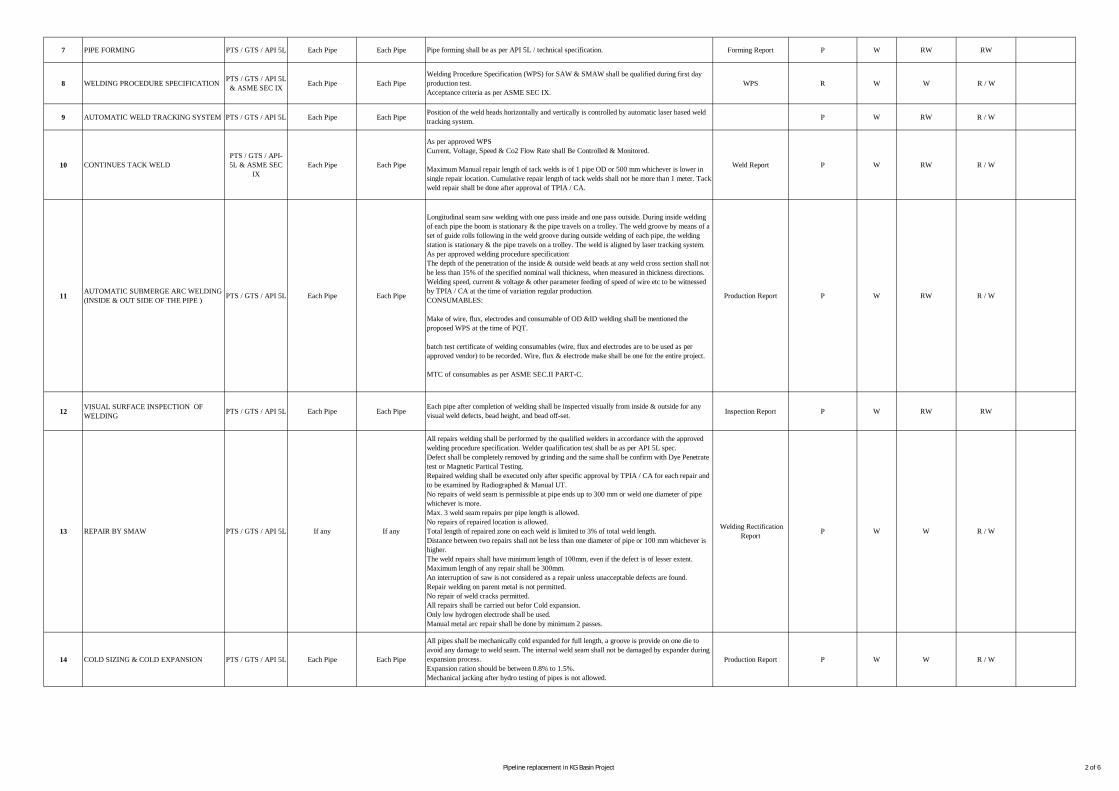
7 PIPE FORMING PTS / GTS / API 5L Each Pipe Each Pipe Forming Report P W RW RW
8 WELDING PROCEDURE SPECIFICATION PTS / GTS / API 5L& ASME SEC IX Each Pipe Each Pipe WPS R W W R / W
9 AUTOMATIC WELD TRACKING SYSTEM PTS / GTS / API 5L Each Pipe Each Pipe P W RW R / W
10 CONTINUES TACK WELDPTS / GTS / API-5L & ASME SEC
IXEach Pipe Each Pipe Weld Report P W RW R / W
11 AUTOMATIC SUBMERGE ARC WELDING(INSIDE & OUT SIDE OF THE PIPE ) PTS / GTS / API 5L Each Pipe Each Pipe Production Report P W RW R / W
12 VISUAL SURFACE INSPECTION OFWELDING PTS / GTS / API 5L Each Pipe Each Pipe Inspection Report P W RW RW
14 COLD SIZING & COLD EXPANSION PTS / GTS / API 5L Each Pipe Each Pipe Production Report P W W R / W
Position of the weld heads horizontally and vertically is controlled by automatic laser based weldtracking system.
As per approved WPSCurrent, Voltage, Speed & Co2 Flow Rate shall Be Controlled & Monitored.
Maximum Manual repair length of tack welds is of 1 pipe OD or 500 mm whichever is lower insingle repair location. Cumulative repair length of tack welds shall not be more than 1 meter. Tackweld repair shall be done after approval of TPIA / CA.
Longitudinal seam saw welding with one pass inside and one pass outside. During inside weldingof each pipe the boom is stationary & the pipe travels on a trolley. The weld groove by means of aset of guide rolls following in the weld groove during outside welding of each pipe, the weldingstation is stationary & the pipe travels on a trolley. The weld is aligned by laser tracking system.As per approved welding procedure specification:The depth of the penetration of the inside & outside weld beads at any weld cross section shall notbe less than 15% of the specified nominal wall thickness, when measured in thickness directions.Welding speed, current & voltage & other parameter feeding of speed of wire etc to be witnessedby TPIA / CA at the time of variation regular production.CONSUMABLES:
Make of wire, flux, electrodes and consumable of OD &ID welding shall be mentioned theproposed WPS at the time of PQT.
batch test certificate of welding consumables (wire, flux and electrodes are to be used as perapproved vendor) to be recorded. Wire, flux & electrode make shall be one for the entire project.
MTC of consumables as per ASME SEC.II PART-C.
Each pipe after completion of welding shall be inspected visually from inside & outside for anyvisual weld defects, bead height, and bead off-set.
All pipes shall be mechanically cold expanded for full length, a groove is provide on one die toavoid any damage to weld seam. The internal weld seam shall not be damaged by expander duringexpansion process.Expansion ration should be between 0.8% to 1.5%.Mechanical jacking after hydro testing of pipes is not allowed.
Pipe forming shall be as per API 5L / technical specification.
Welding Procedure Specification (WPS) for SAW & SMAW shall be qualified during first dayproduction test.Acceptance criteria as per ASME SEC IX.
Welding RectificationReport P W13 REPAIR BY SMAW PTS / GTS / API 5L If any If any
All repairs welding shall be performed by the qualified welders in accordance with the approvedwelding procedure specification. Welder qualification test shall be as per API 5L spec.Defect shall be completely removed by grinding and the same shall be confirm with Dye Penetratetest or Magnetic Partical Testing.Repaired welding shall be executed only after specific approval by TPIA / CA for each repair andto be examined by Radiographed & Manual UT.No repairs of weld seam is permissible at pipe ends up to 300 mm or weld one diameter of pipewhichever is more.Max. 3 weld seam repairs per pipe length is allowed.No repairs of repaired location is allowed.Total length of repaired zone on each weld is limited to 3% of total weld length.Distance between two repairs shall not be less than one diameter of pipe or 100 mm whichever ishigher.The weld repairs shall have minimum length of 100mm, even if the defect is of lesser extent.Maximum length of any repair shall be 300mm.An interruption of saw is not considered as a repair unless unacceptable defects are found.Repair welding on parent metal is not permitted.No repair of weld cracks permitted.All repairs shall be carried out befor Cold expansion.Only low hydrogen electrode shall be used.Manual metal arc repair shall be done by minimum 2 passes.
W R / W
Pipeline replacement in KG Basin Project 2 of 6
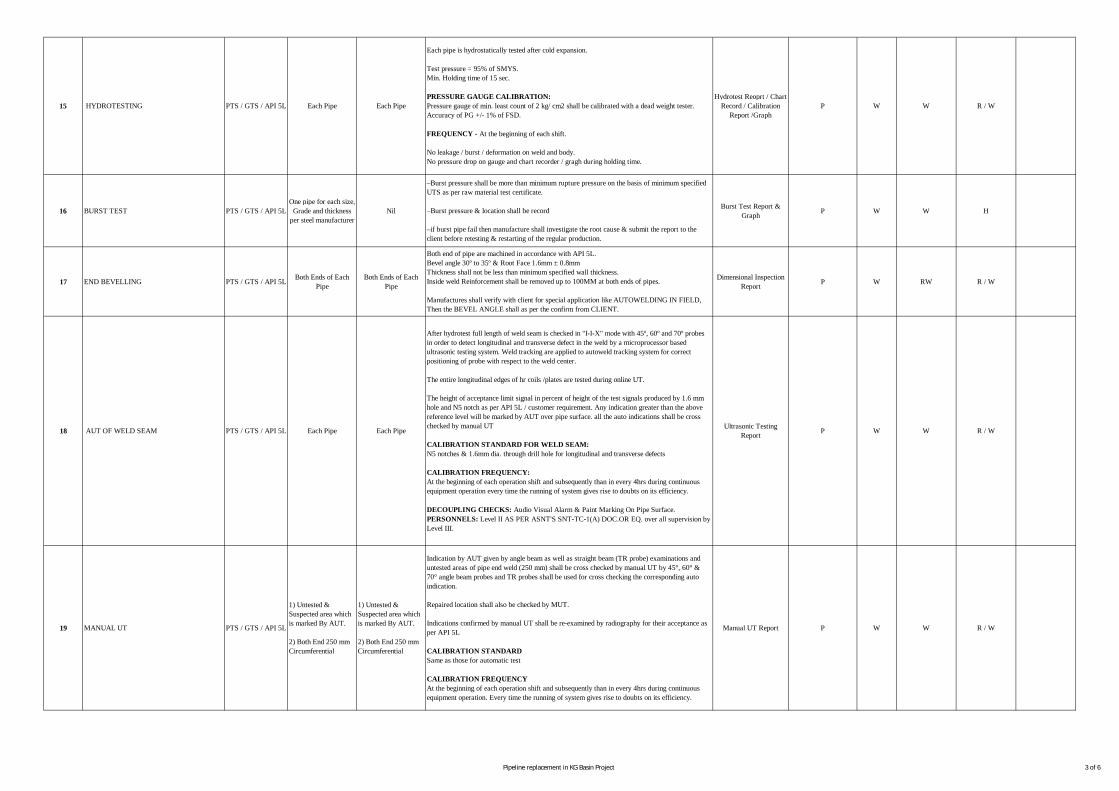
16 BURST TEST PTS / GTS / API 5LOne pipe for each size,
Grade and thicknessper steel manufacturer
Nil Burst Test Report &Graph P W W H
17 END BEVELLING PTS / GTS / API 5L Both Ends of EachPipe
Both Ends of EachPipe
Dimensional InspectionReport P W RW R / W
15 HYDROTESTING PTS / GTS / API 5L Each Pipe Each Pipe
Each pipe is hydrostatically tested after cold expansion.
Test pressure = 95% of SMYS.Min. Holding time of 15 sec.
PRESSURE GAUGE CALIBRATION:Pressure gauge of min. least count of 2 kg/ cm2 shall be calibrated with a dead weight tester.Accuracy of PG +/- 1% of FSD.
FREQUENCY - At the beginning of each shift.
No leakage / burst / deformation on weld and body.No pressure drop on gauge and chart recorder / gragh during holding time.
P W W R / W
–Burst pressure shall be more than minimum rupture pressure on the basis of minimum specifiedUTS as per raw material test certificate.
–Burst pressure & location shall be record
–if burst pipe fail then manufacture shall investigate the root cause & submit the report to theclient before retesting & restarting of the regular production.
18 AUT OF WELD SEAM PTS / GTS / API 5L Each Pipe Each Pipe
After hydrotest full length of weld seam is checked in "I-I-X" mode with 45º, 60º and 70º probesin order to detect longitudinal and transverse defect in the weld by a microprocessor basedultrasonic testing system. Weld tracking are applied to autoweld tracking system for correctpositioning of probe with respect to the weld center.
The entire longitudinal edges of hr coils /plates are tested during online UT.
The height of acceptance limit signal in percent of height of the test signals produced by 1.6 mmhole and N5 notch as per API 5L / customer requirement. Any indication greater than the abovereference level will be marked by AUT over pipe surface. all the auto indications shall be crosschecked by manual UT
CALIBRATION STANDARD FOR WELD SEAM:N5 notches & 1.6mm dia. through drill hole for longitudinal and transverse defects
CALIBRATION FREQUENCY:At the beginning of each operation shift and subsequently than in every 4hrs during continuousequipment operation every time the running of system gives rise to doubts on its efficiency.
DECOUPLING CHECKS: Audio Visual Alarm & Paint Marking On Pipe Surface.PERSONNELS: Level II AS PER ASNT'S SNT-TC-1(A) DOC.OR EQ. over all supervision byLevel III.
Hydrotest Reoprt / ChartRecord / Calibration
Report /Graph
Both end of pipe are machined in accordance with API 5L.Bevel angle 30º to 35º & Root Face 1.6mm ± 0.8mmThickness shall not be less than minimum specified wall thickness.Inside weld Reinforcement shall be removed up to 100MM at both ends of pipes.
Manufactures shall verify with client for special application like AUTOWELDING IN FIELD,Then the BEVEL ANGLE shall as per the confirm from CLIENT.
W R / W
19 MANUAL UT PTS / GTS / API 5L
1) Untested &Suspected area whichis marked By AUT.
2) Both End 250 mmCircumferential
1) Untested &Suspected area whichis marked By AUT.
2) Both End 250 mmCircumferential
Indication by AUT given by angle beam as well as straight beam (TR probe) examinations anduntested areas of pipe end weld (250 mm) shall be cross checked by manual UT by 45°, 60° &70° angle beam probes and TR probes shall be used for cross checking the corresponding autoindication.
Repaired location shall also be checked by MUT.
Indications confirmed by manual UT shall be re-examined by radiography for their acceptance asper API 5L
CALIBRATION STANDARDSame as those for automatic test
CALIBRATION FREQUENCYAt the beginning of each operation shift and subsequently than in every 4hrs during continuousequipment operation. Every time the running of system gives rise to doubts on its efficiency.
Ultrasonic TestingReport P W
Manual UT Report P W W R / W
Pipeline replacement in KG Basin Project 3 of 6
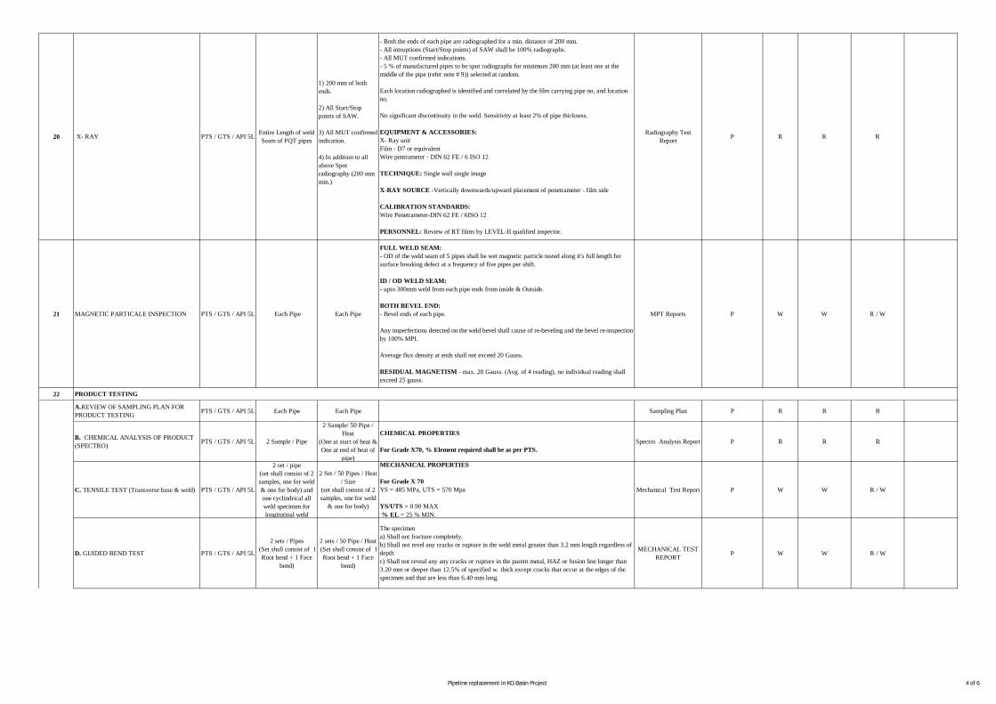
21 MAGNETIC PARTICALE INSPECTION PTS / GTS / API 5L Each Pipe Each Pipe MPT Reports P W W R / W
22
A.REVIEW OF SAMPLING PLAN FORPRODUCT TESTING PTS / GTS / API 5L Each Pipe Each Pipe Sampling Plan P R R R
B. CHEMICAL ANALYSIS OF PRODUCT(SPECTRO) PTS / GTS / API 5L 2 Sample / Pipe
2 Sample/ 50 Pipe /Heat
(One at start of heat &One at end of heat of
pipe)
Spectro Analysis Report P R R R
C. TENSILE TEST (Transverse base & weld) PTS / GTS / API 5L
2 set / pipe(set shall consist of 2samples, one for weld& one for body) andone cyclindrical allweld specimen forlongitutinal weld
2 Set / 50 Pipes / Heat/ Size
(set shall consist of 2samples, one for weld
& one for body)
Mechanical Test Report P W W R / W
D. GUIDED BEND TEST PTS / GTS / API 5L
2 sets / Pipes (Set shall consist of 1
Root bend + 1 Facebend)
2 sets / 50 Pipe / Heat (Set shall consist of 1
Root bend + 1 Facebend)
MECHANICAL TESTREPORT P W W R / W
20 X- RAY PTS / GTS / API 5L Entire Length of weldSeam of PQT pipes
1) 200 mm of bothends.
2) All Start/Stoppoints of SAW.
3) All MUT confirmedindication.
4) In addition to allabove Spotradiography (200 mmmin.)
- Both the ends of each pipe are radiographed for a min. distance of 200 mm.- All intruptions (Start/Stop points) of SAW shall be 100% radiographs.- All MUT confirmed indications.- 5 % of manufactured pipes to be spot radiographs for minimum 200 mm (at least one at themiddle of the pipe (refer note # 9)) selected at random.
Each location radiographed is identified and correlated by the film carrying pipe no, and locationno.
No significant discontinuity in the weld. Sensitivity at least 2% of pipe thickness.
EQUIPMENT & ACCESSORIES:X- Ray unitFilm - D7 or equivalentWire pentrameter - DIN 62 FE / 6 ISO 12
TECHNIQUE: Single wall single image
X-RAY SOURCE -Vertically downwards/upward placement of penetrameter - film side
CALIBRATION STANDARDS:Wire Penetrameter-DIN 62 FE / 6ISO 12
PERSONNEL: Review of RT films by LEVEL-II qualified inspector.
Radiography TestReport P R
FULL WELD SEAM:- OD of the weld seam of 5 pipes shall be wet magnetic particle tested along it's full length forsurface breaking defect at a frequency of five pipes per shift.
ID / OD WELD SEAM:- upto 300mm weld from each pipe ends from inside & Outside.
BOTH BEVEL END:- Bevel ends of each pipe.
Any imperfections detected on the weld bevel shall cause of re-beveling and the bevel re-inspectionby 100% MPI.
Average flux density at ends shall not exceed 20 Gauss.
RESIDUAL MAGNETISM - max. 20 Gauss. (Avg. of 4 reading), no individual reading shallexceed 25 gauss.
PRODUCT TESTING
The specimena) Shall not fracture completely.b) Shall not revel any cracks or rupture in the weld metal greater than 3.2 mm length regardless ofdepthc) Shall not reveal any any cracks or rupture in the parent metal, HAZ or fusion line longer than3.20 mm or deeper than 12.5% of specified w. thick except cracks that occur at the edges of thespecimen and that are less than 6.40 mm long.
R R
CHEMICAL PROPERTIES
For Grade X70, % Element required shall be as per PTS.
MECHANICAL PROPERTIES
For Grade X 70YS = 485 MPa, UTS = 570 Mpa
YS/UTS = 0.90 MAX% EL = 25 % MIN.
Pipeline replacement in KG Basin Project 4 of 6
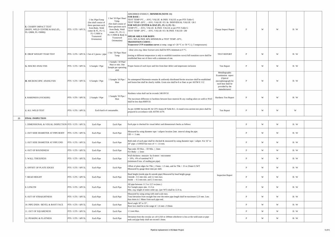
E. CHARPY IMPACT TEST(BODY, WELD CENTRE & HAZ (FL,FL+2MM, FL+5MM))
PTS / GTS / API 5L
1 Set /Pipe/Temp(Set shall consist ofthree specimen each
from Body, Weldcenter & FL, FL+2,
FL+5 MM inTranseverdOrientation)
1 Set/ 50 Pipe/ Heat/Temp.
(Set shall consist ofthree specimen each
from Body, Weldcenter, FL, FL+2,
FL+5 MM & Body inTranseverdOrientation)
Charpy Impact Report P W W R / W
F. DROP WEIGHT TEAR TEST PTS / GTS / API 5L 1 Set of 2 pieces / pipe 1 Set / 50 Pipe/ Heat/Temp TEST REPORT P W W R / W
G. MACRO ANALYSIS PTS / GTS / API 5L 6 Sample / Pipe
1 Sample / 50 Pipe/Heat or min. One
Sample per operatingshift
Test Report P W W R / W
H. MICROSCOPIC ANANLYSIS PTS / GTS / API 5L 6 Sample / Pipe 1 Sample/ 50 Pipe /Heat
MetallographicExamination report
(Opticalmicrophotograph for
each heat shall beprovided by themanufacturer)
P W W R / W
I. HARDNESS (VICKERS) PTS / GTS / API 5L 2 Sample / Pipe 1 Sample/ 50 Pipe /Heat Hardness Test Report P W W R / W
J. ALL WELD TEST PTS / GTS / API 5L Test Report P W W W
23
1. DIMENSIONAL & VISUAL INSPECTION PTS / GTS / API 5L Each Pipe Each Pipe P W W R / W
2. OUT SIDE DIAMETER AT PIPE BODY PTS / GTS / API 5L Each Pipe Each Pipe P W W R / W
3. OUT SIDE DIAMETER AT PIPE END PTS / GTS / API 5L Each Pipe Each Pipe P W W R / W
4. OUT OF ROUNDNESS PTS / GTS / API 5L Each Pipe Each Pipe P W W R / W
5. WALL THICKNESS PTS / GTS / API 5L Each Pipe Each Pipe P W W R / W
6. OFFSET OF PLATE EDGES PTS / GTS / API 5L Each Pipe Each Pipe P W W R / W
7. BEAD HEIGHT PTS / GTS / API 5L Each Pipe Each Pipe P W W R / W
8. LENGTH PTS / GTS / API 5L Each Pipe Each Pipe P W W R / W
9. OUT OF STRAIGHTNESS PTS / GTS / API 5L Each Pipe Each Pipe P W W R / W
10. PIPE ENDS / BEVEL & ROOT FACE PTS / GTS / API 5L Each Pipe Each Pipe P W W R / W
11. OUT OF SQUARENESS PTS / GTS / API 5L Each Pipe Each Pipe P W W R / W
12. PEAKING & FLATNESS PTS / GTS / API 5L Each Pipe Each Pipe P W W R / W
Pipe ends: ID Max. - ID Min. < 3mmFor Body - < 5mm
Measured by using string with steel scale max.Total deviation from straight line over the entire pipe length shall be maximum 12.0 mm. Lessthan 4mm in 1 Meter from each pipe end.
Hardness value shall not be exceeds 248 HV10
The maximum difference in hardness between base material & any reading taken on weld or HAZshall be less than 80HV10.
- shear area avg. shear fracture area shall be 85% minimum at 0 °C.
(testing at different temperature is only to establish transition curve) full transition curve shall beestablished heat out of three with a minimum of one.
No untempered Martensite remains & uniformly distributed ferrite structure shall be establishedand fusion line shall be clearly visible. Grain size shall be 8 or finer as per ASTM E 112
Each batch of consumable.
Each pipe is checked for visual defect and dimensional checks as follows
Measured by using diameter tape / calipers location 2mtr. interval along the pipe.OD +/- 3 mm.
Both ends of each pipe shall be checked & measured by using diameter tape / caliper. For 16" to20" pipe + 0.005D but max of +/- 1.6 mm.
Wall thickness measure by d-meter / micrometer+ 10%, -0% of nomimal W.T(minimum 8 nos. of reading per pipe)
Offset of plate edges for Thk < 15mm : 1.5 mm, and for Thk > 15 to 25mm 0.1WTMeasured by gauge three time per shift.
Bead height (inside pipe & outside pipe) Measured by bead height gauge.Outside - 0.5 mm min. and 3.2 mm max.Inside - 0.5 mm min. and 2.5 mm max.
All pipe between 11.5 to 12.5 m (max.)For Sample pipes min. 11.0 mMin. avg. length of entire order qty. (per WT) shall be 12.0 m.
Bevel angle 30º to 35º ,Root face shall be in the range of 1.6 mm ± 0.8mm
1.5 mm Max.
Deviation from the circular arc of 0.25D or 200mm whichever is less at the weld seam at pipeends and pipe body shall not exceed 1.6mm.
Inspection Report
As per ASME Section-IIC & GTS Annex.B Table B.1. A round cross-section test piece shall beprepared in accordance with ASTM A370.
FINAL INSPECTION
ABSORBED ENERGY, MINIMUM (NOTE 11)FOR BASE :TEST TEMP 0°C , - AVG. VALUE & INDI. VALUE as per PTS Table GTEST TEMP -20°C , - AVG. VALUE=35 J & INDIVIDUAL VALUE =28 JFOR WELD CENTER & HAZ (FL, FL+2, FL+5) :TEMP 0°C , - AVG. VALUE & INDI. VALUE as per PTS Table GTEST TEMP -20°C , - AVG. VALUE=35 J & INDI. VALUE= 28J
SHEAR AREA FOR BODY:AVG. 90% & INDI. 80% MINIMUM at TEST TEMP -20°C,TRANSITION CURVE :Transverse CVN transition curves at temp. range of +20 °C to -50 °C (> 5 temperatures)
Proper fusion of each layer and free from liner defect and importance inclusion
Pipeline replacement in KG Basin Project 5 of 6
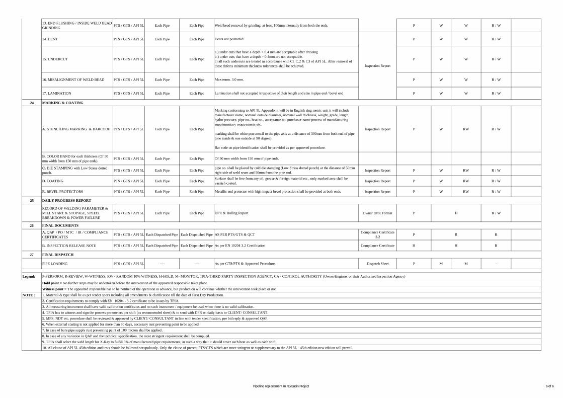
13. END FLUSHING / INSIDE WELD BEADGRINDING PTS / GTS / API 5L Each Pipe Each Pipe P W W R / W
14. DENT PTS / GTS / API 5L Each Pipe Each Pipe P W W R / W
15. UNDERCUT PTS / GTS / API 5L Each Pipe Each Pipe P W W R / W
16. MISALIGNMENT OF WELD BEAD PTS / GTS / API 5L Each Pipe Each Pipe P W W R / W
17. LAMINATION PTS / GTS / API 5L Each Pipe Each Pipe P W W R / W
24
A. STENCILING MARKING & BARCODE PTS / GTS / API 5L Each Pipe Each Pipe Inspection Report P W RW R / W
B. COLOR BAND for each thickness (Of 50mm width from 150 mm of pipe ends). PTS / GTS / API 5L Each Pipe Each Pipe
C. DIE STAMPING with Low Stress dottedpunch. PTS / GTS / API 5L Each Pipe Each Pipe Inspection Report P W RW R / W
D. COATING PTS / GTS / API 5L Each Pipe Each Pipe Inspection Report P W RW R / W
E. BEVEL PROTECTORS PTS / GTS / API 5L Each Pipe Each Pipe Inspection Report P W RW R / W
25
RECORD OF WELDING PARAMETER &MILL START & STOPAGE, SPEED,BREAKDOWN & POWER FAILURE
PTS / GTS / API 5L Each Pipe Each Pipe Owner DPR Format P R / W
26
A. QAP / PO / MTC / IR / COMPLIANCECERTIFICATES PTS / GTS / API 5L Each Dispatched Pipe Each Dispatched Pipe Compliance Certificate
3.2 P R
B. INSPECTION RELEASE NOTE PTS / GTS / API 5L Each Dispatched Pipe Each Dispatched Pipe Compliance Certificate H R
27
PIPE LOADING PTS / GTS / API 5L ---- ---- Dispatch Sheet P M M -
Legend:
NOTE :
FINAL DISPATCH
As per GTS/PTS & Approved Procedure.
P-PERFORM, R-REVIEW, W-WITNESS, RW - RANDOM 10% WITNESS, H-HOLD, M- MONITOR, TPIA-THIRD PARTY INSPECTION AGENCY, CA - CONTROL AUTHORITY (Owner/Engineer or their Authorised Inspection Agency)
1. Material & type shall be as per tender specs including all amendments & clarification till the date of First Day Production.
DAILY PROGRESS REPORT
DPR & Rolling Report
FINAL DOCUMENTS
AS PER PTS/GTS & QCT
As per EN 10204 3.2 Certification
Hold point = No further steps may be undertaken before the intervention of the appointed responsible takes place.Witness point = The appointed responsible has to be notified of the operation in advance, but production will continue whether the intervention took place or not.
H
R
H
2. Certification requirements to comply with EN 10204 - 3.2 certificate to be issues by TPIA.3. All measuring instrument shall have valid calibration certificates and no such instrument / equipment be used when there is no valid calibration.4. TPIA has to witness and sign the process parameters per shift (as recommended sheet) & to send with DPR on daily basis to CLIENT/ CONSULTANT.5. MPS, NDT etc. procedure shall be reviewed & approved by CLIENT/ CONSULTANT in line with tender specification, pre bid reply & approved QAP.6. When external coating is not applied for more than 30 days, necessary rust preventing paint to be applied.7. In case of bare pipe supply rust preventing paint of 100 micron shall be applied .8. In case of any variation in QAP and the technical specification, the most stringent requirement shall be complied.
10. All clause of API 5L 45th edition and tests should be followed scrupulously. Only the clause of present PTS/GTS which are more stringent or supplementary to the API 5L - 45th edition new edition will prevail.9. TPIA shall select the weld length for X-Ray to fulfill 5% of manufactured pipe requirements, in such a way that it should cover each heat as well as each shift.
Of 50 mm width from 150 mm of pipe ends.
MARKING & COATING
Marking conforming to API 5L Appendix it will be in English sing metric unit it will includemanufacturer name, nominal outside diameter, nominal wall thickness, weight, grade, length,hydro pressure, pipe no., heat no., acceptance no. purchaser name process of manufacturingsupplementary requirements etc.
marking shall be white pen stencil to the pipe axis at a distance of 300mm from both end of pipe(one inside & one outside at 90 degree).
Bar code on pipe identification shall be provided as per approved procedure.
pipe no. shall be placed by cold die stamping (Low Stress dotted punch) at the distance of 50mmright side of weld seam and 50mm from the pipe end.Surface shall be free from any oil, grease & foreign material etc., only marked area shall bevarnish coated.
Metallic end protector with high impact bevel protection shall be provided at both ends.
Weld bead removal by grinding: at least 100mm internally from both the ends.
Dents not permitted.
a.) under cuts that have a depth < 0.4 mm are acceptable after dressingb.) under cuts that have a depth > 0.4mm are not acceptable.c) all such undercuts are treated in accordance with Cl. C.2 & C3 of API 5L. After removal ofthese defects minimum thickness tolerances shall be achieved.
Lamination shall not accepted irrespective of their length and size in pipe end / bevel end
Maximum. 3.0 mm.
Inspection Report
Pipeline replacement in KG Basin Project 6 of 6
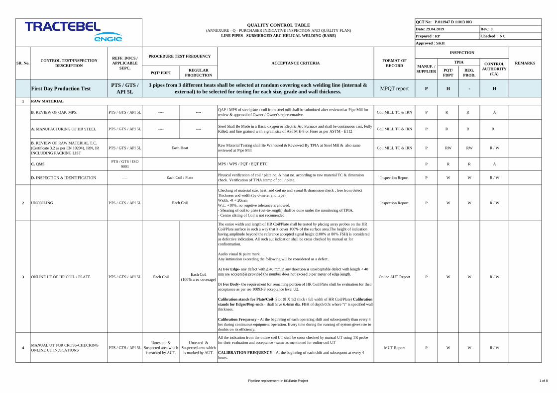
PQT/ FDPT REGULARPRODUCTION
PQT/FDPT
REG.PROD.
First Day Production Test PTS / GTS /API 5L MPQT report P H - H
1
B. REVIEW OF QAP, MPS. PTS / GTS / API 5L ---- ---- Coil MILL TC & IRN P R R A
A. MANUFACTURING OF HR STEEL PTS / GTS / API 5L ---- ---- Coil MILL TC & IRN P R R R
B. REVIEW OF RAW MATERIAL T.C.(Certificate 3.2 as per EN 10204), IRN, IRINCLUDING PACKING LIST
PTS / GTS / API 5L Coil MILL TC & IRN P RW RW R / W
C. QMS PTS / GTS / ISO9001 P R R A
D. INSPECTION & IDENTIFICATION ---- Inspection Report P W W R / W
2 UNCOILING PTS / GTS / API 5L Inspection Report P W W R / W
3 ONLINE UT OF HR COIL / PLATE PTS / GTS / API 5L Each Coil Each Coil(100% area coverage) Online AUT Report P W W R / W
4 MANUAL UT FOR CROSS-CHECKINGONLINE UT INDICATIONS PTS / GTS / API 5L
Untested &Suspected area whichis marked by AUT.
Untested &Suspected area whichis marked by AUT.
MUT Report P W W R / W
Rev.: 0
Checked : NC
QCT No: P.011947 D 11013 003
Date: 29.04.2019
Prepared : RP
Approved : SKH
QUALITY CONTROL TABLE(ANNEXURE - Q - PURCHASER INDICATIVE INSPECTION AND QUALITY PLAN)
LINE PIPES - SUBMERGED ARC HELICAL WELDING (BARE)
3 pipes from 3 different heats shall be selected at random covering each welding line (internal &external) to be selected for testing for each size, grade and wall thickness.
INSPECTION
CONTROLAUTHORITY
(CA)
REMARKSTPIACONTROL TEST/INSPECTIONDESCRIPTION
REFF. DOCS./APPLICABLE
SEPC.SR. No. ACCEPTANCE CRITERIA FORMAT OF
RECORD MANUF. /SUPPLIER
PROCEDURE TEST FREQUENCY
Each Heat
Each Coil / Plate
Each Coil
Checking of material size, heat, and coil no and visual & dimension check , free from defectThickness and width (by d-meter and tape)Width: -0 + 20mmW.t.: +10%, no negetive tolerance is allowed.- Shearing of coil to plate (cut-to-length) shall be done under the monitoring of TPIA.- Centre slitting of Coil is not recomended.
The entire width and length of HR Coil/Plate shall be tested by placing array probes on the HRCoil/Plate surface in such a way that it cover 100% of the surface area.The height of indicationhaving amplitude beyond the reference accepted signal height (100% at 80% FSH) is consideredas defective indication. All such aut indication shall be cross checked by manual ut forconfiormation.
Audio visual & paint mark.Any lamination exceeding the following will be considered as a defect.
A) For Edge- any defect with ≥ 40 mm in any direction is unacceptable defect with length < 40mm are acceptable provided the number does not exceed 3 per meter of edge length.
B) For Body- the requirement for remaining portion of HR Coil/Plate shall be evaluation for theiracceptance as per iso 10893-9 acceptance level U2.
Calibration stands for Plate/Coil- Slot (8 X 1/2 thick / full width of HR Coil/Plate) Calibrationstands for Edges/Piep ends - shall have 6.4mm dia. FBH of depth 0.5t where "t" is specified wallthickness.
Calibration Frequency - At the beginning of each operating shift and subsequently than every 4hrs during continuous equipment operation. Every time during the running of system gives rise todoubts on its efficiency.
Steel Shall Be Made in a Basic oxygen or Electric Arc Furnace and shall be continuous cast, FullyKilled, and fine grained with a grain size of ASTM E-8 or Finer as per ASTM - E112
RAW MATERIAL
QAP / MPS of steel plate / coil from steel mill shall be submitted after reviewed at Pipe Mill forreview & approval of Owner / Owner's representative.
Raw Material Testing shall Be Witnessed & Reviewed By TPIA at Steel Mill & also samereviewed at Pipe Mill
MPS / WPS / PQT / EQT ETC.
Physical verification of coil / plate no. & heat no. according to raw material TC & dimensioncheck. Verification of TPIA stamp of coil / plate.
All the indication from the online coil UT shall be cross checked by manual UT using TR probefor their evaluation and acceptance - same as mentioned for online coil UT
CALIBRATION FREQUENCY - At the beginning of each shift and subsequent at every 4hours.
Pipeline replacement in KG Basin Project 1 of 8
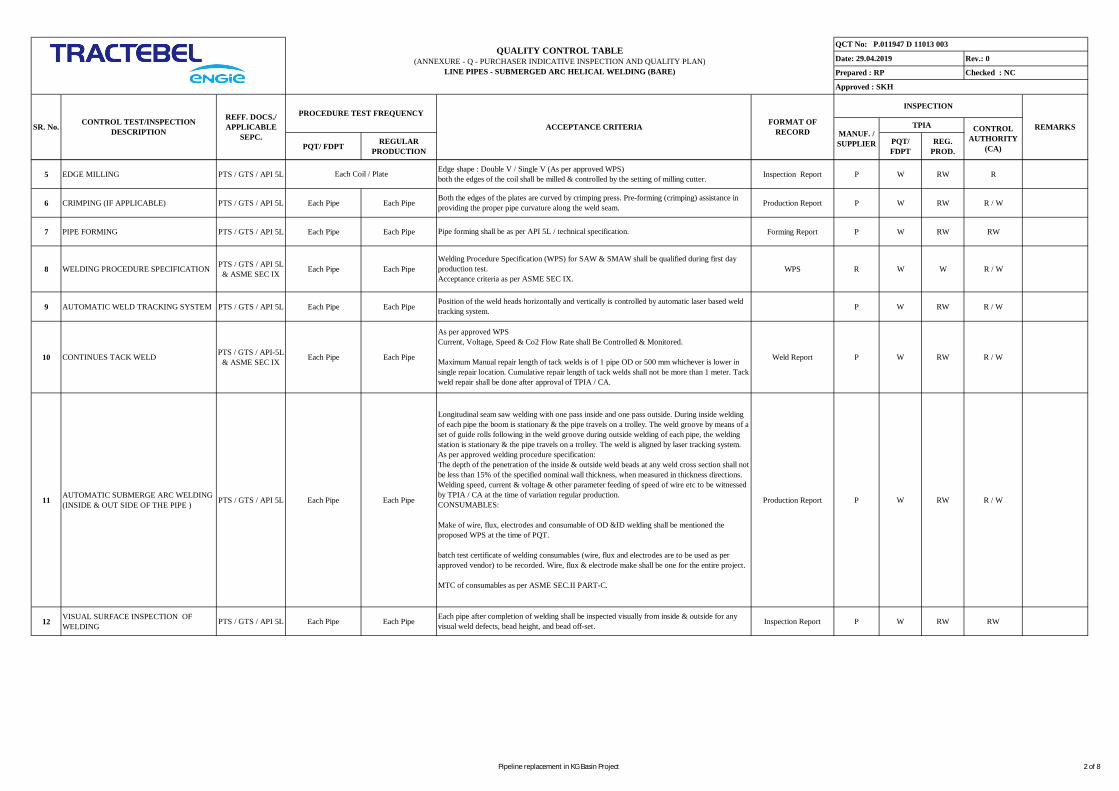
PQT/ FDPT REGULARPRODUCTION
PQT/FDPT
REG.PROD.
Rev.: 0
Checked : NC
QCT No: P.011947 D 11013 003
Date: 29.04.2019
Prepared : RP
Approved : SKH
QUALITY CONTROL TABLE(ANNEXURE - Q - PURCHASER INDICATIVE INSPECTION AND QUALITY PLAN)
LINE PIPES - SUBMERGED ARC HELICAL WELDING (BARE)
INSPECTION
CONTROLAUTHORITY
(CA)
REMARKSTPIACONTROL TEST/INSPECTIONDESCRIPTION
REFF. DOCS./APPLICABLE
SEPC.SR. No. ACCEPTANCE CRITERIA FORMAT OF
RECORD MANUF. /SUPPLIER
PROCEDURE TEST FREQUENCY
5 EDGE MILLING PTS / GTS / API 5L Inspection Report P W RW R
6 CRIMPING (IF APPLICABLE) PTS / GTS / API 5L Each Pipe Each Pipe Production Report P W RW R / W
7 PIPE FORMING PTS / GTS / API 5L Each Pipe Each Pipe Forming Report P W RW RW
8 WELDING PROCEDURE SPECIFICATION PTS / GTS / API 5L& ASME SEC IX Each Pipe Each Pipe WPS R W W R / W
9 AUTOMATIC WELD TRACKING SYSTEM PTS / GTS / API 5L Each Pipe Each Pipe P W RW R / W
10 CONTINUES TACK WELD PTS / GTS / API-5L& ASME SEC IX Each Pipe Each Pipe Weld Report P W RW R / W
11 AUTOMATIC SUBMERGE ARC WELDING(INSIDE & OUT SIDE OF THE PIPE ) PTS / GTS / API 5L Each Pipe Each Pipe Production Report P W RW R / W
12 VISUAL SURFACE INSPECTION OFWELDING PTS / GTS / API 5L Each Pipe Each Pipe Inspection Report P W RW RW
Position of the weld heads horizontally and vertically is controlled by automatic laser based weldtracking system.
As per approved WPSCurrent, Voltage, Speed & Co2 Flow Rate shall Be Controlled & Monitored.
Maximum Manual repair length of tack welds is of 1 pipe OD or 500 mm whichever is lower insingle repair location. Cumulative repair length of tack welds shall not be more than 1 meter. Tackweld repair shall be done after approval of TPIA / CA.
Longitudinal seam saw welding with one pass inside and one pass outside. During inside weldingof each pipe the boom is stationary & the pipe travels on a trolley. The weld groove by means of aset of guide rolls following in the weld groove during outside welding of each pipe, the weldingstation is stationary & the pipe travels on a trolley. The weld is aligned by laser tracking system.As per approved welding procedure specification:The depth of the penetration of the inside & outside weld beads at any weld cross section shall notbe less than 15% of the specified nominal wall thickness, when measured in thickness directions.Welding speed, current & voltage & other parameter feeding of speed of wire etc to be witnessedby TPIA / CA at the time of variation regular production.CONSUMABLES:
Make of wire, flux, electrodes and consumable of OD &ID welding shall be mentioned theproposed WPS at the time of PQT.
batch test certificate of welding consumables (wire, flux and electrodes are to be used as perapproved vendor) to be recorded. Wire, flux & electrode make shall be one for the entire project.
MTC of consumables as per ASME SEC.II PART-C.
Each pipe after completion of welding shall be inspected visually from inside & outside for anyvisual weld defects, bead height, and bead off-set.
Both the edges of the plates are curved by crimping press. Pre-forming (crimping) assistance inproviding the proper pipe curvature along the weld seam.
Pipe forming shall be as per API 5L / technical specification.
Welding Procedure Specification (WPS) for SAW & SMAW shall be qualified during first dayproduction test.Acceptance criteria as per ASME SEC IX.
Each Coil / Plate Edge shape : Double V / Single V (As per approved WPS)both the edges of the coil shall be milled & controlled by the setting of milling cutter.
Pipeline replacement in KG Basin Project 2 of 8

PQT/ FDPT REGULARPRODUCTION
PQT/FDPT
REG.PROD.
Rev.: 0
Checked : NC
QCT No: P.011947 D 11013 003
Date: 29.04.2019
Prepared : RP
Approved : SKH
QUALITY CONTROL TABLE(ANNEXURE - Q - PURCHASER INDICATIVE INSPECTION AND QUALITY PLAN)
LINE PIPES - SUBMERGED ARC HELICAL WELDING (BARE)
INSPECTION
CONTROLAUTHORITY
(CA)
REMARKSTPIACONTROL TEST/INSPECTIONDESCRIPTION
REFF. DOCS./APPLICABLE
SEPC.SR. No. ACCEPTANCE CRITERIA FORMAT OF
RECORD MANUF. /SUPPLIER
PROCEDURE TEST FREQUENCY
15 RESIDUAL STRESS TEST PTS / GTS / API 5L Each PQT Selectedpipe
1 Test at beginning ofeach shift. Test Report P W W W
16 BURST TEST PTS / GTS / API 5LOne pipe for each size,
Grade and thicknessper steel manufacturer
Nil Burst Test Report &Graph P W W H
17 END BEVELLING PTS / GTS / API 5L Both Ends of EachPipe
Both Ends of EachPipe
Dimensional InspectionReport P W RW R / W
14
Welding RectificationReport P13 REPAIR BY SMAW PTS / GTS / API 5L If any If any
All repairs welding shall be performed by the qualified welders in accordance with the approvedwelding procedure specification. Welder qualification test shall be as per API 5L spec.Defect shall be completely removed by grinding and the same shall be confirm with Dye Penetratetest or Magnetic Partical Testing.Repaired welding shall be executed only after specific approval by TPIA / CA for each repair andto be examined by Radiographed & Manual UT.No repairs of weld seam is permissible at pipe ends up to 300 mm or weld one diameter of pipewhichever is more.Max. 3 weld seam repairs per pipe length is allowed.No repairs of repaired location is allowed.Total length of repaired zone on each weld is limited to 3% of total weld length.Distance between two repairs shall not be less than one diameter of pipe or 100 mm whichever ishigher.The weld repairs shall have minimum length of 100mm, even if the defect is of lesser extent.Maximum length of any repair shall be 300mm.An interruption of saw is not considered as a repair unless unacceptable defects are found.Repair welding on parent metal is not permitted.No repair of weld cracks permitted.All repairs shall be carried out befor Cold expansion.Only low hydrogen electrode shall be used.Manual metal arc repair shall be done by minimum 2 passes.
W
W
R / W
R / W
W
–Burst pressure shall be more than minimum rupture pressure on the basis of minimum specifiedUTS as per raw material test certificate.
–Burst pressure & location shall be record
–if burst pipe fail then manufacture shall investigate the root cause & submit the report to theclient before retesting & restarting of the regular production.
Hydrotest Reoprt / ChartRecord / Calibration
Report /Graph
Both end of pipe are machined in accordance with API 5L.Bevel angle 30º to 35º & Root Face 1.6mm ± 0.8mmThickness shall not be less than minimum specified wall thickness.Inside weld Reinforcement shall be removed up to 100MM at both ends of pipes.
Manufactures shall verify with client for special application like AUTOWELDING IN FIELD,Then the BEVEL ANGLE shall as per the confirm from CLIENT.
HYDROTESTING PTS / GTS / API 5L Each Pipe Each Pipe
Each pipe is hydrostatically tested after cold expansion.
Test pressure = 95% of SMYS.Min. Holding time of 15 sec.
PRESSURE GAUGE CALIBRATION:Pressure gauge of min. least count of 2 kg/ cm2 shall be calibrated with a dead weight tester.Accuracy of PG +/- 1% of FSD.FREQUENCY - At the beginning of each shift.
No leakage / burst / deformation on weld and body.No pressure drop on gauge and chart recorder / gragh during holding time.
P W
A ring of 150mm to be cut from one end of 1st pipe of production after Hydro testing. Specimenshall be cut by flame/Sawing parallel to longitudinal axis of pipe at 180 degree from spiral weld.Calculation to be done as specified in cl. 10.2.13 of PTS.
Pipeline replacement in KG Basin Project 3 of 8

PQT/ FDPT REGULARPRODUCTION
PQT/FDPT
REG.PROD.
Rev.: 0
Checked : NC
QCT No: P.011947 D 11013 003
Date: 29.04.2019
Prepared : RP
Approved : SKH
QUALITY CONTROL TABLE(ANNEXURE - Q - PURCHASER INDICATIVE INSPECTION AND QUALITY PLAN)
LINE PIPES - SUBMERGED ARC HELICAL WELDING (BARE)
INSPECTION
CONTROLAUTHORITY
(CA)
REMARKSTPIACONTROL TEST/INSPECTIONDESCRIPTION
REFF. DOCS./APPLICABLE
SEPC.SR. No. ACCEPTANCE CRITERIA FORMAT OF
RECORD MANUF. /SUPPLIER
PROCEDURE TEST FREQUENCY
18 AUT OF WELD SEAM PTS / GTS / API 5L Each Pipe Each Pipe
After hydrotest full length of weld seam is checked in "I-I-X" mode with 45º, 60º and 70º probesin order to detect longitudinal and transverse defect in the weld by a microprocessor basedultrasonic testing system. Weld tracking are applied to autoweld tracking system for correctpositioning of probe with respect to the weld center.
The entire longitudinal edges of hr coils /plates are tested during online UT.
The height of acceptance limit signal in percent of height of the test signals produced by 1.6 mmhole and N5 notch as per API 5L / customer requirement. Any indication greater than the abovereference level will be marked by AUT over pipe surface. all the auto indications shall be crosschecked by manual UT
CALIBRATION STANDARD FOR WELD SEAM:N5 notches & 1.6mm dia. through drill hole for longitudinal and transverse defects
CALIBRATION FREQUENCY:At the beginning of each operation shift and subsequently than in every 4hrs during continuousequipment operation every time the running of system gives rise to doubts on its efficiency.
DECOUPLING CHECKS: Audio Visual Alarm & Paint Marking On Pipe Surface.PERSONNELS: Level II AS PER ASNT'S SNT-TC-1(A) DOC.OR EQ. over all supervision byLevel III.
W R / W
19 MANUAL UT PTS / GTS / API 5L
1) Untested &Suspected area whichis marked By AUT.
2) Both End 250 mmCircumferential
1) Untested &Suspected area whichis marked By AUT.
2) Both End 250 mmCircumferential
Indication by AUT given by angle beam as well as straight beam (TR probe) examinations anduntested areas of pipe end weld (250 mm) shall be cross checked by manual UT by 45°, 60° & 70°angle beam probes and TR probes shall be used for cross checking the corresponding autoindication.
Repaired location shall also be checked by MUT.
Indications confirmed by manual UT shall be re-examined by radiography for their acceptance asper API 5L
CALIBRATION STANDARDSame as those for automatic test
CALIBRATION FREQUENCYAt the beginning of each operation shift and subsequently than in every 4hrs during continuousequipment operation. Every time the running of system gives rise to doubts on its efficiency.
Ultrasonic TestingReport P W
20 X- RAY PTS / GTS / API 5L Entire Length of weld
1) 200 mm of bothends.
2) All Start/Stoppoints of SAW.
3) All MUT confirmed
- Both the ends of each pipe are radiographed for a min. distance of 200 mm.- All intruptions (Start/Stop points) of SAW shall be 100% radiographs.- All MUT confirmed indications.- 5 % of manufactured pipes to be spot radiographs for minimum 200 mm (at least one at themiddle of the pipe (refer note # 9)) selected at random.
Each location radiographed is identified and correlated by the film carrying pipe no, and locationno.
No significant discontinuity in the weld. Sensitivity at least 2% of pipe thickness.
EQUIPMENT & ACCESSORIES: Radiography Test P R
Manual UT Report P W W
R
R / W
R
Pipeline replacement in KG Basin Project 4 of 8

PQT/ FDPT REGULARPRODUCTION
PQT/FDPT
REG.PROD.
Rev.: 0
Checked : NC
QCT No: P.011947 D 11013 003
Date: 29.04.2019
Prepared : RP
Approved : SKH
QUALITY CONTROL TABLE(ANNEXURE - Q - PURCHASER INDICATIVE INSPECTION AND QUALITY PLAN)
LINE PIPES - SUBMERGED ARC HELICAL WELDING (BARE)
INSPECTION
CONTROLAUTHORITY
(CA)
REMARKSTPIACONTROL TEST/INSPECTIONDESCRIPTION
REFF. DOCS./APPLICABLE
SEPC.SR. No. ACCEPTANCE CRITERIA FORMAT OF
RECORD MANUF. /SUPPLIER
PROCEDURE TEST FREQUENCY
21 MAGNETIC PARTICALE INSPECTION PTS / GTS / API 5L Each Pipe Each Pipe MPT Reports P W W R / W
22
A.REVIEW OF SAMPLING PLAN FORPRODUCT TESTING PTS / GTS / API 5L Each Pipe Each Pipe Sampling Plan P R R R
B. CHEMICAL ANALYSIS OF PRODUCT(SPECTRO) PTS / GTS / API 5L 2 Sample / Pipe
2 Sample/ 50 Pipe /Heat
(One at start of heat &One at end of heat of
pipe)
Spectro Analysis Report P R R R
C. TENSILE TEST (Transverse base & weld) PTS / GTS / API 5L
2 set / pipe(set shall consist of 2samples, one for weld& one for body) andone cyclindrical allweld specimen forlongitutinal weld
2 Set / 50 Pipes / Heat/ Size
(set shall consist of 2samples, one for weld
& one for body)
Mechanical Test Report P W W R / W
D. GUIDED BEND TEST PTS / GTS / API 5L
2 sets / Pipes (Set shall consist of 1
Root bend + 1 Facebend)
2 sets / 50 Pipe / Heat (Set shall consist of 1
Root bend + 1 Facebend)
MECHANICAL TESTREPORT P W W R / W
20 X- RAY PTS / GTS / API 5L Seam of PQT pipes indication.
4) In addition to allabove Spotradiography (200 mmmin.)
X- Ray unitFilm - D7 or equivalentWire pentrameter - DIN 62 FE / 6 ISO 12
TECHNIQUE: Single wall single image
X-RAY SOURCE -Vertically downwards/upward placement of penetrameter - film side
CALIBRATION STANDARDS:Wire Penetrameter-DIN 62 FE / 6ISO 12
PERSONNEL: Review of RT films by LEVEL-II qualified inspector.
Report P R
FULL WELD SEAM:- OD of the weld seam of 5 pipes shall be wet magnetic particle tested along it's full length forsurface breaking defect at a frequency of five pipes per shift.
ID / OD WELD SEAM:- upto 300mm weld from each pipe ends from inside & Outside.
BOTH BEVEL END:- Bevel ends of each pipe.
Any imperfections detected on the weld bevel shall cause of re-beveling and the bevel re-inspection by 100% MPI.
Average flux density at ends shall not exceed 20 Gauss.
RESIDUAL MAGNETISM - max. 20 Gauss. (Avg. of 4 reading), no individual reading shallexceed 25 gauss.
PRODUCT TESTING
The specimena) Shall not fracture completely.b) Shall not revel any cracks or rupture in the weld metal greater than 3.2 mm length regardless ofdepthc) Shall not reveal any any cracks or rupture in the parent metal, HAZ or fusion line longer than3.20 mm or deeper than 12.5% of specified w. thick except cracks that occur at the edges of thespecimen and that are less than 6.40 mm long.
R R
CHEMICAL PROPERTIES
For Grade X70, % Element required shall be as per PTS.
MECHANICAL PROPERTIES
For Grade X 70YS = 485 MPa, UTS = 570 Mpa
YS/UTS = 0.90 MAX% EL = 25 % MIN.
Pipeline replacement in KG Basin Project 5 of 8
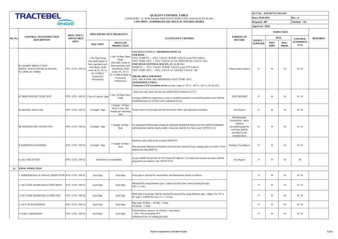
PQT/ FDPT REGULARPRODUCTION
PQT/FDPT
REG.PROD.
Rev.: 0
Checked : NC
QCT No: P.011947 D 11013 003
Date: 29.04.2019
Prepared : RP
Approved : SKH
QUALITY CONTROL TABLE(ANNEXURE - Q - PURCHASER INDICATIVE INSPECTION AND QUALITY PLAN)
LINE PIPES - SUBMERGED ARC HELICAL WELDING (BARE)
INSPECTION
CONTROLAUTHORITY
(CA)
REMARKSTPIACONTROL TEST/INSPECTIONDESCRIPTION
REFF. DOCS./APPLICABLE
SEPC.SR. No. ACCEPTANCE CRITERIA FORMAT OF
RECORD MANUF. /SUPPLIER
PROCEDURE TEST FREQUENCY
E. CHARPY IMPACT TEST(BODY, WELD CENTRE & HAZ (FL,FL+2MM, FL+5MM))
PTS / GTS / API 5L
1 Set /Pipe/Temp(Set shall consist ofthree specimen each
from Body, Weldcenter & FL, FL+2,
FL+5 MM inTranseverdOrientation)
1 Set/ 50 Pipe/ Heat/Temp.
(Set shall consist ofthree specimen each
from Body, Weldcenter, FL, FL+2,
FL+5 MM & Body inTranseverdOrientation)
Charpy Impact Report P W W R / W
F. DROP WEIGHT TEAR TEST PTS / GTS / API 5L 1 Set of 2 pieces / pipe 1 Set / 50 Pipe/ Heat/Temp TEST REPORT P W W R / W
G. MACRO ANALYSIS PTS / GTS / API 5L 6 Sample / Pipe
1 Sample / 50 Pipe/Heat or min. One
Sample per operatingshift
Test Report P W W R / W
H. MICROSCOPIC ANANLYSIS PTS / GTS / API 5L 6 Sample / Pipe 1 Sample/ 50 Pipe /Heat
MetallographicExamination report
(Opticalmicrophotograph for
each heat shall beprovided by themanufacturer)
P W W R / W
I. HARDNESS (VICKERS) PTS / GTS / API 5L 2 Sample / Pipe 1 Sample/ 50 Pipe /Heat Hardness Test Report P W W R / W
J. ALL WELD TEST PTS / GTS / API 5L Test Report P W W W
23
1. DIMENSIONAL & VISUAL INSPECTION PTS / GTS / API 5L Each Pipe Each Pipe P W W R / W
2. OUT SIDE DIAMETER AT PIPE BODY PTS / GTS / API 5L Each Pipe Each Pipe P W W R / W
3. OUT SIDE DIAMETER AT PIPE END PTS / GTS / API 5L Each Pipe Each Pipe P W W R / W
4. OUT OF ROUNDNESS PTS / GTS / API 5L Each Pipe Each Pipe P W W R / W
5. WALL THICKNESS PTS / GTS / API 5L Each Pipe Each Pipe P W W R / W
Pipe ends: ID Max. - ID Min. < 3mmFor Body - < 5mm
Hardness value shall not be exceeds 248 HV10
The maximum difference in hardness between base material & any reading taken on weld or HAZshall be less than 80HV10.
- shear area avg. shear fracture area shall be 85% minimum at 0 °C.
(testing at different temperature is only to establish transition curve) full transition curve shall beestablished heat out of three with a minimum of one.
Proper fusion of each layer and free from liner defect and importance inclusion
No untempered Martensite remains & uniformly distributed ferrite structure shall be establishedand fusion line shall be clearly visible. Grain size shall be 8 or finer as per ASTM E 112
Each pipe is checked for visual defect and dimensional checks as follows
Measured by using diameter tape / calipers location 2mtr. interval along the pipe.OD +/- 3 mm.
Both ends of each pipe shall be checked & measured by using diameter tape / caliper. For 16" to20" pipe + 0.005D but max of +/- 1.6 mm.
Wall thickness measure by d-meter / micrometer+ 10%, -0% of nomimal W.T(minimum 8 nos. of reading per pipe)
Each batch of consumable. As per ASME Section-IIC & GTS Annex.B Table B.1. A round cross-section test piece shall beprepared in accordance with ASTM A370.
FINAL INSPECTION
ABSORBED ENERGY, MINIMUM (NOTE 11)FOR BASE :TEST TEMP 0°C , - AVG. VALUE & INDI. VALUE as per PTS Table GTEST TEMP -20°C , - AVG. VALUE=35 J & INDIVIDUAL VALUE =28 JFOR WELD CENTER & HAZ (FL, FL+2, FL+5) :TEMP 0°C , - AVG. VALUE & INDI. VALUE as per PTS Table GTEST TEMP -20°C , - AVG. VALUE=35 J & INDI. VALUE= 28J
SHEAR AREA FOR BODY:AVG. 90% & INDI. 80% MINIMUM at TEST TEMP -20°C,TRANSITION CURVE :Transverse CVN transition curves at temp. range of -50 °C, -40 °C, -20 °C, 0°C & 10°C.
Pipeline replacement in KG Basin Project 6 of 8
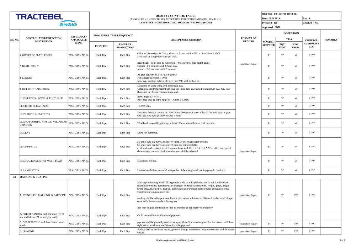
PQT/ FDPT REGULARPRODUCTION
PQT/FDPT
REG.PROD.
Rev.: 0
Checked : NC
QCT No: P.011947 D 11013 003
Date: 29.04.2019
Prepared : RP
Approved : SKH
QUALITY CONTROL TABLE(ANNEXURE - Q - PURCHASER INDICATIVE INSPECTION AND QUALITY PLAN)
LINE PIPES - SUBMERGED ARC HELICAL WELDING (BARE)
INSPECTION
CONTROLAUTHORITY
(CA)
REMARKSTPIACONTROL TEST/INSPECTIONDESCRIPTION
REFF. DOCS./APPLICABLE
SEPC.SR. No. ACCEPTANCE CRITERIA FORMAT OF
RECORD MANUF. /SUPPLIER
PROCEDURE TEST FREQUENCY
6. OFFSET OF PLATE EDGES PTS / GTS / API 5L Each Pipe Each Pipe P W W R / W
7. BEAD HEIGHT PTS / GTS / API 5L Each Pipe Each Pipe P W W R / W
8. LENGTH PTS / GTS / API 5L Each Pipe Each Pipe P W W R / W
9. OUT OF STRAIGHTNESS PTS / GTS / API 5L Each Pipe Each Pipe P W W R / W
10. PIPE ENDS / BEVEL & ROOT FACE PTS / GTS / API 5L Each Pipe Each Pipe P W W R / W
11. OUT OF SQUARENESS PTS / GTS / API 5L Each Pipe Each Pipe P W W R / W
12. PEAKING & FLATNESS PTS / GTS / API 5L Each Pipe Each Pipe P W W R / W
13. END FLUSHING / INSIDE WELD BEADGRINDING PTS / GTS / API 5L Each Pipe Each Pipe P W W R / W
14. DENT PTS / GTS / API 5L Each Pipe Each Pipe P W W R / W
15. UNDERCUT PTS / GTS / API 5L Each Pipe Each Pipe P W W R / W
16. MISALIGNMENT OF WELD BEAD PTS / GTS / API 5L Each Pipe Each Pipe P W W R / W
17. LAMINATION PTS / GTS / API 5L Each Pipe Each Pipe P W W R / W
24
A. STENCILING MARKING & BARCODE PTS / GTS / API 5L Each Pipe Each Pipe Inspection Report P W RW R / W
B. COLOR BAND for each thickness (Of 50mm width from 150 mm of pipe ends). PTS / GTS / API 5L Each Pipe Each Pipe
C. DIE STAMPING with Low Stress dottedpunch. PTS / GTS / API 5L Each Pipe Each Pipe Inspection Report P W RW R / W
D. COATING PTS / GTS / API 5L Each Pipe Each Pipe Inspection Report P W RW R / W
Measured by using string with steel scale max.Total deviation from straight line over the entire pipe length shall be maximum 12.0 mm. Lessthan 4mm in 1 Meter from each pipe end.
Offset of plate edges for Thk < 15mm : 1.5 mm, and for Thk > 15 to 25mm 0.1WTMeasured by gauge three time per shift.
Bead height (inside pipe & outside pipe) Measured by bead height gauge.Outside - 0.5 mm min. and 3.2 mm max.Inside - 0.5 mm min. and 2.5 mm max.
All pipe between 11.5 to 12.5 m (max.)For Sample pipes min. 11.0 mMin. avg. length of entire order qty. (per WT) shall be 12.0 m.
Bevel angle 30º to 35º ,Root face shall be in the range of 1.6 mm ± 0.8mm
1.5 mm Max.
Of 50 mm width from 150 mm of pipe ends.
MARKING & COATING
Marking conforming to API 5L Appendix it will be in English sing metric unit it will includemanufacturer name, nominal outside diameter, nominal wall thickness, weight, grade, length,hydro pressure, pipe no., heat no., acceptance no. purchaser name process of manufacturingsupplementary requirements etc.
marking shall be white pen stencil to the pipe axis at a distance of 300mm from both end of pipe(one inside & one outside at 90 degree).
Bar code on pipe identification shall be provided as per approved procedure.
pipe no. shall be placed by cold die stamping (Low Stress dotted punch) at the distance of 50mmright side of weld seam and 50mm from the pipe end.
Surface shall be free from any oil, grease & foreign material etc., only marked area shall be varnishcoated.
Deviation from the circular arc of 0.25D or 200mm whichever is less at the weld seam at pipeends and pipe body shall not exceed 1.6mm.
Weld bead removal by grinding: at least 100mm internally from both the ends.
Dents not permitted.
a.) under cuts that have a depth < 0.4 mm are acceptable after dressingb.) under cuts that have a depth > 0.4mm are not acceptable.c) all such undercuts are treated in accordance with Cl. C.2 & C3 of API 5L. After removal ofthese defects minimum thickness tolerances shall be achieved.
Lamination shall not accepted irrespective of their length and size in pipe end / bevel end
Inspection Report
Maximum. 3.0 mm.
Inspection Report
Pipeline replacement in KG Basin Project 7 of 8

PQT/ FDPT REGULARPRODUCTION
PQT/FDPT
REG.PROD.
Rev.: 0
Checked : NC
QCT No: P.011947 D 11013 003
Date: 29.04.2019
Prepared : RP
Approved : SKH
QUALITY CONTROL TABLE(ANNEXURE - Q - PURCHASER INDICATIVE INSPECTION AND QUALITY PLAN)
LINE PIPES - SUBMERGED ARC HELICAL WELDING (BARE)
INSPECTION
CONTROLAUTHORITY
(CA)
REMARKSTPIACONTROL TEST/INSPECTIONDESCRIPTION
REFF. DOCS./APPLICABLE
SEPC.SR. No. ACCEPTANCE CRITERIA FORMAT OF
RECORD MANUF. /SUPPLIER
PROCEDURE TEST FREQUENCY
E. BEVEL PROTECTORS PTS / GTS / API 5L Each Pipe Each Pipe Inspection Report P W RW R / W
25
RECORD OF WELDING PARAMETER &MILL START & STOPAGE, SPEED,BREAKDOWN & POWER FAILURE
PTS / GTS / API 5L Each Pipe Each Pipe Owner DPR Format P R / W
26
A. QAP / PO / MTC / IR / COMPLIANCECERTIFICATES PTS / GTS / API 5L Each Dispatched Pipe Each Dispatched Pipe Compliance Certificate
3.2 P R
B. INSPECTION RELEASE NOTE PTS / GTS / API 5L Each Dispatched Pipe Each Dispatched Pipe Compliance Certificate H R
27
PIPE LOADING PTS / GTS / API 5L ---- ---- Dispatch Sheet P M M -
Legend:
NOTE:
FINAL DISPATCH
As per GTS/PTS & Approved Procedure.
P-PERFORM, R-REVIEW, W-WITNESS, RW - RANDOM 10% WITNESS, H-HOLD, M- MONITOR, TPIA-THIRD PARTY INSPECTION AGENCY, CA - CONTROL AUTHORITY (Owner/Engineer or their Authorised Inspection Agency)
1. Material & type shall be as per tender specs including all amendments & clarification till the date of First Day Production.
DAILY PROGRESS REPORT
DPR & Rolling Report
FINAL DOCUMENTS
AS PER PTS/GTS & QCT
As per EN 10204 3.2 Certification
Hold point = No further steps may be undertaken before the intervention of the appointed responsible takes place.
Witness point = The appointed responsible has to be notified of the operation in advance, but production will continue whether the intervention took place or not.
H
R
H
2. Certification requirements to comply with EN 10204 - 3.2 certificate to be issues by TPIA.3. All measuring instrument shall have valid calibration certificates and no such instrument / equipment be used when there is no valid calibration.4. TPIA has to witness and sign the process parameters per shift (as recommended sheet) & to send with DPR on daily basis to CLIENT/ CONSULTANT.5. MPS, NDT etc. procedure shall be reviewed & approved by CLIENT/ CONSULTANT in line with tender specification, pre bid reply & approved QAP.6. When external coating is not applied for more than 30 days, necessary rust preventing paint to be applied.7. In case of bare pipe supply rust preventing paint of 100 micron shall be applied .8. In case of any variation in QAP and the technical specification, the most stringent requirement shall be complied.
10. All clause of API 5L 45th edition and tests should be followed scrupulously. Only the clause of present PTS/GTS which are more stringent or supplementary to the API 5L - 45th edition new edition will prevail.9. TPIA shall select the weld length for X-Ray to fulfill 5% of manufactured pipe requirements, in such a way that it should cover each heat as well as each shift.
Metallic end protector with high impact bevel protection shall be provided at both ends.
Pipeline replacement in KG Basin Project 8 of 8
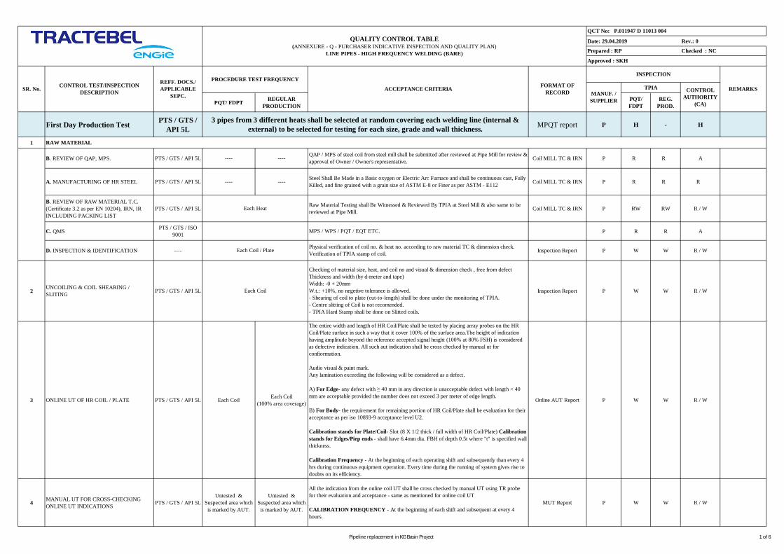
Date: 29.04.2019 Rev.: 0
PQT/ FDPT REGULARPRODUCTION
PQT/FDPT
REG.PROD.
First Day Production Test PTS / GTS /API 5L MPQT report P H - H
1
B. REVIEW OF QAP, MPS. PTS / GTS / API 5L ---- ---- Coil MILL TC & IRN P R R A
A. MANUFACTURING OF HR STEEL PTS / GTS / API 5L ---- ---- Coil MILL TC & IRN P R R R
B. REVIEW OF RAW MATERIAL T.C.(Certificate 3.2 as per EN 10204), IRN, IRINCLUDING PACKING LIST
PTS / GTS / API 5L Coil MILL TC & IRN P RW RW R / W
C. QMS PTS / GTS / ISO9001 P R R A
D. INSPECTION & IDENTIFICATION ---- Inspection Report P W W R / W
2 UNCOILING & COIL SHEARING /SLITING PTS / GTS / API 5L Inspection Report P W W R / W
3 ONLINE UT OF HR COIL / PLATE PTS / GTS / API 5L Each Coil Each Coil(100% area coverage) Online AUT Report P W W R / W
4 MANUAL UT FOR CROSS-CHECKINGONLINE UT INDICATIONS PTS / GTS / API 5L
Untested &Suspected area whichis marked by AUT.
Untested &Suspected area whichis marked by AUT.
MUT Report P W W R / W
QUALITY CONTROL TABLE(ANNEXURE - Q - PURCHASER INDICATIVE INSPECTION AND QUALITY PLAN)
LINE PIPES - HIGH FREQUENCY WELDING (BARE)
QCT No: P.011947 D 11013 004
Checked : NC
Approved : SKH
Prepared : RP
3 pipes from 3 different heats shall be selected at random covering each welding line (internal &external) to be selected for testing for each size, grade and wall thickness.
INSPECTION
CONTROLAUTHORITY
(CA)
REMARKSTPIA
All the indication from the online coil UT shall be cross checked by manual UT using TR probefor their evaluation and acceptance - same as mentioned for online coil UT
CALIBRATION FREQUENCY - At the beginning of each shift and subsequent at every 4hours.
Each Coil
Checking of material size, heat, and coil no and visual & dimension check , free from defectThickness and width (by d-meter and tape)Width: -0 + 20mmW.t.: +10%, no negetive tolerance is allowed.- Shearing of coil to plate (cut-to-length) shall be done under the monitoring of TPIA.- Centre slitting of Coil is not recomended.- TPIA Hard Stamp shall be done on Slitted coils.
The entire width and length of HR Coil/Plate shall be tested by placing array probes on the HRCoil/Plate surface in such a way that it cover 100% of the surface area.The height of indicationhaving amplitude beyond the reference accepted signal height (100% at 80% FSH) is consideredas defective indication. All such aut indication shall be cross checked by manual ut forconfiormation.
Audio visual & paint mark.Any lamination exceeding the following will be considered as a defect.
A) For Edge- any defect with ≥ 40 mm in any direction is unacceptable defect with length < 40mm are acceptable provided the number does not exceed 3 per meter of edge length.
B) For Body- the requirement for remaining portion of HR Coil/Plate shall be evaluation for theiracceptance as per iso 10893-9 acceptance level U2.
Calibration stands for Plate/Coil- Slot (8 X 1/2 thick / full width of HR Coil/Plate) Calibrationstands for Edges/Piep ends - shall have 6.4mm dia. FBH of depth 0.5t where "t" is specified wallthickness.
Calibration Frequency - At the beginning of each operating shift and subsequently than every 4hrs during continuous equipment operation. Every time during the running of system gives rise todoubts on its efficiency.
CONTROL TEST/INSPECTIONDESCRIPTION
REFF. DOCS./APPLICABLE
SEPC.SR. No. ACCEPTANCE CRITERIA FORMAT OF
RECORD MANUF. /SUPPLIER
PROCEDURE TEST FREQUENCY
Each Heat
Each Coil / Plate
Steel Shall Be Made in a Basic oxygen or Electric Arc Furnace and shall be continuous cast, FullyKilled, and fine grained with a grain size of ASTM E-8 or Finer as per ASTM - E112
RAW MATERIAL
QAP / MPS of steel coil from steel mill shall be submitted after reviewed at Pipe Mill for review &approval of Owner / Owner's representative.
Raw Material Testing shall Be Witnessed & Reviewed By TPIA at Steel Mill & also same to bereviewed at Pipe Mill.
MPS / WPS / PQT / EQT ETC.
Physical verification of coil no. & heat no. according to raw material TC & dimension check.Verification of TPIA stamp of coil.
Pipeline replacement in KG Basin Project 1 of 6

Date: 29.04.2019 Rev.: 0
PQT/ FDPT REGULARPRODUCTION
PQT/FDPT
REG.PROD.
QUALITY CONTROL TABLE(ANNEXURE - Q - PURCHASER INDICATIVE INSPECTION AND QUALITY PLAN)
LINE PIPES - HIGH FREQUENCY WELDING (BARE)
QCT No: P.011947 D 11013 004
Checked : NC
Approved : SKH
Prepared : RP
INSPECTION
CONTROLAUTHORITY
(CA)
REMARKSTPIACONTROL TEST/INSPECTIONDESCRIPTION
REFF. DOCS./APPLICABLE
SEPC.SR. No. ACCEPTANCE CRITERIA FORMAT OF
RECORD MANUF. /SUPPLIER
PROCEDURE TEST FREQUENCY
5 PIPE FORMING PTS / GTS / API 5L Each Pipe Each Pipe FORMING REPORT P W RW R / W
6 WELDING PARAMETERS PTS / GTS / API 5L& ASME SEC IX Each Pipe Each Pipe WPS R W W R / W
7 SEAM NORMALIZING PTS / GTS / API 5L Each Pipe Each Pipe Heat Treatment report P W RW R / W
8 FLATTENING TEST PTS / GTS / API 5L 2 sets / Pipes Each Coil Test Report P W W R / W
9 VISUAL SURFACE INSPECTION PTS / GTS / API 5L Each Pipe Each Pipe Inspection Report P W RW RW
11 BURST TEST PTS / GTS / API 5LOne pipe for each size,
Grade and thicknessper steel manufacturer
Nil Burst Test Report &Graph P W W H
12 END BEVELLING PTS / GTS / API 5L Both Ends of EachPipe
Both Ends of EachPipe
Dimensional InspectionReport P W RW R / W
4 Samples per coil (2 samples each from 1st & last accepted pipes of the coil). Falttening will bedone at 0° & 90°. In case of weld stop, a sample from each crop end shall be tested at 90°.Acceptance as per cl. no. 9.6 of PTS & API 5L
1. No opening in weld at distance 50% of OD.2. No Opening in material at distance 33% of OD.3. No Lamination or Burnt metal in material at full flattening.
As per approved procedure.
As per approved procedure.
Each pipe after completion of welding shall be inspected visually from inside & outside for anyvisual weld defects, bead height, and bead off-set.
Following Welding Parameters be qualified during first day production test.a. Temperature; b. Frequency; c. Current; d. Voltage; e. SpeedAcceptance criteria as per ASME SEC IX.
10 HYDROTESTING PTS / GTS / API 5L Each Pipe Each Pipe
Each pipe is hydrostatically tested.
Test pressure = 95% of SMYS.Min. Holding time of 15 sec.
PRESSURE GAUGE CALIBRATION:Pressure gauge of min. least count of 2 kg/ cm2 shall be calibrated with a dead weight tester.Accuracy of PG +/- 1% of FSD.FREQUENCY - At the beginning of each working shift.
No leakage / burst / deformation on weld and body.No pressure drop on gauge and chart recorder / gragh during holding time.
W W R / W
–Burst pressure shall be more than minimum rupture pressure on the basis of minimum specifiedUTS as per raw material test certificate.
–Burst pressure & location shall be record
–if burst pipe fail then manufacture shall investigate the root cause & submit the report to theclient before retesting & restarting of the regular production.
Hydrotest Reoprt / ChartRecord / Calibration
Report /Graph
Both end of pipe are machined in accordance with API 5L.Bevel angle 30º to 35º & Root Face 1.6mm ± 0.8mmThickness shall not be less than minimum specified wall thickness.Inside weld Reinforcement shall be removed up to 100MM at both ends of pipes.
Manufactures shall verify with client for special application like AUTOWELDING IN FIELD,Then the BEVEL ANGLE shall as per the confirmation from CLIENT.
P
Pipeline replacement in KG Basin Project 2 of 6

Date: 29.04.2019 Rev.: 0
PQT/ FDPT REGULARPRODUCTION
PQT/FDPT
REG.PROD.
QUALITY CONTROL TABLE(ANNEXURE - Q - PURCHASER INDICATIVE INSPECTION AND QUALITY PLAN)
LINE PIPES - HIGH FREQUENCY WELDING (BARE)
QCT No: P.011947 D 11013 004
Checked : NC
Approved : SKH
Prepared : RP
INSPECTION
CONTROLAUTHORITY
(CA)
REMARKSTPIACONTROL TEST/INSPECTIONDESCRIPTION
REFF. DOCS./APPLICABLE
SEPC.SR. No. ACCEPTANCE CRITERIA FORMAT OF
RECORD MANUF. /SUPPLIER
PROCEDURE TEST FREQUENCY
15 MAGNETIC PARTICALE INSPECTION PTS / GTS / API 5L Each Pipe Each Pipe MPT Reports P W W R / W
16
A.REVIEW OF SAMPLING PLAN FORPRODUCT TESTING PTS / GTS / API 5L Each Pipe Each Pipe Sampling Plan P R R R
13 AUT OF WELD SEAM PTS / GTS / API 5L Each Pipe Each Pipe
After hydrotest full length of weld seam is checked in "I-I-X" mode with 45º, 60º & 70º probes inorder to detect longitudinal and transverse defect in the weld by a microprocessor based ultrasonictesting system. Weld seam tracking are applied to autoweld (Laser) tracking system for correctpositioning of probe with respect to the weld center.
The entire longitudinal edges of hr coils /plates are tested during online UT.
The height of acceptance limit signal in percent of height of the test signals produced by 1.6 mmhole and N5 notch as per API 5L / customer requirement. Any indication greater than the abovereference level will be marked by AUT over pipe surface. all the auto indications shall be crosschecked by manual UT
CALIBRATION STANDARD FOR WELD SEAM:N5 notches and 1.6mm dia. through drill hole for longitudinal and transverse defects
CALIBRATION FREQUENCY:At the beginning of each operation shift and subsequently than in every 4hrs during continuousequipment operation every time the running of system gives rise to doubts on its efficiency.
DECOUPLING CHECKS: Audio Visual Alarm & Paint Marking On Pipe Surface.PERSONNELS: Level II AS PER ASNT'S SNT-TC-1(A) DOC.OR EQ. over all supervision byLevel III.
W R / W
14 MANUAL UT PTS / GTS / API 5L
1) Untested &Suspected area whichis marked By AUT.
2) Both End 250 mmCircumferential
1) Untested &Suspected area whichis marked By AUT.
2) Both End 250 mmCircumferential
Indication by AUT given by angle beam as well as straight beam (TR probe) examinations anduntested areas of pipe end weld (250 mm) shall be cross checked by manual UT by 45°, 60° & 70°angle beam probes and TR probes shall be used for cross checking the corresponding autoindication.
Repaired location shall also be checked by MUT.
Indications confirmed by manual UT shall be re-examined by radiography for their acceptance asper API 5L.
CALIBRATION STANDARDSame as those for automatic test
CALIBRATION FREQUENCYAt the beginning of each operation shift and subsequently than in every 4hrs during continuousequipment operation. Every time the running of system gives rise to doubts on its efficiency.
Ultrasonic TestingReport P W
Manual UT Report P W W R / W
BOTH BEVEL END:- Bevel ends of each pipe.
Any imperfections detected on the weld bevel shall cause of re-beveling and the bevel re-inspection by 100% MPI.
Average flux density at ends shall not exceed 20 Gauss.
RESIDUAL MAGNETISM - max. 20 Gauss. (Avg. of 4 reading), no individual reading shallexceed 25 gauss.
PRODUCT TESTING
Pipeline replacement in KG Basin Project 3 of 6
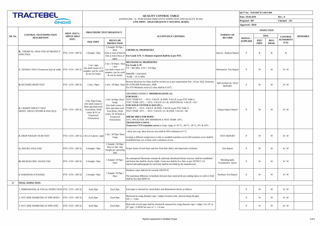
Date: 29.04.2019 Rev.: 0
PQT/ FDPT REGULARPRODUCTION
PQT/FDPT
REG.PROD.
QUALITY CONTROL TABLE(ANNEXURE - Q - PURCHASER INDICATIVE INSPECTION AND QUALITY PLAN)
LINE PIPES - HIGH FREQUENCY WELDING (BARE)
QCT No: P.011947 D 11013 004
Checked : NC
Approved : SKH
Prepared : RP
INSPECTION
CONTROLAUTHORITY
(CA)
REMARKSTPIACONTROL TEST/INSPECTIONDESCRIPTION
REFF. DOCS./APPLICABLE
SEPC.SR. No. ACCEPTANCE CRITERIA FORMAT OF
RECORD MANUF. /SUPPLIER
PROCEDURE TEST FREQUENCY
B. CHEMICAL ANALYSIS OF PRODUCT(SPECTRO) PTS / GTS / API 5L 2 Sample / Pipe
2 Sample/ 50 Pipe /Heat
(One at start of heat &One at end of heat of
pipe)
Spectro Analysis Report P R R R
C. TENSILE TEST (Transverse base & weld) PTS / GTS / API 5L
2 set / pipe(set shall consist of 2samples, one for weld
& one for body)
2 Set / 50 Pipes / Heat/ Size
(set shall consist of 2samples, one for weld
& one for body)
Mechanical Test Report P W W R / W
D. REVERSE BEND TEST PTS / GTS / API 5L 2 sets / Pipes 2 sets / 50 Pipe / Heat MECHANICAL TESTREPORT P W W R / W
E. CHARPY IMPACT TEST(BODY, WELD CENTRE & HAZ (FL)) PTS / GTS / API 5L
2 Set /Pipe/Temp(Set shall consist ofthree specimen each
from Body, Weldcenter & FL in
TranseverdOrientation)
1 Set/ 50 Pipe/ Heat/Temp.
(Set shall consist ofthree specimen each
from Body, Weldcenter, FL & Body in
TranseverdOrientation)
Charpy Impact Report P W W R / W
F. DROP WEIGHT TEAR TEST PTS / GTS / API 5L 2 Set of 2 pieces / pipe 1 Set / 50 Pipe/ Heat/Temp TEST REPORT P W W R / W
G. MACRO ANALYSIS PTS / GTS / API 5L 6 Sample / Pipe
1 Sample / 50 Pipe/Heat or min. One
Sample per operatingshift
Test Report P W W R / W
H. MICROSCOPIC ANANLYSIS PTS / GTS / API 5L 6 Sample / Pipe 1 Sample/ 50 Pipe /Heat
MetallographicExamination report P W W R / W
I. HARDNESS (VICKERS) PTS / GTS / API 5L 2 Sample / Pipe 1 Sample/ 50 Pipe /Heat Hardness Test Report P W W R / W
17
1. DIMENSIONAL & VISUAL INSPECTION PTS / GTS / API 5L Each Pipe Each Pipe P W W R / W
2. OUT SIDE DIAMETER AT PIPE BODY PTS / GTS / API 5L Each Pipe Each Pipe P W W R / W
3. OUT SIDE DIAMETER AT PIPE END PTS / GTS / API 5L Each Pipe Each Pipe P W W R / W
Hardness value shall not be exceeds 248 HV10
The maximum difference in hardness between base material & any reading taken on weld or HAZshall be less than 80HV10.
- shear area avg. shear fracture area shall be 85% minimum at 0 °C.
(testing at different temperature is only to establish transition curve) full transition curve shall beestablished heat out of three with a minimum of one.
Reverse Bend test for Pipes shall be carried out as per requirements Part –II [sec 3(i)], AnnexureIII of PNGRB Notification, 2008.For X70 Minimum strain (e) value shall be 0.1075.
FINAL INSPECTION
CHEMICAL PROPERTIES
For Grade X70, % Element required shall be as per PTS.
MECHANICAL PROPERTIESFor Grade X 70YS = 485 MPa, UTS = 570 Mpa
YS/UTS = 0.90 MAX% EL = 25 % MIN.
ABSORBED ENERGY, MINIMUM (NOTE 11)FOR BASE :TEST TEMP 0°C , - AVG. VALUE & INDI. VALUE as per PTS Table GTEST TEMP -20°C , - AVG. VALUE=35 J & INDIVIDUAL VALUE =28 JFOR WELD CENTER & HAZ (FL) :TEMP 0°C , - AVG. VALUE & INDI. VALUE as per PTS Table GTEST TEMP -20°C , - AVG. VALUE=35 J & INDI. VALUE= 28J
SHEAR AREA FOR BODY:AVG. 90% & INDI. 80% MINIMUM at TEST TEMP -20°C,TRANSITION CURVE :Transverse CVN transition curves at temp. range of -50 °C, -40 °C, -20 °C, 0°C & 10°C.
Proper fusion of each layer and free from liner defect and importance inclusion
No untempered Martensite remains & uniformly distributed ferrite structure shall be establishedand fusion line shall be clearly visible. Grain size shall be 8 or finer as per ASTM E 112.Optical microphotograph for each heat shall be provided by the manufacturer.
Each pipe is checked for visual defect and dimensional checks as follows
Measured by using diameter tape / calipers location 2mtr. interval along the pipe.OD +/- 3 mm.
Both ends of each pipe shall be checked & measured by using diameter tape / caliper. For 16" to20" pipe + 0.005D but max of +/- 1.6 mm.
Pipeline replacement in KG Basin Project 4 of 6
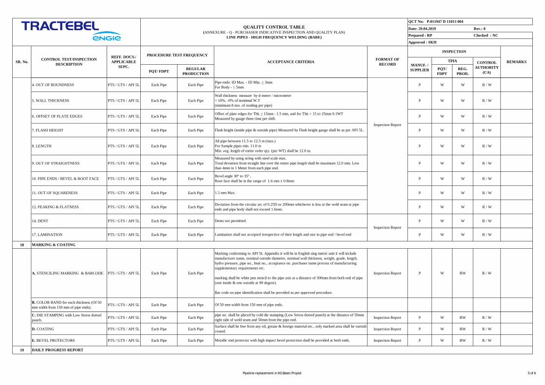
Date: 29.04.2019 Rev.: 0
PQT/ FDPT REGULARPRODUCTION
PQT/FDPT
REG.PROD.
QUALITY CONTROL TABLE(ANNEXURE - Q - PURCHASER INDICATIVE INSPECTION AND QUALITY PLAN)
LINE PIPES - HIGH FREQUENCY WELDING (BARE)
QCT No: P.011947 D 11013 004
Checked : NC
Approved : SKH
Prepared : RP
INSPECTION
CONTROLAUTHORITY
(CA)
REMARKSTPIACONTROL TEST/INSPECTIONDESCRIPTION
REFF. DOCS./APPLICABLE
SEPC.SR. No. ACCEPTANCE CRITERIA FORMAT OF
RECORD MANUF. /SUPPLIER
PROCEDURE TEST FREQUENCY
4. OUT OF ROUNDNESS PTS / GTS / API 5L Each Pipe Each Pipe P W W R / W
5. WALL THICKNESS PTS / GTS / API 5L Each Pipe Each Pipe P W W R / W
6. OFFSET OF PLATE EDGES PTS / GTS / API 5L Each Pipe Each Pipe P W W R / W
7. FLASH HEIGHT PTS / GTS / API 5L Each Pipe Each Pipe P W W R / W
8. LENGTH PTS / GTS / API 5L Each Pipe Each Pipe P W W R / W
9. OUT OF STRAIGHTNESS PTS / GTS / API 5L Each Pipe Each Pipe P W W R / W
10. PIPE ENDS / BEVEL & ROOT FACE PTS / GTS / API 5L Each Pipe Each Pipe P W W R / W
11. OUT OF SQUARENESS PTS / GTS / API 5L Each Pipe Each Pipe P W W R / W
12. PEAKING & FLATNESS PTS / GTS / API 5L Each Pipe Each Pipe P W W R / W
14. DENT PTS / GTS / API 5L Each Pipe Each Pipe P W W R / W
17. LAMINATION PTS / GTS / API 5L Each Pipe Each Pipe P W W R / W
18
A. STENCILING MARKING & BARCODE PTS / GTS / API 5L Each Pipe Each Pipe Inspection Report P W RW R / W
B. COLOR BAND for each thickness (Of 50mm width from 150 mm of pipe ends). PTS / GTS / API 5L Each Pipe Each Pipe
C. DIE STAMPING with Low Stress dottedpunch. PTS / GTS / API 5L Each Pipe Each Pipe Inspection Report P W RW R / W
D. COATING PTS / GTS / API 5L Each Pipe Each Pipe Inspection Report P W RW R / W
E. BEVEL PROTECTORS PTS / GTS / API 5L Each Pipe Each Pipe Inspection Report P W RW R / W
19
Offset of plate edges for Thk < 15mm : 1.5 mm, and for Thk > 15 to 25mm 0.1WTMeasured by gauge three time per shift.
Flash height (inside pipe & outside pipe) Measured by Flash height gauge shall be as per API 5L.
All pipe between 11.5 to 12.5 m (max.)For Sample pipes min. 11.0 mMin. avg. length of entire order qty. (per WT) shall be 12.0 m.
Bevel angle 30º to 35º ,Root face shall be in the range of 1.6 mm ± 0.8mm
1.5 mm Max.
Pipe ends: ID Max. - ID Min. < 3mmFor Body - < 5mm
Measured by using string with steel scale max.Total deviation from straight line over the entire pipe length shall be maximum 12.0 mm. Lessthan 4mm in 1 Meter from each pipe end.
DAILY PROGRESS REPORT
Of 50 mm width from 150 mm of pipe ends.
MARKING & COATING
Marking conforming to API 5L Appendix it will be in English sing metric unit it will includemanufacturer name, nominal outside diameter, nominal wall thickness, weight, grade, length,hydro pressure, pipe no., heat no., acceptance no. purchaser name process of manufacturingsupplementary requirements etc.
marking shall be white pen stencil to the pipe axis at a distance of 300mm from both end of pipe(one inside & one outside at 90 degree).
Bar code on pipe identification shall be provided as per approved procedure.
pipe no. shall be placed by cold die stamping (Low Stress dotted punch) at the distance of 50mmright side of weld seam and 50mm from the pipe end.
Surface shall be free from any oil, grease & foreign material etc., only marked area shall be varnishcoated.
Metallic end protector with high impact bevel protection shall be provided at both ends.
Deviation from the circular arc of 0.25D or 200mm whichever is less at the weld seam at pipeends and pipe body shall not exceed 1.6mm.
Dents not permitted.
Lamination shall not accepted irrespective of their length and size in pipe end / bevel end
Inspection Report
Inspection Report
Wall thickness measure by d-meter / micrometer+ 10%, -0% of nomimal W.T(minimum 8 nos. of reading per pipe)
Pipeline replacement in KG Basin Project 5 of 6
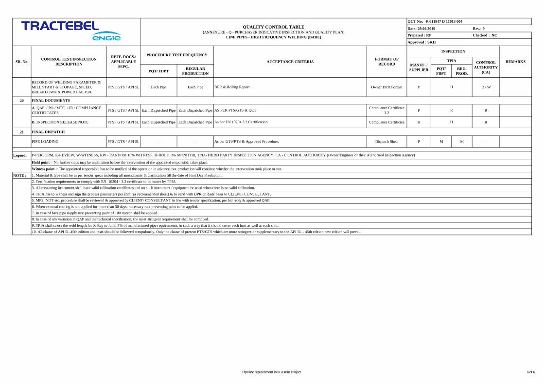
Date: 29.04.2019 Rev.: 0
PQT/ FDPT REGULARPRODUCTION
PQT/FDPT
REG.PROD.
QUALITY CONTROL TABLE(ANNEXURE - Q - PURCHASER INDICATIVE INSPECTION AND QUALITY PLAN)
LINE PIPES - HIGH FREQUENCY WELDING (BARE)
QCT No: P.011947 D 11013 004
Checked : NC
Approved : SKH
Prepared : RP
INSPECTION
CONTROLAUTHORITY
(CA)
REMARKSTPIACONTROL TEST/INSPECTIONDESCRIPTION
REFF. DOCS./APPLICABLE
SEPC.SR. No. ACCEPTANCE CRITERIA FORMAT OF
RECORD MANUF. /SUPPLIER
PROCEDURE TEST FREQUENCY
RECORD OF WELDING PARAMETER &MILL START & STOPAGE, SPEED,BREAKDOWN & POWER FAILURE
PTS / GTS / API 5L Each Pipe Each Pipe Owner DPR Format P R / W
20
A. QAP / PO / MTC / IR / COMPLIANCECERTIFICATES PTS / GTS / API 5L Each Dispatched Pipe Each Dispatched Pipe Compliance Certificate
3.2 P R
B. INSPECTION RELEASE NOTE PTS / GTS / API 5L Each Dispatched Pipe Each Dispatched Pipe Compliance Certificate H R
21
PIPE LOADING PTS / GTS / API 5L ---- ---- Dispatch Sheet P M M -
Legend:
NOTE :
FINAL DISPATCH
As per GTS/PTS & Approved Procedure.
P-PERFORM, R-REVIEW, W-WITNESS, RW - RANDOM 10% WITNESS, H-HOLD, M- MONITOR, TPIA-THIRD PARTY INSPECTION AGENCY, CA - CONTROL AUTHORITY (Owner/Engineer or their Authorised Inspection Agency)
1. Material & type shall be as per tender specs including all amendments & clarification till the date of First Day Production.
DPR & Rolling Report
FINAL DOCUMENTS
AS PER PTS/GTS & QCT
As per EN 10204 3.2 Certification
Hold point = No further steps may be undertaken before the intervention of the appointed responsible takes place.
Witness point = The appointed responsible has to be notified of the operation in advance, but production will continue whether the intervention took place or not.
H
R
H
2. Certification requirements to comply with EN 10204 - 3.2 certificate to be issues by TPIA.3. All measuring instrument shall have valid calibration certificates and no such instrument / equipment be used when there is no valid calibration.4. TPIA has to witness and sign the process parameters per shift (as recommended sheet) & to send with DPR on daily basis to CLIENT/ CONSULTANT.5. MPS, NDT etc. procedure shall be reviewed & approved by CLIENT/ CONSULTANT in line with tender specification, pre bid reply & approved QAP.6. When external coating is not applied for more than 30 days, necessary rust preventing paint to be applied.7. In case of bare pipe supply rust preventing paint of 100 micron shall be applied .8. In case of any variation in QAP and the technical specification, the most stringent requirement shall be complied.
10. All clause of API 5L 45th edition and tests should be followed scrupulously. Only the clause of present PTS/GTS which are more stringent or supplementary to the API 5L - 45th edition new edition will prevail.9. TPIA shall select the weld length for X-Ray to fulfill 5% of manufactured pipe requirements, in such a way that it should cover each heat as well as each shift.
Pipeline replacement in KG Basin Project 6 of 6
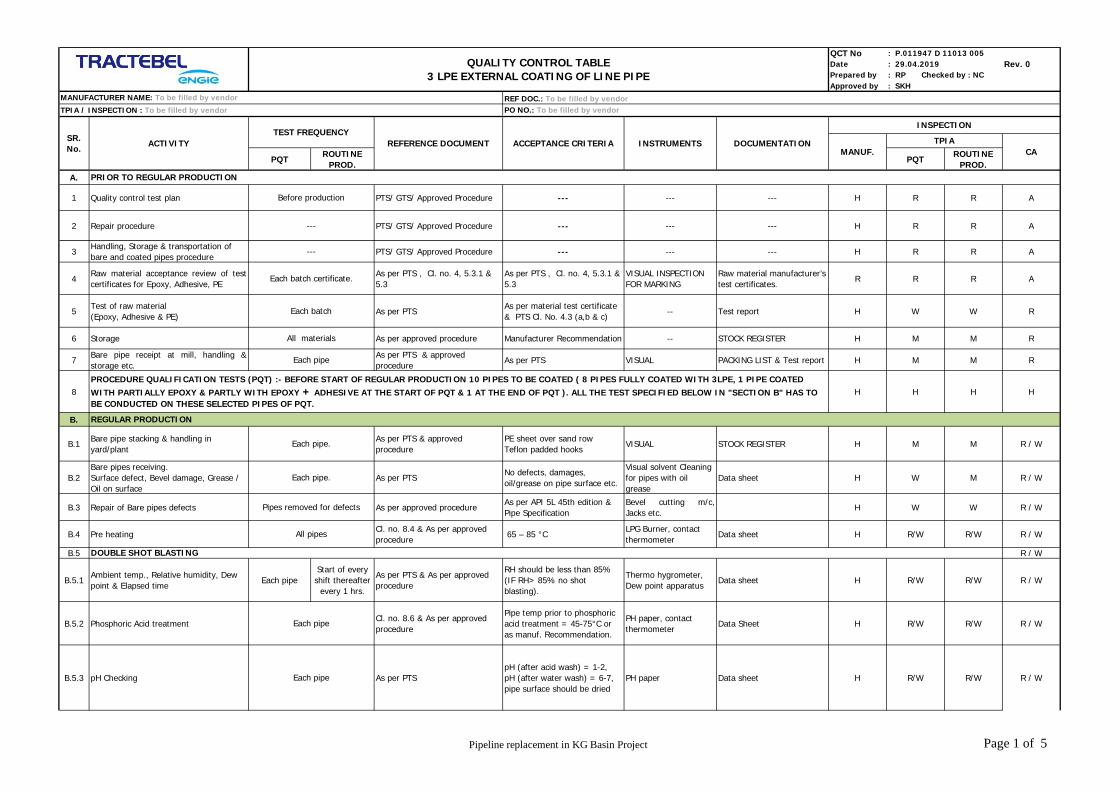
QCT No : P.011947 D 11013 005Date : 29.04.2019 Rev. 0Prepared by : RP Checked by : NCApproved by : SKH
PQTROUTINE
PROD.PQT
ROUTINEPROD.
A.
1 Quality control test plan PTS/ GTS/ Approved Procedure --- --- --- H R R A
2 Repair procedure PTS/ GTS/ Approved Procedure --- --- --- H R R A
3Handling, Storage & transportation ofbare and coated pipes procedure
PTS/ GTS/ Approved Procedure --- --- --- H R R A
4Raw material acceptance review of testcertificates for Epoxy, Adhesive, PE
As per PTS , Cl. no. 4, 5.3.1 &5.3
As per PTS , Cl. no. 4, 5.3.1 &5.3
VISUAL INSPECTIONFOR MARKING
Raw material manufacturer’stest certificates.
R R R A
5Test of raw material(Epoxy, Adhesive & PE)
As per PTSAs per material test certificate& PTS Cl. No. 4.3 (a,b & c)
-- Test report H W W R
6 Storage As per approved procedure Manufacturer Recommendation -- STOCK REGISTER H M M R
7Bare pipe receipt at mill, handling &storage etc.
As per PTS & approvedprocedure
As per PTS VISUAL PACKING LIST & Test report H M M R
8 H H H H
B.
B.1Bare pipe stacking & handling inyard/plant
As per PTS & approvedprocedure
PE sheet over sand rowTeflon padded hooks
VISUAL STOCK REGISTER H M M R / W
B.2Bare pipes receiving.Surface defect, Bevel damage, Grease /Oil on surface
As per PTSNo defects, damages,oil/grease on pipe surface etc.
Visual solvent Cleaningfor pipes with oilgrease
Data sheet H W M R / W
B.3 Repair of Bare pipes defects As per approved procedureAs per API 5L 45th edition &Pipe Specification
Bevel cutting m/c,Jacks etc.
H W W R / W
B.4 Pre heatingCl. no. 8.4 & As per approvedprocedure
65 – 85 °CLPG Burner, contactthermometer
Data sheet H R/W R/W R / W
B.5 R / W
B.5.1Ambient temp., Relative humidity, Dewpoint & Elapsed time
Each pipeStart of everyshift thereafter
every 1 hrs.
As per PTS & As per approvedprocedure
RH should be less than 85%(IF RH> 85% no shotblasting).
Thermo hygrometer,Dew point apparatus
Data sheet H R/W R/W R / W
B.5.2 Phosphoric Acid treatmentCl. no. 8.6 & As per approvedprocedure
Pipe temp prior to phosphoricacid treatment = 45-75°C oras manuf. Recommendation.
PH paper, contactthermometer
Data Sheet H R/W R/W R / W
B.5.3 pH Checking As per PTSpH (after acid wash) = 1-2,pH (after water wash) = 6-7,pipe surface should be dried
PH paper Data sheet H R/W R/W R / W
PRIOR TO REGULAR PRODUCTION
Before production
Each pipe
TPIA / INSPECTION : To be filled by vendor
INSTRUMENTSSR.No.
DOUBLE SHOT BLASTING
ACTIVITY ACCEPTANCE CRITERIA DOCUMENTATIONTEST FREQUENCY
MANUF.
PROCEDURE QUALIFICATION TESTS (PQT) :- BEFORE START OF REGULAR PRODUCTION 10 PIPES TO BE COATED ( 8 PIPES FULLY COATED WITH 3LPE, 1 PIPE COATEDWITH PARTIALLY EPOXY & PARTLY WITH EPOXY + ADHESIVE AT THE START OF PQT & 1 AT THE END OF PQT ). ALL THE TEST SPECIFIED BELOW IN "SECTION B" HAS TOBE CONDUCTED ON THESE SELECTED PIPES OF PQT.
---
---
Each batch certificate.
Each batch
All materials
Each pipe
Each pipe.
Each pipe.
Pipes removed for defects
REGULAR PRODUCTION
All pipes
Each pipe
CA
INSPECTION
REFERENCE DOCUMENT
REF DOC.: To be filled by vendorPO NO.: To be filled by vendor
QUALITY CONTROL TABLE3 LPE EXTERNAL COATING OF LINE PIPE
TPIA
MANUFACTURER NAME: To be filled by vendor
Pipeline replacement in KG Basin Project Page 1 of 5
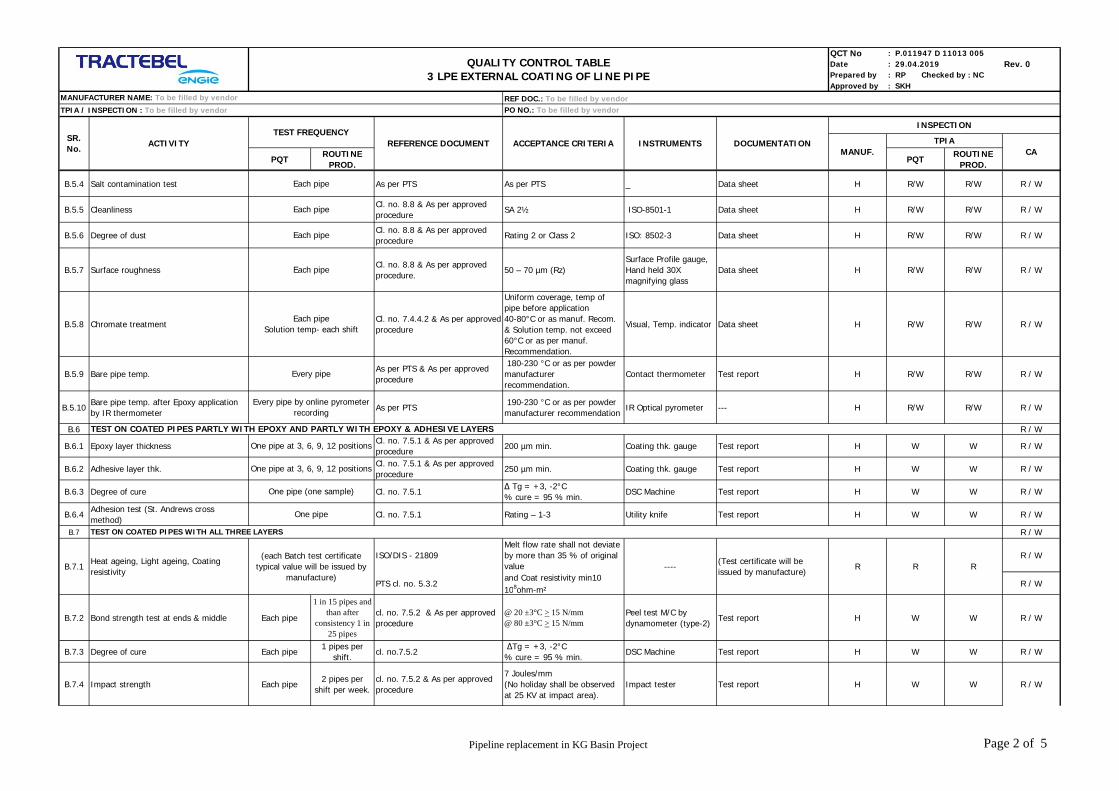
QCT No : P.011947 D 11013 005Date : 29.04.2019 Rev. 0Prepared by : RP Checked by : NCApproved by : SKH
PQTROUTINE
PROD.PQT
ROUTINEPROD.
TPIA / INSPECTION : To be filled by vendor
INSTRUMENTSSR.No.
ACTIVITY ACCEPTANCE CRITERIA DOCUMENTATIONTEST FREQUENCY
MANUF. CA
INSPECTION
REFERENCE DOCUMENT
REF DOC.: To be filled by vendorPO NO.: To be filled by vendor
QUALITY CONTROL TABLE3 LPE EXTERNAL COATING OF LINE PIPE
TPIA
MANUFACTURER NAME: To be filled by vendor
B.5.4 Salt contamination test As per PTS As per PTS _ Data sheet H R/W R/W R / W
B.5.5 CleanlinessCl. no. 8.8 & As per approvedprocedure
SA 2½ ISO-8501-1 Data sheet H R/W R/W R / W
B.5.6 Degree of dustCl. no. 8.8 & As per approvedprocedure
Rating 2 or Class 2 ISO: 8502-3 Data sheet H R/W R/W R / W
B.5.7 Surface roughnessCl. no. 8.8 & As per approvedprocedure.
50 – 70 µm (Rz)Surface Profile gauge,Hand held 30Xmagnifying glass
Data sheet H R/W R/W R / W
B.5.8 Chromate treatmentCl. no. 7.4.4.2 & As per approvedprocedure
Uniform coverage, temp ofpipe before application40-80°C or as manuf. Recom.& Solution temp. not exceed60°C or as per manuf.Recommendation.
Visual, Temp. indicator Data sheet H R/W R/W R / W
B.5.9 Bare pipe temp.As per PTS & As per approvedprocedure
180-230 °C or as per powdermanufacturerrecommendation.
Contact thermometer Test report H R/W R/W R / W
B.5.10Bare pipe temp. after Epoxy applicationby IR thermometer
As per PTS 190-230 °C or as per powdermanufacturer recommendation
IR Optical pyrometer --- H R/W R/W R / W
B.6 R / W
B.6.1 Epoxy layer thicknessCl. no. 7.5.1 & As per approvedprocedure
200 µm min. Coating thk. gauge Test report H W W R / W
B.6.2 Adhesive layer thk.Cl. no. 7.5.1 & As per approvedprocedure
250 µm min. Coating thk. gauge Test report H W W R / W
B.6.3 Degree of cure Cl. no. 7.5.1Δ Tg = +3, -2°C% cure = 95 % min.
DSC Machine Test report H W W R / W
B.6.4Adhesion test (St. Andrews crossmethod)
Cl. no. 7.5.1 Rating – 1-3 Utility knife Test report H W W R / W
B.7 R / W
ISO/DIS - 21809Melt flow rate shall not deviateby more than 35 % of originalvalue
R / W
PTS cl. no. 5.3.2and Coat resistivity min10108ohm-m²
R / W
B.7.2 Bond strength test at ends & middle Each pipe
1 in 15 pipes andthan after
consistency 1 in25 pipes
cl. no. 7.5.2 & As per approvedprocedure
@ 20 ±3°C > 15 N/mm@ 80 ±3°C > 15 N/mm
Peel test M/C bydynamometer (type-2)
Test report H W W R / W
B.7.3 Degree of cure Each pipe1 pipes per
shift.cl. no.7.5.2
∆Tg = +3, -2°C% cure = 95 % min.
DSC Machine Test report H W W R / W
B.7.4 Impact strength Each pipe2 pipes per
shift per week.cl. no. 7.5.2 & As per approvedprocedure
7 Joules/mm(No holiday shall be observedat 25 KV at impact area).
Impact tester Test report H W W R / W
----
One pipe at 3, 6, 9, 12 positions
One pipe
One pipe (one sample)
(each Batch test certificatetypical value will be issued by
manufacture)
Each pipe
Each pipe
Each pipe
Each pipe
Each pipeSolution temp- each shift
Every pipe
Every pipe by online pyrometerrecording
One pipe at 3, 6, 9, 12 positions
TEST ON COATED PIPES PARTLY WITH EPOXY AND PARTLY WITH EPOXY & ADHESIVE LAYERS
RR(Test certificate will beissued by manufacture)
R
TEST ON COATED PIPES WITH ALL THREE LAYERS
B.7.1Heat ageing, Light ageing, Coatingresistivity
Pipeline replacement in KG Basin Project Page 2 of 5
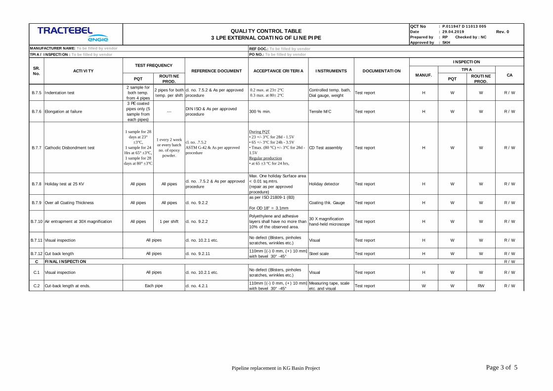
QCT No : P.011947 D 11013 005Date : 29.04.2019 Rev. 0Prepared by : RP Checked by : NCApproved by : SKH
PQTROUTINE
PROD.PQT
ROUTINEPROD.
TPIA / INSPECTION : To be filled by vendor
INSTRUMENTSSR.No.
ACTIVITY ACCEPTANCE CRITERIA DOCUMENTATIONTEST FREQUENCY
MANUF. CA
INSPECTION
REFERENCE DOCUMENT
REF DOC.: To be filled by vendorPO NO.: To be filled by vendor
QUALITY CONTROL TABLE3 LPE EXTERNAL COATING OF LINE PIPE
TPIA
MANUFACTURER NAME: To be filled by vendor
B.7.5 Indentation test2 sample forboth temp.
from 4 pipes
2 pipes for bothtemp. per shift
cl. no. 7.5.2 & As per approvedprocedure
0.2 max. at 23± 2°C 0.3 max. at 80± 2°C
Controlled temp. bath,Dial gauge, weight
Test report H W W R / W
B.7.6 Elongation at failure
3 PE coatedpipes only (5sample fromeach pipes)
---DIN ISO & As per approvedprocedure
300 % min. Tensile M/C Test report H W W R / W
B.7.7 Cathodic Disbondment test
1 sample for 28days at 23°
±3°C,1 sample for 24Hrs at 65° ±3°C,1 sample for 28
days at 80° ±3°C
1 every 2 weekor every batchno. of epoxy
powder.
cl. no. .7.5.2ASTM G-42 & As per approvedprocedure
During PQT• 23 +/- 3°C for 28d - 1.5V• 65 +/- 3°C for 24h - 3.5V• Tmax. (80 °C) +/- 3°C for 28d -1.5VRegular production• at 65 ±3 °C for 24 hrs,
CD Test assembly Test report H W W R / W
B.7.8 Holiday test at 25 KV All pipes All pipescl. no. .7.5.2 & As per approvedprocedure
Max. One holiday Surface area< 0.01 sq.mtrs.(repair as per approvedprocedure)
Holiday detector Test report H W W R / W
B.7.9 Over all Coating Thickness All pipes All pipes cl. no. 9.2.2as per ISO 21809-1 (B3)
For OD 18" = 3.1mmCoating thk. Gauge Test report H W W R / W
B.7.10 Air entrapment at 30X magnification All pipes 1 per shift cl. no. 9.2.2Polyethylene and adhesivelayers shall have no more than10% of the observed area.
30 X magnificationhand-held microscope
Test report H W W R / W
B.7.11 Visual inspection cl. no. 10.2.1 etc.No defect (Blisters, pinholesscratches, wrinkles etc.)
Visual Test report H W W R / W
B.7.12 Cut back length cl. no. 9.2.11110mm [(-) 0 mm, (+) 10 mm]with bevel 30° -45°
Steel scale Test report H W W R / W
C R / W
C.1 Visual inspection cl. no. 10.2.1 etc.No defect (Blisters, pinholesscratches, wrinkles etc.)
Visual Test report H W W R / W
C.2 Cut-back length at ends. cl. no. 4.2.1110mm [(-) 0 mm, (+) 10 mm]with bevel 30° -45°
Measuring tape, scaleetc. and visual
Test report W W RW R / W
FINAL INSPECTION
Each pipe
All pipes
All pipes
All pipes
Pipeline replacement in KG Basin Project Page 3 of 5

QCT No : P.011947 D 11013 005Date : 29.04.2019 Rev. 0Prepared by : RP Checked by : NCApproved by : SKH
PQTROUTINE
PROD.PQT
ROUTINEPROD.
TPIA / INSPECTION : To be filled by vendor
INSTRUMENTSSR.No.
ACTIVITY ACCEPTANCE CRITERIA DOCUMENTATIONTEST FREQUENCY
MANUF. CA
INSPECTION
REFERENCE DOCUMENT
REF DOC.: To be filled by vendorPO NO.: To be filled by vendor
QUALITY CONTROL TABLE3 LPE EXTERNAL COATING OF LINE PIPE
TPIA
MANUFACTURER NAME: To be filled by vendor
C.3Marking on coated pipesExternal color band
Each pipe Spray gun, Stencil paper etc.
Proper information on coatedsurface (ME side) i.e. asfollows. (1 mtr. From end
PROJECT........ PIPE DIA ..WALL THK…PIPE NO. .. LENGTH…. HEATNo. -----COATING No…, COLOURBAND, ANY OTHERINFORMATION CONSIDEREDRELEVANT BY COMPANY
As per PTS H M M R / W
H.
I
1 Handling Each pipe As per PTS
No damages on coated pipes.Support bed, min. 2 nos.support on trailor & securingby three wire rope coveredwith nylon rubber tubing
Crane with teflonpadded hooks, trailorwith rubber paddedbeds etc.
STOCK REGISTER H R/W R/W
2 Storage Each pipe As per PTS
Proper stacking on sand rowscovered with PE sheets withstack identification & layerseparator.
--do-- STOCK REGISTER H R/W R/W
J.
1 Digital thermometer Calibration procedureRef. Thermometers,water/ oil bath etc.
Test report H R/W R/W R / W
2 Thickness gauge. Calibration procedureRef. Thickness foils,steel subtract etc.
Test report H R/W R/W R / W
3 Roughness gauge Calibration procedureStandard Roughnessspecimen etc.
Test report H R/W R/W R / W
4 Holiday detector Calibration procedure By spark gap method Test report5 Hygrometer Calibration procedure By master hygrometer Test report
6 D Meter Calibration procedure By standard thickness block Test report H W W R / W
R / W
R / W
R / W
R / WSpark gap assembly /Calibrated meter
W
W W
W
WEvery 4 hours
Once in four month
Every time before use
Add or subtract the observedvalue w.r.t. reference
measurement.
Every month.
Every shift
Every shift
1
As per manufacturer’srecommendation
LEGEND : W = WITNESS; H= HOLD; M = MONITORING; R = REVIEW OF DOCUMENTS; R/W = RANDOM WITNESS ; A = APPROVED; TPIA = THIRD PARTY INSPECTION AGENCY; CA - CONTROL AUTHORITY
H
Raw Material Combination to be used During Production as per ANNEXURE – 1 of PTS )
COATING REPAIR
HANDLING & STORAGE
W
cl. no. 10.0
Cust spec.
CALIBRATION OF EQUIPMENT
2 Peel test on repair area One in 25 pipes Test report
Repair of Coating followed by holidaydetection at 25 KV
HAll coating
repair All repairs as per approvedprocedure
H
Test reportHeating torch, chisel,scale etc.
Spring balance
Pipeline replacement in KG Basin Project Page 4 of 5

QCT No : P.011947 D 11013 005Date : 29.04.2019 Rev. 0Prepared by : RP Checked by : NCApproved by : SKH
PQTROUTINE
PROD.PQT
ROUTINEPROD.
TPIA / INSPECTION : To be filled by vendor
INSTRUMENTSSR.No.
ACTIVITY ACCEPTANCE CRITERIA DOCUMENTATIONTEST FREQUENCY
MANUF. CA
INSPECTION
REFERENCE DOCUMENT
REF DOC.: To be filled by vendorPO NO.: To be filled by vendor
QUALITY CONTROL TABLE3 LPE EXTERNAL COATING OF LINE PIPE
TPIA
MANUFACTURER NAME: To be filled by vendor
Hold point = No further steps may be undertaken before the intervention of the appointed responsible takes place.
Witness point = The appointed responsible has to be notified of the operation in advance, but production will continue whether the intervention took place or not.
Notes: -12345678910
Owner / Owner's representative including TPIA will have the right to inspect any activity of manufacturing at any time.All reference Codes/ Standards, Documents, P.O. Copies shall be arranged by vendor / supplier for reference of TPIA/OWNER at the time of Inspection
At the time of deleivery of material in stores, vendor will submit copy of all related document of inspection along with release note & MTC.Certification requirement shall comply with European standard EN 10204:3.2 (latest edition)
TPIA along with Owner/Owner representative shall review all the documents related to QCT/Quality manuals/Drawings etc.submitted by supplier.
Special manufacturing procedures have to be approved or only previously approved procedures have to be used, in case of conflict between specifications more stringent condition shall be applicable.
The Above Testing and acceptance criteria are minimum requirements, however, manufacturer shall ensure that the product shall also comply to the additional requirements as per Particular Technical specifications(PTS)The supplier shall submit their own detailed QAP/ITP for First Day production & Regular production seperately which are prepared on the basis of above for approval of Owner/Owner's representative and TPIA.Owner/Owner representative shall review/approve all the documents related to QCT/Quality manuals/Drawings etc.submitted by supplier.Contractor shall in coordination with Supplier/Sub vendor issue detailed Production and Inspection schedule indicating the dates and the locations to facilitate Owner/Owner's representative and TPIA to organise Inspection.
Pipeline replacement in KG Basin Project Page 5 of 5

1
1.1 Name of Product P R R
1.2 Name of Manufacture P R R
1.3 Batch Number P R R
1.4 Date of Manufacturing P R R
1.5 Shelf Life P R R
1.6 Safety Data P R R
1.7 Coating Material Properties As per Manufacturer Spec. P R R
2 P H H
2.1 Verification of Pipe No., ASI No.As per Client's Specification andISO 15741
Each Pipe Each Pipe As per pipe Mill Tally sheet / External Coating Tally Sheet. Inspection Report P W R
2.2Visual Inspection of SurfaceCondition Prior to SurfacePreparation
As per Client's Specification andISO 15741
Each Pipe Each PipeVisual Examination, the surface shal l be free from any foreign matters suchas weld flux, spatters, oil & grease, etc.
Inspection Report P W RW
2.3Pipe Temperature before abrasiveblast cleaning
As per Client's Specification andISO 15741
Each Pipe Each Pipepipe temperature shall be 3 deg C above the dew point or min. curing temp.given by paint manufacturer.
Inspection Report P W R
2.4 Surface CleanlinessAs per Client's Specification andISO 15741
Each Pipe Each Pipe SA2 1/2 Inspection Report P W R
2.5 Salt ContaminationAs per Client's Specification andISO 15741
Each Pipe Each Pipe 2µg/cm2 Max Inspection Report P W RW
2.6 Roughness ProfileAs per Client's Specification andISO 15741
Each Pipe Each Pipe 30-60um Inspection Report P W R
2.7 Ambient ConditionsAs per Client's Specification andISO 15741
Each Pipe Each Pipe Relative Humidity, Ambient temp., Dew point Inspection Report P W R
2.8 Paint Preparation before mixingAs per Paint Manufacturersrecommendation
Every time paintis mixed andevery timepainting isinterrupted
Every Time paintis mixed andevery timepainting is
interrupted.
Before removing from containers, stir or agitate the components of paintuntill it is homegenous. Care shall be taken to avoid excessive entraning of airinto the components.
P W R
2.9 Mixed Paint ViscosityAs per Paint Manufacturersrecommendation
Every Hour Every Shift As per paint manufacturer Recommendation. Inspection Report P W R
2.10 Wet film ThicknessAs per Paint Manufacturersrecommendation
Each Pipe Every 20 pipes As per paint manufacturer Recommendation. Inspection Report P W RW
2.11 Coating cut back Each Pipe Each Pipe 50 mm (+/- 5 mm) Inspection Report P W RW
2.12 Visual inspection of coated pipes Each Pipe Each PipeCoating should be uniform in thickness and free of iregularities. Light runs orsags shall be accepted if it is not required to be repaired.
Inspection Report P W RW
QUALITY CONTROL TABLEINTERNAL EPOXY COATING OF LINE PIPE
REF DOC.: To be filled by vendor
Every Change ofBatch of Material
Visual Examination
QCT No.: P.011947 D 11013 006
Prepared : RP Checked : NCApproved : SKH
INSPECTION
VENDOR
Date: 29.04.2019
SRNO.
ACTIVITYACCEPTABLE
STANDARD ORCLIENT'S SPEC
MANUFACTURER NAME: To be filled by vendorTPIA / INSPECTION : To be filled by vendor
TEST FREQUENCY
Rev.: A
Manufacturer TestCertificates
CATPIA
PROCEDURE QUALIFICATION TEST -(TEST ON 3 SELECTED PIPES OUT OF 25 PIPES PRODUCED TO ESTABLISHED PROCESS AND PARAMETERS FOR PROCESS OF COATING
Manufacturer Product DataSheets and Health & Safety Data
Sheet
At Start of EveryShift
Every Batch
PQTPRODUCTIO
N
PO NO.: To be filled by vendor
DOCUMENTTYPE
ACCEPDANCE CRITERIA
RAW MATERIAL PROPERTIES
Pipeline replacement in KG Basin Project Page 1 of 3

QUALITY CONTROL TABLEINTERNAL EPOXY COATING OF LINE PIPE
REF DOC.: To be filled by vendor
QCT No.: P.011947 D 11013 006
Prepared : RP Checked : NCApproved : SKH
INSPECTION
VENDOR
Date: 29.04.2019
SRNO.
ACTIVITYACCEPTABLE
STANDARD ORCLIENT'S SPEC
MANUFACTURER NAME: To be filled by vendorTPIA / INSPECTION : To be filled by vendor
TEST FREQUENCY
Rev.: A
CATPIAPQTPRODUCTIO
N
PO NO.: To be filled by vendor
DOCUMENTTYPE
ACCEPDANCE CRITERIA
2.13 Dry Film ThicknessAs per Client's Specification andISO 15741
Each Pipe Each Pipe The minimum Dry film thickness shall be 100 (+ 20, - 0 um). Inspection Report P W W
2.14 RoughnessAs per Client's Specification andISO 15741
Each Pipe Each Pipe Coating roughness shall be 10 um. Inspection Report P W W
2.15 Pinhole Test (On Glass panel)As per Client's Specification andISO 15741
02 pipes Twice / Shift No pinhole Inspection Report P W W
2.16 Bend TestAs per Client's Specification andISO 15741
02 pipes Twice / Shift No loss of adhesion Inspection Report P W W
2.17 Buchholz Hardness TestAs per Client's Specification andISO 15741
02 pipes Twice / Shift Min. 94 Buchholz Inspection Report P W W
2.18 Curing Test AdhensionAs per Client's Specification andISO 15741
02 pipes Twice / Shift Coating shall not show any Blister, wrinkle or softening. Inspection Report P W W
2.19 Adhesion TestAs per Client's Specification andISO 15741
02 pipes Twice / Shift No lifting other than cutting. Inspection Report P W W
3
3.1 Coating RepairAs per Paint Manufacturers
recommendationAs Per manufacturer recommendation. -- P W RW
4
4.1 Final clearence of Coated Pipes -Final inspection and dimensiona report shall be prepared for all acceptedpipes.
Inspection Report P RW RW
4.2 Visual Inspection of Coated Pipes -Coating should be uniform in thickness and should be free ofiregularities.Light runs or sags shall be accepted if it is not requried to be repaired.
- P RW RW
4.3 Marking on accepted pipes As per pipe Mill Data & Approved Marking procedure. - P RW RW
5
5.1 Dry film thickness Gauge Oncer per shit Oncer per shitAdd or subtract the observed value with reference to reference measurement.In addition calibration TC shall be Review.
Inspection Report P RW RW
5.2 Roughness Gauge Oncer per shit Oncer per shit Inspection Report P RW RW
5.3 Temperature Gauge Oncer per shit Oncer per shit Inspection Report P RW RW
6
6.1Handling Transportation andstorage of externally coatedinternally coated
As per Client's Specification andISO 15741
No Damages to coated pipes - P RW RW
6.2 Coating raw materialAs per Manufacturers
RecommendationsSorage of raw material shall be as per Raw material manufacturerrecommendation.
Manufacturerproduct data sheet
P - -
HANDLING TRANSPORTATION & STORAGE
As per specified procedure
All Accepted pipes
The defective coatings or areaswith insufficient dry film thickness.And other Damage including Panel
ReparFINAL INSPECTION
CALIBRATION OF MEASURING AND MONITORING INSTRUMENTS
Each Pipe
All Accepted pipes
REPAIR
INSPECTION AND TESTING ON PANELS (GLASS + STEEL)
-
Pipeline replacement in KG Basin Project Page 2 of 3

QUALITY CONTROL TABLEINTERNAL EPOXY COATING OF LINE PIPE
REF DOC.: To be filled by vendor
QCT No.: P.011947 D 11013 006
Prepared : RP Checked : NCApproved : SKH
INSPECTION
VENDOR
Date: 29.04.2019
SRNO.
ACTIVITYACCEPTABLE
STANDARD ORCLIENT'S SPEC
MANUFACTURER NAME: To be filled by vendorTPIA / INSPECTION : To be filled by vendor
TEST FREQUENCY
Rev.: A
CATPIAPQTPRODUCTIO
N
PO NO.: To be filled by vendor
DOCUMENTTYPE
ACCEPDANCE CRITERIA
7
7.1Release note / acceptancecertificate of accepted coatedpipes
-All Accepted
pipesAll Accepted
pipesReview of final inspection report, test frequency inspection of test certificate,IRN etc.
P RW H
LEGEND
Hold point = No further steps may be undertaken before the intervention of the appointed responsible takes place.
Witness point = The appointed responsible has to be notified of the operation in advance, but production will continue whether the intervention took place or not.Note :
8. In case of variation in the specification and QCT, enclosed in the Bid package, the stringent requirements shall be complied with.
FINAL REPORT / DOCUMENTATION
P - Perform, R - Review, W - Witness, H- Hold RW - Random 10% witness TPIOA - Third Party Inspection Agency, CA - CONTROL AUTHORITY (OWNER / OWNER'S REPRESENTATIVE).
1. Material & Type Shall be as per tender specs / data sheet.2. TPIA shall issue 3.2 certificates as per EN 10204.3. All measuring instrument shall have valid calibraton certificates.4. TPIA has to witness and sign the process parameters per shift (as recommended sheet) & to send with DPR ondaily basis to client / PMC.5. The combination of Raw material shall be maintained same for the total order and no change is permitted, the manufacturer shall arrange the required material in advance.6. Sample from any one lot shall be tested by client under their witness third party lab at discretion.7. The QAP shall be prepared by the manufacturer as per actual requirements specified in the bid document and submitted for owner / consultant's approval.
Pipeline replacement in KG Basin Project Page 3 of 3
RECOMMENDED
VENDOR LIST P.011947 D 11040 001
Rev. 0 - 29.04.2019 Supply of Coated Line Pipe for Pipeline replacement in KG Basin Project Page 1 of 18
VENDOR LOGO
IRCA LOGO
PIPELINE REPLACEMENT IN KG BASIN PROJECT
TRACTEBEL ENGINEERING PVT. LTD.
RECOMMENDED VENDOR LIST
REPORT
DOC. NO. P.011947-D-11040-001
0 29.04.2019 Issued as Standard Specification RP SKG SKH
Rev. Date Description Prepared by Checked by Approved by
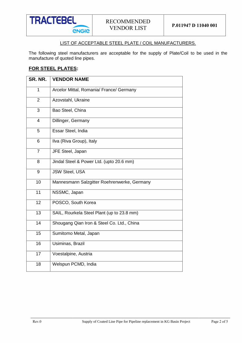
RECOMMENDED
VENDOR LIST P.011947 D 11040 001
Rev.0 Supply of Coated Line Pipe for Pipeline replacement in KG Basin Project Page 2 of 5
LIST OF ACCEPTABLE STEEL PLATE / COIL MANUFACTURERS.
The following steel manufacturers are acceptable for the supply of Plate/Coil to be used in the manufacture of quoted line pipes.
FOR STEEL PLATES:
SR. NR. VENDOR NAME
1 Arcelor Mittal, Romania/ France/ Germany
2 Azovstahl, Ukraine
3 Bao Steel, China
4 Dillinger, Germany
5 Essar Steel, India
6 Ilva (Riva Group), Italy
7 JFE Steel, Japan
8 Jindal Steel & Power Ltd. (upto 20.6 mm)
9 JSW Steel, USA
10 Mannesmann Salzgitter Roehrenwerke, Germany
11 NSSMC, Japan
12 POSCO, South Korea
13 SAIL, Rourkela Steel Plant (up to 23.8 mm)
14 Shougang Qian Iron & Steel Co. Ltd., China
15 Sumitomo Metal, Japan
16 Usiminas, Brazil
17 Voestalpine, Austria
18 Welspun PCMD, India
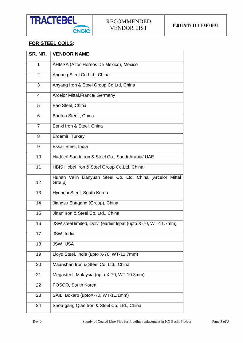
RECOMMENDED
VENDOR LIST P.011947 D 11040 001
Rev.0 Supply of Coated Line Pipe for Pipeline replacement in KG Basin Project Page 3 of 5
FOR STEEL COILS:
SR. NR. VENDOR NAME
1 AHMSA (Altos Hornos De Mexico), Mexico
2 Angang Steel Co.Ltd., China
3 Anyang Iron & Steel Group Co.Ltd. China
4 Arcelor Mittal,France/ Germany
5 Bao Steel, China
6 Baotou Steel , China
7 Benxi Iron & Steel, China
8 Erdemir, Turkey
9 Essar Steel, India
10 Hadeed Saudi Iron & Steel Co., Saudi Arabia/ UAE
11 HBIS Hebei Iron & Steel Group Co.Ltd, China
12 Hunan Valin Lianyuan Steel Co. Ltd. China (Arcelor Mittal Group)
13 Hyundai Steel, South Korea
14 Jiangsu Shagang (Group), China
15 Jinan Iron & Steel Co. Ltd., China
16 JSW steel limited, Dolvi (earlier lspat (upto X-70, WT-11.7mm)
17 JSW, India
18 JSW, USA
19 Lloyd Steel, India (upto X-70, WT-11.7mm)
20 Maanshan Iron & Steel Co. Ltd., China
21 Megasteel, Malaysia (upto X-70, WT-10.3mm)
22 POSCO, South Korea
23 SAIL, Bokaro (uptoX-70, WT-11.1mm)
24 Shou-gang Qian Iron & Steel Co. Ltd., China
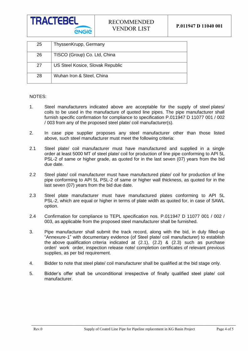
RECOMMENDED
VENDOR LIST P.011947 D 11040 001
Rev.0 Supply of Coated Line Pipe for Pipeline replacement in KG Basin Project Page 4 of 5
25 ThyssenKrupp, Germany
26 TISCO (Group) Co. Ltd, China
27 US Steel Kosice, Slovak Republic
28 Wuhan Iron & Steel, China
NOTES:
1. Steel manufacturers indicated above are acceptable for the supply of steel plates/ coils to be used in the manufacture of quoted line pipes. The pipe manufacturer shall furnish specific confirmation for compliance to specification P.011947 D 11077 001 / 002 / 003 from any of the proposed steel plate/ coil manufacturer(s).
2. In case pipe supplier proposes any steel manufacturer other than those listed above, such steel manufacturer must meet the following criteria:
2.1 Steel plate/ coil manufacturer must have manufactured and supplied in a single order at least 5000 MT of steel plate/ coil for production of line pipe conforming to API 5L PSL-2 of same or higher grade, as quoted for in the last seven (07) years from the bid due date.
2.2 Steel plate/ coil manufacturer must have manufactured plate/ coil for production of line pipe conforming to API 5L PSL-2 of same or higher wall thickness, as quoted for in the last seven (07) years from the bid due date.
2.3 Steel plate manufacturer must have manufactured plates conforming to API 5L PSL-2, which are equal or higher in terms of plate width as quoted for, in case of SAWL option.
2.4 Confirmation for compliance to TEPL specification nos. P.011947 D 11077 001 / 002 / 003, as applicable from the proposed steel manufacturer shall be furnished.
3. Pipe manufacturer shall submit the track record, along with the bid, in duly filled-up “Annexure-1” with documentary evidence (of Steel plate/ coil manufacturer) to establish the above qualification criteria indicated at (2.1), (2.2) & (2.3) such as purchase order/ work order, inspection release note/ completion certificates of relevant previous supplies, as per bid requirement.
4. Bidder to note that steel plate/ coil manufacturer shall be qualified at the bid stage only.
5. Bidder’s offer shall be unconditional irrespective of finally qualified steel plate/ coil manufacturer.

RECOMMENDED
VENDOR LIST P.011947 D 11040 001
Rev.0 Supply of Coated Line Pipe for Pipeline replacement in KG Basin Project Page 5 of 5
ANNEXURE-1
At the helm of the Energy Transition, Tractebel provides a full range of engineering and advisory servicesthroughout the life cycle of its clients’ projects, including design and project management. As one of the world’sleading engineering and advisory companies and with more than 150 years of experience, it's our mission toactively shape the world of tomorrow. With about 5,000 experts and presence in more than 70 countries, we areable to offer our customers multidisciplinary solutions in energy, water and urban.
TRACTEBEL ENGINEERING PVT. LTD.Intec House 37Institutional Area, Sector 44122 002 - Gurgaon - INDIAtractebel-engie.com
Syed Kaiumul HUSSAINtel. +91 124 669 7500fax +39 06 [email protected]