supplementary service manual - maritime propulsion
TRANSCRIPT
9 9 5 0 1 - 9 2 J 0 0 - 0 1 E
SUPPLEMENTARY SERVICE MANUAL

FOREWORD
This supplementary service manual describes service data and servicing procedures which differ from thoseof the DF90T/115T “K1” models.The entire manual should be thoroughly reviewed before any servicing is performed.
NOTE:• Refer to the DF90T/115T service manual (P/no. 99500-90J00-01E) for details which are not given in this
supplementary service manual.• Use this supplement with the following service manual:
DF90T/115T Service manual (P/no. 99500-90J00-01E)
CONTENTSGENERAL INFORMATION ________________________________________ 2
SPECIFICATIONS ___________________________________________ 2SERVICE DATA _____________________________________________ 4TIGHTENING TORQUE _______________________________________ 11SPECIAL TOOLS____________________________________________ 13MATERIALS REQUIRED _____________________________________ 16
ENGINE CONTROL ______________________________________________ 17POWER UNIT ___________________________________________________ 18
ENGINE OIL COOLER _______________________________________ 18• Removal/Installation _______________________________________ 19CAMSHAFT ________________________________________________ 20CYLINDER BLOCK__________________________________________ 21PISTON & PISTON RING _____________________________________ 21CRANKSHAFT _____________________________________________ 22CONROD ASSEMBLY _______________________________________ 22
MID UNIT ______________________________________________________ 23POWER TRIM AND TILT __________________________________________ 25
SERVICE PROCEDURE ______________________________________ 25OIL LEVEL / AIR BLEEDING _______________________________ 25
POWER TRIM AND TILT UNIT _________________________________ 26REMOVAL ______________________________________________ 26DISASSEMBLY __________________________________________ 27CLEANING AND INSPECTING _____________________________ 30REASSEMBLY___________________________________________ 31PTT MOTOR ____________________________________________ 33INSTALLATION __________________________________________ 37COMPONENT PARTS _____________________________________ 39OPERATION ____________________________________________ 39
LOWER UNIT (Normal rotation model) ______________________________ 46REMOVAL AND INSTALLATION_______________________________ 46DISASSEMBLY ____________________________________________ 46ASSEMBLY________________________________________________ 51LOWER UNIT GEARS-SHIMMING AND ADJUSTMENT____________ 61
COUNTER ROTATION LOWER UNIT (DF140Z) _______________________ 66REMOVAL AND INSTALLATION _______________________________ 67DISASSEMBLY _____________________________________________ 67INSPECTION _______________________________________________ 72ASSEMBLY ________________________________________________ 76LOWER UNIT GEARS-SHIMMING AND ADJUSTMENT(Counter rotation model) _____________________________________ 86
WIRING DIAGRAM ______________________________________________ 92HOSE ROUTING ________________________________________________ 93
2 DF140/140Z [GENERAL INFORMATION]
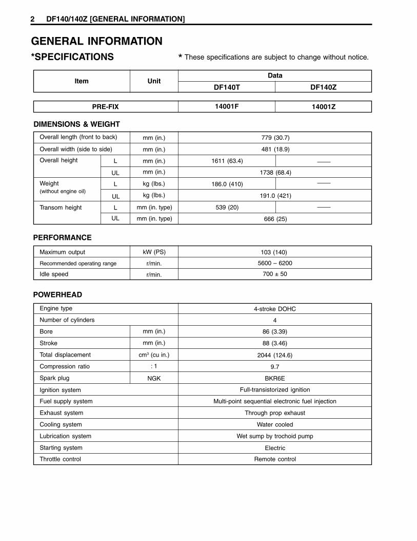
DIMENSIONS & WEIGHT
Overall length (front to back) mm (in.)
Overall width (side to side) mm (in.)
Overall height L mm (in.)
UL mm (in.)
Weight(without engine oil)
UL kg (Ibs.)
L
UL
kg (Ibs.)
PERFORMANCE
Maximum output kW (PS)
Recommended operating range r/min.
Idle speed r/min.
103 (140)
POWERHEAD
Engine type 4-stroke DOHC
Number of cylinders 4
mm (in.) 86 (3.39)
mm (in.) 88 (3.46)
cm3 (cu in.) 2044 (124.6)
: 1 9.7
NGK BKR6E
Full-transistorized ignition
Multi-point sequential electronic fuel injection
Through prop exhaust
Water cooled
Wet sump by trochoid pump
mm (in. type)Transom height
mm (in. type)
Remote control
Electric
Item UnitData
PRE-FIX 14001F
Bore
Stroke
Total displacement
Compression ratio
Spark plug
Ignition system
Fuel supply system
Exhaust system
Cooling system
Lubrication system
Starting system
Throttle control
779 (30.7)
481 (18.9)
1611 (63.4)
1738 (68.4)
186.0 (410)
191.0 (421)
539 (20)
666 (25)
DF140T DF140Z
14001Z
L
5600 – 6200
* These specifications are subject to change without notice.
700 ± 50
GENERAL INFORMATION*SPECIFICATIONS

DF140/140Z [GENERAL INFORMATION] 3
DF140T
Propeller shaft rotation (when shift into forward)
Viscosity rating SAE10W-40
Suzuki highly recommends that you use alcohol-free unleaded gasolinewith a minimum pump octane rating of 87 ( 2 method) or 91(Research method). However, blends of unleaded gasoline and alcohol withequivalent octane content may be used.
FUEL & OIL
Engine oil API classification SE, SF, SG, SH, SJ
Engine oil amountsL (US/Imp. qt)
5.5 (5.8/4.8) : Oil change only
5.7 (6.0/5.0) : Oil filter change
R + M
ml (US/Imp. oz)
Gear oil
Gearcase oil capacity
SUZUKI Outboard Motor Gear Oil (SAE #90 hypoid gear oil)
1050 (35.5/37.0)
BRACKET
Trim angle
Number of trim position
Maximum tilt angle degree
Reversing system Gear
Transmission Forward-Neutral-Reverse
Reduction system Bevel gear
Gear ratio
Drive line impact protection Spline drive rubber hub
Blade × Diam. (in.) × Pitch (in.)
3 × 13-1/2 × 15
3 × 14 × 17
3 × 14 × 19
3 × 14 × 21
3 × 14 × 23
3 × 14 × 18
3 × 14 × 20
3 × 14 × 22
3 × 14 × 24
Fuel
LOWER UNIT
PTT system
PTT system
75
Item UnitData
DF140Z
12 : 23 (1.92)
clockwise counterclockwise
: Aluminum propeller
: Stainless steel propeller
3 × 14 × 18
3 × 14 × 20
3 × 14 × 22
3 × 14 × 24
Propeller

4 DF140/140Z [GENERAL INFORMATION]
r/min.
r/min.
1200 – 1600 (12 – 16, 171 – 228)kPa (kg/cm2. psi)
100 (1.0, 14)kPa (kg/cm2. psi)
440 – 490 (4.5 – 5.0, 64 – 71) at 3000 r/min.
(at normal operating temp.)kPa (kg/cm2. psi)
L (US/Imp. qt)
58 – 62 (136 – 143)°C (°F)
API classification SE, SF, SG, SH, SJ
Viscosity rating SAE 10W-40
5.5 (5.8/4.8) : Oil change only
5.7 (6.0/5.0) : Oil filter change
*SERVICE DATA
POWERHEAD
** Figures shown are guidelines only, not absolute service limits.
Recommended operating range
Idle speed
**Cylinder compression
**Cylinder compression max.
difference between any three
cylinders
**Engine oil pressure
Engine oil
Engine oil amounts
Thermostat operating
temperature
700 ± 50 (in-gear : 700 ± 50)
5600 – 6200
Item UnitData
DF140T DF140Z
* These service data are subject to change without notice.
1st reduction gear ratio
(Crankshaft drive gear: Driven gear)29 : 36 (1.24)
2nd reduction gear ratio
(Lower unit gear)
Total reduction gear ratio
REDUCTION SYSTEM
12 : 23 (1.92)
2.38 36 × 2329 12
Item UnitData
DF140ZDF140T

DF140/140Z [GENERAL INFORMATION] 5
39.520 – 39.680 (1.5560 – 1.5622)
39.420 (1.5520)
39.220 (1.5441)
39.320 – 39.480 (1.5480 – 1.5543)
0.05 (0.002)mm (in.)Limit
mm (in.)
0.10 (0.004)mm (in.)Limit
STD
Limit mm (in.)IN
mm (in.)STD
Limit mm (in.)EX
0.020 – 0.062 (0.0008 – 0.0024)mm (in.)STD
Limit 0.120 (0.0047)mm (in.)
CYLINDER HEAD / CAMSHAFT
Cam height
Manifold seating facesdistortion
Camshaft journaloil clearance
Cylinder head distortion
Item UnitData
DF140Z
STD
Limit
Top,
2nd,
3rd,
4th
Camshaft journal(housing) inside diameter
5th
mm (in.)STD
Limit mm (in.)
STD
Limit5th
Top,
2nd,
3rd,
4th
Camshaftjournal outsidediameter
mm (in.)STD
Limit mm (in.)
STD
Limit5th
Top,
2nd,
3rd,
4th
mm (in.)
mm (in.)
0.10 (0.004)mm (in.)Limit
0.025 – 0.066 (0.0010 – 0.0026)mm (in.)STD
0.150 (0.0059)mm (in.)Limit
30.959 – 30.975 (1.2189 – 1.2195)mm (in.)STD
31.000 – 31.025 (1.2203 – 1.2215)mm (in.)STD
Camshaft runout
Cylinder head boreto tappet clearance
Tappet outerdiameter
Cylinder head bore
mm (in.)
0.045 – 0.087 (0.0018 – 0.0034)
0.120 (0.0047)
mm (in.)
mm (in.)
23.000 – 23.021 (0.9055 – 0.9063)
26.000 – 26.021 (1.0236 – 1.0244)
22.959 – 22.980 (0.9039 – 0.9047)
25.934 – 25.955 (1.0210 – 1.0219)
23.171 (0.9122)
26.171 (1.0304)
22.869 (0.9004)
25.844 (1.0175)
mm (in.)
DF140T

6 DF140/140Z [GENERAL INFORMATION]
33 (1.2992)mm (in.)IN
mm (in.)STD
STD mm (in.)
mm (in.)STD
Limit mm (in.)
0.045 – 0.072 (0.0018 – 0.0028)mm (in.)STD
Limit 0.090 (0.0035)mm (in.)
IN,EX mm (in.)STD 6.000 – 6.012 (0.2362 – 0.2367)
28 (1.1024)mm (in.)EX
IN
EX
0.020 – 0.047 (0.0008 – 0.0019)
0.070 (0.0028)IN
EX
IN
EX
15°, 45°, 60°
15°, 45°
IN,EX mm (in.)STD 13.5 (0.5315)
mm (in.)STD
STD mm (in.)
IN
EX
5.965 – 5.980 (0.2348 – 0.2354)
5.940 – 5.955 (0.2339 – 0.2344)
mm (in.)Limit
Limit mm (in.)
IN
EX
0.14 (0.0055)
0.18 (0.0071)
IN,EX mm (in.)Limit 0.05 (0.0020)
IN,EX mm (in.)Limit 0.08 (0.0031)
mm (in.)STD
LimitIN
1.0 (0.0394)
0.7 (0.0276)
mm (in.)STD
Limit mm (in.)EX
1.20 (0.0472)
0.7 (0.0276)
mm (in.)STD
STD mm (in.)
IN
EX
1.1 – 1.3 (0.0433 – 0.0512)
1.1 – 1.3 (0.0433 – 0.0512)
42.73 (1.6823)mm (in.)STD
41.02 (1.6150)mm (in.)Limit
164 – 190 (16.7 – 19.3, 36.7 – 42.5) for 32.6 mm (1.28 in.)N (kg, Ibs)STD
151 (15.1, 33.3) for 32.6 mm (1.28 in.)N (kg, Ibs)Limit
2.0 (0.079)mm (in.)Limit
VALVE / VALVE GUIDE
Tappet clearance(Cold enginecondition)
Valve diameter
Valve guide tovalve stemclearance
Valve guideinside diameter
Valve seat angle
Valve guideprotrusion
Valve stemoutside diameter
Valve stem enddeflection
Valve stem runout
Valve headradial runout
Valve headthickness
Valve seatcontact width
Valve spring freelength
Valve spring tension
Valve springsquareness
Item UnitData
DF140T DF140Z
mm (in.)
0.23 – 0.27 (0.009 – 0.011)
0.23 – 0.27 (0.009 – 0.011)
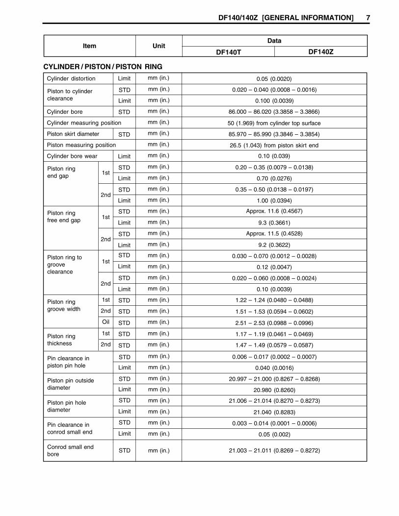
DF140/140Z [GENERAL INFORMATION] 7
0.05 (0.0020)mm (in.)Limit
mm (in.) 0.20 – 0.35 (0.0079 – 0.0138)STD
Limit mm (in.) 0.70 (0.0276)1st
mm (in.) 0.35 – 0.50 (0.0138 – 0.0197)STD
Limit mm (in.) 1.00 (0.0394)2nd
mm (in.) 0.020 – 0.040 (0.0008 – 0.0016)STD
Limit mm (in.) 0.100 (0.0039)
86.000 – 86.020 (3.3858 – 3.3866)mm (in.)STD
50 (1.969) from cylinder top surfacemm (in.)
85.970 – 85.990 (3.3846 – 3.3854)mm (in.)STD
26.5 (1.043) from piston skirt endmm (in.)
0.10 (0.039)mm (in.)Limit
mm (in.) Approx. 11.6 (0.4567)STD
Limit mm (in.) 9.3 (0.3661)1st
mm (in.) Approx. 11.5 (0.4528)STD
Limit mm (in.) 9.2 (0.3622)2nd
mm (in.) 1.22 – 1.24 (0.0480 – 0.0488)1st
mm (in.) 1.51 – 1.53 (0.0594 – 0.0602)
mm (in.) 2.51 – 2.53 (0.0988 – 0.0996)
2nd
Oil
mm (in.) 0.030 – 0.070 (0.0012 – 0.0028)STD
Limit mm (in.) 0.12 (0.0047)1st
mm (in.) 0.020 – 0.060 (0.0008 – 0.0024)STD
Limit mm (in.) 0.10 (0.0039)2nd
mm (in.) 1.17 – 1.19 (0.0461 – 0.0469)STD
STD mm (in.) 1.47 – 1.49 (0.0579 – 0.0587)
1st
2nd
mm (in.) 0.006 – 0.017 (0.0002 – 0.0007)STD
Limit mm (in.) 0.040 (0.0016)
mm (in.) 20.997 – 21.000 (0.8267 – 0.8268)STD
Limit mm (in.) 20.980 (0.8260)
mm (in.) 21.006 – 21.014 (0.8270 – 0.8273)STD
Limit mm (in.) 21.040 (0.8283)
mm (in.) 0.003 – 0.014 (0.0001 – 0.0006)STD
Limit mm (in.) 0.05 (0.002)
mm (in.) 21.003 – 21.011 (0.8269 – 0.8272)STD
STD
STD
STD
Piston ringend gap
Cylinder distortion
Piston to cylinderclearance
Cylinder bore
Cylinder measuring position
Piston skirt diameter
Piston measuring position
Cylinder bore wear
Piston ringfree end gap
Piston ringgroove width
Piston ring togrooveclearance
Piston ringthickness
Pin clearance inpiston pin hole
Piston pin outsidediameter
Piston pin holediameter
Pin clearance inconrod small end
Conrod small endbore
Item UnitData
DF140ZDF140T
CYLINDER / PISTON / PISTON RING
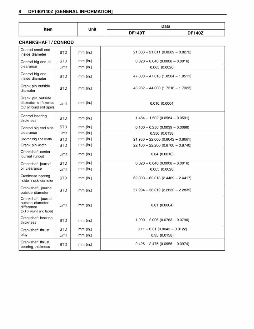
8 DF140/140Z [GENERAL INFORMATION]
Item UnitData
DF140T DF140Z
CRANKSHAFT / CONROD
Conrod small endinside diameter
Conrod big end oilclearance
Conrod big endinside diameter
Crank pin outsidediameter
Crank pin outsidediameter difference(out of round and taper)
Conrod bearingthickness
Conrod big end sideclearance
Conrod big end width
Crank pin width
Crankshaft centerjournal runout
Crankshaft journaloil clearance
Crankcase bearingholder inside diameter
Crankshaft journaloutside diameter
Crankshaft journaloutside diameterdifference(out of round and taper)
Crankshaft bearingthickness
Crankshaft thrustplay
Crankshaft thrustbearing thickness
21.003 – 21.011 (0.8269 – 0.8272)
0.020 – 0.040 (0.0008 – 0.0016)
0.065 (0.0026)
47.000 – 47.018 (1.8504 – 1.8511)
43.982 – 44.000 (1.7316 – 1.7323)
0.010 (0.0004)
1.484 – 1.502 (0.0584 – 0.0591)
0.100 – 0.250 (0.0039 – 0.0098)
0.350 (0.0138)
21.950 – 22.000 (0.8642 – 0.8661)
22.100 – 22.200 (0.8700 – 0.8740)
0.04 (0.0016)
0.020 – 0.040 (0.0008 – 0.0016)
0.065 (0.0026)
62.000 – 62.018 (2.4409 – 2.4417)
57.994 – 58.012 (2.2832 – 2.2839)
0.01 (0.0004)
1.990 – 2.006 (0.0783 – 0.0790)
0.11 – 0.31 (0.0043 – 0.0122)
0.35 (0.0138)
2.425 – 2.475 (0.0955 – 0.0974)
mm (in.)
mm (in.)
mm (in.)
mm (in.)
mm (in.)
mm (in.)
mm (in.)
mm (in.)
mm (in.)
mm (in.)
mm (in.)
mm (in.)
mm (in.)
mm (in.)
mm (in.)
mm (in.)
mm (in.)
mm (in.)
mm (in.)
mm (in.)
mm (in.)
STD
STD
Limit
STD
STD
Limit
STD
STD
Limit
STD
STD
Limit
STD
Limit
STD
STD
Limit
STD
STD
Limit
STD

DF140/140Z [GENERAL INFORMATION] 9
Degrees at r/min.
r/min.
Ω at 20°C
Ω at 20°C
Ω at 20°CPrimary
kΩ at 20°CSecondary
Ω at 20°C
Watt
NGKType
mm (in.)Gap
100 (360) or larger
A
Ah (kC)
Ω at 20°C
11.0 – 16.5
80 – 120
0.16 – 0.24
1.9 – 2.5
No.2 – No.3 : 18 – 34 (including H.T.cord and spark plug cap)
No.1 – No.4 : 19 – 36 (including H.T.cord and spark plug cap)
Ω at 20°C
80 – 120
Sec
1.4kW
16.0 (0.63)mm (in.)STD
12.0 (0.47)mm (in.)Limit
0.5 – 0.8 (0.02 – 0.03)mm (in.)STD
0.2 (0.008)mm (in.)Limit
29 (1.14)mm (in.)STD
mm (in.)Limit
ELECTRICAL
Ignition timing
Over revolution limiter
CKP sensor resistance
CMP sensor resistance
Ignition coil resistance
Battery charge coil resistance
Battery charge coil output (12V)
Standard spark plug
Fuse amp. rating
Recommended batterycapacity (12V)
Starter relay coil resistance
STARTER MOTOR
IAC valve resistance
Max. continuous time of use
Motor output
Brush length
Commutatorundercut
Commutatoroutside diameter
30
168 – 252
Main fuse : 60
Sub fuse : 30
Ω at 20°C
3.0 – 4.5PTT motor relay coil resistance
Item UnitData
DF140Z
480
BKR6E
Fuel injector resistance
ECM main relay resistance
IAT sensor / Cylinder temp. sensor/ Ex- mani. temp. sensor(Thermistor characteristic)
Ω at 20°C
kΩ at 25°C
Ω at 20°C
0.7 – 0.8 (0.028 – 0.031)
8 – 12
1.8 – 2.3
High tension cord resistance kΩ /m at 20°C
28 (1.10)
0.05 (0.002)mm (in.)STD
0.40 (0.016)mm (in.)Limit
Commutator outsidediameter difference
Approx.16
DF140T
6500
BTDC 5° – BTDC 45°

10 DF140/140Z [GENERAL INFORMATION]
9.8 (0.39)mm (in.)STD
5.0 (0.20)mm (in.)Limit
STD
Limit
mm (in.)
mm (in.)
22.0 (0.87)
20.4 (0.80)
PTT MOTOR
Brush length
Commutator outsidediameter
SELF-DIAGNOSTIC SYSTEM INDICATIONWhen the abnormality occurs in a signal from sensor, switch, etc., the “CHECK ENGINE” lamp on the moni-tor-tachometer flashes (lights intermittently) according to the each code pattern with buzzer sounding.
PRIORITY *
FAILED ITEM CODE LAMP FLASHING PATTERNFAIL-SAFE SYSTEM
ACTIVATING
1 MAP sensor 1 3 – 4on
offYES
2 CKP sensor 4 – 2on
offYES
3 IAC valve/By-pass airscrew adjustment
3 – 1on
offNO
4 CMP sensor 2 – 4on
offYES
5 CTP switch 2 – 2on
offNO
6 Cylinder temp. sensor 1 – 4on
offYES
7 IAT sensor 2 – 3on
offYES
8MAP sensor 2(Pressure detect passage)
3 – 2on
offNO
9 1 – 1on
offNO
Rectifier & regulator(Over-charging)
* If more than two items fail at once, the self-diagnostic indication appears according to priority order.The indication repeats three times.
10 1 – 5on
offYES
Exhaust manifold temp.sensor
NO4 – 3on
offFuel injector11

DF140/140Z [GENERAL INFORMATION] 11
Fuel delivery pipe nut
THREADDIAMETER
TIGHTENING TORQUE
kg-mN . m
6 mm 11 1.1 7.9
8 mm
10 mm
25 2.5 18.1
8 mm 40 4.0 29.0
78 7.8 56.2
10 1.0 7.2
23 2.3 16.5
13 9.5
23 2.3 16.5
8 mm 23 2.3 16.5
10 1.0 7.0
16 mm 245 24.5 177
8 mm 23 2.3 16.5
10 mm
14 1.4 10.0
10 mm 50 5.0 36.0
50 5.0 36.0
12 mm 85 8.5 61.5
12 mm 60 6.0 43.0
8 mm 20 2.0 14.5
10 mm 54 5.5 40.0
8 mm 20 2.0 14.5
10 mm
12.0
18 mm 55 5.5 40.0
10 mm 56 5.6 40.5
8 mm
11 1.1 7.9
6 mm
50 5.0 36.0
22 mm 43 4.3 31.0
ITEM
Cylinder head cover bolt
Cylinder head bolt
Crankcase bolt
Conrod cap nut
Camshaft timing sprocket bolt
Timing chain guide bolt
Oil pressure switch
Fuel return pipe bolt
Flywheel bolt
Starter motor mounting bolt
Engine oil filter
Engine oil drain plug
Power unit mounting bolt
Driveshaft housing bolt
Upper mount nut
Upper mount cover bolt
Lower mount bolt/nut
Clamp bracket shaft nut
Camshaft housing bolt
Gearcase bolt
Water pump case bolt
Thermostat cover bolt
Low pressure fuel pump bolt 10 1.0 7.06 mm
13 1.3 9.512 mm
8 mm
Propeller shaft bearing housing bolt
Pinion nut
Propeller nut
8 mm
12 mm 80
8 mm 23 2.3
8.0
16.5
57.8
Front
Rear
23
70
2.3
7.0
16.6
50.6
10 mm
Fuel delivery pipe plug/union boltUpper
Lower
12 mm
12 mm
35
35
3.5
3.5
25.3
25.3
10 mm 50 5.0 36.0
1.3
6 mm
Oil filter stand 40 4.0 28.9
TIGHTENING TORQUETightening Torque – Important Fasteners
120 86.8
Intake manifold bolt/nut
Ib-ft

12 DF140/140Z [GENERAL INFORMATION]
THREADDIAMETER
TIGHTENING TORQUE
kg-mN . m Ib-ft
5 mm 2 – 4 0.2 – 0.4 1.5 – 3.0
6 mm 4 – 7 0.4 – 0.7 3.0 – 5.0
8 mm 10 – 16 1.0 – 1.6 7.0 – 11.5
10 mm 22 – 35 2.3 – 3.5 16.0 – 25.5
5 mm 2 – 4 1.5 – 3.0
6 mm 6 – 10 0.6 – 1.0 4.5 – 7.0
8 mm 15 – 20 1.5 – 2.0 11.0 – 14.5
10 mm 34 – 41 3.4 – 4.1 24.5 – 29.5
5 mm 3 – 6 0.3 – 0.6 2.0 – 4.5
6 mm 8 – 12 0.8 – 1.2 6.0 – 8.5
8 mm 18 – 28 1.8 – 2.8 13.0 – 20.0
10 mm 4.0 – 6.0 29.0 – 43.5
(Conventional or “4” marked bolt)
Tightening torque – general bolt
NOTE:These values are only applicable when torque for a general bolt is not listed in the “Important Fasteners”table.
TYPE OF BOLT
(Stainless steel bolt)
(7 marked or marked bolt) 40 – 60
0.2 – 0.4
DF140/140Z [GENERAL INFORMATION] 13
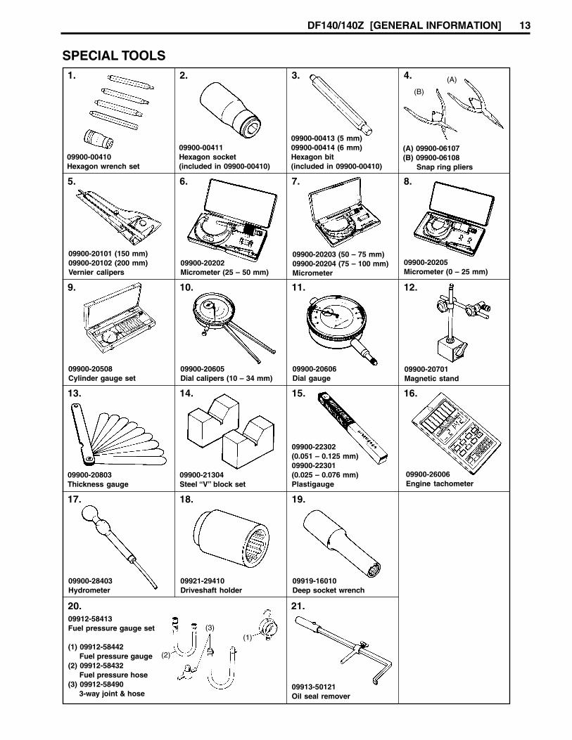
09900-21304Steel “V” block set
09900-22302(0.051 – 0.125 mm)09900-22301(0.025 – 0.076 mm)Plastigauge
09900-20508Cylinder gauge set
1. 2. 3. 4.
5. 6. 7. 8.
9. 10. 11. 12.
13. 14. 15. 16.
17. 18. 19.
20. 21.
09900-20205Micrometer (0 – 25 mm)
09900-20701Magnetic stand
09900-26006Engine tachometer
09912-58413Fuel pressure gauge set
(1) 09912-58442 Fuel pressure gauge(2) 09912-58432 Fuel pressure hose(3) 09912-58490 3-way joint & hose
09900-00410Hexagon wrench set
09900-20101 (150 mm)09900-20102 (200 mm)Vernier calipers
09900-20803Thickness gauge
09900-28403Hydrometer
09900-00411Hexagon socket(included in 09900-00410)
09900-20202Micrometer (25 – 50 mm)
09900-20605Dial calipers (10 – 34 mm)
09921-29410Driveshaft holder
09913-50121Oil seal remover
09900-00413 (5 mm)09900-00414 (6 mm)Hexagon bit(included in 09900-00410)
09900-20203 (50 – 75 mm)09900-20204 (75 – 100 mm)Micrometer
09900-20606Dial gauge
09919-16010Deep socket wrench
(1)
(2)
(3)
(A) 09900-06107(B) 09900-06108 Snap ring pliers
(A)
(B)
SPECIAL TOOLS

14 DF140/140Z [GENERAL INFORMATION]
09916-10910Valve lapper
09916-14910Valve lifter attachment
Solid pilot(Neway N-120-6.0)
26. 27. 29.
30. 31. 32. 33.
35. 36. 37.
38.
28.
39. 41.
44.
09916-54910Handle (N-505)
09916-37810Valve guide reamer(φ φ φ φ φ 6 mm)
09917-87810Valve guide installerattachment
09916-19030Valve lifter
09916-22420Valve seat cutter (60°)(Neway 114)
09916-34542Valve guide reamer handle
09916-57350Valve guide installer
09916-20620Valve seat cutter (45°)(Neway 122)
09916-38210Valve guide reamer(φ φ φ φ φ 11 mm)
09916-77310Piston ring compressor
09916-46020Valve guide remover
43.
34.
09916-20610Valve seat cutter (15°)(Neway 121)
09917-47011Vacuum pump gauge
40.
09916-49040Tappet holder
42.
09916-84511Tweezers
22. 23. 24. 25.
09915-47330Oil filter wrench
09915-64511Compression gauge
09915-67010Compressiongauge hose attachment
09915-64530Compression gauge hose
09915-77311Oil pressure gauge
09915-78211Oil pressure gauge adapter
45.

DF140/140Z [GENERAL INFORMATION] 15
49.
09930-39411Flywheel rotor remover
09930-48720Flywheel holder
50.
09930-39420Rotor remover bolt
47. 48.
51. 52.
55. 56.
59. 60.
63. 64.
67.
09930-30161Propeller shaft remover
09930-99320Digital tester
Pinion bearinginstaller and remover(A) 09951-59910 Pinion bearing installer shaft(B) 01107-08408 Bolt(C) 09951-39914 Pinion bearing plate(D) 09951-19420 Attachment
09930-30102Sliding hammer
09930-76420Timing light
09932-79910Diagnostic harness09932-89910SDS adapter
(A) 09950-69512 Gearcase oil leakage tester(B) Air pump
(A) 18213-74F00 O2 sensor(B) 18498-99E40 Protector
46.
09922-89810Shift lock pin remover
53.
54.
09930-892404-pin connector test cord
09930-89260Injector test cord A
57.
58. 61.
62.
09940-44120Air pressure gauge
09940-44130Attachment
66.
09951-09511Gear adjusting gauge
(A) (B)
(A)
(B) (D)
(C)
(A)
(B)
(A) 09922-59410 Propeller shaft housing installer(B) 09922-59420 Housing installer handle
(A) (B)
09917-98221Valve guide stem sealinstaller attachment
09900-25002Pocket tester
09930-8995044-pin test cord
09944-09420PTT cylinder cap tool
65.
68.
09951-09010Shimming gauge
69. 70.
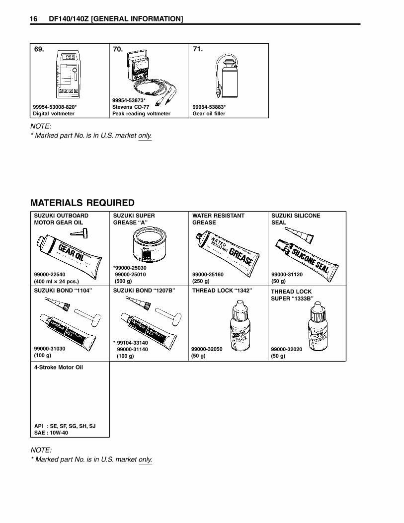
99954-53873*Stevens CD-77Peak reading voltmeter
99954-53883*Gear oil filler
MATERIALS REQUIREDSUZUKI OUTBOARDMOTOR GEAR OIL
99000-22540(400 ml × 24 pcs.)
99000-31030(100 g)
*99000-25030 99000-25010 (500 g)
* 99104-33140 99000-31140 (100 g)
99000-25160(250 g)
99000-32050(50 g)
99000-31120(50 g)
API : SE, SF, SG, SH, SJSAE : 10W-40
SUZUKI SUPERGREASE “A”
WATER RESISTANTGREASE
SUZUKI SILICONESEAL
SUZUKI BOND “1104” SUZUKI BOND “1207B” THREAD LOCK “1342”
4-Stroke Motor Oil
NOTE:* Marked part No. is in U.S. market only.
NOTE:* Marked part No. is in U.S. market only.
99954-53008-820*Digital voltmeter
99000-32020(50 g)
THREAD LOCKSUPER “1333B”
71.
16 DF140/140Z [GENERAL INFORMATION]

ENGINE CONTROLThe specifications of engine control system such as ignitionand fuel injection systems on model DF140 are basically thesame as those on DF90/115.However, the control specifications on DF140 differ from DF90/115 as shown below.
Idling/Trolling speedIdling/Trolling engine speed as controlled by IAC system:• Idling/Trolling engine speed: 700 ± 50 rpm• IAC duty ratio (at idling/trolling): Approximately 30%
NOTE:To adjust idling/trolling engine speed manually on DF140, usethe same procedure as DF90/115 and adjust the speed to 700± 50 rpm with the IAC valve duty set to 30%.
Ignition timingThe ignition timing is controlled within the following range ac-cording to the engine operating condition.• Ignition timing advance range: BTDC 5° – 45°• Ignition timing (at idling/trolling): BTDC 10° ± 5°
Over revolution limterThe over-rev detecting speed is as follows:• DF140: 6500 rpm
SDSThe database specially provided only for DF140 needs to beadded to the Ver. 4 currently used.
FLYWHEEL MAGNETOWhen installing the flywheel magneto, apply a small amount ofengine oil to the threads and seating face of the magneto boltfor lubrication so that the correct tightening torque specifica-tion can be attained securely.
Flywheel bolt : 245 N.m (24.5 kg-m, 177 lb-ft)
DF140/140Z [ENGINE CONTROL] 17
18 DF140/140Z [POWER UNIT]
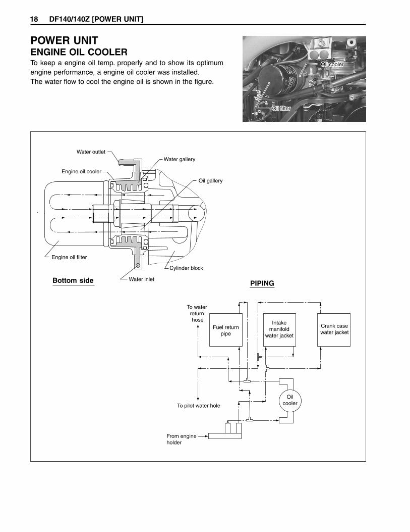
POWER UNITENGINE OIL COOLERTo keep a engine oil temp. properly and to show its optimumengine performance, a engine oil cooler was installed.The water flow to cool the engine oil is shown in the figure.
Bottom side PIPING

Removal1. Remove the STBD side lower cover.2. Using oil filter wrench to loosen the oil filter 1, then remove
engine oil filter and O-ring.
09915-47330: Oil filter wrench
3. Disconnect both inlet 2 and outlet 3 water hoses from en-gine oil cooler.
4. Loosen oil filter stand 4, then remove the oil filter stand andengine oil cooler assembly 5.
NOTE:Use socket wrench to loose the oil filter stand.
Installation1. Install seal ring a to oil cooler assembly.
DF140/140Z [POWER UNIT] 19
2. Place the engine oil cooler assembly 1 to cylinder block.
NOTE:When installing the oil cooler, put a locating pin 2 at the sur-face of rib in the cylinder block as shown in the figure.

20 DF140/140Z [POWER UNIT]
3. Install oil filter stand 3, then tighten filter stand to specifiedtorque.
Oil filter stand: 40 N.m (4.0 kg-m, 29 lb-ft)
Connect inlet 4 and outlet 5 water hoses to each fitting ofengine oil cooler.
4. Screw engine oil filter 6 on by hand until the filter O-ringcontacts the mounting surface.
NOTEBefore fitting oil filter, be sure to oil O-ring.
5. Tighten the engine oil filter 3/4 turn from the point of contactwith the mounting surface using an oil filter wrench.
Engine oil filter: 14 N.m (1.4 kg-m, 10 lb-ft), 3/4 turn
CAMSHAFTThe camshaft for DF140 was specially designed.The height of the cam is different from DF90/115.
••••• Cam heightStandard:
IN. 39.520 – 39.680 mm (1.5560 – 1.5622 in.)EX. 39.320 – 39.480 mm (1.5480 – 1.5543 in.)
Service limit:IN. 39.420 mm (1.5520 in.)EX. 39.220 mm (1.5441 in.)
••••• Camshaft identificationThe camshaft is distinguished by the mark at the top of shaft.DF140 camshaft is marked as shown. Model Mark
DF140 3DF115 2DF90 1
3
I.D mark

PISTON & PISTON RINGPiston and piston ring diameters are different from DF90/115.The dimension of piston has become as the following.
Piston skirt diameter Standard: 85.970 – 85.990 mm (3.3846 – 3.3854 in.)
CYLINDER BLOCKThe cylinder bore is different from DF90/115.The diameter for the cylinder of DF140 has become as the fol-lowing.
Cylinder bore Standard: 86.000 – 86.020 mm (3.3858 – 3.3866 in.)
The shape of piston ring is the same as DF90/115.• 1st ring: Barrel face and nitrogen treatment• 2nd ring: Taper face with under cut and hard chrome plating
NOTE:1st ring differs from 2nd ring in shape and color of surface con-tacting cylinder wall.Distinguish 1st ring from 2nd ring by referring to figure.
DF140/140Z [POWER UNIT] 21
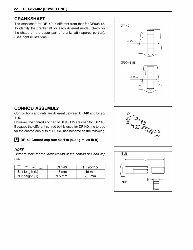
CONROD ASSEMBLYConrod bolts and nuts are different between DF140 and DF90/115.However, the conrod and cap of DF90/115 are used for DF140.Because the different conrod bolt is used for DF140, the torquefor the conrod cap nuts of DF140 has become as the following.
DF140 Conrod cap nut: 40 N.m (4.0 kg-m, 29 lb-ft)
NOTE:Refer to table for the identification of the conrod bolt and capnut.
DF140 DF90/115Bolt length (L) 48 mm 46 mmNut height (H) 9.5 mm 7.5 mm
CRANKSHAFTThe crankshaft for DF140 is different from that for DF90/115.To identify the crankshaft for each different model, check forthe shape on the upper part of crankshaft (tapered portion).(See right illustrations.)
22 DF140/140Z [POWER UNIT]
Lower mount
I.D grooveDF140: GrooveDF90/115: No groove
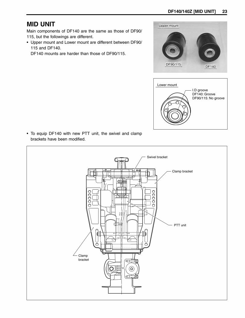
MID UNITMain components of DF140 are the same as those of DF90/115, but the followings are different.• Upper mount and Lower mount are different between DF90/
115 and DF140.DF140 mounts are harder than those of DF90/115.
• To equip DF140 with new PTT unit, the swivel and clampbrackets have been modified.
DF140/140Z [MID UNIT] 23
DF90/115DF140
Upper mount
43 N.m (4.3 kg-m, 31.0 lb-ft)
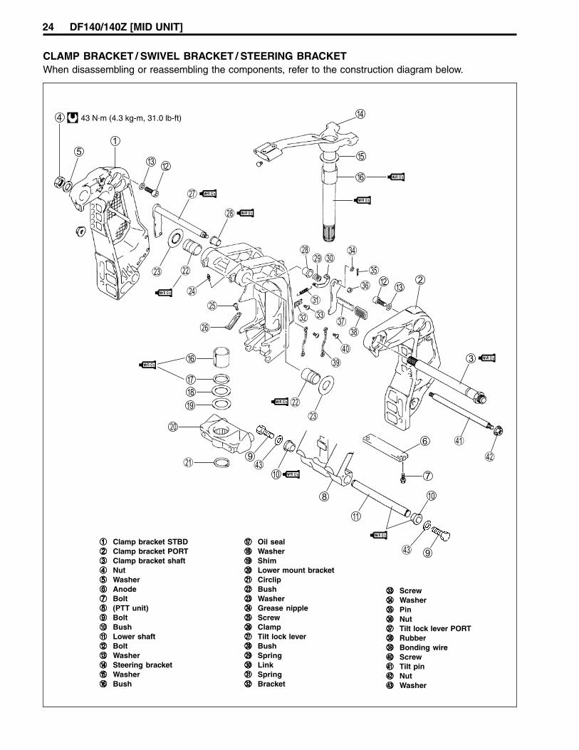
CLAMP BRACKET / SWIVEL BRACKET / STEERING BRACKETWhen disassembling or reassembling the components, refer to the construction diagram below.
11111 Clamp bracket STBD22222 Clamp bracket PORT33333 Clamp bracket shaft44444 Nut55555 Washer66666 Anode77777 Bolt88888 (PTT unit)99999 Bolt00000 BushAAAAA Lower shaftBBBBB BoltCCCCC WasherDDDDD Steering bracketEEEEE WasherFFFFF Bush
GGGGG Oil sealHHHHH WasherIIIII ShimJJJJJ Lower mount bracketKKKKK CirclipLLLLL BushMMMMM WasherNNNNN Grease nippleOOOOO ScrewPPPPP ClampQQQQQ Tilt lock leverRRRRR BushSSSSS SpringTTTTT LinkUUUUU SpringVVVVV Bracket
WWWWW ScrewXXXXX WasherYYYYY PinZZZZZ Nut[[[[[ Tilt lock lever PORT\\\\\ Rubber]]]]] Bonding wire^ Screwaaaaa Tilt pinbbbbb Nutccccc Washer
24 DF140/140Z [MID UNIT]

AIR BLEEDING1. Check that the manual release valve is tightened to the
specified torque.
Manual release valve: 3.5 N.m (0.36 kg-m, 2.6 lb-ft)
Do not over-tighten manual release valve.
Counterclockwise = openClockwise = close
2. Operate the PTT switch, raising and lowering the motor upand down (full tilt position to full trim down position) 4 to 5times.
3. Check oil level, topping off if necessary.4. Reinstall oil filler plug.
POWER TRIM AND TILTPTT unit of DF140 is new design and unit is 3 cylinder (two trimram, one tilt rod) type.
SERVICE PROCEDUREOIL LEVELTo check the oil level:1. Raised the engine to a full-tilt position.2. Lower the manual tilt lock lever 1.3. Remove the oil filler plug 2.4. If oil can be seen at filler plug level, the unit is full.5. If oil level is low, refill with the recommended oil.
Recommended oil:
Dexron automatic transmission fluid or equivalent
To ensure consistent pump operation, do not mix dif-ferent types of oil.
6. Reinstall oil filler plug.
DF140/140Z [POWER TRIM AND TILT] 25
26 DF140/140Z [POWER TRIM AND TILT]
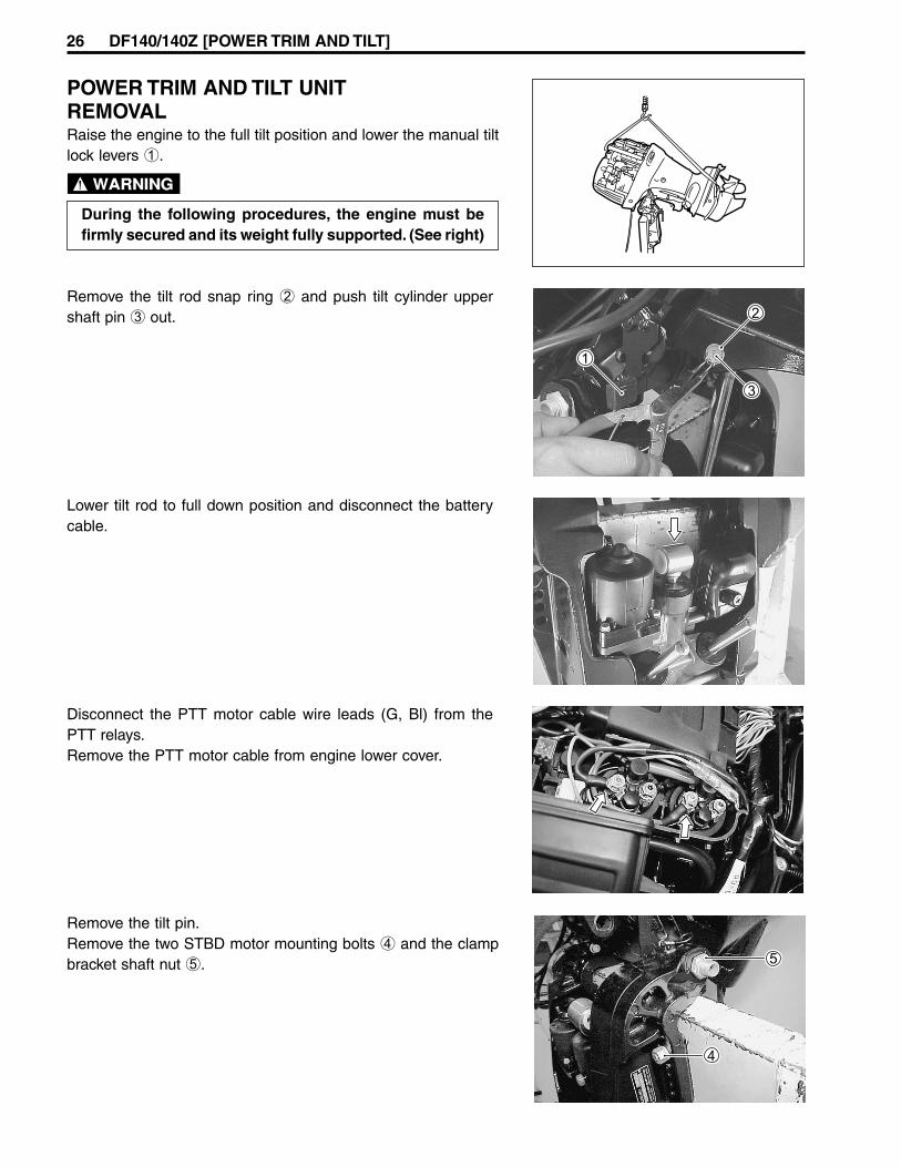
POWER TRIM AND TILT UNITREMOVALRaise the engine to the full tilt position and lower the manual tiltlock levers 1.
During the following procedures, the engine must befirmly secured and its weight fully supported. (See right)
Remove the tilt rod snap ring 2 and push tilt cylinder uppershaft pin 3 out.
Lower tilt rod to full down position and disconnect the batterycable.
Disconnect the PTT motor cable wire leads (G, Bl) from thePTT relays.Remove the PTT motor cable from engine lower cover.
Remove the tilt pin.Remove the two STBD motor mounting bolts 4 and the clampbracket shaft nut 5.
DF140/140Z [POWER TRIM AND TILT] 27
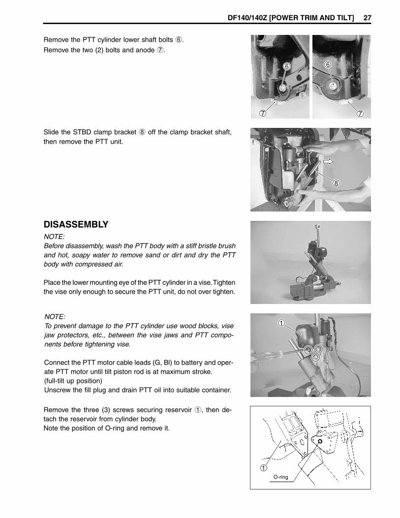
Remove the PTT cylinder lower shaft bolts 6.
Remove the two (2) bolts and anode 7.
DISASSEMBLYNOTE:Before disassembly, wash the PTT body with a stiff bristle brushand hot, soapy water to remove sand or dirt and dry the PTTbody with compressed air.
Place the lower mounting eye of the PTT cylinder in a vise. Tightenthe vise only enough to secure the PTT unit, do not over tighten.
NOTE:To prevent damage to the PTT cylinder use wood blocks, visejaw protectors, etc., between the vise jaws and PTT compo-nents before tightening vise.
Connect the PTT motor cable leads (G, Bl) to battery and oper-ate PTT motor until tilt piston rod is at maximum stroke.(full-tilt up position)Unscrew the fill plug and drain PTT oil into suitable container.
Remove the three (3) screws securing reservoir 1, then de-tach the reservoir from cylinder body.Note the position of O-ring and remove it.
Slide the STBD clamp bracket 8 off the clamp bracket shaft,then remove the PTT unit.

28 DF140/140Z [POWER TRIM AND TILT]
Remove the PTT motor assembly. (See page 33)Note the position of drive joint 3 and O-ring 4, before remov-ing them.
Remove the manual release valve snap ring 5, then unscrewthe manual release valve 6.
Remove the three (3) screws securing the PTT pump case 7,then detach the PTT pump case from PTT cylinder body.Note the position of O-rings and orifices collars, before remov-ing them.
Using special tool, unscrew the PTT cylinder head.
09944-09420: PTT cylinder cap tool
PTTmotor
A: Orifice collar (with ball valve)B: Orifice collar (with filter and ball valve)C: Orifice collar

DF140/140Z [POWER TRIM AND TILT] 29
Disassembly of tilt rod/piston assemblyUnscrew the piston retaining nut from the bottom of the tilt rodand remove the washer.Carefully retain and account for four shock valves, each com-posed of spring, rod and ball.
Remove the piston assembly and PTT cylinder head from thetilt rod by sliding them down and off the rod end.
Disassembly of trim rod / piston assemblyUsing special tool, unscrew the trim cylinder head.
09944-09420: PTT cylinder cap tool
Pull the tilt rod/piston assembly 1 out of the cylinder body.Remove the free piston 2 from the cylinder body.
Pull the trim rod/piston assembly out of the trim cylinder.
30 DF140/140Z [POWER TRIM AND TILT]
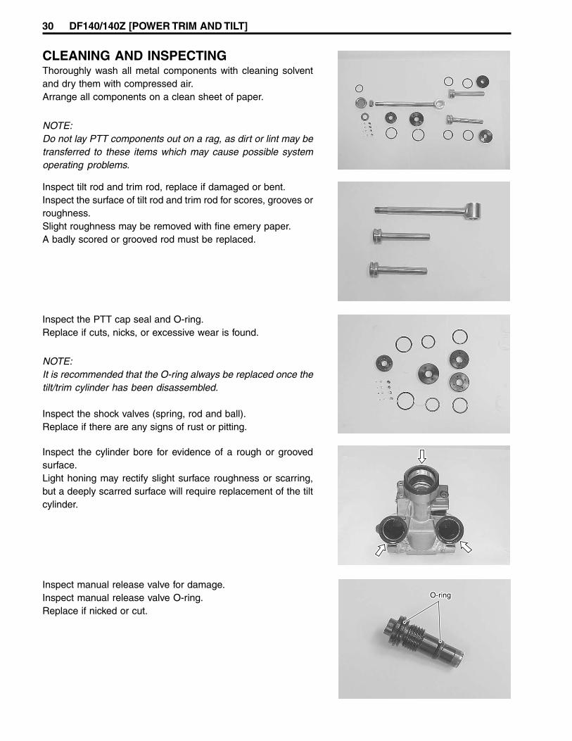
Inspect tilt rod and trim rod, replace if damaged or bent.Inspect the surface of tilt rod and trim rod for scores, grooves orroughness.Slight roughness may be removed with fine emery paper.A badly scored or grooved rod must be replaced.
Inspect the PTT cap seal and O-ring.Replace if cuts, nicks, or excessive wear is found.
NOTE:It is recommended that the O-ring always be replaced once thetilt/trim cylinder has been disassembled.
Inspect the shock valves (spring, rod and ball).Replace if there are any signs of rust or pitting.
Inspect the cylinder bore for evidence of a rough or groovedsurface.Light honing may rectify slight surface roughness or scarring,but a deeply scarred surface will require replacement of the tiltcylinder.
Inspect manual release valve for damage.Inspect manual release valve O-ring.Replace if nicked or cut.
CLEANING AND INSPECTINGThoroughly wash all metal components with cleaning solventand dry them with compressed air.Arrange all components on a clean sheet of paper.
NOTE:Do not lay PTT components out on a rag, as dirt or lint may betransferred to these items which may cause possible systemoperating problems.

DF140/140Z [POWER TRIM AND TILT] 31
REASSEMBLYAssembly is reverse order of disassembly with special atten-tion to following steps.
• Do not reuse O-rings after removal, always use newO-rings.
• Lubricate all components and O-rings with PTT fluidbefore assembly.
• Do not reuse PTT fluid, always refill with new fluid.
TILT RODWhen tightening the piston retaining nut on the tilt rod piston,apply Thread lock 1342 to the threads.Tighten the nut to specified torque.
99000-32050: Thread Lock 1342
Piston retaining nut: 100 N.m (10 kg-m, 72 lb-ft)
Installing tilt rod / pistonPour 100 ml of PTT fluid into cylinder.Insert the free piston into cylinder and push it down to the bot-tom of the cylinder.
Pour PTT fluid into the cylinder until it is topped off.Insert the tilt rod/piston into cylinder and thread the tilt cylinderhead by hand until fully seated.
Tighten the cylinder head to specified torque using special tool.
Tilt cylinder head: 160 N.m (16 kg-m, 115.7 lb-ft)
09944-09420: PTT cylinder cap tool
Cylinder
Free piston
Top OFF

32 DF140/140Z [POWER TRIM AND TILT]
TRIM RODPour PTT fluid into the trim cylinder until it is topped off.Insert the trim rod/piston assembly into cylinder and thread thetrim cylinder head by hand until fully seated.
Tighten the trim cylinder head to specified torque using specialtool.
Trim cylinder head: 78 N.m (7.8 kg-m, 56.4 lb-ft)
09944-09420: PTT cylinder cap tool
PTT PUMP CASEInstall five (5) O-rings and orifice collars to PTT cylinder body.
NOTE:Lubricate O-rings with PTT fluid before installing PTT cylinderbody.
Install PTT pump case, then tighten three (3) screws to speci-
fied torque.
PTT pump case screw: 3.5 N.m (0.35 kg-m, 2.5 lb-ft)
MANUAL RELEASE VALVEOil and install the manual release valve 1.Tighten the valve to specified torque.Install snap ring 2.
Manual release valve: 3.5 N.m (0.36 kg-m, 2.6 lb-ft)
PTT MOTORSee the PTT Motor Installation section on page 36.
RESERVOIRInstall O-ring and reservoir, then tighten bolts to specified torque.
Reservoir bolt: 5 N.m (0.5 kg-m, 3.5 lb-ft)
AIR BLEEDING• Pour recommended PTT fluid in to reservoir until specified
level.• Perform the air bleeding procedure.
For air bleeding, see page 25.

DF140/140Z [POWER TRIM AND TILT] 33
PTT MOTORRemoval
NOTE:Before removing PTT motor, wash the PTT body with a stiffbristle brush and hot, soapy water to remove sand or dirt anddry the PTT body with compressed air.
Place the lower mounting eye of the PTT cylinder in a vise.Tighten the vise only enough to secure the PTT unit, do notover tighten.
NOTE:To prevent damage to the PTT cylinder use wood blocks, visejaw protectors, etc., between the vise jaws and PTT compo-nents before tightening vise.
Remove the four (4) screws securing the PTT motor to the PTTpump case.
Detach the PTT motor from PTT pump case.Note the position of drive joint 1 and O-ring 2 and removethem.
PTT motor DisassemblyFor correct assembly, scribe an alignment mark on the field caseand brush holder.Slide cable protector tube upward.Remove the screw securing the motor cable holder 1, thenslide motor cable holder and grommets 2 out as shown infigure.
Protectortube
1
1
2
PTTMotor

34 DF140/140Z [POWER TRIM AND TILT]
Remove the two (2) screws 3 securing the field case to thebrush holder.
Slide the field case upward and away from the brush holder.
NOTE:When separating field case from brush holder, proceed by push-ing PTT motor cables into brush holder side.
Disconnect PTT motor cables from brush holder.Remove armature from field case.Note the position of the O-ring encircling the brush holder.
3
InspectionArmature and CommutatorCheck for continuity between the commutator and the armaturecore/shaft.Replace armature if continuity is indicated.
09930-99320: Digital tester
Tester range: (Continuity)
Check continuity between the adjacent commutator segments.Replace armature if no continuity is indicated.
DF140/140Z [POWER TRIM AND TILT] 35
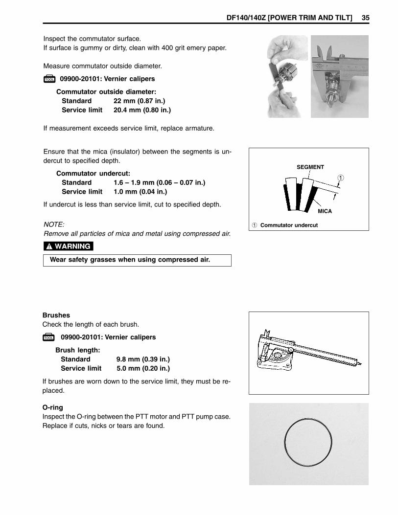
Inspect the commutator surface.If surface is gummy or dirty, clean with 400 grit emery paper.
Measure commutator outside diameter.
09900-20101: Vernier calipers
Commutator outside diameter:Standard 22 mm (0.87 in.)Service limit 20.4 mm (0.80 in.)
If measurement exceeds service limit, replace armature.
Ensure that the mica (insulator) between the segments is un-dercut to specified depth.
Commutator undercut:Standard 1.6 – 1.9 mm (0.06 – 0.07 in.)Service limit 1.0 mm (0.04 in.)
If undercut is less than service limit, cut to specified depth.
NOTE:Remove all particles of mica and metal using compressed air.
Wear safety grasses when using compressed air.
SEGMENT
MICA
1
1 Commutator undercut
BrushesCheck the length of each brush.
09900-20101: Vernier calipers
Brush length:Standard 9.8 mm (0.39 in.)Service limit 5.0 mm (0.20 in.)
If brushes are worn down to the service limit, they must be re-placed.
O-ringInspect the O-ring between the PTT motor and PTT pump case.Replace if cuts, nicks or tears are found.

36 DF140/140Z [POWER TRIM AND TILT]
AssemblyAssembly is reverse of disassembly with special attention tofollowing steps.
• Install armature to brush holder first.When installing the armature, exercise care not to break thebrushes.
• Match up previously scribed alignment marks.• When assembling field case to brush holder, proceed by pull-
ing PTT motor cables out of field case.• Apply silicone seal to PTT motor cable holder and grom-
mets and install cable holder screw.
O-ring
PTT motor installationInstallation is reverse of removal with special attention to fol-lowing steps.
• Ensure that the drive joint 1 is aligned and firmly insertedinto the gear pump assembly.
• Fit O-ring 2 to PTT motor.• Check the level of PTT fluid contained in the PTT pump case.
If level is low, add recommended PTT fluid until level withmating surface of PTT motor.
• Ensure that the faces of the PTT motor and pump unit arefree of dirt or debris.When attaching the PTT motor to the PTT pump case, en-sure that the tip of armature shaft fits firmly into the drive joint1.
• Tighten the four (4) screws to specified torque.
PTT motor screw: 5 N.m (0.5 kg-m, 3.6 lb-ft)
• Pour recommended PTT fluid into reservoir until specifiedlevel.
• Perform the air bleeding procedure.For air bleeding, see page 25.

DF140/140Z [POWER TRIM AND TILT] 37
INSTALLATIONInstallation is reverse order of removal with special attention tothe following steps.
Lower tilt rod to full down position.
Place the PTT unit in position, then install the clamp bracket.Tighten the clamp bracket shaft nut to specified torque.
Clamp bracket shaft nut:43 N.m (4.3 kg-m, 31.0 lb-ft)
Apply Water Resistant Grease to the tilt cylinder lower shaftand lower shaft bushes.Install bushes 1 and cylinder lower shaft 2 to PTT unit.
99000-25160: Water Resistant Grease
Tighten lower shaft bolts 4, pre-coated with thread lock, tospecified torque.
99000-32050: Thread Lock 1342
Cylinder lower shaft bolt:50 N.m (5.0 kg-m, 36.0 lb-ft)
Install anode 5, then tighten bolts securely.
38 DF140/140Z [POWER TRIM AND TILT]
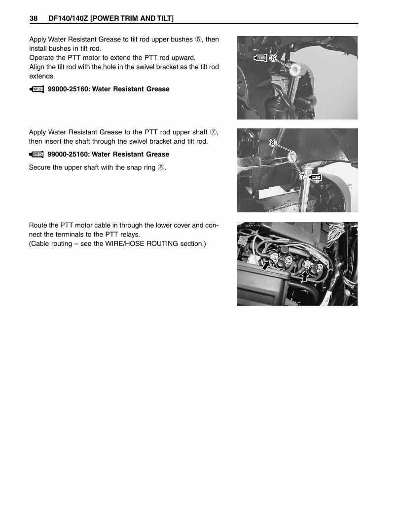
Apply Water Resistant Grease to the PTT rod upper shaft 7,then insert the shaft through the swivel bracket and tilt rod.
99000-25160: Water Resistant Grease
Secure the upper shaft with the snap ring 8.
Route the PTT motor cable in through the lower cover and con-nect the terminals to the PTT relays.(Cable routing – see the WIRE/HOSE ROUTING section.)
Apply Water Resistant Grease to tilt rod upper bushes 6, theninstall bushes in tilt rod.Operate the PTT motor to extend the PTT rod upward.Align the tilt rod with the hole in the swivel bracket as the tilt rodextends.
99000-25160: Water Resistant Grease
DF140/140Z [POWER TRIM AND TILT] 39
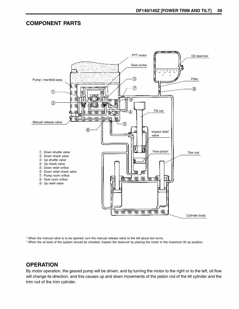
COMPONENT PARTS
1 Down shuttle valve2 Down check valve3 Up shuttle valve4 Up check valve5 Down relief orifice6 Down relief check valve7 Pump room orifice8 Tank room orifice9 Up relief valve
* When the manual valve is to be opened, turn the manual release valve to the left about two turns.* When the oil level of the system should be checked, inspect the reservoir by placing the motor in the maximum tilt up position.
OPERATIONBy motor operation, the geared pump will be driven, and by turning the motor to the right or to the left, oil flowwill change its direction, and this causes up and down movements of the piston rod of the tilt cylinder and thetrim rod of the trim cylinder.

40 DF140/140Z [POWER TRIM AND TILT]
TRIM & TILT UP(1) When the PTT switch is operated in the “UP” position, the motor and gear pump will rotate in a clockwise
direction.(2) Pressurized oil will open “Up” check valve A and the oil will flow through “Up” shuttle valve B to the
“Down” shuttle valve E. Following operation of valve E, “Down” check valve D will open mechanically.(3) Pressurized oil flows through the “Up” check valve A to the bottom of the trim and tilt cylinders, thereby
pushing the trim and tilt pistons upward.(4) Residual oil in the upper area of the tilt cylinder H is returned to the pump through “Down” check valve D.(5) Any oil in the area above both trim cylinder pistons will be returned to the reservoir.(6) Oil will then flow from the reservoir to the pump to stabilize the balance of the oil volumes.(7) When the engine is fully tilted up, oil pressure will correspondingly increase in the lower chamber of the tilt
and trim cylinders. But, to protect the PTT unit from excessively high pump pressure, the “Up” relief valveG begins to open.

DF140/140Z [POWER TRIM AND TILT] 41
TILT DOWN / TRIM IN(1) When the PTT switch is operated in the “DOWN” position, the motor and gear pump will rotate in a
counterclockwise direction.(2) The oil pressure will open the “Down” check valve D and oil will be forced through the “Down” shuttle valve
E. When the oil reaches “Up” shuttle valve B, the “Up check valve A will begin to open mechanically.(3) The pressurized oil flows through “Down” check valve D and then enters the upper area of the tilt cylinder.
This thereby forces the tilt rod piston downward.(4) When the swivel bracket contacts the trim rams, this pressure forces the trim pistons downward and oil
from the reservoir is then able to enter the area above both trim rod pistons.(5) Oil from the lower area of the trim and tilt cylinders now returns to the pump through “Up” check valve A.(6) Throughout the tilt action operation range, there is a difference in oil volume between the upper and lower
chambers of the tilt cylinder, and any surplus oil is therefore directed to the reservoir by means of the“Down” relief orifice H.
(7) Throughout trim operation range, oil will be discharged from the bottom of all three cylinders and thepump will only supply oil to the tilt cylinder. Excess oil is then vented to the reservoir through the “Down”relief orifice H.
(8) To prevent damage from excessive oil pressure when all three rods are fully retraced, this pressure isrelieved through the “Down” relief orifice H.

42 DF140/140Z [POWER TRIM AND TILT]
TILT SYSTEM PRESSURE RELIEF(1) If engine speed exceeds approx. 1500 RPM when operating in shallow water drive mode, oil pressure will
increase underneath the tilt piston. The relief valve C (incorporated in the manual release valve K) willthen open.
(2) The oil below the tilt piston will then flow to the reservoir through the relief valve C.(3) As the power of the engine continues to exert downward force on the tilt piston, this will open “Down”
check valve D, thereby allowing oil from the reservoir to flow into the chamber above the tilt piston.(4) In this way, high internal pressure is relieved and the engine will slowly tilt downward until it reaches the
highest position in the Trim range.
THERMAL EXPANSION RELIEF(1) High ambient temperature will, through thermal expansion, induce a build-up of oil pressure inside the
PTT unit.(2) Expansion of the oil and the resulting high pressure will open the relief valve C, thereby providing unit
protection by directing oil back to the reservoir.Expanded oil in the tilt cylinder upper chamber will return to reservoir passing through impact relief valveI free piston check valve J thermal relief valve C.

DF140/140Z [POWER TRIM AND TILT] 43
SHOCK ABSORBER CIRCUITThis incorporated safety feature is for protection of the gearcase and prevention of internal PTT pressurebuild-up in the event of an impact.(1) The pressure from a sudden impact will make impact relief valve I open, allowing oil from the upper area
of the tilt cylinder to flow into the area between the tilt rod piston and the free piston. The tilt rod will thenextend.
(2) When the moment of impact has passed, the PTT DOWN switch must be activated to return the engine towithin the normal trim range. When the switch is pressed, the oil between the piston and free piston will bedirected to the cylinder upper chamber via the return valve below the tilt piston.

44 DF140/140Z [POWER TRIM AND TILT]
MANUAL RELEASE CIRCUIT (DOWN MODE)(1) By opening the manual release valve K, the engine can be lowered manually to a running position. Oil
underneath the trim and tilt pistons will be directed through this valve into the area above the tilt rodpiston.
(2) The volume of oil flowing from under the trim rod pistons will be larger than the area above the tilt rodpiston can accommodate. Excess oil therefore returns through the manual release valve K to the reser-voir.

DF140/140Z [POWER TRIM AND TILT] 45
MANUAL RELEASE CIRCUIT (UP MODE)(1) With the manual release valve K open, the engine can also be raised manually to the fully tilted position.(2) Oil from the upper chamber of the tilt cylinder will flow through valve K into the lower chamber of the
cylinder.(3) The upward movement of the piston rod will increase the cylinder area beneath it, thereby allowing oil
from the reservoir to flow into this area.

46 DF140/140Z [NORMAL ROTATION LOWER UNIT]
LOWER UNIT (Normal rotation model)
REMOVAL AND INSTALLATIONRefer to the procedures in DF90/115 service manual.
Always disconnect the battery cable, before removinglower unit.
DISASSEMBLYPlace a drain pan under the oil drain plug.Remove oil drain plug 1 first then oil level plug 2 and allowgear oil to drain.Inspect oil for water, contaminates or metal.
Remove cotter pin 2 from propeller nut and remove propellernut 3.Remove washer 4, spacer 5, propeller 6 and stopper 7 fromthe propeller shaft.
To prevent injury from propeller blades, wear glovesand place a block of wood between the anti-cavitationplate and the propeller blade tips to lock the propellerin place.
Loosen the four (4) bolts 1, then remove the water pump case2.

DF140/140Z [NORMAL ROTATION LOWER UNIT] 47
Remove the impeller 3, impeller key 6, pump under plate 4and dowel pins 5.Keep the impeller key 6 for reuse and discard the plate gas-ket.
Remove three (3) bolts 1 and shift rod guide housing assem-bly 2.
Remove the two (2) bolts 1 securing the propeller shaft bear-ing housing to the gearcase.
Using special tools, draw out the propeller shaft bearing hous-ing.Remove the propeller shaft and bearing housing assembly.
09930-30102: A Sliding hammer09930-30161: B Propeller shaft remover
Hold the pinion nut securely, then fit special tool to the driveshaftand loosen the pinion nut.
09921-29410: Driveshaft holder
A
B

48 DF140/140Z [NORMAL ROTATION LOWER UNIT]
Lift out driveshaft assembly 4.Remove the driveshaft collar 5, washer 6, wave washer 7,washer (with tab) 8 and washer 9 from driveshaft.
Unscrew the four (4) bolts 1 securing driveshaft oil seal hous-ing 2, then remove oil seal housing and pinion shim 3.
Remove the pinion gear 1.Remove the forward gear 2 and thrust bearing 3.
Remove the bearing thrust washer 4 and back-up shim 5.
Remove the forward gear bearing housing 6.Account for dowel pin 7.
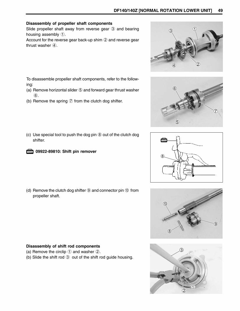
DF140/140Z [NORMAL ROTATION LOWER UNIT] 49
(c) Use special tool to push the dog pin 8 out of the clutch dogshifter.
09922-89810: Shift pin remover8
To disassemble propeller shaft components, refer to the follow-ing:(a) Remove horizontal slider 5 and forward gear thrust washer
6.(b) Remove the spring 7 from the clutch dog shifter.
Disassembly of propeller shaft componentsSlide propeller shaft away from reverse gear 3 and bearinghousing assembly 1.Account for the reverse gear back-up shim 2 and reverse gearthrust washer 4.
(d) Remove the clutch dog shifter 9 and connector pin 0 frompropeller shaft.
Disassembly of shift rod components(a) Remove the circlip 1 and washer 2.(b) Slide the shift rod 3 out of the shift rod guide housing.

50 DF140/140Z [NORMAL ROTATION LOWER UNIT]
(c) Remove the detent ball 4 and spring 5.
(d) Remove the pin 6 and shifter yoke 7.

DF140/140Z [NORMAL ROTATION LOWER UNIT] 51
54 N.m (5.5 kg-m, 39.8 lb-ft)
ASSEMBLYAssembly is reverse of disassembly with special attention to following steps.
1 1 1 1 1 Oil seal2 2 2 2 2 Shift rod guide housing3 3 3 3 3 Bolt4 4 4 4 4 Ball5 5 5 5 5 Spring6 6 6 6 6 Notch plate7 7 7 7 7 O-ring8 8 8 8 8 Washer9 9 9 9 9 Circlip0 0 0 0 0 Seal coverA A A A A Shift rodB B B B B Yoke, shifterC C C C C PinD D D D D Horizontal sliderE E E E E MagnetoF F F F F GrommetG G G G G Water pump caseH H H H H PinI I I I I BoltJ J J J J KeyK K K K K Water pump impellerL L L L L Pump case under panelM M M M M GasketN N N N N Exhaust sealO O O O O Exhaust seal plateP P P P P UnionQ Q Q Q Q HoseR R R R R NippleS S S S S Gear caseT T T T T BoltU U U U U BoltV V V V V PinW W W W W AnodeX X X X X WasherY Y Y Y Y BoltZ Z Z Z Z Trim tab[ [ [ [ [ Bolt\ \ \ \ \ Screw] ] ] ] ] Water filter PORT^ ^ ^ ^ ^ Water filter STBD

52 DF140/140Z [NORMAL ROTATION LOWER UNIT]
a a a a a Driveshaftb b b b b Oil sealc c c c c Boltd d d d d Oil seal housinge e e e e O-ringf f f f f Shimg g g g g Bearingh h h h h Washeri i i i i Washerj j j j j Wave washerk k k k k Washerl l l l l Driveshaft collar
m m m m m Plugn n n n n Gasketo o o o o Bearingp p p p p F-gear bearing housingq q q q q F-gear bearingr r r r r Back-up shims s s s s Thrust washert t t t t F-gear thrust bearingu u u u u Forward gearv v v v v Pinion gearw w w w w Pinion nutx x x x x Thrust washery y y y y Connector pinz z z z z Clutch dog shifter Dog pin| | | | | Dog spring
Propeller shaft~ ~ ~ ~ ~ Thrust washer; ; ; ; ; Reverse gear: : : : : Shim, , , , , O-ring. . . . . Bearing/ / / / / Propeller shaft bearing housing+ + + + + Bolt* * * * * Bearing< < < < < Oil seal> > > > > Washer? ? ? ? ? Retaining ring„ „ „ „ „ Stopper… … … … … Propeller† † † † † Propeller bush‡ ‡ ‡ ‡ ‡ Spacerˆ ˆ ˆ ˆ ˆ Washer‰ ‰ ‰ ‰ ‰ NutŠ Š Š Š Š Pin@@@@@‹ ‹ ‹ ‹ ‹ Dowel pin@@@@@
120 N.m(12 kg-m, 86.8 lb-ft)
20 N.m(2.0 kg-m,14.5 lb-ft)
13 N.m (1.3 kg-m, 9.5 lb-ft)
13 N.m(1.3 kg-m,9.5 lb-ft)
55 N.m (5.5 kg-m, 40.0 lb-ft)
DF140/140Z [NORMAL ROTATION LOWER UNIT] 53
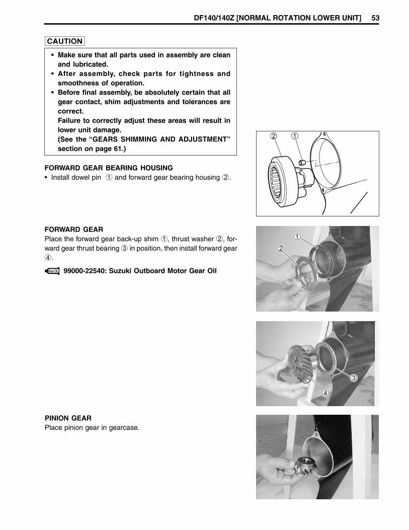
• Make sure that all parts used in assembly are cleanand lubricated.
• After assembly, check parts for tightness andsmoothness of operation.
• Before final assembly, be absolutely certain that allgear contact, shim adjustments and tolerances arecorrect.Failure to correctly adjust these areas will result inlower unit damage.(See the “GEARS SHIMMING AND ADJUSTMENT”section on page 61.)
FORWARD GEAR BEARING HOUSING• Install dowel pin 1 and forward gear bearing housing 2.
PINION GEARPlace pinion gear in gearcase.
FORWARD GEARPlace the forward gear back-up shim 1, thrust washer 2, for-ward gear thrust bearing 3 in position, then install forward gear4.
99000-22540: Suzuki Outboard Motor Gear Oil
54 DF140/140Z [NORMAL ROTATION LOWER UNIT]
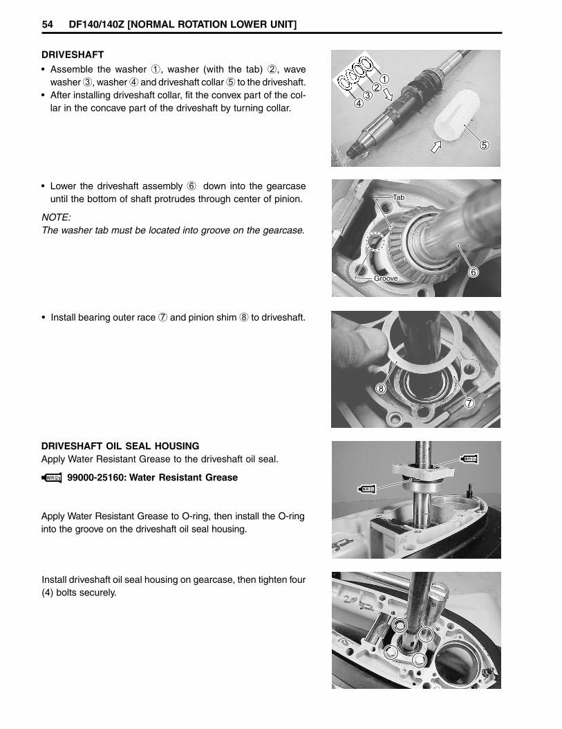
DRIVESHAFT
DRIVESHAFT OIL SEAL HOUSINGApply Water Resistant Grease to the driveshaft oil seal.
99000-25160: Water Resistant Grease
Apply Water Resistant Grease to O-ring, then install the O-ringinto the groove on the driveshaft oil seal housing.
• Assemble the washer 1, washer (with the tab) 2, wavewasher 3, washer 4 and driveshaft collar 5 to the driveshaft.
• After installing driveshaft collar, fit the convex part of the col-lar in the concave part of the driveshaft by turning collar.
• Lower the driveshaft assembly 6 down into the gearcaseuntil the bottom of shaft protrudes through center of pinion.
NOTE:The washer tab must be located into groove on the gearcase.
• Install bearing outer race 7 and pinion shim 8 to driveshaft.
Install driveshaft oil seal housing on gearcase, then tighten four(4) bolts securely.

DF140/140Z [NORMAL ROTATION LOWER UNIT] 55
PINION NUTApply Thread Lock 1342 to the threads of the pinion nut beforethreading it onto the driveshaft.Tighten nut to the specified torque.
Pinion nut: 120 N.m (12 kg-m, 86.8 lb-ft)
99000-32050: Thread Lock 1342
09921-29410: Driveshaft holder
CHECKING DRIVESHAFT THRUST PLAYBefore installing reverse gear, driveshaft thrust play shouldchecked.(See the “GEARS-SHIMMING AND ADJUSTMENT/CHECK-ING DRIVESHAFT THRUST PLAY” section on page 62.)
09951-09511: Gear adjusting gauge
PROPELLER SHAFTSlide the clutch dog shifter 2 onto the propeller shaft 1.
NOTE:For correct installation the side of the clutch dog shifter whichmust face towards reverse gear is marked with the letter “R”.
Insert the connector pin 3 into propeller shaft.
Align the holes in the shifter dog and connector pin and thenslide the dog pin 4 through both dog and connector pin.
Install the dog pin retaining spring 5, ensuring that it fits snuglyinto the groove on the dog shifter.

56 DF140/140Z [NORMAL ROTATION LOWER UNIT]
PROPELLER SHAFT / BEARING HOUSINGAssemble the propeller shaft in the following sequence:forward thrust washer 5, reverse thrust washer 1, reversegear 2, reverse gear back-up shim 3 and propeller shaft hous-ing 4.
99000-25160: Water Resistant Grease
99000-22540: Suzuki Outboard Motor Gear Oil
Assemble horizontal slider 6 to connector pin.
Using special tools, install the propeller shaft and housing as-sembly in the gear case.
09922-59410: Propeller shaft housing installer09922-59420: Housing Installer Handle
When the housing is fully seated, tighten both retaining boltsto the specified torque.
Bearing housing bolt: 20 N.m (2.0 kg-m, 14.5 lb-ft)
RECHECKING DRIVESHAFT THRUST PLAYRecheck the driveshaft thrust play.This should not be less than previously checked. If less, re-duce the number/thickness of reverse gear back-up shims.
09951-09511: Gear adjusting gauge

DF140/140Z [NORMAL ROTATION LOWER UNIT] 57
Frontdirection
Shifter yoke
CHECKING PROPELLER SHAFT THRUST PLAYSee the “GEARS - SHIMMING AND ADJUSTMENT/CHECK-ING PROPELLER SHAFT THRUST PLAY” section on page 65.
SHIFT ROD GUIDE HOUSING• Install the spring 1 and detent ball 2 into shift rod guide
housing.• Apply Water Resistant Grease to the shift rod oil seal.
• Install shift rod 3 and washer 4 into the shift rod guidehousing 5, then secure it with the snap ring 6.
NOTE:Before install the shift unit (Shift rod guide housing assembly),be sure to put the horizontal slider in the neutral position.
• Apply Water Resistant Grease to the shift rod guide housingO-ring.
NOTE:
Before install the shift unit (Shift rod guide housing assembly),bring shifter yoke to the neutral position by turning shift rodright or left.
1. Horizontal slider2. F. Gear bearing housing3. Shift rod center
2
3
1

58 DF140/140Z [NORMAL ROTATION LOWER UNIT]
Horizontal slider
Shifter yoke
• Install the shift rod guide housing assembly 7 by aligningthe shifter yoke with the groove in the horizontal slider, thentighten three (3) housing bolts securely.
• Shift the shift rod from Neutral through Forward and Reverse tocheck proper gear engagement.
• Apply enough Water Resistant Grease on oil seal before put-ting seal cover 8 so that there is no space between them.
DF140/140Z [NORMAL ROTATION LOWER UNIT] 59
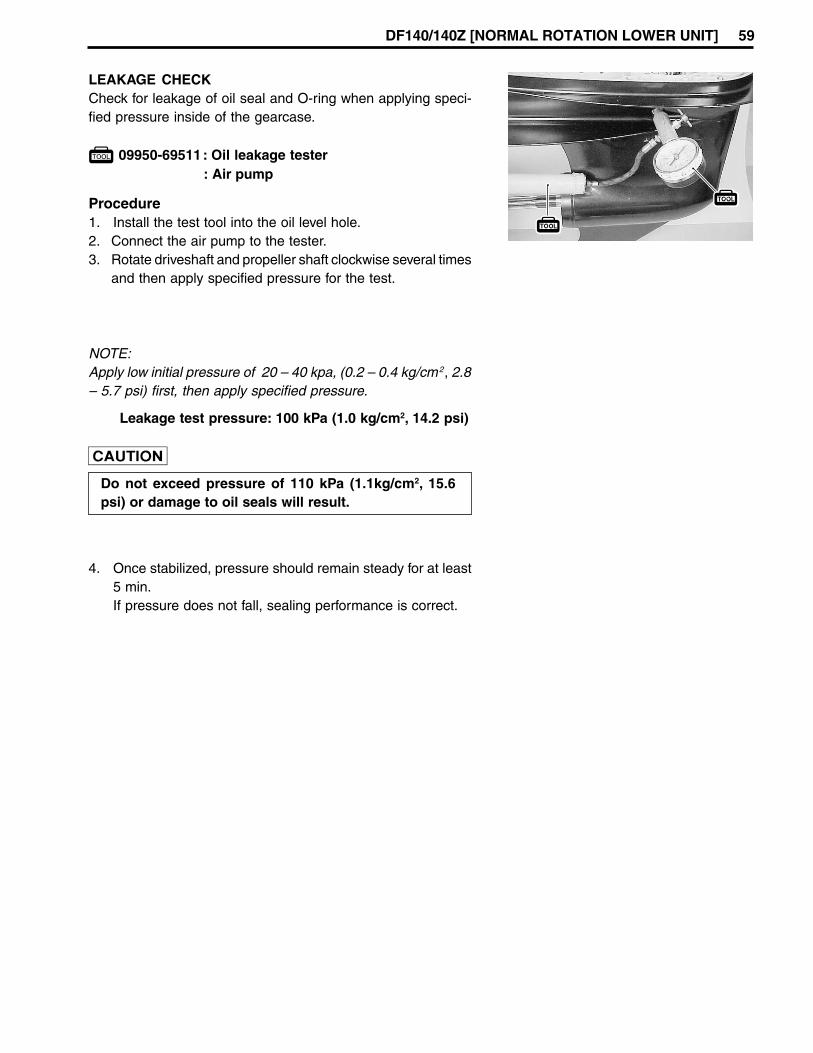
LEAKAGE CHECKCheck for leakage of oil seal and O-ring when applying speci-fied pressure inside of the gearcase.
09950-69511: Oil leakage tester: Air pump
Leakage test pressure: 100 kPa (1.0 kg/cm2, 14.2 psi)
NOTE:Apply low initial pressure of 20 – 40 kpa, (0.2 – 0.4 kg/cm2, 2.8– 5.7 psi) first, then apply specified pressure.
Do not exceed pressure of 110 kPa (1.1kg/cm2, 15.6psi) or damage to oil seals will result.
Procedure1. Install the test tool into the oil level hole.2. Connect the air pump to the tester.3. Rotate driveshaft and propeller shaft clockwise several times
and then apply specified pressure for the test.
4. Once stabilized, pressure should remain steady for at least5 min.If pressure does not fall, sealing performance is correct.

60 DF140/140Z [NORMAL ROTATION LOWER UNIT]
WATER PUMP (Impeller & Case)Place the dowel pins 1, under panel gasket 2 and under panel3 into position.
Insert the key 4 in the driveshaft and slide the impeller 5 ontodriveshaft, ensuring that key and keyway are aligned.
Install the pump case 6 while rotating driveshaft clockwise toflex the impeller vanes in the correct direction.
Securely tighten the four (4) pump case bolts to the specifiedtorque.
Pump case bolt: 20 N.m (2.0 kg-m, 14.5 lb-ft)
PROPELLER INSTALLATIONInstall propeller stopper 1 onto propeller shaft, then slide onthe propeller 2.Fit spacer 3, washer 4 and nut 5, then tighten nut to speci-fied torque.Push cotter pin 6 through nut and shaft, then bend to secure.
99000-25160: Water Resistant Grease
Propeller nut: 55 N.m (5.5 kg-m, 40.0 lb-ft)
GEAR OILFill the gearcase with specified gear oil for initial testing andrecheck the level after 10 minutes.Top up if necessary.
99000-22540: Suzuki Outboard Motor Gear Oil

DF140/140Z [NORMAL ROTATION LOWER UNIT] 61
LOWER UNIT GEARS-SHIMMING AND ADJUSTMENT (Normal rotation model)If lower unit has been rebuilt or has had components replaced, shimming for correct gear contact and back-lash will have to be adjusted to ensure smooth, reliable operation of gears.
1
Numericalindex/item
Availablethickness(mm)
DesignspecificationThickness (mm)
Pinion gearback up shim
0.60, 0.65, 0.70, 0.75, 0.80,0.85, 0.90, 0.95, 1.00, 1.05,1.10, 1.15
1.0
Forward gearback up shim 1.1
Forward gearthrust washer 9.0 9.0
Reverse gearthrust washer 1.5
Reverse gearback up shim 1.5
2
3
4
5
Shim/Washer & Mounting position
0.60, 0.65, 0.70, 0.75, 0.80,0.85, 0.90, 0.95, 1.00
1.5, 1.7, 1.9, 2.1, 2.3, 2.4,2.6, 2.7, 2.8
1.0, 1.1, 1.2, 1.3, 1.4, 1.5, 1.6
PINION GEAR BACK-UP SHIM ADJUSTMENT(1)Position the shimming gauge A horizontally in a vise and
tighten vise securely.
09951-09010: Shimming gauge
(2) Assemble the bearing outer race 1, back-up shim 2 anddriveshaft oil seal housing 3 to the driveshaft.
NOTE:Use a thinner pinion back-up shim 2 than the standard shimso that a clearance B exists.
(3) Insert the driveshaft through the shimming gauge A open-ing and then install pinion gear 4 and nut 5 to the driveshaft,tighten pinion nut.
Pinion nut: 120 N.m (12 kg-m, 86.8 lb-ft)
(4) Install oil seal housing to shimming gauge with bolts 6.(5)Depress and hold driveshaft so that driveshaft bearing is
firmly seated in bearing outer race.
62 DF140/140Z [NORMAL ROTATION LOWER UNIT]
(6)Hold driveshaft against oil seal housing 3 while measuringclearance B between gauge and flat edge of pinion gear 4with thickness gauge, measured clearance plus shim 2 isthe total shim thickness to be used in gear housing reas-sembly for correct pinion gear position.
FORWARD GEAR BACK-UP SHIM ADJUSTMENTFollow the procedure below to adjust forward gear/pinion gear.
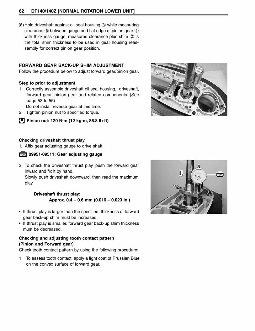
Step to prior to adjustment1. Correctly assemble driveshaft oil seal housing, driveshaft,
forward gear, pinion gear and related components. (Seepage 53 to 55)Do not install reverse gear at this time.
2. Tighten pinion nut to specified torque.
Pinion nut: 120 N.m (12 kg-m, 86.8 lb-ft)
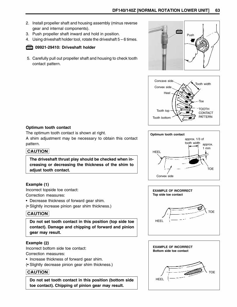
Checking driveshaft thrust play1. Affix gear adjusting gauge to drive shaft.
09951-09511: Gear adjusting gauge
2. To check the driveshaft thrust play, push the forward gearinward and fix it by hand.Slowly push driveshaft downward, then read the maximumplay.
Driveshaft thrust play:Approx. 0.4 – 0.6 mm (0.016 – 0.023 in.)
• If thrust play is larger than the specified, thickness of forwardgear back-up shim must be increased.
• If thrust play is smaller, forward gear back-up shim thicknessmust be decreased.
Checking and adjusting tooth contact pattern(Pinion and Forward gear)Check tooth contact pattern by using the following procedure:
1. To assess tooth contact, apply a light coat of Prussian Blueon the convex surface of forward gear.
DF140/140Z [NORMAL ROTATION LOWER UNIT] 63
2. Install propeller shaft and housing assembly (minus reversegear and internal components).
3. Push propeller shaft inward and hold in position.4. Using driveshaft holder tool, rotate the driveshaft 5 – 6 times.
09921-29410: Driveshaft holder
5. Carefully pull out propeller shaft and housing to check toothcontact pattern.
Push
Optimum tooth contactThe optimum tooth contact is shown at right.A shim adjustment may be necessary to obtain this contactpattern.
The driveshaft thrust play should be checked when in-creasing or decreasing the thickness of the shim toadjust tooth contact.
Concave side
Convex side
Heel
Tooth top
Tooth bottom
Tooth width
Toe
TOOTHCONTACTPATTERN
Optimum tooth contact
HEEL
Convex side
TOE
approx. 1/3 oftooth width approx.
1 mm
Example (1)Incorrect topside toe contact:Correction measures:• Decrease thickness of forward gear shim.(• Slightly increase pinion gear shim thickness.)
Do not set tooth contact in this position (top side toecontact). Damage and chipping of forward and piniongear may result.
Example (2)Incorrect bottom side toe contact:Correction measures:• Increase thickness of forward gear shim.(• Slightly decrease pinion gear shim thickness.)
Do not set tooth contact in this position (bottom sidetoe contact). Chipping of pinion gear may result.
EXAMPLE OF INCORRECTTop side toe contact
HEEL
TOE
EXAMPLE OF INCORRECTBottom side toe contact
HEEL
TOE

64 DF140/140Z [NORMAL ROTATION LOWER UNIT]
CHECKING DRIVESHAFT THRUST PLAYAfter obtaining optimum tooth contact, driveshaft thrust playshould be measured.1. Affix gear adjusting gauge to driveshaft.
09951-09511: Gear adjusting gauge
2. Slowly push driveshaft downward.Read the maximum play. Designate this amount of play as(A).
Driveshaft thrust play:Approx. 0.4 – 0.6 mm (0.016 – 0.023 in.)
NOTE:Driveshaft thrust play (A) must be known to adjust reverse gearshim.
RECHECKING DRIVESHAFT THRUST PLAY(Reverse gear back-up shim adjustment)1. After adjusting forward gear tooth contact pattern, correctly
assemble propeller shaft, housing assembly, reverse gearand related components (See page 55 to 56).
2. Screw sliding hammer assembly onto propeller shaft andstrike a few gentle outward taps.
09930-30161: Propeller shaft remover – BBBBB09930-30102: Sliding hammer – AAAAA
3. Affix gear adjusting gauge to driveshaft.
09951-09511: Gear adjusting gauge
4. Push shaft downward and read maximum play. Designatethis measurement as play (B).
5. Compare play (B) to play (A) (page 64).6. Reverse gear back-up shim adjustment is correct if (B) is
equal to (A).
• If (B) is less than (A), reduce reverse gear back-up shimthickness.
A
B

DF140/140Z [NORMAL ROTATION LOWER UNIT] 65
CHECKING PROPELLER SHAFT THRUST PLAYAfter adjusting all gear positions, measure the propeller shaftthrust play. If not within the following specification, a shim ad-justment is required.
Propeller shaft thrust play: 0.2 – 0.4 mm(0.008 – 0.016 in.)
NOTE:Maintain the forward gear thrust washer at standard thickness(9.0 mm) and adjust only the reverse gear thrust washer withshim.
Measurement step:1. Assemble gear adjusting gauge to the propeller shaft.
09951-09511: Gear adjusting gauge
2. Push propeller shaft inward.3. Hold shaft in and set dial gauge pointer to zero.4. Slowly pull shaft outward and read the maximum thrust play
on the dial.• If measurement is more than specification, increase
reverse gear thrust washer thickness.• If measurement is less than specification, reduce re-
verse gear thrust washer thickness.

66 DF140/140Z [COUNTER ROTATION LOWER UNIT]
3
2
1
1. Forward gear2. Reverse gear3. Shift rod and shifter yoke
COUNTER ROTATION LOWER UNIT (DF140Z model)
The counter rotation unit reverse gear is installed in the position where, in the normal rotation unit, the forwardgear is located.Likewise, the counter rotation unit forward gear takes the position of normal rotation unit reverse gear.This change of gear arrangement, however, does not affect the remote control lever operation because theshift rod and shifter yoke have been also modified to operate in the opposite direction.
PROPELLER SELECTION FOR COUNTERROTATIONFor counter-rotation model, newly designed stainless steel pro-pellers are available as follows.Suzuki highly recommend to use the genuine Suzuki counter-rotation propeller for the counter rotation model.In case of twin installation, always use on both engines, thesame size normal rotation and counter-rotation propellers.
Blade × Diam. (in.) × Pitch (in.)
3 × 14 × 18
3 × 14 × 20
3 × 14 × 22
3 × 14 × 24

DF140/140Z [COUNTER ROTATION LOWER UNIT] 67
REMOVAL AND INSTALLATIONRefer to the procedures in DF90/115 service manual.
Always disconnect the battery cable, before removinglower unit.
DISASSEMBLYPlace a drain pan under the oil drain plug.Remove oil drain plug 1 first then oil level plug 2 and allowgear oil to drain.Inspect oil for water, contaminates or metal.
Remove cotter pin 3 from propeller nut and remove propellernut 4.Remove washer 5, spacer 6, propeller 7 and stopper 8 fromthe propeller shaft.
To prevent injury from propeller blades, wear glovesand place a block of wood between the anti-cavitationplate and the propeller blade tips to lock the propellerin place.
Loosen the four (4) bolts 1, then remove the water pump case2.
68 DF140/140Z [COUNTER ROTATION LOWER UNIT]
Remove the impeller 3, impeller key 6, pump under plate 4and dowel pins 5.Keep the impeller key 6 for reuse and discard the plate gas-ket.
Remove three (3) bolts 1 and shift rod guide housing assem-bly 2.
Remove the two (2) bolts 1 securing the propeller shaft bear-ing housing to the gearcase.
Using special tools, draw out the propeller shaft bearing hous-ing.Remove the propeller shaft and bearing housing assembly.
09930-30102: A Sliding hammer09930-30161: B Propeller shaft remover
Hold the pinion nut securely, then fit special tool to the driveshaftand loosen the pinion nut.
09921-29410: Driveshaft holder
A
B

DF140/140Z [COUNTER ROTATION LOWER UNIT] 69
Lift out driveshaft assembly 4.Remove the driveshaft collar 5, washer 6, wave washer 7,washer (with tab) 8 and washer 9 from driveshaft.
Unscrew the four (4) bolts 1 securing driveshaft oil seal hous-ing 2, then remove oil seal housing and pinion shim 3.
Remove the pinion gear 1.Remove reverse gear 2 (with reverse gear retainer 3) andthrust bearing 4.
Remove the reverse gear 2 from reverse gear retainer 3.
Remove the bearing thrust washer 5 and back-up shim 6.

70 DF140/140Z [COUNTER ROTATION LOWER UNIT]
To disassemble propeller shaft components, refer to the follow-ing:(a) Remove horizontal slider A and spacer B.(b) Remove the spring C from the clutch dog shifter.
Disassembly of propeller shaft componentsSlide propeller shaft away from forward gear 1 and bearinghousing assembly 2.
Remove the forward gear 3, forward gear thrust bearing 4,forward gear thrust washer 5, forward gear back-up shim 6.
Remove the propeller shaft thrust washer 7, propeller shaftthrust bearing 8, bearing washer 9 and shim 0 from propel-ler shaft bearing housing.
Remove the reverse gear bearing housing 7 and dowel pin 8.

DF140/140Z [COUNTER ROTATION LOWER UNIT] 71
(c) Use special tool to push the dog pin D out of the clutch dogshifter.
09922-89810: Shift pin remover
(d) Remove the clutch dog shifter E and connector pin F frompropeller shaft.
Disassembly of shift rod components(a) Remove the circlip 1 and washer 2.(b) Slide the shift rod 3 out of the shift rod guide housing.
(c) Remove the detent ball 4 and spring 5.
(d) Remove the pin 6 and shifter yoke 7.

72 DF140/140Z [COUNTER ROTATION LOWER UNIT]
INSPECTION
NOTE:If any component is worn excessively, cracked, defective ordamaged in any way, it must be replaced.
NOTE:Thoroughly wash all metal components with cleaning solventand dry with compressed air.
Wear safety grasses when using compressed air.
PROPELLER• Inspect the propeller for bent, chipped or broken blades.
Replace or repair propeller if in damaged condition.
• Inspect propeller bush splines. Replace or repair propeller ifsplines are worn or damaged.
• Inspect propeller bush for deterioration or slipping.Replace if necessary.
GEARCASE• Inspect the gearcase. Replace if cracked or damaged.• Visually check the pinion bearing. Replace if pitted, noisy or
rough.
NOTE:If removal and replacement are required, see the DF90/115service manual/ “PINION BEARING” section on page 9-7.
REVERSE GEAR BEARING HOUSING / RETAINER• Inspect the reverse gear retainer and reverse gear bearing
housing.Replace if cracked or damaged.
• Visually check each bearings. Replace if pitted, noisy or rough.
DF140/140Z [COUNTER ROTATION LOWER UNIT] 73
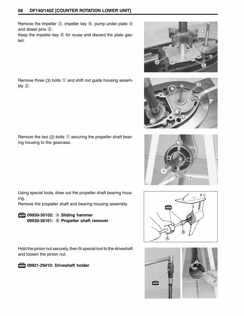
GEAR• Inspect forward, reverse and pinion gear teeth and engaging
dogs.Replace gears if damaged or worn.
• Inspect forward gear thrust bearing. Replace bearing if pit-ted, noisy or rough.
PROPELLER SHAFT COMPONENTS• Inspect horizontal slider and connector pin.
Replace if wear, damage or other abnormal condition.• Inspect clutch dog shifter. Replace if chipped, worn or dam-
aged.• Inspect dog pin. Replace if bent or worn.• Inspect propeller shaft/splines. Replace if worn, twisted or
damaged.• Inspect thrust bearing. Replace bearing if pitted, noisy or
rough.
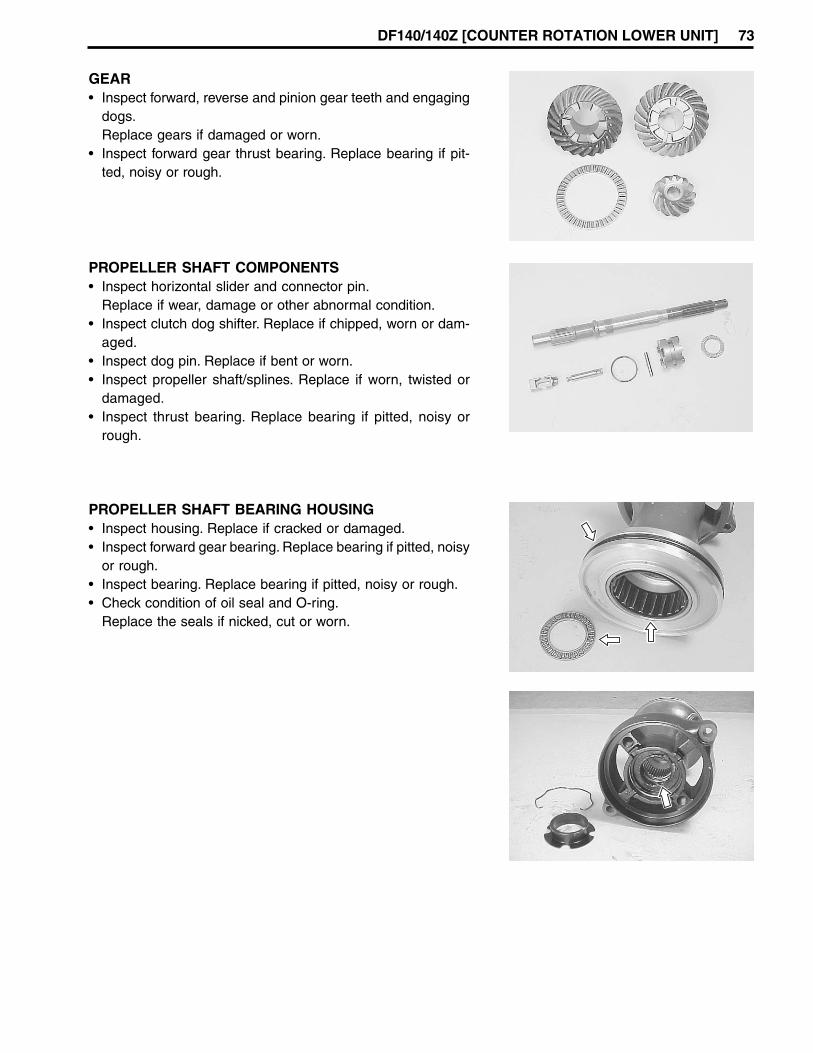
PROPELLER SHAFT BEARING HOUSING• Inspect housing. Replace if cracked or damaged.• Inspect forward gear bearing. Replace bearing if pitted, noisy
or rough.• Inspect bearing. Replace bearing if pitted, noisy or rough.• Check condition of oil seal and O-ring.
Replace the seals if nicked, cut or worn.

74 DF140/140Z [COUNTER ROTATION LOWER UNIT]
Replacing propeller shaft oil seal1. Remove the retaining ring 1 and washer 2.2. Extract the seals 3 with oil seal remover.
09913-50121: Oil seal remover
Do not reuse oil seal once removed.Always use new oil seal.
3. Apply Water Resistant Grease to the inner circumference ofthe housing.
WATER PUMP AND RELATED ITEMS• Inspect impeller. Replace if vanes are cut, torn or worn.• Inspect pump case. Replace if cracked, distorted or corroded.• Inspect under panel. Replace if cracked, distorted or corroded.
4. Using an oil seal installer, drive the two oil seals (one at atime) into the propeller shaft bearing housing.The lipped portion of the seal must face towards the propel-ler.Apply Water Resistant Grease to the seal lips.
99000-25160: Water Resistant Grease
5. Install washer and retaining ring.
SHIFT ROD GUIDE HOUSING COMPONENTS• Inspect shift rod guide housing. Replace if cracked or dam-
aged.• Inspect shifter yoke. Replace if wear, damage or other ab-
normal condition.• Inspect O-ring. Replace if nicked, cut, torn or swollen.• Inspect oil seal. Replace if nicked cut or worn.• Inspect shift rod/splines. Replace if worn, twisted or dam-
aged.• Inspect detent ball. Replace if wear, damage or other abnor-
mal condition.

DF140/140Z [COUNTER ROTATION LOWER UNIT] 75
DRIVESHAFTInspect driveshaft/splines. Replace if worn, twisted or damaged.Inspect driveshaft bearing, replace if pitted, noisy or rough.
DRIVESHAFT OIL SEAL HOUSING• Inspect housing. Replace if cracked or damaged.• Check condition of oil seals. Replace if nicked, cut or worn.• Inspect O-ring. Replace if worn, nicked or cut.
Replacing driveshaft oil seal1. With the oil seal remover, draw the two oil seals out of the
driveshaft oil seal housing.
09913-50121: Oil seal remover
2. Apply Water Resistant Grease to the inner circumferenceof the driveshaft oil seal housing.
99000-25160: Water Resistant Grease
3. Grease the inner lips of the seal.
With the lips facing away from driveshaft bearing, place sealin position and drive it into the oil seal housing. Direction of
water pump case

76 DF140/140Z [COUNTER ROTATION LOWER UNIT]
1 1 1 1 1 Oil seal2 2 2 2 2 Shift rod guide housing3 3 3 3 3 Bolt4 4 4 4 4 Ball5 5 5 5 5 Spring6 6 6 6 6 Notch plate7 7 7 7 7 O-ring8 8 8 8 8 Washer9 9 9 9 9 Circlip0 0 0 0 0 Seal coverA A A A A Shift rodB B B B B Yoke, shifterC C C C C PinD D D D D Horizontal sliderE E E E E MagnetoF F F F F GrommetG G G G G Water pump caseH H H H H PinI I I I I BoltJ J J J J KeyK K K K K Water pump impellerL L L L L Pump case under panelM M M M M GasketN N N N N Exhaust sealO O O O O Exhaust seal plateP P P P P UnionQ Q Q Q Q HoseR R R R R NippleS S S S S Gear caseT T T T T BoltU U U U U BoltV V V V V PinW W W W W AnodeX X X X X WasherY Y Y Y Y BoltZ Z Z Z Z Trim tab[ [ [ [ [ Bolt\ \ \ \ \ Screw] ] ] ] ] Water filter PORT^ ^ ^ ^ ^ Water filter STBD
ASSEMBLYAssembly is reverse of disassembly with special attention to following steps.
54 N.m (5.5 kg-m, 39.8 lb-ft)

DF140/140Z [COUNTER ROTATION LOWER UNIT] 77
13 N.m (1.3 kg-m, 9.5 lb-ft)
13 N.m(1.3 kg-m,9.5 lb-ft)
55 N.m (5.5 kg-m,40.0 lb-ft)
120 N.m(12 kg-m,86.8 lb-ft)
20 N.m(2.0 kg-m, 14.5 lb-ft)
aaaaa Driveshaftbbbbb Oil sealccccc Boltddddd Oil seal housingeeeee O-ringfffff Shimggggg Bearinghhhhh Washeriiiii Washerjjjjj Wave washerkkkkk Washerlllll Driveshaft collarmmmmm Plugnnnnn Gasketooooo Bearingppppp Dowel pin
qqqqq R-gear bearing housingrrrrr Bearingsssss Back-up shimttttt Thrust washeruuuuu Thrust bearingvvvvv R-gear retainerwwwww Bearingxxxxx Reverse gearyyyyy Pinion gearzzzzz Pinion nut Spacer||||| Connector pin Dog pin~~~~~ Clutch dog shifter;;;;; Dog spring::::: Propeller shaft,,,,, Forward gear..... F·gear thrust bearing
///// Thrust washer+++++ Back-up shim***** Thrust washer<<<<< Bearing>>>>> Washer????? Shim„„„„„ O-ring…………… Bearing††††† Propeller shaft bearing housing‡‡‡‡‡ Boltˆ Bearing‰‰‰‰‰ Oil sealŠŠŠŠŠ Washer‹‹‹‹‹ Retaining ringŒŒŒŒŒ Stopper””””” Propeller••••• Propeller bush––––– Spacer————— Washer˜ Nut™™™™™ Pin

78 DF140/140Z [COUNTER ROTATION LOWER UNIT]
• Make sure that all parts used in assembly are cleanand lubricated.
• After assembly, check parts for tightness andsmoothness of operation.
• Before final assembly, be absolutely certain that allgear contact, shim adjustments and tolerances arecorrect.Failure to correctly adjust these areas will result inlower unit damage.(See the “GEARS SHIMMING AND ADJUSTMENT”section on page 86.)
REVERSE GEAR BEARING HOUSING• Install dowel pin 1 and R-gear bearing housing 2 in posi-
tion.
PINION GEARPlace pinion gear in gearcase.
REVERSE GEAR• Place R-gear back-up shim 1 and bearing thrust washer 2
in position.
• Assemble the R-gear thrust bearing 3, reverse gear retainer4 and reverse gear 5, then install reverse gear/retainer as-sembly.
99000-22540: Suzuki Outboard Motor Gear Oil

DF140/140Z [COUNTER ROTATION LOWER UNIT] 79
DRIVESHAFT
DRIVESHAFT OIL SEAL HOUSINGApply Water Resistant Grease to the driveshaft oil seal.
99000-25160: Water Resistant Grease
Apply Water Resistant Grease to O-ring, then install the O-ringinto the groove on the driveshaft oil seal housing.
• Assemble the washer 1, washer (with the tab) 2, wavewasher 3, washer 4 and driveshaft collar 5 to the driveshaft.
• After installing driveshaft collar, fit the convex part of the col-lar in the concave part of the driveshaft by turning collar.
• Lower the driveshaft assembly 6 down into the gearcaseuntil the bottom of shaft protrudes through center of pinion.
NOTE:The washer tab must be located into groove on the gearcase.
• Install bearing outer race 7 and pinion shim 8 to driveshaft.
Install driveshaft oil seal housing on gearcase, then tighten four(4) bolts securely.

80 DF140/140Z [COUNTER ROTATION LOWER UNIT]
PINION NUTApply Thread Lock 1342 to the threads of the pinion nut beforethreading it onto the driveshaft.Tighten nut to the specified torque.
Pinion nut: 120 N.m (12 kg-m, 86.8 lb-ft)
99000-32050: Thread Lock 1342
09921-29410: Driveshaft holder
CHECKING DRIVESHAFT THRUST PLAYBefore installing forward gear, driveshaft thrust play shouldchecked.(See the “GEARS-SHIMMING AND ADJUSTMENT/CHECK-ING DRIVESHAFT THRUST PLAY” section on page 88.)
Driveshaft thrust play:Approx. 0.6 – 0.8 mm (0.024 – 0.031 in.)
09951-09511: Gear adjusting gauge
PROPELLER SHAFTSlide the clutch dog shifter 2 onto the propeller shaft 1.
NOTE:• For correct installation the side of the clutch dog shifter which
must face towards reverse gear is marked with the letter“R.E.V”.
Insert the connector pin 3 into propeller shaft.Align the holes in the shifter dog and connector pin and thenslide the dog pin 4 through both dog and connector pin.Install the dog pin retaining spring 5, ensuring that it fits snuglyinto the groove on the dog shifter.
R·E·V
Install the spacer 6 to propeller shaft.

DF140/140Z [COUNTER ROTATION LOWER UNIT] 81
FORWARD GEAR/PROPELLER SHAFT / BEARINGHOUSING• Assemble the propeller shaft in the following sequence:
99000-25160 : Water Resistant Grease
99000-22540 : Suzuki Outboard Motor Gear Oil
(a) Apply Water Resistant Grease to O-ring 1, then install theO-ring into the groove on the propeller shaft bearing hous-ing.
(b) Install shim 2, bearing washer 3, propeller shaft thrustbearing 4, propeller shaft thrust washer 5 into propellershaft bearing housing 6.
(c) Install F-gear back-up shim 7, F-gear thrust washer 8, F-gear thrust bearing 9 and forward gear 0 to propeller shaftbearing housing.
(d) Slide propeller shaft A into forward gear and propeller shaftbearing housing.
(e) Assemble horizontal slider B to connector pin.
To hold the correct bearing position, pull propeller shaft back-ward and then install propeller shaft and housing assembly inthe gearcase.
NOTE:To make the bearing housing fully seated in the gearcase, tapthe housing gently with plastic mallet.

82 DF140/140Z [COUNTER ROTATION LOWER UNIT]
When the housing is fully seated, tighten both retaining boltsto the specified torque.
Bearing housing bolt: 20 N.m (2.0 kg-m, 14.5 lb-ft)
RECHECKING DRIVESHAFT THRUST PLAYRecheck the driveshaft thrust play.
Driveshaft thrust play:Approx. 0.3 – 0.5 mm (0.012 – 0.020 in.)
09951-09511: Gear adjusting gauge
CHECKING PROPELLER SHAFT THRUST PLAYSee the “GEARS - SHIMMING AND ADJUSTMENT/CHECK-ING PROPELLER SHAFT THRUST PLAY” section on page 91.
SHIFT ROD GUIDE HOUSING• Install the spring 1 and detent ball 2 into shift rod guide
housing.• Apply Water Resistant Grease to the shift rod oil seal.
• Install shift rod 3 and washer 4 into the shift rod guidehousing 5, then secure it with the snap ring 6.
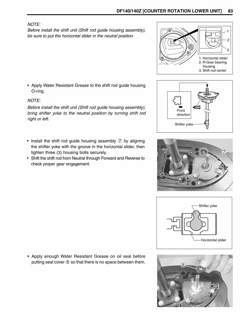
DF140/140Z [COUNTER ROTATION LOWER UNIT] 83
NOTE:Before install the shift unit (Shift rod guide housing assembly),be sure to put the horizontal slider in the neutral position.
• Apply Water Resistant Grease to the shift rod guide housingO-ring.
NOTE:
Before install the shift unit (Shift rod guide housing assembly),bring shifter yoke to the neutral position by turning shift rodright or left.
Frontdirection
Shifter yoke
Horizontal slider
Shifter yoke
• Install the shift rod guide housing assembly 7 by aligningthe shifter yoke with the groove in the horizontal slider, thentighten three (3) housing bolts securely.
• Shift the shift rod from Neutral through Forward and Reverse tocheck proper gear engagement.
• Apply enough Water Resistant Grease on oil seal beforeputting seal cover 8 so that there is no space between them.
1. Horizontal slider2. R-Gear bearing housing3. Shift rod center
2
3
1
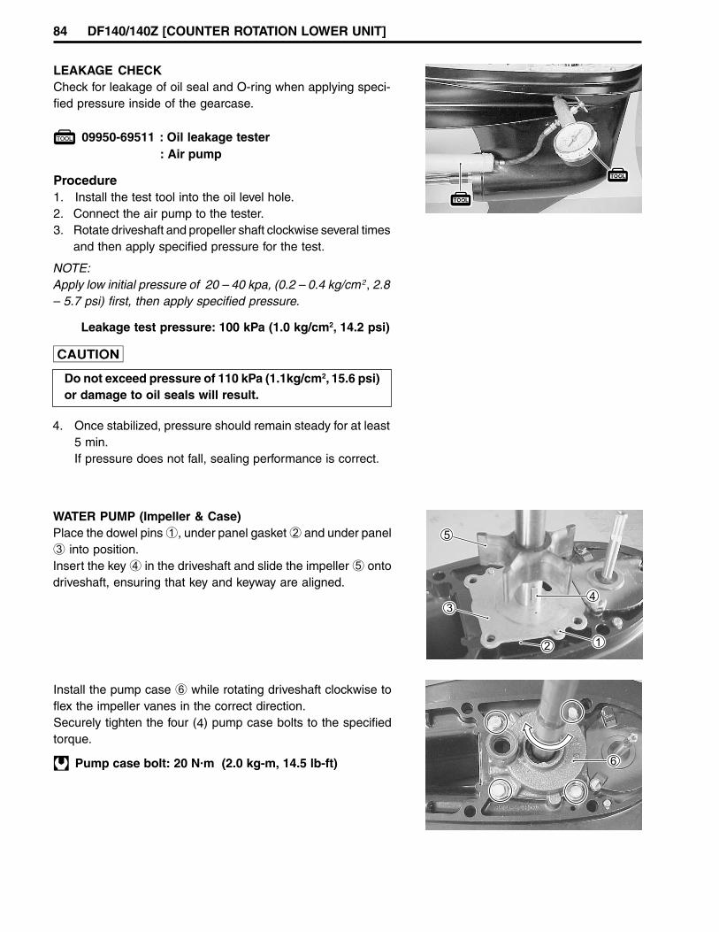
84 DF140/140Z [COUNTER ROTATION LOWER UNIT]
LEAKAGE CHECKCheck for leakage of oil seal and O-ring when applying speci-fied pressure inside of the gearcase.
09950-69511 : Oil leakage tester: Air pump
Leakage test pressure: 100 kPa (1.0 kg/cm2, 14.2 psi)
NOTE:Apply low initial pressure of 20 – 40 kpa, (0.2 – 0.4 kg/cm2, 2.8– 5.7 psi) first, then apply specified pressure.
Do not exceed pressure of 110 kPa (1.1kg/cm2, 15.6 psi)or damage to oil seals will result.
Procedure1. Install the test tool into the oil level hole.2. Connect the air pump to the tester.3. Rotate driveshaft and propeller shaft clockwise several times
and then apply specified pressure for the test.
4. Once stabilized, pressure should remain steady for at least5 min.If pressure does not fall, sealing performance is correct.
WATER PUMP (Impeller & Case)Place the dowel pins 1, under panel gasket 2 and under panel3 into position.Insert the key 4 in the driveshaft and slide the impeller 5 ontodriveshaft, ensuring that key and keyway are aligned.
Install the pump case 6 while rotating driveshaft clockwise toflex the impeller vanes in the correct direction.Securely tighten the four (4) pump case bolts to the specifiedtorque.
Pump case bolt: 20 N.m (2.0 kg-m, 14.5 lb-ft)

DF140/140Z [COUNTER ROTATION LOWER UNIT] 85
PROPELLER INSTALLATIONInstall propeller stopper 1 onto propeller shaft, then slide onthe propeller 2.Fit spacer 3, washer 4 and nut 5, then tighten nut to speci-fied torque.Push cotter pin 6 through nut and shaft, then bend to secure.
99000-25160: Water Resistant Grease
Propeller nut: 55 N.m (5.5 kg-m, 40.0 lb-ft)
GEAR OILFill the gearcase with specified gear oil for initial testing andrecheck the level after 10 minutes.Top up if necessary.
99000-22540: Suzuki Outboard Motor Gear Oil
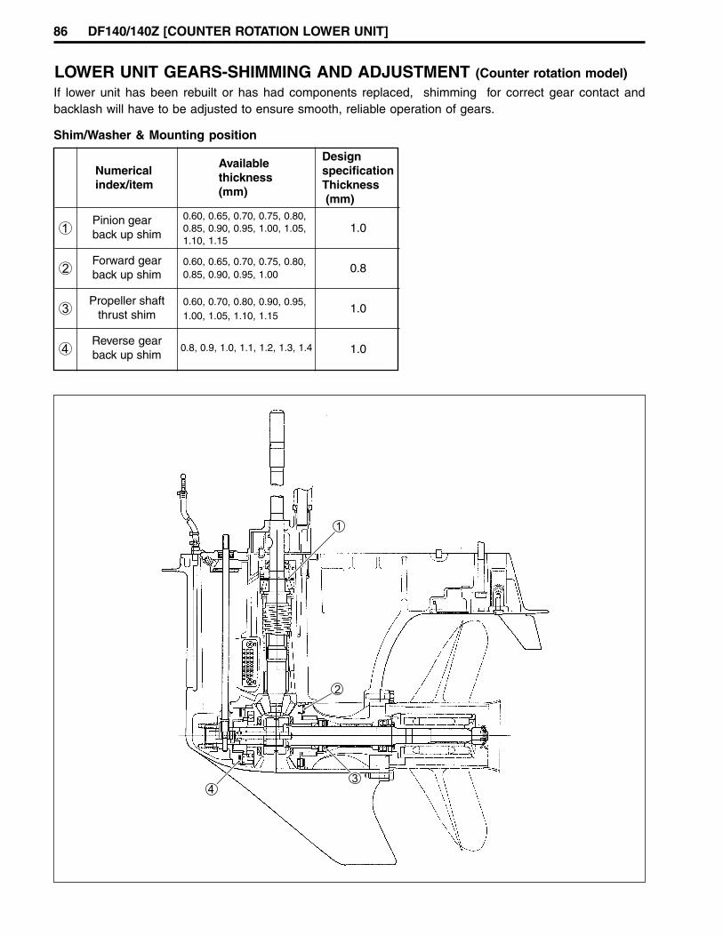
86 DF140/140Z [COUNTER ROTATION LOWER UNIT]
Reverse gearback up shim
LOWER UNIT GEARS-SHIMMING AND ADJUSTMENT (Counter rotation model)
1
Numericalindex/item
Availablethickness(mm)
DesignspecificationThickness (mm)
Pinion gearback up shim
0.60, 0.65, 0.70, 0.75, 0.80,0.85, 0.90, 0.95, 1.00, 1.05,1.10, 1.15
1.0
Forward gearback up shim 0.8
Propeller shaftthrust shim
0.60, 0.70, 0.80, 0.90, 0.95,1.00, 1.05, 1.10, 1.15
1.0
1.0
2
3
4
Shim/Washer & Mounting position
0.60, 0.65, 0.70, 0.75, 0.80,0.85, 0.90, 0.95, 1.00
0.8, 0.9, 1.0, 1.1, 1.2, 1.3, 1.4
If lower unit has been rebuilt or has had components replaced, shimming for correct gear contact andbacklash will have to be adjusted to ensure smooth, reliable operation of gears.

DF140/140Z [COUNTER ROTATION LOWER UNIT] 87
PINION GEAR BACK-UP SHIM ADJUSTMENT(1) Position the shimming gauge A horizontally in a vise and
tighten vise securely.
09951-09010: Shimming gauge
(2) Assemble the bearing outer race 1, back-up shim 2 anddriveshaft oil seal housing 3 to the driveshaft.
NOTE:Use a thinner pinion back-up shim 2 than the standard shimso that a clearance B exists.
(3) Insert the driveshaft through the shimming gauge A open-ing and then install pinion gear 4 and nut 5 to thedriveshaft, tighten pinion nut.
Pinion nut: 120 N.m (12 kg-m, 86.8 lb-ft)
(4) Install oil seal housing to shimming gauge with bolts 6.(5) Depress and hold driveshaft so that driveshaft bearing is
firmly seated in bearing outer race.(6) Hold driveshaft against oil seal housing 3 while measur-
ing clearance B between gauge and flat edge of piniongear 4 with thickness gauge, measured clearance plus shim2 is the total shim thickness to be used in gear housingreassembly for correct pinion gear position.

88 DF140/140Z [COUNTER ROTATION LOWER UNIT]
REVERSE GEAR BACK-UP SHIM ADJUSTMENT1. Correctly assemble reverse gear bearing housing, reverse
gear thrust bearing, reverse gear retainer, reverse gear, re-verse gear spacer, pinion gear, driveshaft assembly/oil sealhousing and related components.
2. Tighten pinion nut to specified torque.
Pinion nut: 120 N.m (12 kg-m, 86.8 lb-ft)
3. Install propeller shaft assembly and bearing housing as-sembly without the forward gear, then tighten bearing hous-ing retaining bolts to the specified torque.
4. Install the special tool to the bearing housing and then at-tach it to the propeller shaft as shown.
09951-98721: Gear holder
NOTE:• Before installing special tool, loosen the jam nuts securing
the long bolts and then remove the plate from long bolts.• Screw long bolts into the 10 mm thread on propeller shaft
bearing housing.
5. Turn the bolt 1 clockwise, and tighten until the propellershaft can rotate smoothly without play. Do not over tighten.
6. Affix gear adjusting gauge to driveshaft.
09951-09511: gear adjusting gauge
7. To check the driveshaft thrust play, slowly push driveshaftdownward, then read the maximum play.
Driveshaft thrust play:Approx. 0.6 – 0.8 mm (0.024 – 0.031 in.)
• If thrust play is larger than the specified , thickness of re-verse gear back-up shim must be increased.
• If thrust play is smaller, reverse gear back-up shim thick-ness must be decreased.
1. Jam nuts2. Plate
1
1
2

DF140/140Z [COUNTER ROTATION LOWER UNIT] 89
NOTE:• Before installing special tool, loosen the jam nuts securing
the long bolts and then remove the plate from long bolts.• Screw long bolts into the 10 mm thread on propeller shaft
bearing housing.
5. Install the special toll to gearcase and then attach it to thepropeller shaft as shown in the illustration.
09951-98721: Gear holder
6. Turn the bolt 1 counterclockwise and tighten until the pro-peller shaft can rotate smoothly without play.Do not over tighten.
Checking driveshaft thrust play(a) Affix gear adjusting gauge to driveshaft.
09951-09511: Gear adjusting gauge
(b) To check the driveshaft thrust play, slowly push driveshaftdownward, then read the maximum play
Driveshaft thrust play:Approx. 0.3 – 0.5 mm (0.012 – 0.020 in.)
• If thrust play is larger than the specified, thickness of forwardgear back-up shim must be increased.
• If thrust play is smaller, forward gear back-up shim thicknessmust be decreased.
FORWARD GEAR BACK-UP SHIM ADJUSTMENTFollow the procedure below to adjust forward gear.
Step to prior to adjustment1. Correctly assemble reverse gear, driveshaft oil seal hous-
ing, driveshaft, pinion gear and related components. (Seepage 78 – 80)
2. Tighten pinion nut to specified torque.
Pinion nut: 120 N.m (12 kg-m, 86.8 lb-ft)
3. Correctly assemble forward gear, forward gear bearing, pro-peller shaft, propeller shaft thrust bearing and propeller shaftbearing housing and related components, then install for-ward gear/propeller shaft/bearing housing assembly intogearcase.
4. Tighten both bearing housing retaining bolts to the speci-fied torque.
1. Jam nuts2. Plate
1
1
2

90 DF140/140Z [COUNTER ROTATION LOWER UNIT]
Checking and adjusting tooth contact pattern (Pinion and Forward gear)Check tooth contact pattern by using the following procedure:
(A) To assess tooth contact, apply a light coat of Prussian Blueon the convex surface of forward gear.
(B) In accordance with step 1 – 6, assemble the lower unit,then install the special tool.Turn the bolt 1 counterclockwise and tighten until the pro-peller shaft can rotate smoothly without play.Do not over tighten.
NOTE:While assessing tooth contact, place the clutch dog shifter toNeutral position.
09951-98721: Gear holder
(C) Using driveshaft holder tool, rotate the driveshaft 5 – 6 times.
09921-29410: Driveshaft holder
(D) Carefully pull out propeller shaft and housing to check toothcontact pattern.
Optimum tooth contactThe optimum tooth contact is shown at right.A shim adjustment may be necessary to obtain this contactpattern.
The driveshaft thrust play should be checked when in-creasing or decreasing the thickness of the shim toadjust tooth contact.
Concave side
Convex side
Heel
Tooth top
Tooth bottom
Tooth width
Toe
TOOTHCONTACTPATTERN
Optimum tooth contact
HEEL
Convex side
TOE
approx. 1/3 oftooth width approx.
1 mm
Example (1)Incorrect topside toe contact:Correction measures:• Decrease thickness of forward gear shim.(• Slightly increase pinion gear shim thickness.)
Do not set tooth contact in this position (top side toecontact). Damage and chipping of forward and piniongear may result.
EXAMPLE OF INCORRECTTop side toe contact
HEEL
TOE

DF140/140Z [COUNTER ROTATION LOWER UNIT] 91
CHECKING PROPELLER SHAFT THRUST PLAYAfter adjusting all gear positions, measure the propeller shaftthrust play. If not within the following specification, a shim ad-justment is required.
Propeller shaft thrust play: 0.2 – 0.4 mm(0.008 – 0.016 in.)
Measurement step:1. Assemble gear adjusting gauge to the propeller shaft.
09951-09511: Gear adjusting gauge
2. Push propeller shaft inward.3. Hold shaft in and set dial gauge pointer to zero.4. Slowly pull shaft outward and read the maximum thrust play
on the dial.• If measurement is more than specification, increase
propeller shaft thrust shim thickness.• If measurement is less than specification, reduce pro-
peller shaft thrust shim thickness.
Example (2)Incorrect bottom side toe contact:Correction measures:• Increase thickness of forward gear shim.(• Slightly decrease pinion gear shim thickness.)
Do not set tooth contact in this position (bottom sidetoe contact). Chipping of pinion gear may result.
EXAMPLE OF INCORRECTBottom side toe contact
HEEL
TOE

92 DF
140/140Z [W
IRIN
G D
IAG
RA
M]
WIR
ING
DIA
GR
AM
DF
140T/140Z
M
FP
M
+
+
–
BZ
PUSH TURN
BrO
GrWGB
PU
SH
FR
EE
STA
RT
IG OF
F
GNDSTOPBATT
IGSTARTBUZZERCANCEL
DN
DN
UP
UP
#1
#2
#3
#4
MONITORTACHO-METER
Bl-TUBE
W-TUBE
W-TUBE
Bl-TUBE
BBl/W
R/GBGrB
R/GB
R/GB
R/GB
R/GB
R/G B
R/G B
R/G
R/G
GrB
GrB
GrB
GrB
GrBY
GrBY
Bl/BG/YP
G/W
BPOGr
Gr B
GrB
W/YB
W/YB
B Lbl
WR
GrP
Gr Gr
Gr
W
PLblWYB
Gr
B
Gr
B
Gr
Gr
W
Gr
Bl Bl
Br
Br
Br
O
G
G G
W
W/YB
W/YB
P
Gr
Bl/B
P
P
Lbl
P
Lbl
W
Y
Gr
B
O
Br
Bl/R
GrB/R
B/WLg/B
Lg/R
Br
Y/G
W B/W
Br
Y/G
PP
Lb
lL
bl
R/B
B/W
W
W
W
RR
Bl
B B
B
B Y/G R R P/B Gr
W Gr
Y/W BB
B
Bl
G
R
RP Lb
l
P Lb
l
R
P Lb
l
P
W/R
Lb
l
B B B
W
W
W
W
Bl
Gr
Gr
Gr
Gr
B
Gr
Gr
R
B B
B B
B
O
O
Br
G
Bl
G/Y
G/W
W
Y/B
Gr
B
W/R
R/B
B/G
R
W W
BB/W
Bl
O
Y
B
CAUTION BUZZER (OVERHEAT / OIL PRESSURE/
BATTERY VOLTAGE / DIAGNOSIS)
BATTERY CHARGE COIL
HIGH PRESSUREFUEL PUMP
FUEL INJECTORS
CYLINDER TEMPSENSOR
CMP SENSOR
IGNITION COILS
EX-MANI TEMPSENSOR
RECTIFIER ®ULATOR
JOINT CONNECTOR
ENGINE CONTROL MODULE
STARTER MOTORRELAY
CKP SENSOR
ECM MAINRELAY
STARTER MOTOR
ALTERNATOR
FUSE 30A FUSE 60A
COMMUNICATIONCONNECTOR
PTT SWITCH
PTT MOTOR
BATTERY 12V 100AH
TRIM SENDER
IAT SENSOR
IAC VALVE
MAPSENSOR
METER ILLUMINATIONSWITCH
METER
TRIMMETER
PTT SWITCH
PTT SWITCH
REMOTE CONTROL BOX
IGNITION SWITCH
EMERGENCY STOP SWITCHLock plate IN RUNLock plate OFF STOP
PTT MOTOR RELAY UP
PTT MOTOR RELAY DN
NEUTRAL SWITCHN ONF,R OFF
WIRE COLORBBrBlGGrLblLgOPRWYB/GB/WB/Y
: Black: Brown: Blue: Green: Gray: Light blue: Light green: Orange: Pink: Red: White: Yellow: Black with Green tracer: Black with White tracer: Black with Yellow tracer
G/YG/WLg/BLg/WLg/YO/BO/GP/BR/BR/GR/WW/YW/RY/GY/W
: Green with Yellow tracer: Green with White tracer: Light green with Black tracer: Light green with White tracer: Light green with Yellow tracer: Orange with Black tracer: Orange with Green tracer: Pink with Black tracer: Red with Green tracer: Red with Blue tracer: Red with White tracer: White with Yellow tracer: White with Red tracer: Yellow with Green tracer: Yellow with White tracer
CTP SWITCH
DN UP
CAP
#1
#2
#3
#4
OIL PRESSURE SWITCH1.0kgf/cm2 or less ON
PLblWYB
Gr
RBGrYB
Gr
R/GBGrB
R/GB
R/GB
R/GB
R/GB
R/G B
R/G B
R/G
R/G
GrB
GrB
GrB
GrB
GrBY
GrBY
Gr B
GrB
B
WR
GrW
Bl/BG/YP
G/W
Lbl
GrP
Gr
Gr
B
Gr
B
Gr
Gr
W
Gr
Bl Bl
Br BrO
G
G G
W
PP
Lb
lL
bl
BPOGr
W/YB
W/YB
W/YB
PGrP
Lbl
WYGrB
BO
OBrGBl
W/YB
Bl/BP
PLbl
OBr
Bl/R
GrB/R
B/WLg/B
Lg/R
BrY/G
W B/W
Br
Y/G
Y O/YY O/Y
R/B
B/W
W
B
B
Bl
G
R
RP Lb
lP Lb
l
R
P Lb
l
P
W/R
Lb
l
W Br B/W Gr
V/W P/B
O/Y Y R
Lg
/BB
l/B P O Y/B
Bl/W Br
B/W
Lg
/W B BB
/W B/Y Lg Bl
R/B Gr
B/G Bl
WL
g/R
G/Y
G/W
Bl/R B/R
O/G B B O/B
R/W O
G/YG/W
Gr
B/G B
WY/BGr
B
W/R
R/B
B/G
R
Gr
B/G B
Bl/WB
W
W
RRR
Bl
BB B
B
B
B Y/G R R P/B Gr
W Gr
V/W B
B BB B
B
WW
WW
W W
BB/W
B
Gr
GrBl
O
V
Gr
Gr
Gr
Gr
BlB
Br
GrGrB/WB/W
GrB/W
Lg/WLg/W
B/WB/WGrGr
B/WB/W
O/GO/G
Lg/WB/W
B/WGr
O/G
O/BO/B
B/YB/Y
R/WR/W
LgLg
O/B
B/Y
R/W
Lg
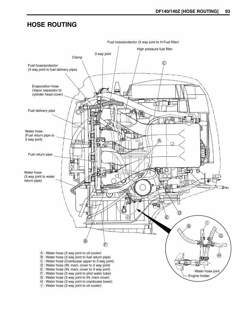
DF140/140Z [HOSE ROUTING] 93
HOSE ROUTING
High pressure fuel filter
Fuel hose/protector (3 way joint to H·Fuel filter)
3 way jointClamp
Fuel hose/protector(3 way joint to fuel delivery pipe)
Evaporation hose(Vapor separator tocylinder head cover)
Fuel delivery pipe
Water hose(Fuel return pipe to3 way joint)
Water hose(3 way joint to waterreturn pipe)
A : Water hose (3 way joint to oil cooler)B : Water hose (3 way joint to fuel return pipe)C : Water hose (Crankcase upper to 3 way joint)D : Water hose (IN. mani. cover to 3 way joint)E : Water hose (IN. mani. cover to 3 way joint)F : Water hose (3 way joint to pilot water tube)G : Water hose (3 way joint to IN. mani cover)H : Water hose (3 way joint to crankcase lower)I : Water hose (3 way joint to oil cooler)
Fuel return pipe
Water hose jointEngine holder

Prepared by
Marine & Power Products Division
November, 2001
Manual No. 99501-92J00-01E
Printed in Japan
96
Printed in Japan TK
K2