supplementary information for multifunctional protective
TRANSCRIPT
1
Supplementary Information for
2D Material-Integrated Hydrogels as
Multifunctional Protective Skins for Soft Robots
Lin Jing,1 Li-Yin Hsiao,1 Shuo Li,1 Haitao Yang,1 Patricia Li Ping Ng,1 Meng Ding,1 Tien
Van Truong,2 Si-Ping Gao,3 Kerui Li,1 Yong-Xin Guo,3 Pablo Valdivia y Alvarado,2 Po-
Yen Chen1*
1. Department of Chemical and Biomolecular Engineering, National University of
Singapore, 4 Engineering Drive 4, Singapore 117585.
2. Engineering Product Development, Singapore University of Technology and Design, 8
Somapah Road, Singapore 487372.
3. Department of Electrical and Computer Engineering, National University of Singapore,
4 Engineering Drive 3, Singapore 117583.
*Corresponding author. E-mail address: [email protected]
Electronic Supplementary Material (ESI) for Materials Horizons.This journal is © The Royal Society of Chemistry 2021

2
This supplementary file includes:
Experimental Section
Figures S1 to S35
Notes S1 to S4
Supplementary References
Other Supplementary Information for this manuscript include the following:
Videos S1 to S7

3
Experimental Section 5-9Fig. S1 Hydrophilic surface modification of soft elastomeric
bodies by polydopamine (PDA) grafting.10
Fig. S2 Crosslinking processes of gelatin hydrogel and MXene-blended hydrogel (M-H).
11
Fig. S3 Scalable deposition techniques for conformal hydrogel layer.
12
Fig. S4 TEM images of 2DM nanosheets. 12Fig. S5 Characterization of Mg2+-intercalated 2DM nanolayers. 13Fig. S6 Elemental characterization of 2DM/H robotic skins. 13Fig. S7 Mechanical delamination test results of MXene/hydrogel
and MMT/hydrogel interfaces.14
Fig. S8 Detailed fabrication processes of all 2DM/H soft grippers.
14
Fig. S9 Determination of characteristic wavelength of isotropic crumples under increasing areal strains.
15
Fig. S10 Fatigue tests on 2DM/H robotic skins. 15Fig. S11 Control experiments for installation of 2DM/H robotic
skins.16
Fig. S12 Effects of hydrogel thickness on the performance of hydrogel-elastomer bilayer structures.
17
Fig. S13 XRD analyses of as-filtered GO, MMT, and MXene membranes.
18
Fig. S14 XRD analyses of GO, MMT, and MXene membranes transferred onto hydrogels.
18
Fig. S15 Coordinated grasping missions in water. 19Fig. S16 Grasping behaviors of various soft grippers upon DCM
and THF exposure.19
Fig. S17 Solvent contact assay for stretchable GO/H robotic skin. 20Fig. S18 High-resolution characterization of barrier performance. 21Fig. S19 Zoomed-in photos of the GO/H gripper before and after
working in DCM for long time.22
Fig. S20 Heat regulation performances of gelatin hydrogel, MMT/H, and GO/H robotic skins
22
Fig. S21 Effects of hydrogel hydration degree on the heat regulation and fire retardancy of MMT/H layer.
23
Fig. S22 I–V curves of MXene/H skins. 23Fig. S23 Biofilm assay quantifications. 24Fig. S24 Effect of hydration degree on the sensing performance of
M-H layer.24

4
Fig. S25 Fabrication process of a GO/M-H gripper with high-level function integration.
25
Fig. S26 Configuration of GO/M-H robotic skin. 25Fig. S27 Tensile tests of elastomeric body and hydrogel layer. 26Fig. S28 Time-variant displacements information of bare and
GO/M-H protected grippers.26
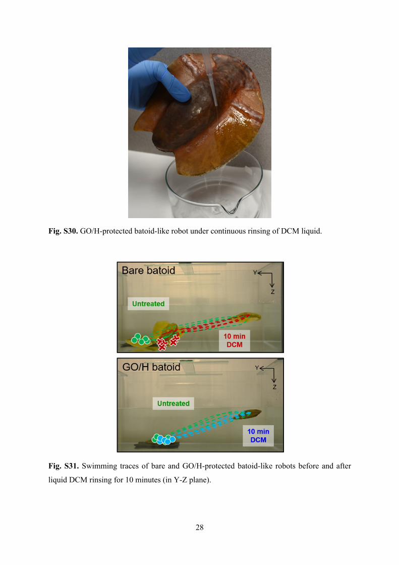
Fig. S29 Assembly of a dual-bellows walker robot. 27Fig. S30 GO/H-protected batoid-like robot under continuous
rinsing of DCM liquid.28
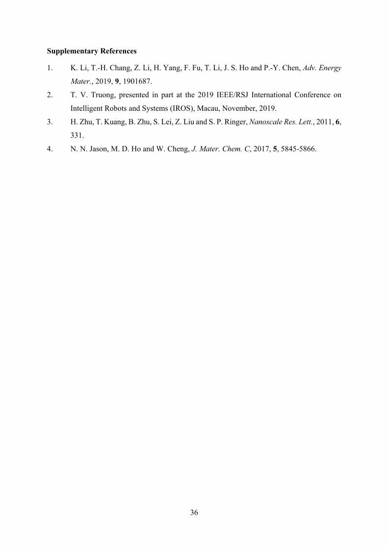
Fig. S31 Swimming traces of bare and GO/H-protected batoid-like robots before and after liquid DCM rinsing for 10 minutes (in Y-Z plane).
28
Fig. S32 Reaction details of gelatin crosslinking. 29Fig. S33 Mechanical delamination tests. 30Fig. S34 Diffusion cell setup for characterization of DCM
permeation across GO/H skins.31
Fig. S35 Setup of EMI shielding measurement. 34
Note S1 Reaction details of gelatin crosslinking. 29Note S2 Delamination test details. 30Note S3 Organic solvent diffusion tests. 31Note S4 Characterization of EMI SE. 33
Video S1 GO/H Robot for Soft Grasping Missions within Organic Liquids (Dichloromethane)
Video S2 MMT/H Robot for Soft Grasping Missions in Open FireVideo S3 GO/M-H Robot for Soft Grasping Missions within
Organic LiquidsVideo S4 GO/M-H Robot for Soft Grasping Missions within Hot
Organic LiquidsVideo S5 MMT/H Origami Robot for Vision Guided Search
Mission within Open FireVideo S6 Underwater Locomotion Behaviors of Bare & GO/H
Batoid Robots Upon DCM ExposureVideo S7 Autonomous Underwater Locomotion of GO/H Batoid
Robot Upon DCM Spills
Supplementary References 35
5
Experimental Section
Materials.
Lithium fluoride (LiF, Sigma-Aldrich, BioUltra, ≥99.0%), hydrochloric acid (HCl, Sigma-
Aldrich, ACS reagent, 37%), Ti3AlC2 MAX powders (Tongrun Info Technology Co. Ltd,
China), sodium montmorillonite (MMT, BYK Additives Incorporation; Cloisite Na+),
graphene oxide (GO) aqueous dispersion (Angstron Materials Incorporation, 5 mg mL−1), and
dichloromethane (DCM, J.T. Baker, 99.9%) were used as received without further purification.
Magnesium chloride hexahydrate (MgCl2∙6H2O), dimethyl sulfoxide (DMSO),
tetrahydrofuran (THF), chloroform, hexane, gelatin (from cold water fish skin), glutaraldehyde
solution (25% in H2O), dopamine hydrochloride, and tris(hydroxymethyl)aminomethane were
purchased from Sigma-Aldrich and used as received. The silicone elastomers (EcoflexTM-0020,
EcoflexTM-0030, EcoflexTM-0035) were purchased from Smooth-On. Polydimethylsiloxane
(PDMS, SYLGARD™ 184 Silicone Elastomer Kit) was purchased from Dow Inc. Latex
actuators (Aihua Balloons, Hebei, P. R. China) were used after cleaning with ethanol.
Deionized (DI) water (18.2 MΩ) was obtained from a Milli-Q water purification system
(Millipore Corp., Bedford, MA, USA) and used as the water source throughout the work.
Preparation of Ti3C2Tx MXene nanosheets.
Ti3C2Tx MXene nanosheets were prepared according to our previous work.1 1.0 g of LiF was
added to 6.0 M HCl solution (20 mL) under vigorous stirring. After the dissolution of LiF, 1.0
g of Ti3AlC2 MAX powder was slowly added into the HF-containing solution. The mixture
was kept at 35 °C for 24 hours. Afterwards, the solid residue was washed with deionized (DI)
water several times until the pH value increased to ca. 7.0. Subsequently, the washed residue
was added into 100 mL of deionized water, ultrasonicated for 1 hour under N2 atmosphere, and
centrifuged at 3,000 r.p.m. for 30 minutes. The supernatant was collected as the final
suspension of Ti3C2Tx MXene nanosheets with the concentration of ca. 5 mg mL–1.
Preparation of MMT nanosheets.
MMT nanosheet dispersion was synthesized by mixing as-received MMT powders in DI water
(10 mg mL−1), followed by the ultrasonication (Sonica 5200) for 2 hours and continuous
stirring for 12 hours. The dispersion was then centrifuged at 4,000 rpm for 60 minutes, and the

6
supernatant was collected. The concentration of obtained MMT dispersion is about 7 mg mL−1
(solid weight was measured after solvent evaporation at 90 °C), which was diluted to 5 mg
mL−1 for further usage.
Fabrication of soft pneumatic grippers.
The molds of soft pneumatic gripper were designed using a computer-aided design software
(Alibre, Inc.) and created by a 3D printer with acrylonitrile butadiene styrene plastic. An air
channel was designed on the mold, and the robot’s body was formed by curing silicone
elastomers in the 3D printed molds. Two silicone elastomers were used: a highly extensible,
elastomeric one (EcoflexTM-0020) and a relatively inextensible, compliant one (PDMS). The
mold (with the design of air channel) was first filled with EcoflexTM-0020, and the elastomer
was allowed to cure for 5 hours at room temperature. Then, the cured robotic body was peeled
off from the mold and sealed with a flat PDMS layer with the adhesion of EcoflexTM-0035.
Preparation of gelatin hydrogel and MXene-blended hydrogel (M-H) layers.
Generally, the precursor solution of hydrogel layer consisted of gelatin (12.0 wt.%),
glutaraldehyde (0.40 wt.%), MgCl2 (7.6 wt.%, i.e., 1.0 M), and DI water. Gelatin and MgCl2
powders were first dissolved into DI water and stirred overnight. After the introduction of
glutaraldehyde, the hydrogel precursor solution started to crosslink and finally became a
freestanding gelatin hydrogel after 6 minutes.
On the other hand, the precursor solution of MXene-blended gelatin hydrogel (M-H)
was composed of gelatin (12.0 wt.%), glutaraldehyde (0.40 wt.%), MgCl2 (7.6 wt.%, i.e., 1.0
M), MXene nanosheets at various loadings (0.25, 0.50 and 0.75 wt.%), and DI water. Gelatin
powders were first dissolved into the MXene dispersion and stirred overnight. Then, the
solution of glutaraldehyde and MgCl2 was added into the MXene-gelatin mixture, and the
conductive M-H layer was obtained after in situ crosslinking for 7 minutes.
Characterization of temperature regulation performance.
We first prepared bare elastomer, gelatin hydrogel, GO/H, MMT/H, and MXene/H samples
with identical dimensions. These samples were then put in an oven at 50 °C for 60 minutes,
and their mass changes were monitored every 5 minutes. We further examined their

7
temperature regulation performance on a hotplate at 200 °C for 10 minutes, and their surface
temperature was monitored every 30 seconds using a thermocouple. The temperature
regulation performance at different stretching stages was examined by stretching the 2DM/H
skins under certain uniaxial strains (50% and 100%) and then fixing them onto a 100 °C
hotplate for 10 minutes. Their surface temperatures were monitored every 30 seconds using a
thermocouple.
Fabrication of soft pneumatic grippers coated with 2DM/H and GO/M-H skins.
First, the soft pneumatic gripper was actuated to its full inflation volume and then immersed in
the dilute solution of dopamine (5 mg mL–1) and tris(hydroxymethyl)aminomethane (10 mM)
at pH 8.5 for 24 hours. Afterwards, the surface of elastomeric body was grafted with
polydopamine (PDA) (with thickness of ca. 50 nm). Then, the soft gripper was taken out and
rinsed with DI water followed by coating with the precursor solution of hydrogel layer or M-
H layer. The thickness of hydrogel (and M-H) layer was controlled to be ca. 100 µm through
brush coating, dip coating, or drop casting. The hydrogel-coated or (M-H-coated) soft gripper
was then dipped into GO, MMT, or MXene dispersion, and the thickness of 2DM nanolayer
was controlled by adjusting the concentration of 2DM dispersion and the coating time. For this
work, we fixed the concentrations of GO, MMT, and MXene dispersions at 5.0 mg mL–1,
respectively, and the dip coating time was fixed at 1 minute to achieve the GO, MMT, and
MXene nanolayers with thicknesses of ca. 4, 5, and 6 μm, respectively. The above fabrication
recipes were utilized throughout the soft robots demonstrated in this work.
Fabrication of a dual-bellows walker robot coated with MMT/H skin.
In brief, two bellows origami were first assembled using cellulose papers, and these cellulose
origami were enclosed with glue and further stabilized with a thin layer of PDMS. Afterwards,
plastic covers and pneumatic channels were connected to two bellows tubes to complete the
fabrication of a dual-bellows walker robot. The connection points between pneumatic channels
and walker robot were further sealed with PDMS to ensure no air leaks. Two friction feet were
then 3D printed and installed at the head and tail of dual-bellows walker robot, allowing the
robot to crawl as commanded.
The dual-bellows walker robot was then grafted with PDA to achieve sufficient surface
hydrophilicity. Then, the hydrogel layer (with thickness of ca. 100 μm) was deposited onto the

8
robot through brush coating. Afterwards, upon dipping the hydrogel coated robot into the
dispersion of MMT nanosheets (5 mg mL–1) for 1 minute, the MMT nanolayer (with thickness
of 5 µm) was conformally coated onto the dual-bellows walker robot.
Fabrication of a soft batoid-like robot coated with GO/H skin.
Soft batoid-like robot was fabricated according to our previous work2 with the fabrication
details regarding electronic circuit design provided. To integrate GO/H robotic skin, the soft
batoid-like robot was grafted with PDA to achieve sufficient surface hydrophilicity. Then, the
hydrogel layer (with thickness of ca. 100 μm) was deposited onto the robot through brush
coating. Afterwards, upon dipping the hydrogel coated robot into the dispersion of GO
nanosheets (3 mg mL–1) for 1 minute, the GO nanolayer (with thickness of 3 µm) was
conformally coated onto the soft batoid-like robot.
Biofilm formation tests.
Both bacteria, S. aureus and E. coli, were cultured in LB medium overnight at 37 °C, and the
bacterial solutions were then diluted at the ratio of 1:100. Afterwards, the samples of gelatin
hydrogel and MXene/H skin (with diameter of 15.6 mm and height of 0.6 mm) were placed in
a 24-well plate, and 1 mL of bacterial solution was added into each well followed by the
incubation at 37 °C without shaking for 20 hours. Afterwards, the samples were rinsed with DI
water for three times to remove unattached bacterial cells. Next, 1 mL of 0.1% crystal violet
aqueous solution was added into each well followed by the incubation at room temperature for
15 minutes, after which the samples were rinsed with DI water for three times. 1 mL of 30%
acetic acid was then added into each well to solubilize the crystal violet followed by the
incubation at room temperature for 15 minutes. The optical density (OD) of crystal violet
solution was then measured at 550 nm to quantify the degrees of biofilm formation. The
statistical analyses were conducted in triplicate, and the data were reported as mean ± standard
deviation (SD).
Uniaxial tensile tests.
The samples of elastomer (EcoflexTM-0020), hydrogel-coated elastomer, 2DM/H-protected
elastomer, freestanding gelatin hydrogel and M-H layers (0.5 wt.% Maxine loading) were

9
prepared with the identical dimensions of 5 (L) × 2 (W) × 0.25 (T) cm3. These samples were
tested by a tensile tester (Instron 5543, Instron, USA) equipped with a 500 N load cell. The
stress–strain properties were acquired at a strain rate of 25% s–1 until fracture or till 500%
strain, and all the tests were repeated at least three times.
Fire retardancy tests.
Fire retardancies of bare soft gripper, hydrogel-coated soft gripper, MMT/H-protected soft
gripper, bare elastomer strips, hydrogel-coated elastomer strips, and MMT/H-protected
elastomer strips were evaluated by the horizontal combustibility test method modified from the
standard test method (ASMT D6413).3 Fire retardancy was evaluated by exposing the samples
to the flame of an ethanol burner for 60 seconds (the flame temperature is reported to be 600–
850 °C).4 The test processes and results were recorded via a digital camera.
Characterization.
Surface morphologies and cross-section information of 2DM/H skins were obtained by using
a scanning electron microscope (SEM, FEI Quanta 600), a benchtop SEM (JCM-7000
NeoScopeTM Benchtop), and a field emission SEM (JEOL-JSM-6610LV) operated at 15.0 kV.
As-exfoliated MXene, MMT, and as-received GO nanosheets were characterized by using a
high-resolution transmission electron microscopy (HRTEM, JEOL 2010F). X-ray diffraction
(XRD) patterns were recorded by an X-ray diffractometer (Bruker, D8 Advance X-ray Powder
Diffractometer, Cu Kα (λ = 0.154 nm) radiation) with a scan rate of 2° min−1. Uniaxial tensile
tests and delamination tests were conducted by using a Universal Testing System (Instron 5543,
Instron, Canton, MA) at room temperature with a 500 N load cell. X-ray photoelectron
spectroscopy (XPS) was measured by Kratos AXIS UltraDLD by using a microfocused (100
µm, 25 W) Al X-ray beam with a photoelectron take off angle of 90°. DCM concentrations
within DCM/acetone mixtures were analyzed using gas chromatograph (Agilent 5977B
GC/MSD system). I–V profiles and electrical resistances of MXene/H skins and M-L layers
were measured using an electrochemical workstation, (AutoLab, Metrohm Singapore Pte.
Ltd.). EMI shielding performance of stretchable MXene/H skin in the X-band (8.2–12.0 GHz)
was characterized by using Agilent/HP 8510C Vector Network Analyzer. Optical density at
600 nm (OD600) of bacterial cells and fluorescence intensity of dyes as well as OD550 of crystal
violet were measured by a microplate reader (Biotek H4FM).
10
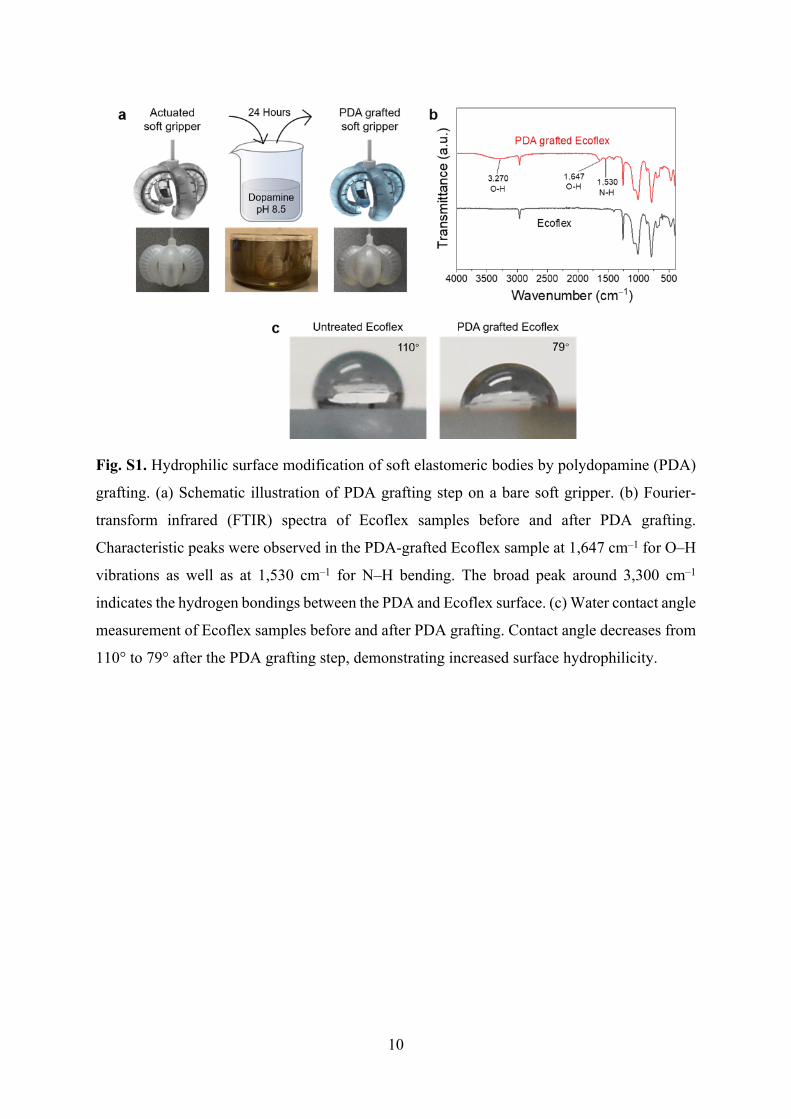
Fig. S1. Hydrophilic surface modification of soft elastomeric bodies by polydopamine (PDA)
grafting. (a) Schematic illustration of PDA grafting step on a bare soft gripper. (b) Fourier-
transform infrared (FTIR) spectra of Ecoflex samples before and after PDA grafting.
Characteristic peaks were observed in the PDA-grafted Ecoflex sample at 1,647 cm–1 for O–H
vibrations as well as at 1,530 cm–1 for N–H bending. The broad peak around 3,300 cm–1
indicates the hydrogen bondings between the PDA and Ecoflex surface. (c) Water contact angle
measurement of Ecoflex samples before and after PDA grafting. Contact angle decreases from
110° to 79° after the PDA grafting step, demonstrating increased surface hydrophilicity.
11
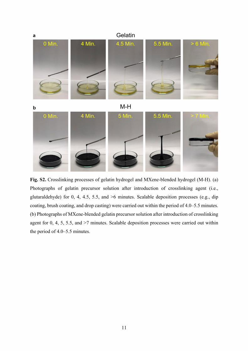
Fig. S2. Crosslinking processes of gelatin hydrogel and MXene-blended hydrogel (M-H). (a)
Photographs of gelatin precursor solution after introduction of crosslinking agent (i.e.,
glutaraldehyde) for 0, 4, 4.5, 5.5, and >6 minutes. Scalable deposition processes (e.g., dip
coating, brush coating, and drop casting) were carried out within the period of 4.0–5.5 minutes.
(b) Photographs of MXene-blended gelatin precursor solution after introduction of crosslinking
agent for 0, 4, 5, 5.5, and >7 minutes. Scalable deposition processes were carried out within
the period of 4.0–5.5 minutes.

12
Fig. S3. Scalable deposition techniques for conformal hydrogel layer. (a) Dip coating and (b)
drop casting were both applicable to deposit viscous gelatin paste onto a PDA grafted soft
gripper (under inflation).
Fig. S4. TEM images of 2DM nanosheets. Representative TEM images of (a) GO, (b) MXene,
and (c) MMT nanosheets used in this work.

13
Fig. S5. Characterization of Mg2+-intercalated 2DM nanolayers. (a) XPS spectra of GO/H and
MXene/H skins through cation (Mg2+) induced self-assembly. (b) For the cases of 1-minute
dip coating in 5 mg mL–1 of 2DM dispersions, 6.05 at.% and 5.01 at.% of Mg2+ were
characterized in the self-assembled GO and MMT nanolayers. It is worth noting that the at.%
of Mg2+ in MMT nanolayers was not able to be estimated, as MMT nanosheets contained
octahedral cations (Al, Mg, Fe).
Fig. S6. Elemental characterization of 2DM/H robotic skins. SEM images, EDX mapping, and
sum spectra of (a) gelatin, (b) GO/H, (c) MMT/H, and (d) MXene/H skins. Characteristic
elements of C, S, and Ti were observed in GO/H, MMT/H, and MXene/H skins, respectively.
Element of Mg was observed in all the samples, proving the successful Mg2+ intercalation into
2DM nanolayers. Scale bar: 20 μm.

14
Fig. S7. Mechanical delamination test results of MXene/hydrogel and MMT/hydrogel
interfaces.
Fig. S8. Detailed fabrication processes of all 2DM/H soft grippers. Brush coating was used for
deposition of MXene nanolayer onto a gelatin-coated gripper.

15
Fig. S9. Determination of characteristic wavelength of isotropic crumples under increasing
areal strains. The characteristic wavelength was defined as the size of an individual crumple.
With the areal strains increasing from 0% to 600% and 1,200%, the crumple sizes were
extracted and varied from ~15 × 15, 56 × 56, to 77 × 77 µm, respectively, demonstrating the
unfolding process of isotropic crumples. Scale bar: 50 µm.
Fig. S10. Fatigue tests on 2DM/H robotic skins. SEM images of GO/H, MXene/H, and MMT/H
robotic skins before and after 500 cycles of pneumatic actuations. No topographical changes
or emerging fractures/cracks were observed at their relaxed states, demonstrating the structural
stability of all 2DM/H skins. Scale bar: 50 µm.

16
Fig. S11. Control experiments for installation of 2DM/H robotic skins. Control experiments
showed that it is necessary to conduct two-step interfacial engineering process to achieve
conformal 2DM/H skin on a bare soft gripper. (a) Without PDA grafting and intermediate
hydrogel layer, 2DM nanolayer was not able to be deposited onto a bare gripper. (b) Without
PDA grafting, conformal gelatin layer was not able to be coated onto a bare gripper. (c) Without
intermediate hydrogel layer, 2DM nanolayer was not able to be deposited onto a PDA-grafted
gripper. (d) Without MgCl2, 2DM nanolayer was not able to be deposited onto a hydrogel-
coated gripper.

17
Fig. S12. (a–d) Photos of three hydrogel-elastomer bilayers with the hydrogel thicknesses of
50, 100, and 200 µm upon bending. Detachment of 200-μm-thick hydrogel layer from the
elastomer substrate was observed. (e) Heat regulation performance of three hydrogel-elastomer
bilayers with the hydrogel thicknesses of 50, 100, and 200 µm on a hotplate at 100 °C.
18
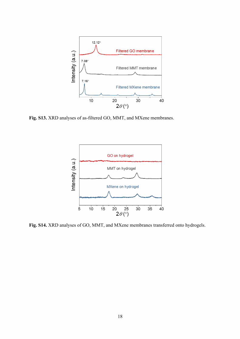
Fig. S13. XRD analyses of as-filtered GO, MMT, and MXene membranes.
Fig. S14. XRD analyses of GO, MMT, and MXene membranes transferred onto hydrogels.

19
Fig. S15. Coordinated grasping missions in water. (a) Bare and (b) hydrogel-coated soft
grippers executed coordinated grasping missions in water to collect a blue cap.
Fig. S16. Grasping behaviors of various soft grippers upon DCM and THF exposure. Bare
gripper was not able to conduct coordinated grasping behaviors in DCM or THF bath due to
significant swelling of robotic fingers. The hydrogel coating could not prevent this deteriorated
20
grasping behavior in the DCM bath. In contrast, GO/H gripper was able to repeatedly collect a
blue cap in a DCM bath over 10 times.
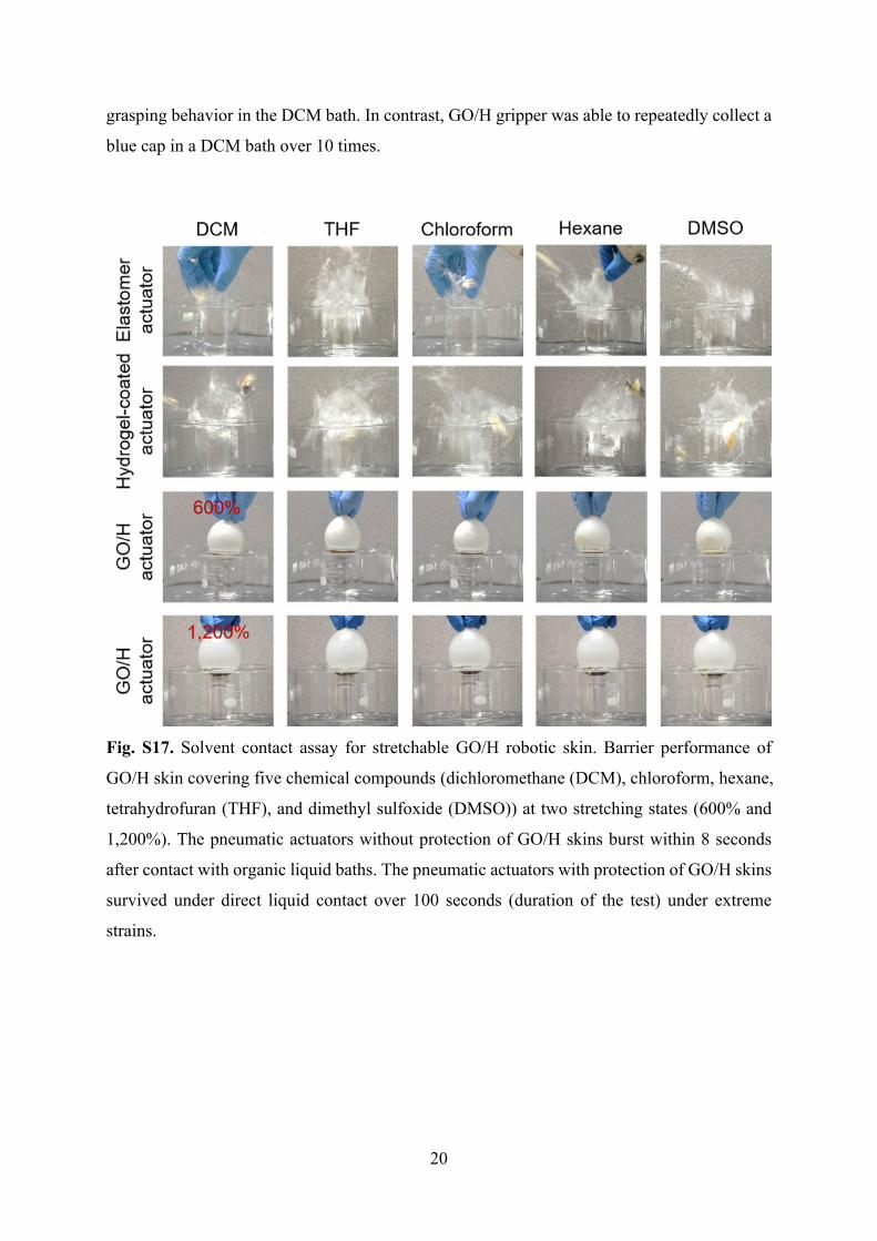
Fig. S17. Solvent contact assay for stretchable GO/H robotic skin. Barrier performance of
GO/H skin covering five chemical compounds (dichloromethane (DCM), chloroform, hexane,
tetrahydrofuran (THF), and dimethyl sulfoxide (DMSO)) at two stretching states (600% and
1,200%). The pneumatic actuators without protection of GO/H skins burst within 8 seconds
after contact with organic liquid baths. The pneumatic actuators with protection of GO/H skins
survived under direct liquid contact over 100 seconds (duration of the test) under extreme
strains.

21
Fig. S18. High-resolution characterization of barrier performance. Gas chromatography (GC)
results of continuous DCM permeation across various barriers into an acetone reservoir. (a)
Bare elastomer. (b) Hydrogel-coated elastomer. (c, d) GO/H-protected elastomer under areal
strains of 600% and 1,200%, respectively.

22
Fig. S19. Zoomed-in photos of the GO/H gripper before and after working in DCM for long
time. The GO/H skin remained intact after multiple times of DCM exposure. Scale bar, 1 cm.
Fig. S20. Heat regulation performances of robotic skins protected elastomers upon direct
exposures to flame. (a) Optical photos and (b) schematic illustration of the setup for surface
temperature measurement. (c) Temperature profiles of the elastomer surface upon exposures
to flame under the protection of different robotic skins.

23
Fig. S21. Effects of hydrogel hydration degree on the (a) heat regulation and (b) fire retardant
performances of MMT/H layer.
Fig. S22. I–V curves of MXene/H skins. With the MXene thicknesses of 4, 6, and 13 µm, the
electrical conductivities of MXene/H skins were extracted to be 1.20 × 10³, 3.97 × 10³, and
1.03 × 10⁴ S m–1, respectively.

24
Fig. S23. Biofilm assay quantifications. Relative biofilm formation of S. aureus and E. coli on
gelatin hydrogel and MXene/H skin.
Fig. S24. Effect of hydration degree on the sensing performance of M-H layer. (a) The water
content of an M-H layer (0.50 wt.% MXene) decreased with time at room temperature at the
relative humidity of 58.0%. (b) Gauge factors (GF) of M-H layers with different water contents.
25
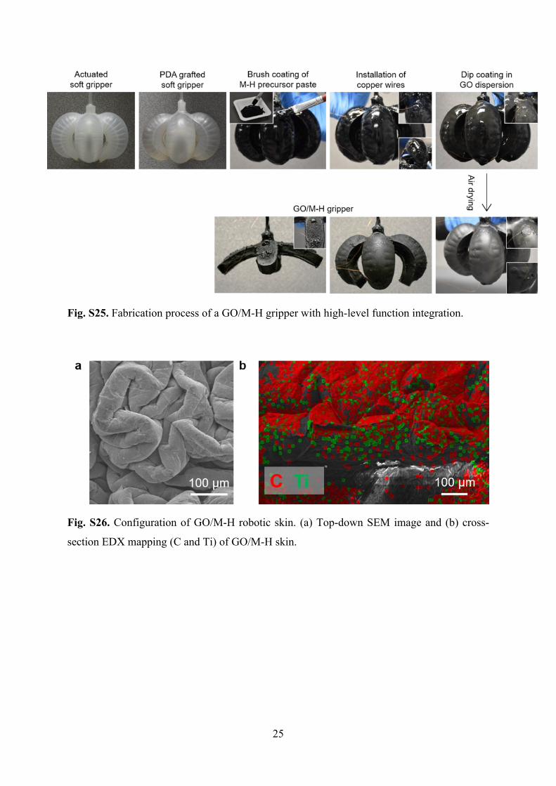
Fig. S25. Fabrication process of a GO/M-H gripper with high-level function integration.
Fig. S26. Configuration of GO/M-H robotic skin. (a) Top-down SEM image and (b) cross-
section EDX mapping (C and Ti) of GO/M-H skin.
26
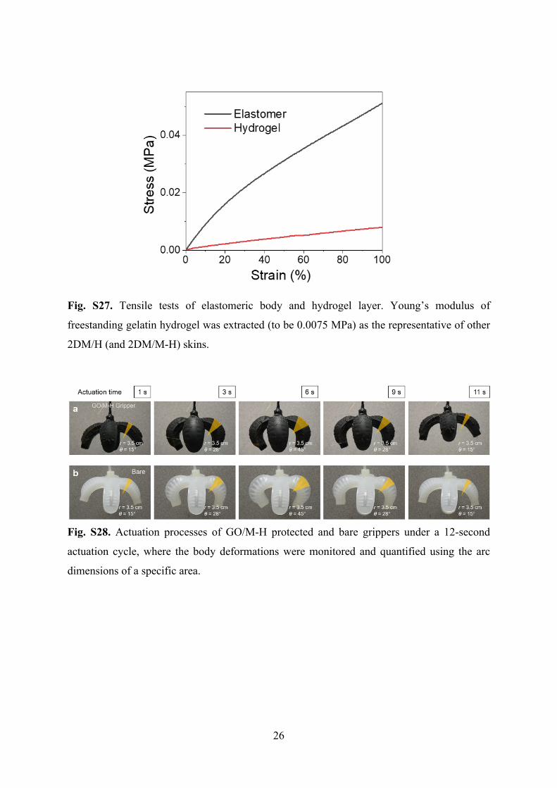
Fig. S27. Tensile tests of elastomeric body and hydrogel layer. Young’s modulus of
freestanding gelatin hydrogel was extracted (to be 0.0075 MPa) as the representative of other
2DM/H (and 2DM/M-H) skins.
Fig. S28. Actuation processes of GO/M-H protected and bare grippers under a 12-second
actuation cycle, where the body deformations were monitored and quantified using the arc
dimensions of a specific area.

27
Fig. S29. Assembly of a dual-bellows walker robot.
28
Fig. S30. GO/H-protected batoid-like robot under continuous rinsing of DCM liquid.
Fig. S31. Swimming traces of bare and GO/H-protected batoid-like robots before and after
liquid DCM rinsing for 10 minutes (in Y-Z plane).

29
Note S1. Reaction details of gelatin crosslinking.
After a small amount of glutaraldehyde (0.40 wt.%) was added into the precursor solution of
gelatin hydrogel at a near-neutral pH value, the highly reactive aldehyde groups of
glutaraldehyde instantaneously reacted with the free amine groups of gelatin. The crosslinking
reaction that first took place was the formation of imine derivatives (Schiff base bonds)
between gelatin and glutaraldehyde, as shown in Fig. S32. As more and more amino acids on
the polypeptide chains of gelatin started to crosslink, the viscosity of gelatin paste started to
increase. The viscous paste was then deposited through various scalable coating techniques,
including brush coating, dip coating, and drop casting.
R' NH2 H C R''
O
R'HN C
OH
H
R''
H+
R' N C
H
R''
HH2O
Gelatin Glutaraldehyde
Schiff base
Fig. S32. Reaction details of gelatin crosslinking.

30
Note S2. Delamination test details.
The delamination tests were conducted to determine the adhesion energies of
elastomer/hydrogel interfaces before and after PDA treatment as well as to compare the
adhesion energies of GO/hydrogel interfaces prepared by cation-induced self-assembly and
direct GO thin film transfer. Mechanical delamination tests were conducted by using a
Universal Testing System (Instron 5543, Instron, Canton, MA). As shown in Fig. S33a, to
measure the adhesion energy of GO/hydrogel interface, a certain area of the GO nanolayer was
glued to another substrate (the square area circled with a white dashed line). During the tension
of GO/gelatin device, this certain area of GO was peeled off from the hydrogel, and the
delamination force was recorded. The adhesion stress was calculated by the loading force
divided by the delaminated area, and the binding energy between GO and hydrogel was
obtained by integrating the area of the corresponding curves in Fig. 1e (left). To measure the
adhesion energy of elastomer/hydrogel interface, one side of the elastomer square was first
glued to the glass slide (the square area circled with a green dashed line), as shown in Fig.
S33b. The other side was then drop coated with gelatin precursor and was subsequently
attached to another glass slide during the crosslinking process. During the tension of the
elastomer/gelatin device, this certain area of gelatin was peeled off from the elastomer, and the
delamination force was recorded. The adhesion stress was calculated by the loading force
divided by the delaminated area, and the binding energy between elastomer and hydrogel was
obtained by integrating the area of the corresponding curves in Fig. 1e (right). The adhesion
stress dropped abruptly to 0 at a certain displacement indicates that the certain area of GO
nanolayer was completely detached from the hydrogel surface. Similar tests were also
conducted for the MXene/hydrogel and MMT/hydrogel interfaces to measure their adhesion
energies. All the measurements were repeated at least three times to extract the average values.

31
Fig. S33. Mechanical delamination tests. Schematic illustrations and actual setups of the
mechanical delamination tests for (a) GO/hydrogel and (b) elastomer/hydrogel interfaces.
Note S3. Organic solvent diffusion tests.
Fig. S34 shows a diffusion cell used to quantify the DCM permeation rate across a barrier
sample. To characterize the DCM permeation across the GO/H skin, the side openings of
Chambers A and B were both sealed with the GO/H skins under 1,200% areal strain.
Afterwards, Chambers A and B sealed with stretched GO/H skins were face-to-face aligned
and clamped together tightly. During DCM permeation tests, Chamber A was filled with DCM,
and Chamber B was filled with acetone, and the top openings were sealed with parafilm. 0.5
mL of liquid was taken from Chamber B after 0.5, 1.0, 2.0, 3.0, and 12.0 hours, and the
concentration of permeated DCM was characterized by gas chromatography (GC). A DCM-
acetone mixture with 25 vol.% of DCM was measured as the reference.
Fig. S34. Diffusion cell setup for characterization of DCM permeation across GO/H skins. (a)
Side opening of Chamber A covering with one GO/H skin under 1,200% areal strain. (b) Side
opening of Chamber B covering with one GO/H skin under 1,200% areal strain. (c) Diffusion
cell setup with face-to-face connection of Chambers A and B. During DCM permeation tests,

32
Chamber A was filled with DCM, and Chamber B was filled with acetone. 0.5 mL of liquid
was taken from Chamber B after 0.5, 1.0, 2.0, 3.0, and 12.0 hours, and the concentration of
permeated DCM was characterized by GC.

33
Note S4. Characterization of EMI SE.
As the incident EM radiation encounters a shielding barrier, the EM waves are divided into
three parts, including reflection (R), absorption (A), and transmission (T), as illustrated in
Equation S1,
A + R + T = 1 (1)
The EMI SE is measured in decibels (dB) and defined as the logarithmic ratio of the incident
power (PI) over transmitted power (PT), as shown in Equation S2,
EMI SE (dB) = 10 log (2) 𝑃𝐼
𝑃𝑇
The total EMI SE (SET) is the sum of contributions from reflection (SER), absorption (SEA),
and multiple reflections (SEMR). For a multilayered EMI shielding material with high EMI SE,
the contribution of SEMR is normally merged into the absorption part (SEA), since the re-
reflected waves are absorbed or dissipated as heat in the shielding materials. Therefore, the SET
can be simplified as Equation S3,
SET = SEA + SER (3)
By using the vector network analyzer (VNA), four parameters (|S11|, |S12|, |S21|, |S22|) are
obtained in the EMI shielding tests and can be used to calculate reflection (R) and transmission
(T) in Equation S4 and S5,
R = ∣S11∣2 = ∣S22∣2 (4)
T = ∣S12∣2 = ∣S21∣2 (5)
SER and SEA can be derived in Equation S6 and S7,
SER = 10 log (6)( 1
1 ‒ ∣𝑆11∣2)
SEA = 10 log (7)(1 ‒ ∣𝑆11∣2
∣𝑆21∣2 )EMI shielding efficiency is also used to express the EM shielding abilities of a material and
can be obtained by using Equation S8,

34
EMI shielding efficiency (%) = × 100% (8)
(100 ‒1
10
Ⅰ𝑆𝐸𝑇Ⅰ
10)

35
Fig. S35. Setup of EMI shielding measurement. (a) Contribution of EM absorption (SEA) and
EM reflection (SER) to total EMI SE (SET) of MXene/H skins with different thicknesses of
MXene nanolayers at the frequency of 8.9 GHz. (b) Vector network analyzer. (c) MXene/H
skin was stabilized by double-sided tapes on the Cu calibration kit.
36
Supplementary References
1. K. Li, T.-H. Chang, Z. Li, H. Yang, F. Fu, T. Li, J. S. Ho and P.-Y. Chen, Adv. Energy
Mater., 2019, 9, 1901687.
2. T. V. Truong, presented in part at the 2019 IEEE/RSJ International Conference on
Intelligent Robots and Systems (IROS), Macau, November, 2019.
3. H. Zhu, T. Kuang, B. Zhu, S. Lei, Z. Liu and S. P. Ringer, Nanoscale Res. Lett., 2011, 6,
331.
4. N. N. Jason, M. D. Ho and W. Cheng, J. Mater. Chem. C, 2017, 5, 5845-5866.