(supplement regarding mox-fuel)en.gosnadzor.ru/framework/nuclear/np-006-98.pdf · 3 summary this...
TRANSCRIPT

Nuclear Safety Institute of the Russian Academy of Sciences (IBRAE RAS)
Moscow E32S2R2eng-FRD 2003
APPROVED BY
L.A. Bolshov,
Director, IBRAE RAS
«___» _________ 2003
APPROVED BY
A.I. Kislov,
Head of 3 rd Department, Gosatomnadzor of Russia
«___» _________ 2003 APPROVED BY
S.A. Adamchik,
Head of 2 nd Department, Gosatomnadzor of Russia
«___» _________ 2003
Requirements to Contents of Safety Analysis Report of Nuclear Power Plant with VVER Reactors
(Supplement regarding MOX-fuel)
Federal standards and rules first version
Project Manager: А. А. Polishuk
Prepared by: N.N. Khrennikov
10 March 2003
Contract: SAV29156/VCH-GAN_RD-32
Phase: 2

2
Federal Nuclear and Radiation Safety Authority of R ussia
(Gosatomnadzor of Russia)
──────────────────────────────────────────────────────────────── FEDERAL STANDARDS AND RULES
IN THE FIELD OF USE OF ATOMIC ENERGY ────────────────────────────────────────────────────────────────
Approved by Order of Gosatomnadzor of Russia
REQUIREMENTS
TO CONTENTS OF SAFETY ANALYSIS REPORT OF NPP WITH VVER REACTORS
(NP-006-98)
EFFECTIVE SINCE
───────────────────────────────────────────────────────────────
MOSCOW 2003 ────────────────────────────────────────────────────────────────

3
SUMMARY
This document lists requirements set forth by Gosatomnadzor of Russia for the contents and format of the Safety Analysis Report of nuclear power plants with VVER-type reactors, which is to be submitted in a documentary package to justify the application to obtain the NPP construction or operation license.
Basing on the SAR NPP information Gosatomnadzor of Russia assesses sufficiency of justifications of siting, construction, commissioning, operation and decommissioning of NPP on the concrete site for the purpose of avoidance of the exceeded exposure doses to the personnel and population and standards regarding releases and content of radioactive substances in the natural environment during normal operation and design basis accidents as well as the possibility of limiting this impact during beyond design basis accidents.
The requirements to SAR NPP contents may be applied to other types of NPPs considering their features.
Requirements of this document shall serve as the guidance for enterprises which plan to carry out activities associated with development, construction and operation of NPPs.
This document has been updated considering the use in the charge of VVER-1000 reactor of fuel assemblies made with the weapons plutonium fuel. The changes are done to Sections 4 and 9.

4
LIST OF ABBREVIATIONS
ASS Automatic Standby Start ACA Accident Confining Area ALARA As Low As Reasonably Acceptable AM Accident Management APCS Automated Process Control System AR Absorber Rod ARSMS Automated Radiation Situation Monitoring System ASW Air Shock Wave AT Air Trap BA Burnable Absorber BAS Burnable Absorber Rod BRU-A Fast Acting Atmospheric Exhaust Station BRU-K Fast Acting Steam Dump Station CA Controlled Area CAD Computer-Aided Design CAR Computer-Aided Research CD TM Civil Defense Technical Measures CfSS Confinement Safety Systems CPS Control and Protection System CPS rod Control and Protection System rod CS Containment System CSS Controlling Safety Systems DBE Design Basis Earthquake DGP Dangerous Geological Processes EAS Emergency Alarm System ECCS Emergency Core Cooling System EFP Electro-Feeding Pump EI External Impacts EIA Environmental Impact Assessment EIS Enterprise Internal Standard EPS Emergency Protection System EPSS Emergency Power Supply Systems ESP Emergency Shutdown Panel FA Fuel Assembly FAS Fast-Acting Station FFSF Fresh Fuel Storage Facility FSAR Final Safety Analysis Report GOST State Standard GP General Provisions for Welding and Overlaying of Equipment and Pipelines
of Nuclear Power Installations GTR General Technical Requirements HP Hold-up Pool HPR High Pressure Re-heater I&C Instrumentation and Controls IAC Inter-Agency Commission ICM In-Core Monitoring IIS Internal Industry Standard ILAC Industry Library of Algorithms and Codes INF Irradiated Nuclear Fuel LOC Loss-Of-Coolant MBA Material Balance Area MCC Main Circulation Circuit MCL Minimum Controlled Level MCP Main Circulation Pump
5
MCR Main Control Room MG Methodological Guide MII Man-Induced Impacts MPa MegaPascal NF Nuclear Fuel NM Nuclear Materials NOC Normal Operation Conditions NPI Nuclear Power Installation NPP Nuclear Power Plant NRHF Nuclear and Radiation Hazardous Facilities NSGP Nuclear Steam Generating Plant OO Operating Organization OPB General Safety Provisions for Nuclear Power Plants PC Power Controller PHRS Passive Heat Removal System PIE Postulated Initiating Event PLC Power Limitation Controller PNAE Rules and standards in the field of nuclear power PORV Pilot Operated Relief Valve PPM Planned Preventive Maintenance PPS Physical Protection System PS Passive Sprinkler PSA Probabilistic safety Analysis PSAR Preliminary Safety Analysis Report PVSAR Preliminary Version of Safety Analysis Report QAP NPP Quality Assurance Program of Nuclear Power Plant R&D Research and Development RadS Radioactive Substances RAP Reliability Assurance Program RD Regulatory Document RI Rules of Inspection of Welded joints and Overlays of Equipment and Piping
of Nuclear Power Installations RI Reactor Installation RIs Reactor Internals RMB Radiation Monitoring Board RNS Rules of Nuclear Safety RPS Reinforced steel Protective Structure RRS NPP Rules of Radiation Safety of Nuclear Power Plants RS Radiation Shelter RTD Regulatory and Technical Document RW Radioactive Waste RWC Reactor Water Chemistry SAO Satrt-up and Alignment Operations SAR NPP Safety Analysis Report of Nuclear Power Plant SC Short Circuit SCC Short Circuit Current SCR Self-sustained Chain Reaction SDGS Stand-by Diesel Generator Power Station SDS Stressed-Deformed State SFSF Spent Fuel Storage Facility SG Steam Generator SIS Safety Important Systems SNF Spent Nuclear Fuel SNiP Construction standards and regulations SPS Safety Protective Systems SPS Seismic Protection System SS Safety Systems

6
SSE Safe Shutdown Earthquake SSS Supporting Safety Systems SV Safety Valve SWT Spare and Wearing Tools TC Technical Conditions TGD Technical Guidance Documents TP Transportation Package UC TSJ Unified Contents of Technical Safety Justification UCMS Unit Control and Monitoring System VVER water-water power reactor (WWER – IAEA)
7
TABLE OF CONTENTS
PHASE: 2 ...................................................................................................................................1
GENERAL REQUIREMENTS ..................................................................................................17
1. REPORT PURPOSE AND SCOPE ................................................................................................17 2. REPORT PREPARATION PROCEDURE ........................................................................................17 3. REQUIREMENTS FOR REPORT CONTENT, FORMAT AND UPDATING.............................................18
3.1. Requirements for content...............................................................................................18 3.2. Requirements for report format and updating................................................................19
APPENDIX.................................................................................................................................20
INTRODUCTION .......................................................................................................................22
1. BASIS OF THE DESIGN DEVELOPMENT ......................................................................................22 2. GENERAL DESCRIPTION OF NPP..............................................................................................22 3. DEVELOPMENT STAGE .............................................................................................................22 4. INFORMATION ON SAFETY ANALYSIS REPORT DEVELOPERS .....................................................22 5. DESCRIPTION OF REPORT ........................................................................................................22
CHAPTER 1. GENERAL DESCRIPTION OF NUCLEAR POWER PLA NT ....................23
1.1. CONSTRUCTION CONDITIONS ...........................................................................................23 1.2. SITING PLAN ....................................................................................................................23 1.3. DESCRIPTION OF NPP CIRCUIT DIAGRAM .........................................................................24 1.4. MAIN TECHNICAL CHARACTERISTICS OF NPP...................................................................24 1.5. POWER GRID CHARACTERISTICS ......................................................................................24 1.6. NPP OPERATIONAL MODES..............................................................................................25 1.7. NPP SAFETY ENSURANCE CONCEPT ................................................................................25
1.7.1. Main safety principles and criteria of NPP ............................................................25 1.7.2. Nuclear safety........................................................................................................26 1.7.3. Radiation safety .....................................................................................................26 1.7.4. Fire safety ..............................................................................................................26 1.7.5. Protection of NPP from natural and man-induced impacts ..................................27 1.7.6. Plans of measures to protect personnel and population in case of accidents .....28
1.8. SAFETY QUANTITATIVE ANALYSIS RESULTS ......................................................................28 1.8.1. Reliability of equipment and other components....................................................28 1.8.2. Deterministic safety analysis .................................................................................28 1.8.3. Probabilistic safety analysis ..................................................................................29
1.9. MAIN TECHNICAL SOLUTIONS ...........................................................................................29 1.9.1. Reactor, primary circuit and related systems........................................................29 1.9.2. Steam turbine ........................................................................................................30 1.9.3. Circulation and service water supply system........................................................30 1.9.4. Electric systems.....................................................................................................30 1.9.5. NPP water chemistry .............................................................................................31 1.9.6. Fuel handling system.............................................................................................32 1.9.7. Radioactive waste management ...........................................................................32 1.9.8. NPP process control system .................................................................................32 1.9.9. Safety systems ......................................................................................................33 1.9.10. NPP general layout and arrangement...................................................................33 1.9.11. Ventilation systems................................................................................................34 1.9.12. Radiation shielding and radiation monitoring........................................................35 1.9.13. Physical protection system....................................................................................35 1.9.14. Fire safety measures .............................................................................................36
8
1.10. BRIEF DESCRIPTION OF NPP OPERATION.....................................................................37 1.11. NPP ENVIRONMENTAL IMPACT ASSESSMENT ...............................................................40 1.12. COMPARISON WITH SIMILAR DOMESTIC AND FOREIGN NPP DESIGNS............................41 1.13. NPP CONSTRUCTION SCHEDULE, PARTNERS AND CONTRACTORS ................................41 1.14. PRINCIPLE PROVISIONS FOR NPP OPERATION ORGANIZATION......................................41
1.14.1. NPP commissioning ..............................................................................................41 1.14.2. Management of NPP operations ...........................................................................42 1.14.3. Safe operation limits and conditions .....................................................................42 1.14.4. NPP unit decommissioning ...................................................................................42
1.15. QUALITY ASSURANCE ..................................................................................................42
CHAPTER 2. NPP SITE AND REGION CHARACTERISTICS ..........................................44
2.1. DESCRIPTION OF NPP SITE LOCATION REGION ................................................................44 2.1.1. Geographic location...............................................................................................44 2.1.2. Topographic conditions .........................................................................................45 2.1.3. Demography ..........................................................................................................45
2.2. NPP TECHNOLOGICAL ENVIRONMENT ..............................................................................46 2.2.1. Base material to determine quantitative-probabilistic characteristics and parameters of external man-induced impacts.......................................................................46 2.2.2. Forecasting methods for characteristics and parameters of external man-induced impacts 48 2.2.3. Assessment results of characteristics and parameters of external man-induced impacts 48
2.3. HYDRO-METEOROLOGICAL CONDITIONS...........................................................................49 2.3.1. Regional climatology .............................................................................................49 2.3.2. Meteorological and hydrological conditions ..........................................................50 2.3.3. Base materials for determining quantitative-probabilistic characteristics and parameters of hydro-meteorological processes and phenomena ........................................50 2.3.4. Methods of calculation of characteristics and parameters of hydro-meteorological processes and phenomena ...................................................................................................51
2.4. GEOLOGICAL, HYDRO-GEOLOGICAL, SEISMO-TECTONIC AND ENGINEERING AND
GEOLOGICAL CONDITIONS ............................................................................................................53 2.4.1. Basic materials for analysis of geological, hydro-geological, seismo-tectonic and engineering and geological conditions at NPP site ..............................................................53 2.4.2. Results of analysis of geological, hydro-geological, seismo-tectonic and engineering and geological conditions..................................................................................53 2.4.3. Methods and methodologies to reveal geological and engineering and geological processes and phenomena and to determine characteristics of soils and ground water ....55 2.4.4. Methods for forecasting characteristics and parameters of factors and processes 55
2.5. NPP IMPACT TO ENVIRONMENT AND POPULATION ............................................................55 2.6. OBSERVATION PROGRAMS...............................................................................................56
2.6.1. List of programs .....................................................................................................56 2.6.2. Description of monitoring programs ......................................................................56
2.7. PROVISIONS FOR NORMAL LIFE AND WORK CONDITIONS OF PERSONNEL AND POPULATION IN
NPP LOCATION REGION AND THEIR EMERGENCY EVACUATION ARRANGEMENTS ...........................56 2.8. SUMMARY TABLE WITH A LIST OF EXTERNAL IMPACTS TO NPP SITE ..................................57 2.9. DOCUMENTING OF NPP SITE CONDITIONS INFORMATION..................................................57 ATTACHMENT 2.1 ....................................................................................................................58 3.1. BASIC REGULATORY PRINCIPLES AND CRITERIA OF DESIGN OF BUILDINGS, STRUCTURES, SYSTEMS AND ELEMENTS.............................................................................................................59
3.1.1. List of applicable standards and rules .............................................................59 3.1.2. Assessment of compliance ................................................................................59
9
3.1.3. Waivers, their justification and compensatory measures taken ...................59 3.2. APPLICABLE CATEGORIES OF BUILDINGS, SYSTEMS AND ELEMENTS..................................60
3.2.1. Safety categories of buildings, systems and elements..................................60 3.2.2. Quality classes of equipment and pipelines ....................................................60 3.2.3. Seismic stability classes ....................................................................................60 3.2.4. List of buildings, systems and elements subject to stability analysis regarding natural and man-induced impacts...................................................................60
3.3. DESCRIPTION AND JUSTIFICATION OF LAYOUT SOLUTION ON NPP SITE.............................61 3.4. PROBABLE SCENARIOS OF NATURAL OR MAN-INDUCED INITIATING EVENTS’ CONSEQUENCES
ON NPP SITE ...............................................................................................................................62 3.5. PARAMETERS OF IMPACTS CAUSED BY ACCIDENTS ON NPP SITE .....................................62
3.5.1. Impacts caused by accidents at NPP beyond Main Building ........................62 3.5.2. Impacts caused by accidents within Main Building beyond containment......65 3.5.3. Impacts caused by accidents within containment.................................................66
3.6. IMPACTS ARISING FROM NOC AND TRANSIENTS, THEIR PARAMETERS ..............................67 3.7. DESIGN COMBINATIONS OF LOADS TO NPP BUILDINGS, STRUCTURES AND EQUIPMENT.....67 3.8. SITE PROTECTION FROM HAZARDOUS GEOLOGICAL PROCESSES ......................................67 3.9. FLOOD PROTECTION .......................................................................................................68
3.10.1. Safety important buildings, structures and foundations........................................68 3.10.2. Hydraulic and geo-technical structures, units and channels ................................69 3.10.3. Applicable software ...............................................................................................69 3.10.4. Methods of bench-testing and field studies of building and structures ................69 3.10.5. Criteria of NPP buildings and structures stability..................................................70
3.11. DETERMINATION OF LOADS CAUSED BY NATURAL AND MAN-INDUCED DYNAMIC IMPACTS AND TRANSMITTED THROUGH BUILDING STRUCTURES TO NPP EQUIPMENT, PIPELINES, SYSTEMS
AND ELEMENTS ............................................................................................................................70 3.11.1. Input data for dynamic calculations.......................................................................70 3.11.2. Methods of analysis of structure dynamic behavior.......................................72 3.11.3. Non-seismic dynamic loads...................................................................................74
3.12. BUILDINGS, STRUCTURES, BASEMENTS AND FOUNDATIONS ..........................................75 3.12.1. RTD compliance analysis......................................................................................75 3.12.2. Main Building .........................................................................................................75 3.12.3. Other NPP buildings and structures......................................................................82 3.12.4. Building structure diagnostics ...............................................................................83 3.12.6. Measures to ensure operational applicability of fencing structures of the containment during operation................................................................................................84
3.13. METHODS TO JUSTIFY STRENGTH AND PERFORMANCE OF NPP EQUIPMENT, PIPELINES, SYSTEMS AND ELEMENTS TAKING ACCOUNT OF LOADS CAUSED BY NATURAL AND MAN-INDUCED
IMPACTS AND TRANSFERRED THROUGH STRUCTURES AND BUILDINGS..........................................84 3.13.1. Consideration of external conditions in design of mechanical and electrical equipment ..............................................................................................................................84 3.13.2. Mechanical systems, equipment and pipelines ....................................................85 3.13.3. Electrical equipment ..............................................................................................87 3.13.4. Electrical power equipment ...................................................................................87 3.13.5. Pumps and valves .................................................................................................88 3.13.6. Steam generators ..................................................................................................88 3.13.7. Diesel generators ..................................................................................................88 3.13.8. Instrumentation and controls, APCS equipment ......................................................88 3.13.9. Ventilation equipment, air ducts, filtering equipment ............................................88 3.13.10. Hoisting and transportation equipment .............................................................89 3.13.11. Control rod drive systems of nuclear reactor ....................................................89 3.13.12. Nuclear reactor core elements................................................................................89 3.13.13. Seismic instrumentation and controls .....................................................................90

10
3.13.14. Used software .........................................................................................................90 3.13.15. Testing methods of systems and elements ............................................................91
APPENDIX 3.1...........................................................................................................................92 APPENDIX 3.2 ........................................................................................................................94
CHAPTER 4. REACTOR ..........................................................................................................96
4.1. PURPOSE OF THE REACTOR..................................................................................................96 4.1.1 Purpose and functions .................................................................................................96 4.1.2. Design bases .........................................................................................................96
4.2. REACTOR DESIGN.................................................................................................................96 4.2.1. Description of the reactor ............................................................................................96 4.2.2. Control and monitoring ................................................................................................98 4.2.3. Tests and inspections .................................................................................................99 4.2.4. Analysis of the design .................................................................................................99 4.2.5. Reactor shutdown system - CPS rods......................................................................101 4.2.6. Warning emergency protection system ....................................................................103 4.2.7. Neutronics calculation of the core.............................................................................103 4.2.8. Thermal-hydraulic calculation ...................................................................................105 4.2.9. CPS actuators ...........................................................................................................107 4.2.10. Reactor pressure vessel .........................................................................................108
CHAPTER 5. PRIMARY CIRCUIT AND RELATED SYSTEMS ......................................111
5.1. BRIEF DESCRIPTION.......................................................................................................112 5.1.1. Primary circuit and related systems ....................................................................112 5.1.2. Flow diagram .......................................................................................................113 5.1.3. Instrumentation and control block-diagram.........................................................113 5.1.4. General view drawings ........................................................................................113
5.2. INTEGRITY (STRENGTH AND LEAKTIGHTNESS) OF THE PRIMARY CIRCUIT PRESSURE
BOUNDARIES .............................................................................................................................113 5.2.1. Compliance with standards and rules .................................................................113 5.2.2. Primary circuit overpressure protection ..............................................................114 5.2.3. Primary circuit materials ......................................................................................116 5.2.4. In-service inspections and tests of primary circuit ..............................................117 5.2.5. Detection of leaks through the primary pressure boundaries.............................118 5.2.6. Linkage to the secondary circuit..........................................................................118
5.3. REACTOR PRESSURE VESSEL AND HEAD ........................................................................118 5.3.1. Reactor pressure vessel and head materials .....................................................118 5.3.2. Pressure and temperature design limits .............................................................120 5.3.3. Reactor pressure vessel integrity........................................................................120
5.4. PRIMARY CIRCUIT COMPONENTS....................................................................................121 5.4.1. Main circulation pumps........................................................................................122 5.4.2. Steam generators ................................................................................................122 5.4.3. Pipelines containing primary coolant ..................................................................124 5.4.4. Limitation of steam flow rate through the main steam line .................................124 5.4.5. Main steam line cut-off system............................................................................124 5.4.6. Core cooling system ............................................................................................124 5.4.7. Residual heat removal system ............................................................................124 5.4.8. Pressurizer...........................................................................................................125 5.4.9. Primary pressure maintaining system.................................................................125 5.4.10. Valves ......................................................................................................................125 5.4.11. Safety and relief valves ...........................................................................................125 5.4.12. Main component support structures .......................................................................125

11
CHAPTER 6. STEAM TURBINE ...........................................................................................126
6.1. TURBINE........................................................................................................................126 6.1.1. Design bases .......................................................................................................126 6.1.2. System design .....................................................................................................127 6.1.3. System performance control and monitoring ......................................................128 6.1.4. Test and inspections............................................................................................128 6.1.5. Analysis of design................................................................................................129
6.2. DIRECT STEAM PIPING SYSTEM ......................................................................................130 6.3. FEED WATER SYSTEM ....................................................................................................130 6.4. SYSTEM FOR STEAM DUMPING FROM THE SECONDARY CIRCUIT INTO CONDENSERS OF THE
TURBINE ....................................................................................................................................130 6.5. SECONDARY PROTECTION SYSTEM AGAINST OVERPRESSURE ........................................130 6.6. SECONDARY MAKE-UP SYSTEM ......................................................................................130 6.7. SECONDARY CHEMISTRY AND SYSTEM FOR ITS MAINTAINING..........................................130 6.8. TURBINE CONDENSATE CLEAN-UP SYSTEM.....................................................................130 6.9. SAMPLING SYSTEM FOR SECONDARY PROCESS MEDIA ...................................................130 6.10. JUSTIFICATION OF STRENGTH, RESISTANCE AND OPERABILITY OF PIPELINES, PUMPS, GATE VALVES, MAIN FITTINGS, SAFE AND RELIEF VALVES IN CASE OF NATURAL AND MAN-INDUCED
IMPACTS 130
CHAPTER 7. MONITORING AND CONTROL ....................................................................131
7.1. INTRODUCTION ..............................................................................................................131 7.1.1. Determination of safety important monitoring and control systems and devices 131 7.1.2. Basic safety principles and criteria......................................................................132
7.2. MONITORING AND CONTROL SYSTEMS AND DEVICES ENSURING POWER UNIT NORMAL
OPERATION ...............................................................................................................................132 7.2.1. NPP power unit monitoring and control system..................................................132 7.2.2. Unit control room (MCR) .....................................................................................134 7.2.3. RI monitoring and control systems......................................................................136 7.2.4. RI control and protection systems.......................................................................137
7.3. SYSTEMS AND DEVICES FOR SAFETY SYSTEM MONITORING AND CONTROL .....................139 7.3.1. NPP power unit controlling safety systems.........................................................139 7.3.2. Emergency shutdown panel ................................................................................140
7.4. DEFECT DIAGNOSTIC SYSTEMS AND DEVICES .................................................................140 7.5. SYSTEMS AND DEVICES FOR BARRIER INTEGRITY AND SERVICEABILITY MONITORING ......141 7.6. SYSTEMS AND DEVICES FOR FIRE SAFETY SYSTEM MONITORING AND CONTROL..............141 7.7. SYSTEMS AND DEVICES FOR EXPLOSION-PROOF SYSTEM MONITORING AND CONTROL....141
7.7.1. Systems and devices for unit explosion-proof system monitoring and control ..141 7.7.2. Systems and devices for RI explosion-proof system monitoring and control ....141
7.8. SYSTEMS AND DEVICES FOR PHYSICAL PROTECTION SYSTEM MONITORING AND CONTROL
141 7.9. SYSTEMS AND DEVICES FOR RADIOACTIVE PRODUCT PLANNED RELEASE CONTROL ........141 7.10. ENVIRONMENT MONITORING SYSTEMS AND DEVICES ..................................................141
7.10.1. Environment monitoring systems and devices of controlled area, surveillance area and NPP compartments .....................................................................141 7.10.2. Radiation monitoring systems of NPP power unit compartments..............141
7.11. COMMUNICATION AND WARNING SYSTEMS AND DEVICES ............................................141 7.12. MONITORING AND CONTROL SYSTEMS AND DEVICES WHICH DO NOT AFFECT SAFETY..142
7.12.1. Description...........................................................................................................142 7.12.2. Safety analysis ....................................................................................................142
CHAPTER 8. ELECTRIC POWER SUPPLY .......................................................................143
12
8.1. EXTERNAL POWER GRID ................................................................................................143 8.1.1. Power delivery to the grid....................................................................................143 8.1.2. Power supply system characteristics ..................................................................143
8.2. MAIN ELECTRIC CONNECTIONS ......................................................................................144 8.2.1. General description .............................................................................................144 8.2.3. Fire safety of the main electric connections equipment .....................................145 8.2.4. Main electric connections control posts ..............................................................145
8.3. IN-HOUSE POWER SUPPLY .............................................................................................145 8.3.1. NPP normal operation In-house power supply system.......................................145 8.3.2. Emergency power supply system .......................................................................146 8.3.3. Cable fire protection ............................................................................................150
8.4. OPERATION ...................................................................................................................150 8.4.1. Operating procedures.......................................................................................150 8.4.2. Maintenance procedures ..................................................................................151 8.4.3. Commissioning..................................................................................................151
8.5. COMMUNICATIONS.........................................................................................................151 8.6. STANDARDS AND GUIDELINES ........................................................................................151 8.7. MARKING.......................................................................................................................153
CHAPTER 9. POWER UNIT AUXILIARY SYSTEMS ........................................................154
9.1. NUCLEAR FUEL STORAGE AND HANDLING SYSTEMS.............................................................154 9.1.1. Fresh (unirradiated) nuclear fuel storage and handling system ...............................154 9.1.2. Core refueling system ...............................................................................................158 9.1.3. Spent (irradiated) fuel handling systems ..................................................................160 9.1.4. On-site nuclear fuel transportation system ...............................................................167
CHAPTER 10. RADIOACTIVE WASTE MANAGEMENT ............................................168
10.1. RW GENERATING SOURCES.......................................................................................168 10.2. GASEOUS RW MANAGEMENT SYSTEMS .....................................................................169
10.2.1. Design bases .......................................................................................................169 10.2.2. Description of the systems ..................................................................................170 10.2.3. RadS releases .....................................................................................................171
10.3. LIQUID RW MANAGEMENT SYSTEMS ..........................................................................171 10.3.1. Design bases .......................................................................................................171 10.3.2. Description of the systems ..................................................................................172 10.3.3. RadS discharges .................................................................................................173
10.4. SOLID RW MANAGEMENT SYSTEM .............................................................................173 10.4.1. Design bases .......................................................................................................173 10.4.2. Description of the systems ..................................................................................174
10.5. RADIATION MONITORING AND SAMPLING SYSTEM .......................................................175 10.5.1. Design bases .......................................................................................................175 10.5.2. Description of the systems ..................................................................................175
CHAPTER 11. RADIATION PROTECTION ....................................................................177
11.1. MINIMUM ACHIEVABLE LEVEL OF THE OCCUPATIONAL EXPOSURE (ALARA PRINCIPLE)177 11.1.1. Radiation safety concept .....................................................................................177 11.1.2. Design bases .......................................................................................................177 11.1.3. Organization of the operation ..............................................................................178
11.2. RADIATION SOURCES.................................................................................................178 11.2.1. Equipment containing the RadS..........................................................................178 11.2.2. Gaseous RadS generating sources ....................................................................179
11.3. ACCOUNTING OF THE FEATURES OF RADIATION PROTECTION DESIGN ........................179 11.3.1. Layout and configuration of the buildings, structures and equipment ................179

13
11.3.2. Design features of the systems and equipment components.............................179 11.3.3. Biological shielding ..............................................................................................180 11.3.4. Ventilation, filtration and conditioning systems ...................................................180 11.3.5. Radiation and health physics monitoring system................................................181
11.4. OCCUPATIONAL DOSE ESTIMATION FOR NPP OPERATIONS AND ACCIDENTS AT NPP ..181 11.5. RADIATION SAFETY PROGRAM ...................................................................................182
11.5.1. Organization ........................................................................................................182 11.5.2. Radiation monitoring program.............................................................................182 11.5.3. Medical care and protection of personnel health ................................................184
APPENDIX 11-1 .....................................................................................................................186
CHAPTER 12. SAFETY SYSTEMS ......................................................................................187
12.1. PROTECTIVE SAFETY SYSTEMS ..................................................................................187 12.1.1. Description of systems ........................................................................................187 12.1.2. Emergency core cooling and emergency boron injection systems, emergency feedwater supply system for SG, systems to protect the primary and secondary circuit against overpressure ...........................................................................................................190
12.2. CONFINING SAFETY SYSTEMS ....................................................................................195 12.2.1. General description and design bases................................................................195 12.2.2. Leaktight compartment system ...........................................................................198 12.2.3. Pressure reduction, heat removal, hydrogen evacuation and gas-aerosol clean-up systems...........................................................................................................................201 12.2.4. Tests of CfSSs and their components ................................................................204 12.2.5. Content and maintenance of CfSS during operation ..........................................207
12.3. SUPPORTING SAFETY SYSTEMS .................................................................................207 12.3.1. Design bases .......................................................................................................208 12.3.2. Design of the system ...........................................................................................208 12.3.3. Control and monitoring of the system operation .................................................209 12.3.4. Tests and inspections..........................................................................................209 12.3.5. Evaluation of the design ......................................................................................209 12.3.6. Additional information ..........................................................................................210
CHAPTER 13. OPERATION ..................................................................................................213
13.1. OO ORGANIZATIONAL STRUCTURE.............................................................................213 13.1.1. Structure of management and technical support ................................................213 13.1.2. NPP operations department ................................................................................214 13.1.3. Personnel qualification ........................................................................................215
13.2. PERSONNEL TRAINING ....................................................................................................215 13.2.1. Organization of personnel training ......................................................................215 13.2.2. Co-ordination (correlation of stages) of personnel training with SAO and fuel loading. Staffing plan ...........................................................................................................215 13.2.3. Maintaining personnel qualification level ............................................................215
13.3. MANUALS, PROCEDURES.................................................................................................216 13.3.1. Development of manuals, procedures ................................................................216 13.3.2. Job descriptions...................................................................................................216 13.3.3. Operating procedures..........................................................................................216 13.3.4. Emergency procedures .......................................................................................216 13.3.5. Accident Management Guide ..............................................................................217
13.4. MAINTENANCE AND REPAIR........................................................................................217 13.4.1. Annual plans of equipment maintenance and repair ..........................................217 13.4.2. Maintenance conditions.......................................................................................217
13.5. ORGANIZATION OF CONTROL AND SUBMISSION OF INFORMATION ON THE PLANT SAFETY
LEVEL 217

14
13.5.1. Control by OO representatives............................................................................217 13.6. PHYSICAL PROTECTION (SECURITY) OF THE PLANT.....................................................218
13.6.1. Composition of physical protection and related requirements............................218 13.6.2. PPS chart and organizational structure ..............................................................219
13.7. EMERGENCY PLANNING .............................................................................................219 13.7.1. Protection of personnel .......................................................................................219 13.7.2. Population and environmental protection............................................................221 13.7.3. Emergency response operations centers on NPP site and in satellite-city (settlement)..........................................................................................................................222 13.7.4. Elimination of accident consequences................................................................222 13.7.5. Emergency drills ..................................................................................................223
CHAPTER 14. COMMISSIONING .........................................................................................224
14.1. REQUIREMENTS TO INFORMATION CONTAINED IN PSAR....................................................224 14.1.1. Scope and organization of work, personnel ...........................................................224 14.1.2. Stages of work.........................................................................................................225 14.1.3. Test programs .........................................................................................................226 14.1.4. Work and tests schedule.........................................................................................227 14.1.5. Additional requirements to NPP power unit commissioning...................................227
14.2. REQUIREMENTS TO FSAR INFORMATION ..........................................................................228 14.2.1. Organization and personnel ....................................................................................228 14.2.2. Stages of work.........................................................................................................228 14.2.3. Test program ...........................................................................................................228 14.2.4. Work and test schedule...........................................................................................228 14.2.5. Additional requirements to the NPP power unit commissioning ............................229
APPENDIX 14-1 .........................................................................................................................230
CHAPTER 15. ACCIDENT ANALYSIS ................................................................................232
15.1. LIST OF DESIGN BASIS ACCIDENTS .............................................................................232 15.1.1. Classification of initiating events .........................................................................232 15.1.2. Initiating event causes and identification ............................................................233 15.1.3. Possible evolution analysis for the situations connected with an initiating event 233 15.1.4. List of design basis accidents .............................................................................233
15.2. LIST OF BEYOND DESIGN BASIS ACCIDENTS................................................................233 15.2.1. Scenarios of beyond design basis accidents which result in increased radionuclide releases to the environment. NPP vulnerable points.....................................233 15.2.2. Typical groups of beyond design basis accident scenarios ...............................234 15.2.3. Representative scenarios of beyond design basis accidents.............................234 15.2.4. List of beyond design basis accidents ................................................................234
15.3. ANALYSIS METHODOLOGIES.......................................................................................234 15.3.1. List of applied methodologies..............................................................................234 15.3.2. Description of mathematical models ...................................................................234 15.3.3. Assumptions and errors of computation methodologies ....................................235 15.3.4. Scope of computation methodologies.................................................................235 15.3.5. Information on computation software verification ...............................................235
15.4. COMPUTATION INPUT DATA ........................................................................................236 15.4.1. Geometry input data ............................................................................................236 15.4.2. Physical input data ..............................................................................................236 15.4.3. Process input data ............................................................................................237 15.4.4. Topological input data .........................................................................................237 15.4.5. Reference conditions...........................................................................................238
15.5. DESIGN BASIS ACCIDENT ANALYSIS .................................................................................238
15
15.5.1. Description of event and system performance sequence ..................................238 15.5.2. Safety assessment criteria ..................................................................................238 15.5.3. Analysis of computation results...........................................................................238 15.5.4. Conclusion ...........................................................................................................240
15.6. ANALYSIS OF BEYOND DESIGN BASIS ACCIDENTS. DEVELOPMENT OF MEASURES FOR
BEYOND DESIGN BASIS ACCIDENT MANAGEMENT. .......................................................................240 15.6.1. Description of sequence of events, system performance (failure) under beyond design basis accidents ........................................................................................................240 15.6.2. Results of computation analysis..........................................................................241 15.6.4. Assessment of efficient measures proposed to manage beyond design basis accident 243 15.6.5. Conclusion ...........................................................................................................243
ANNEX 15-1 ............................................................................................................................244 ANNEX 15-2 ............................................................................................................................247 ANNEX 15-3 ............................................................................................................................248 ANNEX 15-4 ............................................................................................................................249 ANNEX 15-5 ............................................................................................................................251
CHAPTER 16. SAFE OPERATION LIMITS AND CONDITIONS. OPERATIONAL LIMITS. .......................................................................................................................................253
16.1. SAFE OPERATION LIMITS ............................................................................................253 16.1.1. List of monitored parameters and safe operation limiting values .......................253 16.1.2. SS actuation settings...........................................................................................253
16.2. OPERATIONAL LIMITS .................................................................................................254 16.2.1. Limiting values of process parameters ...............................................................254 16.2.2. Process protection features, interlocks and feedback controllers with actuation settings 254
16.3. SAFE OPERATION CONDITIONS...................................................................................254 16.3.1. Power levels and valid normal operation modes ................................................254 16.3.2. Safe operation conditions and composition of serviceable systems and equipment required for NPP power unit commissioning and operation under permissible modes 254 16.3.3. Permissible power levels and reactor power operation time period under deviation from safe operation conditions ............................................................................255 16.3.4. Conditions for SIS maintenance, testing and repair ...........................................255
16.4. ADMINISTRATIVE CONDITIONS AND RECORD-KEEPING REGARDING SAFE OPERATION
LIMITS AND CONDITIONS MONITORING DATA ...............................................................................255
CHAPTER 17. QUALITY ASSURANCE ..............................................................................256
17.1. GENERAL PROVISIONS...............................................................................................256 17.1.7. Structure of Chapter 17 of SAR NPP ..................................................................257 19. Quality assurance documentation (records) ........................................................................259
17.2. REQUIREMENTS TO THE INFORMATION ON QUALITY ASSURANCE ACTIVITY ..................259 17.2.1. Organization ........................................................................................................259 17.2.1.1. Quality assurance policy...................................................................................259 17.2.2. Quality assurance programs ...............................................................................261 17.2.3. Design control......................................................................................................261 17.2.4. Supply-related documentation control ................................................................262 17.2.5. Instructions, methodologies and drawings..........................................................262 17.2.6. Document control ................................................................................................263 17.2.7. Supervision over materials, equipment, instrumentation and services supplied263 17.2.8. Identification and control of materials, equipment and components ..................264 17.2.9. Process control ....................................................................................................264
16
17.2.10. Inspections ............................................................................................................265 17.2.11. Test control............................................................................................................265 17.2.12. I&C and test equipment verification ......................................................................265 17.2.13. Quality assurance of computations, software and computation methodologies..266 17.2.14. Equipment handling, storage and transportation..................................................267 17.2.15. Reliability assurance .............................................................................................267 17.2.16. Equipment examination, testing and operational state ........................................267 17.2.17. Non-compliance control ........................................................................................268 17.2.18. Corrective measures .............................................................................................268 17.2.19. Quality assurance documentation (records).........................................................268 17.2.20. Audits ...............................................................................................................269
CHAPTER 18. DECOMMISSIONING ..................................................................................270
18.1. DECOMMISSIONING CONCEPT ....................................................................................270 18.2. RADIATION SOURCES.................................................................................................270 18.3. RADIATION MONITORING ............................................................................................271 18.4. MATERIALS OF UNLIMITED USAGE (RECYCLED MATERIALS).........................................271 18.5. DECOMMISSIONING MEASURES, SYSTEMS AND EQUIPMENT........................................272

17
GENERAL REQUIREMENTS
1. Report purpose and scope
1.1. The Safety Analysis Report of Nuclear Power Plant (hereinafter SAR NPP) is developed by OO and submitted to Gosatomnadzor of Russia as a constituent of the document package justifying the application to obtain a license from Gosatomnadzor of Russia for construction or operation of NPP.
1.2. SAR NPP shall contain information, which is sufficient for adequate understanding by Gosatomnadzor of Russia of the NPP design, safety concept the design is based on, Quality Assurance Program and basic principles of operation as proposed by the Applicant.
Gosatomnadzor of Russia, basing on the information contained in SAR NPP, shall have an opportunity to assess whether the safety justification is sufficient with regard to siting, construction, operation or decommissioning of NPP at the specific site to exclude exposure of the personnel and population beyond the established dose values and guidelines for releases and discharges and RadS content in the environment during normal operation and design basis accidents, as well as for a possibility to limit radiation impacts in case of beyond design basis accidents.
1.3. A separate SAR shall be developed for each power unit of multi-unit nuclear power plants.
1.4. Requirements for safety Analysis Report for NPPs with VVER type reactor (hereinafter – the requirements) have been developed for NPPs with VVER reactor. Their many provisions, however, are applicable for other types NPPs. When the requirements are used for other NPPs, the nuclear plants’ features and differences from NPPs with VVER reactors shall be taken into account.
2. Report preparation procedure
2.1. The activities related to preparing, compiling and necessary updating of SAR shall be carried out at all stages of NPP life cycle.
SAR NPP shall correspond to the state of NPP as-designed as well as as-built.
2.2. PSAR NPP shall be submitted along with the application for a NPP construction license (permit) with FSAR NPP being submitted by the moment of NPP operating license application submission.
The PSAR NPP information shall be based on NPP design documentation, technical designs of RI and SIS.
The FSAR information shall correspond to the actual state of NPP after construction, manufacturing, assembling, start-up and alignment operations, first criticality and first power. At this, the operating license (permit) is to be obtained in two stages:
• preliminary license (permit) – before the first core charge is loaded;
• final license – before commissioning for commercial operation.
2.3. To obtain the relevant preliminary operating license (permit) the PVSAR NPP containing the information required for FSAR NPP on the state as of the beginning of the first loading of fuel shall be available by the loading of the first fuel charge into the reactor.
As the NPP commissioning progresses the PVSAR NPP shall grow into FSAR NPP by its completion.
2.4. All changes done to the initial design during modernizations after the first SAR NPP submission shall be reflected in the report and assessed in terms of the NPP safety impact.
18
3. Requirements for report content, format and upda ting
The SAR NPP content and format as well as its updating shall correspond to this document. If followed it ensures acceptability of the information presented in SAR NPP by Gosatomnadzor of Russia and shortest review time.
It is permitted to deviate from the required format provided the content is adequate. At this, the Applicant shall bear in mind that significant deviations may unfavorably affect the SAR NPP review timeframe by the regulatory authority or cause its return to the Applicant without a review.
3.1. Requirements for content
3.1.1. The SAR NPP content shall be, as practicably possible, such that the regulatory authority would not need to additionally review design or operation documentation. All design or other documentation (scientific reports) referenced to in SAR NPP shall be submitted along with SAR NPP.
3.1.2. The PSAR and FSAR structure shall be unified and correspond to “Table of Contents” section of this document.
In case the documentation preparedness degree at the PSAR development stage does not meet the requirement of this document the information presented in SAR NPP shall reflect the actual state of the level of development and safety justification. The following shall be additionally presented:
1. Criteria used for development and a list of data and prerequisites justifying that they will be achieved.
2. Proposed design solutions and alternative options.
3. Work completion schedule with the necessary information delivery timeframes.
3.1.3. When SAR NPP is submitted as a justification material for the application to obtain the local permit to shift from one stage to the next one the scope and information justification degree shall be determined by the Applicant basing on the condition of sufficiency of the submitted justifications as agreed upon with Gosatomnadzor of Russia.
3.1.4. The information shall be presented in clear and precise manner and free from ambiguity and wordiness. The information on meeting of the requirements shall not be declarative and supported by documentary evidence that they are met.
While presenting the information on the systems one shall follow the description structure given in Appendix to this document.
3.1.5. The duplication of information shall be avoided. If the same information is required for different SAR NPP sections related to different sections of the plant it shall be placed in the main section of the report as referred to in other sections.
3.1.6. The information on calculations, calculation analyses done shall confirm the sufficiency and completeness of scope of the calculations done, all factors affecting the result considered, and it shall contain data sufficient for carrying out expert calculations, as necessary (flow diagrams, assumptions, input data, their interpretation and conclusions).
All computer codes presented in SAR NPP shall be briefly described in the scope sufficient for their understanding and assessment of the acceptability along with their names and certification data.
3.1.7. Each SAR NPP chapter or section, which represents a separate section of the NPP, shall contain:
1. Information on the stage of development corresponding to the actual state of NPP as of the SAR NPP submission moment.
2. Information on design and operation documentation used as the basis for development of SAR NPP current revision.

19
3. List of references, which are used in SAR NPP and supplement the SAR information.
3.2. Requirements for report format and updating
3.2.1. The SAR NPP shall be arranged by the Applicant in files with each file holding a separate chapter or, if necessary, sections and subsections.
The full Table of Contents of the Report, “Introduction” section and List of Abbreviations shall be placed in the beginning of each chapter.
A file shall bear the name of NPP, full title of SAR NPP and the corresponding chapter/section.
3.2.2. It is desirable to produce SAR NPP using printing and plotting devices on one or two sides of A4 (GOST 9327) paper sheets with 1.5-spaced printing and with letter and digit height not less than 1.8 mm.
The Report text margins shall be: left – 30 mm, right – 10 mm, top – 15 mm, and bottom – 20 mm.
3.2.3. The text quality shall be easily readable without staining ones eyes.
Lines, letters, digits and signs in the SAR NPP shall be clear and unblurred. All lines, letters, digits and signs shall be of similar paint intensity. The uniform density and contrast shall be maintained over the whole body text of the Report.
The SAR NPP illustrations shall be done in scale convenient for reading.
The conventional signs used in illustrations shall correspond with descriptions of components, systems and structures given in a section and avoid inconsistency.
3.2.4. Pages shall be numbered as per sections or subsections representing individual parts. In doing so, the page number shall consist of chapter/section number and page number proper. It shall be placed on top of the page as "nn - n" for a chapter and "nn.n - n" for a section.
3.2.5. The changes to SAR NPP shall be introduced through replacement of pages.
The making changes to the text through correcting it are prohibited.
When individual pages are replaced, on each such page in the top right hand margin the version sequential number and replacement date shall be indicated (month, year).
When replacement of individual pages make it necessary to change numbering of subsequent pages of a chapter/section, the whole chapter or section shall be replaced. In so doing, the entry indicating the sequential number of version and replacement data shall be placed on the first page of a chapter/section text.
A Change Record Sheet shall be placed in the end of each chapter (section).

20
APPENDIX
to “General requirements”
Unified structure of system description in Safety A nalysis Report of NPP. Design bases
The Subsection shall include the purposes of a system, safety and seismisity categories in accordance safety classification as well as classes as per OPB-88 and groups as per the Rules for Layout and Safe Operation of Equipment and Pipelines of Nuclear Power Installations (hereinafter – the Rules NPI) for the components.
There shall be a list safety RTD, which the system shall comply with, along with principles and criteria laid as the basis of the system’s design.
There shall be lists of initiating events, failures, external impacts, personnel errors and their combinations, which were considered during the system performance analysis and NPP safety analysis.
This information shall be presented in the following sequence:
• purpose and functions of the system; • design modes and input data; • design principles; • requirements for related systems; • requirements for layout.
System design
The Subsection shall include descriptions of a design and/or process flow diagram of the system as a whole and its subsystems, equipment, structures, components if they perform independent functions. There shall be sufficiently detailed drawings, figures and diagrams to illustrate the system and its components design and performance, its spatial arrangements and links with other systems of NPP.
The basic technical characteristics of the system and its components shall be given.
A justification of selection of materials should be given with taking account of normal operation conditions, operational events including pre-accident situations and accidents, information on certification of materials and their experimental justification.
The above shall be described in the following sequence:
• a description of the design and (or) process flow diagram; • a description of components; • a description of the materials in use; • overpressure protection; • location of the equipment; • system shutdown.
Control and monitoring of system performance
This subsection shall list and justify the permissible monitored parameter values for all operational modes and repairs; indicate locations of control points; describe monitoring techniques; provide for metrological certification of the applicable methodologies; give requirements for to instrumentation and controls. The links of the system with the controlling systems, redundancy of sensors and communications channels shall be described.
This information shall be presented in the following sequence: description of protective features and interlocks; control points; safe operation limits and conditions; operator’s actions.
Tests and inspections
The subsection shall contain basic quality assurance requirements for the system and its components as regards their manufacturing, construction and assembling.

21
There shall be a list of nuclear hazardous operations during assembling, testing, operation, repair and decommissioning of the system and its components.
The scope and methodologies of acceptance inspection, start-up and alignment tests, tests and inspections during operation and their metrological support shall be justified. A list and permissible values of the parameters to be monitored and the requirements to instrumentation and controls used during tests shall be presented and justified.
Analysis of design
The subsection shall contain a description and algorithms of computer codes used for the system safety analysis, calculations’ input data, assumptions and constraints of the calculations, calculations results and conclusions. There shall be information on certification of the computer codes and their verification. The scope of information shall be sufficient to carry out independent alternative calculations, if necessary. If experiments were conducted to justify the system safety, there shall be descriptions of experiment conditions, an analysis of their conformance with calculation conditions, a description of the experimental equipment, metrological support of experiments, and an interpretation of the results with regard to calculation conditions.
There shall be a description of how the system functions in normal operation conditions, operational events including pre-accident situations and design basis accidents; its interaction with other systems taking into account their possible failures, and measures to protect the system from consequences of these failures. For the intended operational modes there shall be operating limits and conditions, safety limits, SS actuation settings and indicators of reliability of the system and its components.
The analysis shall be done of the system components’ failures including personnel errors, and an analysis of failure consequences, including that of the common cause failures, to performance of the system in question and related systems, to safety of NPP as a whole.
The failures requiring a special consideration in Chapter 15 shall be outlined.
An analysis of the system design compliance with the established safety requirements, principles and criteria shall be provided.
The information shall be presented in the following sequence:
• system reliability indicators; • normal operation; • system performance in case of failures; • system performance in design basis accidents; • system performance in case of external impacts; • safety analysis of the design; • comparison with similar designs.
Each subsection shall end up with an analysis of how the relevant safety RTD requirements, principles and criteria are met.
While presenting the information it is possible to make references to other sections or chapters where this information is given in more detail.
Specific contents of each section may be changed depending on features of the system.
It is permitted to omit individual subsections or supplement them with other provided it is determined by the system’s features.
Conclusions
There shall be conclusions made on whether the system meets the requirements of the task (purpose) and safety RTD.
22
INTRODUCTION
The Section requirements cover the “Introduction” section of SAR NPP. The “Introduction” shall contain the general information about NPP and its design; information about NPP designers and SAR NPP developers; about the design development stage and a general characteristic of SAR NPP.
1. Basis of the design development
Brief information shall be given about formal decisions made by the federal, republican or other concerned executive bodies and local administrations laid as the basis for NPP construction shall be presented.
2. General description of NPP
There shall be a general description of NPP including its planned power capacity, number of power units, operational modes, type of reactor, etc.
3. Development stage
The subsection shall outline a stage of the licensing process for which the SAR NPP was issued as a justification document.
In addition, there shall be information on the actual, as of the point of time when SAR NPP was developed, stage of development of design and operating documentation.
4. Information on Safety Analysis Report developers
This SAR NPP subsection shall contain information about the Applicant-enterprise submitting SAR NPP to Gosatomnadzor of Russia and on developers of individual SAR NPP chapters or sections including the information on their work experience in the field in question, availability special permits issued by Gosatomnadzor of Russia to perform such work, etc.
5. Description of report
The completeness of the information presented shall be outlined and demonstrated whether it complies with the requirements of this document.
In case the design development is at one of the initial stages and due this mere fact the information presented does not fully meet the requirements therein, this shall be indicated in this SAR NPP subsection. At this, there shall be a schedule of work execution with timelines of submission of the necessary information.

23
CHAPTER 1. GENERAL DESCRIPTION OF NUCLEAR POWER PLA NT
The brief information on contents of all SAR NPP individual chapters shall be presented herein.
The information shall be presented in a way that allows for its use independently from other SAR NPP chapters, including for the purposes of getting familiarized the local administrations, public organizations and general public with the concept and main technical solutions to ensure safety of NPP. Therefore, the information shall be simple and easy to perceive. This shall not be, however, the information pertaining to other chapters which was made concise mechanically but an independent description supported by tables, diagrams and drawings.
1.1. Construction conditions
There shall be brief data on the NPP site and region of its location:
1. Climatic conditions.
2. Atmospheric characteristics.
3. Ambient air temperatures: average monthly for several years, highest over a year, highest of the average monthly, average over ten-day periods, highest of one occasion.
4. Temperatures of the ultimate heat sink: average monthly for several years, extreme over a year, highest of the average monthly, average over ten-day periods, highest over fixed periods of time.
5. Geological and hydrogeological and seismo-tectonic characteristics.
6. Seismisity of the NPP site location region for SSE and DBE, boundaries of the solid block where seismic deformations will not be manifested including that of during SSE.
7. Soil characteristics for depths not less than 100 m along with distributions of compressible (clay, sand) and non-compressible (rock, semirock) soils.
8. Occurrence depth of the first from the surface water-bearing stratum and its linkage with surface water.
9. Population density data residing within 25 km radius around NPP including contracted and operating personnel of NPP.
10. Information on CA and number of settlements subject to relocation before NPP commissioning.
11. Characteristics of other extreme natural impacts: whirlwinds, hurricanes, tornadoes, sand storms, icing, flood, etc.
1.2. Siting plan
The section shall briefly describe the NPP site region to include a brief characterization and locations of facilities, water reservoirs, pumping stations, irrigation channels, hydro power plant dams, airfields, highways, railways with their relation to CA and surveillance zone.
There shall be descriptions of relief of the site and down gradients towards water reservoirs. Land use information shall be given in brief.
The directions of the high-voltage electricity transmission lines of NPP, access railway and highway routes and anticipated residential area shall be indicated.
Facilities that are especially hazardous in terms of explosion and fire safety and toxic releases into the environment shall be indicated. The siting plan shall be presented in scale 1:25000.

24
1.3. Description of NPP circuit diagram
The NPP circuit diagram shall be presented to show:
1. Primary circuit.
2. Reactor.
3. MCP.
4. SG.
5. Pressurizer.
6. Coolant clean-up system.
7. SS.
8. Refueling pool and its cooling system.
9. Blowdown-make-up system.
10. Steam lines.
11. Steam turbine.
12. Feed circuit.
13. Cooldown and residual heat removal system.
14. Service water supply system for normal operation systems and SS.
15. NPP in-house power supply from external and internal sources.
The diagram shall in symbols show the boundaries of the confining systems. The circuit diagram shall be attached with a list of safety important systems and components with their main characteristics, safety, seismic, explosion and fire safety classification.
The diagram shall be supplemented by a brief description of the systems and elements interaction.
1.4. Main technical characteristics of NPP
The main NPP characteristics shall be presented in the tabulated format to include:
1. Number of power units.
2. Reactor and steam turbine service lives.
3. NPP electric and thermal power capacity.
4. District heating capacity.
5. Load factor.
6. In-house power consumption.
7. Fuel charge.
8. Main parameters of primary and secondary coolants.
9. Other parameters necessary to understand main characteristics of NPP.
1.5. Power grid characteristics
The section shall contain a circuit diagram of the power grid NPP will be connected to as well as the following power grid data:
1. Grid voltage.
25
2. Grid state by the time of NPP commissioning with indication of type and power capacity of power plants within the power grid.
3. General power consumption levels and load peaks of the power grid (daily, weekly, seasonal and per years), power reserve with regard to load peaks.
4. The power grid operational modes, automated and protective features affecting NPP operations.
5. NPP operational modes associating with the power grid failures leading load drops down to the in-house needs. The number of cycles of anticipated events shall be determined considering earthquakes, SSE, DBE, strong winds, hurricanes, tornado, dust storms, etc.
In case of anticipated events the NPP in-house power supply resumption time from an external source shall be determined.
1.6. NPP operational modes
The section shall contain information on the main operational modes of NPP including NPP operational modes under external impacts with frequency of once in 100 years as well as impacts to NPP from SSE, shock wave, aircraft crash.
There shall be described base load and maneuvering operation, lists and numbers of normal operation modes, operational events including pre-emergency situations and design basis accidents.
1.7. NPP safety ensurance concept
1.7.1. Main safety principles and criteria of NPP
The section shall contain:
1. A list of applicable safety RD against which the NPP safety analysis was done.
2. Information concerning the use of the inherent safety principle in the design and how it is implemented.
3. A description of safety ensurance arrangements supported by gradual implementation of the defense-in-depth concept, which is based on application of a physical barrier system on paths of propagation of ionizing radiation and RadS into the environment, and a multi-layer system of technical and organizational measures to protect the physical barriers, maintain their efficiency and protect the population.
4. Information on the solutions incorporated in the NPP design, which provide for the required level of protection, main SS functions.
5. A scheme of SS architecture and their compliance with requirements of rules and standards. The information shall be accompanied with a circuit block diagram showing SS architecture in the NPP design.
6. A confirmation that the main SS architecture principles are met, in particular:
• passive arrangement;
• single mode failure;
• multi-channel arrangement;
• physical separation;
• diversity.
7. Evidence that SS are not susceptible to common cause failures (fires, loss of power, external natural and man-induced impacts).

26
8. Evidence that SS are not susceptible to the operator’s erroneous actions.
9. Information on the previous experience in designing, constructing, assembling, operating, testing to verify sufficiency of the technical and organizational solutions used to ensure NPP safety.
10. Information on the basic provisions ensuring SS performing the designated functions in the event of an earthquake, shock wave, aircraft crash, etc. impact to NPP.
11. Information on beyond design basis accidents: a list beyond design basis accidents considered; measures mitigating beyond design basis accident consequences; severe accident management measures.
1.7.2. Nuclear safety
In the subsection the nuclear safety goals shall be formulated and it shall be demonstrated what systems are used to achieve them:
1. Control of nuclear chain reaction in the reactor core.
It shall be demonstrated to what extend nuclear safety is based on the use of the inherent safety features of the reactor. The data shall be presented on the reactivity balance for all possible operational states, pre-emergencies and design basis accidents. The data shall be presented in the tabulated format. The analysis shall be given regarding a possibility of possible positive reactivity effects during accidents and their consequences assessment shall be given.
There shall be a description of the structure of provided technical features to control reactivity, functions of individual systems and subsystems, their reliability. It shall be demonstrated how requirements of para 2.2.11 of PBYa RU AS-89 (PNAE G-1-024-90) are met.
The data on the reactor EPS efficiency, reliability and response shall be given.
2. The arrangements for heat removal from the core. The circuit diagram shall be presented along with a description of how the reactor core cooling is arranged for during normal operation, operational events including pre-emergency situations and design basis accidents.
The degree of passiveness of the heat removal systems used in the design as compared with the state-of-the-art level shall be assessed.
3. Prevention of local criticality during refueling, transport and storage of nuclear fuel. There shall be brief information concerning local criticality prevention during the said operations.
1.7.3. Radiation safety
There shall be the information on engineered means and organizational measures to ensure protection of personnel, population and environment from impermissible radiation impacts. It shall be demonstrated that the application of the proposed protective means and measures is practicable and does not lead to an excess of the established dose limit, excludes unreasonable exposure, and the present radiation exposure is maintained as low as reasonably achievable considering social and economic factors. The efficiency of protective systems shall be demonstrated and it shall be proven that it is sufficient to ensure that the increase of risk for health or other damage to personnel, population and environment is insignificant as compared to possible alternative productions.
1.7.4. Fire safety
The information shall include data on how the NPP design takes account of the following fire safety provisions and criteria:
27
1. Presence in the NPP design of the system approach to fire safety and gradual planning of fire safety measures at the facility.
2. Classification of the main NPP buildings as regards:
• explosion and fire safety; • fire resistance.
3. The ensurance of the design fire safety level through meeting general safety criteria in all operational modes of the power unit as well as in design and beyond design basis accidents.
4. Considering a fire as the initiating event with assessment of it initiation probability at different equipment. Prognosis of fire impacts to safety important equipment and analysis of possible failure sequence as a fire consequence.
5. Probabilistic analysis of the possibility of overlapping a fire with other events which may occur independently from the initiating event “fire” and analysis of consequences of such overlapping considering NPP safety ensurance aspects in such cases.
6. Extreme impacts to fire detection and extinguishing means as well as confining a fire.
7. Considering a fire as a consequence of the accident or pre-emergency situation. In this case the safety analysis shall be performed considering the initiated fire and a chain of sequential failures resulted from the fire.
8. Assessment of fire consequences considering possible failures of fire extinguishing systems.
9. Justification of architecture of active fire suppression systems, their reliability level, analysis of capability of these systems to withstand impacts from single mode failures of the equipment.
10. Main principles of fire protection: multi-barrier, optimum balance of active and passive protection, redundancy and duplication of safety trains, their physical separation, etc.
11. Power unit operating regulations in the event of fire in rooms housing safety important equipment and in the rooms where fire leads to RI trip. Justification that it is not possible to lose controls simultaneously at MCR and ESP
12. Data that in case of false actuation of the fire suppression systems their impact to the safety important equipment will not lead to consequences dangerous in terms of general safety.
13. Determining of a design number of simultaneous fires on the industrial site.
14. Principle of zoning of buildings (division of buildings into fire zones and sections) and approach to fire confinements within a separate section.
15. It shall be demonstrated that in the event of fire on the industrial site (outside fires) it will not seriously affect the work of personnel, safety important building structures and equipment located near fire, which shall be available during this period of time.
1.7.5. Protection of NPP from natural and man-induced impacts
The following information shall be provided:
1. For responsible structures, units, equipment, SIS there shall be a list of extreme impacts with frequency 10-2 1/year (winds, hurricanes, tornado, whirlwinds, extreme temperatures, floods, icing, etc.) along with impact magnitude as well as the impact magnitude from aircraft crash, projectiles and shock wave.
The protective measures from these impacts shall be described.
2. Magnitudes of earthquakes, their parameters characterizing the relevant magnitude and how they are considered in calculations of buildings and structures pertaining to the first and second categories. There shall be information about the SPS.
3. Hazards posed by industrial, transportation and military facilities located near NPP.
28
The information on sources of potentially possible accidents involving explosion and ASW impact parameters.
4. Guidelines for calculation of protection from external impacts. The information on methodologies and computer codes for assessing external impacts and on necessary protective measures.
1.7.6. Plans of measures to protect personnel and population in case of accidents
The main provisions of plans of measures to protect the personnel and population in case of a radiation accident at NPP shall be presented in this subsection.
The procedure for notification of the population shall be outlined and the organizational measures to be taken in case of an emergency shall be described to include coordination of actions of the NPP personnel with the on-site, federal and local civil defense force, civil defense formations, medical institutions, local administrations, ministries and agencies involved in protection of population and elimination of the accident consequences.
The information shall be presented on the on-site crisis center as well as the off-site emergency center (back-up) located where it cannot be affected by the accident simultaneously with the main center.
1.8. Safety quantitative analysis results
1.8.1. Reliability of equipment and other components
The subsection shall contain information on reliability of SIS equipment and components including:
1. List (nomenclature) of reliability indicators for each type of equipment requiring reliability justification.
2. Results of calculation (calculation-experimental) justification of reliability indicators.
3. Conclusions on whether the reliability indicators comply with regulatory documentation requirements.
4. Results of the reliability qualitative analysis.
5. Evaluation of uncertainties of the reliability analysis.
6. Assessment of possible effects of incompleteness of factors considered in the calculations.
7. List of components significant in terms of their contribution to the systems’ reliability.
8. References to used calculation methodologies and codes.
9. Characteristics of the reliability input data. The necessary information shall be presented in the tabulated format for each type of equipment.
1.8.2. Deterministic safety analysis
The subsection shall contain brief information on the safety analyses done, which detailed description is given in Chapter 15.
The information shall be given for all groups of considered emergency modes and for each group it shall include the following data:
1. Number of modes considered.
2. Justification of mode selection and analysis objectives.

29
3. Characteristic of the obtained results and assessment of their conservatism. For beyond design basis accidents, while justifying a selection of the list considered in the design the special attention shall be paid to the assessment of completeness and representativeness of this list as regards the development of beyond design basis accident management guide.
The subsection conclusion shall contain a summary table of the main results along with their general assessment as well as the assessment of completeness and sufficiency of the obtained results for NPP safety justification.
1.8.3. Probabilistic safety analysis
This subsection shall contain information on the results of PSA done to include:
1. A description of the reliability input database.
2. A list of considered initiating events and its justification.
3. Information on qualitative and quantitative reliability analyses of the system done. The system interlink data shall be presented in the tabulated format.
4. Information on the used fault tree and event tree patterns including information on the used success criteria for the main systems.
5. Information on how the common cause failures were considered.
6. Information on how the personnel’s actions and errors were considered.
7. Information on the external events considered.
8. Information on sensitivity and uncertainty assessments.
9. PSA final results with a table of dominant minimum cross-sections and with an assessment of whether the results comply with OPB-88 requirements.
The information shall be presented on the design balance and the changes done to it on the basis of PSA to achieve the balance; the major risk contributors to a severe accident and their share distributions per their relative contributions shall be presented.
1.9. Main technical solutions
1.9.1. Reactor, primary circuit and related systems
The following information shall be given:
1. General description of the reactor, primary circuit and related systems including the reactor arrangement in the vault, biological and radiation shielding, purpose of separate systems and components.
2. Classification of systems and components incorporated into the reactor, primary circuit and related systems.
3. Main operating characteristics of systems and components.
4. Principles and criteria laid in the design.
The description shall be supported by:
а) process flow diagrams;
b) drawings: reactor arrangement in the vault, reactor as assembled, core cross-sections, main elements of the core, reactor pressure vessel, MCP, SG, pressurizer, water tanks, CPS drive kinematic scheme.
30
1.9.2. Steam turbine
The section shall contain information on the steam turbine and related systems.
The said information shall briefly reflect the composition and boundaries of the steam turbine and, especially, it impact to RI. In addition, there shall be brief information on interrelation of the steam turbine and RI as through the process parameters and through the control and protection system.
The possibility of a leak, accumulation of RadS (in case of deviations from normal operation, pre-accident situations and accidents at the turbine proper) shall be outlined.
It is required to provide for a description of the possibility of generation by the steam turbine (turbine generator, pipelines and high pressure vessels) of projectiles, which may cause collapse of damage to SS or cable routes. The information shall demonstrate and justify protection from such impacts.
The steam turbine and related systems reliability, stability and performance under external natural and man-induced impacts as per the classification shall be justified.
The earthquake magnitude at which the installation retains performance shall be indicated.
The steam turbine documents shall be attached with: the process flow diagram, assembly drawings (in plane and cross-section).
The information shall conclude with qualitative and quantitative assessments of the design, information on compliance with RD requirements, deviations from RTD requirements and compensatory measures.
1.9.3. Circulation and service water supply system
There shall be a brief description of the system including:
1. Service water supply sources (water reservoirs, rivers, lakes, sea).
2. Circulation water supply systems.
3. Service water supply systems.
The description shall contain: classification of systems, buildings, structures; main thermal hydraulic and design characteristics of systems and equipment (headrace and tailrace, water intakes, pumping stations, cooling towers, make-up systems and sources of circulating water systems); basic principles and criteria laid in the design; operational modes including during operational events, design basis accidents and external impacts.
The description shall be supported with the process flow diagrams.
1.9.4. Electric systems
There shall be a brief description of electric systems including:
1. Composition of systems, purpose of each system and classification of systems and components.
2. Scheme of power delivery to the grid, number of transmission lines, voltage.
3. Arrangements for in-house power supply of NPP from external and internal sources.
4. Protection systems, automation and controls.
5. Safety class of normal operation electric systems and elements.
6. Fire protection of electrical devices.
7. Performance of the electric system in case of operational events, accidents and external natural and man-induced impacts.

31
8. Equipment selection criteria.
The circuit diagrams to be attached:
a) NPP connection circuitry to the electric system;
b) main connecting diagram;
c) circuit diagram of in-house power supply;
d) protection block diagram;
e) controls and automation block diagram;
f) communications block diagram.
1.9.5. NPP water chemistry
The subsection shall describe the concept of NPP water chemistry selection. It shall be demonstrated that:
1. Water chemistry standards provide for such physical and chemical state of the process media and surfaces of NPP equipment which allows for keeping the personnel exposure at the reasonably achievable low level considering social and economic factors.
2. Water chemistry standards ensure integrity of protective barriers over the whole radioactivity propagation path through minimizing corrosion of structural materials in all operational modes.
It shall be demonstrated how the barriers are protected against structural material corrosion:
3. Water chemistry standards shall provide for such physical and chemical state of the process media which would minimize degrading of design characteristics of heat transfer surfaces during operation.
1. Fuel rod clad material protection.
While elaborating into this issue one has to consider protection of fuel rod clad materials against corrosive admixture effects. In doing so, it is necessary to consider the possibility of deposit formation on fuel rods due to ingress of Ca, Mg, Al, Si compounds as well as structural material corrosion products into the coolant. The possibility of zirconium alloy hydration shall be also considered. The standards shall ensure minimizing of loss of integrity caused by the above factors.
2. Coolant circuit equipment metal protection.
Results of analysis of the structural materials being selected considering physical and chemical characteristics of the media where the equipment works and stresses arising in the metal shall be presented.
Results of analysis of the materials in use considering activation of admixtures present in them shall be presented. At this, the ways of limiting the formation and mass transfer of long-lived radionuclides Co-60, Ag-110m, etc. shall be indicated.
It shall be demonstrated how the coolant quality control is arranged for in all operational modes of the plant: hydraulic tests, circuit purging, hot operational test, power unit start-up, power operation, power unit shutdown and lay-up.
It shall be indicated what parameters of coolant quality are the monitored and diagnostic. It shall be indicated what operational limits and safe operation limits are set for monitored parameters and what actions shall be taken if the parameter values go beyond the established ranges. For monitored and diagnostic parameters their measurement frequency shall be indicated.

32
1.9.6. Fuel handling system
In this subsection the following information on nuclear fuel storage and handling (off-reactor) system shall be presented:
1. A list of all nuclear fuel storage facilities both fresh and spent.
2. Characteristics of fresh NF used by the given NPP as well as the fuel unloaded from the core indicating the burn-up determining technique.
3. Maximum design capacity of each storage facility and number of locations kept for emergency core unloading and for storage of rejected NF both fresh and spent respectively.
4. A brief description of NF storage as in FFST as in SFSF; indicate whether the absorbing additives in storage facility materials or coolant are present.
5. The way of NF delivery to NPP and taking SNF off-site; provide for the information on anticipated frequency of shipments and transportation packages in use.
6. Information on the on-site transportation (types of vehicles and packages).
7. Information on handling rejected NF both fresh and SNF beginning description from the rejection technique.
8. A list of initiating events the NF (SNF) storage and handling complex is designed to withstand, along with an analysis of pre-accident situations and design basis accidents.
1.9.7. Radioactive waste management
1.9.7.1. Liquid radioactive waste management system
A brief description of the system, main goals, criteria and principles of its design shall be given. It shall be demonstrated by what means they are achieved.
1.9.7.2. Solid radioactive waste management system
A brief description of the system, main goals, criteria and principles of its design shall be given. It shall be demonstrated by what means they are achieved.
1.9.7.3. Gaseous radioactive waste management system
A brief description of the system, main goals, criteria and principles of its design shall be given. It shall be demonstrated by what means they are achieved.
1.9.7.4. System for collection and clean-up of gaseous radioactive waste
The section shall describe all special gas clean-up used to reduce releases of radioactive aerosols, different forms of iodine (aerosol, vapor and organic) and inert radioactive gases to the atmosphere and NPP premises. The clean-up coefficients shall be given for each system separately.
1.9.8. NPP process control system
The section shall contain the following brief information:
1. NPP power unit APCS including the NPP power unit APCS architecture, classification of NPP power unit process control subsystems, arrangement of APCS rooms in the NPP power unit

33
building, NPP power unit control rooms, system of signals of emergency warning and alarms for the power unit personnel.
2. APCS subsystems:
• reactor shutdown control system for normal operation; • reactivity controls including reactor EPS; • controlling safety systems; operator’s safety parameter display system; • other control systems important for safety.
1.9.9. Safety systems
There shall be a list of protective, confining, supporting, controlling safety systems and a brief description of safety systems to include the following information:
1. Purpose and composition of a system; design basis accidents covered by the respective system.
2. Compliance with the safety principles and criteria.
3. Performance criteria of the system.
4. A brief description of the system: process flow diagram, layout, protection against external and internal impacts, monitoring and control.
5. The system state during normal operation; integrated testing of the system, monitoring.
6. The system performance during accidents.
1.9.10. NPP general layout and arrangement
1. General layout
A list of main buildings and structures of the NPP shall be presented along with the general layout drawing.
The following information shall be provided:
• conditions determining locations of main buildings and structures on the general layout (process interlinks, natural local relief features, directions of prevailing winds, geologic and hydrologic conditions of the site, construction sequence of power units, etc.);
• orientation of the NPP main buildings;
• distances between main buildings and structures and their justification;
• justification of locations of hydraulic structures, auxiliary buildings and structures, outdoor switchyards, auxiliary buildings and structures;
• highways and railways, conditions of entrance to main buildings and structures;
• slope of the site;
• site plan elevations;
• site protection from surface water drains;
• utilities, transport, process and electric connections between main buildings and structures and between restricted and free access areas.
2. Principles of layout of main structures and equipment
The following information shall be presented:
34
• the principle of modularity and location of seismic process systems and equipment pertaining to Category 1 and 2;
• division of the main building premises into the restricted and free access areas in terms of servicing conditions.
3. List of main buildings and structures and their purpose
The information shall contain: basic layout solutions, a list of systems of the first, second and third classes of safety located in the building; the building seismicity category, building resistance to external impacts.
There shall be information on the materials used for NPP buildings and structures, construction scopes of main buildings and structures. The drawings of plans and cross-sections of main buildings and structures shall be presented in scale 1: 1000.
1.9.11. Ventilation systems
The section shall contain the following information:
1.9.11.1. Design criteria.
1. Maintaining the preset air temperature in premises when NPP is operated in the design modes.
2. Radiation safety ensurance in the NPP premises and off-site in accordance with the existing standards.
3. Maintaining, through compliance with permissible sanitary standards, working conditions for maintenance personnel in all design operational modes.
4. Creation of conditions for repair and refueling operations.
A list of main systems and their purpose shall be given:
• combined extract and input; • recirculation; • air conditioning.
1.9.11.2. Description of ventilation systems.
Brief information on the following systems shall be given:
1. Safety important normal operation.
2. Related to supporting safety systems.
3. Radiation safety ensurance of the environment.
4. Radiation safety ensurance of the personnel.
The description shall include:
• purpose of each system; • composition of the system; • design criteria; • operational modes.
The description shall be supplemented with flow diagrams with a list and main characteristics of the equipment.

35
1.9.12. Radiation shielding and radiation monitoring
There shall be presented the classification of NPP zones and premises, which is the basis for design of biological shielding against penetrating radiation and for prevention from contamination of air of the attended premises with radioactive fission products.
General information on biological shielding regarding the main radiation sources listed in Chapter 10 and Section 11.2 shall be presented.
Criteria of selection of the technical means of radiation monitoring, composition of the sampling points’ location scheme and instrumentation locations shall be given. A general description of the technical means of radiation monitoring and ARSMS provided for by the design shall be given.
1.9.13. Physical protection system
There shall be information on composition of PPS and requirements it shall meet as well as a PPS scheme and architecture.
1.9.13.1. PPS composition and requirements.
1. Engineering and technical subsystems
The section shall contain the composition and description of the engineering and technical subsystems along with the description of:
• security alarm system; • access control system; • TV surveillance system; • on-line communications; • engineered security features; • auxiliary systems and features supporting physical protection functioning.
2. Organizational measures (as a subsystem)
The section shall describe subsystems of NPP physical protection organizational measures, namely:
• organization of NPP guard force; • training of NPP personnel in acting in extreme situations; • arrangements for access of permanent and shift personnel of NPP to the protected
area and vital areas; • arrangements for personal and special checks of the NPP personnel, seconded
individuals, visitors and vehicles and other measures; • performance testing of PPS and engineered means it incorporates.
The section shall demonstrate that PPS, as a SIS system, meets the following principles: independence, multi-channel arrangement, fire safety, performance and reliability under extreme impacts both external and internal.
1.9.13.2. PPS scheme and architecture
This section shall present main diagrams of the engineering and technical means of control and alarm of PPS.
Besides, the PPS architecture shall be given as regards the NPP guarding arrangements.

36
In this SAR NPP section PPS shall be presented only in principle without disclosing the locations of control boards, alarm and surveillance posts. The detailed information shall be submitted under confidentiality arrangements.
1.9.14. Fire safety measures
The section shall contain brief information on how the fire safety measures are implemented in the design.
It shall contain the following data of principle:
1. Division of main buildings of the power unit into fire areas and fire-resistance ratings of their boundaries.
2. A short list of premises of the main buildings with high fire load to indicate: a fire and explosion hazard category; dedicated fire-resistance rating of the filler structures; main fire protection measures as regards construction; ventilation; equipment of rooms with fire alarms, automatic fire extinguishers; extinguishing agent. The information in this paragraph shall be presented in the tabulated format as for example, in Table 1.9.14.
Table 1.9.14
Room Category as per ONTP 24-86
Min. fire-resistance rating of filler structure
Fire safety measures as regards construction and ventilation
Equipment with fire detection and extinguishing systems
Availability of fire alarm
Availability of fire extinguishing systems
Extinguishing agent
1 2 3 4 5 6 7
Cable rooms
В
1.5
Fire-resistant doors 1.5
Combined extract and input ventilation with fire-retarding valves at input; smoke evacuation during
fire
+
+
Sprayed water
3. A list of main fire protection measures as regards the construction and architecture and process sections of the design to ensure work of the major equipment important for safety in case of fire at the power unit.
4. Physical separation of equipment of different SS by structures having dedicated fire-resistance rating.
5. Separation of SS trains for rooms housing the safety important equipment.
6. Furnishing the oil-containing equipment and piping with pallets, casings, etc.
7. Equipping rooms with fire extinguishing systems.
8. Hydrogen safety systems.
9. Self-leveling protection of cable routes.
10. Fires which extinguishing may directly or indirectly affect safety important equipment.

37
11.Types of fires, which are determining for calculation of fire protection systems.
12. Determining overlapping events, while analyzing fire load to premises of main buildings of the power unit with indication of characteristics of fire and explosion hazard of substances and materials.
13. Safe evacuation routes for the personnel and fire alert systems.
14. Fire water supply of the industrial site, main buildings of the power unit, furnishing of buildings with in-door fire lines, arrangements for water intake from different reservoirs and tanks using mobile equipment.
15. Fire detection and fire alarm systems.
16. A list of main stationary fire extinguishing facilities and their purpose.
17. Analysis of fire hazard of the main structures of the power unit, forecast of fire consequences in terms of safety ensurance including fires during collapse of buildings and structures due to external impacts.
1.10. Brief description of NPP operation
1. Preparation of power unit for start-up
The brief information on the NPP start-up preparation stages shall be given as below:
• state of individual elements and components of RI; • filling of the primary circuit and duration; • MCP start-up; • pressure and strength testing of the primary and secondary circuits; • testing of ECCS passive section.
The boundary characteristics of pressure and temperature of the primary and secondary circuits describing the corresponding stage of the start-up preparation and duration of the stage shall be presented.
2. Start-up of the unit from the cold state up to full power
The brief information on stages of the start-up of the unit from the cold state up to full power shall be presented as follows:
• the reactor core heating technique after refueling; • the core conditions monitoring; • pressure test (frequency of the equipment pressure testing is determined by Rules of
NPI but not less than once in four years); • pressure and strength tests of SG on the secondary circuit side (similarly to the
previous tests); • testing of protective features and interlocks in accordance with the RI operating
procedures; • integrated testing of CPS; • the core neutronics measurements after the reactor has reached MCL; • heat-up of the coolant, preparation of turbine generators for start-up, heat-up of main
steam lines; • positions of the reactor EPS control rods; • withdrawal of boric acid; • rise RI to power.
The following information shall be given: boundary parameters of the primary coolant (P, t), pressure in the secondary circuit, heat-up rates, conditions for ending RI heat-up, conditions for the reactor power raise up to MCL, reactor power which makes possible to connect the turbine, coolant parameters when the RI nominal power has been achieved.
The heat-up schedule shall be given.

38
3. Power operation
The following information shall be presented:
• power operation range considering accuracy of the control system that maintains power;
• main parameters of RI at nominal power; • main parameters of the steam turbine; • conditions of functioning of the main process systems of the primary and secondary
circuits when the power unit operates at power; • compensation for slow reactivity changes, maintaining the reactor subcritical in load
drop modes and transients; • conditions of initiation and characteristics of Xe-oscillations and their suppression
algorithm; • main characteristics of the make-up-blowdown system of the primary circuit; • main characteristics of the SG blowdown system.
4. Unit power control
The brief information on functioning of main RI and turbine controllers.
5. Transients
While describing each transient, a brief characteristic of the RI initial state shall be given. In addition, for each mode the following information shall be presented:
• planned MCP trips (mode sequence, RI power decrease value depending on the number of tripped MCP);
• MCP and SG trip sequence; • connection of previously idling circuit (a brief characteristic of the mode sequence, RI
power before MCP is started-up); • planned TFP trip (mode sequence: initial state of turbine, preliminary power reduction,
RI power depending on the number of available TFP); • turbine generator’s disconnection from the grid (mode sequence, including initial state
of the turbine); • actuation sequence of BRU-K, BRU-A, movement of working group of CPS rods into
the core, stabilizing RI power; • unit power drop; • HPH connection/disconnection; • TG load drop down to in-house needs.
6. Unit shutdown from full power down to hot state
A brief characteristic of the mode sequence shall be presented to include:
• a definition of “hot shutdown”; • operational sequence of the primary and secondary systems, cooldown rate; • cooldown and residual heat removal techniques; • reactor subcriticality, techniques to achieve it; • turbine generator unloading, RI power decrease, main monitored parameters; • RI cooldown after the turbine generator has been unloaded down to 10-15%, SG level
control, actuation of BRU-K; • rendering the reactor to the hot state after it has been made subcritical; • testing of actuation of SG pilot operated relief valve (PORV), testing technique; • testing of actuation of pressurizer PORV, testing technique.
There shall be information on the boundary parameters of each cooldown stage for the primary and secondary circuit.
A cooldown schedule shall be given.
7. Unit operation in hot state and permitted maintenance operations.
39
The following information shall be given:
• coolant temperature and pressure considering the brittle strength conditions are provided for;
• a short list of failures leading to “hot shutdown”; • possibilities for eliminating a defect and RI maintenance during “hot shutdown”.
8. Unit cooldown down to cold state
Brief information on the mode sequence shall be presented to include:
• a definition of the “cold state” mode; • functioning sequence of the primary and secondary systems; • cooldown rate; • cooldown and residual heat removal techniques; • reactor subcriticality, techniques to achieve it; • turbine generator unloading, RI power decrease, main monitored parameters; • RI cooldown after the turbine generator has been unloaded down to 10-15%, SG level
control, actuation of BRU-K; • rendering the reactor to the hot state after it has been made subcritical; • testing of actuation of SG pilot operated relief valve (PORV), testing technique; • testing of actuation of the pressurizer PORV, testing technique; • RI cooldown, decreasing the feedwater temperature, nitrogen supply to pressurizer,
MCP trip, nitrogen discharge from the pressurizer; • end of cooldown.
There shall be information on the boundary parameters of each cooldown stage for the primary and secondary circuit.
A cooldown schedule shall be given.
9. Unit operation in cold state without opening of the primary circuit
The following information shall be given:
• the reactor subcriticality conditions; • the reactor brittle strength conditions; • a list of main accident modes leading to the “cold shutdown” necessity, for example:
a) inadvertent opening of the pressurizer SV; b) loss of coolant accidents through small leaks; c) ejection of a control rod due to CPS rod casing break; d) MCP shaft break; e) steam line damage; f) loss of coolant accidents; g) SV SG opening and stuck open, etc.
10. Refueling
Brief information on refueling procedure shall be given to include:
• reactor opening operations; • operations to unload SNF from the reactor into the CP; • fuel repositioning in the core and fresh fuel loading; • fuel rod leaktightness inspection; • scope of monitoring during refueling; • residual heat removal during refueling.
The unified refueling schedule shall be presented along with a list of nuclear hazardous operations.
It is required to list maintenance and repair operations during refueling.
40
All schedules of cooldown, heat-up, refueling shall be provided with brief comments on each stage.
1.11. NPP environmental impact assessment
The section shall contain brief information reflecting the contents of the design solutions’ justification section as regards the environmental impact assessment including: chemical impact, radiation impact, thermal contamination, electromagnetic and acoustic impacts.
The following shall be outlined:
1. During NPP construction certain territories are secluded, the natural landscape is changed and certain changes in socio-economic conditions of the NPP location region take place. The NPP environmental impact assessment shall be done separately for each type of impact considering the variety of biosphere, i.e. effects of each impact to the ecosystem, biota, flora, fauna and man.
Radiation safety of man and radio-ecological safety of the environment shall be the major objective during the NPP design process.
2. The NPP environmental impact assessment shall be done considering the actual ecological situation in the NPP location region, existing sanitary and hygienic, biological, antropogenic and man-induced characteristics and the biosphere contamination.
3. While assessing NPP impact to the environment a list of all technical and organizational measures to prevent or mitigate negative NPP impact to the biosphere shall be considered and presented.
It shall include the following:
• creation of protection barriers on possible paths of radionuclide propagation; • creation of closed, leaktight circuits for radioactive media systems; • creation of a complex of operational systems and SS of the high degree of reliability
reducing the probability of pre-accident situations and their consequences; • arrangements for collection, clean-up and processing of all types of radioactive waste
and chemical waste resulted from productions; • creation of effective systems for clean-up and disposal of non-radioactive waste (soil
system and storm sewage); • creation of circulation service waster supply systems, maximum use of low-efficiency
heat released by NPP; • organization of CA and surveillance area of NPP; • maximum reduction of consumed natural resources and disposal of industrial waste; • arrangement of the integrated environmental monitoring system; • solutions to NPP decommissioning issues.
4. NPP construction-induced changes in the environment and their consideration as to cover the following issues:
а) preservation of the natural landscape; b) provisions for surface water drain; c) provisions for clean-up of service and soil system discharges; d) minimizing the damage to ecosystem during the work execution (earth, hydraulic engineering, etc.); e) exclusion of atmospheric, soil, water reservoirs pollution by productions waste; f) efficient use of natural resources; g) integrated surveillance of construction and compliance with design solutions and standards; h) safety ensurance (as industrial as nuclear).
The NPP environmental impact assessment shall result in materials on possible changes in the environment caused by construction, operation and decommissioning of NPP; consequences
41
for ecosystems and population of the region; planned nature protection, socio-economic measures to preserve, rehabilitate and improve conditions of the biosphere.
Costs of nature preservation measures shall be determined; environmental damage shall be assessed; the natural complexes’ stability to impacts from NPP shall be justified. The integrated assessment of consequences of NPP impacts to the environment shall be given. The integral risk assessment for the population and environmental systems shall be given.
1.12. Comparison with similar domestic and foreign NPP designs
The section shall identify the selected analogues of the NPP design.
A NPP analogue can be NPP, which employs RI of the same type and the same or close NPP safety ensurance, control and protection principle is implemented.
When a necessary NPP analogue is absent, the NPP may be compared against the reactor type, which is close in terms of nominal power and control. The comparison can be done with the NPP having the license and the same type of reactor.
While doing the comparison it shall be justifiably demonstrated that the new NPP design in terms of the concept and technical solutions adopted has significant advantages and meets the current RTD.
The presented NPP design is compared with the analogue over all normal operation systems and SS. For the purposes of comparison the necessary typical drawing of the presented design layout and the analogue design shall be presented in the scale 1:1000 along with the circuit diagrams of the analogue.
1.13. NPP construction schedule, partners and contr actors
The section shall contain a roadmap of NPP construction, names and addresses of all design developers and participants and NPP construction contractors.
There shall be information about OO, which ensures NPP safety, partners and contractors and scope of their responsibilities.
1.14. Principle provisions for NPP operation organi zation
1.14.1. NPP commissioning
The section shall contain brief information on SAO program including testing of structures, systems and components during NPP commissioning.
The information shall list main stages of start-up and alignment tests with a description of their execution plan, which allows for assessing SAO successfulness, and success criteria of implementation of all items of this plan. For each stage the goal to be achieved during tests and inspections shall be indicated.
It shall be demonstrated that the number of personnel to carry out tests is sufficient; the SAO organizational structure and interaction between the participants during commissioning shall be described. It shall be shown to what extend the information on commissioning of similar NPPs or NPPs with a different type of reactor is planned to be used and how this information justifies the corresponding stages, methodologies and criteria of acceptance of the described program.
The SAO brief information shall include the main process constraints and guidelines, limits and measures of safe work and test conduct.
The SAR shall indicate procedures and methodologies used for analysis of the results obtained and for determining of how the goals are to be achieved as well as there shall be brief information on the assessment of results of the first critically gaining, step-up power raise and the most important characteristics of RI equipment and NPP safety systems.

42
The section shall include a procedure for formatting, submitting and storing of records and their access conditions.
1.14.2. Management of NPP operations
The section shall include information on preparation and organization of NPP operations.
It shall contain a brief description of the OO organizational structure focusing on responsibilities of individuals and structural units for the plant operation. The OO description shall cover key issues of training of the personnel with necessary competence (availability of training centers, training programs, timeliness of training, procedures for certification and issuance permits for independent work).
The effectiveness of maintenance and monitoring of the operational (current) state of the plant shall be demonstrated. In particular, it shall be shown how results of tests and inspections are considered in the programs for assessment of NPP operational safety level; how the operating experience is accounted for while compiling the maintenance schedule; what is the procedure for preparing and submitting periodic information on the current safety level, etc.
1.14.3. Safe operation limits and conditions
The most important values of safe operation shall be given.
The safe operation conditions for the most important systems shall be presented.
Using the example of one of the monitored parameters the range of normal operation shall be shown along with the stable operation regions and process protective features and interlocks’ settings, a range of anticipated deviations from normal operation with ranges of SS settings and the range corresponding to pre-accident situations and accidents beyond the safe operation limit.
1.14.4. NPP unit decommissioning
It is required to outline the main provisions of the NPP unit decommissioning.
The anticipated sequence of actions during NPP power unit decommissioning and radiation safety ensurance during implementation of these activities shall be described.
It shall be demonstrated how the radiation safety of personnel, population and environmental protection is to be ensured at the moth-balling stage (storage under surveillance), at stages of disposal of (restricted use of the site) and elimination of the power unit (unrestricted use of the site).
It is required to demonstrate how at all decommissioning stages the following is ensured: minimum amounts (volumes) of RW and reduction of dose burdens to the personnel and population; achievement of reduced, down to minimum possible level, ingress of radioactive substances into the environment.
1.15. Quality assurance
The subsection shall contain brief information on activities of participants of the work on NPP creation, which confirms the capabilities of these organizations to assure quality of all works and services affecting NPP safety.
The general organization of quality assurance system during NPP creation showing interaction between OO, NPP designer-organization and other enterprises, the division of work and responsibility between them shall be described.

43
It is required to indicate responsibilities of the management of each organization as regards assurance of quality, reliability and safety of NPP being created.
It is required to reflect the availability to OO and leading enterprises of the independent divisions to control quality of all operations, products or services affecting safety.
The subsection shall contain information on the state of development, implementation and functioning of the quality assurance system in OO and other enterprises.
It is required to present information on the state of development and implementation as of the moment when SAR NPP is submitted of the quality assurance programs in OO and other enterprises.
The main quality assurance principles shall be described allowing for organizing the work so that to prevent quality problems rather than revealed after initiation.

44
CHAPTER 2. NPP SITE AND REGION CHARACTERISTICS
The chapter shall contain information about geographic, topographic, hydrologic, meteorological, geologic and engineering and geological conditions of NPP site, existing and anticipated population distribution, industrial and agriculture land use.
It is required to justify completeness and sufficiency of surveys and studies done to obtain reliable data concerning NPP site and region to reveal locale characteristics which shall be considered in the design basis at all stages of NPP life cycle and for emergency planning to ensure evacuation of the personnel and population from NPP location region.
The following shall be determined:
• a list of parameters and characteristics of external impacts to NPP from the environment and by events associated with human activities;
• a list of parameters and characteristics of impacts from NPP to the environment in the NPP location region.
Design solutions and technical measures, which take account of the NPP site and region, shall be outlined in special SAR NPP sections.
The SAR NPP shall contain the information about the selected and approved side only. When material on competitive sites is submitted, the scope of information about each site shall comply with this document.
While preparing information for this chapter one should demonstrate compliance with the requirements of documents listed in the Attachment.
When special standards and rules are unavailable, the requirements shall be established considering the latest achievements of science and technology with the technical solution being justified in each specific case.
2.1. Description of NPP site location region
The following territory radii shall be considered with the main building (reactor building) being taken as the NPP site center:
1. Region – not less than 300 km.
2. Location – not less than 30 km.
3. Site – not less than 3 km.
4. CA and surveillance zone are established basing on the radiation safety analysis results.
2.1.1. Geographic location
NPP location shall be recorded as latitude, longitude and elevation (height) expressed in the unified system of coordinates and heights.
The section shall contain:
1. Administrative location of the site (republic, territory, region).
2. Name of the administrative center.
3. Distance to the administrative center.
4. Distance to the nearest administrative borders.
5. Distance to the nearest state borders and names of neighboring states.
45
6. Location of the site in relation to natural and artificial landmarks (settlements, rivers, seas, airports, railway stations, sea and river ports, etc.).
7. Nearest industrial facilities (plants, chemical combines, natural gas and oil pipelines, food processing facilities, etc.).
8. Nearest military facilities.
9. Distance to recreation areas, national parks, restricted access areas, etc.
2.1.2. Topographic conditions
The section shall contain a list of documents describing results of engineering and geodetic surveys and studies as well as an analysis of these results.
The section shall characterize the relief of the locale and NPP site to indicate:
1. Maximum and minimum absolute heights of the NPP location territory.
2. Surface slope and direction.
3. Presence of relief features (ravines, bluffs, depressions, sluggy, etc.).
4. Presence of waterlogged grounds.
5. Presence of forest, croplands and other land in use.
Topographic and geodetic materials (maps, elevation marks, etc.) shall be in the unified system of coordinates and heights.
For the construction site within the radius not less than 30 km from the NPP main building the following documents shall be presented:
a) topographic map of scale 1:25000-1:10000;
b) topographic and barometric plan and map of scale 1:10000 of the shelf zone with the bottom relief cross-section by contour lines of pitch 5 – 2.5 m as overlapped with topographic plans of surface territory of the location;
c) observation records for the Earth’s crust modern movements (observation scheme);
d) topographic map (plan) of scale 1:10000 (1:5000) on the site;
e) topographic and barometric plans and maps of shelf zone of scale 1:10000-1:5000 for the site.
2.1.3. Demography
The section data shall be based on the results of the latest census, consider migration and growth, needs of the effective evacuation of population of NPP construction region as well as the population moving via transportation routes. The section shall contain:
1. Population density data within 30-km radius zone regarding the NPP site location: before construction is commenced, during construction and during whole NPP operation period.
2. Distances from cities with the population over 100,000 people for 100-km radius zone from the NPP site.
3. Population distribution on a map by sectors (circles) around NPP as limited by radii: 10, 10-15, 15-20 and 20-30 km divided by 8 rhumbs.
4. For emergencies the following shall be outlined:
а) information on specific groups of general public: permanent and temporary residents, age groups (children, elderly people), difficult to evacuate groups (disabled, convicts, etc.);
46
b) population’s food ration, shares of imported and local foodstuff;
c) household water consumption, water supply sources;
d) daily and seasonal migration of the population;
f) duration of the population stay in the open air and indoor (separately for city and rural population);
е) available vehicles, means of communication, vehicle parameters.
2.2. NPP technological environment
2.2.1. Base material to determine quantitative-probabilistic characteristics and parameters of external man-induced impacts
The data presented shall be sufficient to justify probability of external impacts and forecasting impacts’ parameters and characteristics. The data shall be presented as textual information and maps.
At least the following information for the below cases shall be presented in detail:
2.2.1.1. Aircraft and other projectile crash
1. Information on locations of airports, air corridors, crossings of air routes in the NPP location region (on the general map).
2. Data on types of air traffic, types of aircraft and their characteristics, flight frequency.
3. Schemes of take-off, landing and parking of aircraft.
4. Availability within 30-km distance from the NPP site military facilities or airspace used as bomb testing sites and data on types of possible projectiles, their characteristics and frequency of occurrence.
5. Achieved data on aircraft crashes.
2.2.1.2. Fire due to external causes
1. The general map of the region shall show:
а) forests; b) explosive warehouses (solid, liquid, gaseous); c) product pipelines, main oil and natural gas lines; d) railroads, highways, river and sea routes; e) airfields, air traffic routes; f) residential areas; g) industrial enterprises; h) coal and peat mines; i) peat deposit areas.
2. Archived data on fires in the region.
3. Information on combustibles stocks at the fire hazard sources outlined in point 1.
4. Wind rose.
2.2.1.3. Explosions at facilities
1. Distance from NPP to stationary and mobile possible explosion sources including:

47
а) warehouses, storage facilities and vehicles with explosives; b) vessels and high pressure vessels containing gases or overheated liquids; c) buildings, structures, facilities which use hazardous technologies where internal
explosions are possible to occur; d) highways and railways, water transport with the data on explosives transported; e) main oil and natural gas lines, product pipelines; f) military facilities.
2. Information on the explosives stocks.
3. Archived and statistical data on explosives in the region.
2.2.1.4. Break of natural or artificial water reservoirs
1. Site plan of water reservoirs and NRHF.
2. Probabilistic characteristics of reliability of waterworks under external natural and man-induced impacts.
3. Statistical data obtained through processing of hydro-meteorological information over many years (not less than 50 years) containing annual parameter values’ runs as well as the data on peaks.
4. Data of annual measurements of water level in the head water.
5. Statistical assessment of maximum water stock in the head water.
6. Measurement data from the standards hydro-meteorological observation programs with hourly on site measurements.
2.2.1.5. Corrosive liquid discharges to surface and ground water
1. Results of chemical analyses of water and soil samples in the site location region in accordance with the available RD.
2. Description of the site hydro-geology including a brief characteristic of water bearing horizons, chemical composition of ground water, its variations with time, possible flood of NPP underground structures, conditions for perched groundwater egress; degree of aggressive impact of soils below the ground water level.
3. Statistical data on a probability of release of corrosive substances, which are stored, produced or transported in the NPP region.
4. Information about incidents.
2.2.1.6. Atmospheric releases of explosive, combustible, toxic vapors, gases and aerosols
1. Distance from NPP to industrial enterprises using chlorine, ammonia, sulphur dioxide and other chemically noxious substances; locations of chemical releases.
2. Schemes of movements of mobile toxic hazard sources.
3. Statistical data on accidents.
2.2.1.7. Other external man-induced impacts
2.2.1.8. There shall be a list of organizations, which legally confirmed information about sources of technological hazard.

48
2.2.1.9. On the basis of the NPP region and construction site surveys a summary list of processes and factors of external man-induced impacts shall be generated.
It is permitted not to consider (with the relevant justification) the impacts, which are characterized by low probability (below 1.0∗10-6 event per year) or insignificant intensity, and/or remoteness of the impact core (safe distances and intensity values, which may be considered insignificant for certain types of impacts, are determined by special standards).
2.2.2. Forecasting methods for characteristics and parameters of external man-induced impacts
The section shall present descriptions of methods and methodologies of calculations of main parameters and characteristics of external man-induced impacts.
2.2.3. Assessment results of characteristics and parameters of external man-induced impacts
As minimum, the following parameters and characteristics of external impacts shall be determined:
2.2.3.1. Aircraft and other projectiles crash
1. Rigidity characteristics of the collided bodies.
2. Masses of bodies.
3. Mass of the fuel.
4. Impact velocity.
5. Collision angle to the structure.
6. Impact direction.
7. Impact area.
8. Probability of event.
2.2.3.2. Fire due to external causes
1. Probable fire affected area.
2. Heat flux in the fire source and its changes towards NPP.
3. Distance from NPP.
4. Wind speed and direction considered in the calculations.
2.2.3.3. Explosions at facilities
1. Excess pressure in the ASW front.
2. TNT equivalent.
3. Distance to NPP.
4. Calculated concentration of toxic releases at NPP site.

49
2.2.3.4. Atmospheric releases of explosive, combustible, toxic vapors, gases and aerosols
1. Amount of substance to be involved in the event.
2. Initial concentration in the release place; atmospheric dispersion of releases; concentration from the primary sources and secondary impact effects, impact duration.
3. Wind speed and velocity considered in the calculations.
4. Presence and yield of fire source.
5. Concentration at the moment of the plume approaching NPP.
2.2.3.5. Break of natural and artificial water reservoirs
1. Wave height.
2. Wave speed.
3. Territory flooding time.
2.2.3.6. Corrosive liquid discharges to surface and ground water
1. Initial concentration.
2. Possible concentration of radioactive media near NPP systems.
3. Impact duration.
2.2.3.7. Electromagnetic pulses and radiation
1. Distance to the source.
2. Electric and magnetic field density.
2.2.3.8. For other external man-induced impacts the event intensity and frequency shall be determined.
2.3. Hydro-meteorological conditions
2.3.1. Regional climatology
The section shall contain a hydro-meteorological characteristic of the NPP location region, which allows for decision-making regarding the possibility of principle to deploy NPP in the region in question, as well as regarding engineering protection against unfavorable hydro-meteorological impacts.
The following data shall be presented:
1. Wind direction, speed, constancy (wind rose).
2. Average and extreme values of air saturation with water vapors (absolute and relevant humidity), daily variations of humidity.
3. Average and extreme amount of atmospheric precipitation (rain, snow), atmospheric precipitation duration, their distribution over intensity and monthly wind roses bringing precipitation.
4. Average and maximum recurrence and duration values of fogs, smog, rainstorms, snowstorms, hail, glaze, dust and sand storms.

50
5. Average and extreme air temperatures.
6. Average and extreme soil temperatures on surface and in standard depths.
7. Average and extreme atmospheric pressure.
8. Pollution, dustiness and corrosiveness of the atmosphere.
9. Chemical composition of surface and ground water sources; description of capability of surface layers to disperse, dilute or concentrate waste.
10. Annual probability estimates of hydrological and meteorological phenomena (whirlwinds, cyclones, avalanches, storms, and tsunami).
11. Aerological conditions (recurrence of calms and wind directions; average wind speed in 16 rhumbs at heights of 100 and 200 m; average values of axial temperature gradient in layers 0-300, 0-600 and 0-900 m; recurrence and average values of strength and intensity of underground inversions; recurrence and average values of strength and intensity of uplifted inversions in the layer 0-2 km; atmospheric stability; atmospheric dispersion of admixtures).
2.3.2. Meteorological and hydrological conditions
The section shall contain results of analysis of meteorological and hydrological conditions on NPP site including:
1. A list of meteorological and hydrological processes and phenomena.
2. Justified statement on presence or absence of these or other processes and phenomena on NPP site.
For each process or phenomenon the information shall be given separately. Conclusions regarding intensity and frequency of processes and phenomena shall be supported by evidence in the form of descriptions of the special observation results, calculations, statistical data analyses.
2.3.3. Base materials for determining quantitative-probabilistic characteristics and parameters of hydro-meteorological processes and phenomena
The section shall determine a list of materials used to determine quantitative-probabilistic characteristics and parameters of hydro-meteorological impacts, hereinafter termed as basic, obtained through surveys, studies, observations targeted to reveal and collect statistical data on hydro-meteorological processes and phenomena to be considered to generate a complete list of hydro-meteorological processes and phenomena impacts anticipated for the NPP construction region, in particular:
1. Historical data from records, archives, pictures, newspapers.
2. Witnesses’ information.
3. Climatic, topographic, engineering-geological maps.
4. Systematic data collected within, at least, one year in the area surrounding the site. The sizes of such areas shall be sufficient to take account of all regional features and factors affecting climatic conditions of the given region.
5. Measurement data obtained through standard hydro-meteorological survey programs, which provide for hourly measurements performed directly on the site.
6. Input data obtained used to determine probabilistic calculation parameters distributed over many years (up to 50 years as per IAEA recommendations) shall contain annual parameter values’ runs as well as the data on peaks obtained from the said information sources.
7. Values of calculation probabilities and impact parameters.
51
2.3.4. Methods of calculation of characteristics and parameters of hydro-meteorological processes and phenomena
The section shall contain descriptions of calculation methodologies for main parameters and characteristics as well as loads to structures, units and systems from the hydro-meteorological processes and phenomena as below:
2.3.4.1. Wind
There shall be calculations of wind speed, recurrence intervals, axial speed cross-sections and gust factors.
Descriptions of methodologies used to convert wind speed into the effective pressure to the structure surfaces on the wind side; calculation results of wind loads; coefficients of forms of structure oscillations in use; distribution of wind pressure over height of buildings shall be presented.
2.3.4.2. Whirlwind
1. There shall be input data for calculation of whirlwind loads:
• translational velocity; • tangential velocity; • pressure differential and corresponding time intervals; • characteristics of whirlwind-generated fragments and projectiles.
2. The methodologies in use shall be described:
• for conversion of whirlwind into the effective pressure to surfaces of structures;
• for conversion of pressure differential caused by whirlwind into the reduced effective pressure if the atmospheric exhaust ventilation in used in the buildings;
• for conversion of loads from whirlwind-generated fragments, which are considered impact dynamic loads, into effective loads.
3. Information on coefficients of form and distribution of pressure to flat surfaces and round structures like NPP containment shall be presented along with combinations of the above loads with indication of those that would lead to the most unfavorable total whirlwind impact to the buildings of power generating facility.
2.3.4.3. Extreme snowfalls and snow cover water equivalent
1. A justification of the extreme snow depth on the horizontal surface.
2. Schemes of distribution of snow load and coefficients of transition from snow cover mass to snow load to the covering.
2.3.4.4. Glaze
1. Calculation of standard value of glaze load for round cross-section elements.
2. Calculation of standard value of surface glaze load for other elements.

52
2.3.4.5. Atmospheric air temperature
1. Calculation of changes with time of the average temperature and temperature differential over the element cross-section in warm and cold seasons.
2. Calculation of average daily temperatures of outdoor air in warm and cold seasons.
3. Calculation of temperature increment.
4. Calculation of initial temperature corresponding to the structure or its element incorporation into the closed system in warm and cold seasons.
2.3.4.6. Avalanches
1. Calculation of static and dynamic pressure of the sliding snow to the snow-retaining structures.
2. Calculation of the avalanche impact force to 1 square meter of surface of a fixed rigid obstacle positioned in perpendicular to the avalanche movement direction.
3. Calculation of the avalanche load to the retarding obstacle when it is flown around by avalanche.
4. Calculation of pressure in case of an oblique impact of avalanche.
5. Calculation of load to the building roof.
6. Calculation of pressure to a concave surface.
7. Calculation of the excess pressure from air shock wave.
2.3.4.7. Flood
2.3.4.8. Coastal situations (positive and negative setups, storms)
2.3.4.9. Tsunami
2.3.4.10. Seiche
2.3.4.11. Extreme atmospheric precipitation
2.3.4.12. Tides
2.3.4.13. Watercourse icing (ice jams, ice gorges)
2.3.4.14. Changes in water resources (extremely low flow, abnormal decrease in water level)
2.3.4.15. Tropical cyclones
Paragraphs 2.3.4.7÷2.3.4.15 shall be considered in terms of water level raise or fall on site. In doing so:
1. It is required to justify the possibility of flooding proceeding from calculations of water level during flood and/or raise of ground water level.
2. Present calculations regarding high level, peak water flow due to atmospheric precipitation, floods, seiche, tsunami, waves, ice jams, tides, breaks of natural or artificial water reservoirs.
3. Present calculations of possible water level falls due to severe drought, seiche, tsunami, waves, ice jams, set-down, low tide and other phenomena.
4. Among all considered events those shall be identified, which are considered in NPP design and provide for characteristics of their impacts to NPP buildings and systems.
53
5. Present calculations of loads from these impacts to the buildings which shall be calculated to withstand such impacts.
2.4. Geological, hydro-geological, seismo-tectonic and engineering and geological conditions
The section shall present results of engineering surveys (geological with topographic basis), which are necessary and sufficient for justification of NPP safety as well as results of seismo-tectonic studies of the NPP construction region, other HGP (earthfalls, earth slip-falls, karst, sinks, subsidences, mudflows, avalanches, erosion by water of shores, slopes and streams, cryogenic processes, flooding, mud volcanism, volcano eruptions) and their combinations. In addition, it required to present forecasts of those unfavorable changes in geological, hydro-geological and seismic conditions, which may trigger HGP during construction, operation and decommissioning or moth-balling of NPP.
2.4.1. Basic materials for analysis of geological, hydro-geological, seismo-tectonic and engineering and geological conditions at NPP site
The section shall contain a list of materials (hereinafter termed as basic) developed as a result of surveys and studies in the region to reveal geological, hydro-geological, seismo-tectonic and engineering and geological conditions at NPP site.
2.4.2. Results of analysis of geological, hydro-geological, seismo-tectonic and engineering and geological conditions
The results of analysis of basic materials outlined in section 2.4.1 shall be presented along with conclusion statements concerning presence or absence of HGP at NPP site, their quantitative and probabilistic characteristics and parameters, which shall be considered in the course of NPP design.
For each type of processes and phenomena the information shall be presented separately in the following sequence:
1. Fissure seismic and tectonic displacements, seismic dislocations, seismic and tectonic upswelling and downswelling of crustal blocks.
2. Modern differential crust movements including tectonic creep.
3. Residual seismic deformations of crust.
4. Earthquakes of any genesis.
5. Volcanic eruption.
6. Mud volcanism.
7. Soil slips of any genesis.
8. Earthfalls and earth slip-falls.
9. Mudflows.
10. Snow and stone avalanches, crushed and block avalanches.
11. Erosion by water of shores, slopes and streams.
12. Sinks and subsidences.
13. Underground erosion including karst formation.
14. Congrelation and geologic (cryogenic) processes.
15. Deformation of specific soils.
54
Possible associations of interrelated and interdependent natural and man-induced processes and phenomena shall be considered separately.
Conclusions on classification of processes and phenomena regarding their degree of hazard, intensity and frequency shall be supported by evidence in the form of descriptions, graphs (profiles, plans, cross-sections, well logging, maps, and photographs), their analysis results as well as special field or laboratory studies and laboratory analyses to include:
2.4.2.1. On the construction region:
1. Analysis of archived materials.
2. Maps and profiles in scale 1:100000 - 1:500000 illustrating tectonics, recent and current movements including a seismo-tectonic map or geoseismic criteria map, detailed seismic zoning map, sketch map of possible focuses of earthquake with anticipated peak magnitude, its frequency of recurrence, effective focus depth in each zone; historic data on earthquakes, other geological and engineering and geologic processes.
3. A description of lithology and stratigraphy of the region, composition and thickness of the Quaternary deposits, structure and depth of the crystalline basement.
4. Zoning sketch maps regarding the degree of hazard of exogenic geological processes.
5. Data on: soil frost zone, active layer depth; landslides, downfalls, sinks and subsidences, karst and ravine formation, washouts of banks; possible soil deformations due to mining of gas, liquid and solid natural resources and due to technology-induced loads on the ground surface (water reservoirs, multi-store congested areas, seismic intensity of explosions in quarries, etc.); observed sinking and sagging of building and structure foundations; geodetic survey data on recent crust movements.
6. Hydrological data: depth and oscillations of the ground water level; interlinks of water-bearing horizons and their links to surface water; water-bearing horizons’ feed and drain areas; assessment of hydrogeological dispersion in the ground water.
The hydrogeological maps shall show the ground water depth level with 10% probability and seasonal deviations of the level, flow directions and rates, soil filtering factors for different layers of the cross-section.
7. Results of macro-seismic and instrumental seismic studies conducted in the region.
8. Description of soils with regard to their seismic properties, and their location on the NPP site.
9. Geologic and geodetic profiles and architecture of the main reference horizons down to 100-300 m depth in scales: horizontal - 1:100000 - 1:500000; vertical - 1:5000 - 1:20000 (the scales regarding the construction region are: horizontal - 1:20000 - 1:50000; vertical 1:1000 - 1:5000).
10. Results of decoding of aero and space images.
11. Results of the high-precision recurrent geodetic measurements of the recent crust movements.
2.4.2.2. On NPP construction site:
1. Engineering and geologic zoning maps and seismic micro-zoning maps of the site to show geologic cross-sections, reference bores and main buildings (scales: horizontal - 1:2000 - 1:10000, vertical - 1:200 -1:1000), as well as engineering and geologic cross-sections, geologic bore columns made in the locations of important buildings and additional cross-sections along the axes of the important buildings (scales: horizontal 1:500 - 1:2000, vertical 1:50 - 1:200).
The cross-sections shall indicate and describe all strata (engineering and geologic elements), standard physical and mechanical and dynamic properties of soils in native and water saturated states (for pergelisol – in native and thawed states) under dynamic impacts and static impact
55
from the buildings. The presence of lens and interbeds of unstable soils with unstable properties in the cross-sections shall especially highlighted.
The recommendations on soil property improvement shall be given in the section.
2. To describe seismo-tectonic conditions of the site the following shall be presented:
а) magnitude for medium category of soils with regard to MSK-64 scale;
b) SSE and DBE at the areas considering man-induced changes (planning, irrigation, flooding of the territory, etc.);
c) design accelerograms and generalized ground response spectra represented as diagrams and numbers with the pre-set probability.
2.4.3. Methods and methodologies to reveal geological and engineering and geological processes and phenomena and to determine characteristics of soils and ground water
The section shall contain descriptions of methods, methodologies, hardware and test equipment used for:
1. Seismic and electrical prospecting, other geologic and geodetic surveys of NPP site as provided for by regulations on revealing engineering and geological processes, phenomena and factors.
2. Determining of physical and mechanical characteristics of soils, features of sinking, swelling, loose and loose-elastic, soft and pergelisol soils in each layer of upper section of the geologic cross-section down to the depth of 120 m, ground water chemistry.
There shall be evidences of confidence of the information obtained that are accuracy characteristics of the hardware, installations and techniques used for geological, geophysical and laboratory studies of the region, locality and site aimed at supplement, refining and detalization of data on engineering and geological and seismic micro-zoning of the site selected for NPP deployment.
2.4.4. Methods for forecasting characteristics and parameters of factors and processes
This section shall contain information on the methods used to predict characteristics and parameters of factors and processes, and that to justify confidence in the methods used.
2.5. NPP impact to environment and population
The section shall contain information about the NPP site region necessary to assess the NPP impact to the environment. The basic information to be placed in the section shall be data on radioactive, chemical and thermal dynamic contamination of the environment as well as the concentrations of radioactive products which may get into human body.
The information shall contain the following data:
1. Natural radioactivity of the region.
2. Agricultural products consumption paths.
3. Demographic data (see section 2.1.3).
4. Radioactive contamination of the environment.
5. Chemical pollution of the environment.
6. Disruption of thermal regime of the environment.
7. Critical paths of radioactive and chemical products intake by human body.
The section shall assess:

56
• possible consequences of radionuclide releases into the atmosphere, discharges into the surface and ground water;
• environmental conditions and agricultural holdings’ monitoring techniques in the NPP location region;
• techniques to determine “zero-background” radiation in the NPP location region.
2.6. Observation programs
2.6.1. List of programs
The section shall contain the following programs of observations of natural phenomena during design, construction and operation of NPP:
1. Recent movements of surface crust: vertical and horizontal displacements of crust in severe earthquake likely areas and hazardous tectonic creep areas as well as on unstable slopes and in the basements of responsible buildings – geodetic monitoring.
2. Seismic manifestations (natural and seismically initiated and explosion seismic initiated) – seismic monitoring.
3. Ground water regime.
4. Surface water regime (hydrogeology).
5. Meteorological observations.
6. On soils: hazardous changes in ground water level, humidity, density, soil load-bearing capacity – geotechnical monitoring.
7. Other natural phenomena in the site location region, for example, landslide movements, sink holes development and others.
These observations shall be covered by programs with lists of observation types.
2.6.2. Description of monitoring programs
The following shall be presented and described in each monitoring program of the site during pre-start-up and operation listed in section 2.6.1 including:
1. Lists of monitored processes, phenomena and factors as well as types of observations.
2. Measurement points and marks locations.
3. Process measurements.
4. Brief description of measurement techniques, specifications of hardware and testing facilities (references permitted to para. 2.4.3).
5. Recording systems and their positioning.
6. Information analysis conduct.
7. Reporting.
2.7. Provisions for normal life and work conditions of personnel and population in NPP location region and their emergency evacuation arra ngements
Herein, provide for analysis results of emergencies at the NPP and in the NPP location region caused by severe earthquakes, other extreme external impacts and their combinations as well as emergency action plans. Describe organizational and technical measures to ensure evacuation routes including cases where transportation routes, airfields, bridges, tunnels are destroyed as a result of a sink, thrust, crust breaks and other surface deformations (gravitational phenomena), landslides, downfalls, talus.

57
In the conclusion there shall be given recommendations regarding the possibility of use of available access routes in case of emergency; on relocation or modernization of roads, bridges, ports, etc., construction of new transportation routes to access NPP from three-four directions.
2.8. Summary table with a list of external impacts to NPP site
The section shall include a Summary Table with a list of external impacts to NPP site selected to be considered in design, which is to include:
1. Characteristics and parameters of man-induced impacts obtained from results of calculations and analyses outlined in section 2.2.
2. Characteristics and parameters of hydro-meteorological processes and phenomena obtained from results of calculations and analyses outlined in section 2.3.
3. Characteristics and parameters of geological, hydro-geological, seismo-tectonic and engineering and geological factors and processes as well as established and forecasted during operation the physical and mechanical properties of soils taking account of impacts from possible hazardous processes and phenomena.
The exemplary Table is given below.
№
Process, phenomenon,
factor
Source of hazard, process, phenomenon or factor genesis
Absence at site or degree of hazard
Frequency of occurrence
Quantitative values of impact parameters and characteristics
Additional information
1 2 3 4 5 6 7
Column 2 shall list all processes, phenomena and external natural and man-induced impacts outlined in the preceding chapters.
In addition, there shall be a list of initiating events to be considered in the plans of measures in case of emergencies.
2.9. Documenting of NPP site conditions information
This section shall be generated as an annex to chapter 2 and include the NPP general layout, a set of maps, charts, tables, diagrams, other necessary illustrative and textual material describing the NPP location conditions in terms of natural processes, phenomena and factors of natural and man-induced origin affecting NPP.
The section shall be structured in a way allowing for its modification regarding changes that may occur at all stages of the NPP service life.

58
ATTACHMENT 2.1
to Requirements for SAR NPP content
The list of recommended RTD references to be used while compiling the chapter:
1. General Safety Provisions of Nuclear Power Plants (OPB-88).
2. Accounting of External Natural and Man-Induced Impacts to Nuclear and Radiation Hazardous Facilities.
3. Basic Requirements for Composition and Scope of Surveys and Studies While Selecting NPP location and Site.
4. NPP Siting Requirements.
5. Construction Design Standards for NPP with Different Reactor Types.
6. Standards for Design of Foundations of NPP Reactor Buildings.
7. Standards for Design of Seismic NPP.
8. Radiation Safety Standards (NRB-76/87).
9. Guide on Selection of Location and Site for NPP Construction.
10. IAEA Summary Provisions on Nuclear Plant Safety. Siting 50-C-S (Rev.1).
11. IAEA Safety Guide. Siting 50-SG-S1÷11B.
12. Construction Standards and Rules SNiP 2.01.51-90 (Civil Defense Engineering and Technical Measures).
59
CHAPTER 3. GENERAL PROVISIONS AND APPROACHES TO DES IGN OF BUILDINGS, STRUCTURES, SYSTEMS AND ELEMENTS
3.1. Basic regulatory principles and criteria of de sign of buildings, structures, systems and elements
3.1.1. List of applicable standards and rules
This chapter shall contain a list of regulations and standards used to justify NPP safety, which shall be generated on the basis of the List of Main RTD used by Gosatomnadzor of Russia for supervision of safety during generation, handling and use of atomic energy, nuclear materials, radioactive substances and products thereof (P-01-01-92).
3.1.2. Assessment of compliance
The section shall contain the main principles and criteria of the NPP safety ensurance and demonstrate how they are met including:
1. It shall be demonstrated how the safety culture principle is met to ensure safety issues priority during the design (PNAE G-1-011-89, para 1.2.7).
2. It shall be demonstrated how OO secures responsibility for safety of NPP (PNAE G-1-01-89, para 1.2.8, 1.2.9).
3. It shall be demonstrated of how the defense-in-depth principle is implemented, the system of barriers on the path of ionizing radiation and RadS propagation into the environment is applied and technical and organizational measures including accident management measures are realized (PNAE G-1-011-89, paras. 1.2.3, 1.2.13-1.2.1b)
4. It shall be demonstrated to what extent the safety important design solutions have been tested and supported by experience and research and how they meet standards and rules (PNAE G-1-01-89, para 1.2.4).
5. It shall be demonstrated how quality is assured at all stages of NPP life cycle (PNAE G-1-011-89, paras.1.2.5, 1.2.6, 1.2.11).
6. The approach to account for the human factor targeted to eliminate errors or mitigate consequences related to NPP personnel actions including those during maintenance shall be outlined (PNAE G-1-011-89, para 4.1.7).
7. The measures to ensure that established guidelines for releases and discharges of RadS into the environment are not exceeded shall be outlined (PNAE G-1-011-89, para 1.2.2).
8. The measures to ensure fire protection shall be given (PNAE G-1-011-89, para 1.2.21).
9. The organizational measures to ensure physical protection shall be described (PNAE G-1-011-89, para 1.2.20).
3.1.3. Waivers, their justification and compensatory measures taken
The section shall list waivers regarding the requirements of OPB-88 and safety requirements, justifications of such waivers and compensatory measures taken as well as the reference shall be made to the SAR NPP section where safety is justified in detail taking account of these deviations.

60
3.2. Applicable categories of buildings, systems and elements
3.2.1. Safety categories of buildings, systems and elements
There shall be information on classification of safety important systems and elements with regard to safety classes in accordance with PNAE G-1-011-89, Section 2.
Results shall be presented as in Table 3.2.1 with the use of conventional signs listed in PNAE G-1-01-89, paras. 2.11-2.14.
If as per PNAE G-1-01-89, para 2.3, the system is not a safety system, the elements it incorporates shall be attributed to Class 4 with the result put in Table 3.2.2.
3.2.2. Quality classes of equipment and pipelines
There shall be information on classification of safety important elements with regard to quality groups done in accordance with PNAE G-7-008-89.
Results shall be presented as in Table 3.2.1 with the use of conventional signs listed in PNAE G-7-008-89, paras. 1.1.5-1.1.7.
3.2.3. Seismic stability classes
There shall be information on classification of elements with regard to seismic stability done in accordance with PNAE G-5-006-87, paras. 1.6-1.10. Codes of categories (sub-categories) shall be indicated for safety important elements in Table 3.2.1 and those for non-safety important elements in Table 3.2.2.
3.2.4. List of buildings, systems and elements subject to stability analysis regarding natural and man-induced impacts
Tables 3.2.1 and 3.2.2 shall respectively indicate that the analysis of resistance to natural and man-induced impacts of related structures, systems and elements is needed. In cases where such analysis is needed the letter codes EN (external natural) and/or EM (external man-induced) are put in the Table or a dash sign if there is no such need.
Table 3.2.1
List of NPP safety important buildings, systems and elements, and their classification
Code of building,
system and element
Name of building,
system and element
Function of system
Safety class of element
Quality group
Seismic stability category
(sub-category)
Account for man-induced and natural
impacts
1 2 3 4 5 6 7
Table 3.2.2

61
List of NPP non-safety important buildings, systems and elements, and their classification
Code of building,
system and element
Name of building, system and element
Function of system
Safety class of element
Quality group Seismic stability
category (sub-category)
1 2 3 4 5 6
Note. Data contained in column 6 shall be obtained through analysis done in sub-section 3.4.
3.3. Description and justification of layout soluti on on NPP site
The section shall provide for the NPP general layout, its description and justification of locations of buildings and structures to ensure NPP performance in all operational modes and under all extreme impacts considered in the design.
The NPP general layout shall indicate locations of water supply lines, communication lines and other safety important utilities, access routs, water intake stations, out-door switch-gears, surface and underground storage facilities for diesel fuel and oil, transformer yard, warehouses for fire and explosion hazardous substances, pressure vessels.
The section shall contain descriptions and justification of sizes and engineering and technical solutions for main buildings:
1. Reactor hall including containment.
2. Turbine hall.
3. Special-purpose building.
4. SDGS.
5. Service water pumping station.
6. MCR and ESP rooms.
7. Passive Heat Removal System (PHRS).
8. Locations of intakes and offtakes (of circulation water supply, cable and other SIS utilities).
9. Spray pond or cooling tower.
10. RW storage facility or warehouse.
11. Desalinated water storage tanks.
12. Core cooling tanks (passive systems).
13. Foundation plate of the Main Building and other SS structures.
14. Fire pumping station.
15. Emergency management center.
16. Civil defense buildings.
17. Buildings, structures and fences of NPP pertaining to NPP physical protection.

62
The section shall also list the safety important normal operation systems located in the above buildings and structures and describe consequences which may result from their damage.
The section shall describe NPP fire protection measures.
3.4. Probable scenarios of natural or man-induced i nitiating events’ consequences on NPP site
The section shall contain results of consideration and qualitative analysis of probable scenarios of consequences resulted from initiating events on the NPP site, which may be caused by:
1. External natural or man-induced impacts triggered by the environment including the economic and development activities in the region or other activities (see Chapter 2).
2. Impacts triggered by accidents on the NPP site (see SAR NPP, Section 3.5).
At this, all probable primary and secondary effects shall be considered.
There shall be considered not only the buildings and structures pertaining to safety classes 1, 2 and 3 but also the buildings and structures which damage may become the cause of secondary effects from the impacts. The list of structures subject to stability analysis shall include cable and piping tunnels, waste storages, exhaust stacks, water intake structures, pumping stations, water intake wells, cooling towers, concrete dams, embankments, tunnels, etc.
While considering probable scenarios, the general layout, Chapter 2, information of sections 3.2 and 3.5 of SAR NPP shall be used.
While describing NPP general layout all possible sources of initiating events on site, which may cause mechanical, radiation, thermal, chemical or corrosive impacts to the containment or other buildings and structures, shall be described. The sources to be considered shall include all buildings and structures, utilities, auxiliary buildings where hazardous processes are carried out and explosive, fire hazardous and toxic mixtures (gases, aerosols) and materials are transported, used or stored. They may be excluded from the consideration provided there are justifications of their safety including those for conditions of external natural and man-induced impacts as determined in Chapter 2. For each accident considered there shall be a list of possible additional factors arising from the accident and capable of affecting NPP safety.
While doing the facility safety analysis for external events one shall be guided by the scheme given in Figure 1 of Attachment 3.1. This scheme of analysis is acceptable for the qualitative analysis of external impact consequences to NPP.
For the expert evaluation convenience the analysis results should be presented in the tabulated format. An exemplary table is given in Attachment 3.2.
3.5. Parameters of impacts caused by accidents on NPP site
3.5.1. Impacts caused by accidents at NPP beyond Main Building
3.5.1.1. Mechanical and thermal dynamic impacts
1. Air shock waves
Herein, describe and analyze possible sources and causes of explosions due to collapse of pressure vessels, liquefied or compressed gas cylinders, fires and explosions at oil and lubricant storage facilities, etc. If an ASW is possible to form, the design parameters used as input data for ASW wave impact calculations shall be given.
It is required to describe methodologies used to convert ASW parameters into effective loads on structures and buildings (references to Section 2 are permitted).
As minimum, the following information shall be given:

63
а) methodologies for conversion of ASW parameters into effective pressure on the building and structure surfaces;
b) methodologies for calculation of dynamic loads from ASW generated projectiles.
Herein or in respective chapters, the evidence of sufficiency of preventive and protective measures shall be given.
2. Projectiles.
The possibility of projectile generation in the course of an accident shall be analyzed.
The projectiles shall be considered that may be generated as a result of collapse of pressure equipment or that having rotating parts due to an excess of the rotating speed or accident at the high pressure elements.
For the projectiles selected there shall be determined dimensions, mass, energy, seed and other parameters necessary to determine their penetrating force. The selection of certain projectiles shall be justified. Projectiles which may be generated by collapse of buildings, structures, materiel warehouses, liquefied or compressed gas warehouses, pipelines under pressure and of other equipment located at NPP site shall be considered. Zones to be possibly affected by projectiles (target areas) shall be clearly shown on layouts and buildings and structures’ planes and vertical cross-sections.
There shall be descriptions of mathematical models used to analyze causes of projectiles generation and identify their characteristics and flight paths.
3. Dynamic impacts cased by pipeline breaks
The section shall describe and categorize all possible impacts to structures, systems and equipment of NPP caused by pipeline breaks:
1) it is required to present high and medium pressure pipeline routing with locations of safety important equipment placed nearby pipeline networks.
If an accident at the high or medium pressure pipeline leads to steam effects to nearby safety important structures, into other rooms and sections of the building, an analysis of steam medium effects to operation of the affected equipment, structures and systems shall be done and the limiting permissible conditions when their further operation is still possible shall be determined;
2) it is required to indicate locations of breaks in the high and medium pressure pipelines where fencing or safe arrangement cannot be used and to determine locations of arising loads on the equipment, structures and other systems and elements. The criteria for identifying locations of breaks and leaks formation at the pipelines shall be given.
An analysis of the possibility of secondary projectile generation in these systems shall be presented.
The schemes of all pipelines’ routing for which it is assumed that their mere location provides for adequate protection shall be presented;
3) methods used to determine functions of force necessary for the dynamic analysis of pipeline whipping due to their partial or complete break shall be described.
The description shall include direction, thrust coefficients, acceleration time, magnitude, duration and initial conditions which sufficiently characterize the jet stream dynamics and pressure differential in the system.
The effects of shock-absorbing devices, if available, to the pipeline dynamic behavior shall be described.
Mathematical models used for the dynamic analysis of responses shall be presented and all amplification factors used in the calculations shall be justified;
4) methodologies used for evaluation of impact to the equipment and systems from the jet and load resulted from the pipeline break or knot shall be presented. Additionally, the analytical
64
techniques to verify strength of the equipment withstanding loads caused by pipeline breaks should be presented.
When the systems feature the pipe whipping limiting devices (shock absorbers), the description of a standard limiter used in the system shall be provided for along with a combination of loads and the limiter calculation criteria;
5) it is required to describe parts of the protective devices or protective tubes (devices to limit boosting in the space between the pipeline and pipe penetration in the containment), which shall be used in the pipe penetrations through the containment;
6) it is required to describe techniques of arranging for inspection holes and access to them to provide for periodic checks of all piping welds as required by the PPM technical inspection program.
3.5.1.2. Chemical and corrosive impacts
There shall be chemical composition and resulting рН values of media flowing through pipelines subject to possible collapse.
For possible accidents the interaction reaction of the medium and its vapors with equipment metal, concrete, plastic and insulating coating, paints shall be considered and products of these reactions in terms of their toxicity, flammability, explosiveness, chemical and corrosive activity shall be assessed. On the basis of these assessments the degrees of corrosion damage of the safety important equipment, parts of structures structural material shall be determined and it shall be demonstrated that they do not exceed the limiting permissible values.
3.5.1.3. Impacts caused by toxic gases and aerosols
Herein, analyze the probability of toxic gas and aerosol releases to the atmosphere as a result of an accident. Methods for assessment and values of toxicity indicator levels for these accidents shall be described.
It is required to analyze the probability of gases and aerosols ingress to premises and assess their effects to safety of the personnel.
3.5.1.4. Radiation impacts
Should the accidents at NPP site cause possible damages to buildings and/or structures containing radioactive substances, the radiation intensity and parameters of radionuclide dispersion processes to the atmosphere, surface and ground water shall be determined. It is required to present the results of resistance to radiation impacts of those systems and elements which may be affected by such impacts, as well as the analysis of impact to safety of NPP personnel, population and environment shall be presented.
3.5.1.5. Fire load
The section shall explain into how fire load is formed and in what load combination it may be a constituent. The structures which require a justification of safety margin coefficients when fire loads are considered shall be indicated. The review and analysis of the results shall be provided for in the corresponding SAR NPP sections.
65
3.5.2. Impacts caused by accidents within Main Building beyond containment
3.5.2.1. Mechanical and thermal dynamic impacts:
1. Air shock waves.
The information shall be given in scope not less than indicated in para 3.5.1.1(1).
2. Projectiles.
The information shall be given in scope not less than indicated in para 3.5.1.1(2).
3. Projectiles generated as a result of the turbine collapse.
It is permitted to refer to the information given in section 6.
а) Location and orientation of turbine.
The turbine location and orientation shall be shown on the Turbine Installation drawings (schematic view).
On the plane and vertical cross-section of the turbine hall the projectile cover areas shall be shown. The area dimension shall be ±25 degrees regarding the low pressure cylinder disks of each turbine.
On the plane and vertical cross-sections, the possible projectile affected places (target areas) with regard to safety important normal operation systems shall be indicated;
b) Identification of projectile characteristics.
A description of possible projectiles generated by a turbine collapse shall include such characteristics as their mass, shape, cross-section area, turbine disintegration speed as well as critical flight angles of projectiles generated by the turbine collapse.
Describe mathematical models used to analyze projectile generation, turbine housing break and projectile flight paths;
c) Probabilistic analysis.
There shall be an analysis of the probability of projectiles to hit the power installation systems, along with a brief description of calculation techniques.
Describe all assumptions used in the analysis and justify input data for these assumptions.
The numerical results of the analysis shall be presented in the tabulated format with indication of probabilities of collisions with projectiles for each vital cross-section of the equipment in question.
The impact probability from each turbine (including those not related to the nuclear power installation) shall be considered both on-site and in the vicinity.
The table shall include also the summed up impact probabilities related to the total target area of each turbine vital systems.
In case of the turbine collapse due to overspeed it is require to present an analysis based on the assumption of accident of one disk.
While assessing the probability of the second turbine disk accident caused by the accident at the first disk, the turbine acceleration characteristics at overspeed, static distribution of the turbine emergency collapse speed and other relevant information shall be considered.
4. Dynamic impacts resulted from pipeline breaks.
The information shall be given in scope not less than indicated in para 3.5.1.1(3).

66
3.5.2.2. Chemical and corrosion impacts
The information shall be given in scope not less than indicated in para 3.5.1.2.
3.5.2.3. Impacts from toxic gases and aerosols
The information shall be given in scope not less than indicated in para 3.5.1.3.
3.5.2.4. Radiation impacts
The information shall be given in scope not less than indicated in para 3.5.1.4.
3.5.2.5. Fire load
The information shall be given in scope not less than indicated in para 3.5.1.4.
3.5.3. Impacts caused by accidents within containment
3.5.3.1. Mechanical and thermal dynamic impacts
1. Air shock waves.
The information shall be given in scope not less than indicated in para 3.5.1.1(1).
2. Projectiles.
The information shall be given in scope not less than indicated in para 3.5.1.1(2).
3. Dynamic impacts caused by pipeline breaks.
The information shall be given in scope not less than indicated in para 3.5.1.1(3).
4. Thermal dynamic (raise of pressure and temperature) impacts.
It is permitted to refer to the information given in Chapter 15.
To justify strength of systems and elements the analyses of pressure and temperature raise during design basis and beyond design basis accidents considering humidity in the rooms shall be presented. The maximum impacts to engineering fences and containment shall be outlined.
There shall be descriptions of methodologies used for strength analysis and the results obtained.
The impacts from the fuel melt to other systems and support structures as well as the melt retaining technique shall be described separately.
3.5.3.2. Chemical and corrosion impacts
The information shall be given in scope not less than indicated in para 3.5.1.2.
3.5.3.3. Impacts from toxic gases and aerosols
The information shall be given in scope not less than indicated in para 3.5.1.3.

67
3.5.3.4. Radiation impacts
The information shall be given in scope not less than indicated in para 3.5.1.4.
3.5.3.5. Fire load
The information shall be given in scope not less than indicated in para 3.5.1.4.
3.6. Impacts arising from NOC and transients, their parameters
The section shall contain a list and analysis of all operational modes of buildings, structures, engineering arrangements including containment and engineering fences of NPP:
1. During NOC including power change transients and switchover operations.
2. During NPP commissioning.
3. During NPP decommissioning as well as in other modes leading to additional loads on building structures to be considered during design.
It is required to describe anticipated, over the service life, for each mode the number of cycles and magnitude of load change, along with a justification of the values presented. Indicate SAR NPP chapters containing results of determining of the transient parameters for systems and elements. The section shall contain impacts to buildings, structures and engineering arrangements, their quantitative characteristics and parameters in the form which will be further used for the analysis.
3.7. Design combinations of loads to NPP buildings, structures and equipment
The section shall describe combinations of loads from external natural and man-induced impacts caused by the environment and internal impacts as a result of NPP on-site accidents and within the Main Building (external and internal as regards the containment), and impacts arising from normal operation including transients.
It shall be demonstrated that the selected combinations of loads are assumed in accordance with the existing RD requirements. The following shall be described:
1. Design combinations of loads to NPP buildings, structures and elements of Safety Class 1.
2. Design combinations of loads to NPP buildings, structures and elements of Safety Class 2.
3. Design combinations of loads to NPP buildings, structures and elements of Safety Class 3.
All types of loads to buildings, structures, systems and elements shall be presented in the tabulated format.
It is required to consider various combinations of the listed loads which may result in an unfavorable total impact; analyze effects of the collapse of systems and elements, which are not designed to withstand loads given in Chapter 2 and section 3.5 to buildings and structures housing the safety important systems and elements.
It is required to indicate what structures and buildings and elevations should be provided with floor accelerograms and response spectra to conduct further analysis of resistance to external impacts of equipment, pipelines, other systems and elements.
3.8. Site protection from hazardous geological processes
The section shall describe and justify the measures to protect the territory against HGP, which shall be implemented in accordance with RD requirements.
68
There shall be lists of design documentation containing information on engineering measures to eliminate, mitigate the consequences and monitor HGP sequence described in Chapter 2 of this document. General road-map for design measures to protect NPP territory including measures to prevent underflooding (control the run-off, surface and ground water drainage), to build mudflow protection barricades and banks, to strengthen hillslopes subject to slides and washaway, etc. Evidences that protective measures are sufficient shall be presented along with external impact characteristics as changed by the protection.
3.9. Flood protection
Measures to protect safety important buildings, structures and systems against flood shall be described to include:
1. A description of structures housing safety important equipment. Openings and channels which are located below design flood level shall be indicated.
2. Systems and elements to be protected against flood shall be identified; the interrelation between the water levels during the flood and conditions of their normal functioning shall be demonstrated.
3. Methodologies to identify static and dynamic impacts of design flood or ground water (see Chapter 2) impact to safety important structures, systems and elements.
The NPP safety important systems and elements capable of normal functioning while being partially or completely submerged shall be indicated.
For structures, systems and elements subject to such impact the total design static and dynamic loads including anticipated hydrostatic loads, directionally overlapping wind loads, etc. shall be considered.
4. Should the equipment need a protection against flood, a description of protective measures (for example, water discharge pump systems, bulkhead gate, water tight doors and drainage systems) shall be provided for.
A description of protection ensuring countermeasures to water penetration in structures due to cracks, elimination of water leakage and impact of wind waves (including spattering). The layout schemes of the power installation shall indicate locations of individual enclosures, bays and cells where the safety important equipment is installed and which are the natural barriers to prevent their possible flooding.
5. A description of protective measures against flood involving calculation of time period required to provide for protection shall be presented.
6. A description of methodologies used and time required for trip and cooldown of the nuclear reactor during the flood shall be given. This time period shall be compared to the time required for meeting the flood protection requirements.
3.10. Methods and criteria of justification of NPP buildings and structures stability
The methods used for justification and ensurance of NPP building and structure stability shall be described to confirm their acceptability for calculation of NPP buildings and structures in accordance with their categories and types of impacts shall be described.
3.10.1. Safety important buildings, structures and foundations
The section shall describe calculation methods to justify resistance of NPP safety important buildings, structures and foundations with regard to:
1. External impacts described in Chapter 2.

69
2. Impacts induced by on-site events which are external regarding the containment (Chapter 3, para 3.5).
3. Impacts described in section 3.6. There shall be also a description of methodologies covering features of the buildings, structures and their elements (confinements, leaktight premises, foundations and structural elements) or there shall be references to the correspondence sections of SAR NPP Chapter 3 where they are described in more detail.
For all above cases the stability criteria (strength, leaktightness, fire resistance, seismic stability, etc.) shall be formulated. In the corresponding sections of SAR NPP Chapter 3 it shall be demonstrated that these requirements are met.
There shall be a demonstration that methodologies used to justify resistance of buildings, structures, engineering arrangements and foundations to external impacts are in compliance with existing level of scientific and technical achievements. Should simplified methods be in place, confirm their acceptability. This also applies to linear-spectral techniques.
3.10.2. Hydraulic and geo-technical structures, units and channels
There shall be a description of requirements set for hydraulic engineering and geo-technical structures, units and channels in terms of their stability to static and dynamic impacts (see Chapter 2) as regards each type of impact and their possible combinations.
The section shall describe methods and methodologies used for stability analysis as regards each type of impact and different design combinations of loads. The analysis results shall be presented in chapter 3.
3.10.3. Applicable software
There shall be a list of software used to justify stability of NPP buildings and structures including that under external impacts.
The following information shall be provided for each software package:
1. Brief description of software purposes.
2. Calculation method used by software.
3. Major constraints and assumptions of the software for the given type of problem.
4. Information related to software certification by Gosatomnadzor of Russia.
5. Results of software verification by analytical and experimental methods (if the software is not certified).
3.10.4. Methods of bench-testing and field studies of building and structures
Should test model techniques be used along with calculation methods to analyze stability of buildings and structures, the following information shall be presented in the section:
1. Criteria and applicable modeling methodologies.
2. A description of bench-testing methodology for building and structure models.
3. A description of test benches.
4. Methods and techniques to determine dynamic characteristics of buildings and structures.
5. Techniques to assign impacts and identify loading degree.
6. Criteria to determine stability of buildings and structures basing on test results.

70
7. Methods to assess test errors and sufficiency of obtained results.
For field studies of NPP buildings and structures the following information shall be presented:
• a description of methodologies and programs for field studies of buildings and structures;
• methods to assign impacts; • criteria to select points for reaction record; • methods and techniques to determine dynamic characteristics of buildings and
structures; • criteria to determine stability of buildings and structures based on test results; • equipment and instrumentation; • methods to assess error of studies and reliability of obtained results.
3.10.5. Criteria of NPP buildings and structures stability
A list of buildings and structures in question shall be presented along with their limiting states and relevant values. Limiting states shall be considered as performance criterion. These data shall be presented in the tabulated format. An exemplary Table is given below.
Table 3.10.1
№
Buildings and structures
Limiting states
Name of indicators
Numeric value Other indicators
1 2 3 4 5
3.11. Determination of loads caused by natural and man-induced dynamic impacts and transmitted through building structures to NPP equi pment, pipelines, systems and elements
Methods used to determine loads on the NPP power unit systems and elements for the further, more detailed analysis of their resistance to external and internal dynamic impacts shall be described in this section.
3.11.1. Input data for dynamic calculations
The section shall analyze the approach to layout of NPP buildings and structures subject to dynamic analysis and the possibility to divide the structures into independent subsystems. The following information shall be provided for each structure:
1. Main characteristics of the structure:
• geometrical sizes; • total mass; • mass distribution over subsystems.
71
2. Description of bedplate layout (specify structures, having common bedplate).
3. Relative position of individual foundations to account for their impact to the stressed state of foundations.
3.11.1.1. Accelerograms (seismic calculation)
Herein, present a set of accelerograms used for DBE and SSE for horizontal and vertical earth tremor. Determine main parameters: maximum acceleration, main frequency, effective time of accelerogram, accelerogram amplitude growth and die-away time.
All calculation accelerograms selected from existing records of past earthquakes or obtained either through well-known techniques to synthesize accelerograms against response spectra shall be accompanied by a justification. It is required to specify methodologies being the basis for accelerogram selection and justify their acceptability.
Maximum residual shift shall be identified for accelerograms.
Corresponding response spectra shall be presented for accelerograms selected to analyze impacts for various attenuation values used to design structures, systems and elements. Herein, identify frequency intervals for which spectrum values were calculated.
Comparison of response spectra obtained in the open field at soil surface and at foundation level of safety important structures with the design spectra shall be done for each attenuation value used for structure design. At this, demonstrate that calculated accelerograms are compatible with design response spectra (see para. 3.11.1.2).
It is required to describe the methodology to use selected set of accelerograms for systems and elements.
3.11.1.2. Response spectra (seismic calculation)
Response spectra used to justify seismic stability of buildings and structures at the locations of seismic stability category I buildings of NPP at the surface and foundation level shall be presented.
Response spectra shall be presented for various attenuation coefficients under horizontal and vertical earth tremor.
Herein, indicate sources being the basis for selection of design response spectra and for justification of such choice.
There shall be a description of methodology to use design response spectra for dynamic analysis.
3.11.1.3. Simulation of soil
Herein, describe soils at the foundation depth of each seismic stability category I building. The description shall contain: foundation base movement, basic geometrical sizes of foundation, soil thickness over basement rock, characteristics of soil stratification, structure total mass. Soil mathematical model used in further dynamic calculations shall be described. Should the multi-layer base model with basement half-space be used, specify the following soil characteristics for each layer: displacement wave speed, specific weight, thickness of layers, Poisson’s ratio and amortization.
The information provided shall be of sufficient volume to assess soil interaction with structure by finite element method or equivalent elasticity method.

72
3.11.1.4. Attenuation coefficients
Data and justification shall be presented for attenuation coefficients for soils as well as for safety important buildings and their internal structures. Herein, describe methods and techniques to determine attenuation coefficients or specify the sources being the basis for the choice of attenuation coefficients.
3.11.2. Methods of analysis of structure dynamic behavior
Methods used to analyze dynamic behavior of seismic stability category I buildings and structures shall be described in this section. Besides, special information listed in the subsections below shall be included.
3.11.2.1. Analysis methods
Herein, describe standard mathematical models used in calculations of oscillation parameters of seismic stability category I buildings and structures indicating their features accounted for in modeling. Justification of the choice of this or another model shall be demonstrated.
There shall be a demonstration of the method used to analyze seismic stability to determine maximum relative displacement of supports.
Should modal analysis technique be used, selection criteria of natural shapes number being sufficient to conduct the analysis shall be presented.
Besides, it is required to demonstrate other important factors to be taken into account of by the seismic stability analysis (for example, hydrodynamic effects and non-linear characteristics).
3.11.2.2. Simulation methods
Criteria and methodologies used in calculation schemes within selected model shall be presented.
Herein or in section 3.12 the calculation schemes used to determine their dynamic characteristics shall be described for all seismic stability category I structures. The choice of specific calculation schemes shall be justified. Should different calculation models or structure calculation schemes be used to calculate various external impacts, all of them shall be described. Compare the results obtained for different structure models (schemes).
Main dynamic characteristics obtained shall be presented for each structure. Should modal analysis be used in calculations, the following information shall be presented for each mode: frequency, modal mass, modal attenuation. Assess results’ error caused by reduction of a number of modes involved in calculations.
Structure dynamic characteristics obtained for schemes with or without foundation compliance impact shall be presented. Assess the impact of soil and structure interaction effects to the main dynamic characteristics.
It is required to demonstrate features of structure modeling in calculation of their dynamic characteristics separately for each dynamic impact.
Criteria and input data needed to determine whether the unit is to be studied as an integral part of the system in question or as an independent subsystem shall be presented.
3.11.2.3. Soil-to-structure interaction
Herein, describe calculation methods for soil and structure interaction and justify application thereof.
73
Should equivalent elasticity method be used, demonstrate techniques to obtain the parameters involved in the analysis. Describe analysis methodologies which consider physical and mechanical characteristics of soils, bed attitude and changes in soil properties. Applicability of equivalent elasticity method for specific conditions of the given site shall be justified.
Describe any other methods used to analyze soil and structure interaction or to justify rejection to employ such analysis. Criteria and methodologies used to account for the impact of neighboring structures to response reaction of the structure in question shall be presented in the analysis of soil and structure interaction.
3.11.2.4. Structure-to-structure interaction
The section shall describe approaches to account for interaction of the structures located on common or separate foundations. Criteria used to count for joint seismic oscillations of structures or their parts including those structures which are not related to seismic stability category I shall be presented in seismic calculation of seismic stability category I structures or their parts.
3.11.2.5. Three-inter-perpendicular earthquake impact
Herein, clarify how earthquake impact in three mutually perpendicular directions is accounted for in determining seismic reactions of structures, systems and elements and to what extent it complies with RD requirements including standards for design of seismic nuclear power plants.
Should the static method be used to analyze structure seismic stability for vertical direction or dynamic method for horizontal one or linear-spectral method, the possibility to apply such approach shall be justified.
3.11.2.6. Method used to take account of earthquake torsional effect
Should the static method or any other approximation method be used to calculate seismic stability category I structures instead of joint dynamic analysis of these structures against vertical, horizontal and torsional impacts, the possibility to apply such techniques shall be justified. Herein, describe the methodology used to account for torsional effect in seismic stability analysis of seismic stability category I structures.
3.11.2.7. Eigenvibration combination
For the linear-spectral method there shall be a description of methodology used to sum up related oscillation forms and determine force factors and movement factors (displacement, momentum, stress, deflection and acceleration).
3.11.2.8. Major results of dynamic calculations
The following shall be presented:
1. Structure dynamic characteristics obtained for schemes involving interaction of soil and structures with fixed base.
2. Data regarding the impact of soil and structure interaction effect calculations to main dynamic characteristics.
3. Structure and building oscillation parameters.
4. Maximum movement–elevation mark relationship.

74
5. Maximum acceleration–elevation mark relationship.
3.11.2.9. Floor accelerograms and response spectra
Herein, describe methodologies aimed at obtaining floor accelerograms and response spectra involving three components of soil oscillation. Should the modal method be used to determine floor response spectra, justification of its conservatism with regard to in-time direct integration method shall be given. There shall be a description of techniques to obtain calculation floor response spectra (criteria to obtain envelopes, their smoothing, peak expansion, etc.).
Describe methods to determine calculated floor accelerograms corresponding to design response spectra.
Present and justify criteria to select loads from different external impacts for their subsequent application in stability analysis of the NPP systems and elements.
Describe methodologies used to account for uncertainty of structural and physical and mechanical properties of soil-to-soil and soil-to-structure interaction, floor response spectra or floor accelerograms.
The chapter appendix shall contain the obtain sets of the floor accelerograms and response spectra for all seismic stability category 1 structures under dynamic impacts as selected for accounting of (chapter 2 and section 3.5) and determined considering structure-to-foundation interaction.
3.11.2.10. Seismic protection and other methods to correct vibration parameters
The section shall describe seismic insulation of structures, including the reactor building, which is used to reduce dynamic seismic, shock and vibration impacts to systems and elements located within; justification of its reliability as well as operation acceptance rules and in-service monitoring rules.
For other seismic stability category 1 structures where seismic protection means are not installed it is required to describe the foundation depth, soil depth under the base underlaying rock, foundation width, total mass of structures as well as soil characteristics, shift wave velocity, shift modulus and density, and to present conclusion statements on (basing on soil-to-structure analyses) expediency of arranging for the seismic protection.
The section shall describe all techniques to protect all seismic stability category 1 structures against seismic and other dynamic impacts, scope of compensatory measures as well as to assess efficiency of seismic protection of the reactor building.
A technical shall be given for the applied engineered means (seismic insulators, hydraulic shock absorbers), their characteristics, assembling, repair and testing techniques.
The chapter 3 Appendix shall list the floor response spectra of buildings and structures of the Main Building selected for calculations as regards all combinations of impacts for cases where seismic protection is used.
3.11.3. Non-seismic dynamic loads
Herein, describe methodologies to determine resulted loads–time relationship for dynamic loads of non-seismic origin such as aircraft crash, shock wave, etc. selected to be accounted for.
Methods used to determine loads at drop location (methods to solve the two-body collision problem) shall be described for impacts of “aircraft crash” type.
Should nonlinear interaction method be used, it is required to:
• justify the choice;

75
• specify criteria to select directions and locations of loads and its justification. For the impact of “explosive wave” type, it is required to:
• describe methods used to determine load; • identify criteria for selection of directions and locations of loads.
3.12. Buildings, structures, basements and foundations
The section shall describe design solutions for buildings, structures and foundations; briefly describe the results of justification of their strength, leaktightness, fire resistance and resistance to external impacts; list and justify measures to reinforce foundations of NPP safety important buildings and structures.
There shall be a complete list of documents containing justification of design solutions for buildings, structures, basements, foundations, seismic insulation; descriptions of operational applicability tests and monitoring programs for structures. A justification of strength of safety important buildings and structures of seismic stability category 1 and 2 shall be provided.
3.12.1. RTD compliance analysis
While compiling the section the compliance with RTD requirements shall be demonstrated.
3.12.2. Main Building
3.12.2.1. Description of Main Building structures and buildings
The section shall analyze the approach to the layout of the structures comprising the Main Building. The following information shall be provided for each structure:
1. Main characteristics of the structure:
• geometrical sizes; • volume; • total mass; • mass distribution over the subsystems.
2. There shall be a description of the layout for foundation plates (indicate structures having common foundation plate).
3. Relative positions of individual foundations to take into account their impact to the stressed state of foundations shall be presented.
4. Temperature, settlement, seismic joints of the structures between footways and junctions shall be presented.
The section shall contain the information concerning dimensions of the structures, assembling convenience, structural materials, types, classes, grades of concrete and reinforcement used for the structure elements and design characteristics for all structure elements:
• foundations; • load-bearing frame; • frame fillings; • floors and partitions.
The section shall contain information on all structures pertaining to category 1 of the reactor building as per para 3.1. The information on all structures pertaining to Category 2 listed in para 3.1 is permitted to omit. It may be requested additionally.

76
3.12.2.2. Summary table of impacts to and their combinations for buildings and structures of Main Building
The section shall provide for a summary table of impacts and their combinations considered for structures of the Main Building. It shall correspond to section 3.11.
3.12.2.3. Stability of basements and foundations of structures
Herein, provide for justifications and information on engineering measures necessary to ensure such stability of foundations as to displacements and bank of NPP responsible structures do not exceed the pre-set values.
Describe measures undertaken to prevent foundations’ deformations, which are beyond permissible values, caused by possible increase of ground water level, by impact of static and dynamic loads, by soil liquefaction (drainage, soil reinforcement etc.) and by other geological processes and phenomena referred to as hazardous ones.
Provide for the information on transfer of loads and forces to the main surface of foundations along with a detailed description of soil and foundation bearing surface interaction.
It is required to show the relevant locations of other foundations and structures which may affect the stressed state of the foundation under consideration.
The following information shall be provided for each foundation design:
1. Main re-enforcement, floor lining with anchorage system.
2. Anchorage system of internal structural arrangements to foundation plate (possible anchorage options through lining).
3. Mechanics of base shear (for example, seismic impacts); how horizontal loads are transferred to damping devices.
4. Layout of damping devices.
5. Assessment of foundation behavior under shearing force if moisture penetration barriers are in place.
3.12.2.4. Assessment of structure-to-foundation interaction
Herein, the interaction of foundation bearing surfaces and soil interaction shall be presented in detail. Design limits for various parameters characterizing resistance of each structure and its foundation including differential settlement and strength margins for turnover and sliding shall be especially indicated.
The results of analysis of deformations and bearing capacity calculations shall be presented along with a description of calculation method for settlement, rolling, resistance (anticipated settlements for construction and operation period considering load increase history).
It shall be demonstrated how requirements for banking, settling and displacing are met by NPP start-up and their further forecasting. It shall be shown that rolling of category 1 structures does not exceed 1/1000 (para 1.23 of PiNAE-5.6). It is permitted to referrer to rilling 3/1000 in case of rare external impacts.
3.12.2.5. Foundation examinations and surveys
Should continuous foundation examination and monitoring be conditioned by geologic situation it is required to describe the program of implementation of the above examinations and surveys and to present a description of technical means to monitor foundation conditions. The diagram of load to foundation build-up with time shall be presented.

77
Herein, present the requirements for testing and inspection of stressed state of foundation base soils and the prognosis on foundation settlements.
Provide information regarding the monitoring program for foundation settlement and structure rolling during NPP construction and operation period as well as the technical means of monitoring.
3.12.2.6. Containments
The section shall contain results of made provisions for strength, leaktightness, fire resistance and stability to external and internal impacts of the containment.
While compiling the section it is required to list basic materials including reports on the studies conducted, similar reports from other nuclear power plants and other documents to include experimental, test results, and conclusion statements regarding engineering solutions, etc.
The section shall contain the following information on the reactor containment (on the leaktight steel lining and reinforced concrete structure of containment) or steel containment:
• purpose, description and features of design; • norms, standards and specifications used in calculations; • loads and their combinations; • calculation and analysis methodologies; • assessment of effectiveness of the selected design solutions; • materials, quality control programs, special manufacturing techniques; • integrated tests and in-service inspections; • measures to ensure operational acceptability of the containment design during
operation (reference to Chapter 13 information is permitted).
1. Leaktight steel lining
а) a description of the leaktight steel lining:
The section shall describe the overall design of the metal lining; what elements it consists of, in particular: metal lining welded joints made at the manufacturing enterprise, at assembly site and during assembling; water bars over welded joints; fixing of equipment parts and units to the metal lining sheets; rigidity arrangements; other structural elements.
Drawings of structures shall be attached.
The structures shall be described to provide for leaktightness of the bottom in the areas of anchoring bars intended for fixing internal structures to the bottom and equipment supports.
It shall be shown how the leaktight steel lining thickness was selected and what thickness is used.
The way of fixing of the metal lining to concrete massif of the bottom, annulus and dome sections shall be described in detail.;
b) calculation and analysis methodologies:
There shall be a detailed description of methodologies for calculation and analysis of the lining behavior, as well as computer codes. The used assumptions and code certification information shall be presented.
New codes shall be described in detail. It shall be indicated whether the comparative analysis with other codes was done.
If there are no computer codes to determine the relevant characteristics, results of experimental studies, which credibility is justified, shall be presented.

78
It shall be demonstrated whether the metal lining loses stability under pressure and higher temperature; the magnitude of critical force determining stability of the lining under the relevant impacts shall be given.
Shearing and breaking force for dowel-to-lining fixing point shall be given.
It is required to compare critical forces with actual ones (with the pre-set pitch of anchoring bars or angles) under all impacts and their combinations (especially under temperature impacts and pressure loads).
The design yield stress and shear of the metal lining material in the anchoring points shall be given.
Characteristics of welded joints and leaktightness retaining possibility when the metal lining loses stability shall be given.
The margin coefficients for cases where the lining loses stability under all impacts and their combinations (especially under high temperatures and pressure) shall be given. The relative deformations occurring under pressure, compression forces in the metal lining under simultaneous stresses shall be given for various lining areas.
The information shall describe the overall lining surface and its performance in different points (the most stressed points);
c) materials, quality control and special manufacturing methods:
The lining materials shall be described along with a brief description of mechanical properties of materials in use to indicate properties of steel for such structures as the metal lining, dowels, inserts, supports, beams, brackets, penetrations of various diameters.
The quality control program shall be outlined for manufacturing at the plant, assembling site and during assembling including tests to determine physical and mechanical properties of the lining.
2. Containment reinforced concrete structure
Features of the reinforced concrete containment shall be described along with its geometry and the most responsible structural elements such as upper and lower units. The description shall be supported by drawings demonstrating capabilities of the containment structural elements to perform their protective functions. The drawing shall be selected in such a way that the cross-sections show the structure, as minimum, in two orthogonal directions.
It is required to show how the containment is arranged for regarding the surrounding structures.
The general description shall reflect the following structural details:
а) base foundation plate including the main non-stressed reinforcement, supports for anchors of the pre-stressed reinforcement;
b) cylindrical shell including main reinforcement and pre-stressed bundles (if the containment is pre-stressed).
Large diameter holes and their reinforcement (equipment transport hatches, personnel airlocks and main piping penetrations). Main construction fixing parts running through the metal lining and fixed on the reinforced concrete wall. These are support beams, brackets and piping anchoring, external supports which are fixed to the wall to support external structures of various purposes;
c) dome and annular beam, if any, including the main reinforcement arrangements and pre-stressed tendons; lining sheets and how they are fixed in place as well as it rigidity system; other elements to be fixed to the lining sheet;
d) information on the design standards, specifications, general calculation criteria, guides which are used in manufacturing, construction, testing and in-service inspection of SDS structures of the reactor containment;
79
e) methodologies for calculations and analyses used during design of the containment; there shall be given assumptions made while selecting the boundary conditions.
The method for considering loads including general and local systems of coordinates shall be described.
It is required to describe calculation methods for creep deformations, concrete shrinking, crack formation and deformations occurring when cracks develop.
Computer codes and their certification information shall be provided for.
There shall be detailed descriptions of newly developed computer codes to confirm their applicability. The sufficiency criteria shall be established regarding measures taken to verify the relevant results obtained through these codes when the results are matched with that obtained through other codes or traditional methods of solving problems.
When it is impossible to develop calculation codes for certain structures, the experimental justification of the corresponding solutions shall be provided for along with an analysis of the methodology and experimental results.
The data shall be given which describe how the possible changes in assumptions and characteristics of materials are assessed basing on the calculations’ results; to describe calculation methods of locations of the largest holes and their effects to SDS of the reactor containment. It is required to describe methodologies and analyses of the obtained SDS including the analysis of stress distribution diagrams for concrete and non-stressed reinforcement.
The limiting states of the containment and stressed reinforcement bar bundles shall be established.
At this, compliance shall be demonstrated with the established requirements of the Standards for Design of Reinforced Concrete Structures of the Localizing Safety Systems of NPPs (PNAE G-10-007-89).
The information provided shall consider the containment as an integral unit. The most important sections of the containment including holes, hatches, anchoring locations shall be assessed in terms of their margins regarding the containment limiting state;
f) the materials used in the containment construction process shall be described considering their compliance with the requirements of PNAE G-10-007-89. There shall be a brief description of mechanical properties of materials and physical and mechanical properties of the structural materials of the following main elements: concrete constituents; reinforcement bars including their welds; pre-stressed systems; inserts for supports, beams, brackets, piping, etc.; corrosion resistant compounds used to protect bundles.
There shall be a description of the anticipated quality assurance program for manufacturing and assembling of the reactor containment (it is permitted to refer to Chapter 17 materials).
The description shall demonstrate how the quality assurance program provides for material checks including tests to determine physical and mechanical properties of concrete, reinforcement steel, fixing parts. Methods of monitoring of the pre-stressed system, if applied, shall be described; that of the concrete pouring; the assembly allowances for reinforcement; and descriptions of the pre-stressed systems.
When new, special or unique construction techniques are proposed, they shall be described separately. In addition it shall be demonstrated how these construction techniques may affect strength of the containment as a whole;
g) requirements to tests, in-service inspection and diagnostics of the structures.
The program of tests and in-service inspections of the containment shall be presented (it is permitted to refer to Chapter 17 materials). In so doing, attention shall be paid to
80
the degree this program corresponds with the Rules of Testing and Acceptance of NPP Containments for Operation as well as that of tests during operation. It is required to outline the integral test program to verify correctness of the design assumptions, construction and control techniques for the containment erection work and capabilities of the structures to perform without exceeding the limiting state criteria. It is required to demonstrate how these tests correspond to the requirements of in-service inspection programs. There shall be information confirming that the in-service inspection programs are incorporated in the specifications. It is required to determine the ultimate goal of tests and accepted result assessment criteria. When new construction techniques are used, the scope of additional testing and in-service inspection shall be determined.
The containment structure diagnostics systems shall be described to include observations of rolling, settling and SDS. There shall be information on how the containment is equipped with marks, reference points, instrumentation; a methodology of data recording and processing shall be described.
3. Steel containment.
The purpose and description of the structure shall be given. The description shall be supported by schemes and drawings with necessary cuts and cross-sections sufficient for determining the main design features of elements the steel containment performance depends upon.
The layout of the steel containment shall be shown along with its relevance to nearby protective structures. It is necessary for determining in the design of how these structures may affect the boundary conditions and the anticipated behavior of the steel containment under design loads.
The information on the following steel containment elements shall be given:
а) foundation of the reactor steel containment: if the steel containment bottom is an inverted dome, the way of fixing this dome and its supports to the concrete foundation shall be described. If the steel containment does not end with a bottom and the concrete plate supporting internal and external supports is covered by the lining sheet and used as a foundation, a description of how the steel cylindrical shell is fixed to the concrete bottom plate, especially the ties between the floor lining sheet and the steel shell;
b) cylindrical section of the steel containment including main anchoring structures. They include (if any) foundations of beams, piping supports, brackets, containment strengthening ribs located along its perimeter and axially;
c) the steel containment dome including any reinforcement where the dome is connected with the shell, holes or internal anchoring of supports of the shell cooling pipelines as well as strengthening ribs of the dome;
d) main holes of the steel containment. They may include openings for flexible and rigid piping; mechanical systems like fuel loading tubes; electric cables; as well as maintenance personnel airlocks and equipment transport hatches. The similar information shall be given for non-cylindrical shells;
e) calculation and analysis methodology.
A description of the calculation methodology and analysis of steel containments shall be provided for with the attention paid to compliance with requirements of RTD N30-07-88.
The attention shall be paid to the following issues:
a) assessment of design solution made.
The limiting states and their corresponding parameters shall be defined. Their compliance with RTD N30-07-88 shall be demonstrated. The criteria shall not be tied up to the stressed conditions of the steel containment under various load combinations. They shall be presented as numerical values of limiting states;
b) materials, quality control and special construction techniques.

81
There shall be a description of materials used in manufacturing of the steel containment with demonstration of their compliance with the requirements of RTD N30-07-88.
4. Steel containment surrounding structures.
The section shall describe structures of the steel containment, its units and foundation; plans and main cross-sections; purposes and requirements of the surrounding structure premises.
Loads and combinations of loads on the surrounding structural elements shall be given in the tabulated format.
The section shall describe the used calculation models of the surrounding structures with justifications of assumptions made. The used calculation models shall correspond with the design layout of the construction and reinforcement layout.
The following shall be described: characteristics of materials in accordance with GOSTs and other state-level standards; concrete and its constituents (cement, broken stone, sand, water); reinforcement steel its mating and welding; anchoring of structural elements.
It shall be demonstrated how separate structural elements of surrounding structures interact via their mating units including stresses and forces translated to the foundations.
The used certified computer codes shall be described. In case the newly developed codes were used, there shall be information sufficient for determining their applicability.
Basing on the comparison of the calculation results obtained through the used models against the standard criteria the conclusion statements shall be made regarding strength, susceptibility to deformations, crack resistance of separate structures and construction as a whole.
The information on strength and stability of basements and foundations of the steel containment surrounding structures shall be presented in the scope established by requirements of para 3 (if its foundation is separated from the containment).
The margin coefficients regarding stresses and forces in the reinforcement and concrete and regarding deformations and crack resistance shall be determined to assess efficiency of construction solutions basing on calculation results for the assumed load combinations. A conclusion shall be drawn out as regards efficiency and economic feasibility of the design solutions made.
The section shall describe construction techniques and contain information of structural materials and prognosis of changes in their properties during operation.
The architect and construction drawing and the description shall contain a list of concealed construction works which are required by SNiP to be covered by work acceptance records considering all necessary criteria.
If new or unique construction techniques are planned to be used like free casting, they shall be described. In addition it shall be demonstrated what effects these construction techniques may produce on the structure strength.
The section shall refer to the developed quality control programs for materials and work execution.
There shall be information allowing for assessment of compliance of the used quality control programs with the requirements of applicable RTD.
There shall be a description of the material quality control program including tests to determine physical and mechanical properties of concrete, reinforcement steel, fixing parts, lining sheets and anchoring. The methods of pre-stressed system monitoring, if any, shall be described.
There shall be descriptions of requirements for tests and checks to be carried out during operation of the structures.
It is required to determine the ultimate goal of the testing and the result assessment criteria. When construction techniques, which have not been applied previously, are used, the scope of additional testing and in-service inspections shall be determined.
82
It shall be indicated to what degree these tests and inspections correspond to the requirements of in-service inspection programs. There shall be an information regarding incorporation of in-service inspection programs into specifications.
5. Internal structures of reactor compartment.
A list of reactor compartment internal structural arrangements, loads and their combinations, limiting states shall be given.
The most important structures of the central part of the reactor compartment for pressurized water-cooled reactors shall comprise, as minimum:
• reactor support system; • SG support system; • MCP support system; • reactor cavity; • secondary protection walls; • floor structures; • circular crane support structures and platform.
The list may be added and made more detailed on the project-specific basis.
Provide for a description of reactor compartment layout and design solutions including drawings of internal structural arrangements. Provide references to the documents which contain justification of strength and stability of the internal structural arrangements.
The section shall present design schematic views of internal structural arrangements along with justification of agreed assumptions and conclusions on the results of dynamic load calculations for reactor compartment internal structural arrangements. There shall be information related to materials, re-enforcement, loads on the equipment installed in these internal structural arrangements.
The information on the design justification of strength shall be given in the scope required by section 3.8.
There shall be a list of all premises, where ignition is possible, indicating potential causes of the fire hazard.
The section shall contain justified information on fulfillment of the requirements related to fire resistance of internal structural arrangements.
An in-service inspection program to monitor the behavior of the reactor compartment internal structural arrangements shall be presented, which complies with requirements of PNAE G-10-021-76. When construction techniques, which have not been applied previously, are used, the scope of testing and in-service inspection shall be determined.
3.12.3. Other NPP buildings and structures
The section shall describe and justify strength, leaktightness, fire resistance and resistance to external impacts of other category 1 buildings and structures, their foundations and internal structural arrangements as well as separate buildings and structures of category 2.
This section shall contain information on those buildings and structures which house SS and SIS. The information shall be presented in the sequence below:
1. Turbine hall building.
2. SDGS building.
3. Building of service water supply pumping station to the NPP consumers.
4. Spray ponds for water supply to the NPP reliable consumers.
5. Auxiliary building.

83
6. Water intakes, tunnels, and channels.
7. Underground diesel fuel warehouse.
8. PHRS buildings (reinforced concrete structures to arrange for heat removal to the ultimate heat sink).
9. Containment releases filtering station building.
10. Building of category 1 power supply sources (storage battery, inverters, uninterruptible power supply sources).
11. Buildings of RI emergency water supply and cooling tanks.
12. Building of the beyond design basis accident management center and archive of information on safety important parameters.
13. NPP PPS buildings and structures (control boards, alarm and surveillance posts, fences).
14. RW storage facilities (repositories).
15. SS fire pumping station building and structures.
The above list shall be considered provisional and can be updated and added on the NPP-specific basis. There shall be detailed information regarding each building and structure. The information shall be presented following the sequence which is the most appropriate due to peculiarities of buildings and structures; and shall contain the conclusions related to stability of basements and foundations.
Should embankments, dams and other structures being hazardous for NPP be located in the vicinity of NPP, the results of assessment of external impact resistance for each structure shall be given along with a description of measures to reinforce the basement.
There shall be a conclusion on strength and stability of all structures, buildings and structural arrangements based on the results of calculations and analyses.
3.12.4. Building structure diagnostics
The section shall describe all diagnostic systems for structural arrangements and structures including rolling, settlements, SDS, oscillations, foundation condition monitoring. Herein, indicate specific structures subject to compulsory diagnostics; detect problems to be resolved to ensure NPP safety. Present information regarding equipment of buildings and structures with benchmarks (see para 2.28 PiPNAE-5,6), monitoring systems for rolling, settlements, building and structure oscillations, foundation condition as well as for their SDS. The said observations shall be subject to a monitoring program compiled in accordance with the “Methodological Guide” MU 34-70-084-84.
Following the equipment assembling and before loading the fuel the section shall contain the tabulated results of all observations basing of the actual state of the structures after tests:
1) settlement of buildings and structures;
2) rolling of buildings and structures;
3) stresses in structures and foundations;
4) deformations (of the containment and steel containment/shell after leaktightness and strength tests).
3.12.5. Investigation program and inspection plans regarding reliable NPP buildings and structures
84
The section shall contain a list of planned investigations and inspections to check the condition of foundations, buildings, structures, structural arrangements, soils, ground water, to monitor overall structure condition and radiation leakage in wells.
A brief description of similar investigations and inspections shall be given.
3.12.6. Measures to ensure operational applicability of fencing structures of the containment during operation
The section shall list descriptions of measures allowing for maintaining the design level of indicators describing operational applicability of the containment.
3.13. Methods to justify strength and performance o f NPP equipment, pipelines, systems and elements taking account of loads caused by natural and man-induced impacts and transferred through structures and buil dings
The section shall contain information on calculation bases to determine capabilities of mechanical, I&C and electric systems to perform designated functions in case of external impacts, emergency internal impacts, normal operation impacts.
3.13.1. Consideration of external conditions in design of mechanical and electrical equipment
It is required to present information regarding external conditions for which mechanical, I&C and electrical equipment ensuring RI safety and the reactor protection system are designed to withstand and/or refer to the corresponding sections containing such information.
3.13.1.1. Identification of equipment and external conditions
The locations shall be identified and indicated of all safety relevant mechanisms and units (for example, motors, cables, filters, pump glands and shielding), which are located within the reactor containment or other premises and which shall function during and after any design basis accidents. For the equipment located within the containment it shall be indicated whether it is placed within or beyond the projectile shielding.
For each type of equipment both the normal and accident external conditions shall be determined. It is required to give the following parameter values: temperature, pressure, relative humidity, radiation, chemical composition and vibration (of non-seismic origin). For the accident external conditions these parameters shall be presented as time-dependent and causes of such external conditions shall be given (for example, loss of coolant accident, steam line break or other).
The possible duration of operation of each mechanism under external accident conditions shall be given.
3.13.1.2. Tests and studies
The descriptions of tests and studies, which are or will be carried out for each mechanism to verify its performance, shall be presented for the combination of impacts such as temperature, pressure, humidity, chemical composition and radiation. The concrete values shall be indicated.
3.13.1.3. Test results
The final report shall contain test results for each type of equipment.
85
3.13.2. Mechanical systems, equipment and pipelines
3.13.2.1. Individual elements of mechanical systems and equipment
Herein, describe methods of strength and stability analysis of mechanical system, equipment, and pipeline elements.
1. Calculation of transients
There shall be a list of transients to be used in calculation of cyclic strength of all mechanical systems, equipment, pipelines and support structures (or references to para 3.6).
The examples of transients are commissioning and decommissioning of the nuclear power installation, changing the power level, major equipment switching over operations, accident modes, equipment or unit failures, transients caused by personnel errors and seismic impacts.
All transients and their combinations shall be categorized in accordance with the operating conditions’ categories as determined in OPB-88.
The number of events for each transient with a justification of correctness of the given values shall be presented. The references containing all calculations regarding determining the transients parameters shall be given.
2. Computer codes used for calculations
There shall be a list of computer codes used for static and dynamic analyses done to determine design and functional integrity of all systems, units, equipment and support structures pertaining to seismic stability category 1. A brief description of the code, its capabilities and scope shall be included along with its certification information or that on its verification by calculations, analytical or experimental methods.
3. Stress experimental analysis
There shall be information confirming that the stress experimental analysis techniques are justified for the cases where these techniques are used instead of the analytical techniques for the seismic stability category 1 equipment design.
4. Assessment of accident conditions
Analytical methods (for example, elastic or plastic-elastic calculations) used to assess stresses features by the equipment pertaining to seismic stability category 1 under accident conditions shall be described. The description shall include a justification of compatibility of these methods with the used type of the system dynamic analysis.
It is required to demonstrate and justify the interrelation between stresses and deformations applied in the equipment strength analysis; present the values of limiting forces.
When the methods based on elastic, plastic-elastic approaches or analysis of the limiting state of some system elements or equipment are used along with the analysis of the whole system elasticity, it is required to present the main aspects of the analytical methods in use to verify that that the calculated deformations and displacements of certain elements or their supports do not exceed the corresponding limits and are not beyond the assumptions laid as the basis for analysis of the whole system.
If creep deformations are possible in the equipment in question under the accident conditions, it is required to describe methods used in this case to determine deformations and stresses as well as the applicable criteria.
3.13.2.2. Dynamic tests and analysis
The section shall describe criteria, test methodologies and dynamic analysis used to verify design and functional integrity of systems, pipelines, mechanical equipment and nuclear reactor
86
internals subjected to vibration loads including those induced by the coolant flow and seismic impacts.
1. Pre-operational, vibration and dynamic testing of pipelines
There shall be information on piping systems pertaining to safety classes 1, 2 and 3, which covers pre-operational testing of pipelines under vibration and dynamic loads which will occur in the course of functional tests during the power installation commissioning.
The objective of these tests is to confirm that the calculated strength margins of these systems of pipelines, shock absorbers, units and supports are sufficient to withstand dynamic loads due to the coolant flow during transients and steady-state modes anticipates for the power installation’s service life.
The test program shall include lists of various flow modes, selected locations for visual inspection and measurements, acceptance criteria for systems and possible actions to mitigate excess vibrations.
2. Tests and inspections of safety important mechanical equipment
There shall be descriptions of seismic stability testing of the mechanical equipment necessary to verify its design integrity and serviceability during and after seismic impacts. The preliminary report shall contain the following information:
• seismic stability criteria, test techniques, main parameters of test modes, methods to account for the impact of equipment location height to the parameters of selected test modes as well as a justification of the test program sufficiency for determining equipment seismic stability characteristics. While developing programs for verification of seismic stability the wide-range seismic load, arbitrary directions of seismic load and dynamic interrelation between seismic loads applied in various directions shall be considered;
• techniques and methodologies used to verify operability of the mechanical equipment pertaining to seismic stability category 1 during and after SSE and that to verify design and functional integrity of the equipment after it has been subjected to several DBEs in combination with standard operational loads. This related to such mechanical equipment as fans, pump drives, heat exchanger tube bundles, valve drives, storage battery and tooling racks, control boards, control panels and cable ducts;
• techniques and methodologies of analysis, testing of supports of the mechanical equipment pertaining to seismic stability category 1 as well as inspection methodologies used to consider possible increases in design loads (amplitude and frequency) under seismic vibration.
The final report shall contain results of tests and analyses to confirm that the existing RTD criteria are met in the correct way and evidence that the tests done are sufficient.
3. Dynamic analysis of characteristics of nuclear reactor internals under transients and steady-state modes
A description of the dynamic analysis used to study behavior of structural elements located inside the nuclear reactor pressure vessel under the coolant circulation transients and steady-state modes shall be given.
This analysis is used to confirm that the normal operation modes of the nuclear reactor internals were calculated in the correct way, to determine loads produced by the coolant on these devices and to forecast vibration characteristics of the nuclear reactor internals before the pre-operational vibration tests of the reactor are carried out.
In addition, there shall be information showing the specifics of location of points for which the characteristics are calculated as well as considerations regarding selection of the computer model and structure acceptance criteria.

87
3.13.2.3. Pre-operational tests of nuclear reactor internals regarding vibration induced by coolant circulation
There shall be information on pre-operational testing of the nuclear reactor internals as regards vibration loads induced by the coolant circulation. These tests are a part of the functional checks to be carried out in the course of commissioning of the nuclear power installation as per the Test and Inspection Procedure and Reactor Installation Operating Procedure.
3.13.3. Electrical equipment
The section shall describe methods to justify performance of electrical equipment, provide for information demonstrating compliance of technical requirements and testing techniques with the requirements of the RD 25.818-87.
3.13.3.1. Performance testing criteria of electrical equipment under dynamic loads
The section shall list all electrical equipment pertaining to seismic stability category 1.
There shall be criteria for seismic stability verification, which incorporate criteria for test technique or analytical methods’ selection, methods to determine oscillation input parameters as well as a justification of sufficiency of the dynamic load stability testing program.
It is required to present a list of loads under which the equipment performance is verified.
3.13.3.2. Techniques and methodologies to verify stability and performance of equipment under dynamic loads
A description of methods and methodologies used to verify seismic stability of electric engineering equipment of seismic stability category 1.
In doing so it shall be shown that these instruments and equipment perform the designated functions during and after DBE and retain their workability after several SSE.
The electrical equipment pertaining to seismic stability category 1 includes electrical equipment of the reactor protections system and emergency power supply circuit.
3.13.3.3. Techniques and methodologies to analyze stability of support structures
Herein, describe methods and methodologies or tests to verify stability of support structures of seismic stability category I electrical equipment to dynamic loads and methodologies to consider possible increases in the design loads (amplitude and frequency) under dynamic impacts. The support structures include such equipment as storage battery racks and control boards, cabinets, panels and cable ducts.
3.13.4. Electrical power equipment
There shall be a list of all electrical power equipment pertaining to safety classes 1, 2 and 3. The criteria shall be determined, which are used for tests or analytical studies to justify performance of the electric power equipment. The features of test programs and calculation methodologies along with the load combinations used shall be described.
There shall be main results of strength calculations which confirm workability of the electrical power equipment. Techniques and methodologies to verify stability of support structures of the electrical power equipment under the selected combinations of existing leads including external impacts.

88
3.13.5. Pumps and valves
There shall be a list of all available pumps and valves pertaining to safety classes 1, 2 and 3. The criteria shall be determined, which are used for tests or analytical studies to justify performance of the pumps and valves. The features of test programs and calculation methodologies along with the load combinations used shall be described. The maximum degrees of stresses and deformations obtained through test programs or analytical studies shall be presented along with the results of performance checks of pumps and valves for the whole design service life.
3.13.6. Steam generators
Calculation techniques used to justify strength and workability of SG considering loads from external impacts shall be presented. There shall be used calculation schemes and justification of their conservatism. The combinations of loads used in calculations shall be presented. The attention shall be paid to a description of methodologies and results of calculations obtained with consideration of loads from jet shock caused a pipeline break and reactive forces as well as loads from external events and accident loads. The used strength criteria shall be described. It is required to present methodologies used for calculations and analysis of SG supports for the selected combinations of loads.
3.13.7. Diesel generators
There shall be a detailed description of the diesel generator premises including general view drawings with necessary cross-section views, which help to understand arrangement of diesel generators and nearby structures. Present the design diagrams of diesel generators and combinations of loads used in calculations; descriptions of calculation methodologies with assumptions made; loads transfer mechanisms from foundations to diesel generators under external impacts. The computer codes applied shall be certified and there shall be descriptions of requirements to in-service tests and inspections which would confirm the diesel generators’ capabilities of retaining performance under any external impacts.
3.13.8. Instrumentation and controls, APCS equipment
Herein, present all I&C, APCS equipment and their supports related to seismic stability category I, conditions for their location and fixing to structures. Specify criteria to verify seismic stability and resistance to external impacts. The parameters used as input data for verification of seismic stability and stability to external impacts. Techniques and methodologies of verification of I&C and equipment stability to external impacts shall be described. At this it shall be demonstrated that these instruments and equipment are capable of performing designated functions during and after any external impacts. There shall be techniques and methodologies of verification of stability to external impacts of I&C and APCS equipment supports as well as verification methodologies used to consider possible increase in design loads under an external impact.
3.13.9. Ventilation equipment, air ducts, filtering equipment
The section shall describe the ventilation equipment and air ducts stability analysis as well as filtration system equipment to loads specified in para 3.4. The following information shall be presented:
1. Criteria and modeling methodologies of air ducts.
2. Methods of dynamic analysis of air ducts under loads listed in para 3.4.
89
3. Criteria and methodologies of identifying the eigenfrequencies of oscillations of subsystems and equipment basing on the spectrum analysis of forced oscillation frequencies of the supports.
4. Criteria and methodologies of stability analysis of the equipment and subsystems fixed at different height inside buildings and between them at different input signals.
3.13.10. Hoisting and transportation equipment
A justification of strength, resistance and stability of hoisting and transportation equipment shall be given considering complete list of impacts indicated in para. 3.4. Introduce arguments for acceptability of techniques selected to justify reliability of results.
3.13.11. Control rod drive systems of nuclear reactor
There shall be information necessary to confirm the functional applicability of elements of the nuclear reactor control rod drive system under NOC, accident situations and external dynamic impacts. For electromagnetic drive systems this information shall contain data on the control rod drive mechanism and extension rods up to the point where they are connected with the reactivity controls.
For the hydraulic systems this data shall include information on the control rod driving mechanism, hydraulic control unit, condensate injection systems, fast drain system and extension rods up to the point where they are connected with the reactivity controls.
There shall be a description of the drive system supported by necessary drawings, a brief description of the control rod drives operating conditions as well as information on design criteria and test program.
The shall be information on calculation norms, standards, TS, as well as on general design criteria which are used in calculations, manufacturing, assembling and operation of the automatic control rod drive systems.
It shall be outlined what criteria are used in calculations of this or other elements of the drive system structures.
There shall be information necessary for assessment of the automatic control rod drive system sections which are located outside the reactor pressure vessel including the stresses and deformations used in calculations as well as the permissible number of cycles or permissible stress in fatigue calculations.
If experimental studies are used instead calculations, their program shall be described. The experimental program description shall outline techniques and methodologies used for determining and verifying stresses, deformations and number of cycles arising in the structural elements of the automatic control rod drive systems.
The section shall describe a procedure of implementation of the quality assurance program and provide for references to previously used test programs or standard industrial methodologies to verify similar mechanisms.
The presented quality inspection program shall cover the following issues:
1. Performance inspection program.
2. Operating conditions during tests.
3. Functional check of mechanisms.
3.13.12. Nuclear reactor core elements
There shall be information necessary to verify design integrity and functional applicability of the nuclear reactor core elements under NOC, accident situations and external dynamic impacts.

90
Functional requirements to each unit of the core shall be described. It shall be also demonstrated how vibration of elements of the core induced by the coolant circulation may be affected by any substantial changes in the design as compared to the designs of similar power installations for which the vibration tests were carried out.
The basics of strength calculations of the nuclear reactor core elements shall be presented to include such characteristics as permissible stresses, bowing and permissible number of cycles, mechanical or thermal constraints for the nuclear reactor core (assembly and anchoring).
The calculations shall be presented to verify that the permissible displacements will not hinder normal functioning of all interlinked mechanisms (for example, control rods and back-up cooling system) and that the stresses associated with these displacements will not exceed the permissible values.
3.13.13. Seismic instrumentation and controls
3.13.13.1. Measurement program
The measurement program of parameters of seismic impacts shall be described and justified.
3.13.13.2. Description of instrumentation and controls, their locations
There shall be a description of seismic instrumentation like 3D standard accelerographs, 3D time accelerographs and 3D response spectrum recorders, which are to be installed at the selected units of the system in the selected buildings pertaining to seismic stability category 1. In addition, there shall be a justification of selection of these buildings, units and I&C locations as well as the procedure for the use of these instruments’ readings after earthquakes to verify seismic stability calculations shall be determined.
3.13.13.3. Control room operator information
The measures shall described which will be used within the shortest time after an earthquake initiation to inform the reactor control room operator on the acceleration magnitude and response spectrum values. In addition, there shall be a justification of the established concrete values to begin reading the seismic I&C indications to be displayed for the operator.
3.13.13.4. Comparison of measured and forecasted responses
It is required to describe criteria and methodologies used to compare the measured responses of the buildings pertaining to seismic stability category 1 in the selected units after the earthquake with the results of seismic stability calculation analysis.
3.13.14. Used software
There shall be a list of software used to justify stability of equipment, pipelines, systems and elements of NPP to external impacts. The following information shall be presented for each code:
1. A brief description of the code purpose.
2. Calculation method used by the code.
3. Main constraints and assumptions of the code for the type of problems in question.
4. Information on the code certification by the regulatory authorities.

91
3.13.15. Testing methods of systems and elements
The section shall list systems and elements subject to tests as well as a description of all test methodologies and programs used to justify stability of NPP systems and elements as per the sections below (references are permitted to corresponding SAR NPP chapters):
1. Dynamic test methods
There shall be criteria, test and dynamic analysis methodologies used to verify design and functional integrity of pipeline systems, mechanical equipment and nuclear reactor internals withstanding vibration loads including loads induced by the coolant flow and seismic impacts.
2. In-service and pre-operational inspections of equipment
There shall be a list of equipment for which in-service and pre-operational inspections are necessary.
Descriptions of in-service inspections of equipment pertaining to safety classes 1, 2 and 3 shall be presented.
Measurement and monitoring techniques of the recommended operating parameters for each type of equipment shall be presented.
In addition, a plan and schedule of in-service inspections shall be presented.
3. Verification performance tests of equipment under combination of external conditions
There shall be a description of tests and studies which are underway or will be carried out for each mechanism to verify its performance under a combination of such external impacts as temperature, pressure, humidity, chemical composition and radiation. Their concrete values shall be indicated.
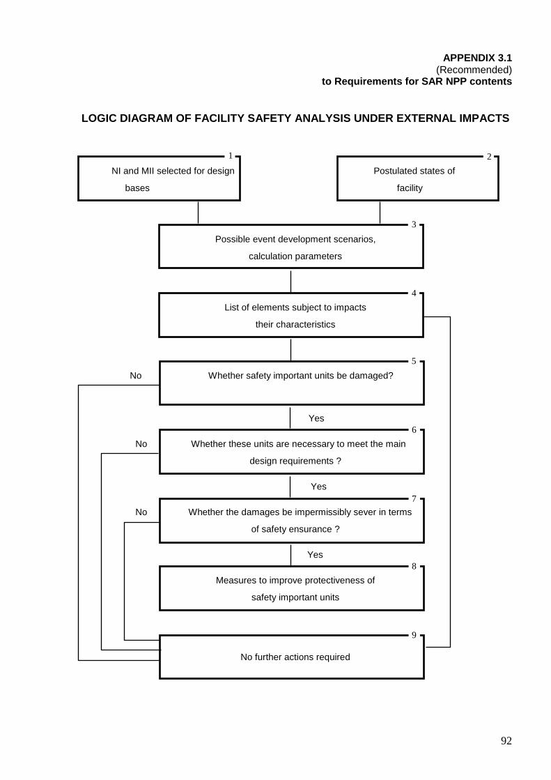
92
APPENDIX 3.1 (Recommended)
to Requirements for SAR NPP contents LOGIC DIAGRAM OF FACILITY SAFETY ANALYSIS UNDER EXT ERNAL IMPACTS
NI and MII selected for design Postulated states of bases facility
Possible event development scenarios,
calculation parameters
List of elements subject to impacts
their characteristics
No Whether safety important units be damaged?
Yes
No Whether these units are necessary to meet the main
design requirements ?
Yes
No Whether the damages be impermissibly sever in terms
of safety ensurance ?
Yes
Measures to improve protectiveness of
safety important units
No further actions required
1 2
3
4
5
6
7
8
9

93
A brief description of NRHF safety analysis under external natural and man-induced impacts:
1. The postulated states of the facility are determined (Box 2).
2. The types of external impacts taken account of in the design bases (Box 1) and their input parameters (Box 3) are determined.
3. A list of affected elements is generated and their characteristics and resistance limits are determined on the basis of probable scenario considerations (Box 4).
4. The response of NRHF buildings, structures, systems and elements to NI and MII is determined. It is done deterministically employing (or not employing) probabilistic analysis elements (Box 5).
5. Safety analysis is performed aiming at risk assessment (Boxes 6 and 7). If unacceptable risk characteristics are obtained for the preset impact levels (para 2.2.1), the protection from NI and MII is implemented.
6. After the protective measures are taken it is necessary to repeat the analysis steps as in Boxes 4, 5, 6 and 7 to verify sufficiency and compatibility of the protective measures.
Note: In some cases the detail consideration may avoid the events for which it is possible to demonstrate that the loads they cause are overlapped with the loads caused by other events under consideration (for example, in the majority of cases it is not necessary to take account of vibration of equipment resulted from external explosions if such equipment designed to withstand loads caused by earthquakes and aircraft crash).

94
APPENDIX 3.2 to Requirements for SAR NPP contents
RESULTS OF CONSIDERING AND ANALYSIS OF NATURAL AND MAN
INDUCED INITIATING EVENT SCENARIOS AT NPP SITE N
Initiating event
Primary impact
Secondary impact
List of buildings and structures, systems and elements subject to possible impact
Mark if resistance analysis is
needed
1 2 3 4 5 6 I
1.1
1.2 II
2.1
2.2
III
3.1
External impacts Earthquakes of any nature Etc. Internal impacts caused by on-site accidents Damage to hydrogen receivers Etc. Internal impacts caused by accidents within NPI external regarding the containment Fire in the turbine hall
Base oscillations, foundation deformation Explosion: 1. ASW 2. Projectiles 3. Fire 4. Etc. Fire load
1. Damages to buildings and structures 2. Projectiles 3. Etc. Damages to buildings and structures of: 1. Main Building 2. Turbine hall 3. Communication lines 4. Etc. Explosion: 1. ASW 2. Projectiles
All systems according to seismic stability categories 1. MCC 2. Etc. 1. Containment 2. Pipelines 2.1. Feedwater 2.2. Etc.
Yes* Yes Yes

95
1 2 3 4 5 6
3.2
IV
4.1
Etc. Internal impacts caused by accidents inside the containment Etc.
Explosion: 1. ASW 2. Projectiles
* Note: Mark «Yes» in column 6 if safety important systems are referred to column 5. According to the mark put in column 6 the SAR NPP shall contain the results of quantitative assessment of event probability, system and element impact parameters and conclusions regarding impact resistance of these systems and elements to be presented in corresponding sections and chapters.

96
CHAPTER 4. REACTOR
The Chapter shall present information and results of analysis necessary for safety justification of the RI operation during the whole period of its design lifetime under normal operation, abnormal operational conditions, pre-emergency situations, design basis accidents and beyond design basis accidents. This Chapter shall also provide information required for analysis of abnormal conditions. The results of this analysis are given in Chapter 15.
Information and analysis given in this Chapter shall be based on design data for RI, reactor, core, core components, reactor vessel internals and other systems important to safety, as well as on the R&D results.
4.1. Purpose of the reactor
4.1.1 Purpose and functions
Purpose and functions of the RI shall be indicated.
The information on the regulatory basis of the RI design shall be presented in a form of a list included to an Annex.
It shall be indicated that the reactor plant and its systems are designed as systems of normal operation, important to safety, which components belong to the first, second and third safety classes (a specific class is indicated in the description of the corresponding equipment).
All equipment installed inside the reactor vessel belongs to the Seismic Category 1 and shall be designed to withstand seismic impacts corresponding to SSE.
4.1.2. Design bases
The following information shall be presented:
• On design characteristics of heat generation; • On the used NF; • On characteristics of the design; • On the mode of NF use; • On the NF burnup; • On duration of the RI operation during a year; • On the design service life of the RI; • On reparability and maintainability.
Provisions of RDs (OPB, PBYa RU AS) should not be presented in this Section, as they formulate the mandatory safety requirements rather than the design bases.
4.2. Reactor design
4.2.1. Description of the reactor
Description of the RI shall be presented with references to the corresponding design documents.
It is necessary to present information on the RI and brief information on the building where the RI is installed, RI building protection against external natural and man-induced impacts (given in Section 2) and against events on the NPP site that are external to the RI building.
The description shall clearly define the RI orientation relative to the NPP building, layout and interaction of the described equipment and systems, their influence on each other.
A list of component parts – systems (components) of the RI that perform independent functions shall be given in the description. The following components (systems) shall be included to this list:

97
• The reactor core; • Reactor shutdown system – control rods of the reactor protection system (EPS) (CPS); • CPS (actuators and a drive); • Reactor pressure vessel including reactor vessel internals; • Equipment (system) for the in-core handling of core assemblies; • Other systems and components (for example, special purpose channels).
4.2.1.1. Reactor core
4.2.1.1.1. Purpose and design bases
It is required to describe the purpose and design bases of the reactor core and its assemblies, to indicate their groups according to safety and seismic stability classification, to present a list of RD defining design criteria and safety principles, general requirements for the reactor core layout and design of its assemblies.
4.2.1.1.2. Description of the reactor core layout
Description of the core layout and design of its assemblies shall be given. Drawings of their general views shall be presented that show positional relationship, main geometric dimensions, anchoring techniques and orientation regarding the reactor axes. Coolant flow diagrams showing coolant distribution over the core assemblies shall be given.
Core maps for the first core loading, transient charges and steady state reactor operation shall be presented. The information on NF inventory shall be presented as well. A reference to the corresponding drawing from the register of the detail design of the core and its assemblies shall be given for each drawing presented herein.
A description of the core and its assemblies shall be accompanied by a list of their main technical characteristics (specifications).
4.2.1.1.3. Materials, NF, coolant
A justification of the selected materials of the reactor core assemblies and description of the NF and coolant shall be given. At that the following information shall be presented:
1. For structural materials:
• On mechanical and thermal and physical (heat transfer) properties depending on irradiation dose and temperature (yield stress, ultimate strength, residual ductility, heat conduction, heat capacity, etc.);
• On strength and thermal creep depending on irradiation dose, temperature, load, duration of NF irradiation;
• On corrosion related interaction with fission products and coolant depending on NF burnup, temperature and duration of NF irradiation;
• On cyclic strength depending on irradiation dose, temperature, load and number of cycles.
2. For welding.
The following information shall be presented:
• On the types of the used welding with a list of RDs that regulate requirements to welding;
• On experience of the welded joints performance or on their tests under similar conditions;
• On differences of mechanical and corrosion properties of welded joints in comparison with the base material under normal operation conditions, operational events and accidents.
3. For nuclear fuel:

98
• On chemical composition, enrichment, density, core charge, non-uniformity of density distribution and fissile isotopes, techniques of their monitoring, qualification of the monitoring techniques;
• On NF creep and swelling depending on temperature, irradiation dose and load; • On mechanical and thermal and physical (heat transfer) properties depending on the
burnup, temperature, content of fissile isotopes (melting temperature, heat capacity, thermal conductivity, thermal expansion, ultimate strength);
• On compatibility with cladding material, mass transfer depending on burnup, temperature, time;
• On a possibility and expediency of SNF reprocessing (brief information).
If new fuel types, including MOX-fuel, are used for the already existing design of RI, the additional data on the results of studies of such fuel behavior in research reactors, etc. shall be presented together with the forecasted estimates of the permissible burnup.
4. For absorbing materials:
• On chemical composition, geometric dimensions, NF enrichment with regard to absorbers, density, monitoring techniques, certification of monitoring techniques;
• On compatibility with cladding materials; • On behavior in a case of accidents (loss of integrity, contact with coolant, temperature
increase); • On behavior under irradiation and change of properties.
If new fuel types, including MOX-fuel with the use of AR with the increased content of 10B nuclide, are used for the existing design of the RI, the R&D results justifying AR behavior under irradiation and forecasted estimates for the permissible burnup of nuclides-absorbers shall be presented.
5. For coolant:
• On thermal and physical (heat transfer) properties; • On acceptable impurities.
4.2.2. Control and monitoring
It is required to present and justify a list of monitored parameters of the core and its assemblies, frequency of measurements, a range of parameter’s measurements, permissible errors of measurements, composition and positions of detectors.
The following information on the monitoring of the core state and control of the RI power shall be presented:
• Protective features and interlocks, controllers, diagnostic systems, automatic control programs;
• For reactivity control – a system of absorber rods – control rods of EPS (CPS) and WPS (Warning Protection System) that represent independent systems;
• For neutron flux measurement – the neutron monitoring system that is a system of normal operation but is designed and manufactured according to requirements to CSS due to its importance to safety;
• For repositioning of control rods – the drive control system (a part of CPS). This system is described in para 4.2.5 of Section 4 (the description can be presented in Section 7);
• In-core instrumentation system; • System for diagnostics of the condition of a safety barrier – fuel element cladding (if such
a system is provided); • RI power control and limiting system;

99
• A system of command generation for warning protection features and interlocks (in CSS sub-section of Sections 7 or 12, if these commands are generated in the EPS CSS);
• A system of RD scram command’ generation - EPS CSS (is presented in Section 12).
If new types of fuel, including MOX-fuel, are used for the already existing RI design, the justification of applicability of the existing metrology support (measurement provision) shall be provided, otherwise a description of the updated metrology support justified in the design, as well as an updated list and permissible values of the monitored parameters and requirements for the instrumentation used during tests shall be presented.
If new types of fuel, including MOX-fuel, are used for the already existing RI design, and power density non-uniformity increases in comparison with the original design, it is required to present a justification of the positions of additional control measurement points for increasing accuracy of the in-core measurements and justification of the improved procedure for the calculated restoration of power density field (including fuel element power density distribution).
If necessary, administrative and technical measures on ICMS (In-Core Monitoring System) upgrade, including ICMS applied software, shall be presented.
4.2.3. Tests and inspections
Programs and procedures for tests of the core and its assemblies, non-destructive inspection and testing techniques verifying design characteristics of the core assemblies shall be described. A list of RDs defining requirements for the scope and methods of inspections and tests shall be presented. It is required to present programs of the incoming acceptance tests of the core assemblies carried out at the NPP, IAC acceptance record, a list of nuclear hazardous operations with the core and its assemblies.
Technical means and inspection methods that are used for monitoring of fuel rod cladding integrity and stipulated for by the design shall be described. They shall ensure reliable and timely detection of faulty fuel rods, including those made of MOX-fuel, for the reactor being under operation or shutdown. Techniques used for inspection of fuel element cladding integrity for the reactor being under operation or shutdown shall be presented and justified.
4.2.4. Analysis of the design
4.2.4.1. Normal operation
Performance of the core and its assemblies shall be described for normal operation of the RI, including power increase to the MCL, transients during scheduled start-ups and shutdowns.
It is required to show the core state under these modes, its interaction with other reactor systems during performance of these functions.
4.2.4.2. Safe operation limits and conditions
Safe operation limits of the core components shall be provided. It is required to refer to the RI design documents and the SAR NPP sections where these limits are justified.
The following shall be presented:
• Limit regarding fuel (temperature or absence of melting); • Limits regarding fuel rod cladding (temperature and density); • Limits regarding the core (reactivity, if it is specified by the RI designer, and power
change period). A limit regarding the thermal power shall be presented for the core (fuel rod cladding temperature limit or fuel temperature limit can be reached in operation at this level of power during design basis accident transient).
The EPS actuation shall be ensured while reaching safe operation limits. Values of settings shall be given. It shall be shown that there is a sufficient margin between the settings and the limiting value.

100
The safe operation limits regarding the reactor core state shall be presented: with regard to the fuel rod specific load, coolant activity, power-flow rate ratio and other limits prescribed by the RI design.
If new types of fuel, including MOX-fuel, are used for the already existing RI design, the appropriate safe operation limits and conditions, including those regarding the fuel rod failure (damage), shall be presented. Additional measures shall be taken to maintain a ratio between fission product activity of the primary circuit coolant and number of damaged fuel elements at the level prescribed by the design. Applicability of the existing settings for actuation of protections shall be confirmed or the application of new settings shall be justified.
4.2.4.3. Nuclear hazardous operations
Nuclear hazardous operations shall be listed that are carried out during in-pile core assembly handling and a complete core unloading, if such an activity is stipulated for by the design.
If new types of fuel, including MOX-fuel, are used for the already existing RI design, additional measures on handling of fuel assemblies manufactured with the use of such fuel shall be presented.
4.2.4.4. Justification of the design
The information on activities carried out to justify design of the reactor core and its assemblies shall be presented. This information should be grouped as follows:
• Neutronics justification (is given in para 4.2.7); • Justification of thermal-hydraulic characteristics (see para 4.2.8); • Strength justification.
The information on R&D performed to justify the reactor core design shall be presented according to the following sequence:
• A list of experiments, R&D including those carried out at test benches, research reactors and NPPs;
• Description of experimental techniques; • Analysis of experimental results.
If new types of fuel, including MOX-fuel, are used for the already existing RI design, a scope of additional test bench and reactor experiments stipulated for by the design and carried out to justify safety of new core charges with the use of such fuel shall be presented.
4.2.4.5. Performance in a case of failures
It is required to present a list of IE and RI failure analysis including human errors, and give an assessment of their impact to the reactor performance and safety.
While considering failures, it is required to analyze common cause failures and give a qualitative (if necessary) and quantitative assessment of their consequences.
It is required to analyze effects of these failures on performance of the reactor and other RI systems. A list of systems and equipment necessary for limitation (mitigation) and/or elimination of consequences of such failures shall be provided.
A list of all design basis accidents shall be presented in this Section (reference to Section 15 is possible). Beyond design basis accidents considered in the design shall be also listed (also with reference to Section 15).
If new types of fuel, including MOX-fuel, are used for the already existing RI design, the corrected list of IE justified in the design, failure analysis and analysis of design basis accidents and beyond design basis accidents considered in the design shall be presented. The results of these analyses shall be given in Chapter 15.

101
4.2.5. Reactor shutdown system - CPS rods
4.2.5.1. Purpose and functions of the system
It is required to present a classification of CPS rods according to their functions (SPS), safety classes and seismic stability category of components, and respective codes of their classification.
The information on the regulatory basis of the design of the reactor shutdown system shall be presented.
4.2.5.2. Design bases
Information on the design bases (efficiency and response time) shall be provided for normal operation and accidents.
4.2.5.3. Description of the CPS rod design
The CPS rod design shall be described with indication of the purposes of the main elements. The information on the CPS rod groups shall be presented.
It is required to describe the design and purpose of the CPS rod guiding channels - CPS guide tubes, to present drawings of the CPS rods with the main geometrical dimensions and rod positioning regarding the reactor core.
Performance of the CPS rods shall be justified by the experience of their performance in other reactors and results of bench tests.
The main design characteristics of the rods shall be provided.
4.2.5.4. Materials
The information given in para 4.2.1.1 shall be used. The information on the references which confirm performance of the CPS rod materials and CPS guide tubes shall be given.
4.2.5.5. Quality assurance
Information on the NPP QAP for the rod fabrication shall be provided.
4.2.5.6. Tests and inspections
It is required to present and justify frequency of inspections and a list of the inspected parameters of the CPS rods that are used for determining the performance degrading criteria (decrease of physics effectiveness below the specified level, absence of rod displacement).
A list of R&D carried out to justify the design and performance of the CPS rods shall be presented, including those for manufacturing and physical weighting of prototypes, manufacture and hydraulic tests of prototypes.
4.2.5.7. Control and monitoring
Information presented in para 4.2.2 shall be used.
4.2.5.8. Safe operation limits and conditions
The reactor safe operation limits and conditions shall be presented with regard to the state of the CPS rod system (response and efficiency characteristics, permissible axial offsets, service life, and frequency of tests).
4.2.5.9. Analysis of the design
4.2.5.9.1. Performance under normal operation

102
Performance of the CPS rods shall be described for RI normal operation, pre-emergencies and design basis accidents. The state of the CPS rods under these modes shall be presented. It is required to demonstrate what affects and provides for their performance.
4.2.5.9.2. Performance in a case of failures
Possible failures and damages of the CPS rods shall be analyzed with qualitative and/or quantitative assessment of their consequences.
The data on measures accepted for the design of the CPS rods and guiding channels and for their operation and aimed at exclusion of the failures or limitation of their consequences shall be presented. Failures of equipment during CPS rod loading and unloading, refueling, failure to withdraw from a cell, etc. shall be listed.
Information on justification of safe operation of the reactor shall be presented based on comparing with results of the CPS rod operation of the similar design and results of bench tests and calculations.
4.2.5.9.3. Justification of the design
Information on activities done to justify CPS rod design shall be presented:
• Justification of thermal and hydraulic characteristics; • Justification of operability (strength and reliability).
Information on the each group of activities shall consist of two parts – calculations and experiments. The part of calculations shall include:
• A list of calculations; • A list of methods and computer codes used with data on their qualification; • Results of calculations and their analysis.
The part of experiments shall include:
• A list of R&D carried out; • Description of the applied techniques; • Analysis of the experiment’s results.
In this connection the following shall be presented:
• Design value of CPS rod worth with regard to the corresponding charge of absorbers; reduction of worth; burnup; fluence on AR and CPS rods during the prescribed service life;
• Main thermal and hydraulic characteristics of CPS rods including the coolant flow rate distribution; temperature of absorber, AR cladding, rod and CPS protective tube elements; pressure differential on rods and expulsive force affecting them;
• Main strength characteristics of CPS rods and sleeves determining their reliability, including SDS of CPS rod cladding and elements; changes in AR size and shape due to swelling, creep, temperature, interaction between an AR bundle with protective tube, interaction between CPS rod parts and CPS protective tube;
• Values of the set up lifetime, set up service life and set up shelf life of the CPS rods; • Criteria of the loss of the CPS rod operability.
If new types of fuel, including MOX-fuel, are used for the already existing design the RI, sufficiency of the existing reactor shutdown systems, including those performing EPS function, shall be justified as regards effectiveness and response time. Otherwise the design documentation on the modernized systems and results of their pilot operation shall be presented.
4.2.5.9.4. Evaluation of the design
There shall be an assessment of whether the design meets the RD requirements.

103
4.2.6. Warning emergency protection system
Information presented in para 4.2.5 shall be used.
Paragraph “Control and monitoring” shall provide data regarding positioning of WPS assemblies.
Paragraph “Evaluation of the design” shall demonstrate how the design meets the GSP requirements.
4.2.7. Neutronics calculation of the core
The information and analysis necessary for justification of safe operation of the reactor core during its design service life under normal operation conditions, operational events, pre-emergencies, design and beyond design basis accidents shall be presented, as well as the information necessary to carry out the accident cause analysis, which results are given in Section 15.
The information and analysis presented in this subsection shall be based on the design documentation pertaining to the reactor, the core, and the core assemblies, and on R&D results.
4.2.7.1. General description and basic neutronics characteristics of the core
The following data shall be presented:
• Type of NF; • The core design features: layout, FA gripping techniques, gaps between FA; • Side and edge reflectors, characterization of structures behind the reflectors; • Technique of equalization of power distribution field accepted in the design; • Methods of power control accepted in the design; • CPS rods (EPS) (see para 4.2.2); • Presence of other elements in the reactor core: experimental FA, neutron source, etc.; • Accepted techniques for reloading of the core FA, CPS rods; • A list of the main physical characteristics of the core and their values, NF enrichment,
maximum power density, NF melting temperature margin under nominal conditions, CPS rod worth, maximum reactivity margin, reactivity effects and factors, subcriticality margins after reactor scram, duration of fuel cycle (campaign), maximum fuel burnup, maximum neutron flux, time between refueling, etc.
4.2.7.2. Core operation modes in the course of a campaign
The following shall be presented:
• General approach to arrangements for the refueling of the reactor; • Characteristics of the steady-state refueling mode; • A list of the main design states of the reactor core under the steady-state mode; • Main characteristics of programs for reloading of the core FA and CPS rods; • General characterization of a transient; • General characterization of the start-up core and values of its main physical parameters.
4.2.7.3. Characterization of power density field in the core and adjacent structures
The data on distribution of the power density field in the core and adjacent structures shall be presented for different states of the core that characterize the fuel campaign (before refueling, after refueling, under the average steady state and other states stipulated for by the design) including neutron fluxes in the core and adjacent structures.
104
4.2.7.4. Characterization of the power density field in a case of CPS rod positions that are not specified by the design
The most unfavorable positions of the CPS rods shall be considered. The data on power density field and neutron flux distributions shall be presented for the selected configurations.
4.2.7.5. Reactivity effects and factors related to temperature and power changes
Values of temperature effects and reactivity factors accepted in the design and a structure of these effect constituents shall be presented.
4.2.7.6. Doppler effect
Values of reactivity effects due to changes in the neutron resonance interaction under the change of temperature (Doppler-effect) shall be presented. The Doppler-effect values shall be given for different states of the core over the campaign and for each core component with regard to the basic core materials and different isotopic inventory of fresh fuel.
4.2.7.7. Asymptotic values of temperature and power effects of reactivity for different states of the core
Values of temperature effect of reactivity and its constituents for different states regarding the fuel burnup: temperature values of the elements of the core at nominal power, as well as values of power effect of reactivity and its constituents for different states of the core regarding the fuel burnup shall be presented.
4.2.7.8. Reactivity balance and control efficiency
There shall be an analysis of reactivity balance and compliance of the reactivity characteristics with requirements of PBYa RU AS. The reactivity balance shall be built with accounting of possible errors in determining the reactivity effects. The core reactivity balance shall be determined for the start and end of the campaign and for intermediate burnup values, if necessary. The following factors affecting reactivity and depending on different operating states shall be taken into account:
• AR CPS control groups, their prospective and minimum permissible worth; • Effectiveness of the burning absorber; • Concentration and effectiveness of the boric solution; • Disturbances of absorber and fuel temperature and possible bubble disturbances; • Burnup (slag); • Xenon and samarium poisoning; • Permissible heights of rod insertion to the core and permissible value of their
mismatch.
Minimal required and predicted subcriticality margin of the scrammed reactor shall be presented and discussed for different moments of the campaign taking into account uncertainty in determination of this margin and experimental tests carried out at the existing reactors.
Methods and limitations of control under normal operation shall be described in full scope. The following aspects shall be described:
• Concentration of liquid absorber and its changes; • Movement of control rods including those affecting axial profile of power density; • Possible changes in the coolant temperature and flow rate.
The following shall be described:
• Start-up from the cold and hot state and from the state with the maximum xenon poisoning;
• Load following mode and compensation of the unsteady xenon poisoning; • Affects on tree-dimensional distributions of power density (redistribution of xenon and
xenon oscillations);
105
• Possible effect on burnup distribution.
If new types of fuel, including MOX-fuel, are used for the already existing RI design, applicability of the existing system of boron supply to the primary circuit shall be justified or design documentation on modernization of this system shall be provided.
4.2.7.9. Analysis of the reactor subcritical state during refueling. Neutron source, location and sensitivity of neutron detectors, subcriticality monitoring The following shall be presented:
• A general approach to the monitoring of the reactor subcritical state; • Neutron source, its design and main characteristics; • Neutron background of the core depending on the isotope composition of the fuel and
degree of its burnup; • Location and sensitivity characteristics of neutron detectors; • Requirements to the monitoring of refueling and compliance of the considered design
with those requirements.
4.2.7.10. Power monitoring
There shall be a brief description of the neutron detectors in use and their characteristics as regards the measuring the reactor power. It is required to analyze to what degree the capabilities of the system selected for measuring power comply with the requirements of PBYa RU AS and an analysis of capabilities of the power measurement system to monitor the power density field distortion resulted from positioning of control rods that is not stipulated for by the design and due to other causes.
4.2.7.11. Methods, codes and constants used in physical calculations
It is required to present a brief description of codes and constants used in the physical calculations. The certified codes shall be listed. It is required to indicate a degree of readiness of other codes for their certification, availability of the verification reports, user manuals and other documentation.
4.2.7.12. Basic results of experimental studies of reactor physics carried out at critical test benches, research and operating power reactors
There shall be a description of the modeling critical benches and a list of experiments carries out at these benches as well as at research and operating power reactors. The main results of the calculation analysis of these experiments and translation of these results for assessment of an error in physical characteristics of the reactor design shall be presented.
If new types of fuel, including MOX-fuel, are used for the already existing RI design, information on all neutronics characteristics of the reactor core stipulated for by para 4.2.7 shall be presented.
4.2.8. Thermal-hydraulic calculation
4.2.8.1. Design constraints
The information on design constraints affecting thermal-hydraulic characteristics, RI design modes and selection of its parameters shall be presented. A list of parameters shall include:
• Maximum fuel rod cladding temperature; • Maximum coolant temperature; • Rate of coolant temperature changing; • Maximum linear load of fuel rods; • Maximum coolant flow rate in the core; • MCP cavitation margin.

106
4.2.8.2. Thermal-hydraulic calculation of the core
The following shall be presented:
1. Distribution of coolant flow rate and linear power density.
The following shall be described:
• A scheme of core throttling zones; • Distribution of coolant flow rate over the throttling zones, through the gaps between fuel
assemblies and for reactor vessel cooling; • Average and maximum values of linear power density for different enrichment zones and
throttling zones as of the beginning and end of the fuel cycle (campaign); • Coolant temperature at the core outlet and the reactor outlet temperature with
accounting of coolant flow rate distribution as of the beginning and end of the campaign; • fuel rod cladding temperature at the outlet of throttling zones taking into account possible
non-uniformities in temperature distribution.
2. Pressure differential in the core and hydraulic resistance
It is required to describe how the coolant flow through the core is arranged at the reactor inlet (for example, high and low pressure headers), provide pressure differential values in the core and corresponding distributions of hydraulic pressure among the core components.
3. Methodologies and computer codes
There shall be information on the methodologies and computer codes used in the thermal-hydraulic calculations of the core, information on their verification or justification of reliability of results obtained through their use.
Information on experiments performed to justify the methodologies and computer codes in use shall be presented.
The data on accuracy of the obtained results of thermal-hydraulic calculations shall be presented.
4.2.8.3. Thermal-hydraulic calculation of the RI
This section shall describe the thermal-hydraulic calculations of the RI primary circuit and emergency heat removal system.
The description shall include the following information:
1. Data on layout of equipment and piping of the RI primary circuit. The RI thermal-hydraulic flow diagram shall be presented:
• A number of coolant circulation circuits and their purposes (normal operation heat removal system, emergency heat removal system);
• Driving force of coolant motion (forced circulation, gravity circulation); • A list of equipment and pipelines in each circulation circuit, design values of coolant flow
rates for each circuit component and pressure differentials regarding the corresponding flow rates;
• Coolant circulation flow diagrams for each circuit, axial positioning of loop elements (equipment, pipelines) of different circuits, their geometric characteristics (including length of coolant circulation in the given element), amount of coolant in each element;
• Values of coolant levels in the RI primary circuit components and pressure of gas medium under the design modes.
2. Design modes of the RI operation
This section shall include:
• A list of design modes (with reference to a corresponding subsection of Section 4);

107
• Thermal-hydraulic features of each design mode; • Coolant parameters and rates of their changes under different design modes; • Distribution of coolant temperature under the design modes.
3. Methodologies and computer codes
The information on methodologies and computer codes used in the RI thermal-hydraulic calculations, data on their verification or justification of reliability of results obtained through their use, data on accuracy of the results of thermal-hydraulic calculations shall be presented.
4.2.8.4. Tests and inspections
Test and inspection programs and methodologies, which must be used to confirm the design thermal-hydraulic characteristics of the core and RI circulation circuits shall be described.
4.2.9. CPS actuators
The content of the Section shall be based on the design documentation developed for CPS actuators, CPS actuator-related RD requirements, developed QAP, operation experience gained at prototype products, tests of leading products fabricated in the course of R&D; it shall correspond with the sequence given below.
4.2.9.1. Purpose and design bases
It is necessary to present the following:
• Information on a composition, purpose and functions of the actuators; • actuators safety and seismic stability classification; • actuators criteria, principles and design limits for normal operation, operational events
and design basis accidents; • Permissible limiting values of main mechanical, strength characteristics and permissible
values of actuators reliability.
4.2.9.2. Description of the design
The following shall be presented:
• A description of the actuators design indicating individual devices (elements), which perform designated functions including devices for monitoring, anchoring and sealing;
• Sufficiently detailed drawings and schematic views illustrating the design, kinematics and locations of the actuators;
• Main technical characteristics (specifications) of actuators; • A list of systems and equipment affecting actuators performance.
4.2.9.3. Materials
There shall be information on grades and properties of steels and structural materials the actuators are made of, and a justification of their operability during the required period of time in the water medium under design temperatures and radiation impacts corresponding to the normal operation conditions of RI, operational events and design basis accidents.
4.2.9.4. Quality assurance
References to QAP for development (design), manufacture, acceptance and assembling of actuators shall be given. Basic requirements of these programs and RDs establishing requirements to quality assurance of the actuators and their components shall be listed.
2.9.5. Control, monitoring and testing
The following shall be presented:
108
• Principles of actuators control and monitoring of their state; • Characteristics of the actuators controlling signals; • Analysis of possible controlling effects to the actuators by automation and personnel; • Techniques, means, scope and frequency of inspection of state and testing of the
actuators to ensure their operability during operation and their compliance with the regulatory requirements;
• Information on the commissioning operations with the actuators including the list of their test programs, which demonstrate that the pre-start-up tests are sufficient to justify the RI safety, as well as the list of measures to prevent accidents during the testing.
4.2.9.6. Analysis of the design
4.2.9.6.1. Performance under normal operation conditions
The following shall be presented:
• A description of the actuators functioning during normal operation of RI including transients in case of scheduled start-ups, power changes and shutdowns;
• A description of the actuators state, their interaction in the course of performing the designated functions;
• Safety and reliability requirements set forth to the safety important systems and equipment that interact with the actuators;
• A description of the actuators’ performance in a case of equipment systems failures and characterization of the design measures to ensure the actuators functioning in a case of these failures.
4.2.9.6.2. Performance under failures
The following shall be presented:
• Analysis of the actuators failures including failures due to personnel errors; • A description and justification of sufficiency of measures to prevent the actuators
common cause failures including external and internal impacts and failures of systems and equipment;
• Qualitative and quantitative (as necessary) assessment of failure consequences including characterization of changes in the main RI parameters that affect safety;
• A list of actuators failures, which are the initiating events for operational events and design basis accidents and require an additional analysis in the corresponding section of the RI safety analysis.
4.2.9.6.3. Justification of the design
It is necessary to demonstrate that the actuators comply with the safety RDs, tested in the course of the VVER reactors’ operation or are tested under conditions similar to the required ones and are justified by R&D results.
4.2.9.6.4. Evaluation of the design
It is necessary to present an assessment of whether the actuators design complies with the RD requirements.
4.2.10. Reactor pressure vessel
4.2.10.1. Purpose and design bases
The following shall be presented:
• Information on the purpose and functions of RI pressure vessel; • RI pressure vessel classification regarding safety importance and seismic stability;

109
• The regulatory basis for the design; • Criteria, principles and design limits laid as the basis of the RI pressure vessel design
regarding normal operation, operational events and design basis accidents; • A list of RI pressure vessel failures considered in the NPP safety analysis.
4.2.10.2. Description of the design
The following shall be presented:
• A description of the RI pressure vessel design identifying individual components performing designated functions including devices for control, anchoring, sealing;
• Drawings and flow diagrams illustrating the design; • Main technical characteristics (specifications) of the RI pressure vessel.
4.2.10.3. Materials
There shall be a list of RDs establishing requirements to the structural materials used and information on grades and properties of steels of the RI pressure vessel; justification of their performance during the RI service life in the water medium under design temperatures; temperature changes and radiation impacts corresponding to the normal operation conditions of RI, operational events and design basis accidents.
4.2.10.4. Control and monitoring
The following shall be presented:
• Techniques, means, scope and frequency of RI pressure vessel metal inspections to ensure its performance during operation and their compliance with the regulatory requirements;
• SDS study results regarding the pressure vessel material during commissioning operations at the RI.
4.2.10.5. Tests, inspections and monitoring of metal conditions
The following information shall be presented:
• On tests of semi-manufactured items of the RI pressure vessel in the course of manufacturing;
• On acceptance control of conditions of the RI pressure vessel or its component parts before assembling;
• On inspections during assembling; • On stress, leaktightness and stability tests after completion of the assembling.
4.2.10.6. Analysis of the design
4.2.10.6.1. Performance under normal operation conditions
The following shall be presented:
• A description of the RI pressure vessel functioning during normal operation under all modes stipulated for by the operation regulations for any combinations of loads (thermal, cyclic, seismic, shock, vibration, radiation, corrosion, etc.);
• An analysis of possible failures of the RI pressure vessel components with an assessment of their consequences done on the basis of PSA;
• Compliance of the RI pressure vessel with applied requirements regarding mechanical, strength and reliability characteristics under all modes of its performance.
4.2.10.6.2. Performance under failures
The following shall be presented:
• An analysis of failures of the RI pressure vessel or its components;

110
• A list of the RI pressure vessel failures, which are the initiating events for operational events, design and beyond design basis accidents and require an additional analysis to be presented in the corresponding section, which deals with the RI safety analysis.
4.2.10.6.3. Justification of the design
It shall be demonstrated that the RI pressure vessel meets the regulatory requirements, that the main technical solutions were used along with the experience gained in the course of manufacturing, assembling, testing and operation of pressure vessels of similar facilities, and the design is justified by documents or reports issued during R&D.
4.2.10.6.4. Safe operation limits
The following limits shall be given for the RI pressure vessel:
• Pressure limit; • Temperature limit; • Irradiation limit; • Strength limit.
4.2.10.6.5. Maintenance and reparability
The information on maintenance and repair of the RI pressure vessel shall be presented together with a brief description of the repair technology.
4.2.10.6.6. Reliability analysis of the RI pressure vessel
The information on the reliability analysis and the design value of failure probability of the RI pressure vessel shall be presented.
Distributions of neutron flux and fluence on the core boundaries and on the pressure vessel walls shall be presented for different instances of the reactor service life.
If new types of fuel, including MOX-fuel, are used for the already existing design of the RI, an additional justification of the radiation resistance of the reactor pressure vessel shall be provided, and limits on fast neutron fluence to the reactor pressure vessel shall be formulated.
4.2.10.6.7. Control and monitoring
It is necessary to use information given in para 4.2.2.
A list of points of monitoring and information on the diagnostic systems shall be presented.
4.2.10.6.8. Evaluation of the design
Assessment of the RI pressure vessel compliance with regulatory criteria and safety principles and validity of the design solutions making shall be presented.

111
CHAPTER 5. PRIMARY CIRCUIT AND RELATED SYSTEMS
The scope of Chapter 5 covers the safety aspect of the primary circuit functioning and maintaining its integrity in normal operation, operational events, emergencies and after postulated initiating events which do not involve the loss of integrity of the primary circuit. The leaktight primary circuit represents the barrier that follows the fuel rod cladding, which limits propagation of RadS resulted from accidents.
The information shall assure that the safety analyses’ results incorporated in SAR NPP are correct, sufficiently complete and all required safety analyses done.
There shall be references to the information included in other chapters, if such information is related to the primary circuit.
There shall be a list of applicable detail design documentation, which served as the basis for compilation of this Chapter, and the text shall refer to the corresponding documents.
The Chapter shall contain information on the primary components and related systems.
The primary circuit represents a set of equipment and its connecting pipelines along with the pressurizer system where the coolant circulates through the core under working pressure.
The primary circuit and related systems provide for heat removal by the coolant from the reactor core in normal operation, operational events, emergencies and design basis accidents.
The Chapter shall consider the following components and systems incorporated in the primary circuit:
1. Main Circulation Circuit (MCC).
MCC transfers heat from the reactor to SG and normally includes:
• reactor pressure vessel with upper part and seal; • MCP; • SG; • MCC pipelines (pipelines connecting the above listed components).
2. Systems (or their parts) linked to MCC within the primary circuit pressure boundaries.
2.1. Systems which provide for normal functioning of MCC:
• pressurizer (pressure maintaining system); • emergency reactor cooling; • coolant clean-up.
2.2. Auxiliary systems:
• primary circuit make-up and blowdown; • drains and air drain valves, filling lines; • pressure instrumentation leads and sampling lines.
3. Primary circuit valves
4. Anchoring units
Since at different NPP types the number of the primary circuit components and related systems may differ, the Applicant shall determine the complete set of these components and systems depending on the design features.
The primary circuit boundary incorporates the first passive barrier, eg. a pipe wall (including SG on the primary coolant side) and the second cut-off valves on the core side at any linked MCC pipeline, which contains the coolant and may be subjected to the primary pressure..
112
The dividing elements (supports, shock absorbers, displacement constraints, etc.) between the primary circuit components and structures (foundations) shall be considered as constituents of each system they pertain (see annexes).
5.1. Brief description
The Section shall include a brief description of the set of systems for heat removal and transfer from the core to SG.
5.1.1. Primary circuit and related systems
The subsection shall summarize information on the design, safety analyses done regarding the primary systems and components.
There shall be a description and purpose of the primary circuit, its main components and related systems. The description shall outline components performing independent functions as well as safety functions of each component and system. There shall be tables of important design and working (operating) characteristics.
The safety criteria and principles considered in the design shall be described.
It shall be demonstrated how the main function of the primary circuit is performed, i.e. heat removal from the core by the sufficient amount of the coolant having appropriate quality, in normal operation, operational events, emergencies and design basis accidents when the design operational limits and safety limits are met including that of fuel damage (Annex 1 PNAE G-1-024-90 PBYa RU AS-89); a list of postulated initiating events shall be given.
References shall be made to other SAR NPP sections, which contain more detailed requirements to individual systems and components of the primary circuit.
It shall be demonstrated that the design provides for monitoring of temperature, pressure and chemical composition of the coolant in the primary circuit in normal operation, operational events, emergencies and design basis accidents.
It is required to demonstrate that all primary systems and components were designed considering that they withstand during their whole service life the environs’ conditions (pressure, temperature, humidity, radiation), which arise during normal operation, operational events, emergencies and design basis accidents and after them.
It is required to describe all seismic load-responding elements installed at pipelines and it shall be demonstrated that a failure of systems and components that do not pertain to Seismic Stability Category 1 will not result in a failure in the systems and component pertaining to Seismic Stability Category 1.
It shall be indicated that the design provides for the operator to obtain information on:
• violations of normal operation conditions in the primary circuit; • the working parameters having approached the operational limits and/or safe operation
limits.
The possibility shall be demonstrated to drain the radioactive coolant and presence/absence of stagnant zones (para 2.1.5 PNAE G-7-008-89), as well as the possibility to fill the system with water and evacuate air (para 2.1.6 PNAE G-008-89). It shall be confirmed that the outer surfaces of the equipment and piping with the wall temperature over 45°С are provided with thermal insulation (para 2.1.9 PNAE G-7-008-89). It is required to demonstrate that the primary circuit is designed so that its equipment is accessible for inspections, maintenance and repair and that the personnel exposure doses are maintained as low as reasonably achievable that does not exceed the design limits.
The references shall be made to design documentation of the primary systems and components.

113
The information shall be presented regarding calculations done; there shall be a list experiments and analysis of their results.
5.1.2. Flow diagram
The primary circuit flow diagram shall be presented with indication of the primary circuit boundaries and all main components, working pressure, temperatures, coolant flow rate and amount for the stationary operational mode of full power operation of the installation. The flow diagram shall show all systems connected to the primary circuit and their disconnection mechanism; this is of special importance for the systems containing non-radioactive media and systems under pressure which is less than that of the primary circuit.
The pipeline layout within the reactor building shall be presented as an isometric view.
5.1.3. Instrumentation and control block-diagram
The instrumentation and control block-diagram of the primary circuit and systems, which are permanently connected to it and are under primary circuit pressure, shall be presented. It shall be shown what I&C are used to measure pressure, temperature, flow rate, chemical composition of water and gas and to monitor displacements and integrity. The instrumentation accuracy class shall be indicated.
5.1.4. General view drawings
The general view drawings shall be presented. They shall show elevations of the equipment and sizes of the primary circuit regarding the supporting and surrounding concrete structures. They shall also demonstrate that accessibility for maintenance and inspections is provided for as well as that the requirements of para 2.5.4 PBYa RU AS-89 are met as regards arrangements for gravity circulation. If the design provides for a biological shielding, it shall be indicated.
5.2. Integrity (strength and leaktightness) of the primary circuit pressure boundaries
The section shall contain a justification of the design measures to ensure strength and leaktightness of the primary equipment and piping.
It shall be demonstrated that all equipment and piping withstand without collapse all static and dynamic loads (para 4.3 OPB-88 and paras. 2.5.2 and 2.5.3 PBYa RU AS-89).
5.2.1. Compliance with standards and rules
5.2.1.1. Compliance with applicable safety RTD
A table shall be presented to demonstrate compliance with the applicable PNAE requirements, which is overseen by Gosatomnadzor of Russia. In cases where the requirements are in place, which, if met, can result in unjustified complications and difficulties, which are not compensated for by improvement of quality and safety level, there shall be grounds to meet alternative requirements. It shall be described how the acceptable safety and quality level is to be achieved when the alternative requirements are proposed.
114
5.2.1.2. Applicable provisions of standards
In cases where the provisions of Standards allow the developer to select an option of the standard application (for example, combination of main loads with that of the earthquake), the options in use shall be indicated along with necessary justifications.
5.2.2. Primary circuit overpressure protection
There shall be a list of components performing overpressure protection function for the primary circuit. There shall be a brief description of PORV installed at the pipeline for steam dump to the bubbler and designed to protect the primary equipment and piping from exceeding the primary coolant limiting pressure in accident and transient modes (para 2.1.7 PNAE G-7-008- 89).
The subsection shall list all measures and ways of protection of the primary circuit systems from pressure increase over the design limits in normal operation, operational events, emergencies and beyond basis accidents.
There shall be total efficiency of devices and SV designed to dump steam from the primary circuit and the measures, which minimize coolant losses in case valve stick open.
There shall be references to other SAR NPP chapters, which specifically describe individual systems and components providing for protection of the primary circuit from collapse. The information on individual systems shall be presented following the sequence given in Annex to “General Requirements” Chapter.
5.2.2.1. In addition to the above information, in “Design Bases” Section it shall be demonstrated how the possibility of pipeline break and equipment damages involving breakaway of their parts are minimized.
At this the following shall be presented:
1. Pipeline breakage criteria.
There shall be data on potential locations of pipeline breaks (connection points to the equipment, maximum stressed locations) as well as on areas where there is a potential hazard of damage of the nearby safety important equipment.
For the low temperature mode the shall be the design data confirming that pressure in the primary circuit components under low temperatures (below the working temperature) is limited by the values which exclude brittle failure or pressure corresponds to the stress value which is permitted for the given temperature level.
2. Analysis of consequences of pipeline breakage.
The subsection shall contain the results of analysis of consequences of pipeline breaks, which shall consider the following effects to the adjoin equipment:
• temperature; • pressure effects; • water and steam jet loads on the adjoin equipment and pipelines; • humidity and radiation impacts; • reactive loads resulting in the damage pipe whipping; • damages caused by projectiles; • flooding of the safety important equipment.
When the “leak-before-break” concept is applied, it shall be indicated for which pipelines it is applied and a reference shall be given to the document justifying its application.
3. Protection from pipeline break consequences.
It is required to describe methods used in design for physical separation of pipelines and constraint displacements to prove that:
115
• a rupture of one primary pipeline does not lead to a rupture of another, which is necessary for mitigation of the accident consequences;
• a rupture of the pipeline, which does not pertain to the primary circuit, is not a cause of the loss of coolant accident;
• a rupture of the primary pipeline does not result in collapse of the containment; • a release of the coolant does not hinder operations at the control posts and does not
interfere with functioning of the systems required for elimination of the accident consequences.
5.2.2.2. In addition to the above information, in “Design of the System” Section it is required to present results of analyses of transients which may be accompanied by pressure increase in the primary and secondary circuits. The design mode involving maximum increase in pressure shall be described to determine SV capacity.
It is required to describe equipment and mechanisms of the primary circuit overpressure protection systems; provide for general view drawing of safety and relief valves and descriptions of their operation principles.
The important design parameters shall be determined for each component including design, through cross-section area, design flow capacity and installation locations as well as diameter, length and layout of pipelines.
The design parameters shall be listed (for example, pressure and temperature); number and type or operation cycles shall be determined for each component in question; external conditions the systems and components are designed to withstand shall be indicated.
The information on draining devices shall be presented (para 6.2.26 PNAE G-7-008-89).
A detailed description shall be provided for actions and tooling for assembling pressure dumping devices located within the primary circuit boundaries and at SG on the secondary circuit side. The input data shall be determined for calculation of permissible loads on components (axial force, bending and twisting). A list of these loads and resulting stresses shall be presented.
There shall be information on adjustment inspection of the safety valves, pressure locks, if used (paras. 6.2.28 - 6.2.30), as well as on their locations and maintenance (para 6.2.25 PNAE G-7-008-89).
There shall be an analysis of thermal-hydraulic calculation of the primary circuit overpressure protection system and the system’s capabilities to perform designated functions.
The analysis results shall be presented to demonstrate how changes of operational modes, in parameters and operating characteristics of the equipment affect the system characteristics. There shall be a design justification of the flow capacity and number of valves, and methods of checking and inspecting their functioning (para 6.2 PNAE G-7-008-89) as well as the system reliability analysis.
5.2.2.3. In addition to the above information, in Section “System Functioning Monitoring and Control” it is required to present flow diagrams of pipelines and block-diagrams of instrumentation and controls (paras. 6.3.5, 6.3.6, 6.3.9 PNAE G-7-008-89) pertaining to the primary circuit overpressure protection systems, which show the number (para 6.2.2 PNAE G-7-008-89) and locations of units and mechanisms including valves, pipelines, vessels, I&C and actuators. The boundaries with other systems shall be indicated.
There shall be information on functioning tests of the safety valves including controls before the first start-up and re-starts (para 6.2.27 PNAE G-7-008-89).
5.2.2.4. In addition to the above information, “Tests and Inspections” Section shall contain the tests and inspections to be carried out before the operation starts, during the installation start-up to verify functional characteristics and during operation to check and confirm reliability.
116
5.2.3. Primary circuit materials
The subsection shall contain the data confirming that the materials, manufacturing and inspection techniques for components of the primary circuit pressure zone meet the requirements of NPP Rules, PNAE G-7-002-86 “Standards for Strength Calculations”, PNAE G-7-009-89 "Basic Provisions. Welding and Overlaying”, PNAE G-7-010-89 "Welded Joints and Overlays. Rules of Inspection".
5.2.3.1. Specifications for materials
There shall be a list of specifications for ferritic and austenitic stainless steel, non-ferrous metals (if used) which the primary circuit components are made of including anchoring as well as welding and overlaying materials.
In case where the selected material is not listed in Annex 9 to NPP Rules or listed but used with deviations regarding application conditions set forth in Section 3.4 of NPP Rules a reference shall be given to documents justifying the possibility of use of the selected material. The list of documents is given in Section 3.4 of NPP Rules.
It is required to demonstrate how the properties of the primary circuit material, which significantly affect the pressure boundary integrity, are considered in the course of the material selection:
• chemical compatibility with coolant; • compatibility with the material of components contacting with the pressure circuit (thermal
insulation, supports, sealing elements, etc.); • cyclic and long-term strength and creep; • corrosion (including stress-corrosion), cyclic corrosion and erosion characteristics; • radiation damage (for steel exposed by neutron radiation); • crack resistance; • brittle failure resistance; • processiblity; • activation under irradiation; • behavior under accidents.
The data shall be presented on inspection of components which unfavorably affect operational characteristics of materials as well as on measures to limit such admixtures (for example, cobalt content in nickel-containing steel; copper, nickel and phosphorus in the RPV steel; carbon, sulfur and silicon in carbon steel, etc.).
5.2.3.2. Compatibility of structural materials with primary coolant
The following information about compatibility of the primary coolant and structural materials and outer insulation of the pressure zone shall be presented.
1. Chemical composition of the primary coolant with a reference to the corresponding regulatory documentation.
Herein, indicate changes in chemical composition in different modes if additives are used (for example, absorber); limiting permissible content of chlorides, fluoride compositions, oxygen, hydrogen and solvable corrosion products.
2. Compatibility of structural materials with the primary coolant.
Herein, present a list of structural materials contacting with the primary coolant and describe compatibility of the materials and the coolant, admixtures and radiolysis products which they can contact. If non-metallic materials are in contact with the primary coolant, there shall be a description of their compatibility with the coolant.
3. Compatibility of structural materials with the outer insulation of the primary circuit.
Herein, list structural materials of the primary circuit having insulation and describe their compatibility with the outer insulation especially in case of coolant leaks. There shall be

117
information on non-metallic insulation of austenitic stainless steel, which is to indicate whether the concentration of chlorides, fluoride compounds, sodium and silicates in the insulation remains within the permissible limits; justify these limits.
5.2.3.3. Production and treatment of carbon steels
There shall be information on production and treatment of carbon and low-alloyed steel, in particular:
1. Features of the semi-product and product fabrication process.
2. Description of non-destructive examination of all components pertaining to the primary pressure zone to confirm their compliance with the requirement of Section 4 PNAE G-7-008-89 and Rules of Inspection (PNAE G-7-010-89). A reference shall be made to the Quality Control Program.
5.2.3.4. Production and treatment of austenitic stainless steel
There shall be the following information on production and treatment of austenitic stainless steel used for the primary circuit components:
1. Features of the production process (forging, welding, heat treatment) preventing cracking due to stress-corrosion as well as constraints imposed on the ferritic phase. Outline inspection techniques used during production and excluding stress-corrosion.
2. Process parameter monitoring to reduce contact with media capable of inducing stress-corrosion. Measures to protect component surfaces from stain and damage facilitating stress corrosion cracking (from fabrication until the end of assembling).
3. Characteristics and mechanical properties of cold deformed austenitic steel for the primary circuit components and permissible degree of deformation.
4. Measures to prevent hot cracking during welding and assembling. Requirements for welding materials shall be indicated. Compliance of the welding technology, including repair of welds and inspection, with the requirements of PNAE G-7-009-89 and PNAE G-7-010-89 shall be demonstrated.
5. Description of non-destructive examination of the primary circuit components to confirm their compliance with the requirements of Section 4 of NPP Rules, Rules of Inspection; refer to the Quality Control Program.
5.2.4. In-service inspections and tests of primary circuit
The Section shall describe in-service inspection and test programs for the primary circuit components pertaining to Groups A and B as per classification in PNAE G-7-008-89.
The description shall contain:
1. Boundaries of systems subject to inspection including supports and anchoring elements.
2. Locations of systems and elements considering their accessibility for inspection.
3. Techniques and methods of inspection which ensure that the requirements of Section 7 NPP Rules are met including special; ones which may be used for fulfillment the standards’ requirements.
4. Inspection frequency.
5. Requirements of in-service inspection program.
6. Inspection results assessment techniques.
7. Frequency of and procedures for pressure tests (strength and leaktightness). Compliance with the requirements of Section 5 of PNAE G-7-008-89.

118
The Section shall describe features of in-service inspections and tests of individual components of the primary circuit and contain references to corresponding documents of the design.
5.2.5. Detection of leaks through the primary pressure boundaries
The leak detection system shall be described in accordance with the sequence given in para 5.2.2.
There shall be a description of the techniques used to detect leaks, determine sensitivity and time of response as well as reliability of functioning of instruments and equipment; the minimum leak magnitude to be detected by the techniques in use shall be indicated.
In addition, the systems (techniques) used to signal and serve as indirect signs of leaks shall be described.
It shall be demonstrated what combination of techniques (systems) used in the design detect the leak location.
The program of detector signal processing, which provides the operator with reliable information on the leak location and scale shall be presented.
The leak detection system tests methodologies shall be described. It shall be confirmed that the requirements of para 4.4.13 of OPB-88 and para 2.5.13 of PBYa RU AS-89 devoted to means and methods of the primary coolant leaks are met.
5.2.6. Linkage to the secondary circuit
5.2.6.1. It is required in the tabulated format to indicate:
• The amount of coolant flowing to the secondary circuit when SG tube is ruptured; • Time necessary to level pressure between the affected SG and the primary circuit; • Minimum water amount and maximum steam amount in SG during normal operation.
5.2.6.2. There shall be criteria which determine permissible leaks from the primary to secondary circuit during normal operation, and the criteria which determine abnormal conditions of the barrier between the primary and secondary circuits. The justification of the maximum primary pipe break diameter selected shall be provided for.
5.2.6.3. The minimal settings with regard to pressure at the secondary SV and their through capacity shall be indicated and justified and that of SV installed at the steam line.
5.3. Reactor pressure vessel and head
5.3.1. Reactor pressure vessel and head materials
The data shall be provided for to confirm that the materials, manufacturing and inspection techniques of the reactor pressure vessel meet the requirements of NPP Rules, GP and Rules of Inspection.
5.3.1.1. Specifications for materials
The reactor pressure vessel materials and the materials of equipment that contacts the reactor pressure vessel shall be listed. The material specifications shall be indicated. In case the selected material is not listed in Annex 9 to PNAE G-7-008-89 or listed but used with deviations from the application conditions outlined in Section 3.4 of PNAE G-7-008-89, the reference shall be made to the documents justifying the possibility of use of the selected material. The list of documents is given in Section 3.4, PNAE G-7-008-89.

119
The material selection criteria and confirmation that they are met shall be provided for.
5.3.1.2. Manufacturing technology
A flow diagram of manufacturing of the main parts of the reactor pressure vessel and its assembly along with heat treatment modes and welding technique shall be described.
When non-standard or specialized technologies are used they shall be described in detail and it shall be demonstrated that their application does not affect the reactor pressure integrity.
5.3.1.3. Non-destructive examination techniques
There shall be a detailed description of techniques for detection of surface and inner flaws, references to methodologies especially in cases where the techniques are different from those recommended in PNAE G-7-008-89 (sections 4; 5). References shall be given to the Quality Control Program.
5.3.1.4. Special inspection techniques for carbon and austenitic stainless steel
The inspection techniques shall be described as regards welding, overlaying, heat treatment and other process operations carried out during the reactor pressure vessel manufacturing. It shall be confirmed that the requirements and recommendations of GP and Rules if Inspection are met.
References shall be given to the corresponding quality control programs.
In case where the regulatory documents allow recommend to select out of several alternative options, such selection shall be justified.
5.3.1.5. Brittle fracture
The tests shall be described for determining characteristics of the brittle fracture resistance; the acceptance criteria shall be indicated along with a confirmation that they are met for all reactor pressure vessel constituents.
5.3.1.6. Monitoring of material condition during operation
The in-service material conditions monitoring program shall be described in detail.
It shall be demonstrated that the program meets the requirements of Section 7, PNAE G-7-008-89.
The inspection program that uses witness-specimens shall be described along with characteristics of the specimens, their array and planned retrieval schedule.
It shall be demonstrated that the number of specimens corresponds to the requirements of para 7.7.5, PNAE G-7-008-89 or, as minimum, provides for meeting the requirements of para 7.7.6 PNAE G-7-008-89.
The arrangement of specimens in the container and the container in reactor shall be given along with the container fixing technique; justify the representativeness of the specimens arrangement (in terms of neutron fluence and irradiation temperature). The anticipated irradiation effects to the material characteristics (for example, shift of brittleness critical temperature) shall be presented basing on the certification tests of the material.
5.3.1.7. Reactor pressure vessel anchoring parts
The materials and design of the reactor pressure vessel anchoring parts shall be described. Their compliance with the requirements of Section 3.3 of PNAE G7-008-89 and standards listed in Annex 9 to PNAE G-7-008-89 shall be confirmed.
The following shall be indicated:
• non-destructive examination during manufacturing with a reference to the quality control program;
120
• type, scope and frequency of inspection during operation.
It shall be indicated whether the design uses recommendations of Annex 14 of NPP Rules or other alternative solutions to improve resistance of anchoring parts to the cyclic damage.
5.3.2. Pressure and temperature design limits
The section shall justify pressure and temperature working limits assumed in the design for normal operation, operational violations, emergencies, pressure tests including pre-operational ones. There shall be a detailed confirmation that the requirements of Section 4.3 of OPB-88 and Section 2.5 of PBYa RU AS-89 are met during the service life of the installation.
5.3.2.1. Limiting values
Pressure and temperature limiting values shall be presented for the following conditions:
1. Preliminary pressure tests at the plant-manufacturer.
2. Operational tests for leaktightness and strength as integrated into the primary circuit.
3. Normal operation including heatup and cooldown.
If methodologies and criteria are used that are different from that recommended by PNAE G-7-008-89, it shall be demonstrated that the equivalent strength margin is ensured.
The PSAR shall describe design data for the pressure and temperature limiting values.
The final SAR shall include results of strength tests of materials and limiting values of pressure and temperature based on the obtained characteristics, as well as it shall indicate the anticipated irradiation impact. The forecasting input data shall be described.
5.3.3. Reactor pressure vessel integrity
The Section shall contain information on integrity of the reactor pressure vessel, which is not contained in other sections. It shall indicate (with a reference to the analysis done) the value of probability and damage to the reactor pressure vessel in accordance with the requirements of para 1.2.12, OPB-88, and factors facilitating the maintaining its integrity as well as the reactor pressure vessel designer and manufacturer along with their experience.
It shall be demonstrated that the reactor pressure vessel withstands without a collapse static and dynamic loads in normal operation, operational events, emergencies and design basis accidents during its service live.
5.3.3.1. Design
There shall be design principles and criteria accepted (in particular, on the basis of Section 2, NPP Rules) in the course of the design development. The safety class (as per OPB-88, NPP Rules), seismic stability category (as per PNAE G-5-006-87, “Standards for Design of Seismically Stable NPPs”) shall be indicated.
There shall be a brief description of the design, design sketch with indication of constituting parts, materials with special focus on design and manufacturing techniques’ features. The regulatory documents used for design development shall be referenced; the justifications that the design principles and criteria are met shall be provided for. If necessary, references may be given to other SAR NPP sections.
5.3.3.2. Structural materials
The materials used for RPV, measures taken to improve their properties and quality (limits on admixtures, features of melting process, etc.) shall be outlined. The criteria for selecting the
121
materials shall be presented along with a justification of their selection. If necessary, references may be given to other SAR NPP sections.
5.3.3.3. Manufacturing techniques
The applied manufacturing techniques shall be described; compliance with the requirements of Section 4, NPP Rules shall be demonstrated.
The operating experience of RPVs made to these techniques shall be described. If necessary, references may be given to other SAR NPP sections.
5.3.3.4. Monitoring requirements
The design requirements shall be indicated as regards the reactor pressure vessel integrity monitoring (on the basis of requirements of Section 4.5, PNAE G-7-008-89 and PNAE G-7-010- 89); where these requirements are set forth by the designer justify why they were set forth. Any monitoring techniques employed by the designer in addition to those envisaged by the regulatory documents shall be described. It shall be described how the results of inspections of the initial RPV state are recorded and documented.
If necessary, references may be given to other SAR NPP sections
5.3.3.5. Shipment and assembling
The means to protect RPV during shipment shall be outlined, which protect it from corrosion and damages, shipment features when the allowed means of transport are used.
Herein, describe loading and unloading schemes and assembling operations sequence including the installing of the reactor pressure vessel onto supports.
5.3.3.6. Design limits
The design limits for normal operation (operational limits), emergencies and accidents which ensure RPV safety shall be indicated. There shall be a justification that the reactor pressure vessel remains integral in the severest modes or references shall be made to the corresponding SAR NPP sections.
The main stages of sealing and unsealing of the RPV main joint and other detachable joints working under pressure shall be described along with the measures ensuring strength and leaktightness of joints (assembly sequence, tightening force, monitoring techniques, etc.).
5.3.3.7. In-service inspections
The procedure and scope of RPV inspections shall be described. They shall correspond to the requirements of Section 7, PNAE G-7-008-89 and type program (para 7.4, PNAE G-7-008-89).
There shall be information on the means of inspection in use, their characteristics and experience in their application at similar facilities, which confirms that these techniques are acceptable.
The measures shall be indicated which provide for adequacy and comparability of inspections in different periods of operation (including incoming inspection and post-assembly inspection).
5.4. Primary circuit components
The Section shall contain information on components inside the primary circuit boundaries and its closely related systems. It shall be sufficient to assess their NPP safety impact and include names of components and systems, design criteria and indication as to what group (as per NPP Rules), safety class (as per OPB-88), seismic stability category (as per “Standards for Design of Seismically Stable NPPs”) they belong with, characteristics and description of the design, assessment of whether the accepted design criteria are met.

122
An analog of the component (or system) with known operating experience shall be indicated along with a description of differences as regards the analog and explanations why they have been introduced.
If a component (or system) are fully borrowed from other facilities or series-made products are used, it shall be demonstrated that they correspond to the requirements of the installation in question in terms of their technical characteristics, modes and conditions of operation.
Should a component (or system) be representing a new development, its necessity shall be justified.
The quality assurance programs (QAP NPP), which cover the given component (or system), shall be described. It shall be demonstrated (or corresponding references given) how damages and failures of RI components affect safety; failures which consequences require a special analysis shall be identified.
Since for different RI types the number of MCC components and its closely related systems may differ, the applicant shall determine the set of these components and systems for the specific type of facility depending on their features. However, in any case for each component or system closely related to MCC, in addition to the said information, there shall be a calculation justification, description, required tests and inspections; the maintenance features conditioned by radiation level shall be considered. Detailed requirements for content of subsections describing individual systems are given in para 5.2.2.
Requirements for specific information which shall be included in SAR NPP in addition to those said in Annex are given below. This information reflects features of individual components of the primary circuit.
5.4.1. Main circulation pumps
The scope of submitted information shall include a description of MCP auxiliary systems, their characteristics, design criteria and justification of whether they are met. There shall be a brief description of MCP measuring instrumentation and auxiliary systems along with a list of protective features and interlocks limiting MCP operating conditions.
The information shall be presented in the format outlined in para 5.2.2.
In addition to the information indicated in para 5.4, there shall be a proof that para 2 .5.7, PBYa RU AS-89 is met; the measures to ensure integrity of the MCP flywheel in the event of its rotation overspeed during accidents involving large coolant leaks or the measures to prevent rotation overspeed; references shall be made to the corresponding calculations.
5.4.2. Steam generators
The information shall be presented in the format outlined in para 5.2.2. Besides, the SG characteristics shall include design limits of the radioactivity levels in the secondary circuit of SG in normal operation conditions; provide for a justification of these limits.
Consequences of SG header heat exchange tube ruptures and other design basis accidents involving leaks from the primary circuit to the secondary one shall be considered or references shall be given to the corresponding SAR NPP sections where such situations are considered.
There shall be design criteria regarding prevention of impermissible damages to SG heat exchange tubes (due to vibration, corrosion damage, etc.) and a justification how they are coped with in the design.
The calculation justification shall include the following information:
• design conditions and assumptions, a list of modes considered (out of the normal operation modes, operational events and accidents) which are determining for strength assessments of the heat exchange tubes, their fixing locations in headers;

123
• results of calculations and experiments which confirm that the accepted stress intensity provides for SG reliable operation in accordance with the requirements of para 4.1.4, OPB-88 and para 2.5.2, PBYa RU AS-89. It is permitted to refer to corresponding SAR NPP sections;
• proofs that the heat exchange tubes, tube plate, SG headers will remain leaktight in design basis accident involving large leaks (break) from the primary and secondary piping;
• heat exchanging surface margin (para 2.5.6, PBYa RU AS-89);
• proofs that the requirement of paras. 6.3.2 and 6.3.3 of PNAE G-7-008-89 regarding availability of temperature monitoring of wall metal and the coolant level indicators are met.
5.4.2.1. SG materials
There shall be information on selection of materials considering SG features and its manufacturing technology which affect the requirements for materials (for example, presence of steam-water dividing zone, temperature pulses, design and fixing techniques of the heat exchange tubes, etc.). It shall be demonstrated how these features are taken into account while selecting the material (for example, a necessity of improving the material characteristics as regards crack resistance, corrosion resistance).
There shall be information on those SG design features (if any) which may affect changes in the material properties during operation.
The SG materials’ compatibility with the primary and secondary coolant shall be justified. The manufacturing technology of SG main parts shall be described with special attention paid to manufacturing technology of headers, welding of complex welded joints (for example, composite welds). The technology of heat exchange tube fixing shall be described in detail with a justification of selection of the applied technology and measures shall be outlined which ensure that crack formation in the header perforated section is excluded. The data shall be presented regarding the degree of heat exchange tube flaring. Techniques used to clean-up heat exchanging surface during manufacturing and cleanliness control techniques shall be described. The selection of heat exchange tube material shall be justified. Requirements for conditions of the surface, heat treatment and other parameters important for tubes’ performance shall be outlined.
The SG way of shipment shall be described along with the measures accepted in the design to exclude damage to SG components during shipment and assembling. There shall be a description of the necessity and technique of moth-balling the heat exchanging surface, relevant monitoring and monitoring of cleanliness of the inner surface during storage, assembling and final assembling at NPP. The SG assembling sequence shall be described.
5.4.2.2. Monitoring and maintenance of SG during operation
The measures accepted in SG design to monitor conditions of all its components during operation including the possibility of monitoring of each heat exchange tube, the SG component condition monitoring program including conditions of metal shall be described. It shall be demonstrated how the monitoring techniques before commissioning and during operation correlate.
There shall be a detailed description of techniques and methods of monitoring of heat exchange tubes, their fixing locations, tube plate or header perforated section, phase division zones, welded joints, detachable joints and internals. The labor-intensiveness of monitoring and related dose burdens shall be assessed; operations’ automation degree shall be indicated.
The information shall include a description of equipment used for monitoring, for operations, monitoring accuracies, recording methods, assessment criteria, monitoring frequency and measures to be taken when defects are revealed and the heat exchange tube defect elimination technique.
The most important SG in-service maintenance operations shall be described to include: the technique to clean-up the heat exchange tubes to restore their heat transfer capability, slag removal from SG casing. There shall be characteristics of the secondary circuit water chemistry
124
and design measure to maintain it. The constraints with regards to water chemistry, which, when achieved, forbid SG operation, shall be outlined.
If necessary, references to other SAR NPP sections or corresponding design documents shall be given.
5.4.3. Pipelines containing primary coolant
The section shall include information on pipelines which are under the primary circuit pressure during operation (available section of the primary circuit).
The available section of the primary circuit includes:
1. Main circulation circuit.
2. Connecting lines to adjoin systems within the primary circuit boundary (see Section 5.1).
The information shall be presented in the format outlined in para 5.2.2.
While describing the pipeline the corresponding references shall be made to the detailed information on criteria, methods and materials listed in Chapter 3 and Section 5.23.
While compiling the general description it shall be demonstrated that paras. 2.5.4 and 2.5.5 of PBYa RU AS-89 are met. Also the measures to monitor factors facilitating stainless steel cracking induced by stress-corrosion shall be described.
If the “leak-before-break” concept is used in the design, a reference shall be made to the corresponding SAR NPP section.
5.4.4. Limitation of steam flow rate through the main steam line
The section shall describe design measures taken to limit steam flow rate in the main steam line in the event of breaks in different points of the steam line if such measures are provided for (for example, limiting inserts).
5.4.5. Main steam line cut-off system
The measures shall be described that are employed to cut-off the main steam line to prevent radioactivity release into the environment in the event of the steam line breaks (beyond the containment, if used) and prompt reactor cooldown. If the fast-acting cut-off valves (FACV) are used, they pertain to SPS according to their purpose. Therefore, there shall be information confirming that they meet the requirements of Chapter 4.6 of OPB-88 and para 2.1.7 of PBYa RU AS-89, as well as the installing and control flow diagrams, actuation signals, methodology and schedule of in-service inspections.
The information shall be presented in the format outlined in para 5.2.2.
5.4.6. Core cooling system
If such system is available, there shall be information presented in accordance with para 5.2.2 requirements.
5.4.7. Residual heat removal system
The section shall list all techniques (systems) used in design for residual heat removal with their functions being described.
125
The detailed information in the section shall be presented for systems removing heat from the primary circuit (for example, from reactor built-in heat exchangers). Other systems which remove residual heat (for example, from the secondary circuit) are described in other SAR NPP chapters. The section shall refer to the sections containing such description.
While presenting the information one shall be guided by the sequence of description of systems and equipment given in para 5.2.2.
5.4.8. Pressurizer
While presenting the information one shall be guided by the sequence of description of systems and equipment given in para 5.2.2.
5.4.9. Primary pressure maintaining system
While presenting the information, the system shall be divided into constituting parts (pressure reduction subsystems when it increases, pressure increasing systems when it decreases). Each subsystem functions, fulfillment criteria for designated functions, conditions of each subsystem components for relevant operational modes shall be indicated.
Values of main parameters at which each system is triggered and their efficiency characteristics (pressure decrease or increase rate) during normal operation, operational events, emergencies shall be presented along with start-up and trip signals. The redundancy degree of subsystem elements and subsystems’ conditions during design basis accidents shall be indicated.
While presenting the information one shall be guided by the sequence of description of systems and equipment given in para 5.2.2.
5.4.10. Valves
There shall be information on cut-off, localizing and regulating valves. The information shall be presented as per para 5.2.2. The information shall confirm also that the requirements of paras. 6.1.5; 6.1.6; 6.1.8; 6.1.9; 6.1.11; 6.1.12 of PNAE G-7008-89 and paras. 1.2; 3.8; 3.10; 3.18; 3.20; 3.24; 3.28; 7.5; 7.6; 8.1; 8.3; 8.4 of OTT-87 (General Technical Requirements).
5.4.11. Safety and relief valves
While presenting the information one shall be guided by the sequence of description of systems and equipment given in para 5.2.2.
5.4.12. Main component support structures
The sketches and brief descriptions of support structures of the reactor, SG and MCP with indication of loads the supports are design to withstand shall be provided.

126
CHAPTER 6. STEAM TURBINE
Information on the steam turbine shall be presented in the scope limited by the boundaries of secondary systems. The steam turbine as a whole and its systems shall be considered as systems of normal operation. As regards the turbine, the information on all its own systems shall be presented including the condenser, vacuum system, regenerative heaters, oil system and gas supply system. Information on power supply, ventilation, service water, fire extinguishing shall be included in Chapter 9 “Auxiliary Systems”. If necessary, references to appropriate SAR NPP chapters shall be given, for example, to Chapter 15 “Accident Analysis” or Chapter 8 “Power Supply”. The information shall include impact from systems to NPP safety.
The turbine shall be considered as an aggregate that is relevant to and ensures reliable and safe RI operation.
The Chapter shall not include information on issues, which are not related to reliable and safe operation. Information on systems that do not affect safety shall include evidence that the systems are capable of functioning without producing direct or indirect effect on NPP safety.
While describing the systems, the structure presented in Appendix to Chapter “General Provisions” shall be followed using comments to the scope included therein.
6.1. Turbine
6.1.1. Design bases
6.1.1.1. Purpose and functions
The section shall include the purpose of the turbine and its implications on RI in terms of maneuvering properties of the reactor and power control.
At the same time it is required to indicate turbine functions during normal operation, operational events, emergencies and accidents as relates to RI operation. The information shall be presented on classes of the turbine equipment as per GSP-88, according to categorization of the “Standards for Design of Seismic Resistant Nuclear Powel Plants”, PNAE G-5-006-87 and quality groups of Rules for NPI. The Section shall include a list of safety RTD which requirements the turbine shall comply with.
6.1.1.2. Design modes and input data The Section shall include maneuvering requirements along with the permissible number of start-ups during the service life (from cold state, hot state, scheduled and unscheduled shutdowns, load drop down to coasting, unloading down to the lower controlled margin followed by loading; the design duration of start-ups from different heating states starting from the point where steam is fed into the turbine up to the nominal load; control range of the automatic power change; rotor rotation frequency deviations within the controlled range and in emergency conditions). All operational modes of the turbine shall be described including start-up and shutdown conditions, parameters that define that the rotating frequency of the turbine is impermissibly exceeded.
6.1.1.3. Process flow diagram and embodiment
The Section shall contain basic design principles and safety criteria for the turbine.
There shall be requirements to economic efficiency that are defined by the Terms of Reference; safety requirements for the turbine in case of impacts from the projectiles and during the turbine overspeed, and also in case of short circuit in the steam generator with references made to

127
regulatory documents and manuals. Herein, outline requirements to embodiment, reliability and service life including turbine operational unavailability factor, time to failure, time period between repairs, seismic stability in case of DBE under the MSK-64 scale.
The Section shall contain lists of initiating events.
6.1.1.4. Requirements for related systems There section shall contain requirements for the turbine cooling systems (circulating and service water), electric power and oil supply systems, ventilation, fire extinguishing system, control and protection system, interlocks and alarms.
6.1.1.5. Requirements for layout
There shall be requirements for the turbine layout (projectiles generated by the turbine, the turbine orientation, location of explosive and combustible materials).
Location and orientation of the turbine shall be clearly shown on the layout diagram of the power generating installation.
The turbine layout shall indicate zones of possible projectile release within the sector +250 with regard to heads of the low-pressure cylinders for each turbine within the turbine hall.
Areas to be possibly hit by projectiles (target areas) shall be indicated on the layout diagram and vertical cross-section views with regard to all SISs.
6.1.2. System design
The Section shall confirm that the main design principles, requirements to related systems, criteria and requirements to design and layout solutions are met.
6.1.2.1. Description of process flow diagram and design of turbine.
There shall be a description of the process flow diagram and design of the turbine. In that, describe turbine overspeed control systems including redundancy of monitoring and control elements, maximum rotation rate governor in use.
The design of turbine cylinders, type of control valves, vibration properties of blades and methods for connection of blades with rotor parts shall be described.
Herein, present a description of designs of supporting and thrust bearings and indicate vibration properties.
Turbine layout diagrams (schemes and sectional views), heat flow, oil supply, protection and alarm diagrams shall be attached indicating monitoring systems and their connection to the local control board, MCR or ESP.
6.1.2.2. Description of elements The section shall briefly describe elements of the turbine and their classification. In particular, there shall be strength properties of the turbine disks (a description and design of the electric generator shall be given in Section 8 “Power Supply”).
There shall be descriptions of computer codes and techniques used to assess strength of the blading system and low-pressure rotor shaft. Data on brittle strength calculation for the rotor shall be presented.
The Section shall include proof that projectiles can not cause damages to SIS, turbine oil tank.
There shall be calculation results for turbine disk and data on the following strength properties:
a) tangential stresses caused by centrifugal forces, fit strain, gradients in the area of concentrators; and stress in comparison with loads under normal rotation rate and when it is exceeded;
128
b) maximum tangential and radial stresses and areas of their localization.
Computer codes and calculation techniques shall be described in the section.
6.1.2.3. Description of materials in use There shall be information on the materials used to manufacture the turbine parts, rotors, disks, working blades, vessels (heaters); at this, provide for the data on manufacturing technology, mechanical properties, chemical composition (including detrimental impurities).
Herein, present information on properties regarding break resistance of the material the high-pressure turbine rotor is made of; describe methods to obtain these properties.
6.1.2.4. Impermissible overpressure protection
Herein, present the information concerning justification of selection of the turbine protective means and equipment against an impermissible overpressure including their description.
6.1.2.5. Overspeed protection Herein, describe the turbine protection system from overspeed, as well as the redundancy techniques, assessment of parts’ reliability, monitoring and test procedures (a reference to paras. 6.1.4, 6.1.5 is allowed).
6.1.2.6. Shutdown of system The Section shall include methods and conditions for the shutdown of the steam turbine and its state after it has been shutdown.
6.1.3. System performance control and monitoring
6.1.3.1. Description of protective features and interlocks
There shall be description of protective means and interlocks which influence the reactor EPS, PLC, warning protection system of RI, PC.
6.1.3.2. Points of monitoring While describing points of monitoring, there shall be a reference to the process flow diagram which indicates all points. In that, the points of monitoring shall be considered in terms of effect to RI systems and elements included in para 6.1.3.1.
6.1.3.3. Safe operation limits and conditions All safe operation limits and conditions providing for its protection and interlocks shall be presented. Safe operation limits and conditions shall be connected, first of all, with the reactor EPS, PLC and warning protection system, as well as turbine overspeed.
6.1.3.4. Personnel actions There shall be a description of main personnel actions taken during the turbine functioning in case of operational events, emergencies and accidents.
6.1.4. Test and inspections
There shall be a description of measures targeted to assure turbine and its equipment quality during manufacturing, construction and assembling.
The scope and methodologies of incoming control, pre-start-up alignment tests, and their metrological support shall be presented including description of instrumentation and controls.

129
Herein, describe the program of pre-start-up alignment as well as in-service tests of the turbine, its locking and controlling devices and turbine emergency governor.
6.1.5. Analysis of design
6.1.5.1. Reliability indicators
There shall be the reliability indicators of the turbine and its equipment, results of qualitative and quantitative analysis of the turbine reliability.
Calculation of the reliability indicators shall be comprehensive taking account of related systems.
Should experiments be conducted to justify reliability, relevant brief information shall be presented.
The scope of information on equipment reliability indicators and computer codes shall be sufficient to make independent alternative calculations.
6.1.5.2. Normal operation.
There shall be a brief description of normal operational modes of the turbine including start-up, operation at power and shutdown.
While describing normal operational modes, factors affecting RI operation shall be indicated. In particular, abrupt drop of turbine load and possible transients shall be included. In that, the functioning of the turbine control system and turbine protection system from overspeed shall be described.
6.1.5.3. Performance under failures
There shall be information on a qualitative analysis of possible turbine and its systems failures.
It shall be demonstrated that the turbine regains its capacity at the expense of system redundancy or temporary turbine operation when the equipment is shutdown.
6.1.5.4. System performance under operational events
The section shall describe transients that result in operational events including impact from the transients caused by possible dependent failures to PLC, warning alarms and EPS.
It is required to describe functioning of BRU-A and BRU-K and other related systems, in particular, in-house steam lines, heating system.
The system performance under operational events caused by the turbine itself should be considered including those caused by deviations in the systems related to the turbine.
6.1.5.5. System performance under emergencies and accidents
There shall be a list of initiating events leading to emergencies and accidents.
The section shall demonstrate how the system performs during the emergencies and accidents taking account of operation of its elements.
It shall be shown how steam supply of the shutdown power unit is provided for.
The complete analysis of accidents at NPP caused by accidents at the turbine shall be considered in Chapter 15 “Analysis of Accidents”.
6.1.5.6. Performance under external impacts
Herein, show the state of turbine (operation or trip) under all external impacts (earthquake, explosion wave, aircraft crash, whirlwind, etc.).
130
It shall be described at what external impact degree the turbine and NPP as the whole shall be shutdown.
The Section shall include a reference to Chapter 9 “Auxiliary Systems” where fires on NPP site and turbine hall are considered as initiating events.
6.1.5.7. Evaluation of design There shall be an evaluation of the design made on the basis of quantitative analysis, data on possible experiments and quantitative indicators of the system reliability.
Besides, it shall be demonstrated whether the safety RD requirements and that of the special RTM and Industry Standards regarding the turbine are met.
6.1.5.8. Comparison of design with similar designs The section shall contain comparison with similar designs of operating NPPs specifying advantages and disadvantages of design solutions related to NPP safety.
6.2. Direct steam piping system
6.3. Feed water system
6.4. System for steam dumping from the secondary ci rcuit into condensers of the turbine
6.5. Secondary protection system against overpressu re
6.6. Secondary make-up system
6.7. Secondary chemistry and system for its maintai ning
6.8. Turbine condensate clean-up system
6.9. Sampling system for secondary process media
The mentioned systems within the boundaries of the steam-turbine installation shall be described according to the structure presented at the beginning of the Chapter. In that, an effect of each system to operation of the steam-turbine installation and dependent failures affecting RI shall be indicated.
This information shall not reiterate the information contained in Chapter 5 or other SAR NPP Chapters. While presenting information within Chapters 6.2-6.10, focus shall be placed on the aspects related to system reliability, impact of system operation on radiation situation at NPP because RadS leaks or accumulation may occur in the mentioned systems.
While considering circulating water system, issues related to RadS leaks and accumulation shall be addressed including possible flooding of the NPP site and SS caused by rupture of the system piping.
It is required to include information on possible projectiles generated in case of rupture of high-pressure pipelines or pressurized vessels and possible damages to SS.
6.10. Justification of strength, resistance and ope rability of pipelines, pumps, gate valves, main fittings, safe and relief valves in ca se of natural and man-induced impacts
According to the classification for elements of the each system and combination of loads (Table 5.14, Standards for Strength Calculations of Equipment and Pipelines of Nuclear Power Installations PNAE G-7-002-86) there shall be results of calculations confirming strength, resistance and operability of the mentioned elements.

131
CHAPTER 7. MONITORING AND CONTROL
This Chapter considers NPP power unit monitoring and control systems and devices under normal operation, emergencies and accidents when protection of process equipment, NPP personnel, population and the environment against possible radioactive releases is required.
Requirements for the information to be presented in Chapter 7 apply to safety important systems and devices of NPP power unit which perform monitoring and control functions to ensure safety.
Considerations are given to the requirements demanded with regard to the information on those control aspects which are related to safety justification of normal operation reactor shutdown systems, controlling safety systems, reactor protection systems, safety important data display systems, safety important monitoring and control systems and other systems of normal operation the failure of which shall not affect NPP power unit safety.
Requirements for the information also cover those safety aspects which are related to specifics of power unit control arrangements by operations personnel and personnel safety related functions.
Requirements for the information on monitoring and control systems and devices which do not affect safety apply to the data demonstrating that these systems and devices are not required to ensure safety.
The information shall be presented within the scope and detail level which is required to justify technical and administrative solutions adopted in the design to ensure safety.
Requirements apply to systems and devices with monitoring and control functions utilizing standard technical means of control and automation as well as automated control systems with controlling computers, data processing systems and microprocessor based equipment.
7.1. Introduction
7.1.1. Determination of safety important monitoring and control systems and devices
There shall be a list of all safety important monitoring and control systems and devices as well as elements thereof (I&C, display instruments, control bodies, sensors, transformers and etc.) including alarm and communication systems which perform monitoring and control functions to ensure that the following monitoring and control objectives are achieved.
1. Ensure safe normal operation of NPP power unit for efficient power generation.
2. Prevent violation of safe operation limits and conditions.
3. Prevent accidents.
4. Mitigate accident consequences.
5. Recover NPP to controlled state under the accidents.
6. Organize personnel management and notification under normal operation and accidents.
Indicate their titles and legends in accordance with design documentation and specifications.
Provide for a classification of these systems and devices by purpose and nature of the functions performed.
Specify which systems and devices are newly developed as well as standard, serial and tested systems and devices involved.
Demonstrate and describe the differences between newly designed and regular systems and devices.
132
Indicate such systems and devices which are identical to those of operating NPP power units.
7.1.2. Basic safety principles and criteria
There shall be a list of all analysis input data, documents, criteria, special safety standards and rules, guidelines and other documents which shall be taken into account during design of systems and devices pertaining to 7.1.1.
Describe to which extent the requirements of special safety standards and rules as well as regulatory documents involved are met (specifying sections, subsections, paragraphs and specific requirements).
Describe to which extent the requirements of other RTD involved are met. Whatsoever alternative approaches to safety issues are employed under monitoring and control demonstrate that required safety level is arrived at in such a case as well.
7.2. Monitoring and control systems and devices ens uring power unit normal operation
7.2.1. NPP power unit monitoring and control system
7.2.1.1. Purpose and design bases
Information on conditions and limits for NPP power unit MCS design, sources thereof, system and device purpose, safety principles and criteria laying design grounds, system classification data and their justification shall be presented.
Determine system (device) functions and provide for function performance criteria.
7.2.1.2. Description
The power unit MCS description as well as information on system composition, basic technical characteristics, and description of system operation principle under normal operation, operational events and accidents considering interaction with other systems and devices and related equipment shall be presented.
Information on power unit MCS means and elements shall be presented including:
• systems and devices providing for remote, automated and/or automatic control of NPP power unit normal operation systems;
• means providing for monitoring and displaying the information on RI operation parameters under all possible ranges of normal operation condition changes as well as information on changes of normal operation condition;
• operator’s information support systems including on-line summarized information system delivering data on RI and power unit current safety condition;
• means for multipoint communication between MCR, ESP and NPP personnel;
• means of individual communication between MCR, ESP and NPP personnel providing for data collection, processing, record keeping and storage;
• diagnostics means for operation condition and modes;
• diagnostics means for the power unit MCS engineered features and software, radiation monitoring systems.
Information on the power unit MCS elements and means shall also include data related to system composition, basic technical characteristics, system and devices layout, and description of operation principle thereof under normal operation, operational events and accidents considering interaction with other systems and devices and related equipment.

133
The calculation Input data used for safety analysis including methods for reliability indicator evaluation and monitoring at various stages of system development and operation shall be presented.
The data on electric power supply and earth connection, protection against external factors having any impact, systems maintaining equipment and personnel environment parameters shall be incorporated.
Special attention shall be given to justification of the materials, unique systems and devices, new technique and methods for monitoring and control applied to as well as to justification of foreign and non-serial devices providing for comparison thereof with operating NPP analogues.
Drawings, flowcharts, diagrams, graphs and tables required to justify design and process solutions made to ensure safety as well as information flow schemes and code system shall be incorporated and described.
Those power unit MCS components, which are not required to ensure safety, shall be indicated.
7.2.1.3. Start-up and alignment operations
Information justifying completeness of required administrative and technical measures as well as a list of potentially hazardous works and measures preventing accident occurrence shall be presented.
Operational limits and conditions for SAO power unit MCS stage shall be justified. When ultimate requirements for operational limits and conditions, SAO sequence and scope are determined during “Working documentation” phase, corresponding information shall be incorporated into final safety analysis report.
Attention shall be given mainly to verification methods of monitoring and control system and device serviceability, integrated adjustment thereof, characteristic diagnostics and record-keeping, acceptance criteria and justification thereof.
The information related to comparison with similar administrative and engineering solutions made with regard to the power unit MCS and its component behavior considering appraisal and tests of analogues and prototypes shall be provided for.
7.2.1.4. Maintenance
The power unit MCS operational limits and conditions which prevent violation of power unit safe operation limits and conditions shall be justified.
Special attention shall be given to justification of solutions for diagnostics, condition periodic inspection of the power unit MCS and its components, means and elements, periodic inspections and functional tests, registration and record-keeping of malfunction and failures as well as to personnel training.
The information presented in this subsection shall contain input data to analyze the impact of the power unit MCS maintenance to safety.
Measures and procedures aimed at elimination of malfunctions and faults during maintenance shall be justified.
7.2.1.5. Safety analysis
Analysis results shall be presented as regards impact and nature of monitoring and control system failure, which is not accident initiating event, for accident and nature demonstrating compliance level with design criteria, requirements of special safety standards and rules.
The information contained herein shall demonstrate analysis results of system and device response to external and internal impacts (fire, flood, electromagnetic noise, short circuit of primary electric power supply network and etc.), system response to possible failure and malfunctions (isolation degradation, voltage drop, false actuation, loss of control and etc.), results of reliability quantitative analysis, analysis results of control loop stability and impact to safety.

134
Should the calculations input information and analysis be connected with personnel actions, analysis results regarding the impact of erroneous personnel actions to safety as well as information on I&C, equipment installed to prevent or mitigate the consequences of normal operation condition violations and accidents shall be incorporated.
Failure and accident impact analysis results demonstrating no impact to safety shall be presented for systems and devices which do not affect safety. Similar requirements are referred to the analysis regarding maintenance impact to safety.
7.2.2. Unit control room (MCR)
The requirements for paragraphs 7.2.2.1 . . . 7.2.2.5 are similar to the requirements for paragraphs 7.2.1.11 . . . 7.2.1.5.
7.2.2.1. Purpose and design bases
The requirements are similar to those contained in paragraph 7.2.1.1.
7.2.2.2. Description
Provide for MCR, I&C description (including subsystem for displaying CPS rods position along with sensors, communication channels and redundancy thereof) which makes the information suitable for the operator to carry out necessary actions to ensure safety including:
• MCR general view;
• MCR panels and boards composition with monitoring and control means located thereon;
• general view of MCR console and board with monitoring and control means located thereon;
• information on safety important monitoring and control means layout as well as information required to justify ergonomic requirements demanded, arrangement of data and motoric fields at control room panels and console board(s).
Special attention shall be given to the information on engineering solution justification with regard to:
• registration of personnel actions in case of emergencies to be managed;
• data support on safety important process equipment and automation means condition automatically delivered to the operator;
• independent verification by the operator of safety important process equipment and automation means serviceability during operation;
• list of functions carried out automatically displaying relevant data to an operator;
• list of functions carried out by the operators. Provide for the information justifying that automatically implemented functions are reserved by functions employed by an operator.
It shall be demonstrated how MCR provides for the monitoring and control of RI and other unit systems including safety systems under normal operation and accidents.
Describe operation principle of MCR and its components in connection with other systems and related equipment under normal operation, operational events and accidents.
Provide for a description of instrumentation and controls (including control rod position display system), which makes the information suitable for the operator to carry out necessary actions to ensure safety.
The extent to which “man-machine” interface issue is resolved shall be justified as well.
135
Provide for the information justifying that working space is sufficient to house all operations personnel under both normal operation and emergencies.
It shall be demonstrated that the power unit MCS is designed so that measures restricting access to control room and, in particular, to on-line control areas of individuals who are not on a shift list under both normal operation and emergencies are provided for.
Provide for the information on ergonomic and anthropometric support of operators’ working stations.
Considering data fields of operator’s working station provide for a justification of:
• layout of safety important information display means at control room panels and console board(s);
• color distinctive decoration of safety important information display means;
• easy observation by an operator of safety important information displaying (field of view, scale and numerals size and other symbols);
• backlighting reliability for scale, numerals and other symbols of display means.
Considering motoric fields of operator’s working station provide for a justification of:
• layout of control means (buttons, keys, etc.) of safety important operating bodies at motoric fields of control room panels and console board(s) considering easy observation of displayed information demanded to exercise control;
• color distinctive decoration of control means of safety important operating bodies;
• devices for authorized access to control means of safety important operating bodies if such requirements are demanded;
• distinctive configuration of safety important information means.
Provide for a justification of:
• illumination of operators’ working stations, alarm color, sound and other distinctive characteristics which shall be well identified by an operator and unambiguously interpreted at all NPP power unit control rooms ;
• application of communication means;
• application of CCTV;
• application of MCR information displays to be used by all shift operators;
• ergonomic engineering solutions on data manual and automatic registration at operator’s working station;
• constructive solution on necessary documentation keeping at operator’s working station;
• process and arrangements to provide for food at operators’ working stations under regular and off-optimum situations and accidents.
7.2.2.3. Start-up and alignment operations
The requirements are similar to those contained in paragraph 7.2.1.3.
7.2.2.4. Maintenance
The requirements are similar to those contained in paragraph 7.2.1.4.
Completeness and scope of metrological support of MCR, its components and elements shall be justified as well.
7.2.2.5. Safety analysis
The requirements are similar to those contained in paragraph 7.2.1.5.
136
Provide for analysis results regarding reliability of all MCR elements and components, justification of parameter selection to be displayed under normal operation, operational events and accidents. Demonstrate that selected and displayed parameters ensure delivery of simple information on power unit safe operation limits and conditions as well as SS actuation and functioning identification and diagnostics.
Provide for analysis results of the impact of MCR environment support system and robustness to its reliability and serviceability.
Provide for analysis results which prove that MCR and ESP common cause failure is excluded.
Provide for the analysis demonstrating that an operator obtains sufficient information to implement manual operations required for safety reasons (for example, optimal layout of control means, manual operations during maintenance of safety engineering means, possible unforeseen post-accident actions and monitoring of safety engineering means) and sufficient time period to make correct decision and to carry out actions if it is necessary.
Provide for the information which allows to determine that an operator has a possibility to read data and instrumentation indications to monitor reactor state, coolant circulation system, reactor containment and safety process systems under all RI modes including forecasted operational conditions and emergency modes.
The information shall include computation criteria, reading device types, reading channel number, channel parameter variation range, instrumentation accuracy and location as well as justification of computation sufficiency.
7.2.3. RI monitoring and control systems
7.2.3.1. Purpose and design bases
The requirements are similar to the requirements for paragraph 7.2.1.1.
7.2.3.2. Description
The information containing RI MCS description, data related to composition and basic technical characteristics, description of system performance principle under normal operation, operational event and accident taking into account the interaction with other systems, power unit MCS, MCR and RI MCS related equipment shall be presented.
Input computation information shall be presented with regard to RI MCS components and elements including:
• RI diagnostic devices; • RI MCS diagnostic devices; • registration system; • devices to monitor the content of neutron isotope absorbers in RI absorber; • devices to monitor the content of neutron isotope absorbers in absorber emergency reserve
tanks; • monitoring and/or measurement systems for absorber solution pressure in absorber
emergency reserve tanks; • operator’s information support systems; • CCTV systems or devices; • means of communications with MCR, ESP and local control posts; • means of signal transmission to (from) beyond design basis accident management center; • signal generation devices for emergency warning, alerting and indicative alarm.
It shall be demonstrated how RI MCS, its components and elements ensure monitoring of RI technical condition and safe control under normal operation.
137
7.2.3.3. Start-up and alignment operations
The requirements for paragraph 7.2.3.3 are similar to the requirements for paragraph 7.2.1.3.
7.2.3.4. Maintenance
The requirements for paragraph 7.2.3.4 are similar to the requirements for paragraph 7.2.1.4.
7.2.3.5. Safety analysis
The requirements for paragraph 7.2.3.5 are similar to the requirements for paragraph 7.2.1.5.
7.2.4. RI control and protection systems
The requirements for Section 7.2.4 are similar to the requirements for Section 7.2.1.
7.2.4.1. Purpose and design bases
The requirements for paragraph 7.2.4.1 are similar to the requirements for paragraph 7.2.1.1.
7.2.4.2. Description
The requirements for paragraph 7.2.4.2 are similar to the requirements for paragraph 7.2.1.2.
Provide for a description of RI CPS components and elements: reactor shutdown system including those, which do not realize RP function under normal operation, operational event and accidents.
Description of each RPS shall contain as well:
• system structure; • functions which the system implements automatically; • functions implemented by an operator; • description of system operation principle; • description of system components which do not affect safety.
The data shall contain:
• lists of initiating signal for RPS actuation; • description of parameter protection actuation logic; • description of redundant methods for protection actuation; • description of the conditions for authorized access to protection actuation; • redundancy description for channels with protection functions; • justification of compliance of each RPS structure to diversity principle; • description of actuation protection means.
All devices ensuring RPS normal functioning shall be determined and described. Additionally, for each system it shall be provided for:
• system performance algorithms; • system channel composition, structure and characteristics; • information on system means layout.
Provide for the information justifying independency and sufficiency of RPS power supply systems under normal operation, design basis accidents and beyond design basis accidents considered. Special attention shall be given to the information on adopted procedure to determine and eliminate RPS actuation reasons as well as sequence of operations personnel actions under RI condition recovery after RPS actuation.
Provide for a description of neutron flux and reactivity monitoring and control systems, components and elements thereof:
• controlling channels;

138
• recording devices; • extra monitoring system (if necessary); • reactimeters; • automatic verification devices for controlling channel serviceability and malfunction
alerting alarm; • RI power automatic control system; • core sub-criticality monitoring devices; • monitoring devices for core energy release irregularity; • on-line computation devices for critical heat flux margin; • monitoring and control devices for neutron flux density fluctuations.
All other devices being part of the system shall be also listed and described.
Provide for input computation information on all system parameters and characteristics, system charts and components, layout drawings.
7.2.4.3. Start-up and alignment
The requirements for paragraph 7.2.4.3 are similar to the requirements for paragraph 7.2.1.3.
7.2.4.4. Maintenance
The requirements for paragraph 7.2.4.4 are similar to the requirements for paragraph 7.2.1.4.
7.2.4.5. Safety analysis
The requirements for paragraph 7.2.4.5 are similar to the requirements for paragraph 7.2.1.5.
While analyzing safety, special attention shall be paid to failure impact resulted in the loss of reactor shutdown systems and devices function. It should be demonstrated that RI CPS is capable to prevent reactor uncontrolled reactivity.
The information which demonstrates that overlapping of neutron flux density measurement sub-ranges within required limits is envisaged, and failure of one of the channels or its disconnection does not result in reactor power changes by automated control system shall be presented.
Analysis results shall demonstrate that failures of the channel controlling the level and/or rate of neutron flux density changes are accompanied by alarm signals and failure registration. Measures to eliminate positive reactivity shall be justified in safety analysis.
Scope and completeness of metrological support shall be justified.
This Section shall contain analysis results for:
• reliability of reactor shutdown system which employs RPS functions; • failure consequences; • support system failure consequences (power supply, ventilation and etc.).
Additionally, the analysis shall consider each system functioning under design and beyond design basis accidents taking into account such events as:
• failure of RPS air cooling systems; • failure of RPS water cooling systems; • RI power unit load release; • turbine emergency shutdown.
It shall be presented for each system:
• system performance algorithms; • system channel composition, structure and characteristics; • system device layout information; • description of information display channel diagnostics.
139
This Section shall contain justification that the operator is provided with sufficient information to carry out manual operations required for safety reason (for example, core control rod position, good operation of inspection channel, safety important parameters, power registration and etc.) and shall demonstrate that automated control system design employs operator’s 30-minute non-intervention concept under emergencies. Indicate how prohibition of manual control is implemented (automatically or by special instructions).
This Section shall contain the analysis, which enables to determine whether the operator is provided with parameter information under all modes of RI operation:
• parameters determining reactor state; • coolant and heat removal circulation system; • process safety systems including automation and control means; • parameters determining reactor containment conditions.
7.3. Systems and devices for safety system monitori ng and control
7.3.1. NPP power unit controlling safety systems
7.3.1.1. Purpose and design bases
The requirements for paragraph 7.3.1.1 are similar to the requirements for paragraph 7.2.1.1.
7.3.1.2. Description
The requirements for paragraph 7.3.1.2 are similar to the requirements for paragraph 7.2.1.2.
Description of each CSS shall contain as well:
• system structure; • functions implemented automatically; • description of system components which do not affect safety; • system performance algorithms; • system channel composition, structure and characteristics; • description of system operation principle; • flowcharts and drawings for system component and element layout.
Justification of system channeling, autonomy from monitoring and control means shall be demonstrated. All system components and elements shall be described.
7.3.1.3. Start-up and alignment operations
The requirements for paragraph 7.3.1.3 are similar to the requirements for paragraph 7.2.1.3.
7.3.1.4. Maintenance
The requirements for paragraph 7.3.1.4 are similar to the requirements for paragraph 7.2.1.4.
7.3.1.5. Safety analysis
The requirements for paragraph 7.3.1.5 are similar to the requirements for paragraph 7.2.1.5.
The Section data shall justify how compliance with safety requirements is maintained including analysis results with regard to:
• system reliable functioning; • failure consequences; • supporting system failure consequences (electric power supply, ventilation and etc.).

140
7.3.2. Emergency shutdown panel
The requirements for Sections 7.3.2.1 . . . 7.3.2.5 are similar to the requirements for Sections 7.2.2.1 . . . 7.2.2.5.
7.3.2.1. Purpose and design bases
The requirements for paragraph 7.3.2.1 are similar to the requirements for paragraph 7.2.1.1.
7.3.2.2. Description
The requirements for paragraph 7.3.2.2 are similar to the requirements for paragraph 7.2.2.2.
Special attention shall be given to the information demonstrating that solutions made ensure reactor safe shift to sub-critical condition by ESP to be maintained as long as practicable, SS actuation and reactor state data receipt.
ESP isolation from MCR shall be justified by detailed description of measures and technical solutions made.
Additionally provide for:
• ESP structure; • ESP general view; • ESP panel composition with monitoring and control means located thereon; • ESP console (if any); • ESP console boards with monitoring and control means located thereon (if any).
Information on safety important monitoring and control means layout as well as data required to justify ergonomic requirements demanded (arrangement for data and motoric fields at control room panels and console boards) shall be presented;
• safety important functions implemented by ESP.
7.3.2.3. Start-up and alignment operations
The requirements for paragraph 7.3.2.3 are similar to the requirements for paragraph 7.2.2.3.
7.3.2.4. Maintenance
The requirements for paragraph 7.3.2.4 are similar to the requirements for paragraph 7.2.2.4.
Special attention shall be paid to the information justifying decisions made to maintain ESP serviceability under normal operation.
7.3.2.5. Safety analysis
The requirements for paragraph 7.3.2.5 are similar to the requirements for paragraph 7.2.2.5.
This Section shall list safety important functions which are implemented with ESP as well as provide for the information which is required to justify impossibility of MCR and ESP common cause failure and of MCR and ESP failure under conditions when MCR operations personnel has switched to ESP in case of MCR fault.
Provide for analysis of the solutions to ensure ESP environment and robustness under design and beyond design basis accidents.
7.4. Defect diagnostic systems and devices
The requirements for Sections 7.4.1 . . . 7.4.5 are similar to the requirements for Sections 7.2.1.1 . . . 7.2.1.5.

141
7.5. Systems and devices for barrier integrity and serviceability monitoring
The requirements for Sections 7.5.1 . . . 7.5.5 are similar to the requirements for Sections 7.2.1.1 . . . 7.2.1.5.
7.6. Systems and devices for fire safety system mon itoring and control
The requirements for Sections 7.6.1 . . . 7.6.5 are similar to the requirements for Sections 7.2.1.1 . . . 7.2.1.5.
7.7. Systems and devices for explosion-proof system monitoring and control
7.7.1. Systems and devices for unit explosion-proof system monitoring and control
The requirements for Sections 7.7.1.1 . . . 7.7.1.5 are similar to the requirements for Sections 7.2.1.1 . . . 7.2.1.5.
7.7.2. Systems and devices for RI explosion-proof system monitoring and control
The requirements for Sections 7.7.2.1 . . . 7.7.2.5 are similar to the requirements for Sections 7.2.1.1 . . . 7.2.1.5.
7.8. Systems and devices for physical protection sy stem monitoring and control
The requirements for Sections 7.8.1 . . . 7.8.5 are similar to the requirements for Sections 7.2.1.1 . . . 7.2.1.5.
7.9. Systems and devices for radioactive product pl anned release control
The requirements for Sections 7.9.1.1 . . . 7.9.1.5 are similar to the requirements for Sections 7.2.1.1 . . . 7.2.1.5.
7.10. Environment monitoring systems and devices
7.10.1. Environment monitoring systems and devices of controlled area, surveillance area and NPP compartments
The requirements for Sections 7.10.1.1 . . . 7.10.1.5 are similar to the requirements for Sections 7.2.1.1 . . . 7.2.1.5.
7.10.2. Radiation monitoring systems of NPP power unit compartments
The requirements for Sections 7.10.2.1 . . . 7.10.2.5 are similar to the requirements for Sections 7.2.1.1 . . . 7.2.1.5.
7.11. Communication and warning systems and devices
The requirements for Sections 7.11.1.1 . . . 7.11.1.5 are similar to the requirements for Sections 7.2.1.1 . . . 7.2.1.5.
7.11.1.1. Purpose and design bases
The requirements for paragraph 7.11.1.1 are similar to the requirements for paragraph 7.2.1.1.

142
7.11.1.2. Description
The requirements for paragraph 7.11.1.2 are similar to the requirements for paragraph 7.2.1.2.
Description of systems and devices for alerting and emergency warning of power unit personnel shall contain:
• list of warning signals with indication whether other options such as light and sound are used to attract personnel’s attention;
• specifications for the means attracting personnel attention (blinking frequency, color, pitch and etc.).
Information on adopted alerting and emergency notification of power unit personnel shall contain the rules for warning signal system operation under emergencies.
There shall be the information on means of communication including backup means which are aimed to organize NPP control and warning systems under normal operation, design and beyond design basis accidents.
7.11.1.3. Start-up and alignment operations
The requirements for paragraph 7.11.1.3 are similar to the requirements for paragraph 7.2.1.3.
7.11.1.4. Maintenance
The requirements for paragraph 7.11.1.4 are similar to the requirements for paragraph 7.2.1.4.
7.11.1.5. Safety analysis
The requirements for paragraph 7.11.1.5 are similar to the requirements for paragraph 7.2.1.5.
7.12. Monitoring and control systems and devices wh ich do not affect safety
7.12.1. Description
The following information shall be presented for monitoring and control systems and devices which do not affect safety:
1. List of these systems and devices.
2. List and justification of design distinctions of the systems which are not identical to similar systems of operating units.
7.12.2. Safety analysis
Provide for the analysis which demonstrates that these systems are not required to ensure safety. The analysis shall confirm that safety important monitoring and control systems are capable to block all types of failure in the systems which do not affect safety.

143
CHAPTER 8. ELECTRIC POWER SUPPLY
This SAR NPP chapter shall contain information, which confirms that the supporting electric power supply systems are functional and reliable; that they possess sufficient power capacity, multi-train arrangement, independence, stability to external and internal impacts; that they are accessible for maintenance, testing and repair; that they comply with safety requirements of standards and rules that is demonstrated on the basis of their performance analysis in normal operation, operational events and power supply system failures considering human error as well as in design basis and beyond design basis accidents. In addition, the chapter shall present quantitative and qualitative reliability analyses of the electric power supply.
The chapter shall describe main design and organizational principles of NPP electric power supply systems.
Deviations from requirements of applicable rules and other RTD, their causes and corrective measures shall be indicated for each system.
The completeness of descriptions, technical data and calculations provided in Chapter 8 shall be sufficient for an independent expert review of the electrical section of the NPP power unit.
8.1. External power grid
8.1.1. Power delivery to the grid
The following information shall be presented.
1. Power grid structure.
2. Purpose and role of NPP in the grid.
3. Characteristics of the power delivery system and main electric connections.
4. Capabilities to deliver power to regional substations without building switchyards at NPP
5. Protection of lines and substations from external impacts.
6. Emergency automation, its layout, quantitative reliability characteristics.
7. Overvoltage protection.
8. Voltage fluctuations.
9. Availability of utomated dispatch control system.
10. Organization of power lines’ operation.
11. Requirements to the NPP power unit maneuvering.
8.1.2. Power supply system characteristics
The following information shall be presented:
1. SCC in the NPP power unit circuitry.
2. NPP in-house power supply sources reliability in case in-house sources’ failures.
3. Demonstrate for the power unit base load operation: Sufficiency of controlling capabilities, capabilities of power limitation of power generation sources other than NPP, etc. In addition, it shall be demonstrated in what cases the grid may require the NPP power limitation (at which rate and for what duration).
4. Possibility of manual and automatic frequency control in the grid in the event of system accidents.
5. Possibility of automated or manual disconnection of NPP from the grid with transition to in-house power supply mode.
144
6. Permissible capacity of one NPP power unit regarding the grid stability conditions in case of the power unit manual or automatic disconnection.
7. Possibility to render the NPP under balanced load in case of the grid accidents.
8. Types of the grid operational events and their frequency.
9. Number of electricity transmission lines and capability of delivering NPP full power in case of grid events.
10. Power system sufficiency to provide for self-start-up of in-house needs mechanisms when NPP load fully drops.
11. Type of the generator exitation system regarding the power system stability requirements.
12. Possibility of receiving power from the power system to supply the NPP in-house consumers in case external natural impacts (eathquake, hurricane, glaze, atmospheric pollution, etc.).
13. The grid impact to the unit performance.
The calculated reliability indicators of the electricity supply system and main electric connections’ performance as regards types, frequency and duration of violations including blackout of switchgears.
Comparison with permissible number of NPP major equipment failures (reactor, turbine, generator).
14. Analysis of impact to NPP safety caused by various violations.
The following violations shall be considered:
• the power unit blackout due to a loss of connection with the external grid; • deviations with regard to frequency; • three-, two- and one-phase short circuits; • voltage fluctuations; • synchronous and asynchronous tilting in the grid including asynchronous tilting when
asynchronous mode control automation is lost.
8.2. Main electric connections
8.2.1. General description
Herein, demonstrate compliance with the regulatory documents requirements, justify the scheme of how the turbine generators are connected to the grid to ensure the NPP maximum possible in-house power supply reliability, describe the primary connection scheme.
List fire protection features.
Deviations from the regulatory requirements shall be justified.
Provide for the block diagrams and protection settings of the electricity transmission lines and other equipment of the main electric connections.
8.2.2. Turbine generator, main transformer and their auxiliary systems
There shall be a general description and technical characteristics of the major and auxiliary equipment.
1. Electric and process primary connections.
2. Fire and explosion safety.
3. Justification of deviations from regulatory requirements.
4. Secondary connections schemes with protection settings.
145
8.2.3. Fire safety of the main electric connections equipment
An analysis of fire hazard of the main electric connections for the power unit safety shall be demonstrated. A description of the fire extinguishing system along with its flow diagram and calculations shall be presented.
8.2.4. Main electric connections control posts
There shall be descriptions of the main electric connections control posts along with the measurement and alarm systems. Justify their survavability degree.
8.3. In-house power supply
8.3.1. NPP normal operation In-house power supply system
8.3.1.1. Alternating and direct current in-house power supply
There shall be a description of available and back-up power sources located on the NPP site and off-site, and a quantitative assessment of their reliability. It shall be demonstrated that the sources, which power consumers on which workability of the major equipment, fire safety, startup and shutdown of the power unit, are independent.
Provide for technical characteristics of the equipment, hardware, cables, buses, insulators, etc. Demonstrate their compliance with the RD requirements and justify the deviations, if any. Present the primary electric interconnections block-diagrams.
8.3.1.2. Calculations of short circuit currents and one-phase short circuits ground in circuits with isolated neutral
There shall be results of calculations done to select electric equipment, hardware, buses, isolators and cables; calculation of parameters of protective features and automation; capabilities of self-startup of the unit in-house consumers, and block-diagrams of protective features, automation and other secondary interconnections.
8.3.1.3. Herein, provide for a justification of selection of the ASS actuation settings and that of the reliable power supply automatic devices to switch to the independent power supply; a justification of the turbine generator operation to power in-house consumers in the termal and mechanical coastdown mode with the frequency and voltage parameters below the permissible ones.
8.3.1.4. The block-diagrams of the equipment, hardware and cable layouts shall be presented.
8.3.1.5. Possible overvoltage cases and relevant protective features shall be described.
8.3.1.6. There shall be information on fire protection including descriptions of automatic fire detection and suppression systems supported with the releval calculation results.
The description and calculations provided shall justify the compliance of emergency power supply systems and selected equipment of safety systems with the requirements of relevant regulatory documents.
8.3.1.7. An analysis of possible causes of fires in the electrical section of NPP, their sequences and impact to NPP safety shall be presented.
8.3.1.8. Prove that the NPP electrical equipment is protected from inadvertant erroneous actions of personnel (inpossibility to trigger devices with blocked protective features and interlocks; availability of automatic devices, which change logic of protective features and interlocs’ operation in case individual equipment pieces are switched off; automated correctness monitoring of electric and process circuitry assembling; impossibility to switch off protective features and interlocks without corresponding alteration of operational modes of the major and auxiliary equipment).
146
8.3.1.9. Monitoring and control
Herein, provide for the data on control posts, monitored parameters, alarms, classes of instruments, sensors, measuring transformers, metrological verification, protection from external and internal noises.
8.3.1.10. Results of quantitative reliability analysis of the NPP in-house power supply for all voltages shall be presented and it shall be proven that it is acceptable for maintaining the design safety level of the power unit, survivability of control posts in accidents and external impacts.
8.3.2. Emergency power supply system
A description of the system elements shall be provided. Completeness of descriptions, technical data and calculations shall be sufficient for an independent expert review of EPSS of the NPP power unit and electric section of SS design.
8.3.2.1. Description of loads
1. List all in-house current collectors, which require power from independent sources when power is lost at the normal operation power supply sources. The following permissible values shall be indicated for each item:
• duration of power supply disruption; • quantitative reliability characteristics of the power supply; • decrease (increase) of voltage and current frequency with indication of its permissible
duration; • changes in the current curve shape and duration; • lag time for restoration of voltage to a current collector and other requirements imposed
by the process systems, CMS and CSS.
2. Present certificate data for each electricity receiver with indication of time when it is to operate without power from the normal operation power supply sources.
3. Describe the redundancy principle as used for process systems connected to EPSS, CMS and CSS.
4. Outline the requirements for fire safety, fire and explosion protection of equipment, hardware; requirements for fire resistance of EPSS structures and SS electric equipment.
5. Describe conditions of operation of SS and EPSS electric equipment, hardware and cables in RI normal and emergency operational modes as regards temperature, humidity, radioactive radiation and other external impacts; indicate impact duration.
8.3.2.2. Technical characteristics of EPSS
The following shall be described:
1. Composition of the system.
2. Primary electric interconnections with a justification of it selection.
3. System boundaries.
4. A justification of sufficiency of the number of EPSS trains.
5. A justification of the selected duration of the power supply sources continuous operation.
6. Voltage and current frequency settings for SDGS start-up. Justification of setting values and selected time period of SDGS availability for receiving load starting from the moment of generation of the corresponding signal.
7. SDGS start-up and load ascension technique and its justification.

147
8. Inhibition of the operator’s intervention with indication of the inhibition duration and relevant justification.
9. SDGS start-up at process parameters of the power unit, justification of selection of these parameters.
10. Technical characteristics of electric current sources, including its nominal and maximum capacity, permissible duration of countinuous operation, stability of voltage and current frequency, possible deviations from the current sine curve, and the flow diagram of RDGS.
11. Data from certificates or specifications regarding the equipment, buses, insulators, cables, hardware, leaktight penetrations, etc. used within the system. Describe the algorythm of shifting to independent power supply sources.
12. Results of calculations of SCC and single-phase short circuit currents’ ground in circuits with isolated neutral, selection of electric equipment, hardware, buses, insulators and cables including selection of cut-off valves and governors’ drives and other SS.
13. Possible overvoltage levels and relevant protection.
14. A justification of selection of neutral terminal (grounded, ungrounded) to ensure highest reliability of power supply to the reliable consumers along with maintaning of the appropriate level of the personnel electric safety.
15. Proofs that the system is protected from inadvertent erroneous actions of personnel when it is put into operations (impossibility to switch it on without relevant protective features and automation, automatic monitoring of assembling of electric circuits and process schemes, etc.).
16. Safety classes of the emergency power supply systems and elements.
17. Layouts of EPSS equipment, hardware and cables, as well as electric motor drives, their interconnection hardware and SS cables.
18. A justification of fire safety along with the results of calculations of maximum temperatures permitted for heating up of the fencing, supporting and confining structures in case of full burning of combustibles in one cable bay or equipment enclosure. The calculation results confirming that these structures are sufficiently fire retardant at given temperatures and that it is impossible for fire to propagate including the cases of heat transfer via cable conductors.
8.3.2.3. The protection from SCC and grounding in circuits with isolated neutral shall be described along with the automation and diesel process protective features.
1. Types of protective features, their purpose and coverage, technical characteristics.
2. Redundancy rate of protective features, majorization principle.
3. Protection from internal and external noises.
4. Protection from arc discharges.
5. Calculations to select protective features and their settings.
6. Requirements for reliable operation of the built-in protective features of electric equipment, cables and diesels along with indication of their actuation ranging as regards performance of safety functions by a given power supply system.
7. Selection of automation settings (ASS, automatic re-start, etc.) and their justification.
8. Secondary interconnections’ flow diagrams, automation and other circuits.
148
8.3.2.4. Monitoring, control and automation
The following shall be described:
1. Control posts, arrangements for their survivability in case of emergencies and external impacts.
2. Monitored parameters.
3. Types of alarms.
4. Classes of instruments, sensors, measuring transformers.
5. Metrological inspection.
8.3.2.5. Testing and maintenance
The section shall describe the following:
1. Continuous unattended diagnostics of systems and elements.
2. Test frequency, test techniques and programs, monitored parameters.
3. Possibility of conducting tests at operating equipment or necessity to switch it off.
4. Types and timeframes of maintenance of switching equipment, cables of protective features and automation.
5. Operability regaining time.
6. Replacement schedules for equipment and cables which have exhausted their service lives.
7. Accessability for maintenance and testing in terms of radiation hazard and environs.
8.3.2.6. Criteria for selection of power sources’ capacity
The following information shall be presented:
1. Calculation of load to transformers, diesel generators, power supply lines, invertors and storage batteries, charging and re-charging devices.
2. Matching the sources’ power capacity and that of the design loads.
3. Matching the load characteristics (active, capacitive, inductive) and that of the power sources.
4. Permissible fluctuations of voltage, frequency; deviations from the sine curve; peaks of startup currents and ASS asynchronous currents.
5. Specification of storage batteries along with a proof of their compliance with the consumers’ needs.
6. A justification of the storage batteries’ operating time without recharging in unattended mode.
7. Characteristics of charging devices.
8. Electromagnetic compatibility of sources, current receivers, protective features and automatic devices.
9. A justification of continuous operation duration of sources imposed with limitation as regards the fuel stock.
8.3.2.7. Location, protective grounding, lightning protection, fire protection
The subsection shall describe the arrangements related to physical separation of rooms where the swithgears, sources and cable ducts are located when the multi-train power supply system is used, as well as demonstrate how they are protected from external impacts (earthquakes, shock wave, aircraft crash, dust storms, salt spray, chemical pollution and radiactive contamination of atmosphere).

149
The following shall be described:
1. Lighning protection and protective features from the secondary lightning impacts.
2. Protective grounding.
3. Fire alarms and fire extinguishing systems.
4. Arrangements for required climatic conditions (temperature, humidity, ambient atmosphere).
5. Protection of equipment, cables and leaktight penetrations from projectiles generated due to collapse of process equipment and piping, and from hydro-dynamic impacts.
6. Accessibility for maintenance in terms of radiation hazard; permissible time of the maintenance personnel stay.
8.3.2.8. Criteria for selecting equipment, cables, penetrations
The section shall contain the following input data:
1. Environmental conditions.
2. Seismic stability.
3. Capacity and output capacity.
4. Stability of equipment regarding SCC, thermal stability of cables including their thermal stability in cases where SCC is switched off by back-up protective features and after power is resumed during the short circuit conditions.
5. Protection from dust and water.
6. Arrangements for start-up and self-start-up.
7. Class of insulation with regard to heating.
8. Class of insulation with regard to pollution.
9. Service life, possibility for restoration and replacement.
10. Resistance to external and internal impacts.
11. Fire safety.
8.3.2.9. Compliance with standards, guidelines and requirements imposed by the process section of the design and control systems
The section shall describe the solutions to ensure that the applicable standards and guidelines are met.
In particular, the section shall contain information on how the following principles and requirements are satisfied:
1. Single failure principle.
2. Protection against external and internal impacts.
3. Independence of separating features and cable routes.
4. Independence of connections.
5. Possibility of testing and maintenance; design life monitoring.
6. Distinguishing marking of equipment and cables.
7. Safety of maintenance.
8. Completion of protective functioning.
9. Analysis of common cause failures.
10. Analysis of dependent failures.

150
11. Multi-purpose use
8.3.3. Cable fire protection
8.3.3.1. Types of cables in use
The section shall describe the following:
1. Conditions of combustibility, fire resistance, flame non-proliferation, smoke generation and toxicity.
2. Conditions for flame non-proliferation in case single cables and cable bandles.
8.3.3.2. Cable laying techniques in different hazard degree areas
The section shall describe the areas where cables are laid with regard to fire hazard and fire and mechanical damage.
8.3.3.3. Passive protection techniques
The section shall describe the following:
1. Fireproof retardant barriers.
2. Fireproof partitions limiting fire propagation beyond walls and floors and along lengthy cable routes.
3. Fire proof coatings and other measures reducing fire hazard at cable routes when cables are laid within one fire hazardous area.
8.3.3.4. Active protection techniques
The section shall present the following information:
1. Fire alarm.
2. Automatic fire suppression systems.
3. Arrangements to provide for maximum ambient air temperatures in normal and emergency modes including blackout.
8.3.3.5. Overheating protection in excess load conditions
The section shall present proofs of thermal and fire resistance in case of excess loads.
8.3.3.6. Protection from external and internal impacts
Technical solutions to protect from external and internal impacts shall be described in this section.
8.4. Operation
While compiling this section, references are permitted to the information given in SAR NPP Chapter 13.
8.4.1. Operating procedures
There shall be general provisions of the operating procedures related to the reliable power supply system including the following issues:
1. Operations procedures and switch-over procedures to actuate individual equipment and systems and their preparation for repair.
2. Test sequiences of individual equipment and systems as the whole.
3. Test frequency.

151
4. Quality control over fuel and lubricants, timeframes, criteria and their replacement procedures.
5. Frequency and sequence of visual inspection of the system equipment and premises.
8.4.2. Maintenance procedures
The following information shall be presented:
1. Scope and frequency of repairs of equipment, testing of protective features and automation.
2. Timeframes and replacement sequence of equipment exhausted its service life.
3. Frequency and scope of the measuring instrumentation.
8.4.3. Commissioning
There shall be programs described as related aligning and testing of individual equipment, hardware and systems as the whole including testing of protective features and automation.
8.5. Communications
Herein, provide descriptions of the on-site and external communications; general description, power supply circuitry diagram, communications equipment locations, communications stability analysis in design basis and beyond design basis accidents.
The technical data and calculations descriptions shall be sufficiently complete to allow an independent expert review of the electrical section of NPP power unit design.
8.6. Standards and guidelines
The section shall, in the tabulated format, contain a list of nuclear power safety related standards and guidelines with indication (+) of the systems they cover.
№№ standards
and guidelines
Title of standard or guideline
Scope
Assembly and
operation
Off-site power system
On-site power system
Standard
tests
Altern. current
Direct current
1 2 3 4 5 6 7 PNAE G-1-011-89 PNAE G-9-026-90 PNAE G-9-027-91
General Safety Provisions General Provisions for Layout and Operation of Emergency Power Supply Systems Rules for Design of Emergency Power Supply Systems
+ +
+ +
+
+
PNAE G-5-006-87 VSN-01-87 PNAE G-10-
Standards for Design of Seismically Stable NPPs Fire Protection Standards of NPP Design Rules for Layout and
+ +
+ +
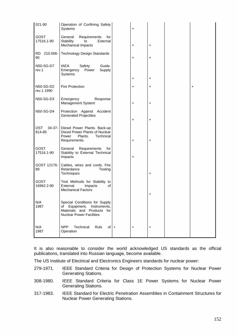
152
021-90 GOST 17516.1-90 RD 210.006-90 N50-SG-D7 rev.1 N50-SG-D2 rev.1 1990 N50-SG-D3 N50-SG-D4 OST 34-37-814-85 GOST 17516.1-90 GOST 12176-89 GOST 16962.2-90 N/A 1987 N/A 1987
Operation of Confining Safety Systems General Requirements for Stability to External Mechanical Impacts Technology Design Standards IAEA Safety Guide. Emergency Power Supply Systems Fire Protection Emergency Response Management System Protection Against Accident Generated Projectiles Diesel Power Plants. Back-up Diesel Power Plants of Nuclear Power Plants. Technical Requirements. General Requirements for Stability to External Technical Impacts Cables, wires and cords. Fire Retardance Testing Techniques Test Methods for Stability to External Impacts of Mechanical Factors Special Conditions for Supply of Equipment, Instruments, Materials and Products for Nuclear Power Facilities NPP Technical Ruls of Operation
+
+ + + + + + + + + +
+ + + + + + + + + +
+
It is also reasonable to consider the world acknowledged US standards as the official publications, translated into Russian language, become available.
The US Institute of Electrical and Electronics Engineers standards for nuclear power:
279-1971. IEEE Standard Criteria for Design of Protection Systems for Nuclear Power Generating Stations.
308-1980. IEEE Standard Criteria for Class 1E Power Systems for Nuclear Power Generating Stations.
317-1983. IEEE Standard for Electric Penetration Assemblies in Containment Structures for Nuclear Power Generating Stations.

153
323-1983. IEEE Standard for Qualifying Class 1E Equipment for Nuclear Power Generating Stations.
334-1974. IEEE Standard for Type Test of Class 1E Long-Run Electric Motors for Nuclear Power Generating Stations.
338-1977. IEEE Standard Criteria for Periodic Test of Power Systems and protection Systems for Nuclear Power Generating Stations.
379-1977. IEEE Standard Application of Single Failure Criteria for Class 1E Systems of Nuclear Power Generating Stations.
382-1980. IEEE Standard for Nomenclature of Safety Important Valve Drive Mechanisms.
383-1984. IEEE Standard for Type Test of Class 1E Electric Cables, Soldering and Connections for Nuclear Power Generating Stations.
384-1981. IEEE Standard Criteria for Class 1E Equipment and Trains Independence.
387-1983. IEEE Criteria for Diesel Generator Units As Back-Up Power Supply Sources of Nuclear Power Generating Stations.
450-1980. IEEE Recommended Practice for Design of Vented Lead-Acid Batteries for Stationary Applications.
484-1975. IEEE Recommended Practice for Installation Design and Implementation of Vented Lead-Acid Batteries for Stationary Applications.
603-1980. IEEE Standard Criteria for Safety Systems for Nuclear Power Generating Stations.
8.7. Marking The marking used in design shall be described.

154
CHAPTER 9. POWER UNIT AUXILIARY SYSTEMS
9.1. Nuclear fuel storage and handling systems
The introductory part of the subsection shall describe composition of the complex including the following systems:
1. Fresh (unirradiated) nuclear fuel storage and handling system.
2. The core refueling system.
3. INF handling system including:
• at-reactor INF storage system;
• arrangements for INF storage in the storage facility located outside the reactor hall in the specially built HP;
• shielded chamber (if available).
The nuclear fuel on-site transport arrangements shall be described starting from receipt of a fresh fuel vehicle to end with INF receipt (shipment), as well as on-site nuclear fuel shipments.
Describe the system for nuclear fuel accounting of existing at the NPP power unit.
9.1.1. Fresh (unirradiated) nuclear fuel storage and handling system
9.1.1.1. Purpose and categorization
The subsection shall contain information on the purpose of the system along with the functions it performs.
For the fresh nuclear fuel storage system and its elements it is required to indicate its class, category and group in terms of safety and seismic stability as per the categorization of applicable safety and seismic stability RDs.
There shall be a list of safety RDs, which requirements the system shall meet.
9.1.1.2. Design bases
The main principles and criteria laid in the system design shall be outlined.
The following shall be indicated for each storage facility:
• maximum design storage capacity; • storage standards; • characteristics of the fresh fuel intended for storage (enrichment, dimensions, activity, heat
release, etc.); • identification marking indicating enrichment of fuel in fuel assemblies and identification
means: visual and(or) by refueling devices; • identification marking for fuel assemblies, which contain burnable absorber, mixed fuel (if
available), means for their identification, etc.
Besides, there shall be a list of parameters, subsystems, system elements, which ensure safe functioning of the system as outlined in the design.
There shall be a list of design basis initiating events the system is designed to withstand. Present combinations of loads for the purpose of calculations.
List special requirements to the systems related to functioning of the main system.
Indicate main principles and criteria laid as the basis for the system configuration solutions.

155
9.1.1.3. Description of system
There shall be a description of design and (or) process flow diagram of the system as the whole, its subsystems, equipment, structures and elements should they perform independent functions.
Herein, provide for drawings, figures and diagrams to illustrate the design and operation of the system and its elements, its spatial arrangements and interfaces with other NPP power unit systems.
1. Description of system arrangement
Describe the inner layout of the storage facility; indicate a class of the storage facility and storage environs’ parameters (temperature, humidity, etc.), as well as the safety RD requirements. In particular, it shall be demonstrated that the layout of rooms and design solutions exclude a possibility for flooding and ingress of other moderating materials in the unirradiated fuel storage areas; that the provisions are in place for expedite evacuation of personnel from the rooms in case of an accident (type of an accident, evacuation routes, calculations of evacuation timeframe); there are no routes to other process premises running through the fuel storage areas (describe the access system and access control.) Describe the storage facility layout within the building and indicate how it is located with regard to other premises of the NPP power unit, NPP and adjacent systems.
The following shall be provided for (should such information be unavailable in Section 2):
• safety and seismic stability classification of the FFSF building and structures (if available); • ways and methods to provide for the prohibition of movement over the fuel in storage of
loads, which are not the parts of lifting and loading devices; in cases where loads are handled or placed above the storage facility covered by any structures, there shall be proofs that these structures withstand dynamic and static loads resulted from movement or placing of loads;
• information related to division of the FFSF buildings and premises into restricted access and free access areas;
• information on categories of the FFSF premises in terms of radiation and fire hazard and the information on the FFSF premises where radiation situation may rapidly change due to process operations;
• information stating that the principle of separation of ventilation of the restricted access area and ventilation of the free access area of FFSF is followed, and there are no common ventilation air ducts for the premises belonging with different service categories;
• information demonstrating that all fire (emergency) entrances to and exits from the restricted access areas are equipped with the leaktight doors;
• information confirming that the storage facility design is such that it allows, if necessary, for easy decontamination of surfaces, and the surfaces of the restricted access area are protected with materials having low RadS sorbent properties and are easily decontaminated.
If it is necessary to store fresh mixed uranium-plutonium fuel, proof of a possibility to store it in storage facilities designed to store fresh uranium fuel shall be provided for; or documents related to the design of modification for fresh fuel section and also possible modification of individual parts of transport corridors and individual elements of transportation and process equipment shall be submitted.
2. Description of fresh nuclear fuel storage system equipment
The fuel storage and handling equipment shall be indicated; its design shall be briefly described including the equipment used for transport and process and tilting operations, reactivation, inspection (incoming control) and repair of fuel assemblies (if available). Describe systems for handling of transportation packages should they be available in FFSF; in doing so, provide for the information regarding fulfillment of GSP requirements.
3. Information on any other equipment and materials stored in FFSF
The following shall be described:

156
• ways and methods to prohibit storage of flammable materials in FFSF, as well as the materials having other hazardous properties in case of fire and which are not parts of the packages:
• should FFSF store the core components other than nuclear fuel – provide for a list of such components and their locations as designed;
• ways and methods of how the storage of materials which are effective neutron moderators is prohibited between shrouds or inside shrouds, racks, groups of packages.
4. Provide for information about systems related to functioning of the fresh fuel storage and handling systems, as well as indicate the systems, subsystems, equipment, structures and elements performing independent functions: • information on location of each system, its constituting equipment, redundancy, designed
service life, working media, parameters, etc. The information shall contain parameters relevant to the system functioning. A parameter value shall be given along with its possible spread (allowance);
• localizing means designed to prevent or limit propagation of RadS and ionizing radiation resulted from accidents within the storage facility and into the environment;
• EAS for SCR initiation; • fire alarm; • regular and emergency lighting system; • CCTV (if available); • ventilation systems; • draining systems; • communications; • decontamination system; • storage facility district heating system.
Should the fresh mixed uranium-plutonium fuel be stored in the storage facilities designed for fresh uranium fuel, adequacy of systems related to the functioning of fresh fuel storage system shall be proved or design documents related to modernization of such systems shall be submitted.
9.1.1.4. Materials
The minimum scope of information regarding materials shall include:
1. Information on materials, including welding ones, intended for main system elements, along with their mechanical and process characteristics; there may be references given to the specifications, state standards, etc.; the information shall demonstrate that the procurement requirements for equipment, instrumentation and products intended for use at the nuclear power facilities are met; there shall be information confirming that these requirements are satisfied with regard to the FFSF transportation and handling equipment subject to the Rules for Layout and Safe Operation of Climbing Cranes (Chapter 4). 2. Information regarding permits to use the above materials including the permits to use non-metal materials (if available) should such permits be required by safety RDs (for example, as per the Special Procurement Conditions…); if such requirement is not imposed, the section shall contain the relevant entry. 3. Special information regarding resistance properties of materials, including absorbing admixtures to the FFSF structural materials (if any) to the conditions resulted from operations including decontamination, operational events, emergencies and accidents; this information shall demonstrate that the requirements of the Safety Rules for Storage and Transportation of Nuclear Fuel at Nuclear Power Facilities are met.
4. Special information which describes in particular:
• how the requirements related to incombustibility or low combustibility of lining, finishing, soundproof, and thermal insulation materials used for the FFSF inner finishing are met;
• that the fencing structures of FFSF are made of incombustible materials and have a fire-resistance rating as required;

157
• that the surfaces of the FFSF premises and FFSF equipment are protected by the materials with low RadS absorbing properties, are waterproof and easy to decontaminate;
• information on hazardous properties of the structural materials in use including those stored in FFSF (if any) in case such properties may manifest themselves during normal operation, operational events, emergencies and accidents.
9.1.1.5. System performance monitoring and control There shall be a list and justification of permitted values of monitored parameters of the system in all operational modes and when the system is under repair; locations of monitoring points; description of monitoring methodology; information on metrological qualification of the methodologies in use; requirements to instrumentation and controls. The interconnections of the system with the power unit control systems shall be described along with the redundancy arrangements of the sensors and communication trains (while writing the subsection it is permitted to refer to the information in Chapters 7 and 8).
The monitoring systems shall be described along with indication of the measuring schemes, points and techniques, monitored parameters, protective features actuation settings, accuracy and frequency of measurements, assessment criteria and methodology.
There shall be information on availability of the monitoring and alarm devices and systems in FFSF.
The information about all types of monitoring and alarms shall be presented.
9.1.1.6. Quality assurance
There shall be information on the quality assurance program, which corresponds with the requirements of GSP and the Requirements for Quality Assurance Program of Nuclear Power Plant.
9.1.1.7. Commissioning
Herein, present information consistent with the requirements of Chapter 13.
9.1.1.8. Tests and inspections
Herein, present information on regulations and procedures of the periodic check of FFSF equipment and systems during operation.
There shall be information on techniques, scope and timeframes of in-service inspections of NPP systems conditions and their tests; describe the measures provided for these purposes in design; and demonstrate that they meet the safety RD requirements.
9.1.1.9. Normal functioning of system
There shall be a description of how the system functions in normal operation conditions and interacts with other systems.
Herein, present information on operating procedures relevant to the fresh fuel storage and handling system in the scope corresponding to the requirements of Chapter 14.
9.1.1.10. System performance under failures
There shall be an analysis of the system element failures including personnel errors, and an assessment of the failure consequences, including that resulted from common cause failures, to the system operability and NPP power unit safety as the whole.
9.1.1.11. System reliability analysis
1. Herein, describe computer codes used to analyze the system reliability, input data for calculations, assumptions and constraints used in the algorithms and calculation schemes,
158
calculation results and conclusions. Present information on verification and certification of the computer codes.
The scope of information shall be sufficient to carry out independent calculations. Should experiments have been performed to justify the design reliability, the experimental facility and experiment conditions shall be described; an analysis of their correspondence with the design conditions, metrological support of the experiments, and interpretation of the results with regard to the design conditions shall be presented.
There shall be a list of initiating events, failures, external impacts, operator’s errors and their combinations, which shall be considered in the course of analysis of accidents in the system and NPP reliability analysis as per Chapter 15.
2. There shall be quantitative reliability indicators of the FFSF equipment in accordance with the manufacturing specifications.
Herein, provide for a qualitative analysis of the system reliability and determine quantitative values of the system reliability indicator (transportation and process flow diagram of receipt and feeding of fresh fuel).
The calculation of quantitative indicators of the system reliability shall be preceded by a brief description of the computer code including assumptions, constraints and verification information.
There shall be results of calculations done to determine quantitative reliability indicators, analysis of the results obtained, and conclusions regarding their acceptability or unacceptability.
The scope of information shall be sufficient to carry out independent alternative calculations, if necessary.
9.1.1.12. Evaluation of fresh nuclear fuel storage design
The subsection shall be concluded with an analysis of compliance with the safety RD requirements.
The conclusions shall be formulated taking account of how the criterion of satisfactory compliance of the fresh fuel storage and handling systems with safety requirements and GSP requirements is formulated in the design.
There shall be an assessment of how the RS principles outlined in the RSS and Radiation Safety Rules for Nuclear Power Plants are fulfilled.
Describe ways and methods applied to determine a permissible number of packages or shrouds in the group of pier.
9.1.2. Core refueling system
There shall be requirements set forth for the core refueling system.
9.1.2.1. Purpose and classification
There shall be information on the purpose and classification of the core refueling system elements.
9.1.2.2. Design bases
The information given in para. 9.1.1.2 shall be used.
9.1.2.3. Description of refueling system
1. Description of process flow diagram.

159
There shall be a description of the process flow diagram related to refueling operations along with indication of equipment, devices and elements performing independent functions. Indicate the specific equipment constituting the system.
Describe the design process flow diagram for refueling operations regarding unloading of the core and its components, indicate its difference from the refueling operations along with the special equipment to be used.
In particular, the following shall be described (indicated):
• ways and methods of identifying the fuel assemblies and (or) elements of the core being unloaded for their compliance with the refueling plan;
• the chosen refueling technique and its justification; • state of the refueling compartment during refueling; • system and design of the charging unit for placing elements of the core into the reactor; • refueling frequency, scope and procedure and their justification; • design engineered means to prevent accidental alien objects in reactor during refueling and
repair; • describe the composition of the refueling system along with justification of sufficiency of
constituents available; outline the requirements set forth for the system, which ensure safety at fuel assemblies’ handling including that in case of failures and damage;
• engineered means to remove heat from fuel assemblies being reloaded.
In addition, the following shall be described:
• measures to prevent damage, deformation, destruction or drop of fuel assemblies; • measures to prevent impermissible forces on fuel assemblies in the course of fuel
assemblies’ withdrawal or insertion; • technical means to prevent fuel assemblies’ drop should power supply be lost; • design protective features that provide for refueling mechanism movements within
permissible limits; • design equipment provided for reliable transport of the fuel to safe locations in case of a
failure or operational event of the refueling devices; • process engineered means, which prevent withdrawal of fuel assemblies with high residual
heat; • boards (panels) arranged for at the refueling devices to display information on positioning
(state) and orientation of fuel assemblies and grips.
2. It shall be demonstrated that all loads arising from normal operation including asymmetric loads and acceleration loads were considered during design process related to refueling equipment; in doing so, it shall be demonstrated that stresses resulted from loads do not exceed permissible limits set forth for various equipment elements.
3. A justification of the refueling system operability shall be presented.
4. There shall be information on the systems related to functioning of the core refueling systems. There shall be brief information on location of each such system, its constituents, redundancy, intended service life, working media, parameters, etc.
The information about following systems shall be given:
• CCTV for monitoring of the refueling process along with the list of refueling operations to be monitored by CCTV;
• cladding integrity inspection; • regular and emergency lighting; • fire extinguishing; • ventilation and air clean-up; • communications and warning;

160
• emergency alarms.
9.1.2.4. Materials
The information on materials in use shall be given. The description shall be in the scope as per para. 9.1.1.4.
9.1.2.5. System performance monitoring and control
There shall be a list of the system parameters monitored during operation and repair along with a justification of the permissible values; indicate the locations of monitoring points, describe monitoring methodologies, provide for information regarding metrological qualification of the methodologies in use, and requirements to instrumentation and controls.
The interfaces of the system with the controlling systems, redundancy of sensors and communication trains shall be described
The protective features and interlocks shall be described.
Operability of all refueling control and monitoring systems shall be justified along with description of their functions. While compiling the section, it is permitted to refer to Chapters 7 and 8.
9.1.2.6. Quality assurance The quality assurance information regarding the nuclear fuel refueling system shall correspond to the requirements of Chapter 17.
9.1.2.7. Commissioning
The commissioning information regarding the nuclear fuel refueling system shall correspond to the requirements of Chapter 13.
9.1.2.8. Tests and inspections
Herein, present information on regulations and procedures for periodic inspections of nuclear fuel refueling equipment and systems during operation; on techniques, scope and timeframes of in-service inspections of systems’ conditions and their testing; describe the measures provided for these purposes in design; and demonstrate that they meet the safety RD requirements.
9.1.2.9. Safe operation conditions
Herein, describe the safe operation conditions of the reactor during refueling operations.
9.1.2.10. System reliability analysis
Herein, present the information in accordance with requirements outlined in para 9.1.1.11, as regards the nuclear fuel refueling system.
9.1.3. Spent (irradiated) fuel handling systems
9.1.3.1. At-reactor SNF storage system
1. Purpose and classification
2. Design bases
Herein, present the information in accordance with requirements outlined in para. 9.1.1.2, as regards the at-reactor SNF storage system.
3. Description of system
161
There shall be a description of design and (or) process flow diagram of the system as the whole and its subsystems, equipment, structures and elements should they perform independent functions.
Herein, present detailed drawings, figures, schematic views illustrating the design and functioning of the system and its elements, it spatial arrangement and interfaces with other NPP unit systems.
The descriptions shall be supplemented with the parameters corresponding to the functions they perform.
4. Description of process flow diagram
The maximum design heat removal capacity in the spent fuel drum, storage environs’ parameters (temperature, pressure, etc.) and SNF storage guidelines shall be indicated for the off-reactor SNF storage system. It shall be demonstrated that the HP capacity is capable of holding nuclear fuel to reduce radioactivity and heat release, as well as that the arrangements are in place to ensure unloading of the full core at any moment of operation.
Herein, describe the characteristics of the fuel intended for storage (burnup, activity, heat release, etc.).
Present information on any other elements, especially fresh fuel, which temporarily or long-term stored in the at-reactor SNF storage facilities, along with causes for storing them, storage periods of time and guidelines, as well as properties of these elements.
Describe HP and transportation and process equipment layout in the NPP unit building, and their locations with regard to other adjacent NPP unit premises and systems.
Describe HP design, process flow diagram of SNF storage and indicate subsystems, equipment and elements performing individual functions.
Should the spent mixed uranium-plutonium fuel be stored in the off-reactor storage facilities designed for spent uranium fuel, organizational and technical measures to provide for storage of damaged or leaking spent mixed uranium-plutonium fuel assemblies shall be presented.
Describe support and building structures of the spent fuel drum as regards their effects to safety.
It shall be demonstrated that:
• the HP design provides for detection of leaks; • there are arrangements to cool irradiated nuclear fuel in case of design and beyond design
basis accidents.
Herein, describe designs of the equipment used for placing and storage of SNF including the leaking FAs, as well as the equipment for storage of other elements of the core (if available).
Provide for constituents of specific equipment pieces of the SNF storage system and indicate whether this equipment meets the safety RD requirements.
5. Information on the systems related to functioning of SNF storage and handling system
There shall be information on location of each system, its equipment, redundancy, intended service life, working media, parameters, etc.
The parameters corresponding to the functions of the system being described shall be indicated. The parameter value shall be given taking account of its possible spread (allowance).
The information of the following systems shall be presented:
• CfSS designed to prevent or limit proliferation of RadS and ionizing radiation resulted from accidents within the storage facility and into the environment;
• coolant; • HP filling and draining; • make-up;

162
• cooling service loop; • ventilation and air clean-up; • process control; • fire extinguishing; • communication and warning; • emergency alarms.
Functions of the above systems shall be described and their operability shall be proven (references to other sections containing such proofs are permitted).
As regards storage of the spent mixed uranium-plutonium fuel, a proof of the possibility to use the at-reactor storage facilities designed for spent uranium fuel including systems related to the functioning of the NF storage system shall be presented, or design documents related to modernization of such systems shall be provided.
6. Materials
The requirements to structural material shall be described in the scope as per para. 9.1.1.4.
7. System performance control and monitoring
The requirements to the system control and monitoring shall be described in the scope as per para. 9.1.2.5.
8. Tests and inspections
The scope and methodologies of the incoming control, interagency, pre-start-up alignment tests, and their metrological support shall be justified; a list and permissible values of the parameters monitored in the course of above activities shall be presented and justified as well as the requirements to I&C used during the tests.
9. Quality assurance Systems, equipment and processes of the storage facility, as well as the system building structures, subject to NPP QAP shall be indicated.
The SAR shall demonstrate that the structural materials, manufacturing techniques, procurement and storage conditions, etc. complied with the design documentation requirements and RDs; also the actual changes and deviations (if any), including deviations from specific design and RD requirements shall be justified with references to the documents where such deviations are recorded.
Herein, provide for the information on NPP QAP as a whole.
10. Commissioning
The information on commissioning of the off-reactor nuclear fuel storage system in general shall correspond to the requirements outlined in Chapter 13. The HP test results shall confirm that the HP lining ensures the required integrity level and withstands design impacts, etc.
11. Operation
There shall be information regarding operations regulations and procedures for periodic in-service inspection of the off-reactor nuclear fuel storage system’s equipment.
Herein, present information on techniques, scope and timeframes of in-service inspections of systems’ conditions and their testing; describe the measures provided for these purposes in design; and demonstrate that they meet the safety RD requirements.
Present the information on operating procedures of the at-reactor nuclear fuel storage system in the scope that corresponds with the requirements of Chapter 14.
12. System reliability analysis
This paragraph shall be in the scope as per para. 9.1.1.11.
13. Evaluation of design
163
Herein, present an analysis of how the requirements, principles and criteria established by the relevant safety RDs are met.
The conclusions shall be formulated taking account of how the criterion of satisfactory compliance of the fresh fuel storage and handling systems – NPP with safety requirements and GSP requirements is formulated in the design.
9.1.3.2. System for SNF storage under water or other coolant in a storage facility located outside the reactor hall in an especially built hold-up pond
1. Purpose and classification
2. Design bases
The scope of this paragraph shall be in accordance with that of para. 9.1.1.2, as regards the SNFSF.
3. Description of system
There shall be a description of design and (or) process flow diagram of the system as the whole and its subsystems, equipment, structures and elements should they perform independent functions.
Herein, present detailed drawings, figures, schematic views illustrating the design and functioning of the system and its elements, it spatial arrangement and interfaces with other NPP unit systems.
The parameters corresponding to the functions of the system being described shall be indicated. The parameter value shall be given taking account of its possible spread (allowance).
4. Description of process flow diagram
There shall be a description of the process flow diagram.
5. Information on the systems related to functioning of SNFSF
There shall be information on location of each system, its equipment, redundancy, intended service life, working media, parameters, etc.
The parameters corresponding to the functions of the system being described shall be indicated.
The information of the following systems shall be presented:
• CfSS designed to prevent or limit propagation of RadS and ionizing radiation resulted from accidents within the storage facility and into the environment;
• water cooling (except for the cases where it has been proven that the design temperature values of storage facility water will not be exceeded without special cooling);
• water treatment; • HP filling and draining (drain system); • make-up; • water supply; • collection of radioactive water drains into controlled collectors (collection and return of
drains); • emergency make-up; • ventilation and air clean-up; • underwater lighting; • fire extinguishing; • communications and warning; • emergency alarms; • electric power supply.
As regards storage of the spent mixed uranium-plutonium fuel, proof of a possibility to use the off-reactor storage facilities designed for spent uranium fuel including systems related to the

164
functioning of the NF storage system shall be presented, or design documents related to modernization of such systems shall be provided.
6. Materials
This paragraph shall be in the scope as per para. 9.1.1.4.
7. Control and monitoring
This paragraph shall be in the scope as per para. 9.1.1.5.
8. Quality assurance
Systems, equipment (elements) and processes of the storage facility, as well as the system building structures, subject to NPP QAP shall be indicated along with the corresponding monitoring and verification techniques and methods.
Herein, provide for the information on NPP QAP corresponding to the requirements of GSP and the Requirements to Quality Assurance Programs of Nuclear Power Plants.
9. Tests and inspections
The scope and methodologies of the incoming control, interagency, pre-start-up alignment tests, and their metrological support shall be justified; a list and permissible values of the parameters monitored in the course of above activities shall be presented and justified as well as the requirements to instrumentation and controls used during the tests.
10. Commissioning
The information on commissioning of the SNFSF in general shall correspond to the requirements outlined in Chapter 13.
11. Operation
This paragraph shall be in the scope as per paras. 9.1.1.9 and 9.1.1.10.
12. Analysis of system reliability
There shall be information as per the requirements of para. 9.1.1.11.
9.1.3.3. System for “dry” SNF storage in a storage facility located outside the reactor hall in an especially built building (SNFSF) – “dry storage” (if available).
1. Purpose and classification
2. Design bases
The scope of this paragraph shall be in accordance with that of para. 9.1.1.2, as regards the “dry” storage.
3. Description of system
There shall be a description of design and (or) process flow diagram of the system as the whole and its subsystems, equipment, structures and elements should they perform independent functions.
Herein, present detailed drawings, figures, schematic views illustrating the design and functioning of the system and its elements, it spatial arrangement and interfaces with other NPP unit systems.
The parameters corresponding to the functions of the system being described shall be indicated. The parameter value shall be given taking account of its possible spread (allowance).
4. Description of process flow diagram
There shall be a description of the process flow diagram.
5. Information on the systems related to functioning of the system for “dry” SNF storage
There shall be information on location of each system, its equipment, redundancy, intended service life, working media, parameters, etc.

165
The parameters corresponding to the functions of the system being described shall be indicated.
The information of the following systems shall be presented:
• CfSS designed to monitor and limit accumulation of RadS within the storage facility and propagation of RadS and ionizing radiation resulted from accidents into the environment;
• systems providing for heat removal from OSTP (on-site transportation packages) taking into account that design temperature values for the OSTP outside surface are not exceeded;
• temperature monitoring; • monitoring of water ingress into the OSTP; • ventilation; • radiation monitoring; • fire extinguishing; • communications and warning; • emergency alarms; • power supply of systems and supporting devices.
6. Materials
This paragraph shall be in the scope as per para. 9.1.1.4.
7. Control and monitoring
This paragraph shall be in the scope as per para. 9.1.1.5.
8. Quality assurance
Systems, equipment (elements) and processes of the “dry” storage facility, as well as the system building structures, subject to NPP QAP shall be indicated along with the corresponding monitoring and verification techniques and methods.
Herein, provide for the information on NPP QAP corresponding to the requirements of GSP and the Requirements to Quality Assurance Programs of Nuclear Power Plants.
9. Tests and inspections
The scope and methodologies of the incoming control, interagency, pre-start-up alignment tests, and their metrological support shall be justified; a list and permissible values of the parameters monitored in the course of above activities shall be presented and justified as well as the requirements to instrumentation and controls used during the tests.
10. Commissioning
The information on commissioning of the system for “dry” SNF storage in general shall correspond to the requirements outlined in Section 13.
11. Operation
This paragraph shall be in the scope as per para. 9.1.1.9 and 9.1.1.10.
12. Analysis of system reliability
There shall be information as per the requirements of para. 9.1.1.11.
9.1.3.4. Shielded chamber system
1. Design bases
The information shall be presented in accordance with the requirements of para. 9.1.1.2 as regards the shielded chamber system.
2. Description of system
There shall be a description of design and (or) process flow diagram of the system as the whole and its subsystems, equipment, structures and elements should they perform independent functions.

166
Herein, present detailed drawings, figures, schematic views illustrating the design and functioning of the system and its elements, its spatial arrangement and interfaces with other NPP unit systems.
The parameters corresponding to the functions of the system being described shall be indicated.
3. Description of process flow diagram
There shall be a description of the process flow diagram.
In addition, the following shall be presented:
• information on how the access to the shielded chamber premises is arranged; • evidence of that the requirements of sanitary rules are met; • information on the SNF handling bays within the shielded chamber system where the
radiation situation may instantly change in the course of the process operations.
4. Information on the systems related to functioning of the shielded chamber
There shall be brief information on location of each system, its equipment, redundancy, intended service life, working media, parameters, etc.
The parameters corresponding to the functions of the system being described shall be indicated.
The information of the following systems shall be presented: • CfSS designed to prevent or limit propagation of RadS and ionizing radiation resulted from
process operations and (or) accidents within the storage facility and into the environment; • ventilation and air clean-up; • lighting (regular and emergency); • independent service water supply system; • decontamination; • gas supply; • depressurizing; • power supply of systems and supporting devices; • fire extinguishing; • communications and warning; • emergency alarm.
It shall be demonstrated that all above systems meet the safety RD requirements.
5. Materials
This paragraph shall be in the scope as per para. 9.1.1.4.
6. Control and monitoring
There shall be a list of system parameters monitored during operation and repair along with justification of the permissible values; indicate the locations of monitoring points, describe monitoring methodologies, provide for information regarding metrological qualification of the methodologies in use, and requirements to instrumentation and controls. Describe the system’s interfaces with the power unit controlling systems, redundancy of sensors, communications trains.
The monitoring systems shall be described along with the diagrams, points and techniques of measurement taking, monitored parameters, protective features actuation settings (for example, for fire protection), accuracy and frequency of measurements, assessment criteria, and assessment methodologies.
It shall be proven that the system control and monitoring ensure compliance with the GSP requirements as regards timely identifying of defects and revealing violations in operation to take measures to eliminate them.

167
For the shielded chamber all control devices and systems shall be indicated.
7. Quality assurance
Herein, provide for the information on NPP QAP corresponding to the requirements of GSP and the Requirements to Quality Assurance Programs of Nuclear Power Plants.
8. Tests and inspections
There shall be a list of periodic in-service inspections and tests.
9. Commissioning
The information on shielded chamber commissioning shall correspond to the requirements of Chapter 13. It shall be demonstrated that the requirements of GSP are met.
10. Operation
This paragraph shall be written similarly to paras. 9.1.1.9 and 9.1.1.10 with regard to the shielded chamber system.
11. Evaluation of design
There shall be information on whether the system complies with the safety RD requirements.
9.1.4. On-site nuclear fuel transportation system
9.1.4.1. Purpose and classification
9.1.4.2. Design bases
This paragraph shall be presented in the scope of para. 9.1.1.2 as regards the on-site nuclear fuel transportation system.
9.1.4.3. Description of system
There shall be information on the vehicle parking lot location and location of the on-site railways for nuclear fuel transportation; techniques and scope of incoming inspection of the nuclear fuel containers; techniques for moving of nuclear fuel from railcars to the storage facility; on-site nuclear fuel transportation routes; techniques to move nuclear fuel to the NPP units in on-site transport containers by specialized vehicles.
The systems related to functioning of the on-site nuclear fuel transportation system shall be described in this subsection to maintain the information integrity and to the extend where they may be considered as parts of the given system.
Should the necessary information be presented in other section or subsection, this section shall refer to it.
There shall be brief information on location of each system, its equipment, redundancy, intended service life, working media, parameters, etc.
9.1.4.4. Control and monitoring
There shall be a description of control and monitoring procedures for transportation of nuclear fuel.
9.1.4.5. Test and inspections There shall be information on in-service inspections, checks and tests. 9.1.4.6. Operation There shall be a brief description of main operating procedures. 9.1.4.7. Evaluation of design Herein, provide for the information on the system compliance with the safety RD requirements.

168
CHAPTER 10. RADIOACTIVE WASTE MANAGEMENT
The Chapter shall include the information related to the gaseous, liquid and solid NPP RW management, present possible paths of the RW ingress into the environment and describe RW management methods.
It shall be demonstrated how the RW management principles applied to the design comply with the ALARA principle.
10.1. RW generating sources The Section shall address RW generating sources, which specific parameters serve as the basic input data for developing management systems for all RW types generated in case of both normal NPP operation and accidents.
Parameters used in defining the activity of each of the radionuclides in the primary and secondary coolant shall be presented; and available assumptions shall be justified.
Quantitative characteristics of RadS (radionuclides) ingressing into the coolant as a result of the loss of fuel element cladding integrity shall be justified by the calculated values that take into account heat load on the fuel elements and other needed parameters; and also by the available operational experience with regard to the similar fuel assemblies including accident-related experience, temperature modes and the fuel burn-up level.
The data related to the concentrations (activity) of the radionuclides of the fission and corrosion products and used in calculating the equipment and waste energy radiation spectrum shall be presented. In that, it should be demonstrated how the water activation and activation of impurities contained in the water are taken into account. Radionuclide composition of the waste, the mechanism of its generation and data related to the radionuclide concentration in the waste shall be presented. In that, the use of the known operating experience shall be included.
Simulators (mathematical models) used to calculate the input data (flow rate, concentration, energy spectrums and so on) that is taken into account in the development of the RW management system design taking into consideration parameters of the normal operation and transients shall be described.
The design values of the controlled and uncontrolled leaks of the primary and secondary coolant, coolant of the auxiliary equipment circuit, the equipment decontamination water, etc. that represent sources of the possible RadS ingress into the environment should be systematized.
Data on the sources of the leaks and fluxes, their values and also their estimated contribution values to the general radioactivity level shall be presented in a form of a table including comparison of the above mentioned values with the data for the operation of the similar operating units.
The assessment of the RadS ingress into the premises in the form of the liquids, gases and aerosols in terms for the each radionuclide shall be presented indicating the paths for their consequent transport, discharge and release into the environment. The methods to measure leaks and special design means to reduce leak values shall be described. A reference to the relevant operational experience related to the existing NPPs shall be made.
The systems that may be sources of the possible RadS releases (discharges) during their operation or maintenance, but, however, are not attributed to the RW management systems (for example, blow-off system for the steam-generator, air cleaning system of the containment and so on) shall be specified. RadS (radionuclide) release assessments shall be presented including description of the mechanism for their possible transfer, transport and ingress into the environment for each of the mentioned sources in case of the normal operation and also possible failures. The data on the leak flows, radionuclide concentrations and other parameters that are sufficient for making estimated assessments shall be included. The design solutions related to confining of these sources shall be described, it shall be demonstrated how the

169
experience of the preceding designs and well-known design solutions has been taken into account, shall be demonstrated.
Analysis of the principal design solutions related to reduction of RadS (radionuclide) content in the primary coolant in comparison with the NPP design of the preceding generations shall be included. Comparison of the design data and operational data for the similar operating units shall be presented.
10.2. Gaseous RW management systems The Section shall describe all NPP systems that are potential sources of the RadS release into the environment in the form of gases or aerosols including the ventilation systems of the restricted access area of the buildings, process blow-off systems, turbine ejectors, ventilation of the turbine hall and so on. The SAR NPP shall contain description of the NPP design capabilities related to gaseous waste management under all the operational modes including emergency situations in the considered systems and design basis accidents at the NPP.
10.2.1. Design bases
The Subsection shall specify the basic safety principles and criteria that are implemented in the design and/or process diagrams of the systems and specific paragraphs of the existing safety RD.
As regards the main system components, the class, category and group shall be indicated in accordance with the classification presented in the existing RD related to safety and seismic resistance. Data on classification of the system and its components is included into this Section in order to ensure integrity of the information about the system. A reference to the other sections of the Report can be made, should these sections contain the necessary information. It is desirable to present the information in the form of the tables. Calculation objectives and criteria for the systems shall be presented including anticipated annual RadS releases and anticipated exposure doses for the personnel and population caused by the impact of these RadS releases.
This description shall include an assessment, which demonstrates that the implemented principles and the relevant technologies enhance efficiency (including cost-related efficiency) of the waste reprocessing. The assessment shall demonstrate that the accepted systems incorporate all state-of-the-art technological achievements targeted to reduce the personnel and population exposure.
All used computation methods and assumptions shall be presented. It shall be demonstrated how the site features addressed by Chapter 2 were taken into account with regard to meteorological and hydrological conditions.
The assessment, which demonstrates that the systems have sufficient capacity and needed redundancy in order to provide for cleanup from RadS under all the operational modes in case of loss of the fuel element integrity that corresponds to the safe operation limit depending on the RI type, shall be included. It is necessary to demonstrate (basing on the conducted evaluations of the system capacity) that the system provides for non-exceeding the permissible standards for the releases under all design modes: during the normal operation, in case of the operational event and accidents. Features of the design that include means to reduce the scope of maintenance, equipment idling, possibility of the RadS ingress into the premises, means to enhance efficiency of the medium cleanup methods shall be described. The accepted calculated values of the radionuclide activity in all system components are required to be presented including the input data needed to identify these values. Layout and geometry of the systems’ equipment shall be presented for calculations of the biological shielding in accordance with the Section 11.3.
The design measures targeted to monitor the RadS (radionuclide) ingress beyond the gaseous RW management systems shall be described. Possible errors of an operator and single failures
170
that can result in uncontrolled releases into the environment shall be demonstrated. The design means to monitor releases caused by the possible equipment failures or operator’s error shall be described. Efficiency of the preventive measures of the exposure dose monitoring and system control, automatic limitation of the release value, should this value exceed the established limits, shall be justified.
It is necessary to list all equipment of the systems where explosive concentrations of gases may be generated, and also to specify design pressure and to present justification of the equipment accepted in the design. Process I&C (including gas analyzer), design measures targeted to prevent explosions and full loss of the integrity caused by the explosion shall be described.
Section 10.5 shall describe the radiation monitoring systems for the processes and releases.
10.2.2. Description of the systems The systems shall be described in accordance with the structure presented in the Appendix to the Section “General Requirements”. In that, the Section shall describe each gaseous RW management system and gas flow diagrams that show process equipment, gas routes in the system, capacity of the system and appropriate equipment, back-up equipment. As regards complicated multifunctional systems, those subsystems shall be specified including the equipment description that can be divided into independent parts. For the each system, maximum and regular input data for the gas flow rate and RadS (radionuclide) concentration for the all operational modes shall be presented in the form of the table or indicated on the diagrams. Input data used to identify the mentioned values shall be indicated. The content of the gas flow shall be included and the technology to manage the hydrogenous flows shall be specified.
Interlinks of the systems and system boundaries regarding the equipment of different classification groups shall be indicated on the process flow diagrams.
System instrumentation and controls shall be specified.
By-pass lines available shall be demonstrated as well as conditions that affect their use, and also anticipated frequency of the use of the by-pass lines in connection with the equipment idling. Location of the tanks-hydroseals (pressure locks) shall be presented; and measures targeted to prevent loss of their operability shall be described. Location of the ventilation holes and secondary circulation paths for the each system shall be indicated. Both the normal operational mode and all operational modes including gas clean-up under the containment shall be described. Ventilation systems of the each of the buildings, where RadS may occur, shall be described. The description shall include volumes of the buildings, anticipated flow rates in the ventilation system of the buildings and their premises, characteristics of the filters and those calculation criteria that found a basis for identifying these values. Description of both the normal operational mode of the each ventilation system and the operational features for the different NPP operational modes including the design basis accidents shall be presented. The table addressing the design concentrations of dispersed RadS (radionuclides) suspended in the air of the building premises and corridors shall be presented for all operational modes including the design basis accidents.
The other NPP systems that are potential sources of the gaseous RW, such as the turbine ejectors and so on, shall be described. The RadS concentrations for all operational modes including the design basis accidents shall be specified. It is required to indicate the input data for identifying these concentrations.
Data on the anticipated frequency and volume of the released steam during its discharge into the atmosphere in case of the possible actuation of the primary and secondary safety equipment shall be tabulated including the input data for these characteristics. If necessary, a reference to the other SAR NPP chapters shall be made.

171
10.2.3. RadS releases The Section shall address criteria to be applied in case of the gaseous RW release; and the accepted release standards. The parameters and assumptions used in calculating the RadS (radionuclides) in the gaseous waste and reasons for their selection shall be presented. The anticipated volumes of the gaseous waste under all operational modes including the emergency situations shall be specified. Magnitudes of the gaseous releases for the each sub-system and the system, in whole, shall be tabulated.
The anticipated radionuclide concentrations in the gaseous waste under all operational modes including the design basis accidents (in Ci/year per reactor) shall be presented. The table shall include the radionuclide concentrations for the each sub-system and the system, in whole.
The design data shall be presented for the operational limit of fuel element damage in accordance with the ToR for the NPP taking into account the possible additional fission products’ release from the fuel into the coolant during the transients and the unit shutdown.
It is necessary to forecast a possible short-term RadS content increase in the gaseous RW when the safe operation limit in terms of the loss of the fuel element integrity according to the RD is achieved.
The following shall be specified: assumptions used in that, including dilution coefficients; all points of the gaseous RW release into the environment - on the process diagrams for the gas flows and the general NPP layout drawings. It is desirable to present the information in the form of tables and diagrams. The operational data related to the annual RadS releases into the environment from the nuclear power units, which are the prototypes to NPP under design shall be presented. The comparative analysis of the presented information shall be conducted.
As regards the ventilation exhaust ducts, the height of the foundation, the outlet height, inner diameters, the discharged gas flow rates, gas temperature shall be presented.
As regards the ventilation outlets of the buildings and other discharge devices, the general description of the outlets, their configuration, flow rate, gas temperature shall be presented.
10.3. Liquid RW management systems The Section shall describe all NPP systems for the liquid RW management, the basic characteristics of the liquid RW management systems for the all operational modes including design basis accidents.
10.3.1. Design bases The Subsection shall specify the basic safety principles and criteria that are implemented in the design and/or process diagrams of the systems and concrete paragraphs of the existing safety RD. As regards the systems and, if necessary, their main components, the class, category, group, type, etc. shall be indicated in accordance with the classification presented in the applied RDs for safety, seismic resistance, radiation hazard level and the like. The classification-related data of the system and its components is included into this Section in order to ensure integrity of the information about the system. A reference to the other sections of the Report can be made under the condition that these sections contain the necessary information. It is desirable to present the information in the form of the tables.
Calculation objectives and criteria for the systems shall be presented including average anticipated amount of the liquid RW (radionuclides) generated annually and during the whole NPP operating period, anticipated exposure doses for the personnel and population caused by the impact of this RW.
This description shall include the assessment, which demonstrates that the implemented principles and the relevant technologies enhance efficiency (including cost-related efficiency) of
172
the reprocessing of the abovementioned RW amount. The solidification technologies for the liquid RW shall be described; and it is required to demonstrate that the accepted systems incorporate all state-of-the-art achievements of the technology targeted to reduce the personnel and population exposure. All used computation methods and assumptions shall be presented. It shall be demonstrated how the site features addressed by Chapter 2 were taken into account with regard to meteorological and hydrological conditions. The assessment, which demonstrates that the systems have sufficient capacity and needed redundancy in order to provide for cleanup from RadS under all the operational modes in case of loss of the fuel element integrity that corresponds to the safe operation limit depending on the RI type, shall be included. It is necessary to demonstrate (basing on the conducted evaluations of the system capacity) that the system provides for the cleaning from the RadS during all operational modes, in case of the operational events and accidents. Features of the design that include means to reduce the scope of maintenance, equipment idling, the RadS ingress into the premises, means to enhance efficiency of waste reprocessing methods. The accepted calculated values of the radionuclide activity in all system components are required to be presented including the input data needed to identify these values. Layout and geometry of the systems’ equipment for calculations of the biological shielding in accordance with Section 11.3 shall be presented. Possible operator’s errors and single failures that can result in uncontrolled RadS discharges into the environment shall be demonstrated. Efficiency of the preventive measures including both the process measures and measures using protection, interlocks, I&C systems shall be demonstrated. The design measures and control means for preventing unpremeditated and uncontrolled RadS discharges into the environment shall be described. Section 10.5 shall describe the health physics and radiation monitoring systems for the processes and discharges.
10.3.2. Description of the systems The systems shall be described in accordance with the structure presented in the Appendix to the Section “General Requirements”. The description of each system shall include the process diagrams that outline the equipment, normal direction of the liquid flows, capacity of the system and appropriate equipment, back-up equipment. As regards complicated multifunctional systems, those subsystems that can be divided into independent parts shall be indicated including the appropriate equipment description. Management technology for all possible liquid RW shall be described.
For the each system, maximum and normal input data for the liquid flow rate (in m3/day per a reactor) and radioactivity value (expressed in the primary coolant activity fractions) for the all operational modes including the design basis accidents shall be presented in the form of a table or indicated on the diagrams. Input data used to identify the mentioned values shall be indicated.
Liquid RW flow separation, principles for the RW liquid flow separation in terms of the physical and chemical RW properties, the radioactivity value, etc. shall be described. All possible by-pass lines shall be demonstrated as well as conditions that affect their use, and also forecasted frequency of the use of the by-pass lines in connection with the equipment idling.
Interaction of the systems and system boundaries regarding the equipment of different classification groups shall be indicated on the process diagrams. Those equipment components and units, and pipelines that contain the increased radionuclide concentration should be indicated on the diagrams with a purpose of providing information needed for assessments addressed in Chapter 11.
All normal operation modes of the each system and distinctions during the periods of different NPP operational modes including the design basis accidents shall be described.

173
10.3.3. RadS discharges The parameters and assumptions used in calculating the radioactivity (radionuclide) discharge and the input data used for that shall be presented taking into account the part of the liquid waste that have been already treated and can be included into the closed cycle to be reused. The anticipated magnitude of the RadS (radionuclide) discharge during all operational modes including the emergency situations and the design basis accidents (in Ci/year per a reactor) shall be presented. The table shall be presented including the radionuclide discharge magnitudes for the each sub-system and also the discharge concentrations. All the points of the liquid RadS discharges and dilution coefficients that are taken into account in evaluating the specific volume activities shall be specified. It is desirable to present the information in the form of tables and diagrams. The operational data related to the annual RadS releases into the environment from the Units being the prototype of the designed NPP shall be presented. The comparative analysis of the presented information shall be conducted. The forecast of the short-term maximum possible daily RadS discharge into the environment from the NPP shall be presented for the case where the safe operation limit for fuel element in terms of the loss of its integrity has been achieved in accordance with the RD.
The parameters and assumptions used for calculating the discharges of the unbalance water from the plant and the input data used for that shall be presented. The anticipated magnitude of the unbalance water discharge from the plant during the all operational modes including the emergency situations and accidents shall be indicated.
The calculation-related information shall be presented for the operational limit in terms of the fuel element damage in accordance with the ToR for the NP taking into account the possible additional release of the fission products from the fuel into the coolant during the unit transients and shutdown.
It is necessary to forecast a possible short-term RadS (radionuclide) content increase in the unbalance waters when the safe operation limit in terms of the loss of the fuel element integrity according to the RD is achieved.
It is required to compare maximum specific volumetric activities of the unbalance water with the standard levels for the open air pools established by the RDs.
10.4. Solid RW management system The Section shall describe capabilities of the NPP systems for solid RW management during the all operational modes including the design basis accidents.
10.4.1. Design bases
The Subsection shall specify the basic safety principles and criteria that are implemented in the design and/or process diagrams of the systems indicating the concrete paras of the existing safety RD. The RDs shall be used which are in effect at the period of the system design.
As regards the systems and, if necessary, their main components, the class, category, group, type and so on shall be indicated in accordance with the classification presented in the applied RD for safety, seismic resistance, radiation hazard level and so on. The classification-related data of the system and its components is included into this Section in order to ensure integrity of the information about the system. A reference to the other sections of the Report can be made under the condition that these sections contain the necessary information.
It is desirable to present the information in the form of the tables. Calculation objectives and criteria for the solid RW management systems shall be presented paying attention to the waste characteristics, maximum and anticipated amounts subject to reprocessing; also, the waste radionuclide content and activity shall be specified.

174
10.4.2. Description of the systems The systems shall be described in accordance with the structure presented in the Appendix to the Section “General Requirements”. The description of each system shall include the description of the solid waste management subsystem used for treatment of ion-exchanged resins, sludge, concentrates, and liquid RW solidification system. The components of each subsystem shall be listed. Their design capacity and structural materials shall be specified.
Maximum and anticipated amounts of waste, the physical form and composition of the waste, the waste source, radionuclide composition and specific activity shall be presented in the form of the tables. The input data used for obtaining the mentioned values shall be included. Methods that shall be used for the each waste type reprocessing, container type for the waste packaging, the final form of the conditioned waste shall be described.
The process diagrams that demonstrate the normal sequence of the operations, flow rates in the system, processing duration for the each aggregate, anticipated isotope composition of the each flow and the equipment capacity shall be presented. Control means for the processes; and I&C systems shall be described. The process diagrams indicating the interaction of the systems, equipment boundaries for the different classification groups, instrumentations shall be presented. Layouts of the on-site packaging, storage, loading and transportation bays for the waste of the different categories shall be presented.
The calculation-related information shall be presented for the operational fuel damage limit in accordance with the ToR for the NP taking into account the possible additional release of the fission products from the fuel into the coolant during the unit transients and shutdown.
It is necessary to forecast a possible short-term increase in the content of the radioactive products in the solid waste when the safe operation limit in terms of the loss of the fuel element integrity according to the RD is achieved. The precaution measures foreseen by the design that are targeted to prevent the RadS ingress into the premises and the environment shall be presented. Efficiency of the measures undertaken to prevent the RadS ingress into the premises and environment and use of the I&C systems for that purposes shall be demonstrated (the reference to the information contained in Chapter 7 is allowed). Possible operator’s errors and single failures that can result in the RadS ingress into the environment shall be listed.
The solid waste management subsystem designed for the treatment of the contaminated overalls, equipment, instruments, ventilation system filters, etc. and also other compressible and uncompressible waste shall be described. Maximum and anticipated input data for the mentioned waste shall be presented in the table by specifying the names of the waste generating sources, amount, radionuclide composition and activity (expressed in Ci). The input data to obtain the used values shall be included. The waste conditioning and packaging methods and the equipment used for these purposes shall be described. The description of the processing and packaging methods for the large-size waste, such as the reactor core components and others, shall be included. The containers that will be used for RW packaging shall be described. The compliance with the existing standards and rules shall be demonstrated. Measures foreseen for sealing, decontamination and transportation of the containers with the waste to the storage places shall be described, in that the analysis of the possible emergency situations, such as loss of the waste container’s integrity in case of the container’s drop and so on, shall be presented. Measures related to collection and decontamination technology in case of the loss of the containers’ integrity shall be specified. Precaution measures undertaken during the waste storage before loading and transportation, expected time of the on-site RW storage, layouts of the packaging, storage, loading and transportation areas shall be included. Maximum possible and anticipated annual amount, radionuclide composition and activity (expressed in Ci) of the each RW category subject to off-site shipment shall be presented.

175
Information related to RW generated in the course of the plant operation and decommissioning subject to removal from the site for disposal in the regional storage facility shall be presented.
The intermediate on-site storage conditions for the waste generated during operation and the assumed place for the long-term storage of waste generated during operation shall be described. The information related to the treatment and removal from the site of the RW of the different categories that are generated during the plant decommissioning shall be presented (the reference to the information contained in Chapter 18 is allowed).
10.5. Radiation monitoring and sampling system
The Section shall describe the system that provides for the radiation monitoring (references to the information contained in Chapter 11 are allowed); and also the sampling during the RW management, RadS discharges and releases under the all operational modes including the emergency situations and the design basis accidents (it is allowed to present this information in Sections 10.2, 10.3, 10.4 while describing the systems).
10.5.1. Design bases The Subsection shall specify the basic safety principles and criteria that are implemented in the design and/or process diagrams of the systems and concrete paragraphs of the existing safety RD. The RDs shall be used which is in effect at the moment of the system design.
As regards the systems and, if necessary, their main components, the class, category, group, type, etc. shall be indicated in accordance with the classification presented in the applied RD related to safety, seismic resistance, radiation hazard level and the like. The classification-related data of the system and its components is included into this Section in order to ensure integrity of the information about the system. A reference to the other sections of the Report can be made under the condition that these sections contain the necessary information.
It is desirable to present the information in the form of the tables.
The SAR NPP shall include calculation objectives and criteria for the radiation monitoring system with regard to the discharges, releases and sampling systems. Besides the above mentioned, differences between the calculation objectives for the normal operational modes and design basis accidents shall be demonstrated as regards the health physics monitoring system for the discharges and releases.
10.5.2. Description of the systems
It is required to present the systems of the radiation monitoring sensors and sampling means that are used for the exposure dose measurements, monitoring of the RadS discharges and releases during the all normal operational modes including the emergency situations and the design basis accidents; and also for the analysis of the medium under the containment (in the leaktight enclosure system) during the period after the beyond design basis accident.
The following information shall be presented to provide for the permanent health physics monitoring of the processes, discharges and releases:
1. Location of the sensors.
2. Type of the sensors, their characteristic; type of measurements.
3. I&C, redundancy, independence of the conducted measurements.
4. RadS concentration measurement range and the input data to identify the range in question.
5. Types and location of the warning and alarm devices (including emergency), controllers and their description.

176
6. Back-up power supply.
7. Equipment of the emergency alarm system and actuation equipment of the protective devices, interlocks, controllers; input data to identify these values.
8. Measures foreseen for the calibration, maintenance, inspection, decontamination and replacement of the radiation monitoring devices.
The following information shall be presented for the each sampling device:
a. justification of selection of the sampling points’ location;
b. anticipated flow rate, composition and concentration of the radionuclides in the samples;
c. amount of a substance needed for the measurements;
d. sampling frequency, type of the equipment and techniques used to obtain representative samples;
e. laboratory analysis techniques and sensitivity of the instruments.

177
CHAPTER 11. RADIATION PROTECTION
The Chapter shall include information on methods of radiation safety ensurance and assessment of occupational exposure doses both in case of the normal operation including repair and preventive work (refueling and fuel storage; RW processing and storage; repair and maintenance; metal inspection and examination of welded joints and the like) and accidents. The following programs shall be presented: radiation situation monitoring; individual health physics monitoring; radiometric control of the external environment. It shall be proved that during the normal operation while executing any all types of work the individual occupational exposure doses are not exceed the established limits; collective doses are minimized; and RadS (radionuclide) ingress into the environment caused by the discharges and releases do not result in doses to the population in excess of the assigned quotas. Quantitative values of the radiation criteria shall be presented, which identify the initiation of an emergency situation or accident (references to the information contained in Chapters 13 and 16 are allowed).
For the each section of the Chapter the degree of implementation of the existing radiation safety RDs shall be indicated; if necessary, specific alternative approaches to be used shall be included.
If necessary, special references to information contained in the other chapters can be made.
11.1. Minimum achievable level of the occupational exposure (ALARA principle)
11.1.1. Radiation safety concept The technical means and organizational arrangements used for the personnel, population and environmental protection against the unacceptable exposure impact shall be described. It shall be proved that implementation of the proposed measures and means is justified by the practice; and does not result in exceeding the established dose limit, exclude any ungrounded exposure; and existing radiation impact is maintained at such a low level as it is reasonably achieved taking into account economical and social factors. Efficiency level of the protective systems shall be demonstrated as well as their sufficiency so that to provide for small increase in the health risk or other damage to the personnel, population and the natural environment in comparison with the existing risks and damages caused by the other productions.
In that, the following limits shall be presented:
1. Individual occupational exposure dose limit.
2. Collective annual occupational exposure dose limit.
3. Permissible levels of the emergency exposure.
11.1.2. Design bases Radiation protection principles applied in the design of structures and equipment, which provide for the occupational exposure dose which as low as reasonably achievable taking into account the economical and social factors (the ALARA principle), shall be presented. It shall be demonstrated that protection against external and internal occupational exposure is designed taking into account the margin coefficient (equal to) for the whole design NPP lifetime. It shall be described how the experience gained in design and operation of the power facilities is used for development of the improved design with the purpose to reduce the occupational exposure doses up to the possible low level specifying the changes to the design (in comparison with the designs of the similar facilities) related to the reduction in the occupational exposure doses.
Additional costs associated with these changes shall be evaluated and compared with the economical benefits that can be received due to the anticipated reduction in the occupational exposure doses.

178
The design means targeted to reduce the dose rates in the premises of the restricted access area and to reduce the time of attending these premises by the operating personnel; and also to reduce the number of the RadS generating sources, to improve the protection, to reduce the scope of and time spent for the maintenance, to make the access to the equipment easier, to simplify the operating procedures; and to reduce the number of and to simplify the actions needed during the operating period shall be described.
11.1.3. Organization of the operation It shall be demonstrated how the requirements that ensure that the occupational exposure doses are as low as reasonably achievable taking into account the economical and social factors (the ALARA principle), are taken into consideration in organizing the operation. It shall be demonstrated how the requirements of the operation organization and operational experience of the other similar units are taken into account in the design of the equipment, biological shielding and the plant in accordance with the information contained in Sections 11.1.2 and 11.3.1. The radiation criteria used in development of the manuals and technical means for conducting the radiation-hazardous work including maintenance, in-service inspection, metal condition inspection, refueling, operations with RW to reduce the occupational exposure doses in accordance with the ALARA principle shall be specified.
11.2. Radiation sources
11.2.1. Equipment containing the RadS Data related to the RadS content in the equipment components (excluding the equipment of the RW management systems addressed by Chapter 10) shall be presented; these components represent the radiation sources which ate taken into account in calculations and design of the biological shielding. The following shall be described: 1. the reactor core – as the source that determine the ionizing radiation levels during the reactor operation at power in the premises beyond the biological shielding where the attendance of the operating personnel may be required; and also as a source of the fission products ingressing into the primary circuit. 2. the primary circuit – as the source of the activation products of the primary coolant and the activated corrosion products; and also the fission products ingressing into the coolant due to the defects of the fuel element cladding. 3. the secondary circuit – as the RadS source in case of the primary coolant leak.
4. the other systems and equipment of the power facility that can contain RadS.
5. SNF reloading, storage and transportation system that contains the fission products in the irradiated fuel and products of activation of the structural materials. 6. other radiation sources including start-up neutron sources for calibration of instruments and hardware, sources for gamma-defectoscopy, side-products of the nuclear reaction and any others which require radiation protection. The description of radiation sources (except for the reactor core) shall include a table of the radionuclide composition and radiation energy, data on the activity, the source geometry; and input data needed to identify the mentioned values. The SAR NPP shall specify the data on the radionuclide composition, number and physical and chemical forms of all sources with the activity that exceeds 100 mCi. It shall be justified that during the operation at power the release of fission products into the coolant corresponds to the standard operational limit of the fuel element damage. As regards the emergency situations and transients, an increase in the fission product release from the fuel into the coolant (for example, due to the spike-effect) shall be taken into account. The information shall be presented so that it can serve as the input data for calculations of the biological shielding. The general layout drawings of the power generation installation and plans shall include locations of all radiation sources and also possible and actual RadS transport paths.
179
11.2.2. Gaseous RadS generating sources A description of sources of the RadS ingress into the air of premises within the restricted access area that are taken into account in development of the protective measures and assessment of the occupational exposure doses in accordance with the OSP-72/87 shall be presented. Along with the sources present in case of the normal operation, the sources resulting from the main equipment failures and repair operations (the reactor opening, SNF transfer and the like) shall be described.
The description shall include calculated concentrations of the radioactive gases and aerosols that are anticipated in case of the normal operational modes, transients and forecasted operational events in the premises of the restricted access area.
Models, parameters and input data needed for calculating the concentration of the radioactive gases and aerosols shall be presented. Should the input data be not available, the operational data pertaining to the similar NPP can be used.
11.3. Accounting of the features of radiation prot ection design
11.3.1. Layout and configuration of the buildings, structures and equipment The layout diagram (in scale) of the complex of the NPP process buildings, structures and premises including the process equipment configuration which is the radiation source, and also all radiation sources addressed in Section 11.2 and Chapter 10 shall be presented.
The layout diagram shall contain:
1. Boundaries of the restricted access area and boundaries that divide the restricted access area premises into unattended, periodically attended and attended premises; and also premises of the free access area including administrative and housekeeping building.
2. Location of personnel airlocks, stationary sanitary airlocks, special-purpose laundry, medical aid posts.
3. Routes of the personnel, transport, delivery of clean and removal of contaminated equipment and materials.
4. Locations of places for storage of the contaminated equipment, decontamination bays, solid RW collection places, radioactive waste, control boards of the equipment and mechanisms of RW reprocessing systems.
5. Locations of sensors and control boards of the radiation monitoring system.
6.Locations of laboratories for the analysis of radioactive media samples (chemical, radiochemical, radiometric, spectrometric), laboratory for individual health physics monitoring; and also metal inspection laboratory, repair and calibration (workshop), storage facility for ionizing radiation sources.
Classification of the NPP areas and premises applied in the design of the biological shielding against the penetrating radiation and for preventing air contamination with RadS in the attended premises of the surveillance zone shall be presented.
11.3.2. Design features of the systems and equipment components
Design features of the equipment and facilities that allow reducing the occupational exposure doses in accordance with the ALARA principle shall be presented; it shall be demonstrated by examples how these features affect the basic requirements for the operating regulations addressed in Section 11.1.3.
The description shall include design features which reduce the maintenance scope or other operations in the radiation fields, reduce source intensity; and also provide for the fast entry,
180
easy access to the working place, remote performance of the operations or reduction of time spent by personnel for operations or any other measures that reduce the personnel exposure. The Section shall contain a description of methods used in the design and targeted to reduce generation, propagation and accumulation of corrosion products including those that involve reduction in the corrosion and erosion rate of the circuit materials, minimum use of the materials with a high content of cobalt in the primary circuit, compliance with the coolant water chemistry, the coolant clean-up, minimization of the stagnant zones (cavities, pockets) where the activation products can be accumulated, maximum reduction of the concentration of the activated nuclides in the makeup water. Illustrative examples shall be presented, including the equipment drawings and pipelines layouts for the such components that require access of personnel during the NPP operation at power (the equipment of the active water clean-up systems, tanks, coolers, deaerators, pumps, SG, sampling systems (equipment). Locations of sampling points, instrumentation and control panels (boards) shall be shown.
11.3.3. Biological shielding
The information related to the biological shielding for each of the radiation sources specified in Chapter 10 and Section 11.2 shall be presented including the data on the properties of the shielding materials, coating thickness, methods for determining the shielding (method of moments, use of buildup factors and so on), geometry of the source and shielding.
Special protective means and equipment including containers, shrouds, shields, loading equipment and so on that are used during the management of the radioactive materials of any type shall be indicated.
Computer codes with the accepted assumptions and hardware used for the shielding calculation shall be specified; calculation results shall be presented including the design radiation level in the attended and periodically attended premises of the restricted access area and also in the premises of the free access area including administrative and housekeeping building during the normal operation, transients and performance of the planned operations.
11.3.4. Ventilation, filtration and conditioning systems
A description of the main design parameters of the ventilation system of the restricted access area shall be presented from the point of personnel protection including the ventilation for repair operations and also any elements, which provide for the personnel safety, are related to the ventilation systems and not covered by Chapters 9 and 10. Chapter 10 shall describe the removal of gas-aerosol fission products from the restricted access area premises, process blowing and also RadS release monitoring system.
Examples that illustrate the design measures for the air clean-up from the radioactive gases and aerosols shall be presented including the layout of the premises where the clean-up takes place and clean-up equipment (filter building) is located, pipeline diagram, fittings of the filters. Maintenance conditions shall be indicated; means for control, tests and isolation of the systems shall be described. Means for identifying the air clean-up efficiency, replacing and transporting the spent filters (filtering elements) shall be described. Characteristics of the air clean-up means in use, and also criteria established for the filter (filtering element) replacement shall be specified. Clean-up factors applied to the radiation safety analysis shall be included. Since these factors depend considerably on the filtering conditions, while estimating the radiation situation one shall proceed from the toughness rigorous operating conditions for the filtering systems (estimated dimensions of the aerosol particles shall be accepted as equal to the dimensions of the most penetrating particles for the each filter; as regards iodine filters and gaseous sorbents the most unfavorable from all possible temperature-moisture characteristics shall be applied).
181
11.3.5. Radiation and health physics monitoring system Criteria for selecting engineered means of the radiation monitoring, developing a diagram for sampling and locating the equipment (devices) shall be presented. The design engineered means for the radiation monitoring at the NP shall be described including the following equipment for:
1. continuous monitoring on the basis of the stationary automated systems and devices;
2. on-line monitoring on the basis of portable, mobile and/or movable devices, installations;
3. laboratory analysis on the basis of laboratory hardware, means for sampling and preparation of radioactive samples for the analysis;
4. monitoring of individual occupational exposure.
The description shall include main technical characteristics (monitored parameters, types of sensors and their number, range of measurement, main error), data on methods and means of metrological support, information on warning devices, recorders, location of sensors, displaying (reading) and warning devices. Diagrams of the sampling lines with fittings and flow inducers shall be presented. Positions of air sampling points (places) for monitoring of gas-aerosol activity shall be indicated; air sampling system shall be described; criteria and methods for obtaining representative results of concentration measurements of radioactive gases and aerosols shall be presented. Capabilities of the engineered means for radiation monitoring shall be described with regard to measuring the radiation situation parameters including high rate radiation and occupational exposure does in case of the radiation accident. The necessity of additional instrumentation and control equipment for such measurements shall be justified. Software for information processing and displaying, computer codes that provide for forecast of radiation consequences of events occurred at NPP, collecting, storage and systematization of data on radiation contamination of the environment and occupational and population exposure doses shall be described.
11.4. Occupational dose estimation for NPP operatio ns and accidents at NPP An estimate of duration (during a year) of personnel presence including a number of persons and duration of presence in the restricted access area premises in case of the normal operation, transients and repair operations shall be presented. As regards the restricted access area premises addressed in Section 11.2.2, where gas-aerosol activity is anticipated, an estimate of duration of the personnel presence in man-hours and estimation of RadS intake by a human body due to inhalation shall be presented. An estimate of the annual individual dose (total dose and external and internal exposure dose separately) and dose burden to the personnel (collective dose) while performing such the main functions as operation, maintenance, in-service inspection and examination of weld joints, RW management, refueling and repair operations shall be presented.
It shall be demonstrated that exposure doses and dose burdens are estimated in dynamics depending on the lifetime of the power facility.
The input data, methods and models of calculations and assumptions applied to determine the above mentioned values shall be indicated. Should the estimated (forecasted) exposure doses and dose burdens be unacceptably high, measures foreseen by the design and targeted to reduce these doses shall be described. The information on the exposure doses and dose burdens gained in the course of operation of the similar power facilities can be used for evaluating the doses and dose burdens while performing the unpredictable actions (operations) taking into account specific conservative prerequisites. The estimate of the annual dose at the boundaries of the restricted access area, free access area (industrial site) and NPP CA shall be presented to include also the locations of the main radioactive sources within the NPP territory (power units, RW storage facilities, locations of radioactive discharges and releases etc.). Annual exposure dose received by the construction personnel from these sources at the operating NPPs during construction of the next power units

182
shall be estimated. Input data, techniques and models of calculation, assumptions applied shall be specified.
11.5. Radiation safety program
11.5.1. Organization An organizational structure of OO divisions shall be presented including radiation service at the NPP that provides for implementation of the radiation monitoring program. Qualification and experience of the personnel dealing with development of the programs shall be addressed; also the personnel authorities and responsibility for implementation of the each program item including monitoring of the radioactive material (NM, radioactive sources, etc.) management shall be specified. Technical and administrative measures for control of personnel presence in the restricted access area, measures to verify how the procedures for radiation hazardous operations are followed shall be described. Drill program for the use of personal protection equipment shall be presented. The information about mobile teams equipped with means of collection of information on radiation contamination both for normal operation and emergency situations and accidents shall be presented.
An organizational chart of the system and conditions for storage of instrumentation, its calibration and metrology qualification shall be described.
It shall be demonstrated how bodies for the state regulation and supervision are reported to regarding the results of the program implementation. While developing the Section, a reference to the information presented in Chapter 13 is allowed.
11.5.2. Radiation monitoring program The below mentioned radiation monitoring programs shall be presented including procedures and methods that provide for reduction in the occupational and population exposure doses in case of the normal NPP operation and accidents. A list of issues, to be described in each section of the monitoring programs, is presented in Appendix 11-1.
11.5.2.1. Radiation monitoring program at the power unit The radiation monitoring program at the power unit shall include sub-programs for: monitoring of integrity and conditions of the barriers preventing RadS transport and ionizing radiation spread; occupational exposure; RW management; non-propagation of the radioactive contamination.
1. Sub-program for monitoring of integrity and conditions of the barriers preventing RadS transport and ionizing radiation propagation.
The sub-program shall include the information sufficient for:
• obtaining the information on the barriers’ integrity and condition; • warning on approaching the established intervention levels (operational limits and safe
operation limits for the barriers at NPP); • independent and prompt notification of the bodies for state control and supervision about
the barriers’ integrity and condition.
2. Sub-program for monitoring of the occupational exposure.
The sub-program shall justify and present the content of the radiation situation monitoring in places that may be attended by the personnel and individual health physics monitoring of the personnel sufficient for: • determining the exposure dose rate in the attended and periodically attended NPP
premises;

183
• determining and estimating the equivalent occupational exposure doses over the whole range of possible levels of radiation impacts under normal operation and in case of design basis and beyond design basis accidents;
• estimating and forecasting occupational exрosure doses in case of both normal NPP operation and accidents;
• obtaining the information for urgent assessment of radiation situation in places where the personnel is present with the purpose of timely identifying and taking the optimal protective measures in the course of design basis or beyond design basis development.
3. Sub-program for monitoring of RW management.
The sub-program shall justify and present the content of liquid, solid and gaseous RW management monitoring, and also discharges and releases.
In that it shall be demonstrated that the content of monitoring is sufficient for:
• obtaining information on radiation situation resulted from radioactive discharges and releases into the environment with a purpose to estimate occupational exposure doses at NPP, within CA and population exposure doses in the surveillance zone;
• determining the amount and radionuclide composition of RW generated and stored at NPP;
• obtaining information on dose burdens to workers during RW management operations; • detecting and recording the radioactive discharges and releases into the natural
environment in access of the established values, and also unauthorized transfers and accumulation of RW on the NPP site.
4. Sub-program for monitoring of non-proliferation of radioactive contamination.
The sub-program shall justify and present the content of the radiation monitoring of the barriers’ efficiency preventing the RadS transport into the environment sufficient for: • identifying the RadS contamination levels of surfaces of the process premises and
equipment, skin, footwear, overalls, personnel protective equipment and vehicles used when crossing the boundaries of the restricted access area;
• identifying the RadS contamination levels of personnel clothes and footwear when crossing the boundaries of the NPP territory;
• identifying the RadS contamination levels of vehicles and shipments when crossing the boundaries of the NPP territory.
11.5.2.2.Environmental radiation monitoring within CA and surveillance area
The program shall justify and present the content of the radiation monitoring within CA and surveillance area of the NPP as regards radioactive contaminations of the environment and exposure of the personnel and population, which is sufficient to:
• gain the information to estimate exposure of personnel and critical groups of population; • gain the information to estimate trends and changes in RadS accumulation in the objects
of the environment and in the human body; • establish the correlation between the environmental radiation monitoring results and
RadS releases and discharge radiation monitoring data.
11.5.2.3. Radiation monitoring programs for emergency situations and accidents The program shall justify and present the scope (content) of the radiation monitoring at the NPP in abnormal situations, design basis and beyond design basis accidents (taking into account possible scenarios of development of accidents and established phases of the beyond design basis accidents involving RadS releases into the environment), and also radiation situation monitoring in the radiation accident zone to be done by NPP force and means jointly with the
184
radiation monitoring capabilities which is implemented by the institutions and posts of the first USARSMS phase on the Russian territory. The scope shall be sufficient to: • detect failures in barrier integrity; • estimate RadS releases (discharges) intensity; • estimate RadS releases (discharges) magnitude into the external environment and
amount and radionuclide composition of released (discharged) RadS; • provide for sampling of steam and gas medium inside premises of the reactor hall
after the accident begins; • determine, estimate and predict radiation situation in the premises and site of NPP,
within CA and surveillance area; • determine, estimate and predict equivalent doses of external and internal exposure
of personnel and all persons being on-site, within CA, and critical groups of population within surveillance area;
• define the emergency measures area boundaries, that of the preventive measures area and that of the restricted access area within the radiation accident area basing on the radiation situation prediction;
• predict whether the intervention levels will be approached and the emergency preparedness levels will be established;
• provide for guaranteed operation of a part of the radiation monitoring system under conditions caused by the beyond design accident in question involving the most severe radiation situation at NPP;
• develop and implement measures to protect personnel and population; • predict local radiation situation within the path of atmospheric radioactive release in
the course of the beyond design basis accident with the purpose to arrange for urgent protection of population taking into account the established criteria for taking population protective measures in case of the radiation accident at NPP;
• notify timely the local authorities about the necessity to undertake population protective measures.
11.5.3. Medical care and protection of personnel health An organizational structure of medical support and monitoring of personnel health, which relates to preventive care and reduction of harmful effects of radiation, shall be presented. In that, guides (manuals, instructions) for persons responsible for medical care of the personnel shall be outlined. Methods and procedures for the personnel (external and internal examination) shall be outlined including methods for recording, notification and analysis of results. The program for internal occupational exposure dose assessment (for the whole body and separate organs) shall be described including criteria for selecting personnel subject to examination within the program, frequency for estimating the radionuclide content in the whole body and separate organs.
11.5.3.2. Equipment, protective equipment and fittings Locations of medical-sanitary premises (first aid posts, sanitary posts, special-purpose laundry) shall be indicated; types of sanitary equipment (devices, instrumentation) shall be presented. Personal protective equipment, their characteristics, use and maintenance shall be described.
Locations of the main equipment that ensures radiation protection of personnel (including locker rooms, shower rooms, rooms of the health physicists-on-duty and exit dose monitoring posts), laboratory facilities for radio- and spectrometric analysis, storage places for protective clothes, fittings to protect respiratory organs, equipment for decontamination (of equipment and personnel) and other equipment shall be presented.
11.5.3.3. Radiation safety ensurance methods.
Methods to ensure radiation safety that are addressed in manuals and used during refueling, inspection of metal and weld joint condition, spent fuel management, RW management, normal

185
operation and repair, and also methods for management and storage of sealed and unsealed side-products, sources, special NM shall be included.
Methods for special air sampling and selection and use of special equipment and fittings to protect respiratory organs shall be presented.
Criteria and methods for radioactive contamination monitoring of personnel, equipment and surfaces shall be described.

186
APPENDIX 11-1
Each section of the radiation monitoring programs shall include the following information (references to information presented in Sections 11.2, 11.3 are allowed to be made in the programs):
1. Objects of the monitoring.
2. Monitoring means including their metrological support. In that the following shall be presented:
a) types of stationary, portable and laboratory equipment and instruments used for dose and radiometric measurements, monitoring of surface contamination levels, monitoring of content of volatile and gaseous RadS in the air of premises, for sampling, individual exposure dose monitoring of personnel during normal operation, repair operations and accidents;
b) the information on how the redundancy is arranged for (in terms of number and locations in case of an accidents) the measurement trains, display and recording means for the information on the radiation situation within the premises and NPP site boundaries with representation of this information on displays of the Emergency Measures Control Center within CA.
It shall contain mobile laboratory (laboratories) for radiation monitoring equipped and completed for control and implementation of radiation reconnaissance. 3. Computer code support. Special attention shall be paid to the capabilities of forecasting the radiation situation and RadS proliferation within the NPP power unit premises, on the industrial site and in the environment basing on the state-of-the-art methods of mathematical and physical modeling for normal conditions, as well as forecasting of the radiation situation to cover the whole radiation accident area in accordance with the beyond design basis accidents considered in the design. It shall be demonstrated how the calculations take account of geographic conditions, weather data and degree of development of the adjacent territories. It shall be demonstrated how the mathematical models for forecasting are implemented through the applied computer codes at PCs used by the radiation monitoring system (composition of application software shall be justified in the NPP design and the application software shall be included to a complete set for radiation monitoring system computers). 4. Computer capabilities and techniques for processing, analysis, display and transmission of information. The PC capabilities or computer network capabilities used in the radiation monitoring system shall be described. It shall be demonstrated that they are sufficient to forecast RadS proliferation and dynamics of the radiation situation within the whole radiation accident zone within a minimum period of time necessary to resolve this task.
5. Scope and frequency of monitoring of radiation and weather parameters.
187
CHAPTER 12. SAFETY SYSTEMS
The Chapter shall contain information on SS foreseen by the RI and NPP design to operate in case of emergency situations and accidents (reactivity induced accidents associated with heat removal or primary circuit integrity failures, and also those that occur in the course of fuel handling) and designed for safe reactor shutdown, the installation cooldown (emergency and residual heat release removal), as well as safe confining of radioactive releases or, if necessary, retaining of the melted core. The mentioned systems shall be actuated, should actuation settings be exceeded (before safe operation limits are exceeded) and in case of normal operation system failure.
Detailed information on NPP SS (protective, confining and supporting SS) and their designated safety functions to prevent accidents or limit accident consequences shall be presented. Controlling safety systems are described in Chapter 7.
Also the Chapter shall present a list of normal operation systems which fulfill the SS functions during accidents and analysis of their operation.
An analysis of emergency situations, design basis and beyond design basis accidents and their consequences shall be addressed in Chapter 15.
The Chapter shall present assessments of SS capabilities to perform their designated functions both in case of normal operation and failures along with justifying documentation.
The information shall assure that assessments incorporated in the SAR NPP are correct, sufficiently complete; and all needed analysis have been done. References to analysis incorporated in other chapters shall be given, should such analysis be related to SS.
A stage of SS development shall be indicated.
12.1. Protective safety systems
The SAR NPP Section shall contain information related to the following SS:
1. PSS for emergency reactor shutdown (information about this system or its part can be also presented in Chapter 7);
2. high pressure ECCS;
3. low pressure ECCS;
4. system of hydraulic accumulators;
5. system to protect the primary circuit against overpressure;
6. system to protect the secondary circuit against overpressure;
7. system for emergency gas removal from the primary circuit;
8. emergency boron injection system;
9. emergency water supply system for SG.
Should other PSS be available at the Unit, they should be described in accordance with the requirements of the Chapter “General Requirements” of this document.
12.1.1. Description of systems
The Section shall include information pertaining to the each system in accordance with the following structure:

188
12.1.1.1. Design bases
The Section shall contain the following information:
1. the purpose of the system with indication of the functions being performed and safety class of the system according to the requirements of GSP-88;
2. input data for design that identifies the required system parameters and characteristics, and also external conditions under which these characteristics shall be obtained.
3. Safety principles:
а) single failure principle
Proof that the system has been designed taking into account the single failure principle shall be presented;
b) redundancy principle
Redundancy of individual system components (which fulfill the same function independently from requirements connected with implementation of the single failure criterion) that is applied to the design with a purpose to enhance systems’ reliability shall be presented.
It shall be demonstrated how redundancy reliability and sufficiency analysis for the systems, which fulfill safety function, take into account anticipated idling connected with maintenance and repair;
c) diversity principle
It shall be demonstrated how the diversity principle is used for design of the systems and components with a purpose to exclude common cause failure;
d) separation principle
Physical barriers, separating channels of the systems or special separation for the purpose of excluding common root failures (fires, flooding etc) shall be indicated;
e) triggering principle
Signals used for system triggering, required power sources and medium shall be listed.
12.1.1.2. System design
The Section shall outline conditions, under which system components will operate. Limiting conditions applied to the design of the each system component shall be specified:
а) PIE.
A list of PIE that require triggering of the specific system shall be formulated;
b) environmental parameters affecting PSS components under all operational modes.
It shall be shown that all PSS components were designed taking into account a capability to withstand environmental conditions (pressure, temperature, vibration, shock loads, humidity, radiation fields resulted from operation). It shall be demonstrated that the components shall be capable of withstanding these conditions during design basis accidents and afterwards, and also during the whole lifetime of the component;
c) radiation protection and accessibility of components.
It shall be demonstrated that PSS are designed so that to provide for access to the equipment for conducting inspections, maintenance and repair work; and that occupational exposure doses are maintained at a reasonably achievable low level, that is below the established limits;
d) seismic resistance.
189
All movement limiting devices, supports and shock-absorbers installed on the pipelines and equipment shall be described. It shall be demonstrated how temperature induced displacements are taken care of (para 2.5.10, PBYa).
It shall be demonstrated how the following requirements to these devices are implemented (should the relevant information is not available in Chapter 2, SAR NPP):
1. Taking into account design conditions for loading from:
• dead weight; • seismic impacts; • thermal expansion during stationary modes and transients.
2. Non-exceeding of limits for temperatures of components’ structures established in the design.
3. Taking into account in-service inspection requirements.
It shall be demonstrated that failures of systems and components that are not attributed to Category 1 in terms of seismic resistance do not result in failures of Category 1 systems and components.
4. Reliability requirements.
Analysis results shall be presented to demonstrate that functional reliability of the systems, which fulfill safety functions, meet requirements to characteristics in accordance with assumptions used in analysis of initiating events.
As regards components attributed to safety class 2, data on reliability indicators and possibility for inspection (diagnostics) shall be presented (paras. 4.1.9, 4.1.10, OPB-88).
5. Taking into account human factor.
Means targeted to exclude personnel’s single errors and mitigate their consequences shall be listed (para.4.1.7, OPB-88).
6. Besides, compliance with RD requirements, in particular paras. 4.1.4, 4.6.6, OPB-88; 2.1.6, 2.1.9, NPP Rules; 2.4.1, 2.4.2, 2.4.17 PBYa and others, shall be demonstrated.
12.1.1.3. Control and monitoring of the system operation.
The Section shall specify requirements related to providing the operator with the following information:
• on deviations from the PSS normal operation conditions that occur during Unit operation; • on exceeding the established operational limits by operational parameters; • on PSS readiness (or unreadiness) to fulfill safety functions (for example, whether the
sufficient supply of boric acid of the required concentration is available); • on necessity of fulfilling safety functions; • on fulfilling safety functions by PSS; • safety functions have been fulfilled or failure in function fulfillment has occurred.
12.1.1.4. Tests and inspections
Information on methods, scope and timing for in-service inspection to verify condition of the system and in-service tests of the system, description of measures foreseen by the design for these purposes shall be presented; their compliance with the RD requirements shall be demonstrated.
12.1.1.5. Analysis of the design
Information on calculations shall be grouped as follows: thermal and hydraulic calculations, strength analysis for the system components, radiation situation estimation. It shall include:

190
• a list of all calculations performed; • a list of techniques and computer codes used to justify safety specifying the scope of
applicability, applied assumptions, data on certification of computer codes; • calculation model; • analysis of calculation results; • conclusions. Additional information: • a list of all experimental activities conducted; • description of experiment techniques; • data on experiment models; applied assumptions; • analysis of results of experiments with conclusions; • a list of activities that should be implemented at the stage of operational documentation
development.
12.1.2. Emergency core cooling and emergency boron injection systems, emergency feedwater supply system for SG, systems to protect the primary and secondary circuit against overpressure
12.1.2.1. Purpose of the system with indication of the functions being performed shall be outlined; safety class of the system according to the requirements of OPB-88 shall be indicated. Input data for calculation of the systems, algorithms, techniques and results of calculations shall be presented; at that the input data shall be presented in such details so that basing on this data independent calculations using the other computer codes can be performed.
12.1.2.2. Justification of the following system parameters shall be presented:
• flow; • pressure; • temperature; • volume of tanks; • boric acid concentration; • hydraulic resistance of loops; • main characteristics of fittings (response time, principle of operation); • redundancy of power sources and active elements of PSS; • I&C redundancy. As regards the systems to protect against overpressure, the following information shall be presented: • number of safety devices (valves); • discharged medium and its total mass; • change to medium flow through the each valve in terms of time; • pressure for valve actuation ; • time of valve opening; • need in power supply, category of the power supply source; • reliability of actuation for opening and closing; • number of bubbles for steam receipt; • change of steam flow rate with time and total amount of steam received by bubblers; • initial and final water temperature in a bubbler.

191
12.1.2.3. Description of system protection against fires and flooding shall be presented.
12.1.2.4. It shall be demonstrated how the systems are protected against unauthorized intervention of operators.
12.1.2.5. Maintenance and periodic test schedule for systems and/or its separate components shall be presented.
12.1.2.6. Data on necessary stockpiles of used materials and spare parts shall be presented.
12.1.2.7. Characteristics of system control and monitoring shall be presented:
• a list and justification of protection and interlocks equipment; operational algorithms, alarms, operational reliability;
• a description of monitoring systems, parameter measurement error; • a list of manual operations to control the systems; • time of delay within which wrong actions of an operator under the emergency conditions
will not result in hazardous consequences; • availability of the operator’s aids regarding control over systems and components; • conditions of personnel stay in control board room.
12.1.2.8. Characteristics of power supply for the systems shall be presented:
• distribution of power demands among power supply systems and categories; • schedule for connecting consumers in the course of system start-up; • permissible deviations from actuation time, frequency and voltage.
12.1.2.9. Information on compressed air supply system for PSS shall be presented:
• air flow rate, parameters and quality; • description of the system operation including its functioning in case of failures.
12.1.2.10. The following characteristics of the oil supply for the system shall be presented:
• oil consumption, parameters and quality; • schedule for oil replacement and removal.
12.1.2.11. Characteristics of water and distillate supply for the system shall be presented:
• flow rate; • parameters; • permissible interruptions in water supply.
12.1.2.12. Data on capacity of system drainages and air valves shall be presented.
12.1.2.13. The following information regarding ventilation of the PSS premises shall be presented:
• characteristics of fans and ventilation systems; • quantity of heat releases; • volume of ingressing gases and aerosols; • ventilation rate (air exchange per hour).
12.1.2.14. Data on inspection of metal of the system equipment and pipelines shall be presented:
• methods; • inspection means and procedures.

192
12.1.2.15. As regards system diagnostics, methods and means to control vibration, noise and leaks shall be presented.
12.1.2.16. The following data on heat removal from the systems shall be presented:
• characteristics of heat releases; • cooling media; • supply of media; • characteristics of mechanical impurities.
12.1.2.17. As regards water clean-up from RadS and mechanical impurities the following information shall be presented:
• clean-up means; • water exchange per hour; • measures to prevent clogging of system components and degradation of their heat
transfer properties and reduction in flow capacity (clogging of heat exchangers, filters, grids etc.)
12.1.2.18. As regards hydraulic pressure tests of systems, the hydraulic pressure test diagrams and parameters shall be presented.
12.1.2.19. Data on gas removal and gas blow-off from the systems, and means to ensure fire safety shall be presented.
12.1.2.20. As regards PSS filling and make-up, data on media inventory in tanks and make-up consumption shall be presented.
12.1.2.21. Possibility to use PSS systems and components for beyond design basis accident management shall be demonstrated.
12.1.2.22. Data on parameters of medium in the premises, under which normal operation is guaranteed, shall be presented.
12.1.2.23. Information on, how component structures and operational conditions take into account NPP decommissioning requirements, shall be presented.
12.1.2.24. The following information about systems at the operation stage shall be presented:
• methods, scope, timing for inspections of condition and tests of systems and components;
• schedules for maintenance and periodic checks of systems and components; • data on needed number and qualification (professional skills) of operating personnel and
maintenance personnel commissioned to perform work at the systems; • data on system performance, failures of systems and components; • data on loading, start-up and cooldown cycles during system operation; • data on stockpiles of consumed materials, spare parts and units.
12.1.2.25. Additional information on system components that takes into account features of these components shall be presented:
1. Pipelines and their components:
• a list of pipelines; • classification according to GSP-88 and in terms of seismic resistance; • plant-manufacturer; • design, layout, configuration, routing conditions, pitches; • design of supports, anchoring, suspensions, penetrations, compensators; • drainages and air valves; • welding data;

193
• data on structural and welding materials; and their compatibility with process media; • permissible rates of heatup, cooldown; • data on safety gears; • main data of acceptance inspection, inspection during manufacturing, assembling
(quality of metal, welding, results of hydraulic tests); • a list of monitored parameters and scope of diagnostics during operation (condition of
the base metal and welds, movements and vibrations, erosion and corrosion wear, chemical composition of media, thermal insulation);
• design and calculation of thermo-insulation; • marking, painting, anti-corrosion protection; • program for pressure hydraulic tests in commissioning and operation.
2. Fittings:
• a list of fittings; • classification according to GSP-88 and in terms of seismic resistance; • regulatory basis; • plant-manufacturer; • design, data on structural materials and welding; • data on compatibility of structural and welding materials with process media; • characteristics (leaktightness, hydraulic resistance, opening pressure – for check valves;
data on a driving mechanism – its parameters, response time, permissible pressure difference);
• conditions for layout, configuration, external environs; • design of supports and anchoring; • permissible rates of heatup and cooldown ; • a list of parameters monitored during operation and diagnostics scope (movements, vibration, wear, leaktightness, parameters of a driving mechanism); • marking, painting, corrosion protection; • repairability.
3. Heat-exchangers:
• a list of heat-exchangers; • classification according to OPB-88 and in terms of seismic resistance; • regulatory bases; • plant-manufacturer; • design; • data on structural and welding materials; and their compatibility with process media; • thermal design; • characteristics: media flow and rate, media parameters (pressure, temperature), heat-
transfer coefficient, hydraulic resistance of circuits, protection and interlocks; • configuration conditions, media layout; • requirement to quality of a cooling water; • data on I&C; • design of supports and anchoring; • permissible rates of heatup and cooldown; • a list of monitored parameters during operation and diagnostics scope (movements,
vibrations, leaks, media parameters, characteristics of mechanical impurities in media, change in heat-transfer coefficients);
• design of thermal insulation; • marking, painting, corrosion protection; • repairability; • protection against overpressure (layout, design and characteristics of safety gears,
design and experimental justification of their operability); • technique to detect pipeline leaks and eliminate defects; • decontamination technique for heat-exchanging surfaces.
194
4. Pumps:
• a list of pumps; • classification according to OPB-88 and in terms of seismic resistance; • regulatory basis; • plant-manufacturer; • design; • data on structural and welding materials; and their compatibility with process media; • characteristics: capacity, outlet, output, swivel time, margin to cavitation, starting current
of motor, suction lift, data on suction vortex formation, requirements to water purity (with regard to mechanical impurities), vibration characteristics, temperature of pumped water, number of permissible starts-up per hour;
• data on I&C; • protection and interlocks gears; • configuration, layout conditions; • design of supports and anchoring; • environmental conditions (temperature, humidity); • parameters of lubrication systems; • a list of parameters monitored during operation and diagnostics scope (movements,
vibrations, leaks of seals, water and oil parameters, pump characteristics); • marking, painting, anti-corrosion protection; • repairability.
5. Tanks:
• a list of tanks; • classification according to GSP-88 and in terms of seismic resistance; • regulatory basis; • plant-manufacturer; • design; • data on structural and welding materials; and their compatibility with process media; • characteristics: capacity, medium exchange ratio; • design of drainages and air valves; • providing for evenness of absorber concentration; • sludge removal technology; • providing for design level of process medium and unavailability of congestion; • configuration, layout conditions; • design of supports and anchoring; • a list of parameters monitored during operation (levels, magnitudes of permissible leak,
media parameters, concentration of absorber); • marking, painting, anti-corrosion protection; • repairability;
6. Bubblers:
• a list of bubblers; • classification according to GSP-88 and in terms of seismic resistance; • regulatory basis; • plant-manufacturer; • design; • data on structural and welding materials; and their compatibility with process media; • thermal design; • characteristics: change in media flow in terms of time and media velocity, media
parameters (pressure, temperature, water volume and parameters, flow rate and volume of received steam, time during which a bubble is capable of condensing steam; protection and interlocks gears);

195
• characteristics of integrated heat-exchanger: change in media consumption in terms of time, media velocity, parameters of cooling water, heat-transfer coefficient, hydraulic resistance, pressure difference;
• data on I&C; • configuration, layout conditions; • design of supports and anchoring; • requirements to quality of condensing and cooling water; a list of parameters monitored
during operation and diagnostics scope (movements, vibrations, leaks, parameters of condensing and cooling water, characteristics of mechanical and chemical impurities; change in heat-transfer coefficient);
• protection against overpressure (diagram, design and characteristics of safety gears, design and experimental justification of their operability);
• technical means targeted to prevent vacuum in steam pipe which deliver steam to the water level in a bubble;
• design of thermo-insulation; • marking, painting, anti-corrosion protection; • repairability; • technique to search out tube leaks, eliminate defects of tubes of the integrated condenser; • decontamination technique for heat-exchange surfaces.
7. As regards BRU and SV the following information shall be presented:
• a list of BRU and SV; • classification according to GSP-88, in terms of seismic resistance and as per NPP Rules; • regulatory basis; • plant-manufacturer; • design, principle of operation; • data on structural and welding materials; and their compatibility with process media; • characteristics (capacity, flow rate parameter, pressure for actuation, opening time, data
on leaktightness, characteristics and parameters of a driving mechanism); • data on I&C; • configuration conditions, data on external media; • design of supports and anchoring; • a list of parameters monitored during operation and diagnostics scope (movements, vibrations, wear, leaktightness, parameters of a driving mechanism); • power supply demand; • marking, painting, anti-corrosion protection; • repairability; • design and experimental justification of operability.
Information on tests foreseen by the design to be conducted during Pre-SAO related to automatic control systems, on measurement of necessary BRU and SV parameters, their control range and opening time shall be presented.
12.2. Confining safety systems
12.2.1. General description and design bases
12.2.1.1. Purpose and design bases All CfSS and their components available at the power unit in question shall be listed.
This Section or other sections (then a reference to these sections shall be given here) shall list RDs, which apply to the present system or component.

196
Information on the purpose of each CfSS shall be presented, groups according to the classification in terms of safety, seismic resistance and according to the NPP Rules shall be indicated.
Principles and criteria applied to the system design shall be outlined including requirements to the system placed on it by RI.
Maximum values for loads on CfSS components, which are caused by the postulated design basis accidents and external impacts specific for the process site, permissible magnitudes of reliability indicators shall be presented.
A way and degree of providing for inspection of condition, maintenance, tests, repair, decontamination of CfSSs and their components shall be indicated.
Experimental justification of operability of CfSSs’ and their components’ structures shall be presented. In that, experimental equipment, technique for conducting experiments, main results in the form of diagrams or tables of changes in parameters in the course of the experiments should be described. Experimental justification of all CfSS operational modes shall be presented.
Calculations that prove CfSS components’ capability to take up loads caused by postulated design basis accidents and external impacts within the above mentioned limits and in combinations determined by the existing RD and, which do not result in damages and loss of operability, shall be presented. Input data to perform these calculations shall be addressed, and also main assumptions used in developing calculation algorithms and algorithms themselves shall be included in such a scope so that these calculations can be repeated by an independent expert. Data on testing, verification and certification of the computer codes used shall be presented.
It shall be demonstrated that all CfSSs and their components are capable of standing a number of tests envisaged in the design and also enduring necessary number of cycles of overpressure and vacuum loading in the course of leaktight containment strength and leaktightness tests during Pre-SAO and operation without loss of operability.
Time period from the initiation of the design basis loss-of-coolant accident up to the moment when personnel access to ALA becomes possible shall be justified. The same time period shall be justified also for the beyond design basis accidents. It shall be demonstrated how control and monitoring of active CfSS components are performed; analysis of necessity and scope of control and monitoring of active CfSS components implemented from ESP shall be presented; the same relates to control and monitoring of the passive components with mechanical moving parts implemented from MCR and ESP. In that, it shall be demonstrated that requirements on performance by these components of their functions to limit RadS releases into the environment during accidents are taken into account. Measures targeted to prevent harmful impacts of microorganisms on CfSS components, which are contacting with solutions in the course of the normal operation shall be specified.
12.2.1.2. Description of the design and/or process flow diagram The design an/or flow diagram shall be described with the identification of systems, equipment, structures, devices, elements including anchoring components, supports, foundations, etc., which perform independent functions. Descriptions of individual components may be formatted as separate subsections having the same structure as the whole system. Detailed drawings and diagrams illustrating design of the system or its process flow diagram shall be presented with indication of main technical characteristics of the system and its components.

197
12.2.1.3. Control and monitoring of the system It is required to describe control and monitoring features of each system as well as that of the parameters (settings) at which the engineered protective features and interlocks actuate.
12.2.1.4. Materials
Justification of selecting materials taking into account normal operation conditions, operational events and accidents shall be presented.
12.2.1.5. Quality assurance during manufacturing, assembling and construction
It is required to present quality assurance programs for all CfSS components during manufacturing, assembling and construction.
12.2.1.6. Pre-Start-up and Alignment Operations
Information on Pre-SAO related to the system including its tests shall be presented. In that, objectives of the main Pre-SAO stages shall be specified; and these stages shall be described with indication of test methods and parameters. It is required to give a special emphasize to operations when violation of safety can occur and to identify measures targeted to prevent accident initiation.
12.2.1.7. In-service inspections and tests
Information on methods, scopes and timing for in-service inspections of system condition and in-service tests of the systems, characteristics of activities foreseen for these purposes shall be presented, their compliance with the RD requirements shall be demonstrated.
12.2.1.8. Functioning of the system The following shall be described: the system’s operation including possible failures in other power unit systems (within the single mode failure limits) and a description of the design measures to protect against effects of such failures.
For each operational mode of the system including failures of other systems there shall be given the main characteristics (mechanical, thermal hydraulic, physical and chemical, strength, etc.) and reliability indicators along with a demonstration that they do not exceed the permissible values set forth in para 12.2.1.1.
12.2.1.9. System operation in case of failures
An analysis of failures of the system components including human errors (within the single mode failure limits) shall be presented. Effect of failure consequences regarding the system operability NPP safety, in whole, shall be assessed.
At this, failures of passive components with mechanical moving parts (for example, back valves), active components (valves, pumps, etc.), instrumentation and controls of the system itself and controlling and supporting systems related to this system shall be considered. Special emphasis shall be placed on analysis of common cause failures including possible fires.
For the failures in question, quantitative and qualitative characteristics of their consequences shall be presented including description of changes to the main parameters affecting NPP safety.
It required to show how these failures affect operability of other systems.
12.2.1.10. Reliability analysis of the system
Basing on the data contained in para 12.2.1.9, qualitative and quantitative analysis of the system reliability in accordance with the requirement of para 4.1.10 GSP-88 shall be presented. It is required to show that CfSS operational unavailability factor is less than or equal to 1,0∗10-3.

198
12.2.1.11. Evaluation of the system design On the basis of the evaluation results, it should be demonstrated that the system design complies with the established safety requirements, principles and criteria.
12.2.2. Leaktight compartment system
Additionally to paras. 12.2.1.1÷12.2.1.11 of this document main LCS elements shall be listed.
It should be shown that LCS engineering structures provide for fulfillment of functions inherent to them in accordance with requirements of para 2.1.5 of the Rules for Layout and Operation of Confining Safety Systems of Nuclear Plants (hereinafter referred to as the “CfSS Rules”); and that they meet requirements of the Structural Design Standards for NPP with Different Reactor Types, Design Standards for Seismic Resistant NPP, Design Standards for Reinforced Concrete Structures of Confining Safety Systems of Nuclear Plants.
It shall be demonstrated that steel coverings satisfy requirements of Standards for strength analysis of protective steel coverings.
It shall be shown that LCS leaktightness level and ionizing radiation reduction factor comply with requirements of the existing RD.
Information on foreseen means for recording RCE LCS stressed-deformed state and temperature shall be included.
Data on means for excess pressure and vacuum tests of LCS shall be presented including those for slopes measurement.
It shall be shown how leaktightness of the LCS part covered with concrete is monitored, and how repair operations, if necessary, will be conducted.
12.2.2.1. Leaktight steel liner
It shall be shown how parts of the leaktight steel liner are connected with each other and other LCS elements; how a periodic leaktightness inspection of these joints is conducted. It shall be demonstrated, how control of assembling weld joints of the sealing steel liner is ensured during its acceptance and operation; and how prompt detection of defects is provided for (a reference to the information contained in Chapter 3 is allowed).
It shall be indicated whether the use of the leaktight steel liner as an external fitting and/or shuttering is permitted.
The following shall be indicated:
• basing on what RD strength analysis of the leaktight steel liner was done; • basing on what conditions anchoring type and spacing were selected; • type and grade of steel of the leaktight steel liner; basing on what RD it was selected; • how the thickness of the leaktight steel liner was selected; what assumptions were
applied to the strength analysis; algorithm of this analysis and input data for it should be described;
• whether there are premises available at the unit where there are vessels with radioactive media and it is not possible for the excess pressure to be more than 44.9 kPa; then describe how the issue related to leaktightness of such premises is solved in this case.
It shall be demonstrated how the issues related to leaktightness of the premises being the part of a leaktight enclosure and serving as a tank for any media, level of which shall be maintained at the design reference mark, are solved.
It is required to present input data and calculation results, which justify that the liner retains its leaktightness taking into account RCE strength properties and temperature stress occurred during the design basis accidents.
199
12.2.2.2. Reinforced concrete enclosures
The following shall be indicated:
• on the basis of what RD, loads and effects on RCE were selected, and also their combinations for strength analysis of sealing enclosure system (a reference to the information contained in Chapter 3 is allowed);
• on the basis of what RD, CfSS structures that fulfill function of biological shielding against ionizing radiation of media located within LCS were designed;
• what processes and factors were taken into account while selecting metal fittings and prestressed elements of RCE;
• that RCE were designed taking into account the possibility for RCE tests in accordance with requirements of Section 8.2 of NPI Rules;
• a number of permissible LCS loading cycles during the whole service life taking into account acceptance and in-service tests;
• how a possibility for periodic tightening of pre-stressed elements is provided for in RCE made of pre-stressed reinforced concrete;
• possibility for in-service inspection and replacement of pre-stressed reinforcement.
As regards RCE made from pre-stressed reinforced concrete, criteria for possible NPP unit operation in case of failure of individual pre-stressed elements shall be indicated.
Input data, techniques, estimates and assumptions shall be presented including results of strength analysis confirming RCE performance.
12.2.2.3. Embedded parts (a reference to information contained in Chapter 3 is allowed) Materials of embedded parts (strips, plates), which influence the level of LCE integrity shall be presented, and RTD laid as the basis for their selection shall be indicated.
It is required to present materials for the embedded parts (anchors, strips, plates and shaped items) as well as for the elements of anchoring of leaktight steel liner that do not affect LCE integrity level; and to indicate RTD laid as the basis for their selection.
Techniques and locations of fixing of the leaktight steel liner to RCE shall be indicated including the layout or fixing locations of trestles, cradle cages and other arrangements to the leaktight steel liner.
12.2.2.4. Hatches, airlocks, doors and their embedded parts The following shall be indicated: • the basis for and purpose of selection of this or that type of LCS elements; conditions
taken into account in selecting the number of hatches, airlocks or doors; • purpose of each hatch, airlock or door and leaktightness requirements imposed; and
also appropriate drawings shall be presented; • method for connection of embedded parts (hatch and door frames, airlock shell
embedded parts) with the lining and connection of the airlock shell with an embedded part;
• method and frequency of leaktightness in-service inspection of these joints, and also their accessibility;
• possibility for leaktightness monitoring of hatches, airlocks and doors from the outside of ALA, at that as regards hatches and doors – after each opening-closing cycle;
• that designs of hatches, airlocks and doors with their embedded parts ensure leaktightness level and ionizing radiation reduction factor as established in the design (engineering) documentation both for normal operation and design basis and considered for beyond design basis accidents;
• magnitude of permissible leak through hatches, airlocks and doors under the design pressure;
200
• what side the doors open (inwards or outwards ALA), whether position indication for hatch covers and door leaves (sealed – unsealed) is available in MCR and ESP ; and is there a mechanical or electrical interlocking device which prevents simultaneous opening of both airlock doors;
• whether airlock doors are equipped with valves for adjusting pressure along with the indicators of their position;
• possibility for manual triggering of opening-closing mechanisms for door leaves and hatch covers by one person both inwards and outwards ALA or an airlock;
• how the design of airlocks provides for a possibility of urgent personnel evacuation from ALA in the event of emergency;
• data on emergency lighting and two-way connection system of airlocks with MCR and ESP;
• what standards are used for strength analysis in designs of hatches, airlocks and doors and their embedded parts;
• what RTD are the bases for designing the anchoring of embedded parts of hatches, airlocks and doors is developed;
• what are the elevations at which evacuation hatches, airlocks and doors are installed in respect to the floor levels; a possible water level on the floor occurred during accidents shall be indicated.
12.2.2.5. Penetrations
The following shall be indicated:
• all types of penetrations; flow diagrams and/or drawings of these penetrations shall be presented; • how the penetrations are connected with embedded parts; and embedded parts are
connected with the leaktight steel liner; • how leaktightness of welded joints are monitored during manufacturing, assembling and
operation; • a magnitude of a permissible leak through each penetration under the design pressure of
medium in LCS; • how multiple electric penetrations are made taking into account the principle of physical
separation in regard to safety trains.
12.2.2.6. Isolating devices
All pipeline communications running through the containment shall be listed. They shall be presented on appropriate diagrams. These diagrams shall indicate what media within and outside ALA these pipelines contain, a number of isolating devices and their installation locations; principles of installing the isolating devices in pipelines, which run through the containment, shall be formulated and presented.
A list of pipelines where the isolating devices may not be installed shall be presented; in this case appropriate justifications are required. The requirements laid as the basis for selection of types of isolating devices and accounting of their response time shall be given. The input data for calculations, calculation techniques and computer codes shall be presented. It is required to indicate: • a list of initiating events when the main pipeline crossing the containment shall be
disconnected. Discharge time-dependence shall be given for each main pipeline for cases of the isolating device failures;
• RTDs, which requirements shall be met by valves used as isolating devices; • magnitudes of permissible leak under design pressure for all types of isolating devices
and total number of devices of each type in use;

201
• test frequency for isolating devices with pneumatic and/or electrical drives; • what valves can be used as isolating devices; • what means and measures are foreseen in the control system for the isolating devices to
prevent unauthorized opening or closing that results in RadS release or damage to important NPP components and systems both during an accident and post-accident period;
• that while testing the isolating devices individually or as a part of SS train during operation at power (if such testing is foreseen by the design) the power unit safety level is not reduced.
12.2.2.7. Relief and safety valves It is required to indicate: • where and for what purpose the relief and safety valves are used; and how they operate; • in what cases ALA, which are not provided with standard safety valves shall be equipped
with such devices (for example, for the period of LCS strength and integrity tests); • that safety valves provide for integrity of a premise under design basis accident
parameters; • how (basing on what conditions) a number of safety valves and their capacity are
chosen; • that the design of relief and safety valves provides for individual response and integrity
tests, and also replacement of sealing elements, examination and repair operations when the reactor is shutdown;
• that means and procedures for periodic response and performance tests of relief and safety valves are provided for;
• is it permitted to operate the nuclear power unit and carry out LCS strength and integrity tests in case of faulty safety valves.
12.2.3. Pressure reduction, heat removal, hydrogen evacuation and gas-aerosol clean-up systems
12.2.3.1. Passive steam condensers Main elements of passive steam condensers shall be described with appropriate drawings presented. It shall be demonstrated that the passive steam condensers for steam generated during accidents, which cause a loss of integrity of the primary circuit, have sufficient stock of cooling agent that ensures reliable condensation of the whole steam generated. Otherwise, it is required to demonstrate that tanks are equipped with pumps and heat-exchange equipment of needed capacity with necessary redundancy. The requirements to be guided by while designing walls of the passive steam condenser shall be presented where the walls comprise a part of the containment and also where condensing equipment is emplaced inside the tanks.
It shall be demonstrated that the inlets of steam corridors and their outlets are free from various pipelines and equipment; otherwise it should be demonstrated that these elements and their anchoring are designed to withstand the effects produced by steam-air mixture and other possible dynamic forces, and sectional area, which is free from equipment, pipelines and auxiliary structures (stairwells, catwalks, servicing sections), is sufficient to ensure that design parameters within ALA will not be exceeded in case of loss-of-coolant accidents.
Tank filling and emptying systems, water clean-up in the tanks, monitoring of a level and temperature in the tanks shall be described.
It shall be demonstrated that the passive steam condensers retain operability in case of design tilt of the reactor hall. In that, maximum permissible vertical deviation of steam supply devices shall be specified for the whole NPP service life. If the permissible vertical deviation can be
202
exceeded, a technique to compensate for the changing of positioning of the steam supply devices pertaining to the passive steam compensator shall be specified.
Medium parameters (pressure, pressure differential, temperature and humidity), the tanks of the passive steam condensers are designed for, shall be indicated taking into account the medium dynamic force.
It shall be demonstrated, how damages to walls and ceilings of the tanks of the steam passive condenser caused by water hammer, which is possible during steam-air mixture bubbling and can be caused by possible ALA depressurization in case of accidents or faulty actuation of the sprinkler system, are excluded. The requirements laid as the basis for identifying the chemical composition of a solution in the passive steam condensers tanks shall be specified. In that, measures targeted to prevent solution heterogeneity throughout the volume of the tanks and means of clean-up and adjustment of the chemical composition shall be indicated. The information on accessibility of tanks’ surface for repair operations and examinations shall be presented. An experimental justification of operability of passive steam condensers’ design shall be presented for their all possible operational modes. The information shall be presented in the form of schemes and/or drawings of an experimental facility, and also diagrams or tables for changes in parameters during experiments.
12.2.3.2. Passive sprinkler systems It is required to indicate: • main PS elements; and present appropriate drawings; • information on accessibility of PS tanks’ surfaces for examination and repair, and also on
the equipment intended for inner examination of closed tanks (hatches, manholes, stairs etc.).
Systems for PS tanks’ filling and draining and equipment for monitoring and measurement of the water level in the tanks and water temperature shall be described. Requirements for integrity and integrity tests of PS siphon pipes shall be presented as well as an experimental justification of PS design operability; in that, all possible PS operational modes shall be covered. The requirements laid as the basis for identifying the chemical composition of a solution to be sprayed by the sprinkler shall be specified. Measures targeted to exclude solution heterogeneity throughout the volume of the tanks and means of clean-up and adjustment of the chemical composition shall be indicated.
12.2.3.3. Active sprinkler system Main elements of active sprinkler systems shall be indicated, and appropriate drawings shall be presented.
Requirements laid as the basis for identifying the chemical composition of a solution to be sprayed by the sprinkler shall be specified. Measures targeted to exclude solution heterogeneity throughout the volume of the tanks of the sprinkler system shall be outlined, as well as means of clean-up and adjustment of the chemical composition of the solution.
It is required to demonstrate that the active sprinkler system is designed and manufactured so that it can be tested under conditions, which reproduce emergency conditions at the outmost, and the whole sequence of operations that actuate the system including transfer to the emergency power supply source can be practically obtained.
An experimental justification of operability of all elements of the sprinkler system for its all operational modes shall be presented.
It shall be shown that harmful effects on the equipment, which is connected with the sprinkler system operation during tests are minimized; and that a possibility to check on performance of
203
active elements of the sprinkler system including sprinkler pumps is provided for during operation at power of the NPP power unit. It is required to demonstrate how the active sprinkler system is controlled from the MCR and ESP in case of different accidents. The information, whether positions of all gate valves located in the pipelines of the sprinkler system are displayed in MCR and ESP irrespectively of the drive type, shall be presented. It shall be demonstrated how a possibility of losing LCS integrity through pipelines of the sprinkler system is excluded in case the sprinkler pump has not been triggered at the emergency signal. It is required to describe monitoring systems for thermal and engineering parameters of the active sprinkler system (pressure, temperature, flow rate) with indication of a type of devices and sensors, and also monitoring systems for chemical parameters (concentration of chemical agents for reactors with boron control) of the spray water within ALA.
12.2.3.4. Water collectors of sprinkler system pumps
The following shall be indicated:
• what factors were taken into account in selection of the design and number of water collectors of sprinkler system pumps;
• that the water collector design includes protection against contamination, for example, filtering elements (maze-type multi-layer meshes, grids) and excludes loss of water under any operational mode of the NPP Unit;
• that water inventory in the water collector, design of its filtering elements and water intake equipment provides for simultaneous operation of all pumps of the sprinkler and other safety systems that are connected to this water collector without disruption of water supply taking into account delay in water return to the water collector from ALA premises within the whole post-accident period.
An experimental confirmation of operability of tank-sump (tank-sumps) or ponds in case of a breakage of thermal insulation from pipelines during an accident shall be presented. The amount of broken away insulation shall be justified. It is required to demonstrate how homogeneous composition of the solution in water collectors is maintained.
12.2.3.5. Ventilation and cooling systems
The possibility to use ventilation and cooling systems during loss-of-coolant accidents shall be identified for each reactor type.
It shall be demonstrated that while using ventilation and cooling systems during normal NPP operation ingress of condensate or moisture from these systems into other equipment within ALA is excluded.
Description of system for parameters’ monitoring and control of operation of ventilation and cooling systems, which perform CfSS functions, their connection with MCR and ESP shall be presented.
An experimental justification of the ventilation and cooling system layout operability regarding its all operational modes shall be included.
12.2.3.6. System for hydrogen concentration monitoring and emergency evacuation
The following shall be shown:
• in what ALA locations hydrogen concentration is monitored, and where the hydrogen concentration data is transferred to;
• how and where from the emergency hydrogen evacuation system is controlled.
The alarms to be actuated when a design hydrogen concentration in ALA is exceeded shall be indicated.
The following shall be presented:

204
• information about materials present within ALA (thermal insulation materials, chemical coatings, etc.), which can be involved in chemical reactions with media in case of loss-of-coolant accidents accompanied by hydrogen generation;
• calculated justification of hydrogen accumulation taking into account all processes within ALA; in addition, it shall be demonstrated that emergency hydrogen evacuation system performs its functions during design basis accidents;
• experimental justification of emergency hydrogen evacuation system operability taking into account its all possible operational modes.
12.2.3.7. Emergency gas-aerosol clean-up systems
It shall be demonstrated that:
• filtering elements of emergency gas clean-up system are accessible during normal operation and post-accident period for replacement; and in that, the required level of integrity and biological shielding of these elements is ensured;
• the possibility to replace and transport spent filters in a shielded container is provided for in case of “dry” cleaning method; and water clean-up from radioactive contamination is provided for in case of “wet” cleaning method during the post-accident period;
• operation of systems is effective and results of experimental justification of their layout take into account all possible operational modes of these systems.
12.2.3.8. System of passive heat removal from ALA
The PHRS layout drawings and appropriate explanations to them, results of experimental justification of PHRS layout operability or an appropriate calculated justification for PHRS all possible operational modes shall be presented.
Note: Should a calculated justification be presented at the stage of preliminary report, the final report shall include an experimental justification of PHRS layout, which confirms the calculated justification.
12.2.3.9. There can be other CfSSs available at the power unit; their description shall be also included in the report in accordance with the content presented in the Chapter “General requirements” of this document.
12.2.4. Tests of CfSSs and their components
It is required to demonstrate how CfSSs and their components will be inspected in terms of their compliance with the design characteristics after manufacturing, during commissioning, after repair and then periodically during the whole service life of the NPP power unit.
The following shall be indicated: • the technique to check on seismic resistance of CfSS and CfSS components; • types of CfSS and CfSS components’ tests with regard to their compliance with the
design characteristics; and certified test methods; • what documents and who performs tests of CfSS components after they have been
manufactured and assembled and during their operation; • when reliability and integrity tests of LCS and its components after assembling and
during operation are performed, and what methods are used thereof.
The equipment and/or systems required for reliability and integrity tests of LCS shall be listed.
The following shall be indicated: • when functional tests of CfSS and CfSS components are performed; and what is the
purpose of the tests; • what specifically is checked during the functional tests; what is the procedure to issue
permits for the assigned personnel to carry out the tests;
205
• what procedure is applied for issuing permits to examine structures in the event of overpressure or overload;
• where persons and instrumentation involved in tests shall be during load increase and decrease;
• what personnel actions are not allowed during tests; personnel actions after defects have been detected.
12.2.4.1. LCS strength tests
Cases when LCS strength tests shall be performed shall be listed, as well as criteria for decision-making related to implementation of strength retests.
The following shall be indicated:
• who (what organizations) makes a decision related to strength retests; • how pressure of test medium is selected; what the medium is; • what parameters shall be registered during strength tests. Strength test procedures shall be presented.
Criteria for strength assessment basing on data of visual examination (for concrete structures) shall be indicted as well as criteria for assessment of stressed-deformed state basing on parameters measured.
It is required to present information on design of sensors for measurement of parameters of stressed-deformed state and to indicate their errors.
12.2.4.2. LCS integrity tests
It shall be demonstrated how (what signals are used) the isolating devices located in communication lines that run through LCS are brought to “closed” position during LCS integrity tests.
The method used to identify the LCS integrity level shall be described. It shall be demonstrated that it satisfies the accuracy of identifying a leak magnitude, requires minimum time to be spent for test under the given leak magnitude and is certified according to the established procedure.
Cases when LCS integrity tests shall be performed at the design pressure and vacuum shall be specified; frequency of in-service LCS integrity tests at reduced pressure and vacuum shall be indicated.
The test procedure shall be presented; safety measures taken during tests shall be outlined. The procedure shall include the value of design excess pressure and design vacuum; and also value of preliminary vacuum.
The test procedure shall indicate:
1. when and what power sources within ALA and during what tests (pre-start-up and alignment or in-service tests) shall be disconnected;
2. when and how “closed” position of manual isolating valves will be ensured;
3. when and how isolating valves with pneumatic and electric drives will be brought to “closed” position;
4. what hardware will generate excess air pressure and vacuum within ALA;
5. criteria for identification of parameters’ stabilization within ALA;
6. frequency of parameters’ recording;
7. pressure or vacuum exposure time ALA.
8. Where and how LCS detected defects are recorded;
9. Number of testing pressure and vacuum buildup stages in the course of LCS integrity tests during Pre-SAO;

206
10. Criteria for evaluating the results of LCS integrity tests conducted both under design and reduced pressure and vacuum during pre-start-up and alignment operations and under reduced pressure and vacuum during operation;
11. Rate of pressure increase and decrease or vacuum within ALA during strength tests.
It shall be indicated whether there is a possibility for air discharge from ALA through filters during in-service LCS integrity tests.
An algorithm for calculation of the leak during LCS integrity tests shall be presented.
12.2.4.3. Integrity tests of LCS components
All LCS components subject to integrity test shall be listed.
Drawings that allow to understand the design of each LCS component subject to test, test procedure; criteria for successful completion of tests during construction and SAO, as well as operation shall be presented.
It is required to indicate:
• when tests shall be performed; • requirements for LCS components in terms of their accessibility to carry out test; • a scope of tests of LCS components during SAO; • a scope of acceptance inspection and post-assembling tests; acceptance criteria for the
components; • test frequency for LCS components during operation and criteria for conducting
nonscheduled tests.
12.2.4.4. Hydraulic tests of premises and tanks.
Premises and tanks being the CfSS components and subject to hydraulic tests shall be indicated as well as the timing for these tests.
The hydraulic test procedure shall be presented.
Criteria for premature termination of tests, and also their success criteria shall be indicated.
12.2.4.5. Functional tests of the active sprinkler system and water collectors of sprinkler system pumps
It is required to indicate:
• when functional tests of the active sprinkler system and water collectors of its pumps shall be performed;
• what shall be checked during these tests; test procedure shall be presented; • success criteria regarding test performance; • frequency; • what documents are laid as bases for the active sprinkler system and water collectors of
its pumps’ tests.
12.2.4.6. Tests of RCE as a biological shielding
The following shall be indicated:
• duration of tests of RCE as a biological shielding; • RCE LCS areas subject to testing; • design ionizing radiation dose rates. Test procedure and data on its certification, acceptability criteria regarding RCE performance as a biological shielding shall be presented.

207
12.2.5. Content and maintenance of CfSS during operation
Information on the documents, which contain requirements for CfSS maintenance and the way safety is ensured during CfSS maintenance, their operability, and the content of the process regulations for the NPP power unit with regard to CfSS shall be presented.
Basic requirements to CfSS operation, data on the scope and frequency of maintenance and inspection of CfSS operability shall be presented; evaluation criteria regarding inspection performance shall be indicated.
It is required to specify the following:
• frequency and types of performance inspections with regard to active and passive CfSS components;
• documenting procedure for inspection results; • individual responsible for development of operating procedures for CfSS; who develops,
concurs and approves them; • what are the condition of CfSS at any power level, including MCL; • what are the conditions of CfSS when the reactor start-up is prohibited; • checks before the reactor start-up and after completion of repair operations at CfSS; • checks during the reactor start-up before MCL is achieved; and what documentation is
produced with regard to CfSS before the reactor start-up; • what CfSS components are prohibited to be accessed by personnel during operation of
the reactor at power; • what CfSS components are allowed to be accessed by personnel and what is the
duration of such access during operation at power of the reactor; • what parameters in the CfSS systems and components shall be monitored during
operation of the reactor at power; • time (with justification) needed to restore CfSS operability, after which a reactor is
brought to a sub-critical state should CfSS operability has not been restored during this time;
• what documentation is produced after repair operations have been completed and inspection of functioning of a CfSS component (if necessary, the whole CfSS) repaired has been performed;
• what data is incorporated into the CfSS certificate.
12.3. Supporting safety systems
The SAR NPP Section shall include the information about the following supporting systems:
1. Emergency power supply.
2. Supply systems for nitrogen and compressed air used as a power source for SS.
3. Process water supply for SS.
4. Fire suppression.
5. Supporting ventilation systems. Should other SSS be available at the power, they shall be described in accordance with the requirements of the Section “General Requirements” of this document.
All SSSs and their components foreseen by the design shall be listed; references to other chapters of the report, which contain information about these systems, shall be given.
The Section shall include description of the each system according to the following structure.

208
12.3.1. Design bases Input data for the design addressed in the Section shall establish required characteristics and parameters of the system, as well as external conditions under which these characteristics shall be obtained. Safety principles and criteria applied to the system design shall be presented; implementation of these principles and criteria shall be demonstrated.
1. single failure principle.
Proof that the system has been designed taking into account the single failure principle shall be presented;
2. redundancy principle.
Redundancy of the separate system components (which perform the same function independently from requirements related to implementation of the single failure criterion) that is applied to the design with a purpose to enhance systems’ reliability shall be presented.
It shall be demonstrated how redundancy reliability and sufficiency analysis for the systems, which perform safety function, take into account anticipated outages connected with maintenance and repair;
3. diversity principle.
It shall be demonstrated how the diversity principle is used for design of the systems and components with a purpose to exclude common cause failure;
4. separation principle.
Physical barriers, separating channels of the systems or special separation to exclude common cause failures (fires, flooding etc) shall be indicated;
5. triggering principle.
Signals used for system triggering, required power sources and medium shall be listed.
12.3.2. Design of the system The Subsection shall include the following information:
1. Description of the design and/or process flow diagram with the identification of sub-systems, equipment, structures, devices, elements including anchoring components, supports, foundations etc. which perform independent functions. Descriptions of individual components may be formatted as separate subsections having the same structure as the whole system.
2. Detailed drawings and diagrams illustrating design of the system or its process flow diagram with indication of main technical characteristics of the system and its components.
3. Justification of selecting the materials taking into account normal operation conditions, operational events and accidents.
4. Maximum values for loads on SSS components, which are caused by the postulated design basis accidents and external impacts specific for the process site, permissible magnitudes of reliability indicators shall be presented.
5. A degree of providing for inspection of condition, maintenance, tests, repair, decontamination of SSSs and their components.
6. Experimental justification of operability of SSSs and their components’ structures. In that, experimental equipment, technique for conducting experiments, main result.
7. Calculations that prove CfSS components’ capability to take up loads caused by postulated design basis accidents and external impacts within the above mentioned limits and in combinations determined by the existing RD. Input data to perform these

209
calculations shall be addressed, and also main assumptions used in developing calculation algorithms and algorithms themselves shall be included in such a scope so that these calculation can be repeated by an independent expert. Data on verification of the computer codes used shall be presented.
8. Evidence demonstrating that all SSS and their components are capable of withstanding a number of tests foreseen by the design and performed under parameters of LCS strength and leaktightness without loss of operability.
9. Justification of time period from the initiation of the design basis loss-of-coolant accident up to the moment when personnel access to ALA becomes possible. The way, control and monitoring of active CfSS components are performed. Analysis of necessity and scope of control and monitoring of active CfSS components implemented from ESP shall be presented; the same relates to control and monitoring of the passive components with mechanical moving parts implemented form MCR and ESP. In that, it shall be demonstrated that requirements on performance by these components of their functions to limit RadS releases into the environment during accidents are taken into account.
10. Measures targeted to prevent harmful impacts of microorganisms on CfSS components, which contact solutions in the course of the normal operation.
12.3.3. Control and monitoring of the system operation Control and monitoring features of each system as well as that of the parameters (settings) at which the engineered protective features and interlocks actuate should be described.
12.3.4. Tests and inspections
1. Information on PSAO related to the system including its tests shall be presented. In that, objectives of the main PSAO stages shall be specified; and these stages shall be described with indication of test methods and parameters.
2. It is required to give a special emphasis to operations when violation of safety can occur
and to identify measures targeted to prevent accident initiation.
3. Adequacy of pre-start-up tests shall be justified in terms of NPP safe operation.
4. In-service inspections and tests. Information on methods, scopes and timing for in-service inspections of system condition and in-service tests of the systems, description of activities foreseen for these purposes shall be presented, their compliance with the RD requirements shall be demonstrated.
12.3.5. Evaluation of the design
1. Qualitative and quantitative analysis of the system reliability in accordance with the requirement of para 4.1.10 GSP-88 shall be presented. On the basis of the analysis results, it shall be demonstrated that the system design complies with the established safety requirements, principles and criteria.
2. Functioning of the system during normal operation.
The following shall be described: the system’s operation including possible failures in other power unit systems (within the single failure limits) and a description of the design measures to protect against effects of such failures.
210
For each operational mode of the system including failures of other systems there shall be given the main characteristics (mechanical, thermohydraulic, physical and chemical, strength, etc.) and reliability indicators along with a demonstration that they do not exceed the permissible values.
3. System operation in case of failures
An analysis of failures of the system components including human errors (within the single mode failure limits) shall be presented. Effect of failure consequences regarding the system operability NPP safety, in whole, shall be assessed.
At this, failures of passive components with mechanical moving parts (for example, check valves), active components (valves, pumps, etc.), instrumentation and controls of the system itself and controlling and supporting systems related to this system shall be considered. Special emphasis shall be placed on analysis of common cause failures including possible fires.
For the failures under consideration there shall be qualitative and quantitative characteristics of their consequences including changes in the main parameters, which affect NPP safety.
It required to show how these failures affect operability of other systems.
QAP for all system components during manufacturing, assembling and construction shall be presented.
12.3.6. Additional information In addition to the above mentioned information, the following data related to SSS shall be presented:
12.3.6.1.Concept applied to the design of the system:
• capability to fulfill functions during any emergency situation including blackout; • possibility to perform inspection and test under any normal operational mode without
loss of functional properties; • possibility of putting the system under repair channel-by-channel in any normal
operational mode; • duration of operation (restricted or unrestricted) in case of emergency period; • integration of SS functions and functions of normal operation systems when reduction in
safety level does not occur; • approval of design solutions; • design limits , non-exceeding of which is provided by the system; • comparison with similar solutions existing in the worldwide practice; • deviations from the safety standards and rules.
12.3.6.2.1 Data related to SSS protection against fires, flooding, physical damage, mechanical effects resulted from accidents with pipeline ruptures.
12.3.6.3. Data on capability of the system to operate under beyond design basis accident conditions shall be presented.
12.3.6.4. Schedule for maintenance of the systems and their periodic checks shall be presented. 12.3.6.5. Information on necessary stocks of consumables – spare parts, lubricants, cooling agents (freon, carbonic acid etc.) shall be included.
1 Not to apply to the automatic fire extinguishing system.
211
12.3.6.6. It is required to present the following data on the system control:
• interlocks for actuation and tripping; • actuation delays; • inhibition of actuation and trip; • etc.
12.3.6.7. Functions to control the system that are fulfilled manually should be specified:
• those that are imposed with the time-restrained operator’s intervention; • those that are not imposed with time restrictions.
12.3.6.8. Permissible time for power supply to the system.
12.3.6.9. It is required to present a procedure for triggering the system and its components under the blackout mode in accordance with the stage-by-stage start-up program.
12.3.6.10. Information on means supporting the operator in control of the system shall be presented.
12.3.6.11. Data on and description of places the system and its individual components can be actuated from shall be presented.
12.3.6.12. Selection of locations and capacity of drainages and air valves shall be justified.
12.3.6.13. Data on inspection of system equipment condition and methods and means of inspection (pipeline metal inspection, equipment inspection, inspection of components’ conditions, resistivity) shall be presented.
12.3.6.14. Data related to diagnostics of the systems, methods and means to monitor vibration, noise, loss of integrity shall be included.
12.3.6.15. Data on heat removal from the system shall be presented for:
• heat released during the equipment operation; • heat picked up by the system.
12.3.6.16.2 The following information on hydraulic test of the system shall be presented:
• hydraulic test diagram; • hydraulic test parameters.
12.3.6.17. Information on the system infilling and makeup (volumes, flow rates during filling and make-up).
2 Not to apply to ventilation systems.

212
12.3.6.18. Unfastening of the system components shall be described (movement limiters, supports, temperature joints).
12.3.6.19. Data on stability of the used materials and their coatings as applied to normal operation conditions and accident conditions shall be presented. Special attention shall be paid to generation of decomposition side-products that represent hazard in terms of toxicity and explosion should the system environment differs from the design one. For example, it is required to consider the process of freon decomposition in refrigerators in case of fire.
12.3.6.20. Information on taking account of NPP decommissioning requirements shall be presented.
12.3.6.21. It is required to present description of interlinks with other systems and indicate requirements to other systems.
12.3.6.22. Chapter 8 describes emergency power supply systems.
12.3.6.23.Should other supporting systems be available at the Unit, they shall be described according to the structure presented in the Chapter “General Requirements”.
213
CHAPTER 13. OPERATION
This SAR Section shall include information about arrangements for and organization of NPP operation.
The presented information shall comply with requirements of the sections 1.2, 5.1, 5.3 and 5.5 of GSP-88 and give confidence that OO organizational structure and a complex of activities provided for by this structure will ensure compliance with license conditions for NPP operation.
13.1. OO organizational structure
13.1.1. Structure of management and technical support
The Section shall present an organizational structure diagram of that OO part which activity is targeted to provide support to NPP operation (information related to organization of the operations department of NPP shall be covered by Section 13.1.2).
The information shall contain a list of OO divisions and organizations involved by OO on a contractual basis to implement specific types of activity specifying their names, managerial positions, structure of the divisions, official duties of personnel, their qualification and responsibility, distribution of responsibilities and authorities within the divisions.
13.1.1.1. A list of divisions
The structural diagram includes a list of OO divisions responsible for the following types of activity:
1. NPP design and construction.
The Section should list OO divisions (or organizations involved by OO on a contractual basis) responsible for the following types of activity (issues related to quality assurance shall be addressed in Chapter 17 of SAR NPP):
a. siting taking into account natural and man-induced impacts; b. development of designs of buildings, structures, RI, SS and auxiliary systems; c. assessment of the design development level; d. SAR development; e. supply of materials and equipment; f. construction and assembling operations; g. study of NPP decommissioning issues.
2. Pre-operational arrangements.
A list of divisions responsible for implementation of activities planned to be carried out before NPP commissioning and for submission of a complete SAR NPP shall be presented. The mentioned activities include:
a. development of engineered means to provide implementation of the NPP commissioning program taking into account MCR and ESP;
b. development and implementation of the staffing and personnel training program; c. development of the program and procedures on NPP commissioning; d. development of annual plans for equipment maintenance and repair.
3. Technical support of operation.
It is required to present a list of technical support service units assigned with a competence to deal with the following issues:
a. engineering and technical support of operation as regards nuclear and radiation safety ensurance and radiological protection;

214
b. maintenance, repair and upgrading of thermal mechanical, electrical equipment and mechanisms, instrumentation and controls and regulators;
c. inspections and audits including inspection of metal and weld joints; d. transportation and process operations with NF; e. maintenance of water chemistry, RW management.
13.1.1.2. Organizational structure of the divisions As regards each division (or an organization involved) and in accordance with the list specified in Section 13.1.1.1, its structure shall be presented with indication of positions starting from a division head through its employees (including maintenance staff) positions, a number of employees working in each position (including back-up personnel) and also a list of job descriptions.
13.1.1.3. Personnel qualification
As regards each position, it is required to present data that provides more comprehensive information on educational level of personnel with indication of academic background, training, specialization, experience of work in other positions and/or for other organizations. Work of persons (if any) in positions of certified engineers who are not educational institute graduates shall be justified.
13.1.2. NPP operations department The Section of the Report shall contain an organizational structure diagram of the NPP operations department.
The presented information shall include a list of NPP divisions with their names and indication of managerial positions; a structure of divisions; official duties of personnel, their qualification and responsibility, and also data on interaction between plant divisions and OO supporting part.
As regards multiunit NPPs, an organizational diagram shall clearly indicate planned changes and supplements which are incorporated into the organizational structure of the whole plant should new capacities be introduced; and also a schedule, which allows to determine when all positions are to be filled in, as new capacities are commissioned, shall be presented.
13.1.2.1. NP operations department organizational chart
The structural diagram shall include the following divisions and service units:
1. NPP administrative department;
2. process divisions and service units;
3. technical divisions, laboratories and service units.
13.1.2.2. Organizational structure of the divisions
As regards each division in accordance with the list contained in Section 13.1.2.1, its structure with positions starting from a division head through the employees (personnel) positions (shift supervisors, shift operators, repair personnel, etc.), number of shifts and also number of employees working in each position taking into account substitutes (back-up personnel) shall be presented.
Information on each NPP division shall be presented addressing the following issues:
1. Functions of a division.
2. Procedure for interaction among NPP divisions, OO supporting divisions, which are defined in Section 13.1.1.1, and a regulatory authority.

215
13.1.2.3. Rights and responsibilities of the plan personnel Job descriptions set up rights and responsibilities of the plant personnel. A list of the job descriptions should be presented in accordance with requirements of para 13.3.2. In particular, a procedure for continuity of authorities (including transfer of a right to issue permanent of temporary directives or orders) and responsibility for NPP operation shall be presented for at least three officials (for the case of circumstances of temporary nature).
13.1.3. Personnel qualification The section shall present analysis of implementation of provisions of the regulatory documents on personnel recruitment to positions indicated in the structural diagrams in Sections 13.1.1 and 13.1.2 in accordance with required qualification (education, experience, training) and requirements related to availability of appropriate licenses and permits issued by Gosatomnadzor of Russia.
Should the requirements be not met, a possibility to recommend a person who does not have required qualification to work in the position in question should be justified in details.
13.2. Personnel training
13.2.1. Organization of personnel training The Section shall present information that demonstrates the way, requirements of Sections 1.2,5.3 of GSP-88, Sections 3,4 of PBYa RU AS-89 and Sections 1.3, 1.4, 8.2, 8.3 and 9.1 of the Rules for Layout and Safe Operation of NPF Equipment and Pipelines are met in the course of personnel training; and the degree of implementation of the requirements set forth in the Rules for Organization of Relations with Personnel at the Enterprises and in the Organizations of Minatomenergo of the USSR (PORP-89) and Basic Provisions for Recruiting, Training, Issuing Work Permits and Control over NPP Personnel during Operation and Selection of Employees for Positions (OPKP-90) while recruiting persons to work in the positions.
It is required to present analysis results of training capabilities and simulators for personnel training, and also compensatory measures should a full-scale simulator of the NPP Unit in question be not available or not correspond to the power unit in question.
13.2.2. Co-ordination (correlation of stages) of personnel training with SAO and fuel loading. Staffing plan The Section shall include a time-schedule (possibly a road-map) for each stage of operating personnel training within each functional group to implement NPP commissioning stages (or a reference to Chapter 14 of SAR NPP shall be given) and expected timeframe of fuel loading.
Besides, the time-schedule shall indicate needed timeframe for the operating personnel to get wok permits with respect to the RI first criticality, availability of alignment personnel having work permits and staff of other organizations who directly participate in SAO, first criticality and power tests.
13.2.3. Maintaining personnel qualification level
A system to control employees (personnel) qualification level and activities to maintain required qualification including periodic training and exercises to master actions to be undertaken in case of normal operation and accidents shall be described. It shall be demonstrated how the requirement of para 5.3.2 of OPB-88 is implemented for taking into account previously occurred errors in operation in the course of personnel training.
216
13.3. Manuals, procedures
13.3.1. Development of manuals, procedures It shall be indicated at what NPP power unit operation stages, appropriate manuals and procedures will be developed and put into effect.
13.3.2. Job descriptions
Information on job descriptions for administrative and managerial personnel and operating personnel shall contain a list of the job descriptions in accordance with the OO structure and organizational arrangements including NPP operation.
13.3.3. Operating procedures
13.3.3.1. Process regulations
NPP process regulations shall be presented.
13.3.3.2. Operating procedures for equipment and systems
A list of operating procedures for equipment and systems shall be presented; it shall be indicated how the operating personnel locates the appropriate manuals on actions to be undertaken in case of alarm and on identification of initiating events of emergencies occurred; and also manuals, operating personnel shall know in full scope, shall be listed.
13.3.3.3. Repair and maintenance manuals Lists of plant, shop and standard manuals and other RD to be guided by during maintenance and repair of the major and auxiliary equipment, inspection of protection devices, automated gears specified in the appropriate SAR NPP sections shall be presented.
13.3.3.4. Safety-at-work manuals A list of safety-at-work manuals, which shall be available at each working place along with operating procedures - as per the list of technical documentation to be available for each working place approved by the Chief Engineer (Director) – shall be presented.
13.3.3.5. Manual on maintenance of operations documentation Information related to a manual on maintaining and managing the operations documentation shall contain a procedure for maintaining the operations documentation by staff-on-duty, which is prescribed by this manual, permanent location of the operations documentation, requirements for its security arrangements and keeping period depending on the documentation category. Actions of administrative and support personnel regarding control over maintaining the operations documentation shall be described
13.3.4. Emergency procedures
13.3.4.1. A list of emergency procedures shall be presented in accordance with the following classification of the emergencies:
1. Emergencies connected with scram (actuation of different EPS groups); 2. Emergencies that require a reactor trip; 3. Emergencies that require a reactor transfer to a lower power level; 4. Emergencies that occur during fuel operations.
217
13.3.4.2. Information included in the procedures shall contain (should it be included in the other SAR chapters, a reference to appropriate chapters is allowed):
1. personnel actions targeted to identify emergency situation.
2. corrective measures, required number of operating personnel (specifying what exactly the operating personnel is required) to implement corrective measures, a level of independence of an operator’s actions;
3. attributes of success/failure regarding equipment manipulation actions;
4. action level criteria as per the Accident Management (AM) Guide.
13.3.5. Accident Management Guide The Section shall present the Accident Management (AM) Guide, which may be presented as a separate Appendix to this Subsection.
13.4. Maintenance and repair
13.4.1. Annual plans of equipment maintenance and repair
Annual plans of equipment maintenance and scheduled preventive repair specifying main types and scopes of activity (general maintenance, heavy overhaul, repair and replacement of components, tests, modifications of systems and others) shall be presented.
It shall be demonstrated how effective and timely assistance by a design organization is ensured and rendered in case of failures and necessary modifications to individual assemblies, and possibly modernization of the system and the plant in the whole.
A schedule of preventive maintenance shall be presented.
It shall be demonstrated how operational experience related to the plant equipment and systems is taken into account in developing a schedule for maintenance and PPM.
13.4.2. Maintenance conditions
A list of means to ensure maintenance should be presented in the Section:
1. repair shops for mechanical, electrical and I&C equipment;
2. means for decontamination and maintenance of radioactive components;
3. hoisting and conveying equipment;
4. special equipment and tools;
5. availability of means, materials, spare parts, etc.
13.5. Organization of control and submission of inf ormation on the plant safety level The Section shall contain information on the accepted operational (current) NPP state control system, on procedure for data collection and analysis procedure and also submission of information on the current NPP safety level.
13.5.1. Control by OO representatives
The Section shall contain the information on organizational and technical activities planned by OO to check whether main aspects of operation comply with RD requirements.
13.5.1.1. Inspection program
The planned inspection program shall be presented to indicate:
218
1. Types of inspections. 2. Scope of inspection with regard to the following main issues:
• check for compliance with the requirements set up in operating manuals and check of the operating documentation;
• quality assessment of the maintaining of water chemistry and monitoring of the equipment metal conditions;
• inspection of systems and equipment condition;
• nuclear and radiation safety inspection;
• inspection of the system for staffing, training, permits to independent work and maintaining qualifications of the NPP personnel, check for compliance with the emergency drills conduct procedure;
• check of implementation of fire protection and other emergency measures;
• conduct of repair and preventive operations;
• check of implementation of corrective measures prescribed by the regulatory body.
3. Frequency of inspections.
4. Criteria to assess inspection and examination results, which allow to determine whether NPP operation is carried out in accordance with regulatory requirements and QAP for operation (Chapter 17).
5. A procedure for documenting inspection results, implementation of corrective measures and their recording. Requirements for keeping and accessing the reporting documentation.
13.5.1.2. Organizational chart
Data on OO divisions and a number and qualification of officials involved in implementation of facility internal inspections program shall be presented.
13.5.2. Preparation and submission of periodic info rmation on current safety level
The presented information shall comply with requirements set forth in Temporary Provisions regarding annual reports on assessment of current operational safety level of power units and Provisions on the procedure for investigating and recording of events in NNP operation (PNAEG-12-005-91).
13.6. Physical protection (security) of the plant It is required to describe the main organizational and technical measures to prevent unauthorized actions of personnel or other persons in relation to NM or NPP systems, equipment and devices important for safety, which may result directly or indirectly in accidents and jeopardize health of NMSF personnel and population as a result of radiation impact. Information presented in this Section shall confirm compliance with requirements of such regulatory documents as the Basic Provisions on Physical Protection System and the Order of MAEP of the USSR of 21.11.90 N 838.
13.6.1. Composition of physical protection and related requirements
The Section shall clearly determine:
1. Engineered sub-systems with description of:
• security alarm systems;
• access control systems;
• video surveillance systems;
219
• on-line communication systems;
• engineered means of security;
• auxiliary systems and means to ensure physical protection functioning.
2. Organizational measures (in the form of a sub-system), namely:
• organization of NPP security, including training of security personnel;
• training of NPP personnel to be able to respond to extreme situations;
• provisions to grant access to permanent and shift NPP personnel to the protected area and especially important areas;
• organization of system for NM accounting of, storage, use, transportation and control thereof;
• organization of personal and special checks of personnel, seconded persons, visitors and vehicles, etc.
3. The Section shall demonstrate that PPS is attributed to SIS, and the following requirements are met during its design:
a. independence; b. multi-channel arrangement; c. fire safety; d. operability and reliability under conditions of both external and internal extreme impacts.
13.6.2. PPS chart and organizational structure
The Section shall present basic schematics of engineered control and alarm means with regard to PPS.
Besides, principal PPS structure from the point of NPP security arrangements without disclosure of locations of control boards, surveillance and alarm stations shall be presented.
The Chapter addressing the PPS NPP shall be specially marked in terms of confidentiality, and that makes it to be accessible by a limited number of persons.
13.7. Emergency planning This SAR NPP Section shall present the information about planned and implemented measures targeted to protect NPP personnel and population in case of an accident in accordance with the requirements set forth in General Safety Provisions for Nuclear Plants (para 5.5, OPB-88), Standard Content of Action Plan for Personnel Protection in Case of the General Radiation Accident at NPP, Provisions on Procedure for Declaring Emergency Situation, Prompt Transmission of Information and Organization of Urgent Aid to Nuclear Plants in Case of Radiation-Hazardous Situations, Construction Standards and Rules SNiP 2.01.51-90 (Engineering and Technical Measures of Civil Defense), other documents related to personnel and population protection approved by the Russian Federation Government.
13.7.1. Protection of personnel The presented information shall provide for a clear picture of the planned and implemented measures targeted to protect NPP personnel and population in case of an accident in accordance with the requirements set forth in General Safety Provisions for Nuclear Plants (para 5.5, OPB-88), Standard Content of Action Plan for Personnel Protection in Case of the General Radiation Accident at NPP, Provisions on Procedure for Declaring Emergency Situation, Prompt Transmission of Information and Organization of Urgent Aid to Nuclear Plants in Case of Radiation-Hazardous Situations, Construction Standards and Rules SNiP 2.01.51-90 (Engineering and Technical Measures of Civil Defense), other documents related to personnel

220
and population protection approved by the Russian Federation Government and take into account the following issues:
1. Levels of emergency preparedness and intervention.
2. Organizational measures in case of an emergency situation, including:
a. division of responsibilities and development of plans targeted to coordinate actions with external organizations within the NPP site and CA (fire brigades, civil defense bodies, medical institutions, local authorities);
b. actions of officials responsible for notification about accidents and initiation of the personnel protection plan in case of radiation accidents at NPP;
c. guidance regarding the circumstances and communication means for notification. 3. Types of accidents, which may occur at NPP or are considered in emergency action plan and ways to notify personnel. 4. Types and amount of RadS, which can be released into the NPP premises, radiation paths and protective means.
5. Access and presence duration of people in the specific NPP areas (in particular, this relates to control boards and emergency response management rooms).
6. Emergency procedures, a sequence of activities and time needed for their implementation (it should be demonstrated how a probable variety of the events’ sequences and scales of consequences caused by an initiating event can vary within considerable limits are taken into account while developing the plan of actions and sequence of their implementation. In case of using such approach during a real emergency situation a need in considerable deviations from the earlier developed plan of measures will be minimum).
7. I&C needed in case of accidents (I&C capability to identify quickly and assess continuously radiation situation in case of accidents; I&C functional capabilities including measurement range and actuation time, location of sensors and recording devices; availability of spare and back-up devices; emergency alarms).
8. A number of personnel and means necessary to assess the situation, to undertake corrective actions, protection measures, to organize communication and maintenance of records and also to render first aid to affected individuals. 9. Criteria to initiate the following: personnel evacuation, designation of evacuation routes, allocation of gathering points for the NPP personnel, first aid posts and estimation of amount of medical supplies needed. 10. Availability of emergency response management rooms at NPP and in a nearby (settlement) equipped with computer hardware, means of communication, notification, collection of information on radiation and meteorological situation on NPP site, in CA and surveillance area.
11. Availability of shelters, which comply with requirements of Civil Defense standards, for the purpose of comprehensive sheltering of NPP personnel and staff of organizations and enterprises (including staff of military and fire units) who render NPP functioning and life support.
12. Availability of RS which meet requirements of CD TM Standards and equipped with protective means against radioactive products resulted from destruction of nuclear installations for the purpose of comprehensive sheltering of NPP personnel and members of their families in NPP satellite-cities (settlements).
13. Preparedness of local notification systems for NPP personnel and population within a five-kilometer zone in accordance with requirements of the Decree of the Council of Ministers – the Russian Federation Government of 1 March 1993 N 178 “On Establishment of Local Notification Systems in the Regions of Location of Potentially Hazardous Facilities and Installations”. 14. Timeframes for ARSMS establishment on NPP site, within CA and surveillance area.

221
15. Preparedness status of process and apartment buildings and structures on NPP site and in the NPP satellite-city (settlement) that can provide a primary sheltering of NPP personnel and members of their families (when shelters and RS are insufficient).
16. Status of planning of measures targeted to make the designated and back-up evacuation zones ready to accommodate NPP personnel and their family members in case of the NPP accident.
17. Progress in additional equipping the shelters on NPP site and emergency response management posts (on NPP site and NPP satellite city (settlement) with air regeneration means and absorbent-type filters for iodine radionuclides.
18. Availability of sufficient number of special cars, vans and buses with leaktight compartments at NPP which are equipped with removable filter and ventilation devices and are intended to supply foodstuff and transport operating personnel in case of radiation accidents at NPP. 19. Availability of developed measures to protect and use water resources within NPP CA and surveillance area.
20. Development and maintenance of records and reports.
13.7.2. Population and environmental protection
The presented information shall provide for a clear picture of the planned and implemented measures targeted to protect NPP personnel and population within 30 kilometer zone in accordance with the requirements set forth in Standard Content of Action Plan for Population Protection in Case of the Radiation Accident at NPP, Construction Standards and Rules SNiP 2.01.51-90 (Engineering and Technical Measures of Civil Defense), other documents related to population protection approved by the Russian Federation Government and take into account:
1. Organizational measures in case of an emergency, including a procedure on coordination of actions undertaken by the NNP personnel with actions undertaken by on-site and regional forces of the Civil Defense, the Civil Defense service units, local authorities, ministries and organizations, which are involved in population protection and mitigation of accident consequences. 2. Procedure for population notification.
3. Types and amount of RadS which can be released into the NPP premises, radiation paths and protective means (for example, radioactive cloud and RadS intake by ingestion).
4. Time-dependent characteristics of possible releases and exposure doses.
5. Terrain zones where use of protective measures and means will be required specifying the permissible time of stay within theses zones.
6. Actions to be undertaken by different organizations to control development of the emergency situation and evacuation procedure.
7. Designation of evacuation routes (taking into account information presented in Chapter 2).
8. Designation of gathering points for population.
9. Estimations of a possible number of affected individuals, required stock of medicines and other medical means (including means for preventive exposure treatment), vehicles for evacuation and transportation of casualties, protective equipment for fire-fighting and protection of the respiratory tract etc.
10. Keeping the population prepared for the case of an accident by conducting drills, exercises in civil defense, and also inspecting the condition of individual protective means needed in case of emergency situations.
11. Condition of paved roads in the region of the NPP location taking into account that NPP shall be approached from three-four directions.

222
12. Availability of specific institutions for surveillance network and laboratory control designated to monitor the contamination of the environment, foodstuff and agricultural products with RadS within the radiation accident area, and availability of needed instrumentations and devices in these institutions.
13. Availability of developed methodological recommendations related to the procedure for population inhabitation in the region contaminated with RadS, and also to preventive treatment of radiation damages to the population in the region of the NPP location.
14. Availability of provisions on the organization of medical aid and support to the population exposed to radiation effects in case of the NPP accident. 15. Availability of measures targeted to provide for urgent involvement of the law enforcement force and capabilities to roadblock territories within the area of the possible hazardous radioactive contamination, to ensure public order, security of the state and public property, personal stock of the evacuated population in case of initiation of radiation-hazardous accidents at the NPP. 16. Availability of measures related to access and passport control procedures, individual accounting of evacuated population and control over the pedestrian and vehicle traffic within the area of the possible hazardous radioactive contamination. 17. Availability of planned measures targeted to protect and use water resources within the area of the possible hazardous radioactive contamination. 18. Search for and exploration of underground waters for the purpose of water supply for population within the region of NPP location, area of the possible hazardous radioactive contamination, and also (designated and back-up) population evacuation zones. 19. Availability of radiological units in local sanitary-epidemiological stations, in agrochemical and veterinary laboratories, structural units for hydrometeorology located within the area of the possible hazardous radioactive contamination, and a personal dosimetry center (laboratory) – at the regional sanitary-epidemiological stations.
20. Availability of a regional (fixed and mobile) radiometric laboratory to monitor irrigation (reclamation) facilities located within the area of the possible hazardous radioactive contamination.
13.7.3. Emergency response operations centers on NPP site and in satellite-city (settlement) Information shall be presented on emergency response operations centers located on NPP site and also in a place where they will not likely be exposed to an accident simultaneously with the main center. The information shall demonstrate that solutions proposed with regard to location of the emergency response management posts on NPP site and NPP satellite-city (settlement) comply with requirements and recommendations contained in para 5.3 of the IAEA Safety Series, Guide N 50-SG-06. In that it is required to indicate: 1. Place of the center location, which shall be selected so that it can be easily reached or departed in an emergency;
2. Operations center staff and their qualifications.
3. A list of equipment available at the post and also conditions of its storage and maintaining its operability (it should be demonstrated that engineered means emergency response operations centers posts are equipped with: instrumentations, communication means, replacement parts, personal protective equipment, etc. are operable and capable of fulfilling their functions in any emergency situations).
13.7.4. Elimination of accident consequences The Section shall present possible accident consequences and appropriate measures to eliminate them completely or to mitigate them, specify the criteria for transfer from AM to elimination of accident consequences and also describe decontamination means and methods to be applied with regard to the major and auxiliary equipment, installations, terrain; methods and means to provide help to employees and population affected by radiation including data on

223
sanitary arrangements and medical aid; a list of medicines, bandages and other aids indicating their storage location; methods and means to decontaminate contaminated areas; criteria of the complete elimination of the accident consequences and conditions for transfer to the normal operation.
13.7.5. Emergency drills The Section shall presents programs, technique and at the stage of FSAR schedules of emergency exercises and training specifying those categories of administration and operations personnel who participate in mastering appropriate actions to be carried out in case of accidents and elimination of accident consequences and also indicating technical means (including simulators) used for training and reference action timeframes (a reference to information contained in Section 13.2 is allowed).
224
CHAPTER 14. COMMISSIONING
This SAR Chapter shall present information on NPP power unit commissioning which describes tests of structures, systems and components during the commissioning and gives confidence that OO fully met the requirements outlined in Section 5.2, OPB-88.
The information shall cover all stages of the commissioning starting from acceptance of equipment and systems after assembling and finishing by comprehensive run-up operation of the NPP Unit and its acceptance for commercial operation (including such types of operations as: post-assembling cleaning of equipment and systems’ circuit; individual alignment tests of RI, initial fueling, achievement of the first criticality and minimum controlled power level, stage-by-stage build-up of power up to the nominal value, acceptance for commercial operation).
PSAR shall include the commissioning program with indication of success criteria regarding implementation of all its stages, which allows to evaluate a capability for successful implementation of the whole complex of commissioning operations. The PSAR shall additionally demonstrate the degree of solving of such issues as sufficient number of qualified personnel to perform tests; supervision over their performance; use of practical experience gained by personnel during familiarization with the equipment and its testing; adequacy of the operating procedures.
At the stage of FSAR development specific implementation of PSAR requirements shall be finally confirmed taking into account results of assembling, alignment and tests of NPP power unit equipment and systems, organization and support of operations.
While presenting the information on the NPP Unit commissioning, it is required to demonstrate that the following basic conditions are met:
1. Operations related to checks, alignment and tests during commissioning of the structures, systems, components are carried out in such a sequence that any time safety will not depend on untested systems and/or their equipment.
2. Studies and verifications along with documenting of design characteristics of the structures, systems and components including SS are provided for.
3. Study, verification or revision of procedures on maintenance, process restrictions, and safe operation limits and conditions for the structures, systems and components is provided for in a necessary scope.
4. Optimal sequence of work performance is provided for in terms of processability, damageability and exhaustion of lifetime of the structures, systems and components.
5. Observation of the guarantee conditions of suppliers and plants-manufactures is ensured.
6. Reliability inspection with regard to operating and emergency procedures, and also their revision, if necessary, is provided for.
7. Timely arrangements for accounting of loading modes, cycles for equipment, which service life is justified in terms of cyclic strength and long lifetime, is ensured.
8. Acquisition and mastering of skills in operating and maintaining the structures, systems and components by the operating personnel.
14.1. Requirements to information contained in PSAR
14.1.1. Scope and organization of work, personnel It is required to present a program of implementation of the main stages of the NPP Unit commissioning specifying tasks, acceptance criteria and needed technical and organizational measures related to implementation of the each stage. The program shall include tests connected both with commissioning of a nuclear part of the NPP (NSGP) and auxiliary systems and SS.
225
The program shall describe organization of work conduct and a structure of interaction between OO personnel (a license holder) and representatives of design, engineering, assembling, construction, alignment organizations, organizations-suppliers and inspectors of a regulatory (supervisory) authority both during preparation to and in the course of the NPP Unit commissioning.
Division of managerial and executive functions and responsibilities among executors of different levels, which is targeted to achieve objectives and solve tasks related to commissioning shall be presented.
Organization of work and recruitment shall comply with requirements of internal industry regulatory and guiding documents [1-11] (see Appendix 14-1) or an alternative approach shall be applied including justification of a possibility to use it.
While presenting the information, the following issues shall be reflected:
1. organizational structure of OO including NPP operating personnel, its rights and responsibilities, qualification requirements. Information shall be presented if some changes in organizational structure of OO presented in Chapter 13 of SAR NPP are anticipated for the period of commissioning;
2. administrative measures implemented by OO, designers, suppliers of equipment and other organizations involved in the work, and also regulatory and inspecting bodies (establishment and organizational structure of a group to implement management of the commissioning, working commissions and a state acceptance commission, etc.) [17-18];
3. description of general duties of different organizations, their interaction and subordination, allocation of duties and responsibilities, and also requirements to personnel qualification (give short characteristics of the structure, functions and principles of activity of the mentioned bodies referring to the existing provisions and documents);
4. general plans to involve extra personnel in addition to already available NPP staff list for the each of the commissioning stage, data on their professional skills and tentative schedule for their secondment in terms of date for fueling.
5. description of administrative measures aimed at safety ensurance including measures on radiation protection, fire safety, appropriate medical care [12-16] and activity implemented by a commission on investigation of accidents and operational events at NPP [19].
14.1.2. Stages of work
Information on the main stages of the NPP Unit commissioning shall be presented taking into account features of commissioning of the specific NPP power unit and tasks solved at each stage. Division of the work into separate stages, ensuring of the optimal sequence of implementation and/or combination of tests, high-quality monitoring over their performance and acceptance criteria should be demonstrated.
The information shall be presented for the following main stages:
1. Pre-operational alignment tests.
2. Pre-operational acceptance tests.
3. First criticality and energetic start-up.
Brief description and scope of activities for each stage or sub-stage of tests shall be presented; also features and purposes of the stages (sub-stages) shall be outlined. It shall be indicated how work with regard to RI and auxiliary systems including SS is carried out. Interconnection with other power units being in construction or operation, if any are available on-site, shall be shown.
It is required to demonstrate that the scope of activities at the commissioning stages and the unit commissioning, in the whole, is sufficient and satisfies conditions specified in the

226
introductory part of Section 14. Criteria to be achieved upon the completion or by the beginning of the each from the foreseen stages shall be outlined including those that relate to preparedness of the premises and equipment. While developing the Section it is allowed to use routine documentation, which apply to a VVER power unit [20] can be used, requirements of regulatory documents [1, 2, 4, 22] can be taken into account.
14.1.3. Test programs A brief description of programs for each stage of the power unit commissioning and information on programs for individual equipment, systems and components at the each of the stages should be presented. It is required to demonstrate how the information on commissioning experience regarding similar NPPs or NPPs with other reactor type is planned to be used, and how this information justifies corresponding stages, methods and acceptance criteria from the newly developed programs. Quantitative and qualitative indicators of the commissioning program for the power unit in question shall be presented in comparison with other similar indicators in terms of a scope, means, techniques and methods for organization of work and tests; also well-founded data on their reliability shall be specified basing on results of multiple practical use.
1. In that it is required to present:
a) objectives of work and tests, acceptance criteria;
b) sequence for test performance and requirements for readiness of premises, systems and equipment for conditions of test performance;
c) process restrictions and guidelines (instructions), limits and measures for safe performance of work and tests;
d) scope, sequence, interconnection and duration of tests;
e) technique for work conduct, in that preparation for tests and methods of testing the equipment that does not have analogues shall be described in more detail with indication of acceptance criteria;
f) requirements to reporting documentation including those for its formatting, submission and keeping, procedures for getting access to it;
g) requirements for a number and professional skills of personnel involved in work and tests, division of duties and responsibilities including administrative units.
It is required to demonstrate techniques and scope of tests for design normal modes, transients and emergency modes (the list of modes shall be presented with a reference to specific planned programs and operations), to outline modes that cannot be tested, and to justify acceptability of the fact that these tests cannot be conducted. It is required to present specific and detailed information, and also well-founded evidences to confirm that the planned work and tests will allow to meet each of the conditions that are specified in the introductory part of Chapter 14.
2. The following shall be described in detail:
а) analysis procedures and techniques used to achieve the first criticality and to measure reactor core neutronics including EPS efficiency; procedures and techniques to monitor core safety, and also methodologies for assessment of the most important characteristics of RI and SS equipment and basic characteristics of the NPP; potentially hazardous operations and measures targeted to prevent accidents;
b) special alignment operations and tests of individual NPP systems and equipment important for safety (for example, LCS, reactor CPS, active and passive SS etc.). A procedure for development and approval of the working programs basing on the design documentation (also by offices of Gosatomnadzor of Russia) shall be specified. While developing the working programs, a set of standard programs and test procedures [20] applied during commissioning of VVER power units and also rules for NPP commissioning can be used.

227
14.1.4. Work and tests schedule Planned integrated schedules for implementation of the NPP power unit commissioning shall be presented in terms of a date of fueling and acceptance of the unit for commercial operation after the whole scope of work has been completed including operations that have been performed on a nominal power. The integrated schedule shall indicate main stages of work in accordance with Section 14.2.2, calendar time of work duration; shall list all types of work and tests for each of the stages individually. In that, information for RI with its auxiliary systems and SS and for steam-power and electrical equipment of the NPP shall be presented individually. Planned step-wise schedules for the each stage of tests and individual structure, system and component of the NPP shall be presented. These schedules shall indicate dates, list of operations with positions and numbers of existing documents and programs, and also schematically reflect their interconnection in terms of time and process (road-maps). It is required to indicate interconnection of work conducted at the power unit being under commissioning with other power units being under construction or in operation, if any. In that, solutions of the issues regarding connection to and use of common process flow diagram, equipment and personnel shall be presented taking into account conditions for ensurance of design safety of power units being in operation and under commissioning. The schedules shall take into account time needed for both implementation of operations themselves and processing and documenting of results and their coordination with organizations concerned according to the established procedure. In addition, time needed for development of more detailed or improved process operations or work to be conducted on NPP site and for their approval before they will be accepted for implementation should be taken into account. It shall be demonstrated how the mentioned dates take account of time needed for development of detailed manuals for tests, recruitment and training of managerial and operating personnel, and development of emergency and operating procedures (or a reference to an appropriate section of Chapter 13 of SAR NPP should be given). While developing the Section, one shall be guided by a standard schedule used in practice during start-up of VVER power units [21].
14.1.5. Additional requirements to NPP power unit commissioning
Additional requirements that shall be taken into account during preparation for activities and their implementation on NPP site shall be described in details, including requirements to:
1. development of and conditions for coordination and approval of working documentation at the NPP: a set of procedures and manuals including those related to actions to be undertaken in emergency situations; process regulations for safe operation; SAR NPP etc.; 2. participation of operating and extra personnel in activities and tests and in development of documentation including reporting documents (including requirements for the format of reporting documents and their transfer to organizations concerned); 3. administrative and technical measures and actions in case of deviations from the design or getting characteristics that were not anticipated in the design, including revision of the design and operational documentation;
4. investigation of operational events and accidents occurred at the NPP power unit;
5. organization of production and engineering support and document’s archiving at the NPP;
6. arrangements for areas with restricted access to the NPP premises and fenced-off (guarded) areas depending on stages and phases of the NPP commissioning program [12, 13, 14, 15];
7. organization of fire fighting and fire monitoring services at the NPP [13, 14];
8. organization of sanitary areas, radiation and dose monitoring services both inside the NPP premises and nearby the NPP [12, 13, 15];
9. development and format of a certificate for commercial operation of the power unit;
228
10. development and implementation of emergency response plans and plans for protection of personnel and population in case of accident at the NPP [1,3] with regard to the issues that are not addressed in Chapter 13 of SAR NPP;
11. development of the environmental impact assessment (EIA) with a purpose to obtain a permit for core loading.
14.2. Requirements to FSAR information
The Section shall be developed on the basis of appropriate PSAR requirements and specific experience in implementing work and tests, and also data on results of assembling, alignment operations and tests performed at different stages of the unit commissioning including comprehensive full power test before the unit acceptance for commercial operation.
Observation of requirements planned in PSAR as well as compliance of characteristics of structures, systems and elements with the design and RDs currently in force shall be justified basing on the reports concerning the results of the work and tests done.
In case of deviations from the design and existing RDs, the design documentation shall be revised. FSAR shall justify whether the deviations are permitted in terms of conditions ensuring the required level of safety and reliability.
14.2.1. Organization and personnel It is required to present OO organizational structure formed as a result of the implemented work on the NPP Unit commissioning (including operating personnel of the NPP, their rights and responsibilities, qualification requirements). It shall be demonstrated that needs in personnel for carrying out commissioning operations were fully satisfied.
14.2.2. Stages of work
Information on sufficiency of planned work for each of the stages should be presented taking into account features of commissioning of the specific NPP power unit and tasks implemented at the each stage. Completeness of work performance for separate stages, ensuring of an optimal sequence of implementation and/or combination of tests, results of monitoring over their performance and achievement of acceptance criteria shall be demonstrated.
14.2.3. Test program The section shall demonstrate that conducted tests fully comply with programs for each stage of the power unit commissioning and test programs for individual equipment, systems and components at each of stages, i.e. tests were conducted in a scope prescribed by the programs, and criteria set forth in these programs were achieved. It is required to present results of test programs and their approval by organizations concerned according to the established procedure. Specific and detailed information shall be presented, and strong evidences shall be given confirming that the planned activities and tests allowed to implement each of the conditions specified in the introductory part of Chapter 14. It shall be indicated how the information on experience of commissioning of similar NPPs or NPPs with other type of reactor was used; and how this information justifies the corresponding stages, methods and acceptance criteria from the newly developed programs.
14.2.4. Work and test schedule It shall be demonstrated that planned activities of the integrated work schedule of the NPP power unit commissioning were completed in a full scope and in time, and accepted deviations from this schedule are justified. It is necessary to reflect how issues connected with interconnection of work performance at the power unit being under commissioning with other power units being under construction or in operation, if any, are settled.

229
14.2.5. Additional requirements to the NPP power unit commissioning
The Section shall present in details additional requirements for commissioning and degree of compliance with them including information on revision of operational documentation based on the results of the work.
230
Appendix 14-1
References
1. General Safety Provisions for nuclear power plants (OPB-88), PNAE G-1-011-89. M., 1990.
2. Nuclear Safety Rules for nuclear power plants, PBYa-04-74. М., 1974 (Section 4).
3. Nuclear Safety Rules for reactor installation of nuclear power plants, PBYa RU AS-89, PNAE G-1-024-90. М., 1990.
4. Rules of Acceptance for Operation of Constructed Power Units of Nuclear Power Plants. М., 1990.
5. Provisions on organization of start-up and alignment operations at nuclear plants of Minatomenergo of the USSR and safety ensurance during their implementation. Approved by the first Deputy Minister of MAE of the USSR on 10.03.87.
6. Provisions on scientific and engineering management and designer’s supervision during commissioning of nuclear plants with WWER-type reactors constructed under the orders of Minatomtechprom of the USSR. М., 1987.
7. Temporary provisions on a procedure for organization and implementation of scientific and engineering management and designer’s supervision during assembling of reactor equipment, implementation of start-up and alignment operations, and first criticality, energetic start-up and build-up of power up to the nominal value with regard to nuclear plants with RBMK-type reactors. Approved by Minenergo of the USSR on 18.11.85.
8. Provisions on organization and implementation of tests at power units of nuclear plants. Approved by Minatomenergo of the USSR, 1987.
9. Provisions on a procedure for issuing permits, which authorize enterprises dealing with start-up and alignment operations to implement SAO at the facilities of the nuclear power. Approved by GAEN of the USSR on 28.05.87 (RD-6-10).
10.Provisions on a procedure for issuing permits for construction and assembling, start-up and alignment operations at the facilities of the nuclear power.
11. Manual for organization and implementation of control over training, retraining and qualification skills of the management.
12. Radiation Safety Standards NRB-76/87. М., 1988.
13. Basic Sanitary Rules for operations with radioactive substances and other sources of ionizing radiation OSP ОСП-72-87. М., 1988.
14. Manual for organization and implementation of operations of high hazard in construction and assembling organizations and at industrial enterprises of Minenergo of the USSR of 20.07.83.
15. Radiation Safety Rules for NPP operation, PRB AS-89.
16. Fire Safety Rules for power enterprises. Minenergo of the USSR, Energoatomizdat, 1988.
17. Provisions on organization of supervision at power units with WWER and RBMK reactors during SAO and operating permit issuing. Approved by GAEN on 10.09.86 (RD-6-9).
18. Provisions on a procedure for organization of approval and concurrence by Gosatomenergonadzor of the USSR of operating documentation related to the facilities of the nuclear power. Approved by GAEN of the USSR on Р 21.07.88 (RD-7-20).
19. Provisions on procedure for investigation and recording of events in NPP operation, PNAE G-12-005-87.
20. A set of standard programs and methods of tests for a power unit with RI V-320.
21. Standard schedule for implementation of start-up and alignment operations at the unit with WWER-1000 reactor. Approved by VPO “Sojuzatomenergo”, 1983.

231
22. Standard process regulations for safe operation of the NPP power unit with WWER-1000 reactor (V-320), TRB-1000-3. М., 1988.

232
CHAPTER 15. ACCIDENT ANALYSIS
The NPP safety assessment shall include the analysis of NPP system and construction response to possible initiating events. Such analysis shall be carried out to determine sequence of events (scenarios) and conditions thereof considering dependent and independent failures and damages of systems and elements or personnel errors aggravating the situation.
Such analysis is an integral part of NPP safety justification.
This chapter shall specify scenarios and consequences of forecasted events as well as assess the possibility of interference in system performance to monitor the process.
This analysis shall form the grounds for NPP system control under different situations.
During analysis each forecasted initiating event is overlapped by:
1. Independent failures.
2. Undetected failures.
3. Common cause failures.
4. Personnel errors.
The safety analysis shall be carried out on the basis of initiating event lists which the design basis and beyond design basis accident lists are compiled for.
15.1. List of design basis accidents
15.1.1. Classification of initiating events
Each initiating event shall be analyzed in combination with different failures and other factors to select the most significant scenarios to be assessed as it is mentioned above.
Initiating events shall be grouped as classes in accordance with their functional impact to RI:
1. Internal.
1.1. Increase of primary circuit heat removal. 1.2. Decrease of primary circuit heat removal. 1.3. Coolant flow rate reduction. 1.4. Changes to reactivity and power flux distribution. 1.5. Increase of primary circuit coolant mass. 1.6. Reduction of primary circuit coolant mass including loss. 1.7. Radioactive media release from systems and equipment. 1.8. Loss of secondary circuit coolant. 1.9. Loss of power supply sources. 1.10. Violations of transportation and process operations. 1.11. System faulty performance. 1.12. Other.
2. External.
2.1. Seismic impacts. 2.2. Shock waves. 2.3. Floods. 2.4. Aircraft crash. 2.5. Loss of cooling water. 2.6. Tornado. 2.7. Other.

233
15.1.2. Initiating event causes and identification
For each class of initiating events the specific initiating events shall be determined and their causes considered. A large bulk of information shall be presented with regard to the events which lead to more severe consequences (for example, all possible sequences of emergency events shall be analyzed taking into account qualitative indicators of their occurrence probability).
If the peer review shows that the event does not result in hazardous consequences, the qualitative description of possible consequences is deemed sufficient.
The peer review of basic parameter qualitative changes, which may be used for initiating event identification, shall be conducted.
15.1.3. Possible evolution analysis for the situations connected with an initiating event
The following shall be identified for each event:
1. Sequence of device, system and signal actuation, arrival at critical (computation) parameters, settings, personnel actions required and etc.
2. SS operation beginning and end margins.
3. Impact of normal operation systems to the process.
4. Evaluation of the information on situation evolution including instrumentation data records required for operations personnel.
It is required to list SS functions, which are used to assess safety and function-related uncertainties, as well as expected and maximum delay time.
Qualitative analyses shall be conducted to assess possible severity of initiating event consequences combined with independent and dependent failures or personnel errors to the extent which is specified by applicable standards. On the basis of such analyses for initiating event type (group) in question the sequences (series) of events and failures which may cause the most severe consequences (maximum increase of primary circuit pressure, minimum heat flux margin, maximum exposure dose and etc.) shall be specified.
Such preliminary peer review of possible emergency sequences is a compulsory element which makes the ground for the list of design basis accidents subject to quantitative analysis.
15.1.4. List of design basis accidents
Recommended provisional minimum list of design basis accidents is contained in Annex 15-1.
15.2. List of beyond design basis accidents
15.2.1. Scenarios of beyond design basis accidents which result in increased radionuclide releases to the environment. NPP vulnerable points.
Basing on the analysis results all scenarios of beyond design basis accidents which lead to exceeding of exposure dose rates of employees and population and standards for radioactive substance release to and content thereof in the environment set forth for design basis accidents shall be selected. The NPP vulnerable points shall be identified through minimum cross-sections of event (failure) trees which hereinafter refer to combinations of NPP design features, architecture, layout, operating procedures and administrative structure being the most probable causes of the reactor core damage expansion beyond the permissible limits of design basis accidents.

234
15.2.2. Typical groups of beyond design basis accident scenarios
The scenarios selected in the above paragraph shall form the groups within which “response” of plant’s systems required to prevent accident evolution is similar (system and function event trees are similar).
15.2.3. Representative scenarios of beyond design basis accidents
One or several representative scenarios within each group of above paragraph which meet the following four criteria shall be selected:
1. Maximum exposure dose rate to employees and (or) population.
2. Maximum intensity of radionuclide release.
3. Maximum integral release of radionuclides.
4. Maximum scale of damage to NPP system and equipment.
15.2.4. List of beyond design basis accidents
The scenarios selected in paragraph 15.2.3 shall be compiled as a list of beyond design basis accidents for subsequent analysis.
15.3. Analysis methodologies
15.3.1. List of applied methodologies
There shall be a list of methodologies applied for quantitative analyses with an indication whether they are certified by Software Certification Council of Gosatomnadzor of Russia. Certificate number, date of issue and validity period shall be indicated. If this computation methodology has not been certified, the scheduled certification date shall be indicated.
The scope of information to be provided as a result of the analysis methodologies and time period of peer review of each methodology depend on availability of the certificate for such software.
15.3.2. Description of mathematical models
There shall be a description of physical model for the processes in question along with a list of basic physical phenomena assigned to the process.
Describe a mathematical model applied. Present basic equation system in the form into which it has been converted for the purpose of this computation model. Provide for closure correlations. Describe nodalization scheme and numerical method used.
Mathematical models describing fission product transfer within NPP reactor core, circuits and systems shall take into account physical and chemical processes affecting radionuclide concentration in circuits and process compartments to which radionuclides are released under accident scenario in question. Minimum set of these processes shall be the following:
1. Natural deposition on inner surfaces.
2. Desorption from inner surfaces into steam-gas environs.
3. Radioactive decay.
4. Leak with gas and steam media into adjacent compartments and the environment caused by pressure drop.
235
5. Release into the environment when pressure is stabilized by free convection conditioned by temperature difference and room and atmospheric medium composition.
6. Clean-up of gas and steam media through passive condensation devices (bubbler).
7. Clean-up of gas and steam media by sprinkler system operation.
8. Clean-up of gas and steam media by special ventilation system operation.
9. Chemical reactions in water which lead to the changes of physical and chemical properties of fission products.
10. Chemical reactions of gas and steam phase and at the surfaces which lead to changes of physical and chemical properties of fission products.
11. Water decontamination from radioactive products. Mathematical models shall take into account the behavior of aerosol particles and fission products grouped by physical and chemical properties. Among the groups the following shall be specified:
• inert radioactive gases; • volatile (organic and non-organic) iodine forms.
Mathematical models shall use only justified values attained to the coefficients which characterize physical process modeling (diffusion, desorption, removal and etc.). Should new (newly introduced) coefficients be used, their application shall be justified and the evidences of value reliability shall be provided for.
Mathematical models applied shall contain justified values of radioactive iodine weight content in the form of molecular, organic compounds and aerosols.
The information shall be illustrated with necessary graphics (schematics, flowcharts, diagrams) to explain into the codes’ interaction and data transfer if it is required to correct computations due to changes introduced to input data.
If the models do not take into account specific processes it is required to demonstrate that the evaluations are conservative.
15.3.3. Assumptions and errors of computation methodologies
Herein, provide for all assumptions and simplifications used in the mathematical model. Justify admissibility of such simplifications. Assess the conservatism attached by those assumption as well as methodology error.
15.3.4. Scope of computation methodologies
The scope of application of a computation methodology declared or supposed to be declared shall be specified in the certificate. The scope shall be based on the results of relevant verification. The possibility to use the computation methodology for the analyses being implemented shall be justified.
15.3.5. Information on computation software verification
Emergency mode mathematical models used for safety analysis, development of accident management programs and simulator software shall be verified, i.e. compared with experimental data. The verification matrix shall cover all experimental installations employed to justify the software. There shall be at least one test bench structurally similar to NPP, i.e. having physical models of NPP major equipment which reflects key features of each prototype: reactor core, SG, drum separators, MCP, leaktight containment, passive heat removal system, etc.

236
Such installations are used to simulate emergency modes caused by internal events specified in paragraphs 1-3, 5, 6, 8, 9 of Annex 15-1. Additionally to the mathematical model verification the experiments conducted at this special test bench lay the grounds for justification of the mode and technology design solutions as well as simulation and demonstration of potentially hazardous emergency modes and elimination of their consequences.
Completeness of verification data shall be determined by certificate availability or absence. In case of the certificate availability only references to relevant registration number and verification report shall be made. If no passport is available, there shall be the data on experimental installations, regular troubleshooting and processes for which verification computations have been carried out using this software; status of these computations (post- or pre-test and etc.); description of the results obtained. Such information may be incorporated in a specific verification report attached to NPP SAR.
15.4. Computation input data
The list of input parameters and initial conditions, which enable to recalculate data, if required, shall be presented.
15.4.1. Geometry input data
There shall be basic design characteristics (volume, length, open flow area, height difference, heat exchange surface, mass, wall thickness, hydraulic diameter, local resistance and etc.) with regard to:
1. Reactor (bottom and upper chambers, downcomer annular channel).
2. Reactor core (fuel element, assembly, inter-assembly space).
3. Main circulation pipeline (hot and cold legs, hydroseals, headrace and discharge nozzles).
4. SG (vessel, header, tubing, ducts).
5. Pressurizer.
6. Steam lines.
7. ECCS water tanks.
8. Containment leaktight compartment systems.
15.4.2. Physical input data
The following shall be provided for:
1. Neutron and physical characteristics (variation factor and reactivity coefficient, control rod integral worth, prompt neutron lifetime, delayed neutron fraction etc.).
2. Thermal and physical characteristics (thermal conductivity, heat capacity and density of the materials in use; temperature and enthalpy of make-up sources and reserve tanks; phase level and mass of phase separation vessels).
3. Physical and chemical properties of agents and solutions generated during the accident, their radiation resistance, constants of distribution and chemical reactions with basic iodine compounds.

237
15.4.3. Process input data
It is required to incorporate design characteristics (performance algorithm, settings, representative parameters, main equipment characteristics – pumps, discharge devices, heaters and etc.) of the following engineering systems:
1. EPS:
• nomenclature; • characteristics and actuation settings.
2. Primary circuit pressure control system:
• characteristics and pressure of pressurizer SV opening/closure; • characteristics and pressure of injection controller opening/closure; • characteristics and pressure of pressurizer heater engaging/disengaging.
3. Secondary circuit pressure control system:
• characteristics and pressure of BRU-K opening/closure; • characteristics and pressure of BRU-A opening/closure; • characteristics and pressure of SG SV opening/closure.
4. Feed water system.
5. Steam removal system.
6. ECCS:
• diesel generator actuation settings; • characteristics of high and low pressure systems.
7. PHRS.
8. Characteristics of:
• MCP; • main and emergency feeding pumps; • ECCS pumps; • sprinkler pumps.
9. Valve characteristics (stop gates, cut-off valves, stop valves and etc.).
10. Main engineered protective features and interlocks (primary circuit interlocks, MCP, SG, steam header).
11. Sprinkler system.
12. Hydrogen suppression system.
13. Ventilation systems.
14. Containment medium filtrated release system.
15. Melted fuel hold-up system (trap) if provided for in the design.
16. LCS (containment).
15.4.4. Topological input data
Should computation schemes (nodalization schemes) be used, the linkage between the calculation elements and combinations with elevations and specific points (locations of leaks, make-up, valves, etc.) shall be illustrated.

238
15.4.5. Reference conditions
There shall be a list of reference conditions. They shall be conservative for the process in question. The degree of conservatism shall be justified correspondingly.
The recommended minimum and provisional list of reference conditions is presented in Annex 15-2.
15.5. Design basis accident analysis
15.5.1. Description of event and system performance sequence
On the basis of the analysis results a description of the event and system performance sequence shall be presented in the tabulated format, which contains process specific points with relevant time period.
15.5.2. Safety assessment criteria
Taking into account that safety determining parameters may go beyond permissible limits under simulated emergency mode there shall be relevant criteria to be used for comparison with the results obtained in order to assess safety of the facility in question under such emergency mode.
15.5.3. Analysis of computation results
The information shall be presented for all phases of transient process or accident. The indication of process termination may be arrival at the stationary mode when the operation is carried out according to the design solution for normal operation or when at least one SS channel operates in the steady-state mode at the parameters of cooldown equipment.
15.5.3.1. RI circuit parameter changes
The following information shall be presented:
1. Changes to power capacity.
2. Thermal flow values.
3. Changes to circuit pressure.
4. Changes to coolant, fuel rod cladding and fuel temperature.
5. Critical heat flow safety factor.
6. Reactor and loop coolant flow rates.
7. In/out primary circuit coolant parameters of the most strained channels.
8. Fuel thermal and technical characteristics.
9. Coolant balance maintained within specific volume and areas taking into account reserve and possibility for make-up on time-to-time basis.
10. Secondary circuit coolant parameters.
11. Coolant flow rate of different systems and channels.
12. Mass (fraction) of reacted zirconium.
13. Primary circuit hydrogen release.
14. Released coolant flow rate and enthalpy.

239
15. Primary circuit hydrogen quantity. Calculated values shall be compared with permissible ones.
15.5.3.2. Containment compartment parameter changes
It is required to describe containment processes in detail. As minimum the following shall be reflected:
1. Pressure in leaktight compartments.
2. Characteristics of detected system leakages to the compartments (leakage flow rate, flow rate through relief valves and SV, temperature).
3. Characteristics of leakages to the environment (flow rate, total released mass).
4. Characteristics of hydrogen sources.
5. Characteristics of sprinkler system performance.
6. Characteristics of containment heat removal system performance.
7. Temperatures of media in containment compartments and on the floor.
8. Compartment water and steam mass and floor water mass.
9. Structure element and wall temperature.
10. Relative fractions of components in containment compartments including hydrogen.
15.5.3.3. Radioactive product release and propagation
This Section shall contain assumptions, parameters and computation methods applied to determine exposure doses resulted from the accident.
Fission product transfer processes shall be described in detail for containment compartments:
As minimum the following shall be reflected:
1. Fission product accumulated under fuel rod cladding and in fuel at the time of the accident.
2. Thermal and physical characteristics of process compartment air and inner surfaces along fission product flow.
3. Fission product release from fuel rod cladding and primary circuit over time.
4. Characteristics of main process developments related to fission product transfer and deposition in the RI process compartments considering transition from one phase to the other, from one physical and chemical form to the other, and fission product release to the environment.
This Section shall contain all necessary input data, which allow conducting independent analysis for:
• computation parameters; • location and areas of dose computation including NPP compartments (MCR, ESP, SS
which require equipment monitoring and maintenance, computation area boundaries).
Reference to generalized or certified software applied in the design are permitted.
If there are no radioactive products beyond any barrier, value (or parameter) of available reserve and etc., which is retained thereof within specified limits, shall be presented.
Analysis results shall be presented in the tabulated format.
If it is impossible to compile a table due to large scope of available materials, it may be presented as a separate section or there may be a reference to relevant materials with a certain

240
level of details. Such section shall contain a detailed scheme of dose rate computation when barriers are damaged including containment (integrity circuit) leakage. The scheme shall analyze all possible leakages and activity transfer inside the premises and into the environment. The scheme shall indicate safety features (filters, sprinkler, membrane, walls and etc.) and medium flow direction. It is allowed to include several schemes for different periods or cases.
While considering assumptions and methodologies used to evaluate radiological consequences the attention shall be paid to whether they are in good correspondence with the accumulated data. This to be done through presenting the relevant information along with references to other sections of SAR NPP or to the documents readily available to the personnel of Gosatomnadzor of Russia. Such information shall include the following:
a) description of mathematical or physical models applied including simplification and approximation;
b) determination and description of computer codes or analog systems used in the analysis. Description of mathematical models and software is to be done through references to publications and summary to be presented in SAR NPP;
c) determination of time dependent characteristics, activity and rate of fission product or other transferred radioactive material leakage within containment which may be released to the environment through containment barriers and ventilation ducts;
d) consideration of uncertainties of computation methods, equipment characteristics, instrumentation sensitivity or other vagueness to be taken into account during the result evaluation;
e) description of the degree of inter-relation the systems, which directly or indirectly affect containment or other source leak control and confining (for example, from the spent fuel storage facility). For example, the contribution of such systems as sprinkler, air cooling, treatment and clean-up, reactor emergency cooling, filtration, cooldown, monitoring and others.
This Section shall contain the results regarding doses absorbed by child’s thyroid and external radiation at CA boundaries, absorbed dose values of process compartments at different periods specifying specific phases (overpressure period, period of degradation, devices’ response, shift duration). The information to be provided for the operations personnel shall be presented separately. It is required to characterize accident phase evolution and, by using computation data, describe possible areas of radioactive contamination (pollution) by dose rate equivalent, population external and internal exposure dose equivalent caused by inhalation of radioactive aerosols at different distance from accident epicenter.
The scope of information scope and level of details shall increase proportionally to accident severity depending on accident type and its consequences.
15.5.4. Conclusion
Conclusions shall be made on the basic analysis results including identification of the most severe modes and bases for a conclusion statement regarding safe operation of the power unit under design basis accident.
15.6. Analysis of beyond design basis accidents. De velopment of measures for beyond design basis accident management
15.6.1. Description of sequence of events, system performance (failure) under beyond design basis accidents
There shall be a description of sequence of events, system and equipment actuation and failure for scenarios of beyond design basis accidents incorporated into the list shown in Section 2.4. It is desirable to present accident evolution in the form of a table containing basic phases and relevant time periods.

241
15.6.2. Results of computation analysis
15.6.2.1. Changes to thermal and hydraulic parameters of RI circuits
Herein, describe thermal hydraulic processes of RI primary and secondary circuits while dealing with beyond design basis accidents listed. The scope of information provided shall cover parameters and initial conditions contained in the minimum and provisional list which is shown in Annex 15-2:
1. Reactor power.
2. Characteristics of heat flow.
3. Change of circuit pressure under emergency transient.
4. Temperature changes of coolant, fuel rod cladding and fuel in the core components.
5. Reactor and loop coolant flow rate.
6. In/out primary circuit coolant parameters of the most heat strained core channels.
7. Fuel thermal and technical characteristics.
8. Secondary circuit coolant parameters.
9. Coolant flow rate of different systems affecting emergency transient evolution.
10. Mass (fraction) of zirconium entered into reaction with core water steam.
11. Release of hydrogen from the reactor core and primary circuit.
12. Flow rate and enthalpy of the coolant released from the circuit.
15.6.2.2. Changes to containment compartment parameters
Describe thermal hydraulic processes of containment compartments while dealing with beyond design basis accidents followed by release of primary circuit coolant and/or core materials to the containment. Scope of the information provided shall cover, as minimum, the following parameters:
1. Compartment pressure.
2. Characteristics of heat flows.
15.6.2.3. Interaction of melted fuel with concrete. Thermal and hydraulic processes in fuel trap
Describe thermal hydraulic processes of reactor vault or fuel trap if provided for in the design while dealing with beyond design basis accidents followed by melting and release of core materials to the containment. Scope of the information provided shall cover, as minimum, the following parameters:
1. Change of melt component aggregative state.
2. Temperature variations of melt and vault concrete or trap constructive elements.
3. Characteristics of heat flows.
4. Characteristics of trap cooling system performance.
5. Change of vault configuration caused by concrete degrading.
6. Change of reactor compartment foundation plate thickness in the place of fuel melting.
7. Mass (fraction) of zirconium and other metals entered into reaction with water steam.
8. Characteristics of steam explosion (released power, parameters of shock waves affecting the reactor vessel and other RI and containment structures).

242
15.6.2.4. Radioactive product release and propagation.
Fission product transfer processes shall be described in detail for containment compartments providing for the information on conditions and parameters listed in Annexes 15-4 and 15-5 as well as on:
1. Fission products accumulated under fuel rod cladding and in fuel at the time of the accident.
2. Thermal and physical characteristics of process compartment air and inner surfaces along fission product flow.
3. Heated and melted fuel and primary circuit fission product release depending on time.
4. Time dependent fission product release when melted fuel interacts with the concrete reactor vault.
5. Characteristics of main process developments related to fission product transfer and deposition in RI circuit and process compartments considering transition from one phase to the other, from one physical and chemical form to the other and fission product release to the environment.
15.6.3. Measures for beyond design basis accident management
15.6.3.1. Short-term safety goals
For each level of severity of beyond design basis accident the short-term safety objectives shall be developed, which the NPP operating personnel shall seek to achieve under such conditions to prevent or eliminate further damage to the equipment and (or) safety important systems or to confine radioactive substance release into the environment.
15.6.3.2. Facility state characteristics, initiation and evolution criteria of beyond design basis accident
The facility state characteristics shall be developed and the criteria shall set forth, which, along with facility state characteristics, may help to detect the initiation of a beyond design basis accident and trace the evolution of relevant severity levels on the basis of computation analysis for beyond design basis accident.
15.6.3.3. Systems and equipment, which may be employed to arrive at safety objectives and to confine accident consequences
All NPP engineering systems (including non-safety related systems) shall be identified, which may be possibly employed apart from the design purposes or design operational modes to arrive at short-term safety objectives and to confine accident consequences at each level of its severity. Consider redundancy of the systems implementing the same function. Describe the possibility to use materials and equipment located at adjacent power units as well as off-site, and select transportation means.
15.6.3.4. Corrective action success criteria
The success criteria shall be developed for personnel actions regarding achievement of the short-term safety objectives at each level of accident severity. These criteria shall be expressed by the conditions’ indications.

243
15.6.3.5. Analysis of facility state data, which are available to operating personnel during accident evolution
Herein, determine the sufficient level of information required to monitor facility state features, to identify accident severity level, to control relevant engineering systems, to evaluate the effectiveness of management actions of beyond design basis accidents, technical means and methods allowing to obtain such data under forecasted conditions. Should an indirect assessment of the required parameters be implemented, provide for the methodology for such evaluation.
15.6.3.6. Strategy of corrective actions
A strategy shall be described as regards corrective actions of employees under beyond design basis accident to attain safety objectives at all possible levels of accident severity.
15.6.4. Assessment of efficient measures proposed to manage beyond design basis accident
Herein, demonstrate through computation that the implementation of corrective action strategy under beyond design basis accidents caused by any of vulnerable points at all accident severity levels ensures either termination of emergency process evolution or sound mitigation of accident consequences.
15.6.5. Conclusion
On the basis of the information provided for in Section 6 the conclusions shall be made on the possibility and efficiency of the measures developed to manage beyond design basis accidents.
244
ANNEX 15-1
(recommended)
This list is recommended as minimum and provisional
LIST OF INITIAL CONDITIONS
INTERNAL EVENTS
1. Increase of primary circuit heat removal.
1.1. Feed water system malfunction followed by feed water temperature drop.
1.2. Feed water system malfunction followed by increase of feed water flow rate.
1.3. Control system failure resulted in steam flow rate growth.
1.4. Actuation of release and/or safety valves due to different causes considering possible valvle stcking.
1.5. Steam and feed pipe rupture at different points and compartments such as:
• non-cutoff areas; • cutoff areas; • leaktight compartments; • leaking compartments; • control room.
2. Decrease of primary circuit heat removal.
2.1. Control system failure resulted in steam flow rate drop.
2.2. Loss of external electric power.
2.3. Closure of turbine stop valve.
2.4. Closure of steam pipe cut-off gates.
2.5. Loss of condenser vacuum.
2.6. Feed pump disconnection.
2.7. Feed water pipe rupture.
3. Decrease of primary circuit coolant flow rate.
3.1. Disconnection of various number of MCP.
3.2. MCP stiking.
3.3. MCP shaft rupture.
4. Changes to reactivity and power distribution.
4.1. Uncontrolled withdrawal of a control rod at the operating speed under different conditions at:
• minimum controlled level; • rated power; • maximum power level considering plus error (instrumentation and actuating mechanisms).
4.2. Ejection od control rods.
4.3. Incorrect manipulations with control rods.
4.4. Connection to MCC idling loop.
4.5. Failure of dissolved absorber concentration control system (boron control fault).
4.6. Reactor fuel loading fault.
245
5. Increase of primary circuit coolant mass.
5.1. Incorrect functioning of emergency cooldown systems.
5.2. Make-up system disfunction.
5.3. Malfunction of pressurizer level control systems.
5.4. Personnel error.
6. Reduction of primary circuit coolant mass including loss.
6.1. Actuation of primary circuit engineered safety features followed by malfunction.
6.2. Primary medium piping rupture:
• pulse tube rupture; • SG pipe rupture; • rupture of pipes transporting primary medium beyond containment; • rupture of pipelines connecting primary circuit equipment; • main pipeline rupture; • SG header rupture; • reactor vessel small leakage below the core upper boundary.
7. System and equipment radioactive medium release.
7.1. Equipment leakage through sealing.
7.2. Pipeline leakage of RW transportation, storage and processing systems.
7.3. Leakage and releases from RadS containing tanks.
7.4. Release of radioactive media under fuel-related accidents during:
• refueling; • fuel container drop.
7.5. HP leakage or pipeline rupture resulted in water level reduction.
8. Loss of secondary circuit coolant.
8.1. Actuation and stuck open of the secondary circuit safety and relief valves.
8.2. Secondary circuit pipeline rupture.
9. Loss of power supply sources.
9.1. Partial loss of unit power supply during:
• power operation; • refueling.
9.2. Complete loss of unit power supply during:
• power operation; • refueling; • NF management and storage systems.
10. Violations during NF handling operations.
10.1. SNF hang-up in the central hall, hold-up pool and other compartments during refueling.
10.2. Drop of individual FA, cases, shrouds with FA, packages during transportation and process operations.
10.3. Drop of items which may change location and cause loss of integrity of FA and fuel rod cladding.
10.4. NF management and storage system equipment failures.
10.5. Decrease of homogeneous absorber concentrations in the hold-up pool water.
246
10.6. Degrading of package fastening during NF transportation.
10.7. Explosive mixture generation in SNF storage facility.
11. System faulty actuation.
11.1. Safety system (equipment) partial actuation by emergency software under different operational modes.
11.2. SS full actuation by emergency software under different operational modes.
11.3. Normal operation system (equipment) partial actuation under different operational modes.
11.4. Normal operation system (equipment) partial actuation under different emergency modes.
12. Fires at:
• cable ducts, rooms, trays; • MCR; • turbine hall; • at RDGS; • premises housing oil filled equipment; • NF storage facility compartments.
EXTERNAL EVENTS
1. Seismic impacts:
• with magnitude up to DBE; • with magnitude up to SSE; • caused by man-induced impacts (explosions, airplane crash).
2. Shock waves:
• caused by explosions on NPP site; • man-induced.
3. Floods.
• seasonal; • caused by disasters (dike breach); • NF storage facility submergence (except for class 1 storage facilities).
4. Aircraft crash on:
• reactor building; • turbine building; • cooling systems; • power supply systems; • support constructions housing high-grade equipment (pressurized equipment, equipment
filled with hydrogen and oxygen); • NF storage facilities.
5. Loss of cooling water.
5.1. Drought.
5.2. Pipeline ruptures and damages.
6. Tornado.

247
ANNEX 15-2
(recommended)
This list is recommended as minimum and provisional .
LIST OF INITIAL CONDITIONS
1. Reactor thermal capacity.
2. Medium thermal flux.
3. Maximum thermal flux.
4. Axial power distribution.
5. Radial power distribution.
6. Coolant flow rate through the reactor core.
7. Core missing leaks.
8. Loop coolant flow rate.
9. Core inlet coolant temperature.
10. Core coolant average temperature.
11. Core outlet coolant temperature.
12. Fuel rod maximum temperature.
13. Coolant inventory (tank volume and pit levels).
14. Coolant level (pressurizer, SG and reactor).
15. Coolant pressure of reactor upper chamber.
16. Pressure drops (loop, reactor, reactor core, SG).
17. Capacity of a single SG.
18. SG steam pressure.
19. ECCS feedwater temperature and flow rate.
20. Coolant activity.

248
ANNEX 15-3
(recommended)
This list is recommended as minimum and provisional .
LIST OF INITIAL CONDITIONS
1. Medium pressure in the containment.
2. Containment temperature.
3. Containment humidity.
4. Total coolant activity.
5. Power unit total released activity (stack).
6. Activity in the leaktight enclosures.
7. Heat removal into the environment.
8. Outlet temperature of cooling water.
9. Inlet temperature of cooling water.
10. Cooling water activity.
11. Cooling water flow rate.
12. Fission product quantity accumulated under fuel rod cladding at the time of accident.
13. Fission product quantity accumulated in fuel at the time of accident.
14. Characteristics of leakages into the environment (flow rate, total mass released).
15. Characteristics of hydrogen and other flammable gas sources.
16. Characteristics of sprinkler system performance.
17. Characteristics of containment heat removal system performance.
18. Characteristics of ventilation system performance including controlled release of containment media to the filters.
19. Characteristics of hydrogen suppression system performance.
20. Medium temperatures in the atmosphere and containment room floor.
21. Water and steam mass of compartment air and floor water mass.
22. Wall temperature of containment, inner closures and ceilings thereof
23. Medium component concentration in compartment air, containment including hydrogen and other flammable gases.
24. Characteristics of system leakages to the containment (leakage flow rate through relief and safety valves; temperature and enthalpy of leaking media).

249
ANNEX 15-4
(recommended)
This list is recommended as minimum and provisional
LIST OF CONDITIONS AND PARAMETERS UNDER RADIOACTIVE RELEASE ANALYSIS
Information to be presented in the tabulated format is shown below.
TITLE
ASSUMPTIONS
input computation actual
Column “Title” contains the following:
1. Assumptions and conditions used to assess radioactivity release under the accidents:
• loading schedule (power over time); • burnup; • share of leaking fuel rods; • activity by isotopic composition; • iodine relative content: • organic fraction; • elementary fraction; • aerosol fraction; • coolant activity prior the accident; • secondary circuit coolant activity prior the accident.
2. Input data to assess radioactive release:
• leaktight eclosures’ volume (including primary and secondary shielding); • leakage dependence from pressure, temperature, season (and weather conditions) in
time; • parameter increment chart; • cut-off and safety valve actuation chart; • efficiency of RadS precipitation, filtration, absorption; • circulation parameters (time dependent flow rates, blending coefficients, stagnant area
volume); • heat removal chart for alternative cases (as minimum, "the worst" and "the best"
options); • emergency and pre-emergency parameter behavior charts (prior the implementation of
post-emergency programs of leaktight area but not less than 30 days after the accident).
3. Dispersion data:
• release point location and characteristics; • distance from specific location (CA boundaries; industrial site boundaries; NPP place
and area; distance from settlements and cities); • х/Qs ratio for specific locations in pre-set time intervals.
4. Dose rate data:
• computation methodology;

250
• dose re-computation assumptions; containment concentration extremum [time-function dependency - ϕ (t)];
• exposure doses at specific locations by type and components – total, thyroid; beta- and gamma-radiation.
251
ANNEX 15-5
(recommended)
This list is recommended as minimum and provisional
LIST OF CONDITIONS AND PARAMETERS FOR ACCIDENT ANAL YSIS (by specific accident type)
1. LOSS OF COOLANT ACCIDENT
1. Analysis of hydrogen removal process:
• time period available before hydrogen removal assuming that recombiners are idle; • iodine conversion factor; • time dependent x/Q with indication of release specific moments; • time dependent rate of removal (burning) when the process starts; • cumulative exposure dose caused by the accident.
2. Impact of leaking equipment to dose value caused by loss of coolant accident:
• iodine concentration in sump water; • maximum leakages and releases of primary circuit medium (leakage flow rate and
integral values over various time periods) through operating equipment: pump seals, flanges, SV, controlled leakages, blowdowns and etc.;
• maximum leakages and releases of primary circuit medium (leakage flow rate and integral values over various time periods) through idle equipment: pump seals, flanges, SV, controlled leakages, blowdowns and etc.;
• total number of primary circuit medium leakages (in tabulated format by types and forms);
• temperature change; • time intervals for automated system actuation and operator’s actions; • ways of leakage release to the environment (systems of ventilation and clean-up); • iodine release factor depending on temperature; • iodine absorption efficiency of the NPP systems and equipment including cooling
processes.
2. ACCIDENT IN RW TREATMENT SYSTEM:
• transportation time of active media; • number of storage tanks; • tank volume; • Xe and Kr activity reduction time due to hold-up or by permissible values in filtering
materials; • characteristics of equipment seismic stability; • decontamination factor of filtration and contamination control systems; • leaktight enclosures’ volume; • isotopic composition and activity of the system equipment; • blower and fan disconnection time period; • hold-up duration in pipelines and equipment; • initial calculated activity of clean-up systems considering fluctuations and current activity of primary circuit coolant (the most unfavorable option taking into account conservative approach).
3. ACCIDENTS WITH STEAM PIPELINE AND SG PIPE HEATER RUPTURE:
• primary and secondary circuit parameters (temperature, pressure, volume, flow rate) before the accident, during the accident and post-accident period;
• change of iodine activity caused by power and pressure changes;
252
• time intervals for automated system actuation and operator’s actions; • evaluation of water and steam release quantity providing for models and assumption
used; • iodine isotope release factors and justification thereof; • evaluation of fuel damage and assumptions used.
4. FUEL RELOADING ACCIDENTS:
• quantitative indicators (number of fuel rods, FE, fuel mass, structural materials); • burnup distribution; • fuel quantitative characteristics and damage nature; • damaged fuel distribution in reactor core; • determination of accident beginning with regard to fuel reloading; • release of iodine isotopes and noble gases; • decontamination (clean-up level), precipitation, removal factors and etc.; • fuel rod maximum pressure; • water level under reloading and storage; • maximum thermal loads under maximum power of unloaded core; • maximum temperatures in fuel rod central section; • FA average burnup.
5. CONTROL ROD ACCIDENTS:
• distribution of damaged fuel rods; • load distribution by radius and height; • quantitative indicators of load distribution (up to limit 1, up to limit 2, beyond limit 2,
increase of melting temperature); • quantitative characteristics of RadS release to coolant; • list of primary and secondary circuit parameters used to determine steam pipeline
radioactivity release conditions; • list of leaktight area parameters used to assess RadS release.
6. DROP OF SPENT FUEL CONTAINER:
• quantitative characteristics of contained fuel; • burnup and hold-up characteristics; • characteristics of contained fuel damage; • load distribution by radius and height; • qualitative and quantitative content of radioactive products released; • possible damage of construction structures and equipment.

253
CHAPTER 16. SAFE OPERATION LIMITS AND CONDITIONS. OPERATIONAL LIMITS
The NPP PSAR Chapter shall contain the information on safe operation limits and conditions and operational limits specified in the design for safety systems (elements) and safety important systems as well as NPP in general.
The information shall cover SIS, especially the systems pertaining to Class 1, 2 (para 4.1.9 of OPB-88) and Class 3, with regard to the systems containing RadS and functioning as radiation protection as well as to buildings and structures pertaining to Category I and II in accordance with PNAE - 5.6.
The operational limits, safe operation limits and conditions shall be based on NPP safety analysis in accordance with the provisions contained in the design.
A justification of safe operation limits and conditions may be accompanied by a description of software used for computation and information on its certification and/or relevant experimental studies (references to SAR sections containing required data are supposed).
The information contained in this Chapter and process regulations shall be consistent at each phase of NPP SAR.
This Chapter may be amended, if necessary, taking into account test results obtained at the start-up phase or through experience and process development provided the requirements of para 2.1.2 of PNAE G-1-024-90 (PBYa RU AS-89) are met (for RI).
References to NPP SAR sections, which contain necessary details and clarifications for selected parameters and pre-set conditions, are permitted.
Use standard definitions of applicable RTD and additional definitions which are attributed to normal operation modes such as “hot and cold shutdown”, “scram”, “power operation”, etc.
16.1. Safe operation limits
16.1.1. List of monitored parameters and safe operation limiting values
All monitored parameters, method and exact place of measurements, justification of adopted value and its measurement accuracy, ranges for parameter changes and measurements, accuracy of calculated and (or) experimental justification of the parameter (references to Chapters 4 and 15 of SAR NPP are possible), permissible interval for data loss, measurement channel redundancy (reference to RTD and/or Chapter 7 of SAR NPP is possible) shall be provided for.
There shall be indicated the monitored parameter limiting values which, if deviated from, could lead to violation of a safe operation limit and/or emergency evolution.
16.1.2. SS actuation settings
It is required to provide for SS actuation settings. Justify setting values; indicate regimes (processes) to arrive at such values as well as measurement accuracy, exact place of measurements, measurement channel redundancy and command developing principle for SS actuation. It is required to indicate values of alert and emergency alarm actuation settings justifying the interval before SS actuation settings values (reference to Chapter 7 of SAR NPP is permitted).

254
16.2. Operational limits
16.2.1. Limiting values of process parameters
Limiting values of process parameters corresponding to boundary values of normal operation area shall be provided for each system. Indicate a parameter’s limiting values for all equipment incorporated in the system.
Selected parameter values, measurement accuracy, measurement location, measurement channel redundancy, permissible time period for data loss shall be justified (reference to Chapter 7 of SAR NPP is assumed).
16.2.2. Process protection features, interlocks and feedback controllers with actuation settings
Provide for process parameter values actuating major process protection, interlocking and feedback controllers. Justify adopted values of process parameters for permitted modes. Sensor locations, their redundancy, power supply shall be indicated (reference to Chapter 7 of SAR NPP is assumed). Provide for values of alert alarm actuation settings, justify the interval between actuation of alert alarm, process protection and blockings as well as SS actuation setting values.
16.3. Safe operation conditions
16.3.1. Power levels and valid normal operation modes
The Section shall contained valid normal operation regimes (for instance, operation at low power level or with limited number of loops, heating and cool-down modes, fuel reloading etc.) and the corresponding permissible power levels. Definitions for specified regimes shall be incorporated.
For valid normal operation regimes and each power level the operational limits of basic parameters (reference to Section 16.2 is assumed) shall be presented such as power, power density distribution, primary circuit coolant pressure, pressure change rate, coolant temperature, temperature change rate, chemical composition, leakages through pressure boundaries of the primary coolant system, radioactivity of primary coolant as well as reactivity and radioactivity of secondary circuit working media.
Specified limits shall be expressed in the parameter values monitored by the operator otherwise it is required to demonstrate relationship of limiting parameter with those parameters which are monitored involving relevant tables, diagrams or computation methods thereof.
It is required to provide for justification of the restrictions applied to power permissible levels and valid normal operation regimes referring to relevant sections of SAR NPP.
16.3.2. Safe operation conditions and composition of serviceable systems and equipment required for NPP power unit commissioning and operation under permissible modes
Provide for the information on the state and composition of the systems which efficiency or standby condition are required for NPP power unit commissioning and operation under valid modes.
Requirements to the following systems shall be presented: primary circuit coolant system and SG; reactivity control system; ECCS; overpressure protection system; main and emergency feed water systems and main steam pipeline system; core monitoring systems; CSS; cooling and ventilation systems (heat end absorber); I&C&A; LSS and equipment for fuel storage and reloading.
255
For each system the following shall be provided for: composition and quantity of the equipment which is required to be available for commissioning and operation under permitted modes of normal operation; requirements for working media quantity and quality, for equipment actuation including action sequence, automation and inherent protection performance logic; for system characteristics (power, supply, time, etc.), for supporting safety systems (power supply, cooling, ventilation systems and etc.) and operator’s intervention conditions.
This Section is required to contain conditions related to permissible load cycles of main equipment taking into account its design lifetime.
It is required to provide for justification of established requirements and conditions.
16.3.3. Permissible power levels and reactor power operation time period under deviation from safe operation conditions
This Section shall present the information on permissible time period for reactor power operation and power level or power unit state in case of deviation from safe operation conditions.
The method used to convert power unit into required state shall be indicated.
It is required to present justification of selected conditions.
16.3.4. Conditions for SIS maintenance, testing and repair
It is required to specify conditions for testing, inspection, maintenance and repair of safety important system considered in Section 16.3.2.
It is required to present the information on timing, scope, methods and means to carry out these works and operation restrictions if necessary.
It is required to provide for RI metal monitoring data.
16.4. Administrative conditions and record-keeping regard ing safe operation limits and conditions monitoring data
Requirements to be met by NPP Administration and its employees to comply with safe operation limits and conditions being established shall be provided for.
Provide for list of standard documentation and describe the procedures to be followed to register all deviations from safe operation limits and conditions and to supervise its implementation.

256
CHAPTER 17. QUALITY ASSURANCE
17.1. General provisions 17.1.1. This Section contains the requirements to the information on quality assurance of all works and services affecting NPP safety, which shall be submitted by the Applicant as integral part of SAR NPP. Guidelines to compile Chapter 17 of SAR NPP to be submitted by the Applicant at relevant licensing phases shall be described. 17.1.2. The information shall ensure confidence that design, construction and operation of NPP in question are duly conducted and meet preset requirements to quality assurance.
17.1.3. As of safety standards and regulations, GOSTs, international guidelines and standards employ different terms and definitions it is expedient to use common definition in the text of SAR NPP and to do so it is recommended to list terms and definitions involved in the Annex to Chapter 17 of SAR NPP.
17.1.4. It is advisable to list RTDs on quality assurance involved for development and implementation of quality assurance measures in the Annex to Chapter 17 of SAR NPP.
17.1.5. Objectives, basic principles, requirements to structure and content, QAP NPP drafting, concurrence and approval procedure, supervision and responsibility for development and implementation thereof are determined by regulatory document “Requirements to NPP Quality Assurance Program” (PNAE G-1-028-91).
17.1.6. To assess acceptability of the quality assurance activity at the corresponding licensing phase the Applicant shall provide for the information on the following activity areas:
1. Organization.
2. Quality assurance program.
3. Design control.
4. Supply-related documentation control.
5. Instructions, methodologies and drawings.
6. Document control.
7. Supervision over materials, equipment, instrumentation and services supplied.
8. Identification and control of materials, equipment and components.
9. Process control.
10. Inspections.
11. Test control.
12. I&C and test equipment verification.
13. Quality assurance of computations, software and computation methodologies.
14. Equipment handling, storage and transportation.
15. Reliability assurance.
16. Equipment examination, testing and operational state.
17. Non-compliance control.
18. Corrective measures.
19. Quality assurance documentation (records).
20. Audits.

257
17.1.7. Structure of Chapter 17 of SAR NPP 17.1.7.1. Chapter 17 shall be divided into sections by titles which are relevant to quality assurance activity areas as set forth in para 17.1.6 of this document.
17.1.7.2. It is required that the information presented in each section of Chapter 17 of SAR NPP on relevant quality assurance activity is developed taking into account analysis results for quality assurance programs (general and specific) and implementation thereof at the moment of SAR NPP drafting at a certain licensing phase.
Indicate in Table 1 what quality assurance programs create the basis for each section of Chapter 17 of SAR NPP.
Table 1
Sections of Chapter 17. Quality assurance activity
Quality assurance programs
(G) (E/D) (D) (DI) (S) (M) (C) (Com
) (O) (Dec
) 1 2 3 4 5 6 7 8 9 10 11
1. Organization 2. Quality assurance
program 3. Design control 4. Supply-related
documentation control 5. Instructions,
methodology and drawings
6. Document control 7. Supervision over materials, equipment, instrumentation and services supplied 8. Identification and control
of materials, equipment and components
9. Process control 10. Inspections 11.Test control 12. I&C and test equipment
verification
+
+
+
+
+
+
+
+
+
+
+
+
+
+
+
+
+
+
+
+
+
+
+
+
+
+
+
+
+
+
+
+
+
+
+
+
+
+
+
+
+
+
+
+
+
+
+
+
+
+
+
+
+
+
+
+
+
+
+
+
+
+
+
+
+
+
+
+
+
+
+
+
+
+
+
+
+
+
+
+
+
+
+
+
+
+
+
+
+
+
+
+
+
+
+
+
+
+
+
1 2 3 4 5 6 7 8 9 10 11 13. Quality assurance of
computations, software
+
+
+
+
+
+
+
+
+
+

258
and computation methodologies
14. Equipment handling, storage and transportation 15. Reliability assurance 16. Equipment examination,
testing and operational state
17. Non-compliance control 18.Corrective measures 19. Quality assurance
documentation (records) 20. Audits
+ + + + + + +
+ + + + +
+ + + + +
+ + + + +
+ + + + +
+ + + + + +
+ + + + + +
+ + + + + + +
+ + + + + + +
+ + + + + + +
17.1.7.3. Basic requirements to the information on each area are specified in Section 17.2 of this document. Additionally, it is recommended to use relevant IAEA Safety Guides such as N 50-SG-QA1... 50-SG-QA11.
17.1.7.4. For each licensing phase associated with SAR NPP to be submitted by the Applicant, the information on quality assurance activity of Chapter 17 of SAR NPP is provided for considering the recommendations specified in Table 2.
Table 2
Quality assurance activity
Licensing phases
Preliminary site
assessment License (permit) for NPP construction
License (permit) for NPP operation
PSAR FSAR 1 2 3 4
1. Organization 2. Quality assurance programs 3. Design control
+
+
+
+
+
+
+
+
+
1 2 3 4
4. Supply-related
documentation control 5. Instructions, methodology and drawings
+
+
+
+

259
6. Document control 7. Supervision of materials, equipment, instrumentation and services supplied 8. Identification and control
of materials, equipment and components
9. Process control 10. Inspection 11. Test control 12. I&C and test equipment
verification 13. Quality assurance of
computations, software and computation methodologies
14. Equipment handling, storage and transportation 15. Reliability assurance 16. Equipment examination,
testing and operational state
17. Non-compliance control 18.Corrective measures
19. Quality assurance documentation (records) 20. Audits
+
+
+
+
+
+
+
+
+
+
+
+
+
+
+
+
+
+
+
+
+
+
+
+
+
+
+
+
+
+
+
+
+
+
+
+
+
+
17.2. Requirements to the information on quality as surance activity
17.2.1. Organization
17.2.1.1. Quality assurance policy
This subsection shall contain general quality assurance policy of the Operating Organization. It shall be demonstrated that the quality assurance policy is in agreement with other activities of OO.
It shall be demonstrated that the quality assurance policy is in compliance with other areas of Operating Organization’s activity.
The OO shall determine the policy in writing to commit to implement and bring to practice QAP.

260
It is required to demonstrate how quality assurance policy of the Operating Organization determines principles and goals considered as priorities for safety reasons.
17.2.1.2. Quality system
This subsection shall contain a description of OO quality system. The description shall demonstrate the following:
1. Quality system structure. 2. Description of quality system basic documents (quality guidelines: general and for specific
areas of activity etc.). 3. Regulatory and methodological grounds for quality system. 4. Parties’ responsibilities for quality assurance. 5. Structure of quality assurance services. 6. Verification of quality system in terms of compliance with the requirements of international
standards. It is required to demonstrate that quality system in use provides confidence that: 7. The system is efficient and is adequately understood by all services maintaining quality. 8. Quality problems are prevented rather than detected when occurred. It is required to pay attention to and reflect the following issues: 9. OO structure as top-level institution of general quality control system. 10. Authorities, responsibilities and functions performed directly by Operating Organization 11. OO infrastructure which is formed by specialized enterprises and organizations, to which it
delegates some functions, authorities and responsibilities, maintaining general responsibility without prejudice to commitments and legal liability of the contractors;
12. Organization of work to create the OO infrastructure (selection, qualification and data base development of suppliers and institutions providing services, evaluation of their quality systems).
13. Measures providing for sufficient theoretical and practical training and qualification of personnel who’s actions affect quality; experience accumulation and maintaining, safety culture development.
Records shall confirm that the quality system’s elements are effective; that refers, among other, to frequency of the OO quality system’s efficiency verification, verification results (reports), analyses and corrective measures.
17.2.1.3. Work arrangement
Organizational structures and job descriptions specifying responsibility levels and external and internal links shall be presented in this subsection.
These schemes and descriptions shall also demonstrate:
1. Structure of quality assurance organizations and services as well as other functional organizations which actions affect quality of design, manufacture, construction, assembling, start-up and alignment operations, testing, inspections and audits;
2. Scheme of general design activity arrangement demonstrating interaction of Operating Organization, leading design organization and their contracting parties as well as procedure for design approval;
3. Information on QAP development, implementation procedure and revision planning by OO, leading organizations and Gosatomnadzor of Russia.
4. List of documents determining administrative and legal basis of Operating Organization and leading organizations participating in QAP implementation.
5. Procedure for SAR NPP development and submission at various phases of the licensing process.
261
It is required to provide for the information regarding compliance of the shared responsibility in terms of QAP development and implementation with RTD “Requirements to NPP Quality Assurance Program” (PNAE G-1-028-91).
Evidences shall be provided for that the Operating Organization control system and communication links established for all quality assurance activities between Operating Organization and its contracting parties are efficient for QAP implementation. It is required to list senior ranks authorized and responsible for realization and efficiency of general and specific NPP QAPs.
17.2.2. Quality assurance programs
17.2.2.1. It is required to provide for the information on development, formalization and verification results related to the implementation of general and specific quality assurance programs in accordance with RTD requirements “Requirements to NPP Quality Assurance Program” (PNAE G- 1-028-91).
17.2.2.2. Along with SAR NPP it is required to submit:
1. At the stage of preliminary site approval: NPP QAP (G), NPP QAP (M).
2. At the stage of obtaining NPP construction license: NPP QAP (D), NPP QAP (E/D), NPP QAP (S) – of leading organizations, NPP QAP(Сon), NPP QAP(M) – of equipment leading manufacturers are submitted by OO to Gosatomnadzor of Russia prior to its manufacturing, NPP QAP (Dec) are submitted by OO prior to SAO.
3. At the stage of obtaining the operating license: NPP QAP (O).
17.2.2.3. Information on general and specific QAP implementation by the time of SAR NPP submission by the Applicant shall be provided for in this subsection.
17.2.2.4. It is required to present the information on the extent of NPP QAP compliance with RTD requirements “Requirements to NPP Quality Assurance Program” (PNAE G- 1-028-91).
17.2.2.5. This subsection shall indicate what NPP components, systems, equipment and elements QAP is applied to. It is required to provide for the information proving that any activity having impact to safety important systems and equipment is subject to control in the framework of NPP QAP.
17.2.2.6. There shall be a description of measures having impact to quality which have been adopted prior to submission of SAR NPP (including terms of reference for feasibility study, RI development, NPP construction design etc.);
SAR NPP shall describe how these activities are supervised in the framework of QAP.
17.2.2.7. Measures undertaken by the Operating Organization to ensure the implementation of NPP QAP shall be described. 17.2.2.8. Information on the analysis of regulatory and engineering basis at all phases of NPP construction and operation carried out by the Operating Organization with the assistance of leading organizations shall be provided for in this subsection.
Measures undertaken by the Operating Organization to ensure the development of missing RTD identified during the analysis shall be presented.
17.2.3. Design control 17.2.3.1. Measures (procedures) planned or carried out by the Operating Organization in the framework of general quality assurance program and its contracting parties under specific NPP QAP (M), NPP QAP (C), NPP QAP (E/M), NPP QAP (S) which shall provide for verification of whether the decisions made are correct and in compliance with design requirements shall be described in this subsection.

262
17.2.3.2. Information regarding design control shall contain:
1. Analysis of validity and further implementation of design initial requirements through terms of reference for NPP design, RI and equipment development; thus, consideration shall be given to safety and reliability requirements. 2. Description of verification methods applied such as alternative computation or testing, justification of verification methods.
3. Analysis of compliance with the requirements to organizations or officials responsible for design data verification and justification.
4. Analysis of the implementation of the requirements to verification result record-keeping to investigate or revise verification method after its completion.
5. Analysis of compliance with timeframes of tests to be completed after the pilot tests and prior to production or construction documentation is issued. 6. Information on compliance with compulsory testing criteria provided for design verification, necessity of test representativeness and modeling of the most unfavorable conditions determined on the basis of safety analysis.
17.2.3.3. Measures to determine and control division of work tasks regarding design (institutional and external) shall be described in this subsection.
17.2.3.4. The information on availability and implementation of the procedures to track changes introduced to the design during design process and manufacture at NPP construction site as well as during NPP operation.
17.2.4. Supply-related documentation control
17.2.4.1. This subsection shall describe procedures established and supervised by OO to review products or services supply documents to:
1. identify that development, review, concurrence and approval conditions are met.
2. be assured that they contain all necessary technical requirements, basic design criteria, verification and test requirements and etc. to ensure quality.
3. determine that quality requirements are established correctly and may be verified.
17.2.4.2. It is required to describe responsibility sharing between OO and its contracting parties:
1. Development, review, concurrence and control of product and services supply documents.
2. Selection of suppliers.
3. Review and concurrence of supplier’s QAP prior to the activities covered by this program.
17.2.4.3. This subsection information shall be provided considering the development and implementation of NPP QAP (О) and relevant specific programs by both OO and leading organizations.
17.2.5. Instructions, methodologies and drawings
The information on administrative responsibility and availability of the systems which shall guarantee that instructions, procedures and drawings include quantitative and qualitative criteria to accept that safety important works are implemented considering pre-set requirements shall be presented on the basis of the results of NPP QAP (О) and specific quality assurance programs by the time of SAR NPP submission.
263
17.2.6. Document control
17.2.6.1. This subsection shall contain the information on the document control program developed by OO including:
1. Program’s scope of application i.e. types of controlled documents: design documents, instructions and methodologies, safety analysis reports, specific reports, quality assurance guidelines, non-conformance (deviations) reports and etc.
2. Procedures for document review, concurrence and issue and modification to ensure control by quality assurance services of organizations and enterprises.
3. Procedures ensuring that modifications introduced to the documents are reviewed and agreed by the same organizations which dealt with initial documents.
4. Procedures ensuring that required documents are available at the place of work execution prior to activity commencing.
5. Procedures ensuring timely removal of replaced documents.
6. Procedures determining timely preparation of drawings and related documentation to accurately reflect actual status of NPP design.
17.2.6.2. Information on this subsection shall be provided considering development and implementation of NPP QAP (О) and relevant specific quality assurance programs considering scheduled revision of document condition.
17.2.7. Supervision over materials, equipment, instrumentation and services supplied
17.2.7.1. This subsection of SAR NPP provides information on the implementation results for NPP QAP (О) and specific quality assurance programs.
A description of supplier evaluation procedure including:
1. Availability of license issued by Gosatomnadzor of Russia for the work to be implemented (design, engineering, manufacture).
2. Good practices on similar product development and manufacture reinforced by reliable operating experience.
3. Evaluation of subcontractor’s technical possibilities and quality assurance system.
4. Description of procedures or reference to a relevant methodology for incoming inspection of materials, equipment and instrumentation supplied at all phases including NPP incoming inspection.
17.2.7.2. This subsection shall describe measures which provide for considering the following requirements including TOR:
1. Indications that it is necessary to develop specific QAP.
2. Technical requirements
3. Requirements to testing, inspections and acceptance.
4. Permissions for access to products and documentation for control and inspection of the Customer.
5. Requirements for Customer’s quality assurance and QAP sections applied to equipment or services supplied.
6. Documentation (instructions, procedures, inspection and test protocols, etc.) required on quality indicators accounting of, which is to developed and submitted for consideration or approval by the Customer.
7. Provision on dissemination, storage, keeping and removal of quality indicator record cards.
264
8. Requirements to report on development and approval of measures related to elimination of deviations from quality assurance standards.
9. Provision on timing for document submission.
10. Requirements to reliability, safety and etc. as relates to the OO quality assurance policy.
17.2.8. Identification and control of materials, equipment and components
Information on measures for identification and control of materials, equipment and components including those purchased shall be provided for on the basis of the results on NPP QAP (О) and specific programs development and implementation by the time of SAR NPP submission to fully exclude the use of materials and products which do not meet the requirement or have defects.
Information shall include division of the administrative responsibilities.
17.2.9. Process control
17.2.9.1. This subsection of SAR NPP shall contain a list of processes to which QAP is applied.
The list shall include, in particular, the following basic safety important processes:
1. Mechanical processing and assembling of safety important system equipment and items, which affect finished product quality.
2. Manufacture cleanness.
3. Advanced equipment and unit assembling technologies which affect quality.
4. NDA.
5. Welding, overlaying, heat treatment.
6. Assembling, dismantling of equipment and constructions which affect safety.
7. Fuel reloading.
8. Fuel rod cladding integrity monitoring.
9. Containment integrity monitoring.
10. Equipment repair and maintenance during operation.
17.2.9.2. This subsection of SAR NPP shall contain the information on procedures for process control, specific QAP implementation including:
1. Description of administrative responsibility including the enterprise quality assurance service’s responsibilities.
2. Analysis of qualification tests, certification results of personnel and equipment related to involvement of quality assurance services to implement the process.
3. Record-keeping which justify process implementation quality.
Provide for the results of process control revision and inspection.
17.2.9.3. This subsection of SAR NPP shall describe measures ensuring the implementation of the following requirements to process quality assurance:
1. Measures to be implemented during design phase to ensure technology compliance with regard to product lifetime cycle.
2. Incorporation of fundamental process requirements and control methods into design documentation.
3. Results of new process testing, use of process equipment, methodology and control means which are implemented mainly at QA phase.

265
4. List of administrative and technical measures to ensure control reliability, results of metrological support of control operations.
5. List of measures to staff process and metrological services with qualified personnel.
17.2.10. Inspections
This subsection of SAR NPP shall contain the information on the results of implementation of general and specific quality assurance programs obtained through inspections including:
1. List of inspections. 2. Availability of inspection programs. 3. Inspection schedule and its implementation. 4. Description of administrative responsibility. 5. Availability of inspection personnel training programs and methodologies. 6. Confirmation of inspection staff independency. 7. Availability and implementation of NPP QAP. 8. Indication of inspection procedure for process monitoring points, work implementation
phases, when further activity is prohibited until the inspections are carried out and written permission is obtained on the basis of monitoring and inspection results.
9. Implementation of inspections for each operation where quality assurance is required.
17.2.11. Test control
17.2.11.1. This subsection of SAR NPP shall contain a list of equipment and system tests to check serviceability of the equipment and systems during operation.
17.2.11.2. It is required to demonstrate how the following conditions and requirements are reflected in test programs:
1. Item operation model.
2. Requirements to metrological support.
3. Test result acceptability conditions.
4. Test representativeness.
17.2.11.3. It is required to describe record-keeping methods of testing results and their acceptability assessment.
17.2.11.4. It is required to refer to testing reports and describe their results considering the implementation of general and specific quality assurance programs.
17.2.12. I&C and test equipment verification
This subsection of SAR NPP shall contain the information on the development and implementation of I&C&A verification program at the time of SAR NPP submission considering general and specific quality assurance programs including:
1. Scope of verification program, availability of subject equipment and device lists.
2. Description of division of administrative responsibilities including quality assurance services.
3. Availability of the provision on identification of I&C and testing equipment and devices.
4. Implementation of the requirements to calibration and its frequency.
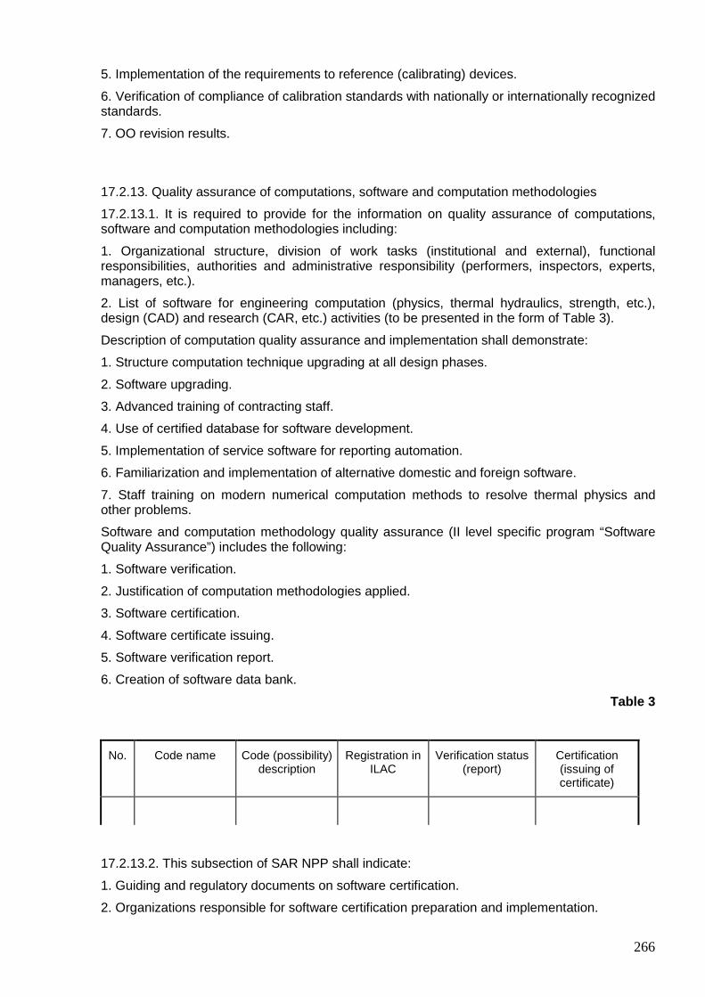
266
5. Implementation of the requirements to reference (calibrating) devices.
6. Verification of compliance of calibration standards with nationally or internationally recognized standards.
7. OO revision results.
17.2.13. Quality assurance of computations, software and computation methodologies
17.2.13.1. It is required to provide for the information on quality assurance of computations, software and computation methodologies including:
1. Organizational structure, division of work tasks (institutional and external), functional responsibilities, authorities and administrative responsibility (performers, inspectors, experts, managers, etc.).
2. List of software for engineering computation (physics, thermal hydraulics, strength, etc.), design (CAD) and research (CAR, etc.) activities (to be presented in the form of Table 3).
Description of computation quality assurance and implementation shall demonstrate:
1. Structure computation technique upgrading at all design phases.
2. Software upgrading.
3. Advanced training of contracting staff.
4. Use of certified database for software development.
5. Implementation of service software for reporting automation.
6. Familiarization and implementation of alternative domestic and foreign software.
7. Staff training on modern numerical computation methods to resolve thermal physics and other problems.
Software and computation methodology quality assurance (II level specific program “Software Quality Assurance”) includes the following:
1. Software verification.
2. Justification of computation methodologies applied.
3. Software certification.
4. Software certificate issuing.
5. Software verification report.
6. Creation of software data bank.
Table 3
No. Code name Code (possibility) description
Registration in ILAC
Verification status (report)
Certification (issuing of certificate)
17.2.13.2. This subsection of SAR NPP shall indicate:
1. Guiding and regulatory documents on software certification.
2. Organizations responsible for software certification preparation and implementation.
267
3. Software certification procedure.
4. Procedure for certificate preparation.
5. Passport data.
6. Content of software verification report.
7. Procedure for software preparation and registration in ILAC.
The information is assumed to be presented as references to procedural documents and reports.
17.2.14. Equipment handling, storage and transportation
This subsection of SAR NPP shall contain the information on the results of general and specific quality assurance program implementation to meet the requirements for equipment handling, conservation, storage, decontamination, packaging and transportation including:
1. Control of compliance with supplier instructions and TC on equipment handling, storage and transportation.
2. Availability of procedures to monitor equipment handling, storage and transportation.
3. Availability of monitoring methods during equipment handling, storage and transportation.
4. Equipment verification before shipment.
5. Results of OO inspections and audits.
17.2.15. Reliability assurance
The general objective of this subsection is to demonstrate efficiency of the system and equipment reliability assurance measures.
List of NPP equipment which reliability assurance requirements are applied to shall be presented.
Indicate leading organization as well as subcontractors involved in reliability assurance activity specified in QAP.
Interaction procedure and organizational structure of the organizations involved shall be presented.
17.2.16. Equipment examination, testing and operational state
This subsection of SAR NPP shall contain the information on development and implementation of the procedures establishing equipment verifications, testing and operation during manufacturing, assembling and testing. This includes a description of measures provided for to specify the use of trademarks, labels, roadmaps, stamps, etc. and methodology to apply such measures.
Describe measures to monitor sequence of safety important operations such as equipment testing, examination and etc.
It is required to describe measures providing for indication of equipment and mechanism’s working position to prevent unauthorized actuation (for example, valves, switches).
Provide for measures for record-keeping of non-compliances (deviations).

268
17.2.17. Non-compliance control
17.2.17.1. This subsection shall contain a procedure to record violations of the requirements for work (services) and (or) equipment quality (design and manufacture faults, equipment defects and failures, operational events, personnel errors etc.).
The information on procedure for data collection and processing system for violations, causes, formalization of information exchange and cause analysis shall be presented.
It is required to describe the procedure for communicating discrepancies and corrective measures to relevant organizations and Gosatomnadzor of Russia.
This subsection shall also contain the information on recorded cases of decision-making for detected discrepancies, monitoring results of quality assurance services and analysis of detected violations by Operating Organization.
17.2.17.2. Describe procedures (or provide references) to identify, keep records and notify relevant organizations on deviations detected regarding materials, equipment and components. Provide for a description on administrative responsibilities of quality assurance services and other organizations involved in non-compliance control.
17.2.17.3. Provide for the information on decision-making with regard to detected non-compliances and monitoring results.
17.2.17.4. It is required to provide information on OO deviations’ analysis.
17.2.18. Corrective measures
This subsection of SAR NPP is required to describe measures facilitating record-keeping of corrective actions since factors negatively affecting the quality such as damage, failure, defects, deviations as well as other non-conformances have been determined.
Program for corrective measures shall be described and its efficiency shall be demonstrated indicating the role of quality assurance services. It is required to pay attention to non-conformance causes.
Provide for the information justifying that main causes, corrective measures undertaken to prevent such causes are recorded and reported to the Administration and Operating Organization for consideration and analysis. Describe the basic corrective measures on the basis of general and specific NPP QAPs by the moment of SAR NPP submission. SAR NPP is to contain basic corrective measures considering the results of NPP QAP (О) and specific QAPs by the moment of SAR NPP submission.
17.2.19. Quality assurance documentation (records)
17.2.19.1. Documentation on QAP implementation shall be described in this subsection of SAR NPP to reflect factual data on quality including the results of verifications, inspections, audits, testing, material evaluation, process and operation indicators as well as related information such as personnel qualification, methodological, regulatory guidelines. Procedure to monitor data streams between the organizations, enterprises and their units shall be incorporated.
17.2.19.2. This subsection shall contain a description of document control procedure providing for:
1. List of individuals and organizations responsible for document preparation, approval and issuing.
2. List of relevant documents to be used at various phases.
3. Coordination procedure and document control specifying work sharing (internal and external).
4. Confirmation of actual document turn-over correctness, of updated version receipt, return of invalid documents or relevant marking to prevent occasional use.

269
This subsection shall contain:
• procedure to control quality assurance information associated with NPP quality assurance at Operating Organization and NPP;
• availability and implementation of the procedure for accounting, keeping and provision of the documentation which shall be maintained in accordance with written procedures;
• information on applicable procedures to develop and maintain quality assurance documentation (registered quality-related data priorities ranged by importance attached, identification, collection, indexing, access, library creation, storage, record-keeping, and destruction including the results of inspections, testing, process verification, evaluation of equipment, components and materials supplied);
• description of NPP QAP implementation accounting system which shall include inter alia drafting procedure for:
17.2.19.3. This subsection of SAR NPP shall contain a description of QAP implementation reporting system which shall include, inter alia:
1. Drafting of review reports on document involvement, product quality, quality-related costs, reliability assessment and etc. 2. Preparation of annual reports on product quality for a certain period of time.
3. Development of annual reports of designer supervision results during manufacture, assembling, testing and operation.
17.2.20. Audits
17.2.20.1. SAR NPP sub-section shall describe measures providing for audits aimed to determine QAP actual status and its effectiveness.
SAR NPP shall contain QAP revision procedure which provides for, inter alia:
1. Availability of basic provisions, methodologies, procedures and instructions to conduct work which ensure quality during design, manufacture, construction and SAO.
2. Determination of relevant information (input design data and documents).
3. Relation to design, engineering, manufacture, construction, assembling and testing processes.
4. Incorporation of quality requirements to design and engineering documentation.
5. Efficient control over documentation development and modifications thereof.
Inspection and revision system shall be described with respect to both external (done by the Operating Organization and Gosatomnadzor of Russia) and internal (performed by an organization implementing QAP) audits.
Audits carried out by the Operating Organization are envisaged by “General Quality Assurance Program” schedules.

270
CHAPTER 18. DECOMMISSIONING
18.1. Decommissioning concept
There shall be a description of the concept and sequence of activities of the power unit decommissioning and of how radiation safety is to be ensured during implementation of these activities.
Demonstrate how it is envisaged to ensure radiation safety of personnel, population and the environment (after nuclear fuel being unloaded) during moth-balling phase (monitored storage), disposal phase (site limited use) and power unit elimination phase (site unlimited use). The following measures shall be carried out: development of decommissioning programs not later than five years prior to power unit design lifetime expiry; comprehensive surveillance including NPP power unit radiation study; preparation of safety analysis report under NPP power unit decommissioning.
It is required to demonstrate how to ensure RW minimum quantity (volume) and reduction of dose burden to personnel and population in accordance with ALARA principle; how to arrive at reduction of radioactive product release to the environment up to minimum possible level during all decommissioning phases.
18.2. Radiation sources
To ensure radiation safety under decommissioning as well as to reduce RW quantity, content of chemical elements (basic, additional and traces within 1.0∗10-2 – 1.0∗10-5 of % mass) of reactor internals materials, reactor vessel (carbon steel and special steel), protection’s concrete (standard and special) and other constructions shall be provided for. It shall be taken into account that RW quantity generated under equipment and protective construction dismantling, equipment and compartment decontamination as well as ionizing radiation dose received by personnel during such component dismantling and RW storage and disposal is determined mainly by long-lived radionuclides contained as traces. Half-life of such radionuclides varies from several to hundreds thousand years, for example: tritium; carbon-14; iron-55,59; chrome-51; manganese-54,56; cobalt-58,60; nickel-59,63; zinc-65; molybdenum-93; niobium-94; technetium-99; argentum-108m; europium-152,154 and etc. As far as concrete (standard and special) is concerned a certain contribution is made by, in addition to the above mentioned chlorine-36, calcium-41, barium-133, samarium-151 and some others.
It is required to indicate analysis results for two possible options to reduce radionuclide quantity in steel structures by neutron absorption in RI materials:
1. Replacement of alloys with high concentration of cobalt with cobalt low content alloys or with alloys which do not contain cobalt.
2. Reduction of cobalt, argentum, niobium and nickel concentration in structural materials.
Limited involvement or complete elimination of serpentinites, chromites, magnetites in protective constructions due to high concentration of cobalt and iron should be analyzed and their application should be justified.
To reduce concrete induced activity Portland (cement) flow rate shall be maintained as minimum possible. Flow rate reduction can be achieved by using special additives. Data justifying that impact to radiation safety by Portland (cement) application is minimized shall be demonstrated.
Lithium concentration in the reactor protective structures shall be evaluated as it generates tritium when neutrons are absorbed. Tritium concentration, as a rule, is small comparing with other radionuclides contained in such structures. Additives containing elements with large cross-section for neutron absorption, small half-life of generated radionuclides or low ionizing radiation released or low radiation energy reduce radiation consequences of neutron activation.
271
It is required to provide computation data for equipment and protective constructions material activity as well as their radiation fields, evaluation of RW total quantity and its isotopic composition as well as to determine amount of materials of unlimited use (recycled) to be disposed of. Computations shall be made for activating neutron energies within total reactor spectrum with break-down to groups corresponding to the groups of preliminary computation of neutron flux density. Computations obtained for neutron activation as well as related dose rates shall include time dependencies after NPP power unit shutdown. Certified software shall be used for computation.
Basing on the experience with regard to similar power unit decommissioning and radiation survey, preliminary assessments shall be presented for contamination of power unit equipment, protective constructions and compartments by such radionuclides as sodium-22, potassium-40, manganese-54, cobalt-57,58,60, zinc-65, strontium-90, zirconium-95, niobium-95, ruthenium-106+rodium-106, argentum-110m, cezium-134,137, cerium-144, etc.
On the basis of proposed technology for metal and material cutting and destruction as well as of data on specific equipment used for such purposes, assessments on quantity and disperse composition of aerosols to be generated during equipment and structures dismantling shall be incorporated.
18.3. Radiation monitoring
Requirements to radiometric (spectrometric) and dosimetry monitoring scope shall be developed on the basis of the analysis of ionizing radiation sources and aerosol characteristics. It is required to demonstrate that radiation monitoring system proposed meets the requirements specified below and is serviceable after power unit shutdown within the entire decommissioning period.
1. It shall be demonstrated that the monitoring system ensures the following measurements:
• material activity (low, medium and high level) and gamma-radiation dose rate within the range of 0 - 100 R/h;
• gamma-radiation dose rate of separate units of reactor internals, vessel, etc. and components thereof during dismantling, sorting and transportation up to 1,000 R/h (inside reactor internals – 100,000 R/h;
• surface beta-contamination of the equipment and compartments within 0 to 100,000 beta-particle/cm2∗min;
• specific volume activity of aerosol in the air within 1.0∗10-13 to 1.0∗10-10 Ci/l;
• specific volume activity of aerosol in the ventilation duct within 1.0∗10-14 to 1.0∗10-10 Ci/l;
The range of gamma-quantum (photon) energies measured shall be within 0.015 - 3 MeV.
2. It is required to demonstrate that external dosimetry ensures monitoring of radionuclide groups which are generated under decommissioning and released to the environment, in particular of those with:
• half-life of less than 10 years: calcium-45, chromium-51, manganese-54, iron-55,59, cobalt-60, zinc-65, argentum-110m, cesium-134, europium-154;
• half-life of 10-100 years: tritium, nickel-63, cesium-137, europium-152;
• half-life of more than 100 years: carbon-14, chlorine-36, calcium-41, nickel-59, niobium-94, iodine-129.
18.4. Materials of unlimited usage (recycled materi als)
Materials of unlimited usage i.e. such materials where radionuclide content is below permissible level shall be listed. According to the IAEA (there are no Russian standards available yet) it
272
amounts to 100-1,000 Bq/kg (3.0∗10-9 – 3.0∗10-8 Ci/kg). Should they be involved natural background is increased only by 1-10%.
NPP SAR shall contain data on computation and estimation of recycled material quantity which may be generated under decommissioning. In some cases the amount of such materials may be determined on the basis of radiation survey data.
It is required to demonstrate how the design meets the requirements to outlet radiation monitoring of recycled materials.
18.5. Decommissioning measures, systems and equipme nt
Demonstrate how the requirements, the compliance with which facilitates dismantling, to protective constructions are taken into account in the design and analyze their efficiency. These requirements include the following:
1. Shaping of protective structure fragments to segregate its activated part by induced activity level (high, medium, low) as well as by limited and unlimited application; 2. Make radiation protection of process equipment (reactor primary circuit and etc.) as a module providing for all strength characteristics of shielding structure;
3. Development of protective structure module which provides for the possibility to divide it into contaminated and non-contaminated areas.
4. Application of special leaktight coatings (one-, two or multilayer) to reduce contamination of concrete structures by radionuclides as well as selection of concrete components to minimize radionuclide penetration into concrete considering sorption capacities of such radionuclides.
5. Use of ceiling and wall sliding panels to make an embrasure, which ease the access to radioactive equipment and its dismantling. Possibility to use transportable shielding (“shady” shielding) to reduce dose burden to personnel during dismantling.
Special compartments for recovery of radioactively contaminated equipment, its handling, waste conditioning and recycled material management (cementation, re-melting and etc.) shall be available.
Robotics and manipulators shall be provided for handling high level RadW and contaminated equipment. The possibility for transportation thereof shall be envisaged (embrasures, tracks and etc.) as well.
It shall be determined whether the capacity of regular ventilation systems of NPP power unit is sufficient for full-scope dismantling or additional ventilation systems are required. Attention shall be given to aerosol dispersion/dismantling technology dependency as aerosol particle size determines the choice of filters and other protective barriers.
Measures to ensure radiation safety during NPP site recovery operations (soil decontamination methods or pollution localization: wash-out, soil removal, collecting and etc.) shall be considered.