supplement a to operating manual emi test receiver espi3
TRANSCRIPT

1142.8142.12 A E-4
Supplement Ato Operating Manual
EMI Test Receiver ESPI3 and ESPI7(Firmware Version 1.72)
Dear Customer,
As far as the functionality of ESPI is concerned, the following new and modified functions are not yetdescribed in the operating manual.
• Automatic final measurement with THRESHOLD SCAN (page A)
• New status messages (page E)
• Number of sweep points selectable (page F)
• Linear dB scaling (page G)
• Support for Multi Carrier Channel Power measurements (page I)
• Trigger line remains on screen after leaving the TRIG menu (page Z)
• Extended IEC/IEEE bus command (page AA)
• Extended # of frequency points (200 now!) with function SENSe:LIST (page EE)
Automatic Final Measurement with THRESHOLD SCAN
The interference spectrum is first pre-analyzed in a fast prescan to optimize the duration of themeasurement. If the measured level exceeds a limit line, or violates a margin defined for this line, thetime-consuming final measurement is performed. The final measurement is, therefore, carried out onlyfor a reduced number of frequencies of interest. For this measurement, each scan trace to be taken intoaccount has to be assigned a limit line, and the limit line and the limit check function have to beactivated in the LIMIT LINE menu.
The prescan is interrupted immediately for each final measurement to be performed, i.e. the finalmeasurement immediately follows the prescan measurement. In the case of drifting or fluctuatinginterferers, this increases the probability that the signal of interest will be reliably detected in the finalmeasurement.
If the narrowband/broadband discrimination function is activated (NB/BB DISCR softkey), the receiverautomatically selects the detector to use in the final measurement. To this end, the receiver comparesthe positive and the negative peak value obtained in the prescan. If the difference between the twovalues exceeds a user-selected threshold, a broadband interferer is assumed, and the quasi-peakdetector is used in the final measurement. If the difference falls below this threshold, a narrowbandinterferer is assumed, and the average detector is used in the final measurement. (The receiverautomatically determines the positive and the negative peak value during the prescan.)
The value obtained in the final measurement is added to the peak list, where it replaces the result of theprescan. With NO OF PEAKS, the maximum number of peak values to be included in the list can bedefined. If this number is attained, the prescan will be continued, but no further final measurements willbe performed.
1142.8142.12 B E-4
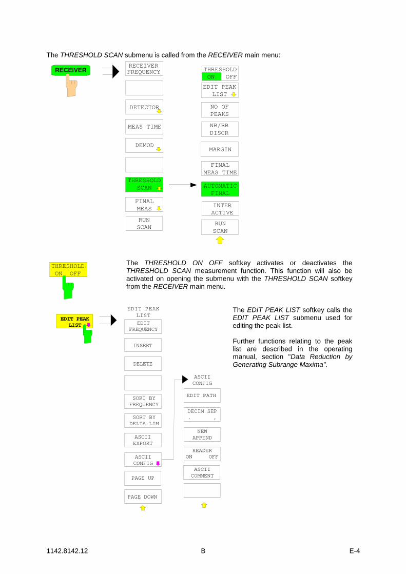
The THRESHOLD SCAN submenu is called from the RECEIVER main menu:
DETECTOR
RECEIVERFREQUENCY
MEAS TIME
RECEIVER
DEMOD
RUNSCAN
FINALMEAS
THRESHOLDSCAN
EDIT PEAKLIST
NO OFPEAKS
FINALMEAS TIME
MARGIN
NB/BBDISCR
RUNSCAN
THRESHOLDON OFF
INTERACTIVE
AUTOMATICFINAL
THRESHOLDON OFF
The THRESHOLD ON OFF softkey activates or deactivates theTHRESHOLD SCAN measurement function. This function will also beactivated on opening the submenu with the THRESHOLD SCAN softkeyfrom the RECEIVER main menu.
EDIT PATH
DECIM SEP. ,
NEWAPPEND
HEADERON OFF
ASCIICOMMENT
EDIT PEAKLIST
EDIT PEAKLIST
EDITFREQUENCY
INSERT
DELETE
SORT BYFREQUENCY
SORT BYDELTA LIM
ASCIICONFIG
ASCIIEXPORT
ASCIICONFIG
PAGE UP
PAGE DOWN
The EDIT PEAK LIST softkey calls theEDIT PEAK LIST submenu used forediting the peak list.
Further functions relating to the peaklist are described in the operatingmanual, section "Data Reduction byGenerating Subrange Maxima".
1142.8142.12 C E-4
NO OFPEAKS
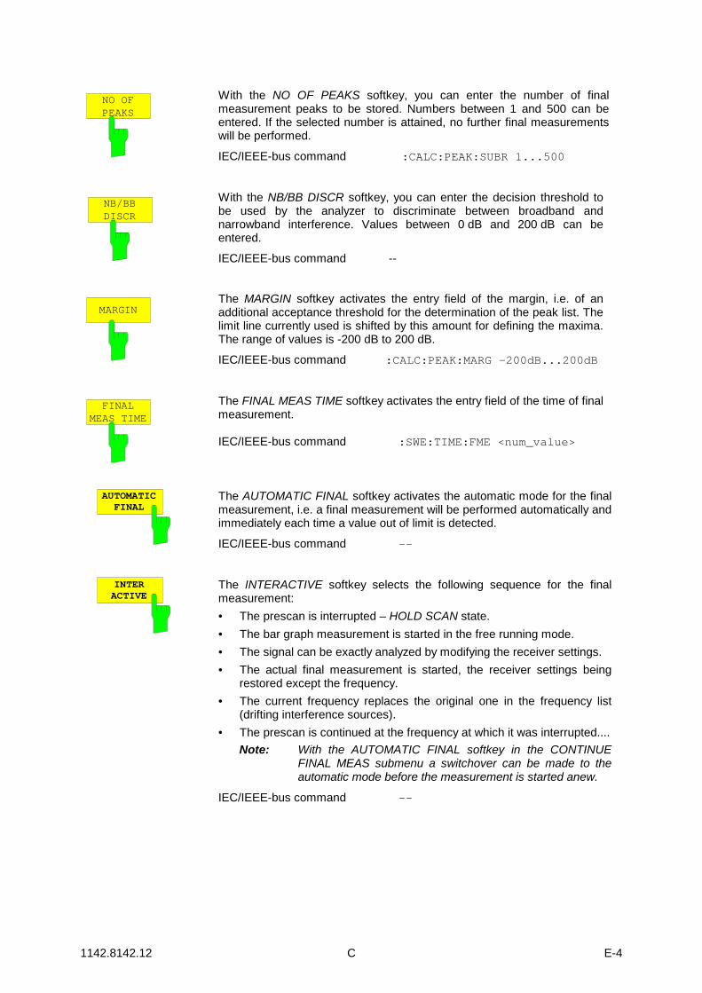
With the NO OF PEAKS softkey, you can enter the number of finalmeasurement peaks to be stored. Numbers between 1 and 500 can beentered. If the selected number is attained, no further final measurementswill be performed.
IEC/IEEE-bus command :CALC:PEAK:SUBR 1...500
NB/BBDISCR
With the NB/BB DISCR softkey, you can enter the decision threshold tobe used by the analyzer to discriminate between broadband andnarrowband interference. Values between 0 dB and 200 dB can beentered.
IEC/IEEE-bus command --
MARGINThe MARGIN softkey activates the entry field of the margin, i.e. of anadditional acceptance threshold for the determination of the peak list. Thelimit line currently used is shifted by this amount for defining the maxima.The range of values is -200 dB to 200 dB.
IEC/IEEE-bus command :CALC:PEAK:MARG –200dB...200dB
FINALMEAS TIME
The FINAL MEAS TIME softkey activates the entry field of the time of finalmeasurement.
IEC/IEEE-bus command :SWE:TIME:FME <num_value>
AUTOMATICFINAL
The AUTOMATIC FINAL softkey activates the automatic mode for the finalmeasurement, i.e. a final measurement will be performed automatically andimmediately each time a value out of limit is detected.
IEC/IEEE-bus command --
INTERACTIVE
The INTERACTIVE softkey selects the following sequence for the finalmeasurement:• The prescan is interrupted – HOLD SCAN state.• The bar graph measurement is started in the free running mode.• The signal can be exactly analyzed by modifying the receiver settings.• The actual final measurement is started, the receiver settings being
restored except the frequency.• The current frequency replaces the original one in the frequency list
(drifting interference sources).• The prescan is continued at the frequency at which it was interrupted....
Note: With the AUTOMATIC FINAL softkey in the CONTINUEFINAL MEAS submenu a switchover can be made to theautomatic mode before the measurement is started anew.
IEC/IEEE-bus command --
1142.8142.12 D E-4
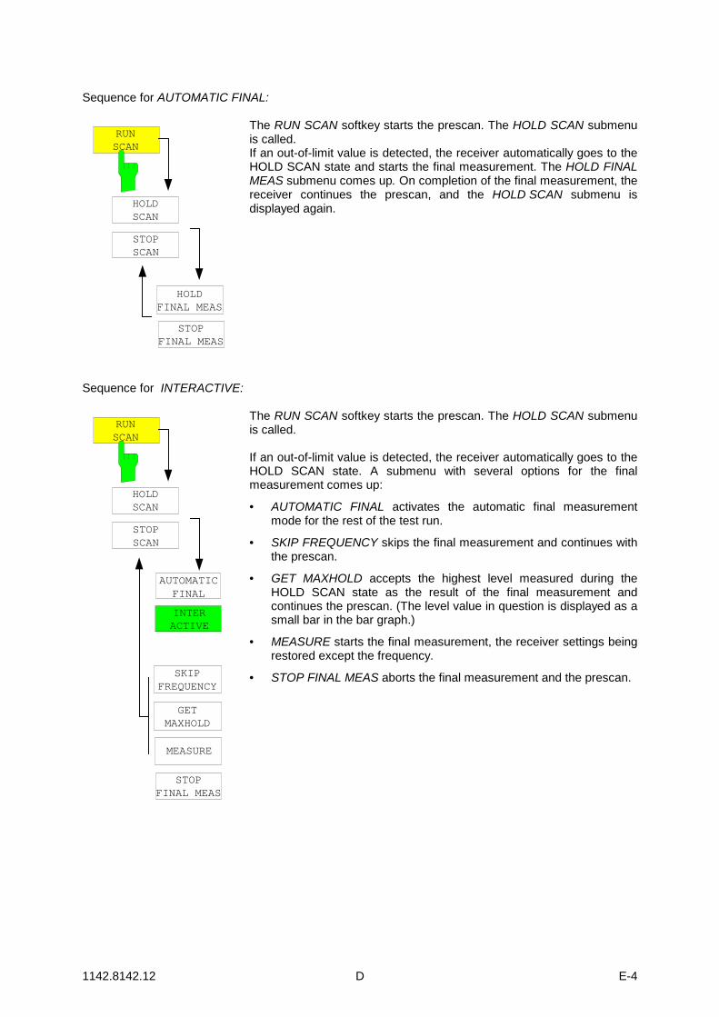
Sequence for AUTOMATIC FINAL:
RUNSCAN
HOLDSCAN
STOPSCAN
STOPFINAL MEAS
HOLDFINAL MEAS
The RUN SCAN softkey starts the prescan. The HOLD SCAN submenuis called.If an out-of-limit value is detected, the receiver automatically goes to theHOLD SCAN state and starts the final measurement. The HOLD FINALMEAS submenu comes up. On completion of the final measurement, thereceiver continues the prescan, and the HOLD SCAN submenu isdisplayed again.
Sequence for INTERACTIVE:
RUNSCAN
HOLDSCAN
STOPSCAN
STOPFINAL MEAS
SKIPFREQUENCY
AUTOMATICFINAL
INTERACTIVE
GETMAXHOLD
MEASURE
The RUN SCAN softkey starts the prescan. The HOLD SCAN submenuis called.
If an out-of-limit value is detected, the receiver automatically goes to theHOLD SCAN state. A submenu with several options for the finalmeasurement comes up:
• AUTOMATIC FINAL activates the automatic final measurementmode for the rest of the test run.
• SKIP FREQUENCY skips the final measurement and continues withthe prescan.
• GET MAXHOLD accepts the highest level measured during theHOLD SCAN state as the result of the final measurement andcontinues the prescan. (The level value in question is displayed as asmall bar in the bar graph.)
• MEASURE starts the final measurement, the receiver settings beingrestored except the frequency.
• STOP FINAL MEAS aborts the final measurement and the prescan.

1142.8142.12 E E-4
The table shows a peak list:
Trace1: 014QPEDIT PEAK LIST (Final Measurement Results)
FREQUENCY LEVEL dBpT1 Average2 Average1 Quasi Peak2 Average1 Quasi Peak2 Average1 Quasi Peak2 Average1 Quasi Peak2 Average1 Quasi Peak2 Average2 Average2 Average2 Average1 Quasi Peak2 Average1 Quasi Peak2 Average2 Average
TRACE3: ---Trace2: 014AV
DELTA LIMIT dB80.0000 MHz89.4800 MHz98.5200 MHz98.5200 MHz
100.7200 MHz102.3200 MHz113.2400 MHz116.9200 MHz125.8800 MHz125.8800 MHz138.4800 MHz138.4800 MHz144.0400 MHz167.0400 MHz176.2400 MHz200.4800 MHz200.4800 MHz210.2800 MHz226.5600 MHz230.0000 MHz
29.9935.6449.9448.3255.3350.8642.5044.4454.9153.8641.8339.3840.7744.8246.5650.9348.2758.7159.0746.90
-9.25-4.09-0.228.155.07
10.53-8.263.533.68
12.64-9.81-2.25-1.042.373.87
-2.315.025.25
15.293.05
TRACE
In the THRESHOLD SCAN mode, with the NB/BB DISCR function active, the receiver automaticallyselects the detector to be used in the final measurement on the basis of the results obtained in theprescan.
New Status Messages/Trace Info
Note: Status message MSG is omitted
#SMPL "#SMPL" indicates that the relation Span / RBW is higher than 125 whilethe RMS detector is activated. In this case a stable signal evaluation isno longer possible due to an insufficient number of A/D convertersamples.
reduce span or increase RBW
Trace-Info: Every active measurement curve (trace ≠ BLANK) is allocated traceinformation of two or three lines at the left of the diagram. The traceinformation has the same color as the measurement curve.The information on the currently selected trace is displayed ininverse video (see TRACE - SELECT TRACE softkey).
1142.8142.12 F E-4
Number of Sweep Points Selectable
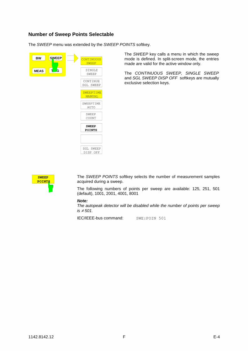
The SWEEP menu was extended by the SWEEP POINTS softkey.
SWEEP
MEAS
BW
TRIG
CONTINUOUSSWEEP
SWEEPTIMEAUTO
SWEEPCOUNT
SINGLESWEEP
SGL SWEEPDISP OFF
SWEEPTIMEMANUAL
CONTINUESGL SWEEP
SWEEPPOINTS
The SWEEP key calls a menu in which the sweepmode is defined. In split-screen mode, the entriesmade are valid for the active window only.
The CONTINUOUS SWEEP, SINGLE SWEEPand SGL SWEEP DISP OFF softkeys are mutuallyexclusive selection keys.
SWEEPPOINTS
The SWEEP POINTS softkey selects the number of measurement samplesacquired during a sweep.
The following numbers of points per sweep are available: 125, 251, 501(default), 1001, 2001, 4001, 8001
Note:The autopeak detector will be disabled while the number of points per sweepis ≠ 501.
IEC/IEEE-bus command: SWE:POIN 501

1142.8142.12 G E-4
Linear dB scaling
The AMPT menu was extended by the RANGE LINEAR submenu.
REF LEVEL
GRIDABS REL
UNIT
RF ATTENAUTO
RANGELOG 100 dB
RANGELINEAR
RANGELOG MANUAL
REF LEVELPOSITION
REF LEVELOFFSET
RF ATTENMANUAL
RF INPUT50Ω 75Ω
dBm
dBµV
dBµA
VOLT
AMPERE
WATT
dBpW
dBmV
AMPT
RANGELINEAR %
RANGELINEAR dB
RANGELINEAR
The RANGE LINEAR softkey selects linear scaling for the level display rangeof the analyzer. In addition, it opens a submenu for selecting % or dB for thescaling.When linear scaling is selected, the % scaling is first activated (see alsoRANGE LINEAR dB softkey).
IEC/IEEE-bus command: DISP:WIND:TRAC:Y:SPAC LIN
RANGELINEAR %
The RANGE LINEAR % softkey selects linearscaling in % for the level display range, i.e. thehorizontal lines are labelled in %. The grid is dividedinto decades. Markers are displayed in the selectedunit; delta markers are displayed in % referenced tothe voltage value at the position of marker 1.
IEC/IEEE-bus command:DISP:WIND:TRAC:Y:SPAC LIN
RANGELINEAR dB
The RANGE LINEAR dB softkey selects linearscaling in dB for the level display range, i.e. thehorizontal lines are labelled in dB.Markers are displayed in the selected unit; deltamarkers are displayed in dB referenced to thepower value at the position of marker 1.
IEC/IEEE-bus command:DISP:WIND:TRAC:Y:SPAC LDB

1142.8142.12 H E-4
Modified softkey menu MKR->
In the MRK-> menus of Receiver and Analyzer mode, the softkeys NEXT PEAK, NEXT PEAK LEFT,NEXT PEAK RIGHT, NEXT MIN, NEXT MIN LEFT, NEXT MIN RIGHT were re-ordered for easieroperation.Receiver Mode:
NEXT PEAK
PEAKEXCURSION
MKR MKR
SELECTMARKER
SEARCHLIMITS
MRK->TRACE
AMPLSPAN
PEAK MIN
NEXT MINRIGHT
FCTN
MKR -> CFSTEPSIZE
NEXT PEAKLEFT
NEXT PEAKRIGHT
NEXT MINLEFT
ADD TOPEAK LIST
TUNE TOMARKER
NEXTMIN
SETTINGSCOUPLED
RIGHTLIMIT
LEFTLIMIT
THRESHOLD
SEARCH LIMOFF
MARKERTRACK
Analyzer Mode:
NEXT PEAK
REF LEVEL=MKR LVL
PEAKEXCURSION
MKR MKR
SELECTMARKER
CENTER=MKR FREQ
SEARCHLIMITS
MRK->TRACE
AMPLSPAN
PEAK MIN
NEXT MINRIGHT
FCTN
MKR -> CFSTEPSIZE
EXCLUDELO
RIGHTLIMIT
LEFTLIMIT
THRESHOLD
SEARCH LIMOFF
NEXT PEAKLEFT
NEXT PEAKRIGHT
NEXT MINLEFT
NEXT MIN
1142.8142.12 I E-4
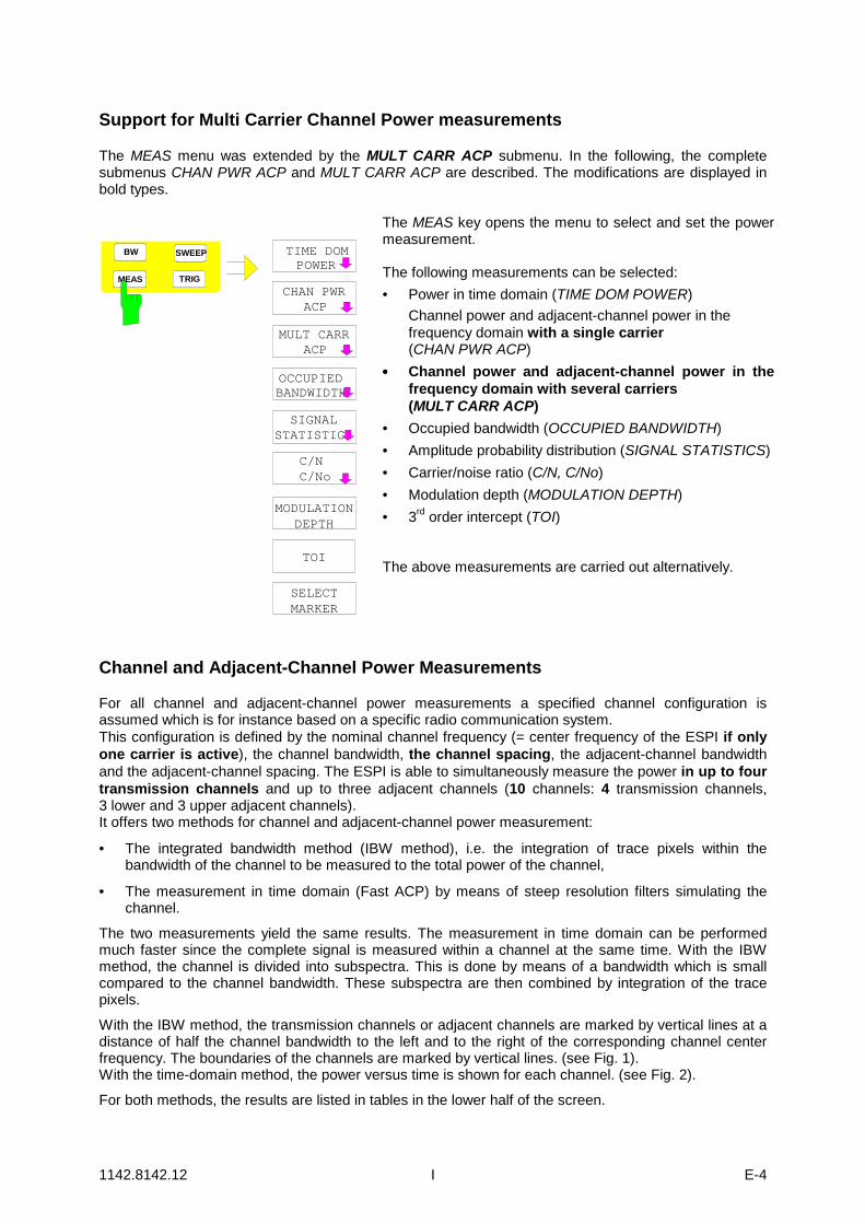
Support for Multi Carrier Channel Power measurements
The MEAS menu was extended by the MULT CARR ACP submenu. In the following, the completesubmenus CHAN PWR ACP and MULT CARR ACP are described. The modifications are displayed inbold types.
SIGNALSTATISTIC
MEAS TRIG
TIME DOMPOWER
OCCUPIEDBANDWIDTH
SWEEPBW
MULT CARRACP
MODULATIONDEPTH
TOI
SELECTMARKER
C/NC/No
CHAN PWRACP
The MEAS key opens the menu to select and set the powermeasurement.
The following measurements can be selected:• Power in time domain (TIME DOM POWER)
Channel power and adjacent-channel power in thefrequency domain with a single carrier(CHAN PWR ACP)
•••• Channel power and adjacent-channel power in thefrequency domain with several carriers(MULT CARR ACP)
• Occupied bandwidth (OCCUPIED BANDWIDTH)• Amplitude probability distribution (SIGNAL STATISTICS)• Carrier/noise ratio (C/N, C/No)• Modulation depth (MODULATION DEPTH)• 3rd order intercept (TOI)
The above measurements are carried out alternatively.
Channel and Adjacent-Channel Power Measurements
For all channel and adjacent-channel power measurements a specified channel configuration isassumed which is for instance based on a specific radio communication system.This configuration is defined by the nominal channel frequency (= center frequency of the ESPI if onlyone carrier is active), the channel bandwidth, the channel spacing, the adjacent-channel bandwidthand the adjacent-channel spacing. The ESPI is able to simultaneously measure the power in up to fourtransmission channels and up to three adjacent channels (10 channels: 4 transmission channels,3 lower and 3 upper adjacent channels).It offers two methods for channel and adjacent-channel power measurement:
• The integrated bandwidth method (IBW method), i.e. the integration of trace pixels within thebandwidth of the channel to be measured to the total power of the channel,
• The measurement in time domain (Fast ACP) by means of steep resolution filters simulating thechannel.
The two measurements yield the same results. The measurement in time domain can be performedmuch faster since the complete signal is measured within a channel at the same time. With the IBWmethod, the channel is divided into subspectra. This is done by means of a bandwidth which is smallcompared to the channel bandwidth. These subspectra are then combined by integration of the tracepixels.
With the IBW method, the transmission channels or adjacent channels are marked by vertical lines at adistance of half the channel bandwidth to the left and to the right of the corresponding channel centerfrequency. The boundaries of the channels are marked by vertical lines. (see Fig. 1).With the time-domain method, the power versus time is shown for each channel. (see Fig. 2).
For both methods, the results are listed in tables in the lower half of the screen.

1142.8142.12 J E-4
The ESPI offers predefined standard settings which can be selected from a table for the commonmobile radio standards. Thus, channel configuration is performed automatically without the need toenter the corresponding parameters manually.For some standards, the channel power and the adjacent-channel power are to be weighted by meansof a root-raised cosine filter corresponding to a receive filter. This type of filtering is switched onautomatically for both methods on selecting the standard (e.g. NADC, TETRA or 3GPP W-CDMA).
Fig. 1 Screen display of adjacent-channel power measurement using the IBW method
Fig. 2 Screen display of adjacent-channel power measurement using the time-domain method
Limit values for the adjacent-channel power can be defined for the measurement. If limit checking isswitched on, a pass/fail information indicating that the power has been exceeded is displayed during themeasurement in the table in the lower half of the screen.

1142.8142.12 K E-4
Note: With the CP/ACP measurement switched on the functions SPLIT SCREEN and FULLSCREEN are inhibited.
The channel configuration is defined in the MEAS - CHAN PWR ACP or the MEAS - MULT CARR ACPmenu.
CP/ACPABS REL
SET CPREFERENCE
CP/ACPCONFIG
ADJUSTREF LVL
CP/ACPSTANDARD
NO. OFADJ CHAN
ADJ CHANBANDWIDTH
ADJ CHANSPACING
CHANNELBANDWIDTH
CHAN PWR/ HZ
CP/ACPON OFF
CHAN POWER/ACP
SWEEPTIME
SELECTTRACE
NOISE CORRON OFF
FAST ACPON OFF
ACP LIMITCHECK
EDITACP LIMIT
ADJUSTSETTINGS
NOISE CORRON OFF
FULL SIZEDIAGRAM
The CHAN PWR ACP and MULTCARR ACP softkeys activatechannel or adjacent-channelpower measurement either for asingle carrier signal (CHAN PWRACP) or for several carriersignals (MULT CARR ACP),depending on the currentmeasurement configuration. Inaddition, they open a submenufor defining the parameters forchannel power measurement.The softkey selected is shown incolor to indicate that a channelor adjacent-channel powermeasurement is active.
Note: The softkeys are availableonly for measurements inthe frequency domain(span > 0).
CP/ACPON OFF
The CP/ACP ON/OFF softkey switches calculation of the channel power oradjacent-channel power on and off.
With default settings the measurement is performed by integrating the powers atthe display points within the specified channels (IBW method).
The powers of the adjacent channels are measured either as absolute values oras relative values referenced to the power of a transmission channel. The defaultsetting is relative-value measurement (see CP/ACP ABS/REL softkey).
When multicarrier ACP measurement is activated, the number of testpoints is increased to ensure that adjacent-channel powers are measuredwith adequate accuracy.IEC/IEEE-bus commands: CALC:MARK:FUNC:POW:SEL CPOW|ACP|MCAC
CALC:MARK:FUNC:POW:RES? CPOW|ACP|MCACCALC:MARK:FUNC:POW OFF
CP/ACPSTANDARD
The CP/ACP STANDARD softkey opens a table for the selection of the settingsaccording to predefined standards. The test parameters for the channel andadjacent-channel measurements are set according to the mobile radio standard.

1142.8142.12 L E-4
ACP STANDARD
NONENADC IS136TETRAPDCPHSCDPDCDMA IS95A FWDCDMA IS95A REVCDMA IS95C Class 0 FWDCDMA IS95C Class 0 REVCDMA J-STD008 FWDCDMA J-STD008 REVCDMA IS95C Class 1 FWDCDMA IS95C Class 1 REVW-CDMA 4.096 FWDW-CDMA 4.096 REVW-CDMA 3GPP FWDW-CDMA 3GPP REVCDMA 2000 DSCDMA 2000 MC1CDMA 2000 MC3TD-SCDMA
The standards available are listed in thetable on the left.
Note: For the ESPI, the channel spacing is defined as the distance betweenthe center frequency of the adjacent channel and the center frequencyof the transmission channel. The definition of the adjacent-channelspacing in standards IS95 B and C, IS97 B and C and IS98 B and C isdifferent. These standards define the adjacent-channel spacing fromthe center of the transmission channel to the closest border of theadjacent channel. This definition is also used for the ESPI when thefollowing standard settings are selected:CDMA IS95 Class 0 FWDCDMA IS95 Class 0 REVCDMA IS95 Class 1 FWDCDMA IS95 Class 1 REV
The selection of the standard influences the following parameters:• channel spacing and adjacent-channel spacing• channel bandwidth, adjacent-channel bandwidth, and type of filtering• resolution bandwidth• video bandwidth• detector• # of adjacent channels
Trace mathematics and trace averaging are switched off.The reference level is not influenced by the selection of a standard. To achievean optimum dynamic range, the reference level has to be set in a way thatplaces the signal maximum close to the reference level without forcing anoverload message.
The default setting is CP/ACP STANDARD NONE.
IEC/IEEE-bus command: CALC:MARK:FUNC:POW:PRES <standard>

1142.8142.12 M E-4
CP/ACPCONFIG
See following section "Setting the Channel Configuration"
SET CPREFERENCE
With channel power measurement activated, the SET CP REFERENCE softkeydefines the currently measured channel power as the reference value. The referencevalue is displayed in the CH PWR REF field; the default value is 0 dBm.
In adjacent-channel power measurement with one or several carriersignals, the power is always referenced to a transmission channel, i.e. novalue is displayed for CH PWR REF.IEC/IEEE-bus command: POW:ACH:REF:AUTO ONCE
SWEEPTIME
The SWEEP TIME softkey activates the entry of the sweep time. With the RMSdetector, a longer sweep time increases the stability of the measurement results.The function of the softkey is identical to the softkey SWEEP TIME MANUAL inthe menu BW.
IEC/IEEE-bus command: SWE:TIM <value>
NOISE CORRON OFF
If the NOISE CORR ON/OFF softkey is activated, the results will be corrected bythe instrument's inherent noise, which increases the dynamic range.When the function is switched on, a reference measurement of the instrument'sinherent noise is carried out. The noise power measured is then subtracted fromthe power in the channel that is being examined.The inherent noise of the instrument depends on the selected center frequency,resolution bandwidth and level setting. Therefore, the correction function isdisabled whenever one of these parameters is changed. A disable message isdisplayed on the screen.To enable the correction function in conjunction with the changed setting, pressthe softkey once more. A new reference measurement is carried out.
IEC/IEEE-bus command: SENS:POW:NCOR ON

1142.8142.12 N E-4
FAST ACPON OFF
The FAST ACP softkey switches between the IBW method (FAST ACP OFF) andthe time domain method (FAST ACP ON).With FAST ACP ON the power measurement is performed in the different channelsin the time domain. The ESPI sets the center frequency consecutively to the differentchannel center frequencies and measures the power with the selected measurementtime (= sweep time/number of channels). The RBW filters suitable for the selectedstandard and frequency offset are automatically used (e.g. root raised cos with IS136). The list of available channel filters is included in section "Setting of Bandwidthsand Sweep Time – BW key".The RMS detector is used for obtaining correct power measurement results.Therefore this requires no software correction factors.Measured values are output as a list. The powers of the transmissionchannels are output in dBm, the powers of the adjacent channels in dBm(CP/ACP ABS) or dB (CP/ACP REL).The sweep time is selected depending on the desired reproducibility of results.Reproducibility increases with sweep time since power measurement is thenperformed over a longer time period.As a general approach, it can be assumed that approx. 500 non-correlatedmeasured values are required for a reproducibility of 0.5 dB (99% of themeasurements are within 0.5 dB of the true measured value). This holds true forwhite noise. The measured values are considered as non-correlated when theirtime interval corresponds to the reciprocal of the measured bandwidth.With IS 136 the measurement bandwidth is approx. 25 kHz, i.e. measuredvalues at an interval of 40 µs are considered as noncorrelated. A measurementtime of 20 ms is thus required per channel for 1000 measured values. This is thedefault sweep time which the ESPI sets in coupled mode. Approx. 5000measured values are required for a reproducibility of 0.1 dB (99%), i.e. themeasurement time is to be increased to 200 ms.
IEC/IEEE-bus command SENS:POW:HSP ON
FULL SIZEDIAGRAM
The FULL SIZE DIAGRAM softkey switches the diagram to full screen size.
IEC/IEEE-bus command: DISP:WIND1:SIZE LARG|SMAL
ADJUSTREF LVL
The ADJUST REF LVL softkey adjusts the reference level of the ESPI to themeasured channel power. This ensures that the settings of the RF attenuationand the reference level are optimally adjusted to the signal level withoutoverloading the ESPI or limiting the dynamic range by a too small S/N ratio.Since the measurement bandwidth for channel power measurements issignificantly lower than the signal bandwidth, the signal path may be overloadedalthough the trace is still significantly below the reference level.
IEC/IEEE-bus command: SENS:POW:ACH:PRES:RLEV
For manual setting of the test parameters different from the settings made with ADJUST SETTINGS thefollowing should be observed:

1142.8142.12 O E-4
Frequency span The frequency span must at least cover the channels to be measured plusa measurement margin of 10%.For channel power measurement, the span is 1.1 x channel bandwidth.
Note: If the frequency span is large in comparison with the channelbandwidth (or the adjacent-channel bandwidths) being examined, only afew points on the trace are available per channel. This reduces theaccuracy of the waveform calculation for the channel filter used, which hasa negative effect on the measurement accuracy.We therefore strongly recommend that the formulas mentioned be takeninto consideration when selecting the frequency span.
Resolution bandwidth (RBW)To ensure both an acceptable measurement speed and the requiredselection (to suppress spectral components outside the channel to bemeasured, especially of the adjacent channels), the resolution bandwidthmust not be selected too small or too large. As a general approach, theresolution bandwidth is to be set to values between 1% and 4% of thechannel bandwidth.A larger resolution bandwidth can be selected if the spectrum within thechannel to be measured and around it has a flat characteristic. In thestandard setting, e.g. for standard IS95A REV at an adjacent channelbandwidth of 30 kHz, a resolution bandwidth of 30 kHz is used. This yieldscorrect results since the spectrum in the neighborhood of the adjacentchannels normally has a constant level. For standard NADC/IS136 this isnot possible for example, since the spectrum of the transmit signalpenetrates into the adjacent channels and a too large resolution bandwidthcauses a too low selection of the channel filter. The adjacent-channelpower would thus be measured too high.With the exception of the IS95 CDMA standards, the ADJUST SETTINGSsoftkey sets the resolution bandwidth (RBW) as a function of the channelbandwidth:
RBW ≤ 1/40 of channel bandwidth.
The maximum possible resolution bandwidth (with respect to therequirement RBW ≤ 1/40) resulting from the available RBW steps (1, 3) isselected .
Video bandwidth (VBW) For a correct power measurement, the video signal must not be limited inbandwidth. A restricted bandwidth of the logarithmic video signal wouldcause signal averaging and thus result in a too low indication of the power(-2.51 dB at very low video bandwidths). The video bandwidth shouldtherefore be selected at least three times the resolution bandwidth.The ADJUST SETTINGS softkey sets the video bandwidth (VBW) as afunction of the channel bandwidth as follows:
VBW ≥ 3 × RBW.
The smallest possible VBW with regard to the available step size will beselected.
Detector The ADJUST SETTINGS softkey selects the RMS detector.The RMS detector is selected since it correctly indicates the powerirrespective of the characteristics of the signal to be measured. In principle,the sample detector would be possible as well. Due to the limited numberof trace pixels used to calculate the power in the channel, the sampledetector would yield less stable results. Averaging, which is oftenperformed to stabilize the measurement results, leads to a too low levelindication and should therefore be avoided. The reduction in the displayedpower depends on the number of averages and the signal characteristics inthe channel to be measured.

1142.8142.12 P E-4
Setting the Channel Configuration
MEAS - CP/ACP CONFIG submenu:
CP/ACPCONFIG
CP/ACPABS REL
NO. OFADJ CHAN
CHANNELSPACING
ACP REFSETTINGS
CHANNELBANDWIDTH
CHAN PWR/ HZ
SELECTTRACE
ACP LIMITCHECK
EDITACP LIMIT
ADJUSTSETTINGS
NO. OFTX CHAN
The CP/ACP CONFIG softkey opens a submenufor configuration of the channel power and adjacentchannel power measurement independently of theoffered standards.
The channel configuration includes the numberof channels to be measured, the channelbandwidths (CHANNEL BANDWIDTH), and thechannel spacings (CHANNEL SPACING).
Limit values can additionally be specified for theadjacent-channel power (ACP LIMIT CHECK andEDIT ACP LIMITS) which are checked forcompliance during the measurement.
NO. OFADJ CHAN
The NO. OF ADJ CHAN softkey activates the entry of thenumber ±n of adjacent channels to be considered in theadjacent-channel power measurement.Numbers from 0 to 3 can be entered.
The following measurements are performed depending on thenumber of the channels.0 Only the channel powers are measured.1 The channel powers and the power of the upper and lower
adjacent channel are measured.2 The channel powers, the power of the upper and lower
adjacent channel and of the next higher and lower channel(alternate channel 1) are measured.
3 The channel power, the power of the upper and loweradjacent channel, the power of the next higher and lowerchannel (alternate channel 1) and of the next but onehigher and lower adjacent channel (alternate channel 2)are measured.
IEC/IEEE-bus command: POW:ACH:ACP 1
NO. OFTX CHAN
The NO. OF TX CHAN softkey enables the entry of thenumber of carrier signals to be considered in channel andadjacent-channel power measurements.
Numbers from 1 to 4 can be entered.
The softkey is available only for multicarrier ACPmeasurements.
IEC/IEEE-bus command: SENS:POW:ACH:TXCH:COUN 4
1142.8142.12 Q E-4
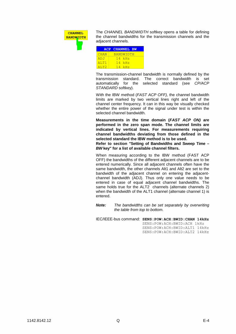
CHANNELBANDWIDTH
The CHANNEL BANDWIDTH softkey opens a table for definingthe channel bandwidths for the transmission channels and theadjacent channels.
ACP CHANNEL BWCHAN BANDWIDTHADJ 14 kHzALT1 14 kHzALT2 14 kHz
The transmission-channel bandwidth is normally defined by thetransmission standard. The correct bandwidth is setautomatically for the selected standard (see CP/ACPSTANDARD softkey).
With the IBW method (FAST ACP OFF), the channel bandwidthlimits are marked by two vertical lines right and left of thechannel center frequency. It can in this way be visually checkedwhether the entire power of the signal under test is within theselected channel bandwidth.
Measurements in the time domain (FAST ACP ON) areperformed in the zero span mode. The channel limits areindicated by vertical lines. For measurements requiringchannel bandwidths deviating from those defined in theselected standard the IBW method is to be used.Refer to section "Setting of Bandwidths and Sweep Time –BW key" for a list of available channel filters.When measuring according to the IBW method (FAST ACPOFF) the bandwidths of the different adjacent channels are to beentered numerically. Since all adjacent channels often have thesame bandwidth, the other channels Alt1 and Alt2 are set to thebandwidth of the adjacent channel on entering the adjacent-channel bandwidth (ADJ). Thus only one value needs to beentered in case of equal adjacent channel bandwidths. Thesame holds true for the ALT2 channels (alternate channels 2)when the bandwidth of the ALT1 channel (alternate channel 1) isentered.
Note: The bandwidths can be set separately by overwritingthe table from top to bottom.
IEC/IEEE-bus command: SENS:POW:ACH:BWID:CHAN 14kHzSENS:POW:ACH:BWID:ACH 1kHzSENS:POW:ACH:BWID:ALT1 14kHzSENS:POW:ACH:BWID:ALT2 14kHz

1142.8142.12 R E-4
CHANNELSPACING
The CHANNEL SPACING softkey opens a table for defining thechannel spacings.
ACP CHANNEL SPACING
CHAN SPACINGADJ 20 kHzALT1 40 kHzALT2 60 kHz
Since all the adjacent channels often have the same distance toeach other, the entry of the adjacent-channel spacing (ADJ)causes channel spacing ALT1 to be set to twice and channelspacing ALT2 to three times the adjacent-channel spacing. Thusonly one value needs to be entered in case of equal channelspacing. The same holds true for the ALT2 channels when thebandwidth of the ALT1 channel is entered.
Note: The channel spacings can be set separately byoverwriting the table from top to bottom.
IEC/IEEE-bus command: SENS:POW:ACH:SPAC:CHAN 20kHz SENS:POW:ACH:SPAC:ACH 20kHz SENS:POW:ACH:SPAC:ALT1 40kHz SENS:POW:ACH:SPAC:ALT2 60kHz
ACP REFSETTINGS
The ACP REF SETTINGS softkey opens a table for selectingthe transmission channel to which the adjacent-channelrelative power values should be referenced.
ACP REFERENCE CHANNELTX CHANNEL 1TX CHANNEL 2TX CHANNEL 3TX CHANNEL 4MIN POWER TX CHANNELMAX POWER TX CHANNELLOWEST & HIGHEST CHANNEL
TX CHANNEL 1 - 4 Selection of one of channels 1 to 4.
MIN POWERTX CHANNEL
The transmission channel with thelowest power is used as a referencechannel.
MAX POWERTX CHANNEL
The transmission channel with thehighest power is used as areference channel.
LOWEST & HIGHESTCHANNEL
The outer lefthand transmissionchannel is the reference channel forthe lower adjacent channels, theouter righthand transmissionchannel that for the upper adjacentchannels.
IEC/IEEE-bus command:SENS:POW:ACH:REF:TXCH:MAN 1SENS:POW:ACH:REF:TXCH:AUTO MIN
1142.8142.12 S E-4
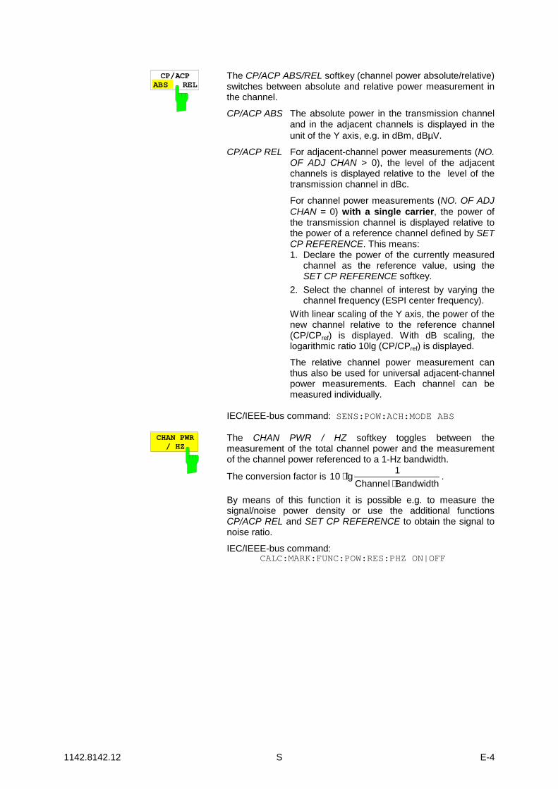
CP/ACPABS REL
The CP/ACP ABS/REL softkey (channel power absolute/relative)switches between absolute and relative power measurement inthe channel.
CP/ACP ABS The absolute power in the transmission channeland in the adjacent channels is displayed in theunit of the Y axis, e.g. in dBm, dBµV.
CP/ACP REL For adjacent-channel power measurements (NO.OF ADJ CHAN > 0), the level of the adjacentchannels is displayed relative to the level of thetransmission channel in dBc.
For channel power measurements (NO. OF ADJCHAN = 0) with a single carrier, the power ofthe transmission channel is displayed relative tothe power of a reference channel defined by SETCP REFERENCE. This means:1. Declare the power of the currently measured
channel as the reference value, using theSET CP REFERENCE softkey.
2. Select the channel of interest by varying thechannel frequency (ESPI center frequency).
With linear scaling of the Y axis, the power of thenew channel relative to the reference channel(CP/CPref) is displayed. With dB scaling, thelogarithmic ratio 10lg (CP/CPref) is displayed.
The relative channel power measurement canthus also be used for universal adjacent-channelpower measurements. Each channel can bemeasured individually.
IEC/IEEE-bus command: SENS:POW:ACH:MODE ABS
CHAN PWR/ HZ
The CHAN PWR / HZ softkey toggles between themeasurement of the total channel power and the measurementof the channel power referenced to a 1-Hz bandwidth.
The conversion factor is 10 lg 1Channel Bandwidth
⋅⋅
.
By means of this function it is possible e.g. to measure thesignal/noise power density or use the additional functionsCP/ACP REL and SET CP REFERENCE to obtain the signal tonoise ratio.
IEC/IEEE-bus command:CALC:MARK:FUNC:POW:RES:PHZ ON|OFF

1142.8142.12 T E-4
ADJUSTSETTINGS
The ADJUST SETTINGS softkey automatically optimizes theinstrument settings for the selected power measurement (seebelow).All instrument settings relevant for a power measurement withina specific frequency range (channel bandwidth) are optimized forthe selected channel configuration (channel bandwidth, channelspacing):• Frequency span:
The frequency span should cover at least all channels to beconsidered in a measurement.
For channel power measurements, the frequency span is setas follows:(No. of transmission channels - 1) × × × × transmissionchannel spacing + 2 x transmission channel bandwidth +measurement margin
For adjacent-channel power measurements,the frequency span is set as a function of the number oftransmission channels, the transmission channelspacing, the adjacent-channel spacing, and thebandwidth of one of adjacent-channels ADJ, ALT1 orALT2, whichever is furthest away from the transmissionchannels:
(No. of transmission channels - 1) × × × × transmissionchannel spacing + 2 × (× (× (× (adjacent-channel spacing +adjacent-channel bandwidth) + measurement marginThe measurement margin is approx. 10% of the valueobtained by adding the channel spacing and the channelbandwidth.
• Resolution bandwidth RBW ≤ 1/40 of channel bandwidth• Video bandwidth VBW ≥ 3 × RBW• Detector RMS detector
Trace math and trace averaging functions are switched off.The reference level is not influenced by ADJUST SETTINGS. Itcan be separately adjusted with ADJUST REF LVL.
The adjustment is carried out only once; if necessary, theinstrument settings can be changed later.
IEC/IEEE-bus command:SENS:POW:ACH:PRES ACP|CPOW|MCAC|OBW

1142.8142.12 U E-4
ACP LIMITCHECK
The ACP LIMIT CHECK softkey switches the limit check for theACP measurement on and off.
IEC/IEEE-bus command: CALC:LIM:ACP ONCALC:LIM:ACP:ACH:RES?CALC:LIM:ACP:ALT:RES?
EDITACP LIMITS
The EDIT ACP LIMITS softkey opens a table for defining thelimits for the ACP measurement.
The following rules apply for the limits:
• A separate limit can be defined for each adjacent channel.The limit applies to both the upper and the lower adjacentchannel.
• A relative and/or absolute limit can be defined. The check ofboth limit values can be activated independently.
• The ESPI checks adherence to the limits irrespective ofwhether the limits are absolute or relative or whether themeasurement is carried out with absolute or relative levels. Ifboth limits are active and if the higher of both limit values isexceeded, the measured value is marked accordingly.
Note: Measured values exceeding the limit are marked by apreceding asterisk.
IEC/IEEE-bus command:CALC:LIM:ACP ONCALC:LIM:ACP:ACH 0dB,0dBCALC:LIM:ACP:ACH:STAT ONCALC:LIM:ACP:ACH:ABS –10dBm,-10dBmCALC:LIM:ACP:ACH:ABS:STAT ONCALC:LIM:ACP:ALT1 0dB,0dBCALC:LIM:ACP:ALT1:STAT ONCALC:LIM:ACP:ALT1:ABS –10dBm,-10dBmCALC:LIM:ACP:ALT1:ABS:STAT ONCALC:LIM:ACP:ALT2 0dB,0dBCALC:LIM:ACP:ALT2:STAT ONCALC:LIM:ACP:ALT2:ABS –10dBm,-10dBmCALC:LIM:ACP:ALT2:ABS:STAT ON
SELECTTRACE
The SELECT TRACE softkey selects the trace on which theCP/ACP measurement is to be performed. Only activated tracescan be selected, i.e. traces not set to BLANK.
IEC/IEEE-bus command: SENS:POW:TRAC 1

1142.8142.12 V E-4
Examples:
1. Measurement of adjacent-channel power for a specific standard:The adjacent-channel power is to be measured for a signal at 800 MHz with 0 dBm level in line withIS136.
[PRESET] Set the ESPI to the default setting.
[FREQ: CENTER: 800 MHz] Set the center frequency to 800 MHz.
[AMPT: 0 dBm] Set the reference level to 0 dBm.
[MEAS] Call the menu for the measurement functions.
[CHAN PWR / ACP] Select the channel and adjacent-channel power measurement function.The measurement is performed with the default settings or a previouslydefined setting. The submenu for setting the desired new configurationis opened.
[CP/ACP STANDARD:select IS136: ENTER] Select the NADC (IS136) standard.
[CP/ACP CONFIG] Call the submenu for configuration of the adjacent-channel powermeasurement.
[NO. OF ADJ CHAN:2 ENTER] Select two adjacent channels for the measurement, i.e. the adjacent
channel and the alternate channel are measured.
[ADJUST SETTINGS] Set the optimum span, resolution bandwidth (RBW), video bandwidth(VBW) and detector automatically for the measurement. The absolutechannel power and the relative power of the adjacent channels aredisplayed on the screen.
PREVChange to the main menu for channel power measurement.
[ADJUST REF LVL] Set the reference level equal to the channel power measured.
2. Measurement with user-specific channel configuration:
Measurement of the adjacent-channel power ratio (ACPR) of an IS95 CDMA signal at 800 MHz, level0 dBm. Similar to example 1, the setting can be simplified by using CP/ACP STANDARD.[PRESET] Set the ESPI to the default setting.[FREQ: CENTER: 800 MHz] Set the center frequency to 800 MHz.[AMPT: 0 dBm] Set the reference level to 0 dBm.[MEAS] Call the menu for the measurement functions.[CHAN PWR / ACP] Select the channel and adjacent-channel power measurement function.
The measurement is carried out with the default settings or a previouslydefined setting. The submenu for setting the desired new configurationis opened.
[CP/ACP CONFIG] Call the submenu for defining the channel configuration.[NO. OF ADJ CHAN:2 ENTER] Select two adjacent channels for the measurement, i.e. the adjacent
channel and the alternate channel are measured.

1142.8142.12 W E-4
[CHANNEL BANDWIDTH:
1.23 MHz: : 30 kHz] Set the channel bandwidth to 1.23 MHz in accordance with IS 95.Set the adjacent-channel bandwidth to 30 kHz.TX/ACP CHANNEL BW
CHAN BANDWIDTH
ADJ 30 kHzALT1 30 kHzALT2 30 kHz
TX 1.23 MHz
Upon entry of 30 kHz for the adjacent channel the alternate channelsare also set to 30 kHz.
[CHAN SPACING:
1.25 MHz:
885 kHz: :
-1.98 MHz] :2.97 MHz] Open the list for entering the channel spacings.
TX/ACP CHAN SPACINGCHAN SPACING
ADJ 885 kHzALT1 1.98 MHzALT2 2.97 MHz
TX 1.25 MHz
Upon entry of 885 kHz for the adjacent channel the channels ALT1 andALT2 are set to 1770 kHz and 2655 kHz. Upon entry of 1.98 MHz forthe alternate channel 1 the alternate channel 2 is set to 2.97 MHz.
[ADJUST SETTINGS] Automatically set the optimum span (= 5 MHz), resolution bandwidth(RBW = 30 kHz), video bandwidth (VBW = 300 kHz) and detector(RMS) for the measurement. The absolute channel power and therelative power of the adjacent channels and alternate channels aredisplayed on the screen.
PREVGo to the main menu for channel power measurement.
[ADJUST REF LVL] Set the reference level equal to the channel power measured.
3. Measurement of signal/noise power density (C/No) of an IS95 CDMA signal(frequency 800 MHz, level 0 dBm)
[PRESET] Set the ESPI to the default setting.
[FREQ: CENTER: 800 MHz] Set the center frequency to 800 MHz.
[AMPT: 0 dBm] Set the reference level to 0 dBm.
MEAS] Call the menu for the measurement functions.
[CHAN PWR / ACP] Select the channel and adjacent-channel power measurement. Themeasurement is performed with the default setting or a previouslydefined setting. The submenu for setting the desired new configurationis opened.
[CP/ACP CONFIG] Call the submenu for defining the channel configuration.
[NO. OF ADJ CHAN:0 ENTER] Do not select an adjacent channel for the measurement, i.e. the
measurement is carried out in one channel only.
1142.8142.12 X E-4
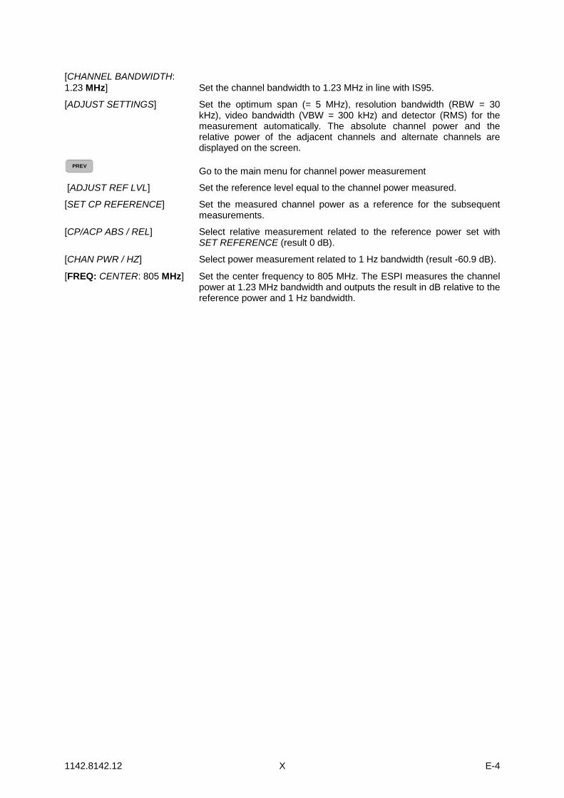
[CHANNEL BANDWIDTH:1.23 MHz] Set the channel bandwidth to 1.23 MHz in line with IS95.
[ADJUST SETTINGS] Set the optimum span (= 5 MHz), resolution bandwidth (RBW = 30kHz), video bandwidth (VBW = 300 kHz) and detector (RMS) for themeasurement automatically. The absolute channel power and therelative power of the adjacent channels and alternate channels aredisplayed on the screen.
PREVGo to the main menu for channel power measurement
[ADJUST REF LVL] Set the reference level equal to the channel power measured.
[SET CP REFERENCE] Set the measured channel power as a reference for the subsequentmeasurements.
[CP/ACP ABS / REL] Select relative measurement related to the reference power set withSET REFERENCE (result 0 dB).
[CHAN PWR / HZ] Select power measurement related to 1 Hz bandwidth (result -60.9 dB).
[FREQ: CENTER: 805 MHz] Set the center frequency to 805 MHz. The ESPI measures the channelpower at 1.23 MHz bandwidth and outputs the result in dB relative to thereference power and 1 Hz bandwidth.

1142.8142.12 Y E-4
Additional softkeys for menu FILE
For easier operation, the FILE menu was extended by softkeys ASCII FILE EXPORT and DECIMALSEP in the FILE - NEXT submenu . The softkeys are also available in the TRACE menu.
ITEMS TOSAVE/RCL
DATA SETLIST
DATA SETCLEAR ALL
EDITCOMMENT
STARTUPRECALL
SAVE
RECALL
DATA SETCLEAR
FILEMANAGER
FILE ASCII FILEEXPORT
DECIM SEP. ,
ENABLEALL ITEMS
DISABLEALL ITEMS
DEFAULTCONFIG
SELECTITEMS
EDIT
PATH
COPY
RENAME
SORT MODE
MAKEDIRECTORY
FORMATDISK
DELETE
FILE - NEXT menu:
ASCII FILEEXPORT
The ASCII FILE EXPORT softkey stores the active trace in ASCII format to adiskette.
IEC/IEEE-bus command: FORM ASC;MMEM:STOR:TRAC 1,'TRACE.DAT'
The file consists of a header, which contains important scaling parameters,and a data section, which contains the trace data.
The file header data comes in three columns separated by semicolons (;).It has the following contents:
parameter name; numerical value; default unit
The data section starts with the keyword "Trace <n>", where <n> designatesthe number of the trace to be stored. This is followed by the measured data incolumns separated by semicolons (;).
This format can be read by spreadsheet programs such as MS Excel.A semicolon (;) is to be defined as a separator between the cells of a table.
Note: Analysis programs may come in different language versions thatrequire different notations of the decimal point. By means of theDECIM SEP softkey, a decimal point (.) or a comma (,) can beselected as decimal-point notation.
For a detailed description of the ASCII file format refer to section "Selectionand Setting of Traces – TRACE Key", ASCII FILE EXPORT softkey.

1142.8142.12 Z E-4
DECIM SEP. ,
By means of the DECIM SEP softkey, one can select between a decimal point(.) and a comma (,) as decimal-point notation for the ASCII FILE EXPORTfunction.Due to the possibility of selecting between different decimal-point notations,different language versions of analysis programs (such as MS Excel) can besupported.
IEC/IEEE-bus command: FORM:DEXP:DSEP POIN
Trigger line remains on screen after leaving the TRIG menu
The line indicating the trigger level for active video trigger is preserved on the screen even if the triggermenu is abandoned.

1142.8142.12 AA E-4
New and Modified Remote Control Commands
CALCulate<1|2>:LIMit<1 ... 8>:CONTrol:SPACing LINear | LOGarithmicThis command selects linear or logarithmic interpolation for the calculation of limit lines fromfrequency points.Example: "CALC:LIM:CONT:SPAC LIN"
Characteristics: *RST value: LINSCPI: device-specific
Mode: A
CALCulate<1|2>:LIMit<1 to 8>:LOWer:SPACing LINear | LOGarithmicThis command selects linear or logarithmic interpolation for the lower limit line.Example: "CALC:LIM:LOW:SPAC LIN"
Characteristics: *RST value: LINSCPI: device-specific
Mode: A
CALCulate<1|2>:LIMit<1 to 8>:UPPer:SPACing LINear | LOGarithmicThis command selects linear or logarithmic interpolation for the upper limit line.Example: "CALC:LIM:UPP:SPAC LIN"
Characteristics: *RST value: LINSCPI: device-specific
Mode: A
CALCulate<1|2>:MARKer<1...4>:FUNCtion:POWer:SELect ACPower | CPOWer | MCACpower |OBANdwidth | OBWidth | CN | CN0
This command selects – and switches on – one of the above types of power measurement inthe selected measurement window. This function is independent of the selected marker, i.e. thenumerical suffix <1...4> appended to MARKer has no effect.The channel spacings and channel bandwidths are configured in the SENSe:POWer:ACHannelsubsystem.Please note the following:If CPOWer is selected, the number of adjacent channels (command:[SENSe:]POWer:ACHannel:ACPairs) is set to 0. If ACPower is selected, the number ofadjacent channels is set to 1, unless adjacent-channel power measurement is switched onalready.With respect to the above two settings, the behaviour of the ESPI differs from that of the ESIBfamily.
Note: The channel/adjacent-channel power measurement is performed for the trace selectedwith SENSe:POWer:TRACe 1|2|3.The occupied bandwidth measurement is performed for the trace on which marker 1 ispositioned. To select another trace for the measurement, marker 1 is to be positionedon the desired trace by means of CALC:MARK:TRAC 1|2|3.

1142.8142.12 BB E-4
Parameters: ACPower Adjacent-channel power measurement with a singlecarrier signal
CPOWer Channel power measurement with a single carriersignal (equivalent to adjacent-channel powermeasurement with NO. OF ADJ CHAN = 0)
MCACpower Channel/adjacent-channel power measurement withseveral carrier signals
OBANdwidth | OBWidth Measurement of occupied bandwidthCN Measurement of carrier-to-noise ratioCN0 Measurement of carrier-to-noise ratio referenced to
1 Hz bandwidthExample: "CALC:MARK:FUNC:POW:SEL ACP" 'Switches on adjacent-channel power
measurement in window A.Characteristics: *RST value: -
SCPI: device-specificMode: A-F
CALCulate<1|2>:MARKer<1...4>:FUNCtion:POWer:RESult? ACPower | CPOWer | MCACpower |OBANdwidth | OBWidth | CN | CN0
This command queries the result of the power measurement performed in the selected window.If necessary, the measurement is switched on prior to the query.The channel spacings and channel bandwidths are configured in the SENSe:POWer:ACHannelsubsystem.To obtain a valid result, a complete sweep with synchronization to the end of the sweep must beperformed before a query is output. Synchronization is possible only in the single-sweep mode.Parameters:ACPower: Adjacent-channel power measurement
Results are output in the following sequence, separated by commas:Power of transmission channelPower of lower adjacent channelPower of upper adjacent channelPower of lower alternate channel 1Power of upper alternate channel 1Power of lower alternate channel 2Power of upper alternate channel 2The number of measured values returned depends on the number ofadjacent/alternate channels selected withSENSe:POWer:ACHannel:ACPairs.With logarithmic scaling (RANGE LOG), the power is output in thecurrently selected level unit; with linear scaling (RANGE LIN dB or LIN %),the power is output in W. If SENSe:POWer:ACHannel:MODE REL isselected, the adjacent/alternate-channel power is output in dB.
1142.8142.12 CC E-4
CPOWer Channel power measurementWith logarithmic scaling (RANGE LOG), the channel power is output in thecurrently selected level unit; with linear scaling (RANGE LIN dB or LIN %), thechannel power is output in W.
MCACpower: Channel/adjacent-channel power measurement with several carrier signalsResults are output in the following sequence, separated by commas:1. Power of carrier signal 12. Power of carrier signal 23. Power of carrier signal 34. Power of carrier signal 45. Total power of all carrier signals6. Power of lower adjacent channel7. Power of upper adjacent channel8. Power of lower alternate channel 19. Power of upper alternate channel 110. Power of lower alternate channel 211. Power of upper alternate channel 2The number of measured values returned depends on the number ofcarrier signals and adjacent/alternate channels selected withSENSe:POWer:ACHannel:TXCHannel:COUNt andSENSe:POWer:ACHannel:ACPairs.If only one carrier signal is measured, the total value of all carrier signalswill not be output.With logarithmic scaling (RANGE LOG), the power is output in dBm;with linear scaling (RANGE LIN dB or LIN %), the power is output in W.If SENSe:POWer:ACHannel:MODE REL is selected, the adjacent/alternate-channel power is output in dB.
OBANdwidth |OBWidth
Measurement of occupied bandwidthThe occupied bandwidth in Hz is returned.
CN Measurement of carrier-to-noise ratioThe carrier-to-noise ratio in dB is returned.
CN0 Measurement of carrier-to-noise ratio referenced to 1 Hz bandwidth.The carrier-to-noise ratio in dB/Hz is returned.

1142.8142.12 DD E-4
Example of channel/adjacent-channel power measurement:"SENS2:POW:ACH:ACP 3" 'Sets the number of adjacent/alternate channels in
screen B to 3."SENS2:POW:ACH:BAND 30KHZ" 'Sets the bandwidth of the transmission channel to 30 kHz."SENS2:POW:ACH:BAND:ACH 40KHZ" 'Sets the bandwidth of each adjacent channel to
40 kHz."SENS2:POW:ACH:BAND:ALT1 50KHZ" 'Sets the bandwidth of each alternate channel to
50 kHz."SENS2:POW:ACH:BAND:ALT2 60KHZ" 'Sets the bandwidth of alternate channel 2 to 60 kHz."SENS2:POW:ACH:SPAC 30KHZ" 'Sets the spacing between the transmission channel
and the adjacent channel to 30 kHz, the spacingbetween the transmission channel and alternatechannel 1 to 60 kHz, and the spacing between thetransmission channel and alternate channel 2 to 90 kHz.
"SENS2:POW:ACH:SPAC:ALT1100KHZ"
'Sets the spacing between the transmission channeland alternate channel 1 to 100 kHz, and the spacingbetween the transmission channel and alternatechannel 2 to 150 kHz.
"SENS2:POW:ACH:SPAC:ALT2140KHZ"
'Sets the spacing between the transmission channeland alternate channel 2 to 140 kHz.
"SENS2:POW:ACH:MODE ABS" 'Switches on absolute power measurement."CALC2:MARK:FUNC:POW:SEL ACP" 'Switches on the adjacent-channel power measurement
in screen B."INIT:CONT OFF" 'Switches over to single-sweep mode."INIT;*WAI" 'Starts a sweep and waits for the end of the sweep."CALC2:MARK:FUNC:POW:RES? ACP" 'Queries the result of adjacent-channel power
measurement in screen B."SENS2:POW:ACH:REF:AUTO ONCE" 'Defines the measured channel power as the
reference value for relative power measurements.
If the channel power only is to be measured, all commands relating to adjacent/alternatechannel bandwidth and channel spacings are omitted. The number of adjacent/alternatechannels is set to 0 with SENS2:POW:ACH:ACP 0.Example of occupied bandwidth measurement:
"SENS2:POW:BAND 90PCT" 'Defines 90% as the percentage of the powerto be contained in the bandwidth range to bemeasured.
"INIT:CONT OFF" 'Switches over to single-sweep mode."INIT;*WAI" 'Starts a sweep and waits for the end of the
sweep."CALC2:MARK:FUNC:POW:RES? OBW" 'Queries the occupied bandwidth measured
in screen B.Characteristics: *RST value: -
SCPI: device-specificMode: A-FThis command is a query and therefore has no *RST value.

1142.8142.12 EE E-4
DISPlay[:WINDow<1|2>]:SIZE LARGe | SMALlThis command switches the measurement window for channel and adjacent-channel powermeasurements to full screen or half screen. Only "1" is allowed as a numerical suffix.Example: "DISP:WIND1:SIZE LARG" 'Switches the measurement window to
full screen.Characteristics: *RST value: SMALl
SCPI: device-specificMode: A, 3G FDD
DISPlay[:WINDow<1|2>]:TRACe<1...3>:Y:SPACing LINear | LOGarithmic | LDBThis command defines linear or logarithmic scaling for the selected measurement window. Forlinear scaling, the unit % (command DISP:WIND:TRAC:Y:SPAC LIN) or dB (commandDISP:WIND:TRAC:Y:SPAC LDB) can be selected.The numerical suffix <1...3> appended to TRACe has no effect.
Example: "DISP:WIND1:TRAC:Y:SPAC LIN"
Characteristics: *RST value: LOGarithmicSCPI: conforming
Mode: A
:[SENSe<1|2>:]CORRection:YIG:TEMPerature:AUTO ON | OFFThis command switches on or off the automatic correction of the YIG filter frequency drift.When correction is switched on, it is checked once per minute whether the temperature on theYIG filter has changed by more than 5K relative to the last instance of correction. If this is thecase, the frequency of the YIG filter is – at the end of the next measurement – adjusted asrequired for the new temperature. For time-critical applications, the correction function can beswitched off after an operating period of ≥ 30 minutes.Example: "CORR:YIG:TEMP OFF" 'Switches off automatic correction of the
YIG filter frequency drift.Characteristics: *RST value: ON
SCPI: device-specificMode: allThis command is available only from firmware version 1.72.The ON parameter is available only if the MW CONV UNIT module has one of the followingmodification states:Order No. Rev SubRev1130.2396 ≥ 02 ≥ 011130.2544 ≥ 02 ≥ 01
SENSe:LIST SubsystemThe commands of this subsystem are used for measuring the power at a list of frequency pointswith different device settings. The measurement is always performed in the time domain (span =0 Hz).The number of frequencies is now extended to 200 entries.

1142.8142.12 FF E-4
[SENSe<1|2>:]POWer:ACHannel:SPACing:CHANnel 100 Hz to 2000 MHzThis command defines the channel spacing for the carrier signals.The command is available only for measurements in the frequency domain (span > 0).Example: "POW:ACH:SPAC:CHAN 25kHz"
Characteristics: *RST value: 20 kHzSCPI: device-specific
Mode: A-F
[SENSe<1|2>:]POWer:ACHannel:TXCHannel:COUNt 1 | 2 | 3 | 4This command selects the number of carrier signals.The command is available only for multicarrier channel and adjacent-channel powermeasurements (CALC:MARK:FUNC:POW:SEL MCAC) in the frequency domain (span > 0).Example: "POW:ACH:TXCH:COUN 3"
Characteristics: *RST value: 4SCPI: device-specific
Mode: A-F
[SENSe<1|2>:]POWer:ACHannel:REFerence:TXCHannel:AUTO MINimum | MAXimum | LHIGhestThis command activates the automatic selection of a transmission channel to be used as areference channel in relative adjacent-channel power measurements.The transmission channel with the highest power, the transmission channel with the lowestpower, or the transmission channel nearest to the adjacent channels can be defined as areference channel.The command is available only for multicarrier channel and adjacent-channel powermeasurements (CALC:MARK:FUNC:POW:SEL MCAC) in the frequency domain (span > 0).Parameters: MINimum Transmission channel with the lowest power
MAXimum Transmission channel with the highest powerLHIGhest Lowermost transmission channel for the lower adjacent channels,
uppermost transmission channel for the upper adjacent channelsExample: "POW:ACH:REF:TXCH:AUTO MAX" 'The transmission channel with the
highest power is used as areference channel.
Characteristics: *RST value: -SCPI: device-specific
Mode: A-F
[SENSe<1|2>:]POWer:ACHannel:REFerence:TXCHannel:MANual 1 | 2 | 3 | 4This command selects a transmission channel to be used as a reference channel in relativeadjacent-channel power measurements.The command is available only for multicarrier channel and adjacent-channel powermeasurements (CALC:MARK:FUNC:POW:SEL MCAC) in the frequency domain (span > 0).Example: "POW:ACH:REF:TXCH:MAN 3" 'Transmission channel 3 is used as a
referencechannel.Characteristics: *RST value: 1
SCPI: device-specificMode: A-F
1142.8142.12 GG E-4
[SENSe<1|2>:]POWer:ACHannel:PRESet ACPower | CPOWer | MCACpower | OBANdwidth |OBWidth | CN | CN0
This command adjusts the frequency span, the measurement bandwidths and the detector asrequired for the number of channels, the channel bandwidths and the channel spacings selectedin the active power measurement. If necessary, adjacent-channel power measurement isswitched on prior to the adjustment.To obtain valid results, a complete sweep with synchronization to the end of the sweep must beperformed after the adjustment. Synchronization is possible only in the single-sweep mode.The result is queried with the command CALCulate:MARKer:FUNCtion:POWer:RESult?.The command is available only for measurements in the frequency domain (span > 0).Example: "POW:ACH:PRES ACP" 'Sets the frequency span, the
measurement bandwidths and the detector asrequired for the ACP measurement in screen A.
"INIT:CONT OFF" 'Switches over to single-sweep mode."INIT;*WAI" 'Starts a sweep and waits for the end of
the sweep."CALC:MARK:FUNC:POW:RES? ACP" 'Queries the result of the adjacent-channel
power measurement.Characteristics: *RST value: -
SCPI: device-specificMode: A-F
[:SENSe<1|2>:]SWEep:POINts <numeric_value>This command defines the number of measurement points for one sweep run.Parameter: <numeric_value>::= 125, 251, 501, 1001, 2001, 4001, 8001Example: "SWE:POIN 251"
Characteristics: *RST value: 501SCPI: conforming
Modes: A
:TRACe:FEED:CONTrol<1 to 4> ALWays | NEVer
This command switches block data transmission during a scan on and off.
Example: "TRAC:FEED:CONT ALW"
Features: *RST Value: NEVerSCPI: conforming
Mode: R
The block size depends on the scan time, the trace number is not evaluated.