superposed buckling in multilayers
TRANSCRIPT

Journal of Structural Geology, Vol. 15, No. 1, pp. 95 to 111, 1993 0191-8141/93 $06.00+0.(X1 Printed in Great Britain © 1993 Pergamon Press Ltd
Superposed buckling in multilayers
S. K. GHOSH, N. MANDAL, S. SENGUPTA, S. K. DEB and D. KHAN
Department of Geological Sciences, Jadavpur University, Calcutta 700 032, India
(Received 5 November 1991; accepted in revised )'orm 30 June 1992)
Abstract--Experiments with soft models indicate that, just as in the case of a single-layer, the mode of superposed buckling in multilayers is essentially controlled by the shape of the early folds. A thin multilayer embedded in an incompetent host may undergo superposed buckling in any one of the four standard modes observed in single-layers. In general, however, the geometry of superposed folds is more varied in multilayers. A fifth mode appears only in multilayers, whereas the other four standard modes may be modified during refolding in multilayers. When different orders of buckling folds develop, the interference pattern of the smaller folds is distorted by that of larger disharmonic folds. There are several consequences of this distortion: (i) the degree of complexity of outcrop may vary in layers of different lithology; (ii) a morphology similar to that produced by three or more generations of superposed folds may develop even when there arc only two distinct events of deformation; and (iii) there may be a significant lowering of the axial direction stability of the new folds. The experiments also indicate that the type 1 interference pattern may be produced in mode 1, mode 2, modified mode 2 and mode 5 folding. In addition, the experiments show that there are somc special features associated with superposed buckling of parallel flexural-slip folds in thick multilayers.
INTRODUCTION
THE mode of superposed buckling is controlled essen- tially by the shapes of the early folds. Depending upon the initial tightness of the early folds we can distinguish the following four modes of superposed buckling in single-layers (Ghosh et al. 1992) (Fig. 1). In mode 1 a dome-and-basin structure arises when the early fold (F1) is very gentle. In mode 2, when early folds have rounded hinge zones and interlimb angles roughly between 135 ° and 90 ° the second generation folds (F2) ride over the
' - .3. ~.... { T 3 . .+4 . i ! .V i " " 4.
t F~'~
¢ d Fig. 1. Four standard modes of superposed buckling in single-layers. (a) First mode with dome-and-basin pattern. (b) Second mode with small F 2 folds riding over larger Fl fold. (c) Third mode with develop- ment of non-plane non-cylindrical folds and with hinge replacement. Dashed line--material line which was initially parallel to F I hinge. (d) Fourth mode with development of non-plane non-cylindrical folds
without hinge replacement.
hinges of F l, the F 2 folds being distinctly smaller than F l . In mode 3, when the interlimb angle of F 1 is less than 90 ° but the fold is not very tight or isoclinal, the fold geometry becomes non-plane non-cylindrical; however, the non-plane fold is generated by the development of a new sinuous hinge line (FI) which replaces the old hinge line of F1. In plan view the F2 folds are triangular and their axial planes are approximately normal to the direc- tion of second compression (P2). In mode 4, when Fl is very tight or isoclinal and has narrow hinge zones, the non-plane non-cylindrical folds develop without accom- panying hinge replacement.
The morphology of superposed buckling folds in multilayers is much more varied; this is mainly because the profile shapes of F 1 folds are more varied in multi- layers than in isotropic single-layers. Moreover, if thin and thick layers of varying competence are intercalated in such a manner that the multilayer can give rise to more than one order of buckling folds, the comparatively small superposed folds in a thin layer are also affected by the larger folds in the thicker layers. This often leads to the development of more complex forms of superposed folds than that obtained in superposed buckling in a single layer. The present study, based on experiments with multilayered test-models, mainly aims to dis- tinguish the diverse forms of superposed folds produced by the interference of different orders of buckling folds in two separate deformations. In addition, we also examine the problem of the refolding of parallel folds in thick multilayers in which the adjoining antiforms and synforms are usually of quite different shapes and there is a strong variation in the curvature of the layers at hinge zones at different levels.
We shall be concerned here with the problem of development of non-cylindrical folds by refolding of a set of cylindrical folds. The problem of coaxial folding is outside the scope of the present investigation.
95

96 S .K . GHOSrL N. MANDAL, S. SENGUPTA, S. K. DEB and D. KHAN
DEVELOPMENT OF DIFFERENT ORDERS OF FOLDS
The arc-length of folds in an embedded competent layer is controlled by layer thickness and competence contrast or viscosity contrast with the embedding me- dium. The viscosity ratio also controls the ratio of the rates of buckle-shortening and layer-parallel strain (Ramberg 1964). If the viscosity ratio is large the fold grows in amplitude at a rapid rate. At a small or moderate viscosity ratio there is a rapid increase in layer thickness and a slow growth of fold amplitude. If the multilayer contains thin and thick competent layers and the spacing between them is slightly larger than half the initial wavelength of the small folds in thin layers, the small folds in a thin competent layer acquire a significant amount of buckle-shortening when the folds in a thicker and somewhat less competent layer still have a very small or negligible amplitude/wavelength ratio. With progressive shortening of the muitilayer, when the am- plitude of the larger folds has also become sufficiently large, the thin layer as a whole is deformed by contact strain into larger waves (Fig. 2) and gives rise to anticli- noria and synclinoria (Ramberg 1964). In rocks which
Cl
b
¢ Fig. 2. (a) Initial multilayer embedded in an incompetent material. The thin black layer at the middle is a competent layer of viscosity ~t. The thick dotted layers with viscosity/~2 also behave as competent units. Blank~incompetent material with viscosity/~3./~l >/~2 >/~3. (b) Early stage of layer-parallel shortening with small buckle folds in /~ 1 layer, while/~2 layers have mostly shortened by layer-parallel strain. (c) Later stage of shortening with/~2 layers forming larger folds. The ~l
layer is now deformed by two orders of folds.
contain layers of different thicknesses and different competences several orders of buckling folds can form in this manner.
EXPERIMENTAL METHOD
Two types of multilayers were used in these experi- ments: (1) the majority (51) of experiments were carried out with multilayers which produce two orders of buckle-folds. Each multilayer in these experiments con- sisted of a 2 mm thick competent layer of modelling clay sandwiched between two 5 - 6 m m thick incompetent layers of painter's putty and with a 4 mm thick com- petent layer of soft modelling clay (modelling clay mixed with putty) on either side. The proportion of putty mixed with the modelling clay was varied to obtain different competence contrasts between the thin and thick competent layers. The entire multilayer was sand- wiched between two thick slabs of painter's putty (Fig. 2a). Under a layer-parallel shortening the multilayers gave rise to two orders of buckling folds (Figs. 2b & c); (2) in four of the experiments a thick slab of multilayer was built up by assembling 2 mm thick layers of model- ling clay with the interfaces smeared with oil or a mixture of oil and grease so that the adjoining layers could easily slide past each other. Modelling clay of two different colours was used for alternate layers. The entire multi- layer with a total thickness of about 20-50 mm was sandwiched between two thick slabs of painter's putty. Under layer-parallel shortening the multilayers were deformed to parallel folds in which the curvature at the hinge changed from layer to layer.
While assembling the first type of multilayers (those which gave rise to two orders of folds) the top surface of the thin stiff layer and the top surface of one of the thick competent layers in many of the models were lightly dusted with talc powder. After the final deformation the overburden above each or these layers could be removed in turn and the three-dimensional forms of the interfering folds could be exposed on these surfaces. The veneer of talc at the interface was mostly absorbed by the adjoining layer of putty. The layers on either side of an interface were folded harmonically and there was no d6collement along the interface. By comparing with models in which a talc veneer was not used, it was found that the presence of this veneer did not affect the mode of superposed buckling.
The models were deformed in a pure-shear apparatus with the direction of maximum shortening and the direction of no strain horizontal. Models were free to extend in a vertical direction. The layering in the models was initially oriented in a horizontal position. The method of deformation of the model was the same as described in Ghosh et al. (1992). During the second deformation the direction of maximum shortening was parallel to the F 1 axis in all but seven of the experiments. In seven experiments (all with multilayers showing two orders of folds), the direction of second shortening (P2)

Superposed buckling in multilayers 97
was at an angle of about 15-20 ° to the F 1 axis. In four of these P2 was parallel to the enveloping surface of Fl. In the other three a thin wedge was cut from the base of the model after the first deformation so that when the model was placed in the pure-shear box, P2 was horizontal whereas the Ft axis plunged at an angle of 15-20 ° towards the direction of P2.
In the first type of multilayer, the first and the second generation folds in the thick competent units are de- scribed here as FIL and F2t .. The thin competent layers are deformed to two orders of folds. The larger folds of the two generations in the thin layer are evidently FZL and F2L. The smaller folds affecting the same layer will be described as Fzs and F2s. In other words the thin layer may show Fls, Fzs, FIL and F2L. In the following descrip- tion, whenever we refer to a model with two orders of folds it should be understood that the experiment was carried out with the first type of multilayer.
SUPERPOSED BUCKLING OF TWO ORDERS OF FOLDS
General
When we consider only the smaller folds (Fls and F2s) of the two generations in the first type of multilayer, their interference, depending on the tightness of Fls, gives rise to any one of the four modes of superposed buckling (Ghosh et al. 1992). In a similar way, any one of the four modes of superposed buckling may occur by interference of F1L and F2L. However, when two orders of folds developed in the experiments, the larger folds (FiE or F2L) on the thicker layers were usually somewhat less tight than the smaller folds (Fls or F2s) in the thinner layer. Consequently, the mode of superposed buckling resulting from Fls-F2s interference could be the same as or different from the buckling mode of FiL-F2L inter- ference. From the experiments we find that we may have the following combinations:
(1) Fls-F2s interference in the first mode distorted by larger F1L--F2L interference in the first mode;
(2) Fts-FEs in second mode, with FIL--F2L in the first mode;
(3) Fzs-F2s in second mode, with FtL-F2L also in second mode;
(4) Fls-F2s in third mode, with FIL-F2L in first mode; (5) F~s-F2s in third mode, with FIL-F2L in second
mode; (6) F~s-F2s in third or fourth mode, with FIL--F2L also
in third or fourth mode.
We describe the characteristic features of each case separately in the following sections. Because of a spatial variation in tightness of the F1 folds, there was often a close spatial association of two or more of these combi- nations in the individual models. These spatial vari- ations of the modes of superposed buckling are described in a later section.
b,
tl
b Fig. 3. (a) Case l: the relatively small domes and basins of F~s-F2 s interference are distorted over a larger dome of F lrF2L interference. (b) With progressive shortening during second deformation, the hinge line curvature of the dome-and-basin structure is greatly accentuated.
Case 1: Fts-F2s in first mode, FIL-FzL in first mode
When both F~s and FSL are gentle (Fleuty 1964) the second deformation produces two orders of domes and basins (Figs. 3 and lla). The larger scale structure always shows a type 1 interference (Ramsay 1967, p. 521) as in the first mode of superposed buckling in a single-layer (Ghosh et al. 1992). However, unless the larger F2 folds are isoclinal, the smaller domes and basins in the thin layer sometimes have gently curved trends when they occur at the flanks of the larger folds. As a result, the smaller structure may give rise to a type 2 interference. With further shortening and with a large stretching normal to the enveloping surface, the ampli- tudes of both the smaller and the larger domes and basins increase. With a very large shortening in the second deformation, the domes and basins are greatly elongated normal to the enveloping surfaces and give rise to two orders of sheath folds.
Case 2: Fls-F2s in second mode, F1L-F2L in first mode
There was a distortion of the Fls-F2s interference in the second mode by the larger domes and basins when the FIL folds in the thick layers were gentle but the smaller Fls folds in the thin layer were moderately open. During the second deformation the F2s folds in the thin layer rode over the hinges of the F~s folds according to the second mode of superposed buckling; the F2s folds were distinctly smaller than the Fls. The superposition
98 S. K. GHOSH, N. MANDAL, S. SENGUPTA, S. K. DEB and D. KHAN
A
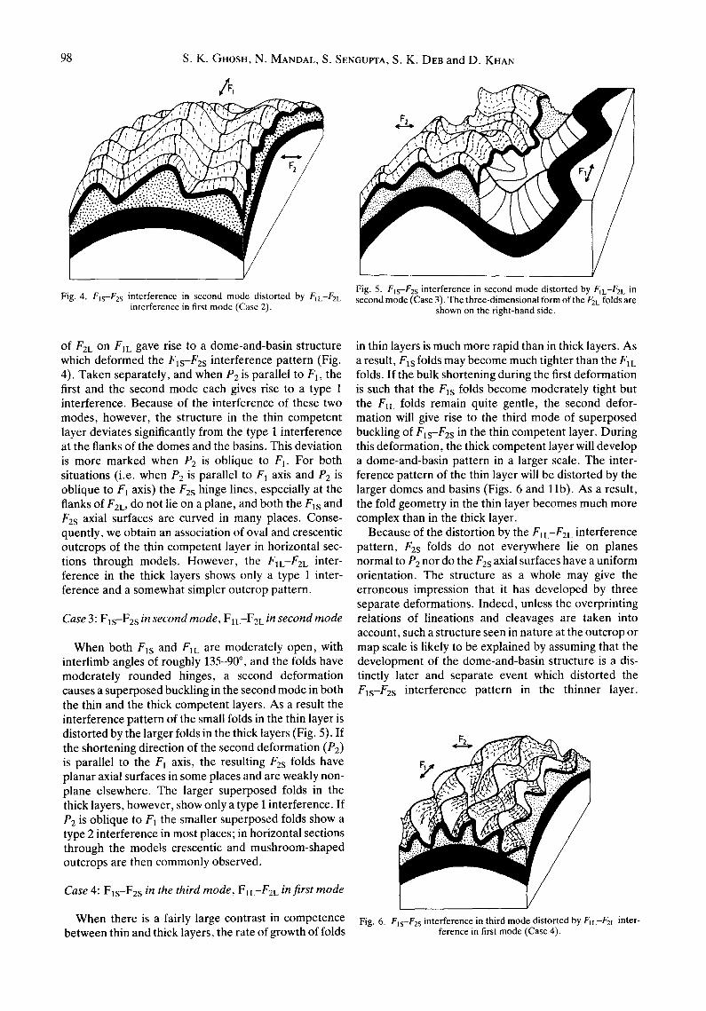
Fig. 4. Fls-F2s interference in second mode distorted by FIL-F2L interference in first mode (Case 2).
Fig. 5. Fls-F2s interference in second mode distorted by FIL-F2L in second mode (Case 3). The three-dimensional form of the F2L folds are
shown on the right-hand side.
of F2L on FIL gave rise to a dome-and-basin structure which deformed the Fls-Fzs interference pattern (Fig. 4). Taken separately, and when P2 is parallel to F1, the first and the second mode each gives rise to a type 1 interference. Because of the interference of these two modes, however, the structure in the thin competent layer deviates significantly from the type 1 interference at the flanks of the domes and the basins. This deviation is more marked when P2 is oblique to F I. For both situations (i.e. when P2 is parallel to F 1 axis and P2 is oblique to Ft axis) the F2s hinge lines, especially at the flanks of F2L, do not lie on a plane, and both the Fas and F2s axial surfaces are curved in many places. Conse- quently, we obtain an association of oval and crescentic outcrops of the thin competent layer in horizontal sec- tions through models. However, the FlL--F2L inter- ference in the thick layers shows only a type 1 inter- ference and a somewhat simpler outcrop pattern.
Case 3: Fls-F2s in second mode, FIL--F2L in second mode
When both Fls and F1L are moderately open, with interlimb angles of roughly 135-90 °, and the folds have moderately rounded hinges, a second deformation causes a superposed buckling in the second mode in both the thin and the thick competent layers. As a result the interference pattern of the small folds in the thin layer is distorted by the larger folds in the thick layers (Fig. 5). If the shortening direction of the second deformation (P2) is parallel to the F 1 axis, the resulting F2s folds have planar axial surfaces in some places and are weakly non- plane elsewhere. The larger superposed folds in the thick layers, however, show only a type i interference. If P2 is oblique to F1 the smaller superposed folds show a type 2 interference in most places; in horizontal sections through the models crescentic and mushroom-shaped outcrops are then commonly observed.
Case 4: Fls-Fes in the third mode, F1L--F2L in first mode
When there is a fairly large contrast in competence between thin and thick layers, the rate of growth of folds
in thin layers is much more rapid than in thick layers. As a result, Fls folds may become much tighter than the ElL folds. If the bulk shortening during the first deformation is such that the Fts folds become moderately tight but the ElL folds remain quite gentle, the second defor- mation will give rise to the third mode of superposed buckling of F~s-F2s in the thin competent layer. During this deformation, the thick competent layer will develop a dome-and-basin pattern in a larger scale. The inter- ference pattern of the thin layer will be distorted by the larger domes and basins (Figs. 6 and 11b). As a result, the fold geometry in the thin layer becomes much more complex than in the thick layer.
Because of the distortion by the FIL-F2L interference pattern, F2s folds do not everywhere lie on planes normal to P2 nor do the F2s axial surfaces have a uniform orientation. The structure as a whole may give the erroneous impression that it has developed by three separate deformations. Indeed, unless the overprinting relations of lineations and cleavages are taken into account, such a structure seen in nature at the outcrop or map scale is likely to be explained by assuming that the development of the dome-and-basin structure is a dis- tinctly later and separate event which distorted the Fls-F2s interference pattern in the thinner layer.
Fig. 6. Fls-F2s interference in third mode distorted by FIL-F2L inter- ference in first mode (Case 4).

Superposed buckling in multilayers 99
Although in the experiments also the dome-and-basin structure in the thick layers gained prominence after the Fls-F2s interference was already well-developed, the assumption of three separate deformations will be erroneous for the following reasons:
(a) in the experiments the layer-parallel strain and the concomitant thickening of the thick layers were taking place from the very beginning of the second deformation. In rocks, because of the large layer- parallel homogeneous strain a cleavage may also initiate perpendicular to P2 at this early stage;
(b) the rate of growth of the amplitude/wavelength ratio of F2L during the initial stage of the second defor- mation is very small but not zero, and there is a gradual increase in its rate of growth during the progressive deformation (Ramberg 1964). In other words, F2s and F2L are broadly synchronous although the growth rate of F2s is much more rapid than that of F2L.
Case 5: Fls-F2s in the third or fourth mode, FIL-F2L in second mode
Depending upon the contrast in the rates of buckle- shortening in thin and thick competent layers, Fls folds may become moderately tight (with interlimb angles less than 90 °) while Flc folds are somewhat less tight during the second deformation; then, Fls folds are refolded in the third mode while the fold interference in the thick layer is in the second mode (Fig. 7). As mentioned earlier, the third mode of superposed buckling is associ- ated with the phenomenon of hinge replacement (Ghosh et al. 1992). Consequently, Fls hinges are obliterated and sinuous new hinge lines (F'ls) are created during the second deformation. Ordinarily, the F 2 folds associated with the third mode of fold-superposition have hinge lines and axial surfaces approximately perpendicular to P2. In the present case (Fig. 7), however, because of the interfering effect of FIL-F2L superposition, the F2s fold hinges do not lie on a plane perpendicular to P2 nor do the F2s axial surfaces remain everywhere planar. In horizontal sections through the models, the 'outcrops' of the thin competent layer show a fanning and occasional curving of the axial surface traces of F2s. A similar situation also arises when the Fls-F2s is in the fourth mode.
Figure 7 shows that there is a strong disharmony between the hinge lines of F2s and F2L; F2s hinge lines are more sinuous and may have much steeper plunges than F2L hinge lines. If such structures occur in natural rocks, the sharp contrast in the attitudes of the relatively large and small structures may be misinterpreted by assuming that there are three distinct phases of defor- mation instead of two. Where there is an early lineation parallel to the F~L hinges in the thick layers, and ifF2L is a flexural fold the lineation can be unrolled by rotation around the local F2L hinge line. In the thin layer on the other hand, because of hinge replacement in the third mode of superposed buckling, the Fls hinge lines are obliterated and the lineation will be oblique to the newly created F~s hinge lines. The early lineation in the thin
Fig. 7. Fjs-F2s interference in third mode distorted by FIL--/'2L inter- ference in second mode (Case 5). The three-dimensional form of the F~L-FzL interference in the thick competent layer is shown on the right-hand domain. Note that the plunge of F2s hinge is much steeper
than that of F2L in most domains.
layer may not then be unrollable by rotation around either the F2s or the F2L hinge lines.
Case 6: Fls-F2s in the third mode or fourth mode, FIL-F2L in the third or fourth mode
When a single order of cylindrical folds is refolded in the third mode, the axial surfaces of the F 2 folds are more or less planar. In the case shown in Fig. 8, the large F2L folds in the thick layers do have more or less planar axial surfaces. However, the refold structure in the thin layer becomes more complex for the following reasons.
(1) The F2c hinge lines have a somewhat different orientation than the F2s hinge lines. Because of a ro- tation around the F2L hinge lines there is fanning of the F2s axial surfaces. The F2s hinge lines are also distorted by this rotation.
(2) A further distortion of the F2s axial surfaces and of their hinges is caused by the hinge replacement of F1L
Fig. 8. Fis-F2s interference in fourth mode distorted by FIL-F2L interference in the third mode (Case 6). The hinge lines and axial surfaces of F2s folds are distorted partly by hinge replacement of FIL and partly by rotation around the F2L axis. F2s and F2L hinge lines are disharmonic and the axial direction stability of F2s is much lower than
that of F2L. Pumpelly's rule does not hold for either F l or F2 folds.

100 S.K. GHOSH, N. MANDAL, S. SENGUPTA, S. K. DEB and D. KHAN
folds and the gradual migration of the newly created F1L hinges. As indicated by Ghosh et al. (1992), the process of hinge replacement is associated in some places with a change in curvature or even a reversal in the sense of curvature of the layer. The hinge replacement in the larger folds, therefore, causes a distortion of the refold pattern in the thin layer. For this reason, the geometry of the small folds may become extremely complex in some places and may involve a rotation and bending of the hinges and axial surfaces of both Fls and F2s (Fig. 11c).
On the whole, when the FIL-F2L interference is in the third mode and Fxs-F2s interference in either the third or the fourth mode, the Fls (or Fis) hinge lines neither lie parallel to a plane nor do they maintain a constant angular relation with the F2L hinges over a small cylin- drical segment of the latter. The orientation pattern of the F2s axes is also significantly different from that of the F2L axes in the thick layers. In areas of superposed folding it is often assumed that small and large folds of the same generation are broadly coaxial. This is gener- ally known as Pumpelly's rule (Pumpelly et al. 1894). In the present instance, although the F2s and F2L folds belong to the same generation, they may have divergent attitudes. If similar structures occurred in natural rocks and unless the interrelations of associated cleavages and lineations are taken into account, it is likely that they would be misinterpreted under the assumption that the structures had formed by more than two phases of deformation.
When the shortening in the first deformation is large enough for the development of isoclinal or very tight F 1 s and F1L, their refolding takes place in the fourth mode. The hinges and axial surfaces of both the small and the large F~ folds are deformed to produce non-plane non- cylindrical folds without accompanying hinge replace- ment. Excepting a slight fanning of the F2s axial sur- faces, the geometry of the small superposed folds in the thin layer is more or less the same as the larger structure in the thick layer.
SPECIAL MODES OF SUPERPOSED BUCKLING IN MULTILAYERS
Non-development of Fes folds: fifth mode of superposed buckling
The F2s folds did not develop or were very weakly developed in certain domains or in the major part of some of the models. During the second deformation the hinge lines of the small Fls folds were then deformed by the larger F2L folds. This pattern of small Fls folds riding over larger later folds across their hinges (Fig. 9) was not seen during superposed buckling of single-layers. The mode of refolding does not belong to any one of the four modes of buckling described earlier (Ghosh et al. 1992). In the following discussion this will be described as the fifth mode. The fifth mode is morphologically similar to the second mode. However, in the second mode, rela- tively small second generation folds ride over the hinges
/
Fig. 9. Fifth mode of superposed buckling. The F2s folds are absent while Fls, FiE and RE are well-developed. The hinge lines of small Fis
folds are deformed to larger waves of F2L.
of larger first generation folds whereas, in the fifth mode, the hinges of relatively smaller first generation folds are bent over larger second generation folds.
It is not clear why F2s folds were absent in certain domains even when Fls was well developed. Such spora- dic development of a particular generation of folds is also occasionally seen in nature. It is likely that, during the first deformation, the FIE hinge line became slightly undulating because of small differences in the growth rate in different places. These undulations might have accentuated the growth rate of F2L during the second deformation and thereby inhibited the disharmonic growth of F2s.
Non-development of F is folds: modified second and third modes
In some models FIS folds were absent or were very weakly developed although F~L, F2s and F2L were well developed. If F1L was gentle to moderately open and had rounded hinges, the small F2s folds in the thin layer rode over the larger FiE folds across their hinges (Fig. 10b). This mode of superposition is similar to the second mode. There is, however, a difference from the standard second mode in single-layers (Fig. 10a) where the arc- length of the larger early folds is never greater than three of four times the arc-length of the smaller later folds. On the other hand, in the present case, when Fls folds are absent, the arc-length of a FIL fold may be very much larger than the F2s folds which ride over them. To distinguish it from the standard type of second mode, wherever such a distinction is possible, this mode of superposed buckling will be described as a modified second mode. In standard superposed buckling in the second mode, the arc-lengths of F2s are smaller than the dominant arc-length obtained by cylindrical buckle- folding of a planar, embedded single-layer. For the modified second mode the arc-lengths of the smaller F2 folds are roughly equal to the dominant arc-length. Another modification of the second mode was observed when FIE was somewhat tighter (open to close folds of
Superposed buckling in multilayers 101
i ( i j ~ 2
,,r,
' / f / ,
/ / %
c
Fig. 10. Distinction between the standard second mode (a) and the modified second (b) & (c) and third modes (d).
Fleuty 1964) and had a subrounded hinge. Under this situation, the small second generation folds developed on the limbs of the larger fold but did not cross over its hinge (Fig. 10c). With progressive hinge-parallel short- ening during the second deformation the morphology of this modified second mode changes over to another type of fold superposition in which the F~L hinge line is folded with lateral deflections and gives rise to non-plane non- cylindrical folds. The refolding is accompanied by hinge replacement as in the third mode. Yet unlike the stan- dard third mode in a single layer, where the first and the second generation folds have roughly the same size, the second generation folds are much smaller than the first generation folds (Fig. 10d). This mode of superposed buckling will be referred to as the modified third mode. In some of the models where FIL-FzL interference has produced axial culminations and depressions of antifor- mal FiE hinge line, the Fzs folds deform the FIE hinge line in modified mode 3 only in the zones of axial depressions, whereas the F2s folds occur only at the limbs of FiE in accordance with modified mode 2 in domains of axial culmination (Fig. 17d). The zones of axial depression of the antiformal folds had evidently undergone a larger hinge-parallel shortening than the zones of axial culmination. For synformal FiE, the modified third mode is seen in zones of axial culmi- nation. If close F~L folds have initially sharp hinges, the modified third mode develops even at a moderate hinge- parallel shortening.
The development of disharmonic folds in a multilayer depends, among other things, on relative thickness of the incompetent layers. If the incompetent layers separ- ating the competent layers are too thin, the multilayer deforms harmonicly (Ramberg 1964). This might have been the reason for the non-development of Fts folds in some of the models. During the first deformation
the initial thickness of the incompetent layer (i.e. the spacing between competent layers) might have increased by layer-parallel compression, and this might have facilitated the development of the disharmonic F2s and F2L folds in the later deformation.
SPATIAL VARIATION OF DIFFERENT MODES
The development of folds during both deformations was not always uniform throughout a model. In many of the models the tightness of F~ (F~s or F t L or both) varied from place to place. When there was a large contrast in tightness the mode of superposed buckling was also different in different parts of the model. As a result the geometry of superposed folds became quite complex. A few examples of such complex patterns are described below.
A clear example of distortion of small-scale super- posed folds by larger folds is shown by model 91/106 (Fig. 12). Because of a considerable competence con- trast between the thick and thin layers of modelling clay, Fls folds are in many places tight or isoclinal whereas FIL folds are always gentle. Figure 12(a) shows the three-dimensional form of the FIL--F2L inter- ference on a thick layer after its overburden is removed. The F1L-F2L interference is in the first mode. The shortening in the second deformation was larger than in the first deformation. As a result, the F2L folds are tighter than the F~L. The hinges of the moderately tight F2L folds rise and fall in axial culmi- nations and depressions over gentle F1L folds. This simple form is in sharp contrast with the much more complex geometry of the smaller folds in the thin com- petent layer. Figure 12(b) shows the superposed folds in the exposed thin layer of the same model after removal of the overburden. The Fls folds on this sur- face show a large variation in tightness from place to place and are not well developed everywhere. Where F~s folds are very tight or isoclinal, their axial surfaces have been folded in the fourth mode. This interference pattern has been further distorted by the larger anti- forms and synforms of F2L (Figs. 12b & c). The axial surfaces of the F2s folds in these domains are diversely oriented over the larger F2L folds. Thus the F2s folds are upright at the hinge zones of F2L, whereas they are inclined or reclined at the flanks of F2L folds. This is not the only mode of superposed buckling in this model. Where Fls folds are absent or are very weak, the hinge lines of the F2s folds are bent to large arcs over the gentle FiL folds (Figs. 12b & c) in modified mode 2. In segments where both Fls and ~ s are gen- tle, their interference has produced gentle domes and basins in the first mode. These smaller domes and basins are further deformed by a larger elongate dome resulting from F1L-F2L interference.
The Fls folds did not develop in most parts of the model 91/86 (Figs. 13a and 15). On the left-hand side of Fig. 15 in the segment marked B, the thin com- petent layer is deformed to a sharp-hinged antiformal
5G 15: I-G

102 S.K. GHOSH, N. MANDAL, S. SENGUPTA, S. K. DEB and D. KHAN
FIe with an interlimb angle of about 90 °. The hinge and axial surface of this fold are deformed into a zig- zag pattern by the modified third mode. The hinges of the relatively small F2s folds are also somewhat sharp but where these folds enter into the open synformal region of segment C the folds become more rounded and ride over the trough of a larger scale basin in accordance with modified mode 2. In the domain marked D in the central part of the model, there is a dome-and-basin structure of interfering Fls and F2s deformed as a whole into a larger basin. In the front left- and right-hand sides of the model (Fig. 15), in segments A, small F2s folds have developed only in the limb region of a larger F~c antiform in accordance with the modified second mode.
The thick competent layer in model 91/90 (Figs. 13b and 16) has been deformed in the first mode, with development of relatively large domes and basins. In the central part of the model (segment B of Fig. 16a), the thin layer with Fls-F2s interference has been de- formed in the fourth mode; this pattern has been dis- torted as a whole into a large basin (Fig. 16b). The F2s folds are absent in the left and right parts of the model labelled A on Fig. 16, the front and rear segments in Fig. 13b. The Fls folds in these segments ride over the larger F2c folds in the fifth mode. In the vicinity of C on Fig. 16(a) (right centre portion of Fig. 13b), small F~s and F2s are distorted by a larger-scale basinal structure.
The superposed buckling in model 91/97 (Fig. 13c) took place as in the sixth case described earlier. In the centre of the model F~s-F2s interference in the fourth mode is distorted by a F1L-F2c interference in the third mode. The F2s and F2L hinge lines are not parallel. The distortion of the F~s-F2s interference took place in a complex manner because of the combined effects of rotation of the smaller folds around the F2c axes and the hinge replacement of F~ L during its refolding in the third mode. As a consequence, Fls axial surfaces have been twisted in certain places, F2s axial surfaces have become curved and F2s hinge lines do not everywhere occur parallel to a plane. Towards the upper and lower edges of the model, where the F~L folds are moderately open, the F2s folds formed in accordance with the modified second mode.
Figure 13(d) shows the model 91/92 after the over- burden above the thin competent layer was removed. On the left-hand side of the model, where F~s folds are not well-developed, small ~ s folds ride over the hinge of an open F~I. synform. On the rear right-hand side the F1L antiformal hinge has been deformed by small F2s folds in modified third mode. In the front right-hand side of the same F~c antiform, F2s folds occur only on the limb of F~L in modified second mode. This type of association of modified second and third modes is a common feature in several other models, for example model 91/88 in Fig. 14(a). As mentioned earlier, in many of the models there was a transition from modified second mode to modified third mode with increasing hinge-parallel shortening.
REFOLDING OF PARALLEL FOLDS IN MULTILAYERS
Experiments on superposed buckling of parallel folds in thick multilayers presented some special features. The parallel folds were produced in multilayers com- posed of a number of layers of modelling clay with oiled interfaces, For thin multilayers embedded in painter's putty the mode of superposed buckling was similar to that of a single embedded layer. When the multilayer was thick there was a significant difference in fold shape from layer to layer. Moreover, except in the middle layer of the muitilayer, antiforms and synforms had different shapes. In thick multilayers which gave rise to parallel flexural slip folds under a moderate amount of layer-parallel shortening, the majority of layers were deformed into cuspate folds (Hills 1963, p. 214), with sharp-hinged folds alternating with broad and round- hinged folds. F2 folds significantly smaller than the F 1 folds were produced during the second deformation by shortening along the F~ axis. Small F 2 folds rode over the hinges of round-hinged F~ folds in modified second mode when the F~ folds were moderately gentle to open (Figs. 14b and 170. These small F 2 folds terminated against the adjoining sharp F1 hinge in such a manner that this F~ hinge was deformed to a non-plane non- cylindrical shape. Since the size of the resultant F2 folds is distinctly smaller than that of the F~ folds, the super- posed buckling conforms to the modified third mode. Thus, different parts of the train of cuspate folds show alternate segments of modified second and third modes.
SUMMARY OF BUCKLING MODES IN MULTILAYERS
The experiments show that, just as in the case of a single embedded layer, the mode of superposed buck- ling in multilayers is largely dependent on the shape of the early folds. The buckling modes in multilayers are, however, more varied and are often more complex than in a single competent layer. The wide variation of the morphology of superposed folds in multilayers is a result of development of different orders of folds and the presence of a wider range of profile-shapes of early folds than are found in single-layer folds. Apart from the fifth mode (Figs. 9 and 17a), no other new mode of super- posed buckling was observed in multilayers. However, the morphology of the superposed folds, while retaining the broad characteristics of a particular buckling mode, may differ in other respects from that of the correspond- ing mode in single-layer folds. The modifications are mostly concerned with the relative size of the interfering F1 and F2 folds. These modifications are summarized in Table 1 and illustrated in Fig. !7. We may have, for example, a modified second mode in which small F2s folds ride over the hinges of larger Fie folds (Fig. 17b). It differs from the standard second mode in single-layer folds in that the ratio of the arc-length of the curved Fzs hinge line and the arc-length of the F2s form surface in

Superposed buckling in multilayers
Fig. 11. (a) Model (91/59) showing two orders of domes and basins (Case 1). The overburden above the thin competent layer has been removed. The length of the scale bar is 1 cm. Bulk shortenings during first and second deformations were 14 and 17%, respectively. (b) Two horizontal sections through a model which showed a thin layer deformed to third mode by Fls-F2s interference. The thin layer at the centre consisted of a couple of layers of white and red modelling clay with a greased interface. The mode of buckling of this thin unit was the same as that of a single layer. This interference pattern is deformed over a larger dome of FIL--b~L interference (Case 4). Black--painter 's putty. The outer light grey unit is a thick layer of soft modelling clay. Scale bar of 1 cm length. (c) Details of a model showing interference of two orders of superposed folds, after the overburden above the thin competent layer is removed. Bulk shortenings during the first and second deformations were 43 and 24%, respectively. Note the complex refolding of the Fis folds. The hinge lines and axial surfaces of F~s have been twisted. The axial surfaces and hinge lines of F2s are diversely oriented. This complex pattern of refolding is a result of rotation of Fls-F2s interference in fourth mode by the larger b] L--F2L interference in third mode (Case 6). The F2s and F2L hinges have different orientations even in the same domain. The complexity has been enhanced by hinge
replacement of FIL. Scale bar of 1 cm length. Cracks in the model appeared during drying.
103

S. K . GHOSH, N . MANDAL, S. SENGUPTA, S. K . DEB a n d D . KHAN
Fig. 12. (a) Model (91/106) showing the three-dimensional form of /~]L--F2L interference in the first mode in a thick competent layer after its overburden is removed. Bulk shortenings during first and second deformations were 18.7 and 30%, respectively. (b) Thc same model after the overburden above the thin competent layer is removed. The Ft folds are in some places very tight or isoclinal (details shown in c). Here, a Fis synform with an antiform on either side is deformed in the fourth mode. On the left-hand side of these folds, the F l s - ~ s interference pattern is distorted over an elongatc dome formed by F~t-Fzu interference. At the centre rear, a similar large dome has deformed the smaller domes of Fis-Fz s. Towards the central left-hand edge of the model, Ks folds ride over an open F~ L synform in modified mode 2. Scale bar of
1 cm. (c) Details of the left-hand corner of the same model seen from another angle.
104

Superposed buckling in multilayers
Fig. 13. Spatial variation of modes of superposed buckling in thin layer after the overburden is removed. (a) Model 91/86. See Fig. 15 for identification of different modes. Bulk shortenings during first and second deformations were 26 and 20%, respectively. (b) Model 91/90. See Fig. 16 for identification of different modes. Bulk shortenings during first and second deformations were 22 and 18.4%, respectively. (c) Model (91/97) showing twisting of FLs hinges and axial surfaces in central part of the model. Bulk shortenings during first and second deformations were 49.8 and 39.6%, respectively. (d) Model (91/ 92) showing an association of modified mode 2 and modified mode 3 on the front and rear of the right side. Bulk shortenings
during first and second deformations were 32 and 14'/o, respectively. Scale bar 1 cm.
105

S. K. GHOSH, N. MANDAL, S. SENGUPTA, S. K. DEB and D. KHAN
,4
~v
106

Superposed buckling in multilayers 107
Fig. 15. Sketch of model 91/86 drawn from an angle different from that of Fig. 13(a). We see here a spatial association of different buckling modes: modified mode 2 in segments A and C, modified mode 3 in segment B, and Fls-F2s interference in mode 1 deformed by
FjL-F2L interference in mode I in segment D.
transverse profile is much larger in the modified mode 2 than in the standard second mode.
In single-layer folds, the fourth mode of superposed buckling deforms the axial surfaces of very tight or isoclinal early folds without replacement of the early hinge lines (Ghosb et al. 1992). The arc-length of the resulting F2 folds is more or less the same as the arc- length of F1. In muitilayers this mode of superposed buckling may be modified in two different ways. The coalescence of the limbs of isoclinal F1 folds may in- crease the effective thickness of the layered system so that the arc-lengths of the F2 folds are much larger than those of FI. This mode of buckling was sometimes observed in our experiments. The other modification of the fourth mode was not observed in the present series of experiments but is likely to be present in nature. It is conceivable that the effective thickening by isoclinal F~ folding may be so large that the layered system produces what was described by Biot (1964) as self-confinement. Under this condition shortening parallel to the F~ axis may cause internal buckling. The resulting F2 folds deforming the axial surfaces of F1 folds can then be distinctly smaller than the F1 folds. These modifications of the fourth mode, since they are mostly concerned with the relative arc-lengths of F~ and F2, may be difficult to distinguish in the field because the initial arc-lengths of the FI folds may have been greatly increased in the
Fig. 16. (a) Sketch of a model 91/90 viewed from an angle different from that of Fig. 13(b). There is a spatial association of different buckling modes: mode 5 in segments A, Fjs-Fas interference in fourth mode deformed by FIL-F2c interference in first mode in segment B, and gentle Fls and F2s folds deformed by a larger basin in segment C.
(b) Details of segment B.
course of isoclinal folding. For this reason it is preferable to include these modifications in the fourth mode itself, without any separate designations. Thus, in the fourth mode of superposed buckling in multilayers, F2 folds may be smaller, larger or of the same size as the F1 folds.
DISCUSSION
The hinge of a buckle fold is nucleated parallel to the long axis of the strain ellipse in the plane of the layer (Ramberg 1959, Flinn 1962, Ghosh 1966, Treagus & Treagus 1981). The strain ellipse is a section of strain ellipsoid on a plane parallel to the layering. Even if the bulk strain ellipsoid of the second deformation has a constant orientation, the long axes of strain ellipses may be differently oriented in different parts of a F 1 fold. If the direction of second shortening (P2) is parallel to the first fold hinge line, the long axes of strain ellipses are
Fig. 14. (a) In most parts of the model (91/88), small Fas folds are localized on the limbs of FIL in accordance with modified mode 2. In a few places, the narrow hinges of F1L have been deformed in modified mode 3. In the far left corner a dome-and-basin pattern has developed by interference of gentle Fls and F2s. Bulk shortenings during first and second deformations were 35 and 26%, respectively. (b) Superposed buckling of parallel folds in a thick multilayer (multilayer of second type). The surface of an internal layer has been exposed by removal of overburden. Note small F2 folds (modified mode 2) riding across broad hinge zone of larger synformal F1 in central part. Towards the rear, hinges of chevron folds are deformed in modified mode 3. Towards the rear, the layer has been torn off during removal of overburden. Bulk shortenings during first and second deformations were 32 and 26%, respectively. (c) Association of crescentic and hook-shaped outcrops in a horizontal section through the model showing two orders of folds. The crescentic outcrop (grey) in front has developed on a thick lower layer. The hook- shaped outcrops are seen in the thin middle layer of modelling clay (white) and in the upper horizon of thick competent layer (white). The dark material is painter's putty. (d) Association of oval, crescentic and hook-shaped outcrops in horizontal section of model showing two different orders of folds. The oval outcrop (bottom) and the crescentic outcrops (top centre) are on a thick competent layer (grey). The hook-shaped
outcrops (lower left and centre) formed by Fls-F2s interference in third or fourth mode are in a thin stiff layer (white).

L I
b
S. K. GHOSH, N. MANDAL, S. SENGUPTA, S. K. DEB and D. KHAN 108
J I I
;;
l / " / I "+~J~m°difie-d ~ ~ mode 3
e
~ o d e s 2 & 3
modified modes 2&3
Fig. 17. Modes of superposed buckling seen in multilayers only. The fold-shapes shown in (a)-(e) are seen in multilayers of the first type. The fold-shape in (f) is characteristic of cuspate F l folds in multilayer of second type. The ratio of arc-lengths
L 2 - L I in (b) is much larger than in standard mode 2 in a single layer. Compare (a) and (b) of Fig. 10.
Table 1.
Layer/multilayer Controlling factors Fold interference
Mode 1
Mode 2
Mode 3
Mode 4
Mode 5
Modified mode 2
Modified mode 3
Single layer; thin multilayer of second type Single layer; thin multilayer of second type Single layer; thin multilayer of second type
Single layer and all types of multilayer
Multilayer of first type only
(a) Multilayer of first type
(b) Multilayer of first type
(c) Multilayer of second type
(a) Multilayer of first type
(b) Multilayer of second type
F~ very gentle
F~ moderately gentle to moderately open, rounded hinge Fl moderately open to moderately close, subrounded hinge
F I tight and isoclinal, narrow hinge
Fls and FIL gentle to moderately open, rounded hinges; F2s absent, F2L present FIs absent; FIL gentle to moderately open with rounded hinge; F2s and F2L present Fls absent; FIL open to close (tighter than in a) and with subrounded hinge Rounded segments of moderately gentle to open F l folds Fls absent; FIL open to close and with subrounded to angular hinge Sharp-hinged segments of moderately gentle to close F I folds
Domes and basins. F 1 and F 2 more or less of same size Small F 2 riding over hinge of larger Fi Non-plane, non-cylindrical, with hinge replacement; F 1 and F 2 more or less of same size Non-plane, non-cylindrical, without hinge replacement; F 2 of same size or smaller or larger than F I Small Fls riding over larger F2L
Small F2s riding over larger FIL
Small FEs only on limbs of FIE
Small F 2 riding over larger F l
Non-plane, non-cylindrical, with hinge replacement; F 2 smaller than F 1 Same as in (a)

Superposed buckling in muitilayers 109
everywhere perpendicular to the Ft axis; the differently oriented F2 axes will then lie parallel to a plane. If P2 is oblique to the FI axis, and especially if P2 is oblique to the enveloping surface (or 'sheet dip') of FI, the diver- sely oriented F 2 axes may not lie on a plane. In that event, the orientations of the F 2 axes will show a large variation, or in other words, its axial direction stability (Ramsay 1967, p. 540) will be low. As the present series of experiments show, the occurrence of different orders of folds will further enhance the geometrical complexity of a superposed fold system and will cause a further lowering of the axial direction stability of the new fold axis.
Where different orders of folds are present, the mode of superposed buckling in a thick layer may or may not be the same as the buckling mode of smaller folds in a neighbouring thinner competent unit. The orientation of the smaller F2 folds is generally different from that of the neighbouring F 2 folds on a thicker layer. The vari- ation in orientation of the axes of the smaller folds is also greater than that of the larger folds. This is true even when the mode of superposed buckling in the small and large folds is the same. Moreover, when the larger folds interfere with the smaller, both the Fls and F2s folds are bodily rotated around the differently oriented axes of the larger F2L folds. This not only causes a further dispersion of F2s axes but may also cause in certain places a curving of the axial surfaces of F2s.
There is an additional disturbance of the F1s-F2 s interference pattern when the Flc-F2c interference is in the third mode and there is hinge replacement. The phenomenon of hinge replacement (Ghosh et al. 1992) causes a great change in the profile of the Flc fold; as a result, the neighbouring Fls-F2s interference becomes distorted. The change in curvature of a folded surface, as induced by the obliteration of its old hinge and its replacement by a new hinge, is associated with local rotations of the layer segments, and it is important to note that these rotations do not take place around the axes of either F2s or F2L. Consequently, there is a local distortion of the hinge lines and axial surfaces of F2s (Figs. l l c and 18). The external rotation of the small- scale interference pattern around the Fee axes and the distortion resulting from the process of hinge replace- ment may cause structures formed by two successive deformations to resemble those generated by three or more separate deformations. This resemblance may be enhanced by two other features.
( l ) The orientation pattern of the small F~ folds or of a lineation parallel to the F 1 axis may be more complex than is ordinarily expected in an interference of two generations of folds. Thus, for example, as shown by Ramsay (1967, p. 549), when a straight early lineation is deformed by a single order of later flexural folds with different orientations of their axes, their small-circle lineation loci in stereographic projection will intersect at a common point giving the initial orientation of the lineation. In general, unless Fls and F1L are both isocli- nal, this will not be the case when there is an interference of the modes of superposed buckling of two orders of
O b
Fig. 18. Distortion of F~s-F2s interference pattern (in fourth mode) during hinge replacement of the larger FIL fold in third mode. (a) Initial stage of deformation when the Fis-F2s interference has been initiated but deformation of FlL is still not significant. A-A' is a material line lying along the hinge line of F~c. (b) The old hinge line A-A' has been obliterated and a new hinge line B-B' has developed during deformation of F IL in third mode. The hinges and axial surfaces
of Fls and F2s are distorted by the larger scale fold interference.
Fig. 19. Disharmony of hinge lines of F2s folds (curved lines in blank areas) and of F2c folds (lines in dotted areas). A schematic vertical section drawn parallel to F2 fold trends of the structure for a part of
Fig. 5.
folds. This is because, in the latter case, rotations around the small F2s folds are not enough to straighten out the lineation to its original orientation; to do this a further rotation around the differently oriented axis of the larger F2L folds is necessary.
(2) When the mode of refolding of the larger folds in a thick competent layer is different from that of the smaller folds in a thin layer, the three-dimensional form and outcrop patterns of the superposed folds in thin and thick layers may be so dissimilar that the total structure resembles those formed by more than two phases of deformation. Thus, for example, a two-stage defor- mation may produce a large-scale dome-and-basin struc- ture in a thick layer which distorts a type 2 interference pattern of non-plane non-cylindrical folds of a smaller scale. The structure may resemble those that are pro- duced in three separate deformations, with the dome- and-basin pattern of a third deformation overprinted on a type 2 interference of folds. Evidently, the sequence of deformations is better understood by reconstructing the somewhat simpler geometry of the larger first-order folds in a relatively thick lithological unit.
In the model of shear folding, the type of fold inter- ference pattern is not controlled by the shape of the first folds but depends only on the orientations of the kine-

110 S.K. GHOSH, N. MANDAL, S. SENGUPTA, S. K. DEB and D. KHAN
matic axes of the second deformation with respect to the orientations of the first fold axis and axial plane (Ramsay 1967). In superposed buckling, on the other hand, the type of interference pattern is influenced both by the shape of F 1 and the orientations of its axis and axial plane. Thus, for example, in the model of shear folding, a type 1 interference can form by deformation of an isoclinal Ft fold with a narrow hinge zone. However, a type 1 interference cannot develop by the buckling of a narrow-hinged isoclinal F1. It should be noted here that the interlimb angle is not the only measure of the tightness of a fold. Along with the interlimb angle, the roundness of the hinge zone should also be taken into consideration (Ramsay 1967, pp. 249-350). In the experimental single-layer folds (Ghosh et al. 1992), the tightness could be approximately represented by the single parameter of the interlimb angle because, in these folds, the roundness of the hinge zone decreased with decreasing interlimb angle. However, the experiments indicate that the mode of superposed buckling in a multilayer depends both on the interlimb angle and the roundness or relative width of the hinge zone. This is especially true in superposed buckling of cuspate folds in which a fold with a large interlimb angle may have a sharp hinge or a fold with subparallel limbs may have a rounded and broad hinge.
From the description given in the previous sections it is evident that the morphology of a type 1 interference pattern may form in different ways: (a) by development of domes and basins of roughly equal arc-lengths in two directions in mode 1 ; (b) by initiation of small F 2 folds riding over larger F1 folds in mode 2 and modified mode 2; and (c) by bending of the hinge lines of Fls folds by F2L folds in mode 5. Since the morphology of a type 1 pattern may develop by the curving of hinge lines of either Fls or F2s, the distinction between F1 and F 2 may not be possible from the fold geometry alone but has to be made from their relations with associated cleavages and lineations. The distinction may, however, be made in one situation, i.e. when FI and F 2 are of the same size as in the first mode and when one set of folds is gentle and the other is tight (Ghosh et al. 1992, p. 383). The tight folds can then be identified as the new folds. Under a hinge-parallel compression, the type 2 interference pat- tern develops when either the Fzs-F2s or the FIL-F2L superposition is in the third or the fourth mode. It also develops in the second mode or the modified second mode of superposed buckling when P2 is not parallel to the initial F1 axis and especially, when P2 is not parallel to the enveloping surfaces of Ft. We may also get the type 2 interference pattern in localized domains when the type 1 interference (either in first or second mode) of Fls-F2s is distorted over larger F2L folds, with different orientations of F2s and F2L hinge lines.
In areas of superposed folding, the earliest folds are often the tightest. There is no reason, however, for the shortening in the first deformation to be the largest in all cases. In the light of the experimental results we can distinguish among the following three cases:
(1) in certain areas, but not everywhere, the earliest
folds may indeed be the tightest because the shortening in the first deformation was the largest;
(2) during the deformation of early folds in either the third or the fourth mode, the initial tightness of early folds increases as their axial surfaces are rotated. Hence the greater tightness of the early folds might have been induced in the course of a later deformation;
(3) in certain areas, early folds may indeed be much more open than the late folds. As shown by Ghosh et al. (1992), when the early folds are gentle, a later defor- mation initially gives rise to a dome-and-basin pattern. If the later deformation is sufficiently large the new folds may become very tight or isoclinal. In that event, the separate identity of the gentle early folds becomes obscured and their presence is only manifested by the axial culminations and depressions or the gentle undula- tions of the hinge lines of the later folds.
If shortening during the second deformation is associ- ated with an extremely large stretching normal to the enveloping surfaces, the initial domes and basins are greatly flattened, the second generation folds become essentially isoclinal, and their hinge lines become strongly curved. The resulting structure is a set of sheath folds produced by superposed deformations. In this case too the initial first generation folds were gentle. In the final structure the hinges of the first generation folds are obliterated; their fold-forms are represented by the strong curving of the hinge lines of the second gener- ation folds. The experiments of superposed buckling of both single-layers (Ghosh et al. 1992) and multilayers indicate that if sheath folds, with a type 1 interference pattern, are produced by superposed deformations, the shortening in the second deformation must be much larger than in the first deformation.
For convenience of description, we have represented the two orders of folds as 'small' and 'large'. Evidently, the two orders of folds may both be in the map scale. Since several orders of folds are likely to be present in nature the structures may be much more complex than what we have described here. Again, for the sake of convenience, the old and new folds have been desig- nated here as F1 and F2. In nature, where more than two generations of folds are present, the interference may be between any two of them, say between F2 and F4. Thus, for example, structures similar to the gentle domes and basins (mode 1) of our experiments are often observed in nature where two late generations of folds interfere with each other. However, gentle domes and basins need not all be late structures. Gentle domes and basins, resulting from interference of old and new folds, often developed in our experiments in certain localized domains (Figs. 12b, 13a & b and 15) even when the major part of a model showed a type 2 interference of the same two generations of folds.
The two-dimensional fold interference of type 1, type 2 and type 3 often produces oval, crescentic and hook- shaped outcrops, respectively (Ramsay 1967). The occurrence of such characteristic outcrop patterns depends upon the orientation of the outcrop face with reference to the orientations of F1 and F 2 axes. As

Superposed buckling in multilayers 111
Thiessen & Means (1980, p. 315) have shown, we may get a hook-shaped outcrop on certain sections through a type 2 fold interference. The present series of experi- ments further show that, where there is superposed buckling of two orders of folds, the same outcrop-face may show an association of oval, crescentic and hook- shaped paterns (Fig. 14d) or a combination of any two of them (Fig. 14c). Such an association may take place in three ways. First, because of a spatial variation in tightness of F1 in a single thick or thin competent layer, superposed buckling may take place in different modes in different places. Oval outcrops may then be produced where superposed buckling is in the first or second mode, and crescentic outcrops may develop where the fold superposition is in the third or the fourth mode. Second, there is also the possibility that the thin and the thick competent layers are deformed in different modes and show different types of outcrop pattern. Third, an association of different types of outcrop patterns may also occur when the F~s-F2s interference is reoriented by the larger F1rF2L interference in different ways in different domains. For example, elongate domes and basins of Fls-F2s in mode 2 may show oval outcrops when they are situated at the crests and troughs of the FIL-F2L domes and basins in the second mode, but the smaller folds may show crescentic outcrops when they are rotated at the flanks of the FtL-F2L domes and basins. Similarly, if non-plane non-cylindrical folds of Fls-F2s are rotated by F1L-F2L, then, depending upon the orientation of the rotated F~s-F2s interference in different places, we may have an association of crescent- ic and hook-shaped outcrops. It is because of such reorientation that hook-shaped outcrops are so fre- quently seen in horizontal sections of our test-models (Figs. 14c & d), although coaxial folds are not produced in any of the experiments.
An important result of the present series of experi- ments is that superposed buckling of disharmonic folds may produce a disharmony of the hinge lines of the new folds in layers of different lithologies and different thicknesses. The possibility of having such structural inhomogeneity at different levels should be taken into consideration during extrapolation of surface data to depth. Thus, for example, along certain segments of the
structure shown in Fig. 5, the axial planes of F2s and F2L are approximately parallel. If such a structure occurs in macroscopic scale and if we take a longitudinal section parallel to the axial planes of the F2 folds, the deeper structure should show a strong disharmony of the hinge lines of map scale F2s and F2L folds (Fig. 19), because the large second generation fold on the thick layer will show a more or less uniform plunge of its hinge line to a certain depth while the hinge lines of smaller scale folds will show a strong variation in the plunge. Evidently Pum- pelly's rule (Pumpelly et al. 1894, Turner & Weiss 1963, pp. 187-188) of coaxiality of small and large folds of the same generation will not hold good in such cases.
Acknowledgements--We wish to thank the Council of Scientific and Industrial Research for financial grants for the research project and K. Naha for critically reading the manuscript. We are grateful to Sharon Mosher and S. F. Wojtal for their critical comments.
REFERENCES
Biot, M. A. 1964. Theory of internal buckling of a confined multi- layered structure. Bull. geol. Soc. Am. 75,563-568.
Fleuty, M. J. 1964. The description of folds. Proc. Geol. Ass. 75,461- 492.
Flinn, D. 1962. On folding during three-dimensional progressive deformation. J. geol. Soc. Lond. 118,385-433.
Ghosh, S. K. 1966. Experimental tests of buckling folds in relation to strain ellipsoid in simple shear deformations. Tectonophysics 3,169- 185.
Ghosh, S. K., Mandal, N., Khan, D. & Deb, S. K. 1992. Modes of superposed buckling in single layers controlled by initial tightness of early folds. J. Struct. Geol. 14, 381-394.
Hills, E. S. 1963. Elements of Structural Geology (lst edn). John Wiley & Sons, New York.
Pumpelly, R., Woff, J. E. & Dale, T. N. 1894. Geology of the Green Mountains Part 111, Mount Greylock: its areal and structural geol- ogy. U.S. geol. Surv. Monogr. 22.
Rambcrg, H. 1959. Evolution of ptygmatic folding. Norsk geol. Tidsskr. 38, 99-152.
Ramberg, H. 1964. Selective buckling of composite layers with con- trasted rheological properties, a theory for formation of several orders of folds. Tectonophysics 1,307-341.
Ramsay, J. G. 1967. Folding and Fracturing of Rocks. McGraw-Hill, New York.
Thiessen, R. L. & Means. W. D. 1980. Classification of fold inter- ference patterns: a re-examination. J. Struct. Geol. 2,311-316.
Treagus, J. E. & Treagus, S. H. 1981. Folds and the strain ellipsoid: a general model. J. Struct. Geol. 3, 1-17.
Turner, F. J, & Weiss, L. E. 1963. StructuralAna(vsis of Metamorphic Tectonites. McGraw-Hill, New York.