superfrac® high performance trays - koch-glitsch
TRANSCRIPT


SUPERFRAC® High Performance TraysThe SUPERFRAC® tray is a high performance cross-flow tray that has the highest combinedcapacity and efficiency of all single-pass cross-flow trays tested at Fractionation Research Inc. (FRI).
Two-pass SUPERFRAC® tray
2
The patented technologies used in SUPERFRAC® trays are the culmination of over twenty-five years of comprehensive tray development work. The unique combination of SUPERFRAC patented technologies and design strategies produces the high capacity and the maximum vapor/liquid contact efficiency achievable on a cross-flow distillation tray. As a result, the SUPERFRAC tray gives the highest economic benefit to operators of distillation columns seeking solutions for both new construction and revamp projects.
A well-designed conventional tray generally provides themost economically attractive solution for grass-roots column construction projects. However, as the operator’s throughput and product requirements increase, the original trays become the primary constraint. Conventional tray design limitations include: Liquid and/or vapor maldistribution that can reduce tray efficiency and lead to premature flooding because of entrainment. Less-than-optimal downcomer design that can ultimately result in premature downcomer flooding.
Such performance issues of conventional trays have beenrecognized for many years. Koch-Glitsch has invested significant research and development resources to
understand these issues and to strategically address each one of them. SUPERFRAC trays and the know-how to design and apply them are the products of that investment.
Koch-Glitsch has targeted three major areas for enhancingthe performance of conventional trays: Advanced downcomer technology Active area enhancements Inlet area enhancements

VG-0 Fixed Valves
MV-1 Floating Valves
Bubble Promoter
Enhancements Advanced Downcomer Technology
Active Area Enhancements
Inlet Area Enhancements
A thorough understanding of downcomer flooding mechanisms in a wide variety of services is critical to successfulapplication of high performance tray technology. Advanced downcomer technology developed by Koch-Glitschprovides the capability to accurately size and shape the downcomer, which provides the following benefits: Conventional downcomers for standard tray construction and simple installation Truncated downcomers to maximize active area for vapor-liquid contact Multi-chordal side downcomer skirts for longer flowpath length and greater efficiency Multi-pass downcomers for reduced weir loading and improved column capacity PURGE downcomers as the ultimate solution for solids handling in severe fouling services
Koch-Glitsch has developed a variety of valve styles and technologies toenhance the vapor-liquid contacting that takes place on a tray deck: MINIVALVE® decks – VG-0 fixed valves – MV-1 floating valves Large diameter fixed valves Bubble promoters Proprietary design techniques
The variety of valve styles and technologies are used to enhance the effectivebubbling activity on the tray and improve the flow of fluid across the tray.This results in improvement to both hydraulic performance and mass transferefficiency on the deck.
Inlet area enhancements, such as bubble promoters, can provide improvedcapacity, better froth initiation, and improved bubbling activity on thetray, thus also increasing vapor-liquid contact efficiency.
SUPERFRAC® trays use inlet area enhancements to eliminate the vapor andliquid maldistribution and stagnant zones that can occur on conventionaltrays. These enhancements promote uniform flow distribution, whichimproves the hydraulic performance and contact efficiency of the tray.
3

4
Fouling Services Moderate Fouling Services
Extreme Fouling Services
For moderate fouling systems, large diameter fixed valves, suchas the VG-10 or the patented PROVALVE® unit, can be used to reduce the tendency to foul.
The VG-10 and PROVALVE valves are directional valves. The liquid push provides a cleansing action to the tray deck that is strong enough to help flush solid material downstream and toward the downcomer where it can exit the tray deck.
The large openings of the VG-10 and PROVALVE valves provide improved fouling resistance because it is much more difficult for fouling material to deposit and choke off the openings. With extended time between shutdowns and ease of cleaning, there is less downtime. As with any fixed valve, they cannot stick shut nor can they spin.
The VG-10 full-size fixed valve can be supplied with a net rise of up to 0.551 in [14 mm] in many materials.
The PROVALVE valve is a fixed device that is inserted into the deck rather than being formed. As such, it can be manufactured in a wider range of materials, including brittle materials such as titanium and zirconium and even plastics.
For extreme fouling services, Koch-Glitsch offers SUPERFLUX® trays, which can employ many of the capacity and efficiencyfeatures of SUPERFRAC® trays. SUPERFLUX trays are designedto increase run time in fouling applications. Koch-Glitsch canaddress specific fouling characteristics with proprietary technology offered on SUPERFLUX trays.
The VG-10 large diameter fixed valve is widely used on SUPERFLUX trays. The large net rises available plus the directional liquid push make the VG-10 an outstanding anti-fouling valve.
The PURGE downcomer is available for severe foulingapplications, such as polymer slurry, acrylonitrile, andbutadiene services.
PROVALVE® Valves
SUPERFLUX® trays with PURGE downcomeroption resist fouling in very severe applications.
VG-10 Valves
5
SUPERFLUX® Trays
Overview Diameters from 3 ft [900 mm] Fouling resistant with large fixed valves Conventional downcomer design allows simple revamps PURGE downcomer design is the ultimate solution for sediments Directional valves promote self- cleaning of active area
Construction Details Conventional style downcomers that are either straight or sloped PURGE downcomers for very severe services Custom-engineered designs for specific applications FLEXILOCK® construction
Design Options Valve options: VG-0, VG-10, PROVALVE®
Proprietary design techniques Bolted design Electropolishing
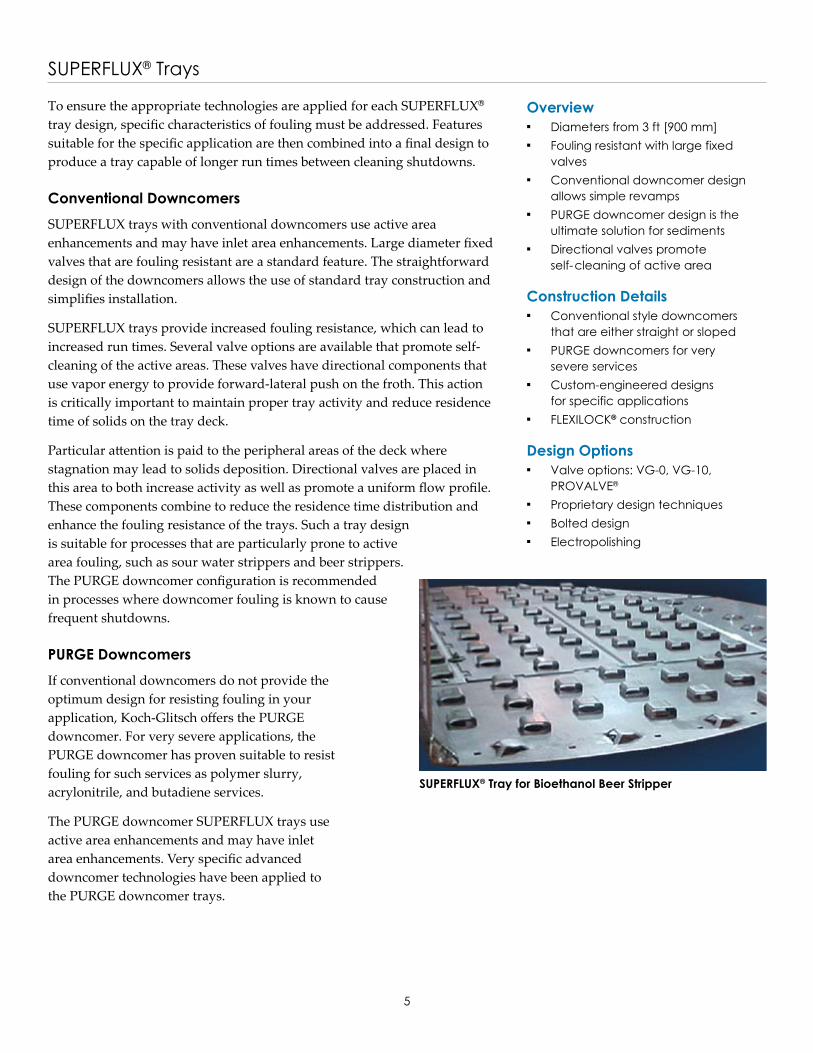
To ensure the appropriate technologies are applied for each SUPERFLUX® tray design, specific characteristics of fouling must be addressed. Features suitable for the specific application are then combined into a final design to produce a tray capable of longer run times between cleaning shutdowns.
Conventional DowncomersSUPERFLUX trays with conventional downcomers use active area enhancements and may have inlet area enhancements. Large diameter fixed valves that are fouling resistant are a standard feature. The straightforward design of the downcomers allows the use of standard tray construction and simplifies installation.
SUPERFLUX trays provide increased fouling resistance, which can lead to increased run times. Several valve options are available that promote self-cleaning of the active areas. These valves have directional components that use vapor energy to provide forward-lateral push on the froth. This action is critically important to maintain proper tray activity and reduce residence time of solids on the tray deck.
Particular attention is paid to the peripheral areas of the deck where stagnation may lead to solids deposition. Directional valves are placed in this area to both increase activity as well as promote a uniform flow profile. These components combine to reduce the residence time distribution and enhance the fouling resistance of the trays. Such a tray design is suitable for processes that are particularly prone to active area fouling, such as sour water strippers and beer strippers. The PURGE downcomer configuration is recommended in processes where downcomer fouling is known to cause frequent shutdowns.
PURGE DowncomersIf conventional downcomers do not provide the optimum design for resisting fouling in your application, Koch-Glitsch offers the PURGE downcomer. For very severe applications, the PURGE downcomer has proven suitable to resist fouling for such services as polymer slurry, acrylonitrile, and butadiene services.
The PURGE downcomer SUPERFLUX trays use active area enhancements and may have inlet area enhancements. Very specific advanced downcomer technologies have been applied to the PURGE downcomer trays.
SUPERFLUX® Tray for Bioethanol Beer Stripper

6
Conventional Downcomer SUPERFRAC® Trays
Multi-pass Downcomer SUPERFRAC® Trays
Characteristics Diameters from 3 ft [900 mm] Fouling resistant with large diameter fixed valves Downcomer design provides simple revamps No extra active area over conventional designs
Construction Details Conventional-style downcomers that are either straight or sloped Custom designs for specific application requirements FLEXILOCK® construction
Design Options Valve options: VG-0, VG-10, PROVALVE®, MV-1, and CRV Optimized liquid push Bubble promoters Bolted design
Characteristics Diameters from 13 ft [3962 mm] High liquid rates Multiple downcomer designs
Construction Details Truncated or multi-chordal downcomer design Custom designs for specific application requirements FLEXILOCK construction Bubble promoters
Design Options Valve options: VG-0, VG-10, PROVALVE, MV-1, and CRV Optimized liquid push Customized downcomer design Proprietary design techniques Bolted design
Conventional downcomer SUPERFRAC® trays use active area enhancementsand may include inlet area enhancements. Refer to page 3 for additionaldescriptions of enhancements.
The straightforward design of the downcomers allows use of standard trayconstruction and simplifies installation, which may allow a lower costsolution.
Some improvements in capacity and efficiency are possible over conventionaltrays by changing the active areas. In some cases, the higher capacity valvesand optimized liquid push can achieve revamp goals without downcomermodifications.
In larger diameter columns, typical multi-pass designs are limited to fourpasses. However, for applications that require more than four passes, theproprietary multi-pass downcomer design can be used to reduce weir loading and improve the capacity of the column.
Koch-Glitsch has successfully designed large diameter columns that use these multi-pass design techniques in 6-pass or 8-pass configurations. Modest capacity increases with these trays are possible in comparison to the best designed 4-pass SUPERFRAC trays.
The downcomer configuration for a multi-pass design typically is the multichordal design; however, virtually any other configuration can be used.
Downcomer Selection
7
Truncated Downcomer SUPERFRAC® Trays
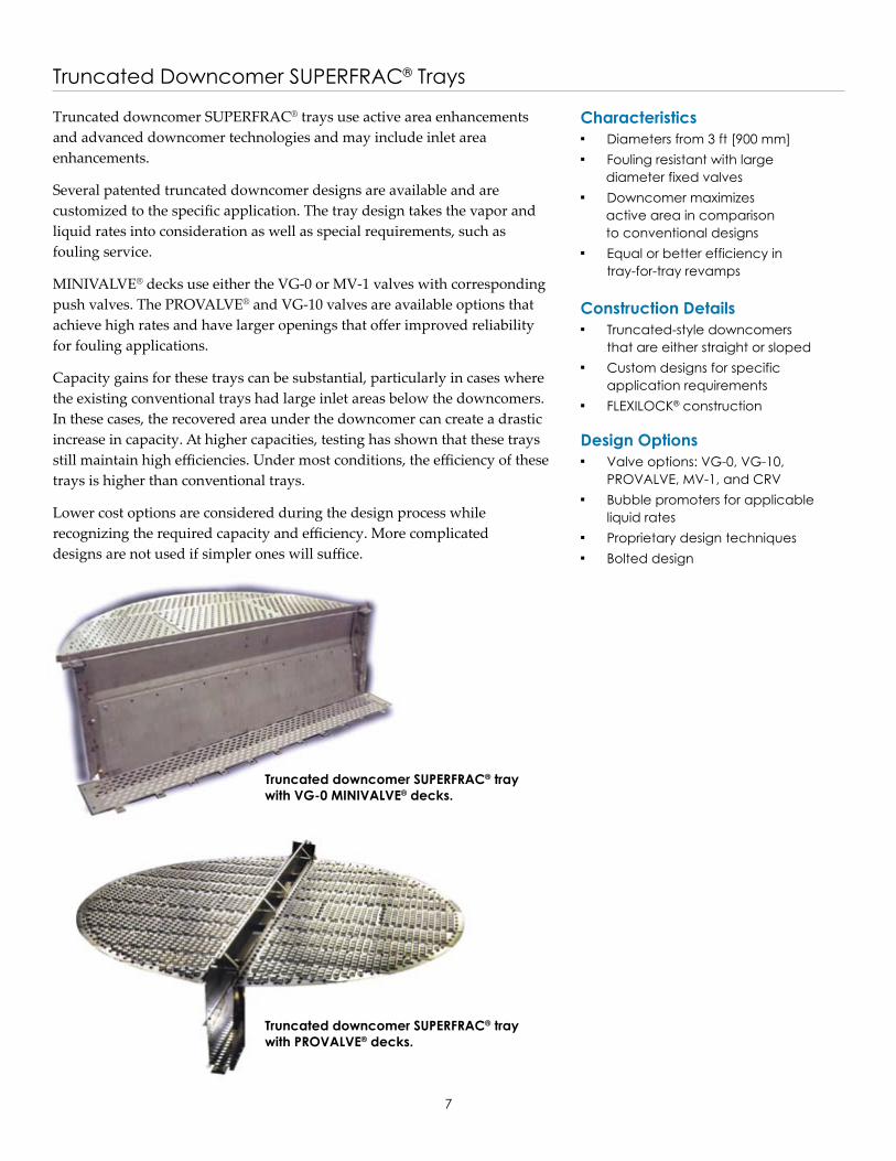
Truncated downcomer SUPERFRAC® trays use active area enhancements and advanced downcomer technologies and may include inlet area enhancements.
Several patented truncated downcomer designs are available and arecustomized to the specific application. The tray design takes the vapor andliquid rates into consideration as well as special requirements, such as fouling service.
MINIVALVE® decks use either the VG-0 or MV-1 valves with correspondingpush valves. The PROVALVE® and VG-10 valves are available options thatachieve high rates and have larger openings that offer improved reliability for fouling applications.
Capacity gains for these trays can be substantial, particularly in cases wherethe existing conventional trays had large inlet areas below the downcomers.In these cases, the recovered area under the downcomer can create a drasticincrease in capacity. At higher capacities, testing has shown that these traysstill maintain high efficiencies. Under most conditions, the efficiency of thesetrays is higher than conventional trays.
Lower cost options are considered during the design process whilerecognizing the required capacity and efficiency. More complicated designs are not used if simpler ones will suffice.
Truncated downcomer SUPERFRAC® tray with VG-0 MINIVALVE® decks.
Truncated downcomer SUPERFRAC® tray with PROVALVE® decks.
Characteristics Diameters from 3 ft [900 mm] Fouling resistant with large diameter fixed valves Downcomer maximizes active area in comparison to conventional designs Equal or better efficiency in tray-for-tray revamps
Construction Details Truncated-style downcomers that are either straight or sloped Custom designs for specific application requirements FLEXILOCK® construction
Design Options Valve options: VG-0, VG-10, PROVALVE, MV-1, and CRV Bubble promoters for applicable liquid rates Proprietary design techniques Bolted design

8
Multi-chordal Downcomer SUPERFRAC® Trays
Characteristics Diameters from 3 ft [900 mm] Design maximizes active area over conventional designs Downcomer design uses entire tray space Equal or better efficiency in tray-for-tray revamps
Construction Details Multi-chordal style side downcomers Custom designs for specific application requirements FLEXILOCK® construction
Design Options Valve options: VG-0, VG-10, PROVALVE®, MV-1, and CRV Optimized liquid push Bubble promoters for applicable liquid rates Proprietary design techniques Bolted design
The patented multi-chordal downcomer SUPERFRAC® tray uses activearea enhancements and advanced downcomer technologies and mayinclude inlet area enhancements.
The multi-chordal downcomer design uses the full vertical tray space, which minimizes downcomer limitations.
In this design, the bottom downcomer area is located over the traysupport ring, thereby using an area that cannot be used as an active area.
Capacity gains for these trays can be substantial, particularly in caseswhere the existing conventional trays had large inlet areas below thedowncomers. At higher capacities, testing has shown that these trays maintain high efficiencies. Generally, the efficiency of these trays is higher than conventional trays.
The multi-chordal shape of the side downcomer at the bottomprovides additional benefits. Equalized liquid flow patterns across the tray Increased flow path length Increased vapor-liquid contact time Improved efficiency Increased bubbling area and tray capacity
The shape of the multi-chordal downcomer allows a conversionfrom straight to sloped downcomers without the use of downcomeradapter bars. This saves the extra cost of the adapters and the fieldtime needed to install them. It also eliminates the need to weld tothe vessel shell.
MINIVALVE® decks use either the VG-0 or MV-1 valves withcorresponding push valves.
The forward-lateral push provided by the optimized liquid pushdesign promotes uniform liquid and vapor distribution across theentire tray deck. This suppresses jet flooding and permitsoperation at higher flow rates. The typical liquid recirculationfound on most conventional trays results in lower efficiency andcapacity. This liquid recirculation is eliminated with theappropriate liquid push design.
Capacity gains for SUPERFRAC® trays can besubstantial while still maintaining high efficiencies.
Liquid flow distribution comparison betweenconventional trays with truncated downcomersand a multi-chordal SUPERFRAC® tray.
Liquid Flux
SUPERFRAC - MCD Tray
Conventional Valve Tray
Conventional Tray SUPERFRAC™ Tray
9
PLUS Technology for SUPERFRAC® Trays
Application - EDC Heavy Ends Column Revamp
Overview Diameters from 3 ft [900 mm] Applications with low liquid rates Available with most downcomer designs
Construction Details Fits most SUPERFRAC tray configurations Designs for specific application requirements Installed below tray deck FLEXILOCK® construction
Design Options Valve options: VG-0, VG-10, PROVALVE®, MV-1, and CRV Optimized liquid push Bubble promoters for applicable liquid rates Proprietary design techniques Bolted design
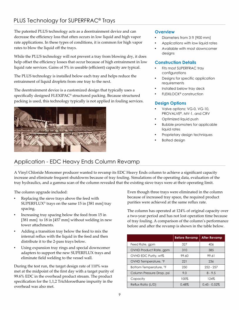
The patented PLUS technology acts as a deentrainment device and can decrease the efficiency loss that often occurs in low liquid and high vapor rate applications. In these types of conditions, it is common for high vapor rates to blow the liquid off the trays.
While the PLUS technology will not prevent a tray from blowing dry, it does help offset the efficiency losses that occur because of high entrainment in low liquid rate services. Gains of 5% in useable (efficient) capacity are typical.
The PLUS technology is installed below each tray and helps reduce the entrainment of liquid droplets from one tray to the next.
The deentrainment device is a customized design that typically uses a specifically designed FLEXIPAC® structured packing. Because structured packing is used, this technology typically is not applied in fouling services.
A Vinyl Chloride Monomer producer wanted to revamp its EDC Heavy Ends column to achieve a significant capacity increase and eliminate frequent shutdowns because of tray fouling. Simulations of the operating data, evaluation of the tray hydraulics, and a gamma scan of the column revealed that the existing sieve trays were at their operating limit.
The column upgrade included: Replacing the sieve trays above the feed with SUPERFLUX® trays on the same 15 in [381 mm] tray spacing. Increasing tray spacing below the feed from 15 in [381 mm] to 18 in [457 mm] without welding in new tower attachments. Adding a transition tray below the feed to mix the internal reflux with the liquid in the feed and then distribute it to the 2-pass trays below. Using expansion tray rings and special downcomer adapters to support the new SUPERFLUX trays and eliminate field welding to the vessel wall.
During the test run, the target design rate of 110% was met at the midpoint of the first day with a target purity of 99.6% EDC in the overhead product stream. The product specification for the 1,1,2 Trichloroethane impurity in the overhead was also met.
Even though three trays were eliminated in the column because of increased tray space, the required product purities were achieved at the same reflux rate.
The column has operated at 124% of original capacity over a two-year period and has not lost operation time because of tray fouling. A comparison of the column’s performance before and after the revamp is shown in the table below.
Before Revamp After Revamp
Feed Rate, gpm 327 406
OVHD Product Rate, gpm 310 385
OVHD EDC Purity, wt% 99.60 99.61
OVHD Temperature, oF 221 236
Bottom Temperature, oF 250 252 - 257
Column Pressure Drop, psi 9.0 8 - 9.5
Capacity 100% 124%
Reflux Ratio (L/D) 0.48% 0.45 - 0.52%
10
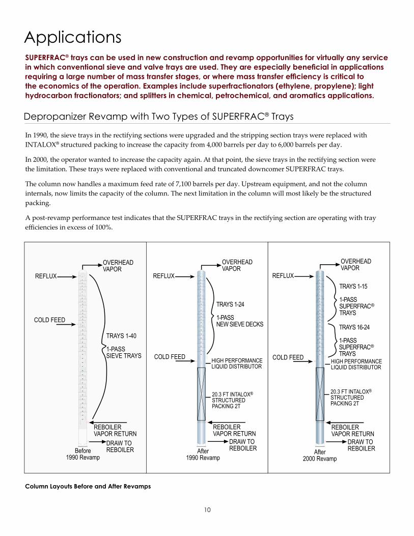
Depropanizer Revamp with Two Types of SUPERFRAC® Trays
In 1990, the sieve trays in the rectifying sections were upgraded and the stripping section trays were replaced withINTALOX® structured packing to increase the capacity from 4,000 barrels per day to 6,000 barrels per day.
In 2000, the operator wanted to increase the capacity again. At that point, the sieve trays in the rectifying section werethe limitation. These trays were replaced with conventional and truncated downcomer SUPERFRAC trays.
The column now handles a maximum feed rate of 7,100 barrels per day. Upstream equipment, and not the columninternals, now limits the capacity of the column. The next limitation in the column will most likely be the structuredpacking.
A post-revamp performance test indicates that the SUPERFRAC trays in the rectifying section are operating with trayefficiencies in excess of 100%.
ApplicationsSUPERFRAC® trays can be used in new construction and revamp opportunities for virtually any service in which conventional sieve and valve trays are used. They are especially beneficial in applications requiring a large number of mass transfer stages, or where mass transfer efficiency is critical to the economics of the operation. Examples include superfractionators (ethylene, propylene); light hydrocarbon fractionators; and splitters in chemical, petrochemical, and aromatics applications.
Column Layouts Before and After Revamps
23
30
29
28
27
26
25
24
22
21
7
20
19
18
17
16
15
14
13
12
11
10
9
8
6
5
4
3
2
1
23
24
22
21
7
20
19
18
17
16
15
14
13
12
11
10
9
8
6
5
4
3
2
1
40
39
38
37
36
35
34
33
32
31
REFLUX
COLD FEED
Before1990 Revamp
OVERHEADVAPOR
TRAYS 1-40
1-PASSSIEVE TRAYS
REBOILERVAPOR RETURN
DRAW TOREBOILER
REFLUX
After1990 Revamp
TRAYS 1-24
1-PASSNEW SIEVE DECKS
OVERHEADVAPOR
COLD FEED
REFLUX
After2000 Revamp
DRAW TOREBOILER
REBOILERVAPOR RETURN
HIGH PERFORMANCELIQUID DISTRIBUTOR
DRAW TOREBOILER
REBOILERVAPOR RETURN
HIGH PERFORMANCELIQUID DISTRIBUTOR
20.3 FT INTALOX®STRUCTUREDPACKING 2T
20.3 FT INTALOX®STRUCTUREDPACKING 2T
OVERHEADVAPOR
TRAYS 1-15
1-PASSSUPERFRACTRAYS
TRAYS 16-24
1-PASSSUPERFRACTRAYS
®
®
COLD FEED
23
24
22
21
7
20
19
18
17
16
15
14
13
12
11
10
9
8
6
5
4
3
2
1
OVERHEADACCUMULATOR
TRIM CONDENSER
CONDENSER-REBOILER
COMPRESSOR
PROPYLENEDE-ETHANIZER
BOTTOMS
C3
SPLI
TTER
C3
SPLI
TTER
11
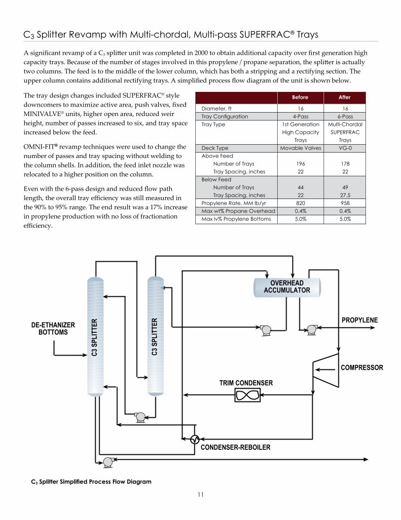
C3 Splitter Revamp with Multi-chordal, Multi-pass SUPERFRAC® Trays
A significant revamp of a C3 splitter unit was completed in 2000 to obtain additional capacity over first generation highcapacity trays. Because of the number of stages involved in this propylene / propane separation, the splitter is actuallytwo columns. The feed is to the middle of the lower column, which has both a stripping and a rectifying section. Theupper column contains additional rectifying trays. A simplified process flow diagram of the unit is shown below.
The tray design changes included SUPERFRAC® styledowncomers to maximize active area, push valves, fixedMINIVALVE® units, higher open area, reduced weirheight, number of passes increased to six, and tray spaceincreased below the feed.
OMNI-FIT® revamp techniques were used to change thenumber of passes and tray spacing without welding tothe column shells. In addition, the feed inlet nozzle wasrelocated to a higher position on the column.
Even with the 6-pass design and reduced flow pathlength, the overall tray efficiency was still measured inthe 90% to 95% range. The end result was a 17% increase in propylene production with no loss of fractionation efficiency.
C3 Splitter Simplified Process Flow Diagram
Before After
Diameter, ft 16 16Tray Configuration 4-Pass 6-PassTray Type 1st Generation Multi-Chordal High Capacity SUPERFRAC Trays TraysDeck Type Movable Valves VG-0Above Feed Number of Trays 196 178 Tray Spacing, inches 22 22Below Feed Number of Trays 44 49 Tray Spacing, inches 22 27.5Propylene Rate, MM lb/yr 820 958Max wt% Propane Overhead 0.4% 0.4%Max lv% Propylene Bottoms 5.0% 5.0%
12
Construction DetailsMetalTrays are available in any formable, weldable sheetmetal material. The most common materials for traysare: Carbon steel Stainless steel, ferritic, austenitic, duplex, martensitic Nickel alloys Copper alloys Titanium, zirconium
Trays are not normally stress relieved or annealed andtypically do not conform to pressure vessel standards.
Trays fabricated from sheet metal materials are typicallysupplied in “as-sheared” condition.
BoltingStandard bolting conforms to AISI specifications. Boltingconforming to ASME® specifications is available upon request.
CertificationMaterial certification is available for all fabricated internals. Positive Material Identification (PMI) testing is available upon request.
GasketingFor multi-piece trays requiring gasketed joints, manychoices of gasket material are available. Where gasketingis required, braided fiberglass tape is supplied as thestandard for linear joints. Depending on the service,KLINGERSIL® C-4401, expanded PTFE, or spiral woundstainless steel with flexible graphite filler gaskets aresupplied as the standard for flanged connections. Othergasket materials are available upon request.
Manway AccessAll trays are designed in sections to pass through vesselmanways. Tower internals are designed to pass througha vessel manway of 18 in [450 mm] minimum insidediameter, unless otherwise specified. Larger manwaysoften provide the ability to optimize the design ofcomponents for faster, easier installation. Please providemanway locations and inside diameters at the time ofinquiry.
Scope of SupplyFor the trays in this brochure, Koch-Glitsch supplies allremovable parts.
The trays do not include vessel attachments for connectionor support, unless specifically stated in the item description.Vessel attachments may be quoted/supplied separately.Examples of attachments that may be required are: Support rings Sump frames Internal flanges at feed inlet nozzles Wall clips for support Downcomer clamping bars Beam seats
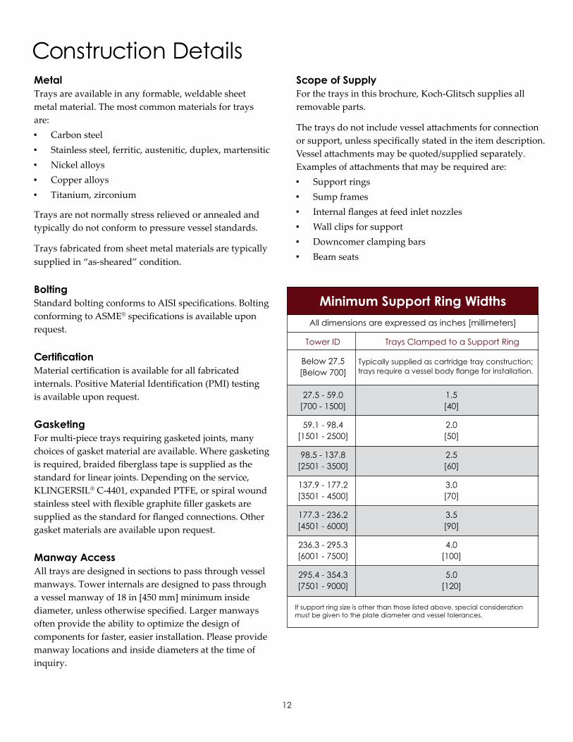
Minimum Support Ring WidthsAll dimensions are expressed as inches [millimeters]
Below 27.5 [Below 700]
27.5 - 59.0 1.5 [700 - 1500] [40]
59.1 - 98.4 2.0 [1501 - 2500] [50]
98.5 - 137.8 2.5 [2501 - 3500] [60]
137.9 - 177.2 3.0 [3501 - 4500] [70]
177.3 - 236.2 3.5 [4501 - 6000] [90]
236.3 - 295.3 4.0 [6001 - 7500] [100]
295.4 - 354.3 5.0 [7501 - 9000] [120]
If support ring size is other than those listed above, special consideration must be given to the plate diameter and vessel tolerances.
Tower ID Trays Clamped to a Support Ring
Typically supplied as cartridge tray construction;trays require a vessel body flange for installation.

13
Feed DevicesObtaining desired tower performance requires the proper handling of liquid and vapor entering the column. The types of feeds or inlets into a column can generally be classified into three major categories: Liquid only (contains less than 1% of vapor by volume) Mixed liquid and vapor, flashing or suppressed flash Vapor
Liquid-Only FeedsAmong the factors that Koch-Glitsch engineers consider when designing a liquid feed device are: Type of tray Expected tray performance Flow rate Operating range Degree of sub-cooled liquid Requirements for mixing
Liquid-Vapor and Flashing FeedsFor mixed liquid-vapor or flashing feeddevices above a tray, the selectiondepends on: Tray type Liquid and vapor flow rates Turndown Column height needed for disengagement and vapor distribution Requirements for mixing
In all cases, separating the vapor andthe liquid phases is a primary concern.In some cases, the requirements foradditional pre-distribution may altercertain tray designs..
Vapor-Only FeedsTwo factors must be considered whenchoosing the proper device for avapor-only feed. The kinetic energy of the inlet vapor in relation to the pressure drop across the trays, the feed nozzle arrangement, and the tower separation requirements. If there is a large difference in the composition and/or temperature between the inlet vapor stream and bulk vapor flow, mixing the two vapors optimizes the performance of the trays.
Specific equipment for vapordistribution may not be required ifsufficient column height is available forequalization or if the pressure dropacross the trays is sufficient to provideproper vapor distribution.
Selection CriteriaThe selection criteria for each category of feed device is unique. Please consult with a Koch-Glitsch technical representative for recommendations.
CFD ModelingGood vapor distribution is essential toachieve superior separation efficiency.Poor vapor distribution is often a majorsource of problems.
Koch-Glitsch combines modernComputational Fluid Dynamics (CFD)modeling technology with its engineering expertise to analyze vapor and liquid distribution when evaluating the performance of existing equipment and developing new, improved designs. This involves computer modeling of the3-dimensional configuration of thecolumn internals to provide detailedpredictions of fluid flow (velocity profiles and so forth) as shown in the figure below.
Koch-Glitsch offers CFD services for the following tasks: Development and optimization of new mass transfer equipment Troubleshooting or analysis of existing equipment Confirmation of equipment designs prior to fabrication and installation
CFD Study for Single VG-0 Valve
(Perspective View)X-Velocity: Unequal Legs
14
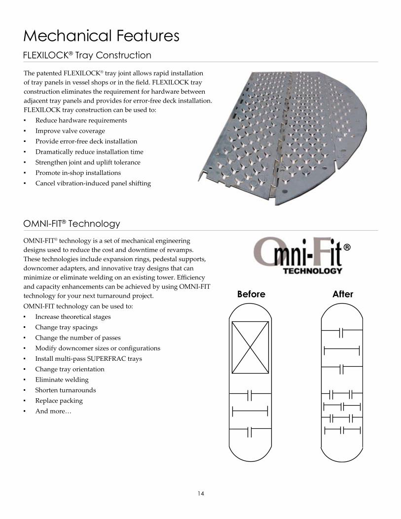
Mechanical FeaturesFLEXILOCK® Tray Construction
The patented FLEXILOCK® tray joint allows rapid installation of tray panels in vessel shops or in the field. FLEXILOCK tray construction eliminates the requirement for hardware between adjacent tray panels and provides for error-free deck installation.FLEXILOCK tray construction can be used to: Reduce hardware requirements Improve valve coverage Provide error-free deck installation Dramatically reduce installation time Strengthen joint and uplift tolerance Promote in-shop installations Cancel vibration-induced panel shifting
OMNI-FIT® Technology
OMNI-FIT® technology is a set of mechanical engineering designs used to reduce the cost and downtime of revamps. These technologies include expansion rings, pedestal supports, downcomer adapters, and innovative tray designs that can minimize or eliminate welding on an existing tower. Efficiency and capacity enhancements can be achieved by using OMNI-FIT technology for your next turnaround project.OMNI-FIT technology can be used to: Increase theoretical stages Change tray spacings Change the number of passes Modify downcomer sizes or configurations Install multi-pass SUPERFRAC trays Change tray orientation Eliminate welding Shorten turnarounds Replace packing And more…
Before After
®

15
HORIZON® Technology
HORIZON® technology is a set of mechanical construction techniques developed specifically for in-shop installation of trays with the vessel in the horizontal position. The patented FLEXILOCK tray construction from Koch-Glitsch is the primary building block of the HORIZON technology. If you plan to shop-install trays, then you need the capabilities provided by HORIZON technology.
Special mechanical design helps prevent inefficient installation sequencing, part deforming/breaking, panel shifting, joint dislodging, extra field inspecting, and field readjusting of tray parts. Installation in the shop versus in the field helps reduce installation costs, accommodates short turnaround schedules, and reduces space constraints involved with manhole access and off-shore platform installations.
Tray Maintenance ServicesComprehensive services for turnarounds and shutdowns.
Downtime is critical for both planned and unplanned turnarounds. Koch-Glitschis available 24/7 to offer equipment and comprehensive support and services toget your tower up and running as quickly as possible. Our response teams arestrategically located around the world and are ready to serve you at any time.
Services include: Inspection Hardware trailers and lockers AHOP® Automated Hardware Ordering Program Equipment Support Services (ESS) technicians
Combined with Koch Specialty Plant Services, Koch-Glitsch goes a step further with its ability to deliver unique, value-driven turnkey equipment and installation solutions to provide faster, safer revamps, which often result in shorter duration turnarounds.
Emergency DeliveryEmergencies happen . . . Koch-Glitsch has a wide variety of products to provide optimum performance whatever the application. Many common materials are in stock, and equipment can be quickly manufactured to meet your requirements regardless of original equipment manufacturer.
With manufacturing facilities and warehouses strategically located worldwide, Koch-Glitsch leads the industry with its on-time performance for delivery of emergency trays and hardware, packing and internals, and mist elimination equipment.
For emergencies, call the Hotline of your nearest Koch-Glitsch office: In the USA and Latin America, call 1-888-KOCH-911 (mass transfer), 1-316-207-7935 (mist elimination), or your local Koch-Glitsch office. In Canada, call 1-905-852-3381 (Uxbridge, Ontario). In Europe, call +39-06-928-911 (Italy), +44-1782- 744561 (UK), or your local Koch-Glitsch office. In Asia, call +65-6831-6500 (Singapore) or your local Koch-Glitsch office.

Bulletin KGSF-02. Rev. 3-2015. Printed in USA. © 2006-2015. Koch-Glitsch, LP. All rights reserved.
Koch-Glitsch Corporate OfficesWorldwide HeadquartersKoch-Glitsch, LP4111 East 37th Street North Wichita, KS 67220 - United States tel: (316) 828-5110 fax: (316) 828-7985
EuropeKoch-Glitsch Italia S.r.l.Via Torri Bianche, 3A 20871 Vimercate MB - Italy tel: +39-039-6386010 fax: +39-039-6386011
For a complete list of our offices and facilities, visit us on the Web at www.koch-glitsch.com.
TrademarksThe following registered trademarks are owned by Koch-Glitsch, LP in the United States and may be registered in other jurisdictions: AHOP® Automated Hardware Ordering Program, FLEXILOCK® tray construction, FLEXIPAC® structured packing, HORIZON® technology, INTALOX® structured packing, KOCH-GLITSCH® technology, “K” KOCH-GLITSCH (logo), MINIVALVE® tray, OMNI-FIT® technology, PROVALVE® tray, SUPERFLUX® tray, SUPERFRAC® tray and ULTRA-FRAC® tray. The following trademarks are owned by Koch-Glitsch, LP in the United States and may be registered in other jurisdictions: KITTEL tray, PLUS technology, PURGE downcomer, and YOU CAN RELY ON US. All other trademarks, service marks, or registered trademarks that appear in this document are the trademarks or service marks of their respective owners.
For related trademark information, visit http://www.koch-glitsch.com/trademarks.
PatentsThe following technologies are protected by one or more patents in the USA; other foreign patents may be relevant: FLEXILOCK® tray construction (US6592106), KITTEL trays (US7028995), Mini Bubble Promoter (USD650466), OMNI-FIT® technology (US6736378, US7055810, US7125005), PLUS technology (US5762668), PROVALVE® tray (US5762834), SUPERFLUX® tray (US5895608), and SUPERFRAC® tray (US5762668, US5895608, US5632935).
Legal NoticeThe information contained in this bulletin is believed to be accurate and reliable, but is not to be construed as implying any warranty or guarantee of performance.
AsiaKoch Chemical Technology Group Singapore Pte. Ltd. 260 Orchard Road, #11-01/09 Singapore 238855 tel: +65-6831-6500 fax: +65-6835-2031The Heeren
Koch-Glitsch (a division of Koch Chemical Technology Group India Pvt. Ltd.)10th Floor, Corporate Park II Chembur, Mumbai 400 071 - India tel: +91-22-6771-7171 fax: +91-22-6771-7161Sion-Trombay Roa
United States/Latin America:
Canada:
Europe/Middle East/Africa:
Asia:
1-888-KOCH-911 (mass transfer), 1-316-207-7935 (mist elimination), or your local Koch-Glitsch office.
1-905-852-3381 (Uxbridge, Ontario).
+39-06-928-911 (Italy), +44-1782-744561 (UK), or your local Koch-Glitsch office.
+65-6831-6500 (Singapore) or your local Koch-Glitsch office.
Emergency Numbers