superdew 3 operating instructions - shaw moisture meters · keypad. the user friendly software uses...
TRANSCRIPT

Superdew 3Hygrometer
Operating InstructionsIssue_0114

EC Declaration of Conformity

Contents
1.0 2.03.0
4.0
5.0
6.07.08.0
9.0
10.011.0
12.013.014.015.016.017.018.019.020.021.022.023.024.0
Unpacking your Shaw Moisture Meters Superdew 3 ................................... 4General Information .................................................................................... 5Safety Information ...................................................................................... 6 3.1 Warning ................................................................................................ 6 3.2 Isolation ................................................................................................ 6Installation .................................................................................................. 7 4.1 Installing the Instrument to the Panel .................................................. 7 4.2 Instrument Wiring ................................................................................ 7 4.3 Power Supply ........................................................................................ 8 4.4 Alarm and Output Cable Connectors .................................................... 8 4.5 Sensor Cable ......................................................................................... 8Installing the Air/Gas Sampling System ....................................................... 9 5.1 Piping Installation Schematic .............................................................. 10 5.2 Piping Schematic Component Index ................................................... 11Installing and Commissioning the Sensor ................................................... 12Default Instrument Configuration .............................................................. 13Programming the Superdew 3 ................................................................... 13 8.1 Principle of Entering Numerical Data ................................................. 13Configuring the Superdew 3 ...................................................................... 14 9.1 rAngE .................................................................................................. 14 9.2 oUtPt .................................................................................................. 15 9.3 AL1 and AL2 ........................................................................................ 16 9.4 rS485 (Communications) .................................................................... 16 9.5 PASS .................................................................................................... 17 9.6 PAnEL .................................................................................................. 17Normal Operation of the Superdew 3 ........................................................ 18Hotkeys ..................................................................................................... 18 11.1 Alarm Keys ........................................................................................ 18 11.2 Units ................................................................................................. 19Calibration (Sensor Ranges up to 0 °C Dewpoint) ....................................... 19Calibration (Sensor Ranges up to +20 °C Dewpoint) ..................................... 20Monitoring the System .............................................................................. 20Faults/Errors ............................................................................................. 21Guarantee ................................................................................................. 21Superdew 3 Specification .......................................................................... 22Appendix A - Superdew 3 Setup Menu Flow Diagram ................................ 23Appendix B - Alarm 1 & 2 Hotkey Flow Diagram ........................................ 24Appendix C - Units Hotkey Flow Diagram ................................................... 25Appendix D - rS485 Protocol ...................................................................... 26Superdew 3 General Assembly Diagram .................................................... 29Sensor Diagram ......................................................................................... 30Sensor Holder Diagram ............................................................................. 30
3

4
1.0 Unpacking your Shaw Moisture Meters Superdew 3
Please examine the Superdew 3 package for any damage or mishandling. If any damage is evident please notify the carrier and the Shaw Moisture Meters representative from where this unit was purchased.
You should have received (if ordered):
1 Superdew 3 instrument1 Shaw sensor1 connecting cable (of the length specified on your order) or 2 metres as standard1 sensor holder1 instruction manual1 pressure dewpoint circular calculator
If anything is missing please contact your distributor immediately.
● ●
●
●● ●
5
2.0 General Information
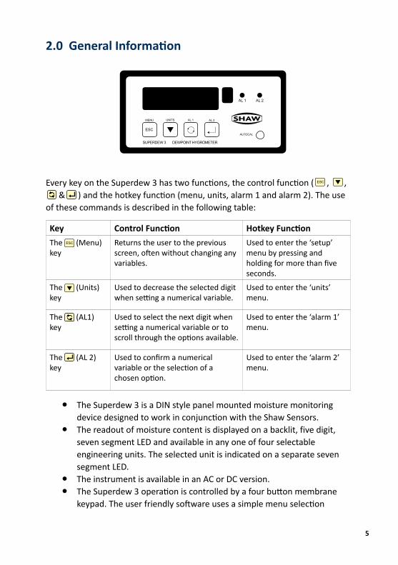
Every key on the Superdew 3 has two functions, the control function ( , , & ) and the hotkey function (menu, units, alarm 1 and alarm 2). The use of these commands is described in the following table:
The Superdew 3 is a DIN style panel mounted moisture monitoring device designed to work in conjunction with the Shaw Sensors.The readout of moisture content is displayed on a backlit, five digit, seven segment LED and available in any one of four selectable engineering units. The selected unit is indicated on a separate seven segment LED.The instrument is available in an AC or DC version.The Superdew 3 operation is controlled by a four button membrane keypad. The user friendly software uses a simple menu selection
Key Control Function Hotkey FunctionThe (Menu) key
Returns the user to the previous screen, often without changing any variables.
Used to enter the ‘setup’ menu by pressing and holding for more than five seconds.
The (Units) key
Used to decrease the selected digit when setting a numerical variable.
Used to enter the ‘units’ menu.
The (AL1) key
Used to select the next digit when setting a numerical variable or to scroll through the options available.
Used to enter the ‘alarm 1’ menu.
The (AL 2) key
Used to confirm a numerical variable or the selection of a chosen option.
Used to enter the ‘alarm 2’ menu.
ESC
●
●
●●
ESC
MENU UNITS AL 1 AL 2
SUPERDEW 3 DEWPOINT HYGROMETER
AL 1 AL 2
AUTOCAL
ESC

6
process and incorporates three hotkeys to enable moisture levels to be read in different units and this allows quick access to both alarm settings.A user controllable security system.The Superdew 3 has an AutoCal potentiometer to perform auto calibration of sensors.The Superdew 3 has two full range alarms that can be set as rising or falling edge triggered. These alarms have visual indication (LEDs) and activate changeover relays for remote indication or control.The Superdew 3 has a fully controllable linear 4 - 20 mA output.The Superdew 3 also has rS485 capabilities, outputs the process variable and unit status when polled.Details of normal operation, engineering unit selection and configuration of the instrument are described within this manual.
3.0 Safety Information
Read the safety information BEFORE installation.
3.1 Warning
Hazardous voltages may be present on instrument terminals. The equipment must be installed by suitably qualified personnel and the instrument must be mounted in a position that provides protection behind the panel to at least IP20.
3.2 Isolation
The power supply terminals and associated internal circuitry are isolated from all other parts of the equipment in accordance with EN61010-1 for connection to a category II supply (pollution degree 2). Any terminals or wiring connected to the input or output, which are accessible in normal operation, must only be connected to signals complying with the requirements for Safety Extra Low Voltage (SELV) circuits.
The mains supply to the instrument must be protected by an external 1-amp fuse and a suitable switch or circuit breaker, which should be near the instrument.
Note: The instrument contains no user serviceable parts.
●●
●
●●
●
7
4.0 Installation
4.1 Installing the Instrument to the Panel
Make a cut-out in the donor panel 138.0 mm x 68.0 mm (DIN 43700).
The maximum panel thickness is 8 mm. If an effective IP65 weatherproof seal is required, the minimum recommended panel thickness is 2.5 mm.
Pass the instrument case through the cut-out in the donor panel and attach the two retaining screws to the studs on either side of the case.
Tighten the retaining screws onto the back of the donor panel until the instrument is clamped securely in position. The screws must be tightened sufficiently to affect a seal between the front of the donor panel and the back of the instrument bezel but never over tightened.
4.2 Instrument Wiring
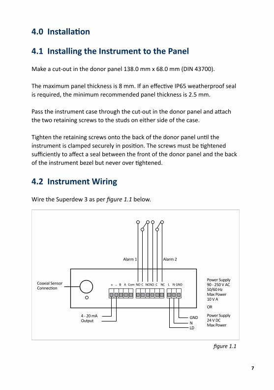
Wire the Superdew 3 as per figure 1.1 below.
Alarm 1 Alarm 2
Coaxial Sensor Connection
4 - 20 mAOutput
GNDNLD
Power Supply90 - 250 V AC50/60 HzMax Power10 V A
OR
Power Supply24 V DCMax Power
+ - B A Com NO C NCNO C NC L N GND
figure 1.1

8
4.3 Power Supply
The Superdew 3 can be powered by either a 90 - 250 V AC or 24 V DC supply. Connect the required supply cable to the appropriate terminals as shown in figure 1.1.
The AC power supply should be between 90 - 250 V AC @ 50/60 Hz.
The power supply wires are retained by screws. Ensure that the exposed section of wire is fully inserted and that no loose strands are exposed.
4.4 Alarm and Output Cable Connectors
Connect the required cables to the appropriate terminals as shown in figure 1.1. Note: The normally open and normally closed relay contact positions and that the correct polarity and the maximum load specification are strictly observed for the analogue outputs.
Ensure that the wire is fully inserted and that no loose strands are exposed.
4.5 Sensor Cable
Connect the sensor coaxial cable into the coaxial socket shown in figure 1.1. Route the sensor cable to the intended site of the sensor.

9
5.0 Installing the Air/Gas Sampling System
The Piping Installation Schematic diagram (see section 5.1) shows all components that could be used in a dry gas measurement application. Not all the items shown will be required for every installation.
Care should be taken to ensure that the sample presented to the measuring sensor is not contaminated with any other component that will damage, contaminate or affect the sensor in a way that will impair the system accuracy.
It is strongly recommended that the sample should not contain particulate matter, oil or other heavy hydrocarbon condensate. If these components contaminate the sample system and/or the measuring sensor, the system response time will be lengthened, although the sensor calibration will not be effected.
The sample must not contain Ammonia, Chlorine, Ozone or any wet acid vapours or liquid as these will permanently damage the sensor and impair calibration accuracy.
The flow rate, although not critical to the sensor measurement, should be low enough to avoid abrasion to the sensor surface without being so low as to extend the system response time to an unacceptable level. In general, a flow rate of between 2 and 3 litres/min at NTP will give the right balance.
The sensor is a variable capacitor, which is directly affected by changes in partial pressure of water vapour and these changes that are proportional to the dew/frost point temperature are displayed on the instrument indicator.
The measuring sensor can be installed directly into the process line but this does create problems with access for maintenance and calibration. It is for these reasons that we recommend that the sensor will be installed in a bypass, fast loop or total loss sample system where the sensor is accessible without interrupting the main process flow line.

10
5.1 Piping Installation Schematic
MAINPROCESS
LINE 4B
P
354A 6
10
11
2
1
9
8
Notesa. The sample pipe should be on the upper surface of the horizontal pipe or on a vertical section of pipe wherever possible.b. The sample tube should run continually upwards from the sample point. If this is not possible then an inspection port or drain tap should be installed at the lowest point in the system.
7

11
5.2 Piping Schematic Component Index
Sample Isolation Valve - This is a recommended item as it allows access to the sample system without interrupting the main process line.Filter Unit – A filter unit is recommended when the samples are likely to contain particulate matter. If the air/gas sample contains heavy hydrocarbon condensate, the filter must be of the coalescing type with a drain. The filter unit should be positioned as close to the sample point as practical.Sample Tube – This should be stainless steel for dry air or gas applications but copper or carbon steel can be used where wetter gases are to be measured. If any section of the sample tube must be flexible then PTFE should be used. In most cases, 3 mm OD (1/8”) is sufficient as it provides good system response time within minimum flow. 6 mm OD (1/4”) tube can be used where pressure drops are too high.Pressure Reduction Valve or Pressure Regulator – If the sample is to be measured at atmospheric pressure then the valve 4A should be fitted and 4B omitted from the system. If the sample is to be measured at full line pressure and the exhaust vented to atmosphere, then valve 4B should be fitted and 4A omitted from the system. If measurements are to be taken at full line pressure and the sample is to be returned to a part of the main line or a vent, which is at a pressure higher than atmospheric, and the input to that line needs a controlled pressure then both 4A and 4B will be required. Sample Pressure Gauge – This is not a critical part of the moisture measurement but may be required if dew/frost point measurements are to be made at higher than atmospheric pressure.Measuring SensorSensor HolderDesiccant Chamber – This item is required when the sampling is to be intermittent. When installed it prevents the ingress of wet air to the sample system, while the sample is not flowing, improving the response time.Flow Control Valve – This can be a separate item or combined with the flow indicator.Flow Indicator – The recommended sample flow is 2 to 3 SL/M.Sample Exhaust – The exhaust can be vented to atmosphere or returned to the process line as discussed above.
1.
2.
3.
4.
5.
6.7.8.
9.
10.11.
12
6.0 Installing and Commissioning the Sensor
It is advisable to carry out an initial purge routine of the sample loop before installing the sensor. This is to remove the possibility of sensor damage on start up.
Refer to the Piping Installation Schematic in section 5.1.
Open the inlet isolation valve slowly until a small flow of air/gas (at atmospheric pressure) flows through the inlet pipe work to the sensor holder, exhausting through the sensor entry port of the sensor holder.
Allow this purge to continue for about 15 to 20 minutes to remove any residual moisture from the sample pipe work and components.
Close the inlet isolation valve and install the sensor into the sensor holder. Locate and connect coaxial cable in position on the sensor.
Open the inlet valve slowly, by opening all valves after the sensor holder, allow a low pressure purge through the whole sample system.
Note: If a closed by-pass loop is installed, this section of the procedure is not possible. Set the required flows within the sample loop.
This completes the installation and commissioning but on initial start up, it could take several hours for the system to reach equilibrium. The Superdew 3 will now indicate the dewpoint of the air/gas surrounding the sensor and the analogue output would be giving mA signals proportional to the indicated dewpoint.

13
7.0 Default Instrument Configuration
The standard factory settings are as follows: ● The instrument will display the moisture content in °C dewpoint ● Both alarms are set to trigger when rising above the upper limit ● The output span is set to 4 - 20 mA ● The 4 - 20 mA output is set to the full span of the selected range e.g. 4 mA = -80 °C 20 mA = 20 °C ● All security codes are defaulted to 0000
8.0 Programming the Superdew 3
8.1 Principle of Entering Numerical Data
See Appendix A, B & C for flow charts.
The key allows the user to leave a part of the menu without changing any settings.
Wherever a numerical value has to be entered into the Superdew 3 the following text will be found. “Use the , & keys to enter……”. The basic principle used to enter numerical values (integer or floating point) is described here.
The first character of the LCD display flashes to indicate it is active. Use the key to select the required number between 0 and 9 (plus the minus sign) then press the key to make the second character flash. Again, use the key to select the required number between 0 and 9, press the key to make the third character flash etc.. Continue this process until all characters are entered. In the case of a floating point numbers in lb/MMscf or ppm, pressing the key again makes the decimal point (dp) active. Use the key to position the dp in the required position. Pressing the key at any point confirms the numerical value. °C and °F are fixed to 1 dp.
ESC

14
The Password used within the Superdew 3 is made of four integers and does not use the dp.
To leave the numerical part of this routine without saving, simply press the key.
9.0 Configuring the Superdew 3
See Appendix A.
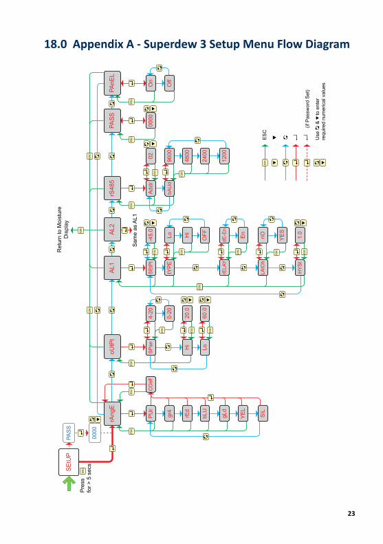
To enter the setup menu press and hold the key for five seconds. This will display the ‘SEtUP’ message on the LED as in the Superdew 3 Setup Menu Flow Diagram (see Appendix A). Pressing the key again enters the setup menu map at the ‘rAngE’ option on the top level. There are seven top level options described.
The default setup will go directly from the SEtUP message to the rAngE screen. However, if the user has set a password, then the user is prompted to enter the correct password before continuing on to the top level.
Most of the screens within the menu have an active 10 second time-out. Therefore, if no keys are pressed within this period the unit reverts automatically to normal operation. In most cases where the 10 second time-out occurs, changes will not have been saved.
9.1 rAngE
The ‘rAngE’ option allows the user to select the required sensor range. This option is used to match the Superdew 3 to the sensor connected to the unit. For example a ‘RED’ sensor requires that the Superdew 3 ‘rAngE’ option ‘rEd’ is selected.
Operation:
Note:
Note:
ESC
ESC
Note:
Note:
Description:

15
While ‘rAngE’ is displayed press the key to enter the subroutine. The display now shows the currently selected sensor range. Use the key to scroll through the options until the required range is displayed. Press the key to select the new range. The message ‘Conf’ will be displayed. Press the key again to confirm selection.
Pressing the key at any time reverts to the ‘rAngE’ screen without saving any change.
See Superdew 3 Specification (pg 22) for detailed information on ranges.
9.2 oUtPt
The ‘oUtPt’ option of the Superdew 3 allows the user to set the span and the range over which the 4 - 20 mA operates. The default setting is for the output to cover the full operating span of the selected range e.g. 4 mA to equal -100 °C and 20 mA to equal 0 °C. It is possible to set a more focused span, such as 4 mA to equal -60 °C and 20 mA to equal -20 °C. It is also possible to select 0 - 20 mA as well as 4 - 20 mA.
While ‘oUtPt’ is displayed press the key to enter the subroutine. The display now displays ‘SPAn’ use the key to select either ‘Hi’, ‘Lo’ or ‘SPAn’ then press the key.
If the key is pressed the Superdew 3 will return to the ‘oUtPt’ screen.
If the ‘SPAn’ option is selected, use the key to select the required span (0 - 20 mA or 4 - 20 mA). Press the key to confirm selection.
If either the ‘Lo’ or ‘Hi’ options are selected the screen will now display the current High or Low range value. Use the & keys to enter the new value. Press the key to confirm and save the new value. The other range limit can now be set by following the same process.
Description:
Operation:
Note:
Operation:
Note:
Note:
ESC
ESC

16
Once the key is pressed to set either the high or low range limit that value is written to memory and will not revert to the previous value even if the 10 second time-out occurs.
9.3 AL1 and AL2
The AL1 and AL2 option allows the user to set up two independent alarms. Trip point, direction of trigger’ relay enable status, latching status and hysteresis can be set within this option.
While ‘AL1’ or ‘AL2’ are displayed press the key to enter the subroutine. The LED now displays ‘SEtPt’. Use the key to select the required function and then press the key.
If the key is pressed the Superdew 3 will return to the ‘AL1’ or ‘AL2’ screen.
Depending on the option selected, the user will now be able to perform the following functions:
Enter the alarm set point.Select if the alarm is to activate on a rising signal ‘Hi’, falling signal ‘Lo’ or ‘OFF’.Select if the relays are energised ‘En’ or de-energised ‘dE-En’Set if the alarm is latch ‘YES’ or not latching ‘nO’.Enter the hysteresis value.
Once the key is pressed to set any of the alarm parameter, that value is written to memory and will not revert to the previous value even if the 10 second time-out occurs.
9.4 rS485 (Communications)
The rS485 option allows the user to set the Superdew 3 address and communication baud rate used when the Superdew 3 is communicating with a PC using rS485 point-to-point communications.
ESC
Note:
Description:
Operation:
Note:
‘SEtPt’‘tYPE’
‘rELAY’‘LAtCh’‘HYSt’
Note:
Description:

17
While ‘rS485’ is displayed press the key to enter the subroutine. The display now displays ‘Addr’ use the key to select either ‘Addr’, or ‘bAUd’ then press the key.
If the key is pressed the Superdew 3 will return to the ‘rS485’ screen.
If the ‘Addr’ option is selected the screen will now display the current address value. Use the & keys to enter the new value. Press the key to confirm and save the new address.
Once the key is pressed to set the address, that value is written to memory and will not revert to the previous value even if the 10 second time-out occurs.
Legal addresses are 1 to 32.
If the ‘bAUd’ option is selected, use the key to select the required baud rate (9600, 4800, 2400 or 1200). Press the key to confirm selection.
For rS485 Protocol please see Appendix B
9.5 PASS
The PASS option allows the user to alter the security password used to protect the ‘SetUP’ menu.
While ‘PASS’ is displayed press the key to enter the subroutine. The LCD now displays ‘0000’. Use the , & keys to enter the new password.
9.6 PAnEL
The PAnEL option allows the user to restrict the functions of the front panel hotkeys. If the ‘On’ option is selected, the hotkeys are unrestricted.
ESC
Operation:
Note:
Note:
Note:
Description
Operation
Description
18
While ‘PAnEL’ is displayed, press the key to enter the subroutine. The LCD now displays ‘On’ or ‘OFF’. Use the key to select ‘On’ or ‘OFF’. Press the key to confirm selection.
10.0 Normal Operation of the Superdew 3
In normal operation, the Superdew 3 will display the current moisture value of the connected sensor. The value is displayed in the currently selected engineering units, which is indicated by the small LED.
The alarm LEDs (AL1 and AL2) will light whenever an alarm condition occurs and only turn off when the alarm condition clears.
Remote signalling of an alarm condition is provided by two internal changeover relays that trigger at the same time as the LEDs.
11.0 Hotkeys
11.1 Alarm Keys
See Appendix C
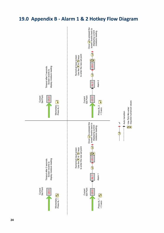
The ‘AL1’ and ‘AL2’ hotkeys allow the user to review and alter the alarm trigger points without interrupting the monitoring process.
If the hotkeys are restricted by the ‘PAnEL’ function then the alarms can only be reviewed.
To review the alarm trip point press the (AL1) or (AL2) key momentarily. The screen will display the set trip point for two seconds before reverting to the dewpoint reading.
To alter the trip point press and hold the (AL1) or (AL2) keys for longer than five seconds. The screen will display and allow the user to alter the trip point using the , & keys.
Operation
Description
Operation
19
11.2 UnitsSee Appendix D
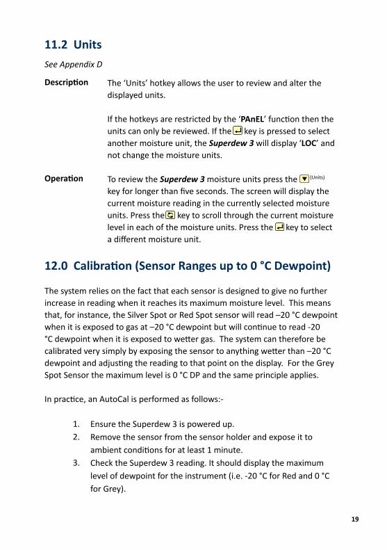
The ‘Units’ hotkey allows the user to review and alter the displayed units.
If the hotkeys are restricted by the ‘PAnEL’ function then the units can only be reviewed. If the key is pressed to select another moisture unit, the Superdew 3 will display ‘LOC’ and not change the moisture units.
To review the Superdew 3 moisture units press the (Units) key for longer than five seconds. The screen will display the current moisture reading in the currently selected moisture units. Press the key to scroll through the current moisture level in each of the moisture units. Press the key to select a different moisture unit.
12.0 Calibration (Sensor Ranges up to 0 °C Dewpoint)
The system relies on the fact that each sensor is designed to give no further increase in reading when it reaches its maximum moisture level. This means that, for instance, the Silver Spot or Red Spot sensor will read –20 °C dewpoint when it is exposed to gas at –20 °C dewpoint but will continue to read -20 °C dewpoint when it is exposed to wetter gas. The system can therefore be calibrated very simply by exposing the sensor to anything wetter than –20 °C dewpoint and adjusting the reading to that point on the display. For the Grey Spot Sensor the maximum level is 0 °C DP and the same principle applies.
In practice, an AutoCal is performed as follows:-
Ensure the Superdew 3 is powered up.Remove the sensor from the sensor holder and expose it to ambient conditions for at least 1 minute.Check the Superdew 3 reading. It should display the maximum level of dewpoint for the instrument (i.e. -20 °C for Red and 0 °C for Grey).
Description
Operation
1.2.
3.
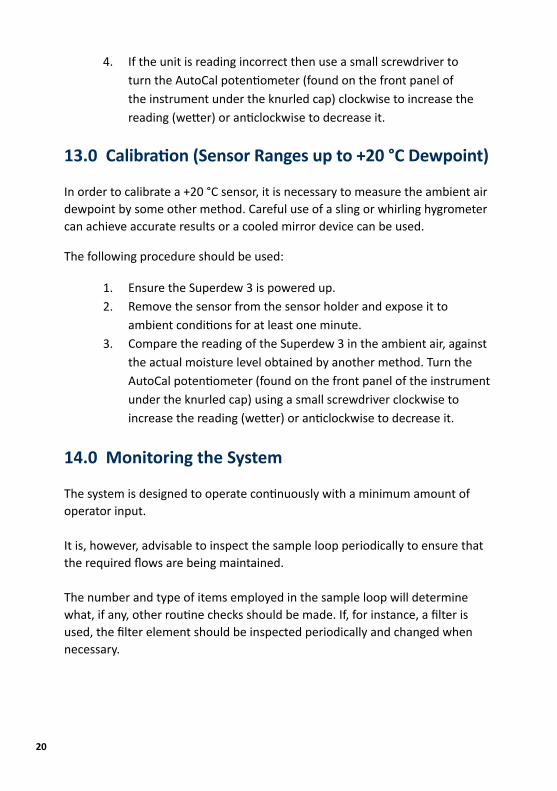
If the unit is reading incorrect then use a small screwdriver to turn the AutoCal potentiometer (found on the front panel of the instrument under the knurled cap) clockwise to increase the reading (wetter) or anticlockwise to decrease it.
13.0 Calibration (Sensor Ranges up to +20 °C Dewpoint)
In order to calibrate a +20 °C sensor, it is necessary to measure the ambient air dewpoint by some other method. Careful use of a sling or whirling hygrometer can achieve accurate results or a cooled mirror device can be used.
The following procedure should be used:
Ensure the Superdew 3 is powered up.Remove the sensor from the sensor holder and expose it to ambient conditions for at least one minute.Compare the reading of the Superdew 3 in the ambient air, against the actual moisture level obtained by another method. Turn the AutoCal potentiometer (found on the front panel of the instrument under the knurled cap) using a small screwdriver clockwise to increase the reading (wetter) or anticlockwise to decrease it.
14.0 Monitoring the System
The system is designed to operate continuously with a minimum amount of operator input.
It is, however, advisable to inspect the sample loop periodically to ensure that the required flows are being maintained.
The number and type of items employed in the sample loop will determine what, if any, other routine checks should be made. If, for instance, a filter is used, the filter element should be inspected periodically and changed when necessary.
4.
1.2.
3.
20

21
The instrument should not require any routine maintenance but if any malfunction is suspected, it is advisable to contact your local dealer.
Should it be necessary at any time or for whatever reason, to change either the instrument or sensor, it should be noted that the components of the Superdew 3 sensor system are completely interchangeable.
15.0 Faults/Errors
If the sensor is short-circuited the display will read ‘Short’, the voltage output will drive to full scale, the current output will drive to 24 mA and both alarms/relays will trip.
If the user tries to enter an alarm level above the maximum value of the sensor range selected, the Superdew 3 will display ‘oVEr’.
16.0 Guarantee
All Shaw products are guaranteed for two years from the date of purchase, some exclusions are as follows:
Removing protective guard from any sensor, subjecting sensor to shock or black list gases e.g. caustic and acidic gases like ammonia and chlorine, tampering with any internal electronics and applying incorrect supply voltage to meters, subjecting to excessive flow rate, contaminants and general misuse.
If you suspect a fault which you feel needs to be attended to under guarantee please contact us for assistance hopefully to help fault find and effect a remedy and if this is not successful to give precise instructions for the return for inspection.
No equipment will be replaced or repaired without having been returned for inspection either to ourselves or an authorised distributor.

22
17.0 Superdew 3 Specification
Transmitter:
Enclosure:
PCB Layout:
Display:
Alarm & Range Limits:
Front Panel:
Power Supplies:
Alarms:
Analogue Outputs:
Temperature Range:
EMC:
Compatible with the Shaw Sensor
DIN Style, 144 mm (w) x 72 mm (h) x 116 mm (d)
General PSU PCB and display PCB to fit the DIN enclosure
Five characters LED display. Largest positive number 99999
Upper Limit Lower Limit°C dewpoint 20.0 -100.0°F dewpoint 68.0 -184.0P (PPM) 9999 0.001L(lb/MMscf) 1000 0.001
A membrane keyboard with four keys and four windows for the four character LCD, the single character seven segment LED and the two alarm LEDs.
Universal 90 - 250 V AC 50/60 Hz or 24 V DC versions.
Two single pole changeover contacts (NO/C/NC), rated at 10 A at 240 V AC. Alarm trip at set point with 0.1 °C (or equivalent) hysteresis to eliminate relay chatter.
Isolated 4 - 20 mA as standard. The span of the outputs can be set by software control.
Electronics -10 °C to +60 °C Sensor -10 °C to +50 °C
Designed to meet the EMC and LVD directives.
23
18.0 Appendix A - Superdew 3 Setup Menu Flow Diagram
SE
tUP
rAng
EoU
tPt
AL1
AL2
rS48
5PA
SS
PAnE
L
PU
r
gr4
rEd
bLU
gLd
YE
L
SiL
CO
nFS
Pan
4-20
SE
tPt
-45.
0A
ddr
0200
00O
n
Off
0-20
tYP
ELo
bAU
d96
00
Hi
20.0
Hi
4800
Lo60
.0O
FF24
00
rELA
YdE
-En
1200
En
LAtC
hnO YE
S
HY
St
1.0
PAS
S
0000
Ret
urn
to M
oist
ure
Dis
play
Pre
ssfo
r > 5
sec
s
Sam
e as
AL1
ESC
ESC
ESC
ESC
ESC
ESC
ESC
ESC
ESC
ESC
ESC
ESC
ESC
ESC
ESC
ESC
ESC
ESC
ESC
ESC
ESC
ESC
ESC
ESC
ES
C
(if P
assw
ord
Set
)
Use
&
to
ent
er
requ
ired
num
eric
al v
alue
s
24
19.0 Appendix B - Alarm 1 & 2 Hotkey Flow Diagram
-20.
0
-20.
0A
L 1
-20.
0-2
0.0
AL
2-2
0.0
-20.
0
Cur
rent
Set P
oint
Tim
eout
afte
r 2 s
econ
ds.
Scre
en re
verts
todi
spla
y m
oist
ure
read
ing
Mom
enta
ryPr
ess
AL 1
Cur
rent
Set P
oint
Pres
s AL
1>
5 se
csAl
arm
1
Num
eric
al in
put s
cree
nU
se th
e
&
key
sto
ent
er th
e ne
w s
et p
oint
Onc
e
is
pre
ssed
the
scre
en re
verts
bac
k to
disp
layi
ng c
urre
ntm
oist
ure
read
ing.
Cur
rent
Set P
oint
Cur
rent
Set P
oint
Mom
enta
ryPr
ess
AL 2
Pres
s AL
2>
5 se
cs
Tim
eout
afte
r 2 s
econ
ds.
Scre
en re
verts
todi
spla
y m
oist
ure
read
ing
Num
eric
al in
put s
cree
nU
se th
e
&
keys
to e
nter
the
new
set
poi
nt
Onc
e
is
pre
ssed
the
scre
en re
verts
bac
k to
disp
layi
ng c
urre
ntm
oist
ure
read
ing.
Alar
m 2
Aut
o tra
nsiti
on
Use
&
to
ent
er
requ
ired
num
eric
al v
alue
s

25
20.0 Appendix C - Units Hotkey Flow Diagram
Pre
ss U
nits
>
5 se
cs
If
is
pres
sed
the
Sup
erde
w re
verts
bac
kto
the
norm
al s
cree
nw
ithou
t cha
ngin
g un
its
Onc
e
is
pre
ssed
the
Sup
erde
w re
verts
bac
k to
the
norm
al s
cree
ndi
spla
ying
moi
stur
e in
the
new
ly s
elec
ted
units
.
Uni
tS
-1.4
29.4
5355
254
°C °F P L
ESC
ES
C
Scr
oll
Ent
er
ESC
26
21.0 Appendix D - rS485 Protocol
Data Collection System Output
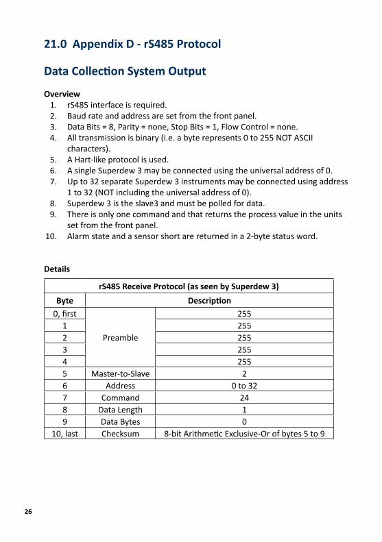
OverviewrS485 interface is required.Baud rate and address are set from the front panel.Data Bits = 8, Parity = none, Stop Bits = 1, Flow Control = none.All transmission is binary (i.e. a byte represents 0 to 255 NOT ASCII characters).A Hart-like protocol is used.A single Superdew 3 may be connected using the universal address of 0.Up to 32 separate Superdew 3 instruments may be connected using address 1 to 32 (NOT including the universal address of 0).Superdew 3 is the slave3 and must be polled for data.There is only one command and that returns the process value in the units set from the front panel.Alarm state and a sensor short are returned in a 2-byte status word.
Details
1.2.3.4.
5.6.7.
8.9.
10.
rS485 Receive Protocol (as seen by Superdew 3)Byte Description
0, first
Preamble
2551 2552 2553 2554 2555 Master-to-Slave 26 Address 0 to 327 Command 248 Data Length 19 Data Bytes 0
10, last Checksum 8-bit Arithmetic Exclusive-Or of bytes 5 to 9

27
rS485 Transmit Protocol (as seen by Superdew 3)Byte Description
0, first
Preamble
2551 2552 2553 2554 2555 Slave-to-Master 66 Return Address 8-bit Arithmetic Or of Address with 1287 Command 248 Data Length 69
Statusbits 15 - 8
10 bits 7 - 011
Data
Process Value12 Single Precision (4-Byte Float)12 IEEE 754 Format14 Big-endian (first byte = ms)
15, last Checksum 8-bit Arithmetic Exclusive-Or of bytes 5 to 14
Transmit StatusBit Description
15, first (ms)
Not defined14131211 Alarm 2: user to clear10 Alarm 1: user to clear9 Alarm 28 Alarm 17 Not defined6 Sensor short5
Not defined
4321
0, last (ls)
28
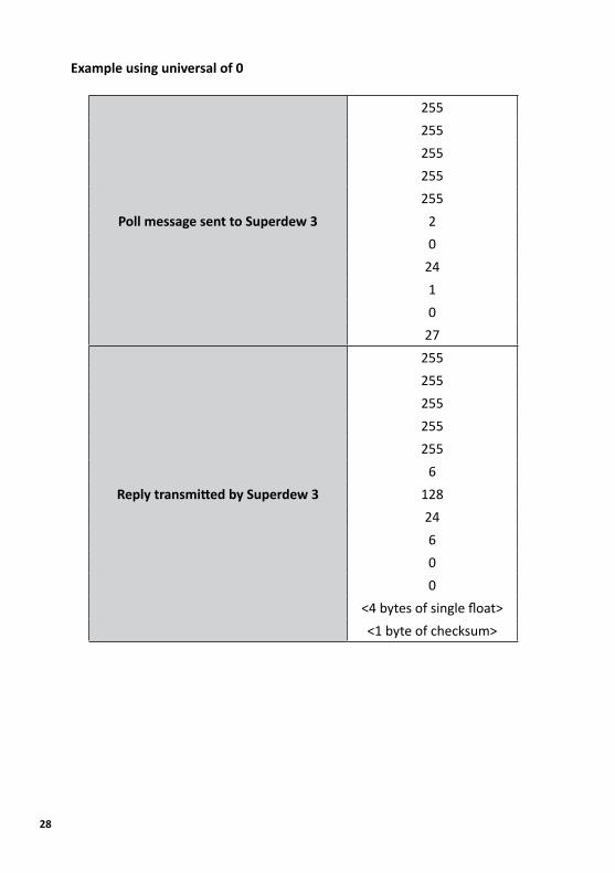
Example using universal of 0
Poll message sent to Superdew 3
255255255255255
20
2410
27
Reply transmitted by Superdew 3
255255255255255
612824600
<4 bytes of single float><1 byte of checksum>
29
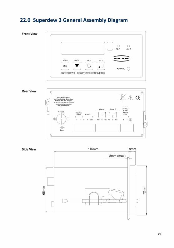
22.0 Superdew 3 General Assembly Diagram
Front View
Rear View
Side View 116mm
8mm (max)
8mm
65m
m
72m
m

30
23.0 Sensor Diagram
24.0 Sensor Holder Diagram
74mm
143mm
M14 x 1.25mm Pitch(7/8”) AF Hex
63mm
NOTE: The assembly is shown with ¼ inch OD tube fittings. The dimension across the tube fittings will vary for all other size fittings.
47 mm (1.85 inch)
34 mm ø (1.34 inch ø) 3 mm (0.125 inch)
4 Mounting Holes 5.5 mm ø (0.22 inch ø)
60 mm (2.36 inch)
46 mm (1.81 inch)
43 mm (1.77 inch) nominal43 mm (1.77 inch) nominal
15 mm
(0.6 inch)
80 mm
(3.15 inch)
90 mm
(3.54 inch)
25 mm
(0.98 inch)
65 mm
(2.56 inch)

Shaw Moisture Meters (UK) Ltd.Len Shaw Building
Bolton LaneBradford BD2 1AF
Englandt. +44 (0)1274 733582f. +44 (0)1274 370151

Shaw Moisture Meters (UK) Ltd. | Len Shaw Building | Bolton Lane | Bradford | BD2 1AF | Englandt. +44 (0)1274 733582 | f. +44 (0)1274 370151 | e. [email protected] | www.shawmeters.com
© SHAW MOISTURE METERS UK (LTD) 2010Superdew 3 Operating_Instructions_Issue _0114