superconducting dc transmission lines for electric …. 75 (2004) pp.207. low thermal conductivity...
TRANSCRIPT

Center of Applied Superconductivity and Sustainable Energy Research
Superconducting DC transmission lines for electric power as energy saving systems
Toshio KawaharaCenter of Applied Superconductivity and Sustainable Energy Research (CASER),
Chubu University

Center of Applied Superconductivity and Sustainable Energy Research
No. 1Global warming and exhausting energy resources
Warming in the world
Ref: IPCC fourth assessment report (2007)
Oil peak
Ref: M.K. Hubbert; American Petroleum Institute (1956).
CO2 come from fossil energy could cause the global warming.
•Energy saving•Change to sustainable natural energy
Heat
greenhouse effect gas

Center of Applied Superconductivity and Sustainable Energy Research
No. 2
Genesis project
Solar power Wind power Solar power works well only at day time.
Sustainable energy can be transferred to the world by power grids to solve this.normal conducting transmission or superconducting (SC) one
Example of SC AC transmissionY. Kuwano; 4th International Photovoltaic Science and Engineering Conference (1989) .H. Kitazawa; Japan and its economical dreams by a scientist (2002) (in Japanese).
(Albany, USA)
wind Solar SC cable

Center of Applied Superconductivity and Sustainable Energy Research
No. 3
SC DC transmission for Ultra long distance
DC has advantage for the long distance.
Superconducting DC transmission
Low lossLow voltage → Low cost?
Base for the actual use of the sustainable energy
ABB Asea Brown Boveri Ltd.; http://www.abb.com/HVDC/.

Center of Applied Superconductivity and Sustainable Energy Research
No. 4
AC transmission
DC equipments at home
Natural energy
DC distributionInternet data center(iDC)
Server works with DC power
AC-DC conversion
Home
Power plant
Future DC transmission
Energy saving and SC transmission
Ultra long distance transmission for the natural energy
Energy super highway using SC-DC transmission
Steam power

Center of Applied Superconductivity and Sustainable Energy Research
No. 5
20 m DC superconducting transmission line
Ingredients for SC transmission lines1. Superconductors2. Cryogenic systems3. Supporting Circuits
Low heat loss and low cost systems should be developed.
DC superconducting transmission line has been constructed in Chubu University
S. Yamaguchi, et al.: J. Phys.: Conf. Ser., Vol. 97 (2008) 012290.
Terminal A Terminal B
DC power supply
Superconducting cable
Measurements terminal box

Center of Applied Superconductivity and Sustainable Energy Research
No. 6
High Tc superconductor materials
Both tapes are useful for transmission and distribution.
1. Y-123 coated conductors: Potentially cheap tapes.
2. Bi-2223 tapes: It seems to be better for cryogenic systems with higher Tc.
There are many superconductors.
Now two kinds of superconductors can be used as high Tc superconductors.

Center of Applied Superconductivity and Sustainable Energy Research
No. 7
Superconducting Cables
Powder in tube (PIT) methods for Bi tapesRef: H. Kitaguchi and H. Kumakura; MRS Bulletin 26 (2001) 121.
Bi Multifilament tape
coated conductors for Y-123
SEI has developed commercial tapes using controlled over-pressure (CT-OP) method.
Several methods could be selected.ex.) CVD (SuperPower Inc.)
MOD (American Superconductor)PLD or evaporation (LANL)
Stabilization layer: Cu, Au etc.
Superconducting layer: Y-123, Gd-123 etc.
Buffer layer: YSZ, Gd2Zr2O7, MgO, CeO2, LaMnO3 etc.Substrate: Hastelloy,
Stainless steel etc.

Center of Applied Superconductivity and Sustainable Energy Research
No. 8
Superconducting AC transmission line
• Normal-conducting AC grid systems are widely used. – Easy to obtain high voltage by a transformer– Easy to break the circuits– No need of expensive UHV AC-DC converters
• Superconducting AC transmission seems to be fit to conventional grid systems with low loss systems.
• However, – There are small AC loss.– 3 cables are required. Then, it is higher cable cost.– Long distance transmission is difficult because of phase
imbalance.

Center of Applied Superconductivity and Sustainable Energy Research
No. 9
AC grid experiments using AC cables
There are many projects in U.S., Korea, Japan etc.

Center of Applied Superconductivity and Sustainable Energy Research
No. 10
AC losses
• Hysteresis loss– Magnetization curve has
hysteresis energy loss.• Coupling loss (Eddy current
loss)– Shielding current should flow
between filaments.– Then, the current goes
through normal metals.
Twisted multifilament conductors have small AC loss.
Hysteresis loss Coupling loss
Current flows in the whole conductorsOptimum region
fc1: inverse of coupling current time constantHp: center reachable magnetic field
F. Sumiyoshi et al.; J. Appl. Phys. 50 (1979) 7044.
Suppose time varying magnetic field is applied to multifilament SC conductors
AC losses
Center of Applied Superconductivity and Sustainable Energy Research
No. 11
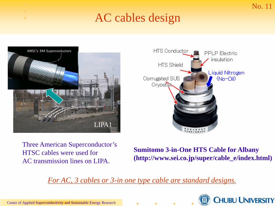
AC cables design
Sumitomo 3-in-One HTS Cable for Albany(http://www.sei.co.jp/super/cable_e/index.html)
Three American Superconductor’s HTSC cables were used for AC transmission lines on LIPA.
For AC, 3 cables or 3-in one type cable are standard designs.
LIPA1

Center of Applied Superconductivity and Sustainable Energy Research
No. 12
DC cable design
図2-2-4 三相一括交流ケーブルと直流ケーブルの断面模式図
Three phase AC cable and DC cable
Advantage of DC as a cryogenic system
1. Simple structure is effective for low cost system.
2. Low heat loss cable with small diameter is high performance in cryogenics.
20 m cables used for superconducting transmission line in Chubu University
40φ
insulation30kVDC
earth layer
formercopper wires
HTS Tape x 39
Simple and small cables are for low cost and high performance systems

Center of Applied Superconductivity and Sustainable Energy Research
No. 13
Cryogenic system
• Heat loss in the cryogenic systems.– Double pipes are most important for large systems.– Terminals are important for small systems. – Cryo-cooler and pumps – small circulation loss of LN2 are required
for actual systems.
Cooler and
pumpLN2
Terminal B
Terminal ACurrent
Double pipes
SC cables
LN2
Schematic pictures for DC transmission lines

Center of Applied Superconductivity and Sustainable Energy Research
No. 14
Emissivity of metals
MaterialsFulk, Reynolds,
Park(1955) T = 300 K and 78K
McAdams(1954)T = 300K
Amano, Ohara(1990, 1991)
T = 300 K and 78 KAl(Polished) 0.02 0.04 0.036~0.04
Al(Oxide) 0.31Brass(Plished) 0.029 0.03Brass(Oxide) 0.6Cu(Polished) 0.015~0.019 0.02 0.06
Cu(Oxide) 0.6 0.30~0.50Cr plate 0.08 0.08Au foil 0.010~0.023 0.02~0.03
Au plate 0.026Ag plate 0.008 0.02~0.03
SUS 0.048 0.074 0.11~0.13
Stainless steel exhibits high Emissivity.

Center of Applied Superconductivity and Sustainable Energy Research
No. 15
Outer; Electro polishing (φ 165)
Iner; Electro polishing (φ 89)
Outer;Electro polishing (φ 140)
Iner; Electro polishing (φ 76)
Inner; Zn plating (φ 89)
Inner;Zn plating (φ 89)+ 3 layers MLI
2)
Ref.) Nasu et al.; Abstracts of CSJ Conference 79 (2008) p.97.
Our pipes are low heat loss compared with Corrugate pipes
Corrugate pipes (Nexans)
0.5W/m
Heat loss reduction in double cryo pipes
Diameter of inner pipe
Hea
t los
s [W
/m]
Small pipes with high reflectivity

Center of Applied Superconductivity and Sustainable Energy Research
No. 16
Low loss systems
• Low loss systems come from cryogenic improvements.Suppose heat leak is 0.5 W/m and 0.3 m/sec, for low pump power condition.
Distance between cooling station 4 km 20 km 100 km
Temperature rise with initial LN2
of 78 K.80 K 88 K 128 K
SC tapes Y tapes are better.
Bi tapes are better. X
Cheap Y tapes can be used. Bi tapes are sufficient or
cryo cooler with COP 0.1@70 K is required for Y tapes.
Larger flow rate or the followings, for example, with slow circulation.1. Slash nitrogen (63 K)2. Heat leak < 0.4 W/m3. Tc ~ 115 K
⊿T ~ 0.5 K/ km

Center of Applied Superconductivity and Sustainable Energy Research
No. 17
Principles of Peltier current lead (PCL)
S. Yamaguchi, et al.: Rev. Sci. Instrum., Vol. 75 (2004) pp.207.
low thermal conductivity and heat pump effects of thermoelectric materials are useful.

Center of Applied Superconductivity and Sustainable Energy Research
No. 18
PCL in the 20 m transmission lines
0
20
40
60
80
100
0 10 20 30 40 50 60 70 80
N-type PCLP-type PCL
Temperature dif
fere
nce
TH-T L[K
]
Current[A]
BiTe alloy(10 x 10x t8 mm)Cu Block
Cu Block
Picture of PCL
TH
TL
Ref.) Fujii et al.; Abstracts of CSJ Conference 79 (2008) p.98.
Center of Applied Superconductivity and Sustainable Energy Research
No. 19
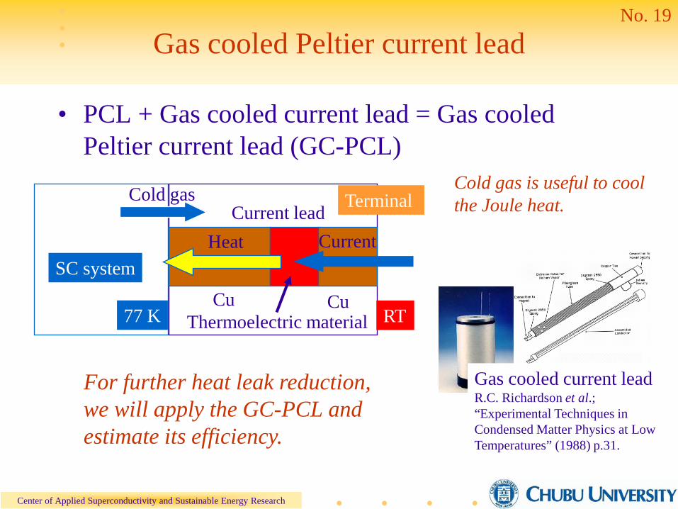
Gas cooled Peltier current lead
• PCL + Gas cooled current lead = Gas cooled Peltier current lead (GC-PCL)
Cu CuThermoelectric material
Heat Current lead Terminal
Cold gas is useful to cool the Joule heat.
Current
RT77 K
SC system
For further heat leak reduction, we will apply the GC-PCL and estimate its efficiency.
Cold gas
Gas cooled current leadR.C. Richardson et al.; “Experimental Techniques in Condensed Matter Physics at Low Temperatures” (1988) p.31.

Center of Applied Superconductivity and Sustainable Energy Research
No. 20
Simulation method
• Temperature distribution on the lead was calculated by the thermal equation.
• Gas cooled conditions-Heat exchange ratio f: 0 ~ 3– f = 0: no gas cooling – Only thermal conductance cools the lead.– f = 1: self cooled – Cold gas and current lead are in thermal equilibrium.– f > 1: over-gas – Cold gas from the total systems comes into the lead.
• The length of the current lead was optimized by the minimum heat leak. Both heat leak and temperature distribution on the lead was calculated.
M. N. Wilson; “Superconducting Magnets” (1983) p.257
0)()(2
=+−
AI
dxdCmf
dxdAk
dxd
pθρθθθ
k: Thermal conductivity, θ: Temperature,Cp: Specific heat, A: Cross section,I: Current, ρ: Resistivity
Seebeck effect (αIθ) is added in the first term (heat flow) for PCL.

Center of Applied Superconductivity and Sustainable Energy Research
No. 21
Heat leak with over-gas conditions
PCL+gas coolingf = 1→17.9 W/kA(37% reduction)
PCL+gas cooling with over gasf = 2→13.5 W/kA(52% reduction)f = 3→11.4 W/kA(60% reduction)
28.5 W/kA
Reduction of heat leak
Heat leak of 15 W/kA
For 30 MW systems with the current of 2 kA,heat leak at terminal could become 0.4 W/m for 200 m.
I = 100 A
Ref.) Kawahara et al.; Abstracts of CSJ Conference 79 (2008) p.138.
10
15
20
25
30
0 0.5 1 1.5 2 2.5 3 3.5
p typen type
Hea
t lea
k (W
/kA
)
Heat exchange ratio f
For p-type,

Center of Applied Superconductivity and Sustainable Energy Research
No. 22
Cost reduction by GC-PCL for iDC
Heat leak in cryo double pipe (0.5 W/m) : 200 W
Heat leak estimation for 400 m, 10 MW (400 V, 25 kA) systems
CCL: 42.5 W/kA ⇒ 1063 W@1 terminal
GC-PCL: 13.5 W/ kA (f = 2) ⇒ 338 W@1 terminalPower loss:
System loss (COP 0.15) is 67 kW@4 terminals
System loss (COP 0.15) is 23 kW@4 terminals
Loss is changed from 0.67 % to 0.23 % by GC-PCL.The cost reduction of electric power is $ 58 k/year ($ 0.15/kW)
This corresponds to $1.1 M at the 5% interest.

Center of Applied Superconductivity and Sustainable Energy Research
No. 23
Summery and future developments
• Heat leak of 0.5 W/m is promising for 4 km transmission by Y tapes and 20 km by Bi tapes.
• Potentially low cost Y coated conductors can be used for short length applications.
• Higher Tc Bi tapes are better for long distance transmission such as under water transmission.
Improvements of terminals such as PCL are highly required for higher performance applications.
Total improvements of cryo double pipes, high performance cryo cooler, and stable high Tc cables are required.
Center of Applied Superconductivity and Sustainable Energy Research
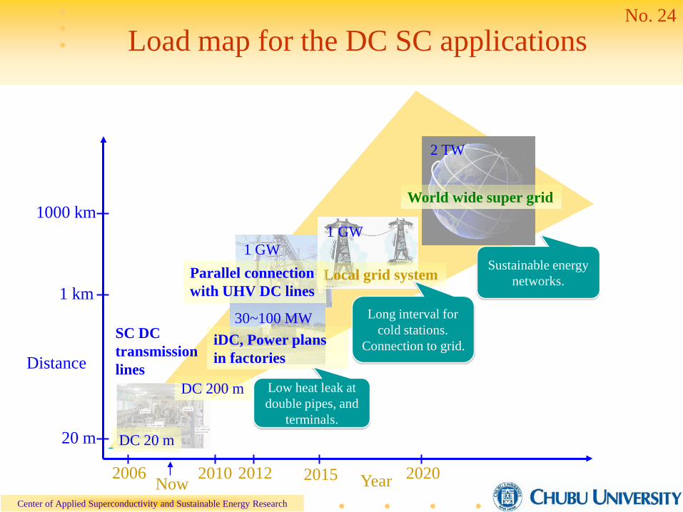
No. 24Load map for the DC SC applications
Distance
Year
DC 20 m
DC 200 m
iDC, Power plans in factories
Local grid system
World wide super grid
1 GW
2 TW
SC DC transmission lines
2010 2012 2015 20202006 Now
1 km
1000 km
20 m
Sustainable energy networks.
Long interval for cold stations.
Connection to grid.
Low heat leak at double pipes, and
terminals.
30~100 MW
1 GWParallel connection with UHV DC lines

Center of Applied Superconductivity and Sustainable Energy Research
Applied Superconducting group in Chubu University
Chancellor and Prof. A. Iiyoshi (Chancellor)Director and Prof. S. Yamaguchi (CASER) Prof. M. Takahashi (Business Administration and Information Science)Prof. A. Hattori (The Chubu Institute for Advanced Studies) Prof. M. Hamabe, Prof. H. Watanabe (CASER)Post Doctor: Dr. T. Sugimoto, Dr. J. Sun, Dr. Y. V. Ivanov