sun blade 6000 modular system site planning guide - oracle
TRANSCRIPT
Sun Blade 6000 Modular System
Site Planning Guide
Part No. E20776-02February 2012

Copyright © 2008, 2012, Oracle and/or its affiliates. All rights reserved.This software and related documentation are provided under a license agreement containing restrictions on use and disclosure and are protected byintellectual property laws. Except as expressly permitted in your license agreement or allowed by law, you may not use, copy, reproduce, translate,broadcast, modify, license, transmit, distribute, exhibit, perform, publish, or display any part, in any form, or by any means. Reverse engineering,disassembly, or decompilation of this software, unless required by law for interoperability, is prohibited.The information contained herein is subject to change without notice and is not warranted to be error-free. If you find any errors, please report them to usin writing.If this is software or related software documentation that is delivered to the U.S. Government or anyone licensing it on behalf of the U.S. Government, thefollowing notice is applicable:U.S. GOVERNMENT RIGHTS Programs, software, databases, and related documentation and technical data delivered to U.S. Government customers are"commercial computer software" or "commercial technical data" pursuant to the applicable Federal Acquisition Regulation and agency-specificsupplemental regulations. As such, the use, duplication, disclosure, modification, and adaptation shall be subject to the restrictions and license terms setforth in the applicable Government contract, and, to the extent applicable by the terms of the Government contract, the additional rights set forth in FAR52.227-19, Commercial Computer Software License (December 2007). Oracle America, Inc., 500 Oracle Parkway, Redwood City, CA 94065.This software or hardware is developed for general use in a variety of information management applications. It is not developed or intended for use in anyinherently dangerous applications, including applications which may create a risk of personal injury. If you use this software or hardware in dangerousapplications, then you shall be responsible to take all appropriate fail-safe, backup, redundancy, and other measures to ensure its safe use. OracleCorporation and its affiliates disclaim any liability for any damages caused by use of this software or hardware in dangerous applications.Oracle and Java are registered trademarks of Oracle and/or its affiliates. Other names may be trademarks of their respective owners.AMD, Opteron, the AMD logo, and the AMD Opteron logo are trademarks or registered trademarks of Advanced Micro Devices. Intel and Intel Xeon aretrademarks or registered trademarks of Intel Corporation. All SPARC trademarks are used under license and are trademarks or registered trademarks ofSPARC International, Inc. UNIX is a registered trademark licensed through X/Open Company, Ltd.This software or hardware and documentation may provide access to or information on content, products, and services from third parties. OracleCorporation and its affiliates are not responsible for and expressly disclaim all warranties of any kind with respect to third-party content, products, andservices. Oracle Corporation and its affiliates will not be responsible for any loss, costs, or damages incurred due to your access to or use of third-partycontent, products, or services.
Copyright © 2008, 2012, Oracle et/ou ses affiliés. Tous droits réservés.Ce logiciel et la documentation qui l’accompagne sont protégés par les lois sur la propriété intellectuelle. Ils sont concédés sous licence et soumis à desrestrictions d’utilisation et de divulgation. Sauf disposition de votre contrat de licence ou de la loi, vous ne pouvez pas copier, reproduire, traduire,diffuser, modifier, breveter, transmettre, distribuer, exposer, exécuter, publier ou afficher le logiciel, même partiellement, sous quelque forme et parquelque procédé que ce soit. Par ailleurs, il est interdit de procéder à toute ingénierie inverse du logiciel, de le désassembler ou de le décompiler, excepté àdes fins d’interopérabilité avec des logiciels tiers ou tel que prescrit par la loi.Les informations fournies dans ce document sont susceptibles de modification sans préavis. Par ailleurs, Oracle Corporation ne garantit pas qu’ellessoient exemptes d’erreurs et vous invite, le cas échéant, à lui en faire part par écrit.Si ce logiciel, ou la documentation qui l’accompagne, est concédé sous licence au Gouvernement des Etats-Unis, ou à toute entité qui délivre la licence dece logiciel ou l’utilise pour le compte du Gouvernement des Etats-Unis, la notice suivante s’applique :U.S. GOVERNMENT RIGHTS. Programs, software, databases, and related documentation and technical data delivered to U.S. Government customersare "commercial computer software" or "commercial technical data" pursuant to the applicable Federal Acquisition Regulation and agency-specificsupplemental regulations. As such, the use, duplication, disclosure, modification, and adaptation shall be subject to the restrictions and license terms setforth in the applicable Government contract, and, to the extent applicable by the terms of the Government contract, the additional rights set forth in FAR52.227-19, Commercial Computer Software License (December 2007). Oracle America, Inc., 500 Oracle Parkway, Redwood City, CA 94065.Ce logiciel ou matériel a été développé pour un usage général dans le cadre d’applications de gestion des informations. Ce logiciel ou matériel n’est pasconçu ni n’est destiné à être utilisé dans des applications à risque, notamment dans des applications pouvant causer des dommages corporels. Si vousutilisez ce logiciel ou matériel dans le cadre d’applications dangereuses, il est de votre responsabilité de prendre toutes les mesures de secours, desauvegarde, de redondance et autres mesures nécessaires à son utilisation dans des conditions optimales de sécurité. Oracle Corporation et ses affiliésdéclinent toute responsabilité quant aux dommages causés par l’utilisation de ce logiciel ou matériel pour ce type d’applications.Oracle et Java sont des marques déposées d’Oracle Corporation et/ou de ses affiliés.Tout autre nom mentionné peut correspondre à des marquesappartenant à d’autres propriétaires qu’Oracle.AMD, Opteron, le logo AMD et le logo AMD Opteron sont des marques ou des marques déposées d’Advanced Micro Devices. Intel et Intel Xeon sont desmarques ou des marques déposées d’Intel Corporation. Toutes les marques SPARC sont utilisées sous licence et sont des marques ou des marquesdéposées de SPARC International, Inc. UNIX est une marque déposée concédée sous licence par X/Open Company, Ltd.Ce logiciel ou matériel et la documentation qui l’accompagne peuvent fournir des informations ou des liens donnant accès à des contenus, des produits etdes services émanant de tiers. Oracle Corporation et ses affiliés déclinent toute responsabilité ou garantie expresse quant aux contenus, produits ouservices émanant de tiers. En aucun cas, Oracle Corporation et ses affiliés ne sauraient être tenus pour responsables des pertes subies, des coûtsoccasionnés ou des dommages causés par l’accès à des contenus, produits ou services tiers, ou à leur utilisation.
PleaseRecycle

Contents
Using This Documentation v
▼ Downloading Chassis Firmware v
Introduction to Site Planning 1
Customer Obligations 1
System Configuration 1
Site Planning Checklist 2
Preparing the Site for System Installation 5
Load-Bearing and Handling Precautions 5
Power and Electrical Requirements 6
Power Consumption 6
Power Budgeting 6
Electrical Requirements 7
Power Cords 7
Grid Redundancy 8
Cooling Requirements 8
Temperature and Humidity Requirements 9
Airflow Requirements 10
Clearance for Service and Aisle Requirements 10
Route to the Data Center 11
Rackmounting Considerations 13
iii

Mounting the Chassis in a Rack 13
Compatible Cabinets 13
Number of Chassis Supported in a Rack 14
Facility Safety 15
Secure Installation Requirements 15
Placement of Product 15
Hazardous Conditions Precaution 16
Specifications 17
Shipping Crate Physical Specifications 17
Chassis and Components Dimensions and Weights 18
AC Power Requirements 19
Environmental Specifications 19
Thermal Design Specifications 20
Acoustic Noise Emissions 20
Regulatory Compliance 21
Glossary 23
Index 25
iv Site Planning Guide for Sun Blade 6000 and Sun Blade 6048 Modular Systems • February 2012

Using This Documentation
This guide provides information on preparing the site for system installation.
This guide is written for system installers and administrators who are familiar withrackmounting systems and installing computer hardware.
The following topics are covered:
■ “Downloading Chassis Firmware” on page v
■ “Documentation and Feedback” on page vi
■ “About This Documentation” on page vi
▼ Downloading Chassis Firmware1. Navigate to the Sun Blade 6000 modular system product page at:
http://www.oracle.com/technetwork/systems/patches/firmware/release-history-jsp-138416.html
2. Click Sun Blade 6000 Chassis.
3. Click the software update version that you want to download.
The Oracle support login page appears.
4. Enter a user name and password.
5. Click the patch name that is displayed.
6. On the main patch page, click Download.
7. Click on the file that is displayed to download.
v

Documentation and Feedback
Provide feedback on this documentation at:http://www.oracle.com/goto/docfeedback
About This DocumentationThis documentation set is available in both PDF and HTML. The information ispresented in topic-based format (similar to online help) and therefore does notinclude chapters, appendices, or section numbering.
A PDF that includes all information on a particular topic subject (such as hardwareinstallation or product notes) can be generated by clicking on the PDF button in theupper left corner of the page.
TABLE P-1
Documentation Link
All OracleProducts
http://www.oracle.com/documentation
Sun Blade 6000modular system
http://download.oracle.com/docs/cd/E19938-01/index.html
Oracle ILOM http://www.oracle.com/technetwork/documentation/sys-mgmt-networking-190072.html
vi Site Planning Guide for Sun Blade 6000 and Sun Blade 6048 Modular Systems • February 2012
Introduction to Site Planning
This document provides system specifications and site requirements you must meetwhen planning to install the Sun Blade 6000 modular system in your data center.
For safety and compliance information, refer to the Safety and Compliance Manual forSun Blade 6000 and Sun Blade 6048 Modular Systems and Important Safety Information forSun Hardware Systems.
These topics provide introductory information on site planning:
■ “Customer Obligations” on page 1
■ “System Configuration” on page 1
■ “Site Planning Checklist” on page 2
Customer ObligationsThe customer is obliged to inform Oracle, Inc. of any and all ordinances andregulations that affect the installation. The customer is responsible for meeting alllocal, national, and international government codes and regulations concerningfacilities, such as safety, building, and electrical codes.
System ConfigurationThe modular configuration of the Sun Blade 6000 modular system consists of thefollowing hardware components:
■ 10U chassis (Sun Blade 6000 chassis)
■ Up to 10 Sun Blade server or storage modules.
■ 1 CMM
■ Up to 2 (NEMs)
1

■ Up to 20 PCIe EMs
■ 2 power supply modules
■ 6 rear fan modules
Site Planning ChecklistThe following table organizes the site planning tasks into a checklist that you can useduring the site planning process.
Requirement Task Completed
Configuration Have you determined the hardware configuration for each system? Yes__ No__
Have you determined the type and number of cabinets and racks youneed?
Yes__ No__
Have you determined how you will populate each rack? Yes__ No__
Have you determined which external peripherals, such as terminals,monitors, keyboards, SCSI devices, and so forth, the systems require?
Yes__ No__
Environmental Does the data center environment meet the system specifications fortemperature and humidity?
Yes__ No__
Have you determined the thermal load, heat dissipation, and airconditioning requirements of all equipment in the data center?
Yes__ No__
2 Site Planning Guide for Sun Blade 6000 and Sun Blade 6048 Modular Systems • February 2012

Can you maintain the data center environment when certain failuresoccur, such as power failure, air conditioning unit failure, or humiditycontrol unit failure?
Yes__ No__
Is fire suppression and alarm equipment installed? Yes__ No__
Power Have you determined the maximum power requirements of the systems? Yes__ No__
Are you using two AC power sources to establish power gridredundancy?
Yes__ No__
Have you installed a modular power system, if required? Yes__ No__
Do you have sufficient power receptacles and circuit breakers for eachsystem and its peripherals?
Yes__ No__
Are the power receptacles within 13 feet (4 m) of the racks? Yes__ No__
Have you installed and labeled the circuit breakers? Yes__ No__
Physical Does the facility’s loading dock meet standard common carrier truckrequirements? If not, have you made other arrangements for unloadingthe racks and systems, such as providing a fork lift?
Yes__ No__
Are pallet jacks or carts available to move the systems and racks from theloading dock to the computer room?
Yes__ No__
Will the equipment fit through the access route and into the computerroom?
Yes__ No__
Have you calculated the weight of each rack with all the equipmentinstalled within it?
Yes__ No__
Is the data center floor able to support the weight of the systems andracks?
Yes__ No__
Have you established where you will locate each rack on the data centerfloor?
Yes__ No__
Are the systems and racks positioned so that the heated exhaust air ofone system does not enter the air inlet of another system?
Yes__ No__
Is there sufficient clearance around the racks for system access andmaintenance?
Yes__ No__
Miscellaneous Are there sufficient people available to unload, unpack, and install thesystems into the racks?
Yes__ No__
Have system administrators and service technicians enrolled inappropriate training courses to upgrade their skills, as necessary?
Yes__ No__
Have you acquired all the hardware needed to set up the systems andracks?
Yes__ No__
Do you have the documents required to install the systems into theracks?
Yes__ No__
Requirement Task Completed
Introduction to Site Planning 3

4 Site Planning Guide for Sun Blade 6000 and Sun Blade 6048 Modular Systems • February 2012

Preparing the Site for SystemInstallation
Install the Sun Blade 6000 modular system in accordance with the local safety codesand regulations at the facility site. You must be familiar with and adhere to the safetyprecautions in the Sun Blade 6000 Modular System Safety and Compliance Manual.
Do not make mechanical or electrical modifications to the equipment. Oracle, Inc. isnot responsible for regulatory compliance of a modified Oracle product.
These topics provide information that you need to prepare your site for systeminstallation:
■ “Load-Bearing and Handling Precautions” on page 5
■ “Power and Electrical Requirements” on page 6
■ “Cooling Requirements” on page 8
■ “Temperature and Humidity Requirements” on page 9
■ “Airflow Requirements” on page 10
■ “Clearance for Service and Aisle Requirements” on page 10
■ “Route to the Data Center” on page 11
Load-Bearing and Handling PrecautionsA fully configured Sun Blade 6000 modular system can weigh in excess of 400pounds (182 kg) while in its shipping container, and 350 pounds (160 kg) whenunpacked. Any floor that this system will cross, or surface on which the system isplaced, must be able to support these loads.
The system is shipped on a pallet. You must maintain the system in a vertical,upright position while it is in its shipping container. Be sure you use enoughpersonnel when moving the system, especially on sloping loading docks and ramps,
5

to gain access to a raised computer room floor. Move the system slowly anddeliberately, and ensure that the floor is free of foreign objects, cables, or otherobstructions.
Power and Electrical RequirementsThe Sun Blade 6000 modular system uses two 200–240V, 5600W power supplymodules. The following topics describe the power and electrical requirement for thechassis:
■ “Power Consumption” on page 6
■ “Power Budgeting” on page 6
■ “Electrical Requirements” on page 7
■ “Power Cords” on page 7
■ “Grid Redundancy” on page 8
Power ConsumptionThe amount of power that the system consumes dependents on its configuration, thatis, the number of active modular components installed. To determine the powerredundancy requirements, you need to know:
■ Source power available
■ Power consumption (depends on component configuration)
■ Redundancy level required
The system requires a minimum of four AC inputs. To provide 2N powerredundancy at a 5600W consumption level, and to ensure that the system can toleratea loss of one power supply, the system should never exceed 6250W of powerconsumption at any given time.
Power BudgetingThe power requirements for different components in the Sun Blade 6000 system areprovided through the power conversion calculator. Use the power calculator forestimating the power consumption of your system:
http://www.oracle.com/us/products/servers-storage/sun-power-calculators/calc/6000chassis-power-calculator.html
6 Site Planning Guide for Sun Blade 6000 and Sun Blade 6048 Modular Systems • February 2012

The intent of the power calculator is to provide guidance for estimating the electricaland heat loads for typical operating conditions. The Max power results shown in thecalculator (at 100% workload) represent server module power consumptionmeasurements with CPUs at 100% utilization running SPECjbb2005. The Idle powerresults shown in the calculator represent power consumption measurements takenfrom server modules with operating systems booted and stabilized, yet running atminimal utilization.
Results shown are representative of measurements taken with room temperaturesbelow 25o C. Actual power consumption will vary with application type, applicationutilization and ambient temperature. Whenever possible, use actual measurements.
Use these specifications for planning purposes only. The system’s actual powerrequirements depend on which components are included in your configuration. UseOracle ILOM to verify the system’s actual power requirements. Refer to the OracleILOM documentation.
Oracle ILOM documentation is available at:http://www.oracle.com/pls/topic/lookup?ctx=ilom30&id=homepage
Electrical RequirementsThe data center must meet the following electrical requirements for installation of aSun Blade 6000 system:
■ Four 200–240 VAC, 16A/20A branch circuits, one for each of the AC inlets on thesystem, are required.
Each AC inlet requires a separate power cord; therefore, four power cords arerequired. The power cord must be rated at 16A or 20A, depending on the sitelocation.
■ If you are using an Oracle MPS in the cabinet, refer to the documentation suppliedwith the cabinet for the MPS power requirements.
■ If you are not using an MPS, you must supply a branch circuit with a connectorthat meets the requirements of your system.
Power CordsThe connection to the Sun Blade 6000 chassis AC inlet requires the following types ofpower cords, dependent on site location and power source.
■ If you are connecting the system directly to an external power source (for example,power is not obtained through a modular power system), use the power cordsdescribed in the following table.
Preparing the Site for System Installation 7
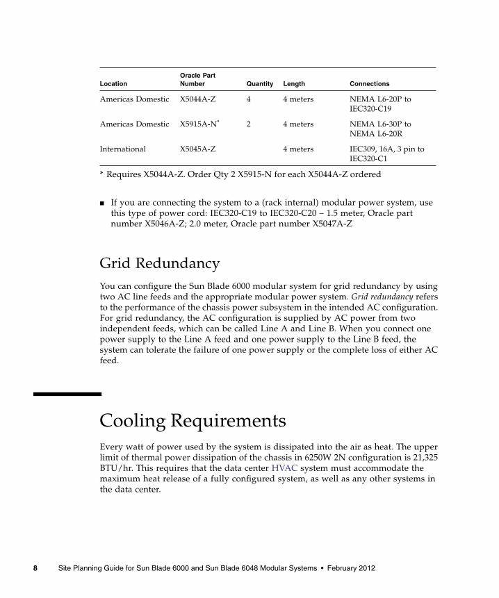
■ If you are connecting the system to a (rack internal) modular power system, usethis type of power cord: IEC320-C19 to IEC320-C20 – 1.5 meter, Oracle partnumber X5046A-Z; 2.0 meter, Oracle part number X5047A-Z
Grid RedundancyYou can configure the Sun Blade 6000 modular system for grid redundancy by usingtwo AC line feeds and the appropriate modular power system. Grid redundancy refersto the performance of the chassis power subsystem in the intended AC configuration.For grid redundancy, the AC configuration is supplied by AC power from twoindependent feeds, which can be called Line A and Line B. When you connect onepower supply to the Line A feed and one power supply to the Line B feed, thesystem can tolerate the failure of one power supply or the complete loss of either ACfeed.
Cooling RequirementsEvery watt of power used by the system is dissipated into the air as heat. The upperlimit of thermal power dissipation of the chassis in 6250W 2N configuration is 21,325BTU/hr. This requires that the data center HVAC system must accommodate themaximum heat release of a fully configured system, as well as any other systems inthe data center.
LocationOracle PartNumber Quantity Length Connections
Americas Domestic X5044A-Z 4 4 meters NEMA L6-20P toIEC320-C19
Americas Domestic X5915A-N*
* Requires X5044A-Z. Order Qty 2 X5915-N for each X5044A-Z ordered
2 4 meters NEMA L6-30P toNEMA L6-20R
International X5045A-Z 4 meters IEC309, 16A, 3 pin toIEC320-C1
8 Site Planning Guide for Sun Blade 6000 and Sun Blade 6048 Modular Systems • February 2012

The amount of heat output per Sun Blade 6000 system varies, depending on thesystem configuration. The systems are equipped with fans that route cool airthroughout the chassis from front to rear. The fans are speed controlled based onsystem temperature sensors. Typical airflow (for room temperatures below 23o C) isabout 600 CFM. Maximum possible airflow is about 1012 CFM.
As long as the necessary air conditioning is provided in the data center to dissipatethe heat load, and sufficient space and properly vented door openings are providedat the front and back of rackmounted systems (see “Clearance for Service and AisleRequirements” on page 10), the system fans will enable the system to work withinthe temperature specifications for systems in operation (see “EnvironmentalSpecifications” on page 19). Thermal characteristics of the Sun Blade 6000 chassissystem are provided in “Thermal Design Specifications” on page 20.
Temperature and HumidityRequirementsThe operating and nonoperating temperature specifications listed in “EnvironmentalSpecifications” on page 19 reflect the system’s hardware limits, in order to meet allfunctional requirements. Note that the operating temperatures apply to the airentering the system and not necessarily the temperature of the air in the aisles.
Avoid temperature and humidity extremes. The optimum operating ambienttemperature and humidity ranges are the recommended operating environment.Operating the system within the ambient temperature range is optimal for systemreliability. At 23o C (73.4o F) it is easy to maintain safe relative humidity ranges andto provide a buffer if the environmental support system fails.
Ambient relative humidity levels between 45 percent and 50 percent are the mostsuitable for system operations to:
■ Prevent corrosion.
■ Provide an operating time buffer in the event of an environmental control systemfailure.
■ Help avoid failures due to intermittent interference from static discharges that canoccur when relative humidity is too low. ESD is easily generated and less easilydissipated in areas where the relative humidity is below 35 percent, and becomescritical when levels drop below 30 percent.
Conditions should not be allowed to fluctuate by more than 5.5 o C (10 oF) or 10percent relative humidity during a 60-minute period.
Preparing the Site for System Installation 9

Airflow RequirementsThe system uses forced air to draw in ambient air for cooling from the front of thechassis, while heated air exits the rear of the chassis. The design of the systemprovides two primary regions of airflow: The lower airstream cools the servermodules, and the upper airstream cools the power supplies, chassis monitoringmodules, Sun Blade 6000 network express modules, and PCIe ExpressModules.
The rear fan cage includes six rear fan modules, each module having two fans, for atotal of 12 fans. The fans draw cool air through the front of the server modules andexhaust heated air through the back of the chassis. This results in a typicalmeasurement of approximately 600 CFM of total airflow.
The upper airstream provides forced air by using a combination of internal fanswithin each power supply.
Follow these airflow guidelines:
■ Do not block the ventilation areas of the chassis.
■ Ensure that all cabling at the rear of the chassis does not block any exhaust air.
■ Ensure that front and rear cabinet doors are at least 60 percent perforated toensure minimal restriction of airflow. Removal of either or both doors willimprove the cooling capability of the system.
■ Front and rear clearance between the inside of the cabinet doors and the systemshould allow a minimum of 0.2 inch (0.5 cm) at the front of the system and 3.1inches (7.9 cm) at the rear of the system for proper airflow.
Clearance for Service and AisleRequirementsTo enable installation and servicing of the system, including access to system cables,follow these space restrictions.
Location Service Access Requirement
System extended from rack 3 feet (0.9 m) on both sides of the system to facilitateinstallation
Front cold aisle 5 feet (1.5 m); required for rackmounting
10 Site Planning Guide for Sun Blade 6000 and Sun Blade 6048 Modular Systems • February 2012

Arrange racks in a hot aisle–cold aisle layout. This layout enables cool air to flowthrough the aisles to the system’s front air intake and enables heated air to flow fromthe system’s back exhaust. A hot aisle–cold aisle layout eliminates the direct transferof hot exhaust air from one system into the intake air of another system.
Route to the Data CenterIdeally, the data center and loading dock should be located in close proximity to oneanother. The access allowances for the path from the loading dock to the data centermust include:
■ A minimum 56-inch (142-cm) height
■ A minimum 37-inch (94-cm) width (greater is recommended)
The system chassis and factory-installed components ship in a single container on apallet. The system must be kept in a vertical, upright position at all times while in itsshipping container. Ensure that the equipment and personnel unloading the chassisshipping container can handle the shipping dimensions and weight of the container.See “Shipping Crate Physical Specifications” on page 17 for shipping container andweight specifications.
If there is a significant temperature or humidity difference between the system andthe data center environment, keep the system in its shipping container in a locationthat has a temperature and humidity environment similar to that of the data center.Wait at least 24 hours before removing the system from its shipping container toprevent thermal shock and condensation.
Provide a room that is separate from the data center in which to open equipmentcartons and to repack hardware when you install and remove parts. Avoid unpackingthe cartons in the data center. Dirt and dust from the packing materials cancontaminate the data center.
Back hot aisle 3 feet (0.9 m); required for cable access
Location Service Access Requirement
Preparing the Site for System Installation 11

12 Site Planning Guide for Sun Blade 6000 and Sun Blade 6048 Modular Systems • February 2012

Rackmounting Considerations
This section describes information that you need to consider when planning torackmount the systems.
These topics are covered in this section:
■ “Mounting the Chassis in a Rack” on page 13
■ “Compatible Cabinets” on page 13
■ “Number of Chassis Supported in a Rack” on page 14
Mounting the Chassis in a RackYou should use a mechanical lift to install the chassis into the rack. To install thechassis manually, you will need four people. Refer to the Sun Blade 6000 RackAlignment Template, for specific instructions on rackmounting the chassis. Thisdocument is available at:http://www.oracle.com/pls/topic/lookup?ctx=sb6000&id=homepage
Compatible CabinetsThe chassis is designed for rackmounting. It can be mounted into 19-inch EIA-310Dcabinets with a depth of 35.4 to 39.4 inches (90.0 to 100.1 cm). The chassis canaccommodate corresponding front-to-back, rail-to-rail spacing of 26.77 inches(68.0 cm) to 34.25 inches (87.0 cm).
Oracle offers EIA 310D-compliant cabinets for mounting the Sun Blade 6000 modularsystem. The Sun Rack 1000 cabinet family is among the newer cabinets from Oracle.These cabinets are designed to hold three Sun Blade 6000 modular system (Sun Rack1000-38) or four Sun Blade 6000 modular systems (Sun Rack 1000-42). The followingtable lists the physical specifications for the Sun Rack 1000 cabinets.
13

Number of Chassis Supported in a RackUp to four Sun Blade 6000 chassis can be installed in a 1000-42 rack, with theexceptions shown in the following list.
The following configurations are supported by MPS:
■ Worst case consumption (32A), 60A-3 phase: one Sun Blade 6000 chassis
■ One 32A-3 phase – three Sun Blade 6000 chassis
■ Two 60A-3 phase – three Sun Blade 6000 chassis
■ Two 30A-1 phase – one Sun Blade 6000 chassis
Specification Sun Rack 1000-38 Sun Rack 1000-42
Usable rack units 38 42
Height 74 inches (188 cm) 81 inches (205.7 cm)
Width 23.5 inches (60 cm) 23.5 inches (60 cm)
Depth 39.4 inches(1000 cm)
39.4 inches(1000 cm)
Weight of empty rack 370 lb (167.8 kg) 426 lb (193.2 kg)
Weight of empty rack with shipping pallet 540 lb (244.9 kg) 683 lb (309.7 kg)
Weight of empty rack with MPS (no pallet) 465 lb (210.9 kg) 521 lb (236.3 kg)
Load capacity 1200 lb (544 kg) 1200 lb (544 kg)
14 Site Planning Guide for Sun Blade 6000 and Sun Blade 6048 Modular Systems • February 2012

Facility Safety
Observe the following guidelines and precautions when installing the Sun Blade 6000modular system.
■ “Secure Installation Requirements” on page 15
■ “Placement of Product” on page 15
■ “Hazardous Conditions Precaution” on page 16
Secure Installation RequirementsTo minimize personal injury in the event of a seismic occurrence, you must securelyfasten the cabinet in which the system is rackmounted to a rigid structure extendingfrom the floor to the ceiling, or from the walls, of the room in which the cabinet islocated.
Install a stand-alone system or a rackmounted system on a level surface. At the baseof the cabinet is an anti-tilt bar. This bar must be extended before you install the SunBlade 6000 modular system to prevent the cabinet from moving.
Placement of ProductDo not block or cover the openings of the Sun Blade 6000 modular system. Neverplace an Oracle product near a radiator or heat register.
Failure to follow these guidelines can cause overheating and affect the reliability ofyour Oracle product. Air cools the Sun Blade 6000 modular system from front toback. The front and rear cabinet door clearances must provide sufficient space forcooling. See “Airflow Requirements” on page 10 for specific clearance specifications.
15

Hazardous Conditions PrecautionBecause of the inherent nature of the system’s modular design, take care to ensurethat operators are not exposed to moving parts and sharp edges.
16 Site Planning Guide for Sun Blade 6000 and Sun Blade 6048 Modular Systems • February 2012

Specifications
This following topics describe the system specifications.
■ “Shipping Crate Physical Specifications” on page 17
■ “Chassis and Components Dimensions and Weights” on page 18
■ “AC Power Requirements” on page 19
■ “Environmental Specifications” on page 19
■ “Thermal Design Specifications” on page 20
■ “Acoustic Noise Emissions” on page 20
■ “Regulatory Compliance” on page 21
Shipping Crate Physical SpecificationsThe standard Sun Blade 6000 modular system is shipped with the followingcomponents installed:
■ 1 Sun Blade 6000 chassis
■ 2 power supply modules
■ 6 rear fan modules
■ 2 front fan modules
■ 1 CMM
■ 9 server module filler panels, 20 PCIe EM filler panels, and 2 NEM filler panels
Also shipped with the Sun Blade 6000 modular system are:
■ Rackmount rail kit (including shipping brackets)
■ Rack alignment template
■ DB-9 to RJ-45 adapter
■ Dongle (multi-port cable)
■ Documentation
17

The chassis shipping crate physical specifications are shown in the following table.
Chassis and Components Dimensionsand WeightsThe unpacked chassis and component dimensions and weights are shown in thefollowing table.
Dimension or Weight Specification
Shipping crate height 50.9 inches (129.3 cm)
Shipping crate width 26.5 inches (67.3 cm)
Shipping crate length 36 inches (91.4 cm)
Chassis, packaging, and pallet weight Approximately 600 lb (272 kg)
Dimension or Weight Specification
Chassis height 17.25 inches (438.15 mm); (10 rack units without clearance)
Chassis depth 27.25 inches (692.15 mm); includes chassis metal and front bezel
Chassis width 17.50 inches (444.5 mm); does not include rackmounting ears
Chassis weight Fully configured system: 350 lb (159 kg)Empty chassis: 78.7 lb (35.7 kg)
Subassemblyweights
• I/O chassis with midplane: 26 lb (11.79 kg)• Power supply module: 21.38 lb (9.7 kg)• Front fan module: 1.95 lb (0.88 kg)• Rear fan module: 2.31 lb (1.04 kg)• Network express module: 3.85 lb (1.75 kg)• PCIe ExpressModule: 0.90 lb (0.41 kg)• Chassis monitoring module: 1.15 lb (0.52 kg)• Front indicator module: 0.75 lb (0.34 kg)• Server module - see server module documentation
18 Site Planning Guide for Sun Blade 6000 and Sun Blade 6048 Modular Systems • February 2012

AC Power RequirementsThe AC power requirements of the system are shown in the following table.
Environmental SpecificationsThe environmental specifications of the system are shown in the following table.
Power Type Function Specification
AC Power Input power 1+1 PSU rating, 6272 W or 6400 VA each powersupply module
Voltage 200 to 240 VAC
Frequency 50 to 60 Hz
Current 16A per output, total four AC inputs (two perpower supply module).
Number of AC inputs 4
AC input connection • Americas Domestic – NEMA L6-20P toIEC320-C19M(4m, Oracle PN X5044A-Z)
• International – IEC309, 250 V, 16 A, 3 Pin toIEC320-C19 (4m, Oracle PN X5045A-Z)
• Installed in rack with modular power system –IEC320-C319 to IEC320-C20 (1.5m, Oracle PNX5046A-Z; (2.0m, X5047A-Z)
DC Power Output power 1+1 PSU rating, 5740 W each power supplymodule
Specification Operating Nonoperating
Temperature 5 to 32o C (41 to 90 oF)noncondensing
–40 to 65o C(–40 to 149o F)noncondensing
Optimum ambient temperature 22o C (71.6o F)
Specifications 19

Thermal Design SpecificationsThe thermal design specifications of the system are shown in the following table.
Acoustic Noise EmissionsDeclared noise emissions are in accordance with ISO 9295/9296 standards.
Data center personnel should take necessary precautions to reduce exposure to thehigh noise levels. Acoustic noise emission levels are shown in the following table.
Relative humidity (RH) 10 to 90% RH,noncondensing,27o C max wet bulb
5 to 93% RH,noncondensing,38o C max wet bulb
Optimum ambient relativehumidity
45 to 50% RH,noncondensing
Altitude 0 to 10,000 feet (3048 m)maximum ambienttemperature is derated by1o C per 300 m (984 ft)above 900 m (2953 ft)
0 to 39,370 feet(12,000 m)
Sine vibration Operating: Z (vertical)axis: 0.15 G, X-Y axis: 0.10G, 5 Hz-500 Hz sine
Z (vertical) axis: 0.50 G,X-Y axis: 0.25 G, 5Hz-500 Hz sine
Shock 3 Gs, 11 msec, half sine(rackmounted enclosure)
Parameter Specification
Maximum possible system volumetric airflow 1012 CFM
Maximum possible heat dissipation/HVAC load 21,325 BTU/hr
Maximum possible temperature rise through chassis 18.5o C (33o F)
Specification Operating Nonoperating
20 Site Planning Guide for Sun Blade 6000 and Sun Blade 6048 Modular Systems • February 2012

Regulatory ComplianceThe system complies with the Oracle and regulatory agency standards shown in thefollowing table.
Function Specification
Operating/idling acoustic noise(LwAd, 1B=10 dB)
8.6 B at or below 25o C, 9.2 B at maximum ambient
Category Standard
Product safety • UL approved to UL 60950 and C22.2 No. 60950• UL Demko approval to EN60950-1 and CB Report IEC 60950-1;
including all amendments and full worldwide deviations• GOST Certification for Russia• Korean MIC Certification• China CCC Mark for power supply (system is exempt since it is
rated greater than 1300W)• CE Declaration of Conformity (SMI self-declaration) to The
Electromagnetic Compatibility Directive and Low VoltageDirective 2006/95/EC
• IRAM S-Mark for power supply (system is exempt due to class ofequipment)
• CNS 14336 (Taiwan)
Laser product andoptical I/O
• FCC Registration to Code of Federal regulations 21 CFR1040-Lasers
• TUV approval to IEC 60825-1 Safety of Laser Products• Canadian Radiation Emitting Devices Act REDR C1370
Specifications 21

Electromagneticinterference
• CFR 47 Part 15 (Code of Federal Regulations, Part 15, Subpart B)Class A
• EN55022:2006 Class A per EMC Directive 2004/108/EEC (CEMark)
• VCCI Class A• Industry Canada ICES-003• AS/NZ 3548 (Australia/New Zealand)• CNS 13438 (Taiwan)
Immunity EN55024:1998 +A1:2001 +A2:2003 per EMC Directive2004/108/EEC, including:• IEC 61000-4-2 Electrostatic discharge immunity test• IEC 61000-4-3 Radiated, radio-frequency, electromagnetic field
immunity test• IEC 61000-4-4 Electrical fast transient/burst immunity test• IEC 61000-4-5 Surge immunity test• IEC 61000-4-6 Immunity to conducted disturbances, induced by
radio-frequency fields• IEC61000-4-8 Power frequency magnetic field immunity test• IEC 61000-4-11 Voltage dips, short interruptions, and voltage
variations immunity tests
Line distortion • EN 61000-3-2 per EMC Directive 89/336/EEC
Voltage fluctuationsand flicker
• EN 61000-3-3 per EMC Directive 89/336/EEC
Category Standard
22 Site Planning Guide for Sun Blade 6000 and Sun Blade 6048 Modular Systems • February 2012

Glossary
CCFM Cubic feet per minute
CMM Chassis monitoring module
EESD Electrostatic discharge
HHVAC Heating, ventilation, and air conditioning
MMPS Modular power system
23
NNEM Network Express Module
OOracle ILOM Oracle Integrated Lights Out Manager
PPCIe EM PCIe ExpressModule
24 Site Planning Guide for Sun Blade 6000 and Sun Blade 6048 Modular Systems • February 2012

Index
AAC power requirements, 19acoustic noise emissions, 20airflow requirements for chassis installation, 10
Ccabinets compatible for chassis, 13chassis
configuration, 1specifications, 18
checklist for site planning, 2clearance requirements
for chassis service, 10for site aisle, 10
configuration of system, 1cooling requirements for chassis, 8customer obligations for site planning, 1
Ddata center
preparing a route, 11
Eelectrical requirements for chassis installation, 6environmental specifications, 19
Ffacility safety, 15
Hhandling precautions for chassis installation, 5hazardous conditions precaution, 16humidity requirements for chassis installation, 9
Lload-bearing precautions for chassis installation, 5
Nnumber of chassis supported in rack, 14
Ppower budgeting for chassis, 6power requirements for chassis installation, 6preparing for site planning, 5product placement, 15
Rrackmounting
compatible cabinets, 13number of chassis supported a rack, 14site planning considerations, 13
regulatory compliance, 21route to the data center, 11
Ssafety
hazardous conditions precaution, 16product placement, 15
secure installation requirements, 15shipping crate specifications, 17site planning, 15site planning checklist, 2specifications
AC power requirements, 19acoustic noise emissions, 20chassis, 18components, 18environmental, 19shipping crate, 17thermal design, 20
25

Ttemperature requirements for chassis installation, 9
thermal design specifications, 20
26 Site Planning Guide for Sun Blade 6000 and Sun Blade 6048 Modular Systems • February 2012