summer school quel message voulez-vous diffuser · the betz limit, cp,max (theoretical) ... it is...
TRANSCRIPT

Quel message voulez-vous diffuser ?
SUMMER SCHOOL
• 01/07/2016
Dr. Ing. Dhaker ABBESProfessor-Researcher
Co-responsible of ESEA Field
10/08/2016 1

Renewable Energy SourcesCourse Program
• Context : Economic and environmental challenge
• Problematic : Integration of Renewable Energy
• Objective of course first part (3 hours) :
Bringing necessary knowledge for understanding wind power systems
10/08/2016 2

Overview - Chain of electricity generation
WIND Turbine / TIDAL
PHOTOVOLTAIC
Sunlight solar panels Load / GridPower Converter
Wind or water pressure
Turbine Load/GridPower Converter
Generator
10/08/2016 3
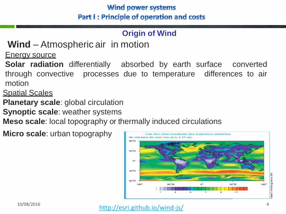
Origin of Wind
Wind – Atmospheric air in motionEnergy source
Solar radiation differentially absorbed by earth surface converted
through convective processes due to temperature differences to air
motion
Spatial Scales
Planetary scale: global circulation
Synoptic scale: weather systems
Meso scale: local topography or thermally induced circulations
Micro scale: urban topography
http://esri.github.io/wind-js/10/08/2016 4
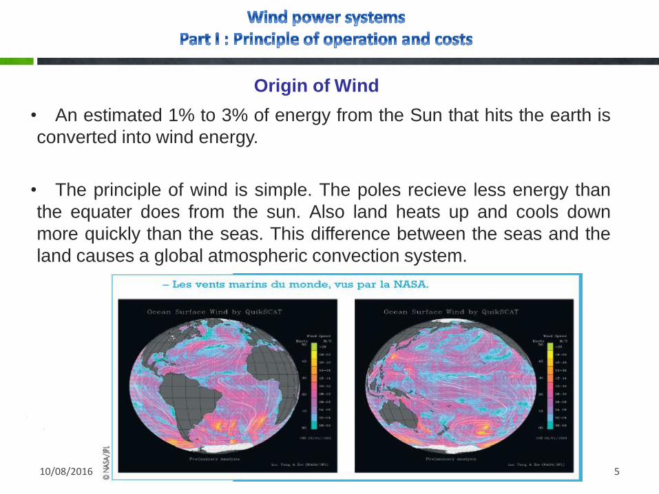
Origin of Wind
10/08/2016 5
• An estimated 1% to 3% of energy from the Sun that hits the earth is
converted into wind energy.
• The principle of wind is simple. The poles recieve less energy than
the equater does from the sun. Also land heats up and cools down
more quickly than the seas. This difference between the seas and the
land causes a global atmospheric convection system.

Growth in global wind installed power
10/08/2016 6

10/08/2016 7
Growth in global wind installed power

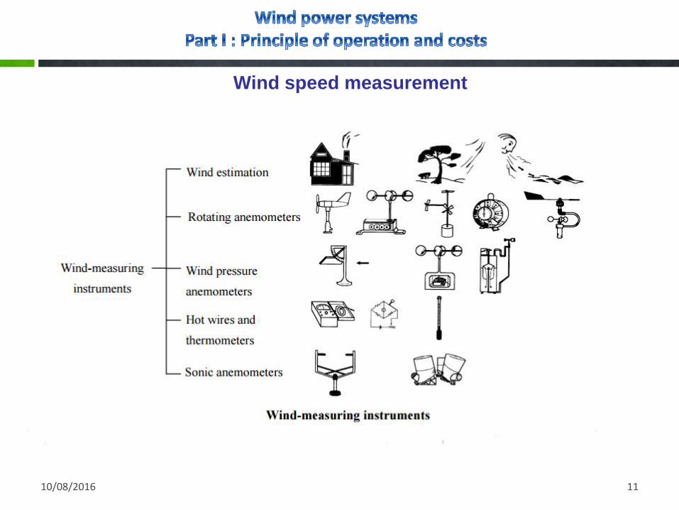
Wind speed measurement
10/08/2016 8
Cup anemometer
Wind speed is normally measured by a cup anemometer consisting of three or four
cups, conical or hemispherical in shape, mounted symmetrically about a vertical
spindle.
Measuring wind direction
Wind direction is measured by a vane consisting of a thin horizontal arm carrying a
vertical flat plate at one end with its edge to the wind and at the other end a balance
weight which also serves as a pointer. The arm is carried on a vertical spindle mounted
on bearings which allow it to turn freely in the wind. The anemometer and wind vane
are each attached to a horizontal supporting arm at the top of a 10 m mast.

10/08/2016 9
Wind speed measurement

10/08/2016 10
Wind speed measurement
Sonic anemometer
Where wind measurements are made in extreme weather conditions, such as on the
top of mountains, a heated sonic anemometer is used (see above image) having no
moving parts. The instrument measures the speed of acoustic signals transmitted
between two transducers located at the end of thin arms. Measurements from two pairs
of transducers can be combined to yield an estimate of wind speed and direction.
The distortion of the air flow by the structure supporting the transducers is a problem
which can be minimized by applying corrections based on calibrations in a wind tunnel.
10/08/2016 11
Wind speed measurement
10/08/2016 12
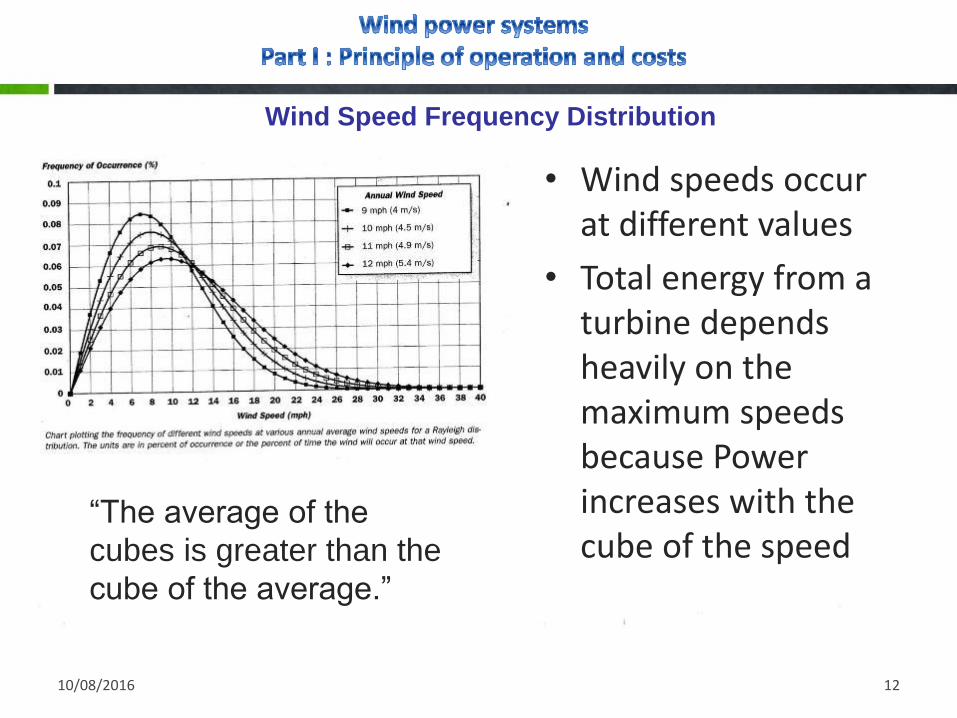
Wind Speed Frequency Distribution
• Wind speeds occur at different values
• Total energy from a turbine depends heavily on the maximum speeds because Power increases with the cube of the speed
“The average of the
cubes is greater than the
cube of the average.”

10/08/2016 13
Wind Energy potential assessment
Energy output estimation for wind turbines has been dealt by a number of researchers and
references. Some authors implement simple methods evaluating a perturbation from mean
wind speed and variance. For example, to calculate the available wind power, Kainkwa
suggests a formula :
As well, Paul Gipe introduced the “swept area‟s method”. It consists of determining the wind
power and then estimating the potential production of energy Ea, simply knowing the area swept
by the rotor A:
With F is the Rayleigh distribution factor and η is the overall efficiency of the wind conversion
system.
10/08/2016 14
Wind Energy potential assessment
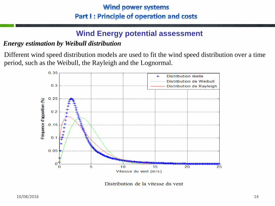
Energy estimation by Weibull distribution
Different wind speed distribution models are used to fit the wind speed distribution over a time
period, such as the Weibull, the Rayleigh and the Lognormal.
10/08/2016 15
Wind Energy potential assessment
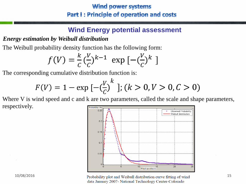
Energy estimation by Weibull distribution
The Weibull probability density function has the following form:
The corresponding cumulative distribution function is:
Where V is wind speed and c and k are two parameters, called the scale and shape parameters,
respectively.

10/08/2016 16
Wind Energy potential assessment
Energy estimation by Weibull distribution
To determine the energy capture of the turbine over a time period T, we can just multiply the
power Pe by f (V) * T so that the energy captured over a time period T (ignoring down time) will
be:
With Vi is the wind cut in speed (4m/s) and Vo is the cut out wind speed (25 m/s ). Unfortunately,
the integral does not have a closed mathematical form in general and so a numerical integration is
required, such as the trapezoidal rule or Simpson‟s rule.
Within one year time period and for 10 data wind points, the energy capture will be, using the
trapezoidal rule,

10/08/2016 17
Wind Energy potential assessment
Energy estimation by Weibull distribution

10/08/2016 18

10/08/2016 19

10/08/2016 20

10/08/2016 21
10/08/2016 22

10/08/2016 23
10/08/2016 24
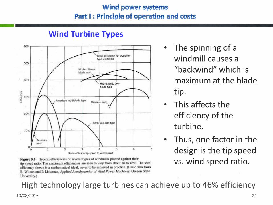
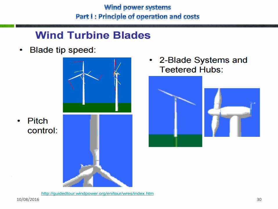
High technology large turbines can achieve up to 46% efficiency
• The spinning of a windmill causes a “backwind” which is maximum at the blade tip.
• This affects the efficiency of the turbine.
• Thus, one factor in the design is the tip speed vs. wind speed ratio.
Wind Turbine Types

10/08/2016 25
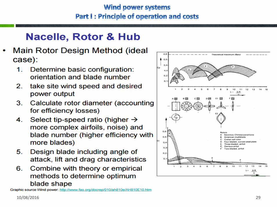
Rotor Designs
• Two blades are cheaper but do not last as long
• Three blades are more stable and last longer
• Options include:
• Upwind vs downwind
• Passive vs active yaw
• Common option chosen is to
direct the rotor upwind of thetower with a tail vane

10/08/2016 26

10/08/2016 27

10/08/2016 28
10/08/2016 29
10/08/2016 30

10/08/2016 31
10/08/2016 32

10/08/2016 33

10/08/2016 34

10/08/2016 35
% Cost Share of 5 MW Turbine Components
10/08/2016 36

10/08/2016 37
Life Cycle Cost of Small wind turbines
10/08/2016 38
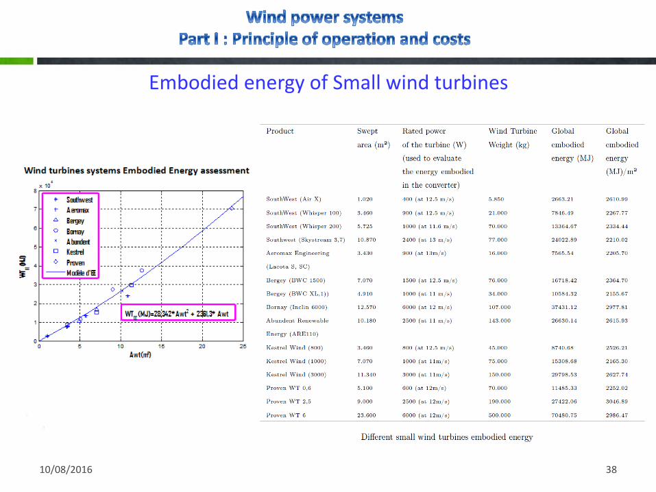
Embodied energy of Small wind turbines

10/08/2016 39

10/08/2016 40
Wind power conversion
The function of a wind turbine is to convert the linear motion of the wind into rotational energy that can be used to drive a generator.
Wind turbines capture the power from the wind by means of aerodynamicallydesigned blades and convert it into rotating mechanical power. At present, themost popular wind turbine is the Horizontal Axis Wind Turbine (HAWTs) where thenumber of blades is typically three.
10/08/2016 41
Wind power conversion
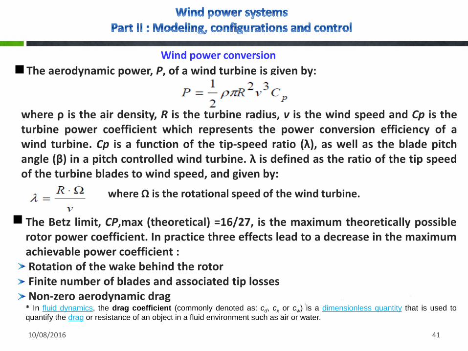
The aerodynamic power, P, of a wind turbine is given by:
where ρ is the air density, R is the turbine radius, v is the wind speed and Cp is theturbine power coefficient which represents the power conversion efficiency of awind turbine. Cp is a function of the tip-speed ratio (λ), as well as the blade pitchangle (β) in a pitch controlled wind turbine. λ is defined as the ratio of the tip speedof the turbine blades to wind speed, and given by:
where Ω is the rotational speed of the wind turbine.
The Betz limit, CP,max (theoretical) =16/27, is the maximum theoretically possiblerotor power coefficient. In practice three effects lead to a decrease in the maximumachievable power coefficient :Rotation of the wake behind the rotorFinite number of blades and associated tip lossesNon-zero aerodynamic drag
* In fluid dynamics, the drag coefficient (commonly denoted as: cd, cx or cw) is a dimensionless quantity that is used to
quantify the drag or resistance of an object in a fluid environment such as air or water.

10/08/2016 42
Wind power conversion
A typical Cp-λ curve for a fixed pitch angle β is shown in Figure. It can be seen thatthere is a practical maximum power coefficient, Cp,max. Normally, a variablespeed wind turbine follows the Cp,max to capture the maximum power up to therated speed by varying the rotor speed to keep the system at the optimum tip-speed ratio, λopt.
Characteristic Cp λ of a wind turbine for a fixed angle β

10/08/2016 43
Fixed speed wind power conversion systemIn a fixed speed wind power conversion system, the power may be limitedaerodynamically either by stall, active stall or by pitch control. Normally inductiongenerators are used in fixed speed systems, which are almost independent oftorque variation and operate at a fixed speed (slip variation of 1-2%).
All three systems are using a soft-starter in order to reduce the inrush currentand there by limit flicker problems on the grid. They also need a reactive powercompensator to reduce (almost eliminate) the reactive power demand from theturbine generators to the grid. It is usually done by continuously switchingcapacitor banks following the production variation (5-25 steps).
Those solutions are attractive due to cost and reliability but they are not able (withina few ms) to control the active power very fast. The generators have typically a pole-shift possibility in order to maximize the energy capture.
10/08/2016 44
Fixed speed wind power conversion systemIn a fixed speed wind power conversion system, the power may be limitedaerodynamically either by stall, active stall or by pitch control. Normally inductiongenerators are used in fixed speed systems, which are almost independent oftorque variation and operate at a fixed speed (slip variation of 1-2%).
All three systems are using a soft-starter in order to reduce the inrush currentand there by limit flicker problems on the grid. They also need a reactive powercompensator to reduce (almost eliminate) the reactive power demand from theturbine generators to the grid. It is usually done by continuously switchingcapacitor banks following the production variation (5-25 steps).
Those solutions are attractive due to cost and reliability but they are not able (withina few ms) to control the active power very fast. The generators have typically a pole-shift possibility in order to maximize the energy capture.
10/08/2016 45
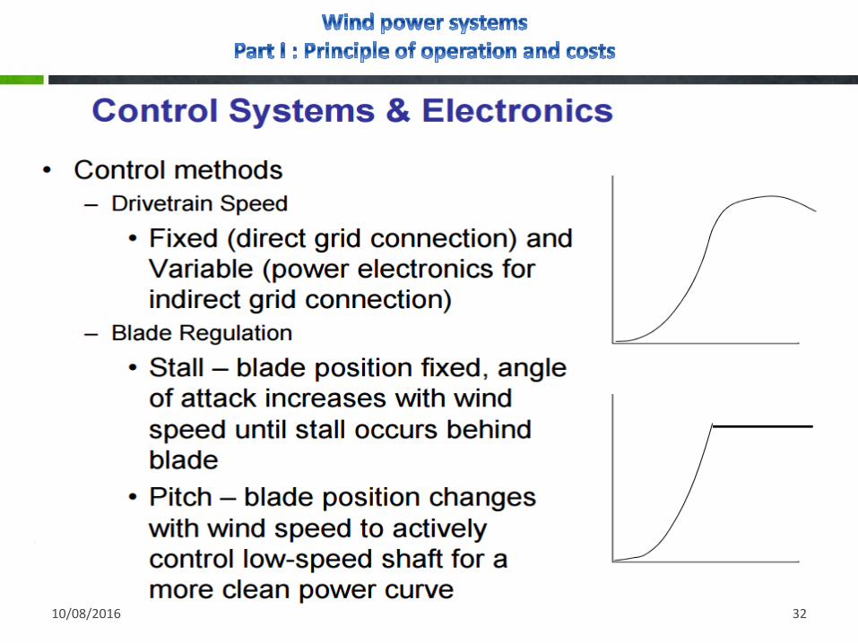
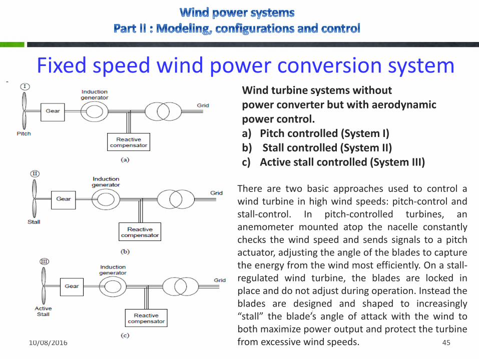
Fixed speed wind power conversion systemWind turbine systems without power converter but with aerodynamic power control.a) Pitch controlled (System I)b) Stall controlled (System II) c) Active stall controlled (System III)
There are two basic approaches used to control awind turbine in high wind speeds: pitch-control andstall-control. In pitch-controlled turbines, ananemometer mounted atop the nacelle constantlychecks the wind speed and sends signals to a pitchactuator, adjusting the angle of the blades to capturethe energy from the wind most efficiently. On a stall-regulated wind turbine, the blades are locked inplace and do not adjust during operation. Instead theblades are designed and shaped to increasingly“stall” the blade’s angle of attack with the wind toboth maximize power output and protect the turbinefrom excessive wind speeds.

10/08/2016 46
Fixed speed wind power conversion system• Benefits
Simple and well known system
Economic
• Disadvantages
Energy losses due to the multiplier
Significant vibrations
Significant noise
Faster wear
Oil maintenance of the multiplier (risk of leaks)
Higher fire risk
The electricity produced is of lower quality
10/08/2016 47
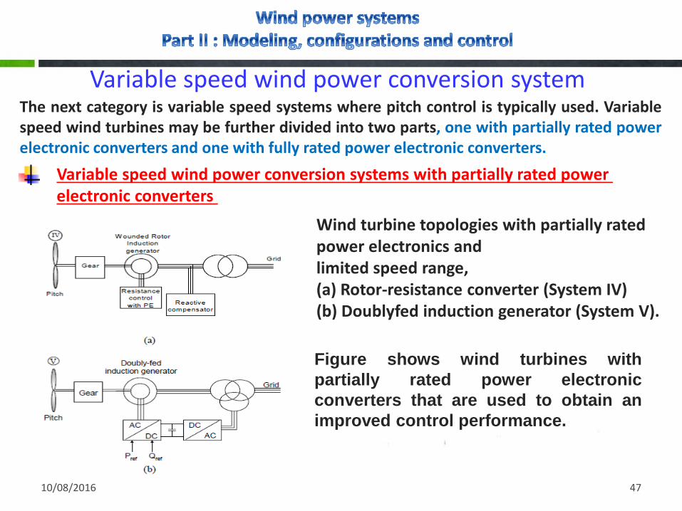
Variable speed wind power conversion systemThe next category is variable speed systems where pitch control is typically used. Variablespeed wind turbines may be further divided into two parts, one with partially rated powerelectronic converters and one with fully rated power electronic converters.
Variable speed wind power conversion systems with partially rated power electronic converters
Wind turbine topologies with partially rated power electronics andlimited speed range, (a) Rotor-resistance converter (System IV) (b) Doublyfed induction generator (System V).
Figure shows wind turbines with
partially rated power electronic
converters that are used to obtain an
improved control performance.
10/08/2016 48
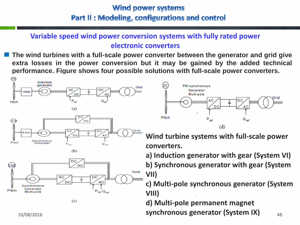
Variable speed wind power conversion systems with fully rated power electronic converters
The wind turbines with a full-scale power converter between the generator and grid give
extra losses in the power conversion but it may be gained by the added technicalperformance. Figure shows four possible solutions with full-scale power converters.
Wind turbine systems with full-scale power converters.a) Induction generator with gear (System VI)b) Synchronous generator with gear (System VII)c) Multi-pole synchronous generator (System VIII)d) Multi-pole permanent magnetsynchronous generator (System IX)

10/08/2016 49
Variable speed wind power conversion systemAll four solutions have the same controllable characteristics since the generator isdecoupled from the grid by a dc-link. The power converter to the grid enables thesystem very fast to control active and reactive power. However, the negative side isa more complex system with a more sensitive electronic part.
By introducing power electronics many of the wind turbine systems get aperformance like a power plant. In respect to control performance they are fasterbut of course the produced real power depends on the available wind. The reactivepower can in some solutions be delivered without having any wind.
Wind turbines act as a real power source for the grid. They are able to be activewhen a fault appears at the grid and so as to build the grid voltage up again quickly;the systems have the possibility to lower the power production even though morepower is available in the wind and thereby acting as a rolling capacity. Finally, someare able to operate in island operation in the case of a grid collapse.

10/08/2016 50
PROJECT CYCLE IN WIND PROJECT DEVELOPMENT

10/08/2016 51
10/08/2016 52

10/08/2016 53
Thank you for your attention