summary report of ecological risk ... - tri-valley cares
TRANSCRIPT

LLNL-TR-646919
Summary Report of Ecological Risk
Assessment for the Operation of the
Explosives Waste Treatment Facility
at Site 300 of the Lawrence Livermore
National Laboratory
Gretchen Gallegos Stan Terusaki
December 2013

This work was performed under the auspices of the U. S. Department of Energy by the University of California, Lawrence Livermore National Laboratory under Contract No. DE-AC52-07NA27344.

i
Table of Contents
BACKGROUND INFORMATION ABOUT TYPES OF EXPLOSIVES ..................................... III
EXECUTIVE SUMMARY ............................................................................................................ 4
INTRODUCTION ........................................................................................................................ 5
OB/OD OPERATIONS AT SITE 300 ......................................................................................... 5
ECOLOGICAL RISK ASSESSMENT APPROACH .................................................................. 6
IDENTIFICATION OF CHEMICALS OF POTENTIAL ECOLOGICAL CONCERN .................. 6
SOIL SAMPLING PLAN............................................................................................................. 7
SOIL SAMPLING RESULTS ..................................................................................................... 8
STATISTICAL EVALUATION OF CONSTITUENTS OF POTENTIAL ECOLOGICAL CONCERN .................................................................................................................................. 9
CONCLUSIONS ......................................................................................................................... 9
REFERENCES ......................................................................................................................... 11
APPENDIX A PERMIT RENEWAL MILESTONE DATES ...................................................... 12
APPENDIX B FIGURES ........................................................................................................... 13
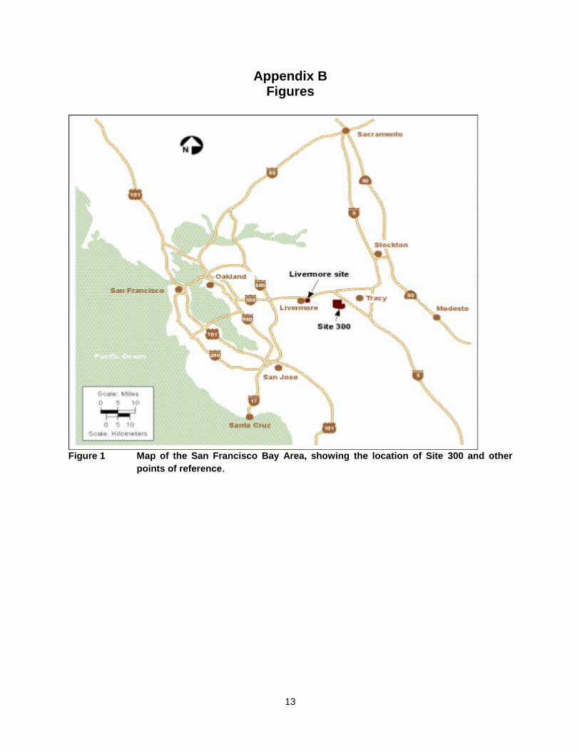
FIGURE 1 MAP OF THE SAN FRANCISCO BAY AREA, SHOWING THE LOCATION OF SITE 300 AND OTHER POINTS OF REFERENCE ................................................................ 13
FIGURE 2. EWTF DETONATION PAD. .................................................................................. 14
FIGURE 3. EWTF BURN PAN, COVERED. ............................................................................ 14
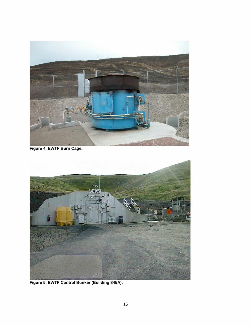
FIGURE 4. EWTF BURN CAGE. ............................................................................................. 15
FIGURE 5. EWTF CONTROL BUNKER (BUILDING 845A). .................................................. 15
FIGURE 6. LOCATION OF EWTF AT SITE 300. .................................................................... 16
FIGURE 7. SITE 300 ENVIRONS. ........................................................................................... 17
FIGURE 8. EWTF SOIL SAMPLING AREAS. ......................................................................... 18
FIGURE 9. EWTF AND CERCLA (ERD) SAMPLE LOCATIONS. HARDCOPY VERSIONS – 24” X 30” FIGURE PROVIDED IN PLASTIC SLEEVE FOLLOWING THIS PAGE. .............. 19
FIGURE 10. USDA SOIL TEXTURE TRIANGLE. .................................................................. 20
APPENDIX C TABLES ............................................................................................................ 21
TABLE 1. MASS AMOUNTS OF TREATED MATERIAL BY TREATMENT UNIT AND WASTE FORM EVALUATED. ................................................................................................. 21
TABLE 2. MATERIALS TESTED IN THE BANGBOX EXPERIMENTS, THE TREATMENT FREQUENCY AT THE EWTF, TYPE OF TREATMENT AT EWTF, AND ASSOCIATED EWTF WASTE FORM. ............................................................................................................. 22
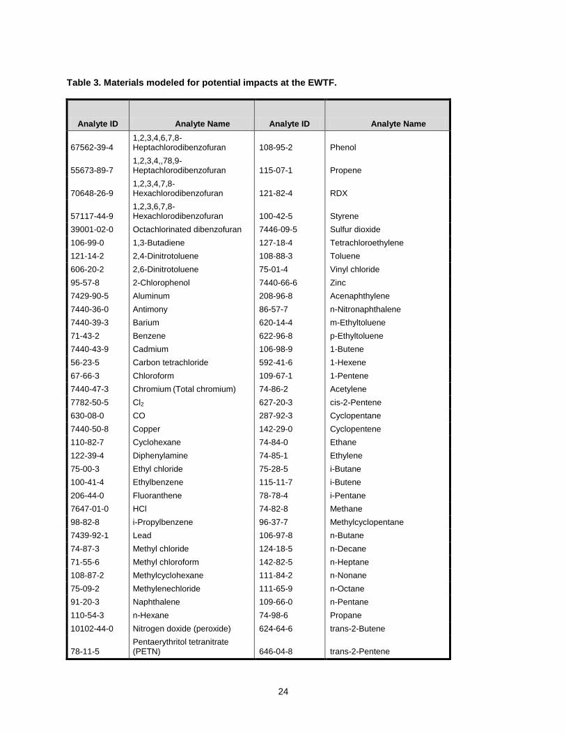
TABLE 3. MATERIALS MODELED FOR POTENTIAL IMPACTS AT THE EWTF. ............... 24
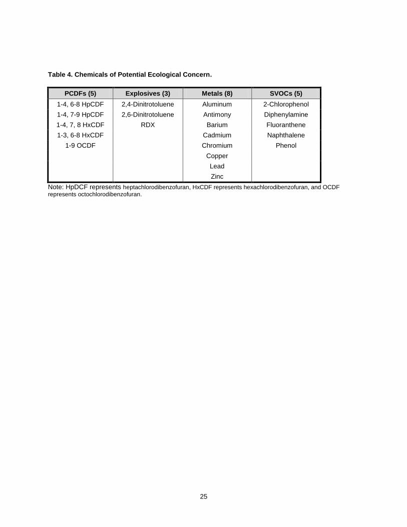
TABLE 4. CHEMICALS OF POTENTIAL ECOLOGICAL CONCERN. .................................. 25
TABLE 5. SAMPLE AREAS FOR THE BURN UNITS. ........................................................... 26
ii
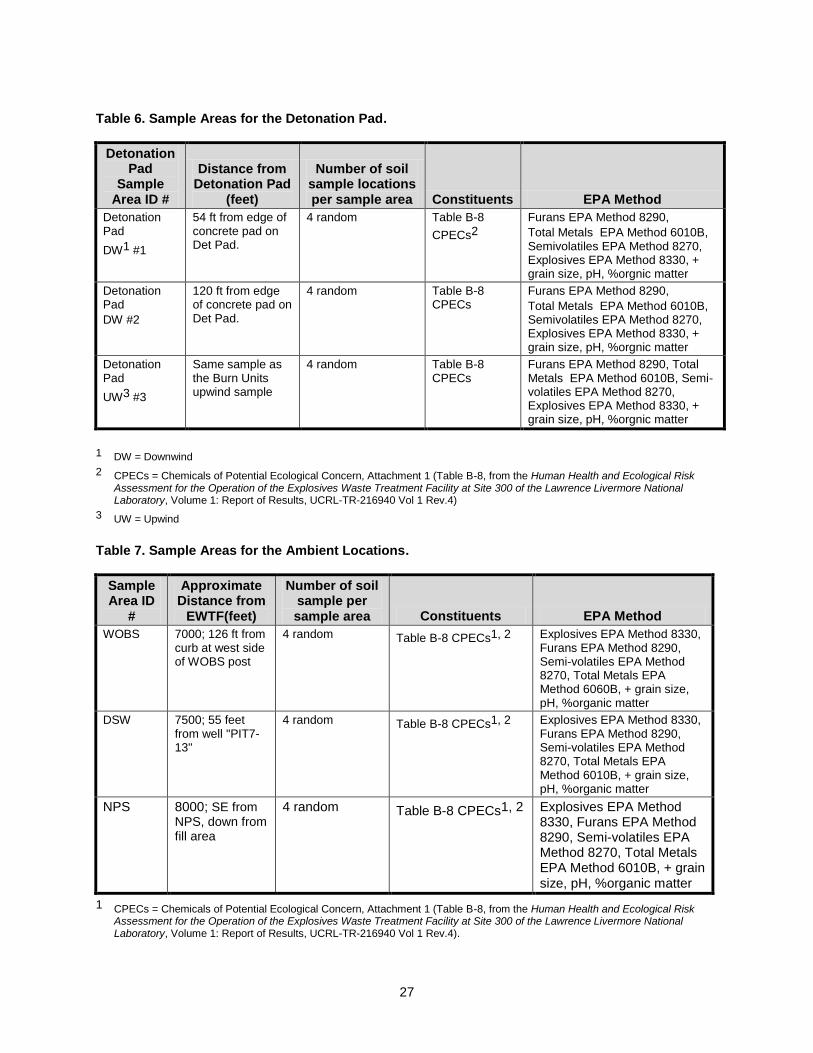
TABLE 6. SAMPLE AREAS FOR THE DETONATION PAD. ................................................. 27
TABLE 7. SAMPLE AREAS FOR THE AMBIENT LOCATIONS. .......................................... 27
TABLE 8. FURANS: CPEC, CAS NUMBER, LIMIT OF SENSITIVITY AND SUMMARY RESULTS. ................................................................................................................................ 28
TABLE 9. EXPLOSIVES: CPEC, CAS NUMBER, LIMIT OF SENSITIVITY AND SUMMARY RESULTS. ................................................................................................................................ 28
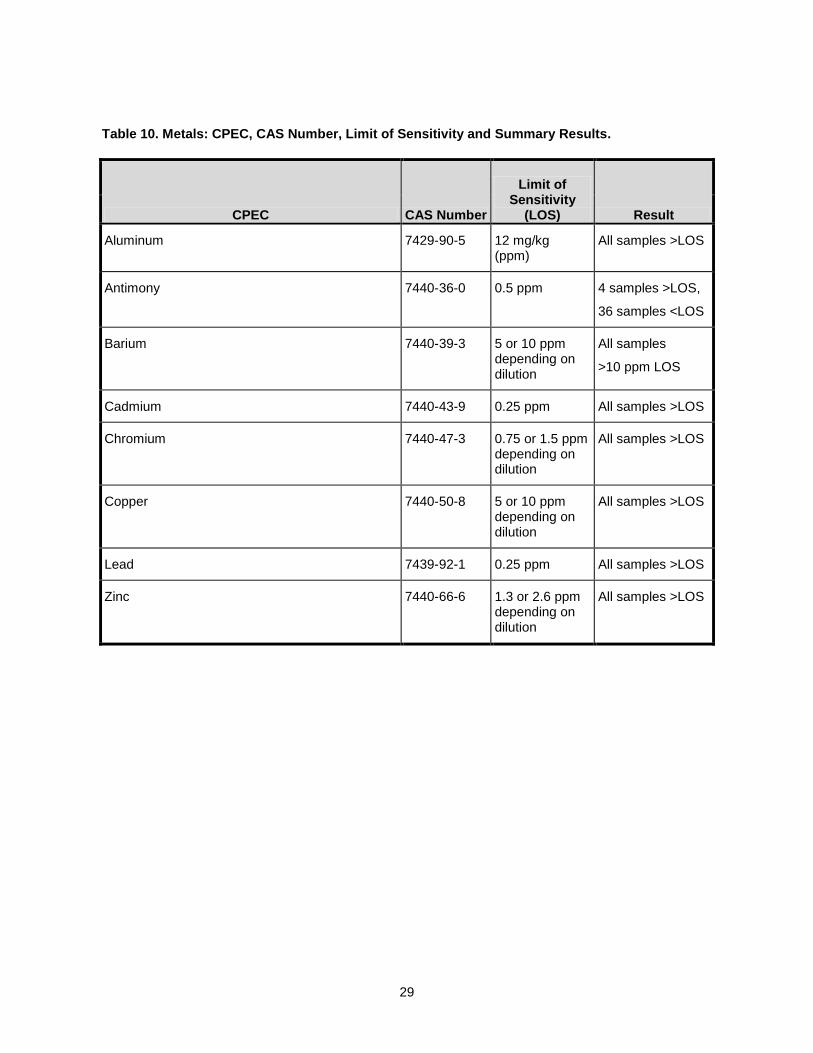
TABLE 10. METALS: CPEC, CAS NUMBER, LIMIT OF SENSITIVITY AND SUMMARY RESULTS. ................................................................................................................................ 29
TABLE 11. SEMI-VOLATILES: CPEC, CAS NUMBER, LIMIT OF SENSITIVITY AND SUMMARY RESULTS. ............................................................................................................ 30
TABLE 12. NUMBER OF SAMPLES YIELDING DETECTABLE RESULTS FOR EACH CPEC METAL. ......................................................................................................................... 30
TABLE 13. EWTF AREA AND AMBIENT SOIL TYPES. ....................................................... 30
TABLE 14. EWTF AREA AND BACKGROUND TOTAL ORGANIC CARBON AVERAGE, MAXIMUM, MINIMUM, AND STANDARD DEVIATION. ......................................................... 30
TABLE 15. 95% UCL EWTF AREA LEVELS COMPARED TO CERCLA BACKGROUND LEVELS. EACH ROW REPRESENTS ONE OF THE FOUR DISCRETE SAMPLING LOCATIONS IN THE SAMPLING AREA. ............................................................................... 31
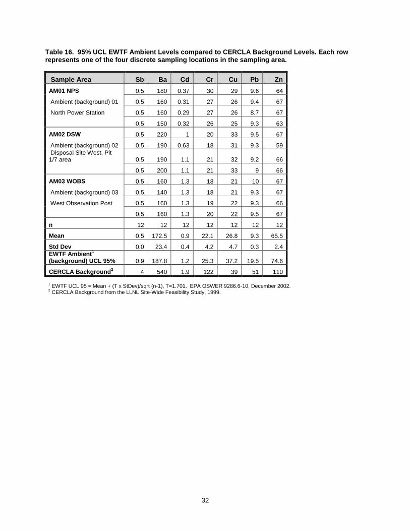
TABLE 16. 95% UCL EWTF AMBIENT LEVELS COMPARED TO CERCLA BACKGROUND LEVELS. EACH ROW REPRESENTS ONE OF THE FOUR DISCRETE SAMPLING LOCATIONS IN THE SAMPLING AREA. ............................................................................... 32
iii
Background Information about Types of Explosives
(adapted from Mitchell, 1999)
High Explosive. An energetic material in which the decomposition process (detonation wave) proceeds through the entire material at supersonic speed. The rate at which the detonation wave passes through the energetic material depends on a large number of parameters, including the density of the energetic material, the heat released by the detonation, the geometric shape or dimensions of the energetic material, the degree of confinement, and the purity of the energetic material(s). High explosives can be divided into two subcategories: primary high explosives that detonate easily when exposed to an ignition source, and secondary high explosives that require the detonation of a primary high explosive before they detonate. Fuses and boosting charges are examples of primary high explosives; trinitrotoluene (TNT), Research Department Explosive (RDX), tetryl, and nitroglycerin are examples of secondary explosives. Low Explosive. An energetic material in which the decomposition process (deflagration) occurs at subsonic speed. The decomposition occurs only on the surface of the energetic material, and, unlike the high explosive, there is no shock wave. The rate determining factors for decomposition of a low explosive are the rate of heat transfer into the energetic material from the decomposition occurring on its surface; and the rate of decomposition of the energetic material itself. The pressure the decomposition products exert on the energetic material also affects the rate of heat transfer. Low explosives are usually divided into three largely unrelated categories: black powder (a mixture of sulfur, charcoal and potassium nitrate), pyrotechnics (materials used to produce light, smoke, heat or sound effects), and propellants (materials used for the propulsion of projectiles or rockets). Propellant. A low explosive energetic material. Some of the most commonly used propellant ingredients are nitrocellulose, nitroglycerin, and ammonium perchlorate. Propellants are placed into five subcategories based on their energetic composition: (1) single base, which contains only nitrocellulose, (2) double-base, which contains nitrocellulose and nitroglycerin, (3) triple-base, which contains nitrocellulose, nitroglycerin, and nitroguanidine, (4) ammonium perchlorate, and (5) composite, which contains an oxidizer such as ammonium perchlorate and a metal additive (e.g., powdered aluminum) held together by a polymeric substance such as polybutadiene.

4
Summary Report of Ecological Risk Assessment for the Operation of the Explosives Waste Treatment
Facility at Site 300 of the Lawrence Livermore National Laboratory
Executive Summary
An ecological risk assessment is required as part of the Resource Recovery and Conservation Act (RCRA) permit renewal process for Miscellaneous Units subject to 22 CCR 66270.23. This risk assessment is prepared in support of the RCRA permit renewal for the Explosives Waste Treatment Facility (EWTF) at Site 300 of the Lawrence Livermore National Laboratory (LLNL). LLNL collected soil samples and used the resulting data to produce a scoping-level ecological risk assessment pursuant to the Department of Toxic Substances Control, Guidance for Ecological Risk Assessment at Hazardous Waste Sites and Permitted Facilities, Part A: Overview, July 4, 1996. The scoping-level ecological risk assessment provides a framework to determine the potential interaction between ecological receptors and chemicals of concern from hazardous waste treatment operations in the area of EWTF. A scoping-level ecological risk assessment includes the step of conducting soil sampling in the area of the treatment units. The Sampling Plan in Support of the Human Health and Ecological Risk Assessment for the Operation of the Explosives Waste Treatment Facility at Site 300 of the Lawrence Livermore National Laboratory, (Terusaki, 2007), outlines the EWTF project-specific soil sampling requirements. Soil samples were obtained and analyzed for constituents from four chemical groups: furans, explosives, semi-volatiles and metals. Analytical results showed that furans, explosives and semi-volatiles were not detected; therefore, no further analysis was conducted. The soil samples did show the presence of metals. Soil samples analyzed for metals were compared to site-wide background levels, which had been developed for site -wide cleanup activities pursuant to the Comprehensive Environmental Response, Compensation, and Liability Act (CERCLA). Total metal concentrations from 28 discrete soil samples obtained in the EWTF area were all below CERCLA-developed background levels. Therefore, following DTSC 1996 guidance, the EWTF hazardous waste treatment units exit the ecological risk evaluation process upon completion of the requirements of a scoping-level assessment report. This summary report documents that the requirements of a scoping-level assessment have been met.
1
5
Introduction
This document is a summary report of the ecological risk assessment for the Resource Recovery and Conservation Act (RCRA) permit renewal for the Explosives Waste Treatment Facility (EWTF). The EWTF is operated by the Lawrence Livermore National Laboratory (LLNL) at Site 300, located in the foothills between the cities of Livermore and Tracy, approximately 17 miles east of Livermore and 8 miles southwest of Tracy. (See Appendix B, Figure 1.) One of the principal functions at Site 300 is to test "high explosives" for nuclear weapons. These highly energetic materials provide the force to drive fissionable material to criticality. LLNL scientists develop and test the explosives and the integrated non-nuclear components in support of the nuclear stockpile stewardship program and conventional weapons, as well as in support of the aircraft, mining, oil exploration, and construction industries. Site 300 facilities are used to support chemical formulation of explosives, mechanical pressing explosives, radiographic inspection of material for cracks and voids, and assembly of machined charges before shipment to on-site test firing facilities. Wastes generated from high-explosives research are treated by open burning (OB) and open detonation (OD). OB and OD treatments are the safest methods for treating explosives wastes. If done correctly OB and OD eliminate the security issues and any requirement for further handling if the wastes were treated off site.
OB/OD Operations at Site 300 OB/OD operations are conducted at the Explosives Waste Treatment Facility (EWTF) located at the Building 845 Complex at Site 300. The EWTF consists of three units: the detonation pad, the burn pan, and the burn cage. The detonation pad (Appendix B, Figure 2) is used for the treatment of those waste explosives whose configuration requires treatment by open detonation, i.e., the wastes are in a form that cannot be safely treated by open burning. The materials treated are 90 to 100% explosive materials. The detonation pad consists of a level, 30-foot x 30-foot (9-m x 9-m) gravel pad with a minimum gravel pack about 8-feet (2.4-m) thick. Detonation of explosives waste is accomplished with the use of detonators or other initiating devices, and the process is controlled remotely from the Building 845 control bunker under observation by surveillance cameras. No more than 350 pounds (159 kg) of explosive waste (net explosive weight) may be detonated at one time. The detonation process is virtually instantaneous. The burn pan (Appendix B, Figure 3) is used for the treatment of small pieces and powders of explosives wastes; these materials are 80 to 100% explosive materials that will not detonate during the thermal treatment process. The burn pan is a 4-foot x 8-foot x 0.5-foot-deep rectangular, welded steel, watertight pan mounted on steel legs. The pan is equipped with a remotely controlled, removable cover. Pieces of explosives waste are placed in the pan, and cellulose material or other combustible materials are used to initiate treatment by burning. No more than 100 pounds (45 kg) of explosives waste (net explosive weight) may be treated at one time. The duration of the combustion treatment is 10 minutes or less. Site 300 personnel use the burn cage (Appendix B, Figure 4) for the treatment of explosives-containing process waste sludge, explosives-contaminated packaging, and explosives contaminated laboratory waste. The explosive content of the material treated in the burn cage ranges from 1 to 80%. The burn cage is an 8-foot diameter, ventilated, metal enclosure with a refractory lining and an elevated metal base. Propane fuel from a protected supply tank is supplied to the burn cage to assist the combustion process. No more than 260 pounds (118 kg) of total waste and 50 pounds (23 kg) net explosive waste may be treated in the burn cage at one time. Combustion treatments at the burn cage are completed in 35 minutes.
6
EWTF operations and controls are handled from a concrete and steel bunker (see Appendix B, Figure 5). Appendix B, Figure 6 shows the central location of the EWTF, which maximizes the distance to off-site receptors. The inset in the figure shows the relative locations of the detonation pad, the burn pan, and the burn cage. Appendix B, Figure 7 shows the Site 300 environs.
Ecological Risk Assessment Approach The Human and Ecological Risk Division (HERD) of DTSC has developed a tiered approach for ecological risk assessments at permitted facilities. The goal of the ecological risk assessment is to predict potential adverse effects and, when appropriate, to measure existing adverse effects of chemical contaminants on the biota on or near a facility and to determine levels of those chemicals in the environment that would not be expected to adversely affect the biota. In order to allocate resources in proportion to potential ecological threats, a phased approach is suggested, with progression to the subsequent phases dependent, in part, on the results of the preceding phase (DTSC, 1996a). The first suggested phase for an ecological risk assessment is the initial scoping assessment. The initial scoping assessment of potential ecological risk is meant to determine the potential contaminants of concern, the potential ecological receptors, and the potentially complete exposure pathways. The identification of potential chemicals of ecological concern is the point at which a potentially responsible party may choose to demonstrate that inorganic contaminants are present at background concentrations and that the facility poses no greater risk than the surrounding unimpacted area. If organic chemicals of ecological concern are present or concentrations of inorganic elements are present above background concentrations the Scoping Assessment proceeds to identify the potentially affected habitats or communities. If no organic chemicals of ecological concern are present or concentrations of inorganic elements are at or below background concentrations the facility or site exits from the ecological risk assessment process upon preparation and acceptance of a minimal Scoping Assessment report detailing these findings and conclusions (DTSC, 1996b). This summary report documents the initial scoping assessment for LLNL’s EWTF. It begins with the identification of the chemicals of concern; describes the soil sampling plan upon which the risk determination will be made; presents the results of the soil sampling event; and documents that organic chemicals of concern were not detected and that the inorganic chemicals of concern are below background. The ecological risk assessment process for the EWTF actually began with a predictive risk assessment that was completed before the soil sampling. Because the results of the soil sampling demonstrate that there are no organic chemicals of ecological concern and that the inorganic chemicals are below background, no additional work on the predictive risk assessment is necessary. For a timeline of events associated with the ecological risk assessment for EWTF see Appendix A.
Identification of Chemicals of Potential Ecological Concern The EWTF a support facility at LLNL’s Site 300, treats the wastes resulting from research activities involving explosives. Most of the explosive wastes involve high explosives, such as the compounds RDX, high melting explosive (HMX), pentaerythritol tetranitrate (PETN), and trinitrotoluene (TNT) in a variety of formulations. Rarely, this facility treats explosives other than high explosives. The wastes treated are categorized into four forms, which are described below. Form 1 Waste. This type of waste explosives is best treated by open detonation because of its configuration or composition. Examples are explosive assemblies or devices that may detonate during open burning.
Form 2 Waste. Waste explosives that because of configuration or composition are best treated by open burning in the open burn pan. Examples are explosive parts and pieces generated during explosives formulation, processing, testing, or by removal from inventory.
7
Form 3 Waste. Waste explosives that because of configuration or composition are best treated by open burning in the thermal treatment unit (burn cage). Examples are wet machine fines generated during explosives processing, wet explosives-contaminated sludge from weirs and settling basins, and wet expendable filters from recycle systems.
Form 4 Waste. Waste material contaminated with energetic materials that are best treated by open burning in the thermal treatment unit (burn cage). Examples are paper, rags, plastic tubing, dry expendable filters from vacuum systems, and personal protective equipment used in explosives operations. The waste is judged to retain explosives hazards and is therefore considered to be a reactive waste.
Current permit limits allow 100 open detonations (Form 1 waste) and 100 open burn treatments (Forms 2, 3, or 4) annually. Appendix C, Table 1 presents the mass amounts of treated material by treatment unit and waste form. These mass amounts were evaluated for the purposes of impacts assessment, actual amounts treated at the EWTF have been, and are anticipated to continue to be, much less than the permitted amounts. The emissions estimates for the EWTF-treated materials were based on emission factors from OB/OD experiments conducted in a “BangBox” (an enclosed chamber where munitions were detonated, and the air sampled and analyzed for emissions) at Dugway Proving grounds in Dugway, UT. The emission factors have been approved by the U.S. EPA (Mitchell and Suggs, 1998). For this ecological risk assessment, LLNL began with identifying the materials that would be treated at EWTF, based on the tested materials in the OBODM model (Bjorkland et al., 1998), which was developed expressly for modeling OB/OD operations. The list of materials tested is presented in Appendix C, Table 2. LLNL evaluated the list of materials and determined which munitions would be representative of the materials treated at EWTF and the frequency of treatment. Because the OBODM model database linked the potential emitted chemicals to the specific munitions, LLNL staff used the OBODM model to identify the associated emissions of chemicals of potential ecological concern, see Appendix C, Table 3. The emission of each chemical was modeled and its soil concentration over a 6-inch depth predicted. The final list of potential chemicals of ecological concern is presented in Appendix C, Table 4. (For a more detailed discussion of this process, see section 3.1 and section 4 of the HHRA, Gallegos et al., 2007.).
Soil Sampling Plan
To determine if the organic chemicals of potential ecological concern were present and if the inorganic chemicals of potential ecological concern were at above-background levels, LLNL conducted soil sampling at 40 discrete locations within 10 sampling areas near the EWTF to capture the potential impacts of the burn units and the detonation unit. Each sampling area was represented by four randomly selected discrete locations; the selection of sampling areas is described below. A stand-alone soil sampling plan (Terusaki, 2007), which includes an implementation appendix was submitted to DTSC on January 14, 2008.
Four sample areas were chosen to represent the burn units. Three sample areas were located in the valley downgradient and east of the burn units. The downgradient direction also coincided with the predominantly easterly wind direction during treatment operations. Therefore, chemicals of potential ecological concern, if present, would most likely be carried downwind and downgradient by wind and erosional processes. The fourth downwind sample area was located near a ridge before crossing into another small valley. This represented the last area where chemicals of potential ecological concern would be deposited before dilution by dispersion effects of the ridge east of the Burn Units.
An upwind sample area, approximately 850 feet west of the burn units, near the top of a ridge surrounding EWTF was also identified. This sample area also served as the upwind sample for the Detonation Pad. Appendix C, Table 5 summarizes the sampling plan for the Burn Units.
8
Because of the shorter distance from the detonation to the ridge of approximately 180 feet, only two sample areas were identified for the detonation pad. Appendix C, Table 6 summarizes the sampling plan for the Detonation Pad. In addition, three sampling areas were proposed to evaluate ambient levels. These areas were selected in the west to northwest corner of Site 300, approximately 7000 to 8000 feet upwind of the EWTF. Soil types were identified to attempt minimize the effects of different chemical, mechanical weathering processes and source terrain influences on the sample results. Appendix C, Table 7 summarizes the sampling plan for the ambient locations. Appendix B, Figure 8 shows the locations of the 10 soil sampling areas The soil samples were collected at a depth of 0 to 6 inches. This depth was chosen to be representative of exposure of plants and burrowing animals that live in the soil, which is quite unconsolidated in the area of the EWTF. The limit of sensitivity for the chemical analyses for the chemicals of potential ecological concern (identified in Appendix C, Table 4) was chosen to be the practical quantitation limit, i.e., the value where the analytical laboratory is able to stand behind the result as a true quantification.
Soil Sampling Results Soil samples were obtained and analyzed from four chemical groups: furans, explosives, semi-volatiles and metals. EPA Methods and detection limits were chosen for the appropriate soil matrix and to achieve the lowest, reproducible analytical result. The Appendix C, Tables 8 through 11 provides CPEC name, corresponding Chemical Abstract Services (CAS) number, and a qualitative comparison of Limit of Sensitivity to the results for each of the groups of chemical analytes: furans, explosives, metals, and semi-volatiles.
The furans, explosives and semi-volatiles results were all below the limit of sensitivity of the laboratory analytical equipment. Therefore, additional statistical analysis was not performed on the 13 CPECs belonging to the furans, explosives and semi-volatile compound chemical groups. Aluminum analysis was conducted on all 40 samples. The average concentration was 23,075 mg/kg, or 23%. Aluminum is the most commonly occurring metal in the Earth’s crust, with concentration ranging from 1% to 30%. Although the concentration of aluminum is high relative to other metals, aluminum bearing minerals do not start to dissociate until soil pH lowers to 5.5. As the concentration of soluble aluminum increases, the toxicity also increases. However, in neutral soil pH environments, aluminum bearing minerals are stable and therefore do not pose a toxicity hazard. The average pH of 40 samples obtained in the EWTF and background areas is 7.5. Therefore, in this pH neutral to slightly basic environment, aluminum would not be found in the soluble, toxic state.
The remaining seven CPEC metals were evaluated against background metal levels that were developed as part of LLNL’s Comprehensive, Emergency Response and Compensation Liability Act (CERCLA) site-wide clean-up activities. The CERCLA soil samples were obtained from locations across the entire site, as shown in the Appendix B, Figure 8. EWTF sample locations are also shown in the same figure. Appendix C, Table 12 shows the number of analytical results in the CERCLA background dataset for each CPEC metal.
A comprehensive description of the CERCLA background study is provided in Appendix 4, Site-Wide Feasibility Study for LLNL Site 300, Appendix A, November 1999. This 1999 background data is still used to evaluate analytical data from construction projects, CERCLA background determinations, and is a

9
key reference document in the EPA, DTSC, and RWQCB-approved Site-Wide Record of Decision, Lawrence Livermore National Laboratory, Site 300, July 2008.
Additional Soil Sampling Data Soil particle analysis by ASTM Method D422 was conducted on all soil samples to classify the soil texture by standard United States Department of Agriculture (USDA) terminology. The purpose of this test was to ensure consistency of soil sample texture relative to particle size. Soil texture is a qualitative classification tool used in to classify soils based on their physical texture. Samples obtained in the EWTF area grouped in the middle to bottom middle of the USDA soil texture triangle, Appendix B, Figure 10. Samples obtained in the EWTF ambient areas were more widely distributed. Appendix C, Table 4 shows the distribution of soil types, location and number of samples in each soil type.
Total Organic Compound (TOC) analysis was determined by EPA Method 9060. This test was requested by DTSC in order to identify differences in TOC between the samples. The following table shows the average, maximum, minimum and standard deviation % values for the 28 EWTF area samples and the 12 ambient area samples. Significant differences are not apparent, as summarized in Appendix C, Table 14.
Statistical Evaluation of Constituents of Potential Ecological Concern The 95% Upper Confidence Level (95% UCL) was calculated for the seven EWTF sample areas for eventual comparison to the CERCLA background data. In addition, the 95% UCL was calculated for the three ambient areas. The 95% UCL statistical method was selected as statistical methodology according guidance provided in the Environmental Protection Agency, Office or Solid Waste and Emergency Response document Calculating Upper Confidence Limits For Exposure Point Concentrations At Hazardous Waste Sites, OSWER 9286.6-10, December 2002. The 95% UCL value was calculated for each metal from the seven EWTF areas. Based on the sample strategy, the four EWTF downwind locations, two downwind Detonation Pad locations and the one EWTF upwind location were used for the 95% UCL value. A total of 28 (seven areas with four discrete soil samples per area) sample concentrations were included in the 95% UCL calculation. Appendix C, Table 15 provides the result for each metal. CERCLA background levels are also included in order to allow direct comparison. All EWTF area levels are below CERCLA background levels. The 95% UCL values were also calculated for the EWTF ambient samples. All EWTF ambient 95% UCL levels are below the CERCLA background levels. However, this comparison of EWTF ambient to CERCLA background is of limited value, based on the large difference in dataset size, and the large difference in sample locations. Many more samples would be required over a large area in order to determine if the 95% UCL levels of the EWTF dataset would converge to the CERCLA levels Prior to submission of the soil sampling results in this summary report LLNL submitted a soil sample report (Terusaki et al., 2012) to DTSC on October 8, 2012.
Conclusions According to DTSC guidance provided in Guidance for Ecological Risk Assessment at Hazardous Waste Sites and Permitted Facilities, Part A: Overview, July 4, 1996, page 13: “If no organic chemicals of ecological concern are present or concentrations of inorganic elements are at or below ‘background’ concentrations, the site or facility exits the risk assessment process upon preparation and acceptance of a minimal scoping assessment report detailing these findings and conclusions.”
10
Based on the non-detection results of the furans, explosives and semi-volatile analyses, the insoluble chemical form of aluminum due to the neutral pH soil environment, and the below background levels of the remaining metals, the EWTF area meets the requirements to exit the ecological risk assessment process as stated in the 1999 DTSC guidance document, and the information provided in this report provides substantial documentation fulfilling the requirements of a scoping-level report.

11
References
Bjorklund, J. R., J. F. Bowers, G. C. Dodd, and J. M. White (1998), Open Burn/Open Detonation Dispersion Model (OBODM) User's Guide, West Desert Test Center, Dugway Proving Ground, Dugway, UT (DPG Document No. DPG-TR-96-008a) (http://www.epa.gov/scram001/tt22.htm ).
Department of Toxic Substances Control (DTSC), Guidance for Ecological Risk Assessment at Hazardous Waste Sites and Permitted Facilities, Part A: Overview (DTSC Human and Ecological Risk Division, July 4, 1996a). Department of Toxic Substances Control (DTSC), Guidance for Ecological Risk Assessment at Hazardous Waste Sites and Permitted Facilities, Part B: Scoping Assessment (DTSC Human and Ecological Risk Division, July 4, 1996b). Gallegos, G., J. I. Daniels, and A. M. Wegrecki, Human Health and Ecological Risk Assessment for the Operation of the Explosives Waste Treatment Facility at Site 300 of the Lawrence Livermore National Laboratory, Volume 1: Report of Results, (Lawrence Livermore National Laboratory, UCRL-TR-216940 Vol 1 Rev.4, 2007). LLNL Environmental Restoration Department, Site-Wide Record of Decision, Lawrence Livermore National Laboratory, Site 300 (Lawrence Livermore National Laboratory, UCRL-AR-236665, July 2008). Mitchell, W.J., and J.C. Suggs (1998), Emission Factors for the Disposal of Energetic Materials by Open Burning and Open Detonation (OB/OD), U.S. Environmental Protection Agency, MD-46, Research Triangle Park, NC 27711, (EPA/600/R-98-103).
Mitchell, W.J. (1999), State of the Science and Research Needs in the Characterization and Minimization of the Emissions from Ordnance Use and Disposal Activities, Strategic Environmental Research and Development Workshop, June 2-4, 1999, co-sponsored by American Academy of Environmental Engineers, http://www.aaee.net/newlook/air_quality_issues.htm .
Terusaki, S., Sampling Plan in Support of the Human Health and Ecological Risk Assessment for the Operation of the Explosives Waste Treatment Facility at Site 300 of the Lawrence Livermore National Laboratory, (Lawrence Livermore National Laboratory, LLNL-TR-400074, October 2007). Terusaki, S. G.M. Gallegos, D.H. MacQueen, Soil Sampling Report in Support of the Site 300 Explosives Waste Treatment Facility Ecological Risk Assessment and Permit Renewal, (Lawrence Livermore National Laboratory, LLNL-TR-588454, September 2012). U.S. Environmental Protection Agency, Office or Solid Waste and Emergency Response, Calculating Upper Confidence Limits For Exposure Point Concentrations At Hazardous Waste Sites, OSWER 9286.6-10, December 2002.
12
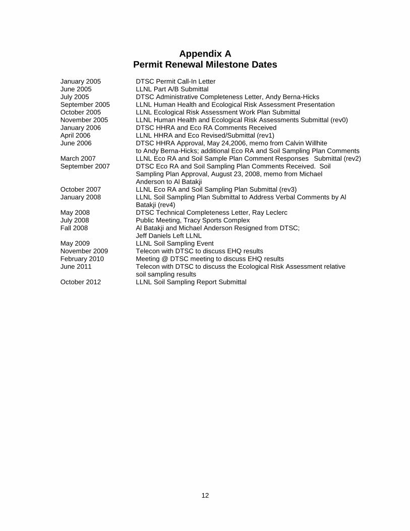
Appendix A Permit Renewal Milestone Dates
January 2005 DTSC Permit Call-In Letter June 2005 LLNL Part A/B Submittal July 2005 DTSC Administrative Completeness Letter, Andy Berna-Hicks September 2005 LLNL Human Health and Ecological Risk Assessment Presentation October 2005 LLNL Ecological Risk Assessment Work Plan Submittal November 2005 LLNL Human Health and Ecological Risk Assessments Submittal (rev0) January 2006 DTSC HHRA and Eco RA Comments Received April 2006 LLNL HHRA and Eco Revised/Submittal (rev1) June 2006 DTSC HHRA Approval, May 24,2006, memo from Calvin Willhite to Andy Berna-Hicks; additional Eco RA and Soil Sampling Plan Comments March 2007 LLNL Eco RA and Soil Sample Plan Comment Responses Submittal (rev2) September 2007 DTSC Eco RA and Soil Sampling Plan Comments Received. Soil Sampling Plan Approval, August 23, 2008, memo from Michael Anderson to Al Batakji October 2007 LLNL Eco RA and Soil Sampling Plan Submittal (rev3) January 2008 LLNL Soil Sampling Plan Submittal to Address Verbal Comments by Al
Batakji (rev4) May 2008 DTSC Technical Completeness Letter, Ray Leclerc July 2008 Public Meeting, Tracy Sports Complex Fall 2008 Al Batakji and Michael Anderson Resigned from DTSC;
Jeff Daniels Left LLNL May 2009 LLNL Soil Sampling Event November 2009 Telecon with DTSC to discuss EHQ results February 2010 Meeting @ DTSC meeting to discuss EHQ results June 2011 Telecon with DTSC to discuss the Ecological Risk Assessment relative soil sampling results October 2012 LLNL Soil Sampling Report Submittal
13
Appendix B Figures
Figure 1 Map of the San Francisco Bay Area, showing the location of Site 300 and other
points of reference.

14
Figure 2. EWTF Detonation Pad.
Figure 3. EWTF Burn Pan, covered.
15
Figure 4. EWTF Burn Cage.
Figure 5. EWTF Control Bunker (Building 845A).

16
Figure 6. Location of EWTF at Site 300.

17
Figure 7. Site 300 environs.

18
Figure 8. EWTF soil sampling areas.

19
Figure 9. EWTF and CERCLA (ERD) Sample Locations. Hardcopy versions – 24” x 30” figure provided in plastic sleeve at the end of this report.

20
Figure 10. USDA Soil Texture Triangle.

21
Appendix C Tables
Table 1. Mass amounts of treated material by treatment unit and waste form evaluated.
Treatment unit/Waste form Annual number of treatments
Maximum single
treatment (lb) Annual
treatment (lb)
Detonation Pad/Form 1 100 350 35,000 Burn Pan/Form 2 100 100 10,000 Burn Cage/Form 3 100 50 5,000 Burn Cage/Form 4 100 260 26,000

22
Table 2. Materials tested in the BangBox experiments, the treatment frequency at the EWTF, type of treatment at EWTF, and associated EWTF waste form.
Tested material
Frequency of material
a
treatment at EWTF
Type of treatment at
EWTF EWTF waste
form
TNT (2,4,6-Trinitrotoluene) Routinely treated Detonation Pad (Form 1), Burn Pan (Form 2)
1 and 2
RDX (cyclotrimethylenetrinitramine) Routinely treated Detonation Pad (Form 1), Burn Pan (Form 2)
1 and 2
Manufacturer's Waste (65% propell.) Routinely treated Burn Cage 3 and 4
Triple Base (M30-28% Nitrocellulose <5% Burn Pan 2
M1 (85% Nitrocellulose) <5% Burn Pan 2
Double Base (50% nitrocellulose) <5% Burn Pan 2
Propellant, ammonium perc., alum. <5% Burn Pan 2
Propellant, ammonium perc., nonal. <5% Burn Pan 2
Propellant, M-43 <5% Burn Pan 2
Propellant, M-9 <5% Burn Pan 2
Propellant, MK-23 <5% Burn Pan 2
Propellant, M31A1E1 <5% Burn Pan 2
Propellant, PBXN-110 <5% Burn Pan 2
Smokeless Powder <5% Burn Pan 2
Propellant, Composite (MK-6) <5% Burn Pan 2
Propellant, M-3 <5% Burn Pan 2
M6 (87.7% Nitrocellulose) <5% Burn Pan 2
Explosive D (ammonium picrate) <5% Detonation Pad (Form 1), Burn Pan (Form 2)
1 and 2
Composition B (56/38/6 RDX-TNT-WAX) <1% Detonation Pad 1
Tritonal (79% TNT, 21% Aluminum) <1% Detonation Pad 1
Tritonal with 2.5% Calcium Stearate <1% Detonation Pad 1
Amatol (50% TNT, 50% Ammn. Nitrate) <1% Detonation Pad 1
HBX (48/31/17/4 RDX-TNT-Al-WAX) <1% Detonation Pad 1
Propellant, Smokey Sam <1% Burn Pan 2
Detonating train
Only with additional internal review
Detonation Pad
1
40 mm HEI Cartridge Only with additional internal review
Detonation Pad 1
Ground Illum. Signal, Red Star, M158 Not treated Not treated Not applicable
Signal, Illum, Arcrft, Rd Str, AN-M43A2 Not treated Not treated Not applicable
20 mm HEI Cartridge Not treated Not treated Not applicable
Impluse Cartridge, ARD 446-1 Not treated Not treated Not applicable
Impluse BBU-368 Cartridge Not treated Not treated Not applicable
GGU-2/A Gas prss Prop. Act. Gen. Not treated Not treated Not applicable

23
Tested material
Frequency of material
a
treatment at EWTF
Type of treatment at
EWTF EWTF waste
form
‘Impulse Cartridge, MK107 MOD01 Not treated Not treated Not applicable
Fuze, Inertia Tail, Bomb, FMU 54A/B Not treated Not treated Not applicable
Flare, Cntermeas., Aircraft, M206 Not treated Not treated Not applicable
Fuze, Bomb, Tail, FMU 139A/B Not treated Not treated Not applicable
Mine, Claymore, M18A1 Not treated Not treated Not applicable
T45E7 Adapter Booster Not treated Not treated Not applicable
Diesel and Dunnage Not treated Not treated Not applicable
a Material representative of materials treated at EWTF.
24
Table 3. Materials modeled for potential impacts at the EWTF.
Analyte ID Analyte Name Analyte ID Analyte Name
67562-39-4 1,2,3,4,6,7,8-Heptachlorodibenzofuran 108-95-2 Phenol
55673-89-7 1,2,3,4,,78,9-Heptachlorodibenzofuran 115-07-1 Propene
70648-26-9 1,2,3,4,7,8-Hexachlorodibenzofuran 121-82-4 RDX
57117-44-9 1,2,3,6,7,8-Hexachlorodibenzofuran 100-42-5 Styrene
39001-02-0 Octachlorinated dibenzofuran 7446-09-5 Sulfur dioxide
106-99-0 1,3-Butadiene 127-18-4 Tetrachloroethylene
121-14-2 2,4-Dinitrotoluene 108-88-3 Toluene
606-20-2 2,6-Dinitrotoluene 75-01-4 Vinyl chloride
95-57-8 2-Chlorophenol 7440-66-6 Zinc
7429-90-5 Aluminum 208-96-8 Acenaphthylene
7440-36-0 Antimony 86-57-7 n-Nitronaphthalene
7440-39-3 Barium 620-14-4 m-Ethyltoluene
71-43-2 Benzene 622-96-8 p-Ethyltoluene
7440-43-9 Cadmium 106-98-9 1-Butene
56-23-5 Carbon tetrachloride 592-41-6 1-Hexene
67-66-3 Chloroform 109-67-1 1-Pentene
7440-47-3 Chromium (Total chromium) 74-86-2 Acetylene
7782-50-5 Cl2 627-20-3 cis-2-Pentene
630-08-0 CO 287-92-3 Cyclopentane
7440-50-8 Copper 142-29-0 Cyclopentene
110-82-7 Cyclohexane 74-84-0 Ethane
122-39-4 Diphenylamine 74-85-1 Ethylene
75-00-3 Ethyl chloride 75-28-5 i-Butane
100-41-4 Ethylbenzene 115-11-7 i-Butene
206-44-0 Fluoranthene 78-78-4 i-Pentane
7647-01-0 HCl 74-82-8 Methane
98-82-8 i-Propylbenzene 96-37-7 Methylcyclopentane
7439-92-1 Lead 106-97-8 n-Butane
74-87-3 Methyl chloride 124-18-5 n-Decane
71-55-6 Methyl chloroform 142-82-5 n-Heptane
108-87-2 Methylcyclohexane 111-84-2 n-Nonane
75-09-2 Methylenechloride 111-65-9 n-Octane
91-20-3 Naphthalene 109-66-0 n-Pentane
110-54-3 n-Hexane 74-98-6 Propane
10102-44-0 Nitrogen doxide (peroxide) 624-64-6 trans-2-Butene
78-11-5 Pentaerythritol tetranitrate (PETN) 646-04-8 trans-2-Pentene
25
Table 4. Chemicals of Potential Ecological Concern.
PCDFs (5) Explosives (3) Metals (8) SVOCs (5)
1-4, 6-8 HpCDF 2,4-Dinitrotoluene Aluminum 2-Chlorophenol
1-4, 7-9 HpCDF 2,6-Dinitrotoluene Antimony Diphenylamine
1-4, 7, 8 HxCDF RDX Barium Fluoranthene
1-3, 6-8 HxCDF Cadmium Naphthalene
1-9 OCDF Chromium Phenol
Copper
Lead
Zinc
Note: HpDCF represents heptachlorodibenzofuran, HxCDF represents hexachlorodibenzofuran, and OCDF
represents octochlorodibenzofuran.

26
Table 5. Sample Areas for the Burn Units.
Burn Units Sample
Area ID #
Distance from Burn Units
(feet)
Number of soil sample locations per sample area Constituents EPA Method
Burn Units
DW1 #1
78 ft from storm drain pipe (outlet)
4 random Table B-8
CPECs2
Explosives EPA Method 8330,
Furans EPA Method 8290,
Total Metals EPA Method 6010B,
Semi-volatiles EPA Method 8270, + grain size, pH, %organic matter
Burn Units
DW #2
250 ft from storm drain pipe (outlet)
4 random Table B-8 CPECs
Explosives EPA Method 8330,
Furans EPA 8290,
Total Metals EPA Method 6010B,
Semi-volatiles EPA Method 8270, + grain size, pH, %organic matter
Burn Units
DW #3
450 ft from storm drain pipe (outlet)
4 random Table B-8 CPECs
Explosives EPA Method 8330,
Furans EPA Method 8290,
Total Metals EPA Method 6010B,
Semi-volatiles EPA Method 8270, + grain size, pH, %organic matter
Burn Units
DW #4
500 ft from storm drain pipe (outlet)
4 random
Table B-8 CPECs
Explosives EPA Method 8330,
Furans EPA Method 8290,
Total Metals EPA Method 6010B,
Semi-volatiles EPA Method 8270, + grain size, pH, %organic matter
Burn Units and Detonation Pad
UW3 #1
750 ft from the
corner of the burn
unit fence
4 random Table B-8 CPECs
Explosives EPA Method 8330,
Furans EPA Method 8290,
Total Metals) EPA Method 6010B,
Semi-volatiles EPA Method 8270, + grain size, pH, %organic matter
1 DW = Downwind
2 CPECs = Chemicals of Potential Ecological Concern, Attachment 1 (Table B-8, from the Human Health and Ecological Risk Assessment for the Operation of the Explosives Waste Treatment Facility at Site 300 of the Lawrence Livermore National Laboratory, Volume 1: Report of Results, UCRL-TR-216940 Vol 1 Rev.4)
3 UW = Upwind
27
Table 6. Sample Areas for the Detonation Pad.
Detonation Pad
Sample Area ID #
Distance from Detonation Pad
(feet)
Number of soil sample locations per sample area Constituents EPA Method
Detonation Pad
DW1 #1
54 ft from edge of concrete pad on Det Pad.
4 random Table B-8
CPECs2
Furans EPA Method 8290,
Total Metals EPA Method 6010B, Semivolatiles EPA Method 8270, Explosives EPA Method 8330, + grain size, pH, %orgnic matter
Detonation Pad
DW #2
120 ft from edge of concrete pad on Det Pad.
4 random Table B-8 CPECs
Furans EPA Method 8290,
Total Metals EPA Method 6010B, Semivolatiles EPA Method 8270, Explosives EPA Method 8330, + grain size, pH, %orgnic matter
Detonation Pad
UW3 #3
Same sample as the Burn Units upwind sample
4 random Table B-8 CPECs
Furans EPA Method 8290, Total Metals EPA Method 6010B, Semi-volatiles EPA Method 8270, Explosives EPA Method 8330, + grain size, pH, %orgnic matter
1 DW = Downwind
2 CPECs = Chemicals of Potential Ecological Concern, Attachment 1 (Table B-8, from the Human Health and Ecological Risk Assessment for the Operation of the Explosives Waste Treatment Facility at Site 300 of the Lawrence Livermore National Laboratory, Volume 1: Report of Results, UCRL-TR-216940 Vol 1 Rev.4)
3 UW = Upwind
Table 7. Sample Areas for the Ambient Locations.
Sample Area ID
#
Approximate Distance from
EWTF(feet)
Number of soil sample per sample area Constituents EPA Method
WOBS 7000; 126 ft from curb at west side of WOBS post
4 random Table B-8 CPECs1, 2
Explosives EPA Method 8330, Furans EPA Method 8290, Semi-volatiles EPA Method 8270, Total Metals EPA Method 6060B, + grain size, pH, %organic matter
DSW 7500; 55 feet from well "PIT7-13"
4 random Table B-8 CPECs1, 2
Explosives EPA Method 8330, Furans EPA Method 8290, Semi-volatiles EPA Method 8270, Total Metals EPA Method 6010B, + grain size, pH, %organic matter
NPS 8000; SE from NPS, down from fill area
4 random Table B-8 CPECs1, 2
Explosives EPA Method 8330, Furans EPA Method 8290, Semi-volatiles EPA Method 8270, Total Metals EPA Method 6010B, + grain size, pH, %organic matter
1 CPECs = Chemicals of Potential Ecological Concern, Attachment 1 (Table B-8, from the Human Health and Ecological Risk Assessment for the Operation of the Explosives Waste Treatment Facility at Site 300 of the Lawrence Livermore National Laboratory, Volume 1: Report of Results, UCRL-TR-216940 Vol 1 Rev.4).

28
Table 8. Furans: CPEC, CAS Number, Limit of Sensitivity and Summary Results.
CPEC CAS
Number
Limit of Sensitivity
(LOS) Result
1,2,3,4,6,7,8-Heptachlorodibenzofuran 67562-39-4 10 ng/kg (ppt) All samples <LOS
1,2,3,4,7,8,9-Heptachlorodibenzofuran 55673-89-7 10 ppt All samples <LOS
1,2,3,4,7,8-Hexachlorodibenzofuran 70648-26-9 10 ppt All samples <LOS
1,2,3,6,7,8-Hexachlorodibenzofuran 57117-44-9 10 ppt All samples <LOS
1,2,3,4,6,7,8,9-Octachlorodibenzofuran 39001-02-0 20 ppt All samples <LOS
Table 9. Explosives: CPEC, CAS Number, Limit of Sensitivity and Summary Results.
CPEC CAS Number
Limit of Sensitivity
(LOS) Result
2,4-Dinitrotoluene 121-14-2 0.5 mg/kg (ppm)
All samples <LOS
2,6-Dinitrotoluene 606-20-2 0.5 ppm All samples <LOS
RDX 121-82-4 0.5 ppm All samples <LOS
29
Table 10. Metals: CPEC, CAS Number, Limit of Sensitivity and Summary Results.
CPEC CAS Number
Limit of Sensitivity
(LOS) Result
Aluminum 7429-90-5 12 mg/kg (ppm)
All samples >LOS
Antimony 7440-36-0 0.5 ppm 4 samples >LOS,
36 samples <LOS
Barium 7440-39-3 5 or 10 ppm depending on dilution
All samples
>10 ppm LOS
Cadmium 7440-43-9 0.25 ppm All samples >LOS
Chromium 7440-47-3 0.75 or 1.5 ppm depending on dilution
All samples >LOS
Copper 7440-50-8 5 or 10 ppm depending on dilution
All samples >LOS
Lead 7439-92-1 0.25 ppm All samples >LOS
Zinc 7440-66-6 1.3 or 2.6 ppm depending on dilution
All samples >LOS

30
Table 11. Semi-Volatiles: CPEC, CAS Number, Limit of Sensitivity and Summary Results.
CPEC CAS Number Limit of
Sensitivity Result
2-Chlorophenol 95-57-8 0.5 ppm All samples <LOS
Diphenylamine 122-39-4 0.5 ppm All samples <LOS
Fluoranthene 206-44-0 0.5 ppm All samples <LOS
Naphthalene 91-20-3 0.5 ppm All samples <LOS
Phenol 108-95-2 0.5 ppm All samples <LOS
Table 12. Number of Samples Yielding Detectable Results for Each CPEC Metal.
Antimony Barium Cadmium Chromium Copper Lead Zinc
Number of Samples
9 422 79 403 340 194 324
Table 13. EWTF Area and Ambient Soil Types.
Loam Sandy Loam
Silty Clay
Loam Silt
Loam Clay
Loam Silty Clay Clay
Total Number Samples
EWTF Area
10 1 8 3 6 28
Ambient 3 4 1 1 3 12
Table 14. EWTF Area and Background Total Organic Carbon Average, Maximum, Minimum, and Standard Deviation.
Average % Maximum % Minimum % Standard
Deviation % Total Number
Samples EWTF Area 12.9 17 5.2 2.7 28
EWTF Background 11.3 17 7.6 2.7 12

31
Table 15. 95% UCL EWTF Area Levels compared to CERCLA Background Levels. Each row represents one of the four discrete sampling locations in the sampling area.
Sample Area Sb Ba Cd Cr Cu Pb Zn
DTPD DW01 1.4 210 1.2 23 45 37 84
Detonation Pad 3.2 210 1.4 24 42 37 140
Downwind 01 1.2 230 1.3 25 66 66 150
2.2 200 1.2 31 89 47 90
DTPD DW02 0.5 200 1.2 24 24 14 63
Detonation Pad 0.5 180 1.2 24 21 12 62
Downwind 02 0.5 180 1.2 23 22 14 59
0.5 200 1.2 24 22 14 62
EWTF DW01 0.5 200 1.1 24 25 11 63
Explosives Waste Treatment 0.5 220 1.0 23 25 8.6 94
Facility Downwind 01 0.5 160 0.7 20 22 6.3 52
0.5 190 1.1 26 24 9.8 62
EWTF DW02 0.5 200 1.2 26 23 9.9 56
Explosives Waste Treatment 0.5 180 1.2 26 22 8.2 63
Facility Downwind 02 0.5 180 1.2 31 26 11 62
0.5 200 1.2 27 23 9.7 58
EWTF DW03 0.5 5 0.3 0.8 30 0.3 1.3
Explosives Waste Treatment 0.5 5 0.3 0.8 29 0.3 1.3
Facility Downwind 03 0.5 5 0.3 0.8 28 0.3 1.3
0.5 5 0.3 0.8 29 0.3 1.3
EWTF DW04 0.5 210 1.7 19 34 14 67
Explosives Waste Treatment 0.5 170 1.3 16 28 12 54
Facility Downwind 04 0.5 170 1.4 16 28 11 54
0.5 160 1.2 15 27 11 54
EWTF UW01 0.5 190 1.4 35 39 12 79
Explosives Waste Treatment 0.5 190 1.5 35 37 12 79
Facility Upwind 01 0.5 190 1.5 36 38 12 80
0.5 190 1.3 36 38 12 79
n 28 28 28 28 28 28 28
Mean 0.7 165.4 1.1 21.9 32.4 14.7 63.3
Std Dev 0.6 68.6 0.4 10.4 14.7 14.7 34.6
EWTF UCL 95%1 0.9 187.8 1.2 25.3 37.2 19.5 74.6
CERCLA Background2 4 540 1.9 122 39 51 110
1EWTF UCL 95 = Mean + (T x StDev)/sqrt (n-1), T=1.701, EPA OSWER 9286.6-10, December 2002.
2CERCLA Background from the LLNL Site-Wide Feasibility Study, 1999.
32
Table 16. 95% UCL EWTF Ambient Levels compared to CERCLA Background Levels. Each row represents one of the four discrete sampling locations in the sampling area.
Sample Area Sb Ba Cd Cr Cu Pb Zn
AM01 NPS 0.5 180 0.37 30 29 9.6 64
Ambient (background) 01 0.5 160 0.31 27 26 9.4 67
North Power Station 0.5 160 0.29 27 26 8.7 67
0.5 150 0.32 26 25 9.3 63
AM02 DSW 0.5 220 1 20 33 9.5 67
Ambient (background) 02 0.5 190 0.63 18 31 9.3 59
Disposal Site West, Pit 1/7 area 0.5 190 1.1 21 32 9.2 66
0.5 200 1.1 21 33 9 66
AM03 WOBS 0.5 160 1.3 18 21 10 67
Ambient (background) 03 0.5 140 1.3 18 21 9.3 67
West Observation Post 0.5 160 1.3 19 22 9.3 66
0.5 160 1.3 20 22 9.5 67
n 12 12 12 12 12 12 12
Mean 0.5 172.5 0.9 22.1 26.8 9.3 65.5
Std Dev 0.0 23.4 0.4 4.2 4.7 0.3 2.4
EWTF Ambient1
(background) UCL 95% 0.9 187.8 1.2 25.3 37.2 19.5 74.6
CERCLA Background2
4 540 1.9 122 39 51 110
1 EWTF UCL 95 = Mean + (T x StDev)/sqrt (n-1), T=1.701. EPA OSWER 9286.6-10, December 2002.
2 CERCLA Background from the LLNL Site-Wide Feasibility Study, 1999.