subsurface investigations pdca professors piling · pdf filestandard penetration test...
TRANSCRIPT

Subsurface Investigations PDCA Professor’s Driven Pile Institute
Loren R. Anderson
Utah State University
June 25, 2015

Ralph B. Peck (1962)
Subsurface engineering is an art; soil
mechanics is an engineering science…. We
would do well to recall and examine the
attributes necessary for the successful
practice of subsurface engineering. There
are at least three: knowledge of precedents,
familiarity with soil mechanics, and a
working knowledge of geology....

Geotechnical Engineering
Process (Worth, 1972)
1. Define the Project Concept
2. Project Site Reconnaissance.
3. Develop a “Working Hypothesis” of the
Subsurface Conditions.
4. Plan a Field Investigation to Test the
“Working Hypothesis.”
5. Develop a Model for Analysis.

Geotechnical Engineering
Process (cont)
6. Evaluate Alternative Schemes.
7. Make Specific Recommendations
8. Prepare Plans and Specifications
9. Construction Inspection and Consultation
10. Performance Feedback

PDCA Design and Construction
of Driven Pile Foundations ,
Volume I
• Chapter 4,
“Subsurface
Explorations”
• Chapter 5, “In-Situ
Testing”
• Chapter 6,
“Laboratory Testing”

Subsurface Exploration
• Planning the
Exploration (Office)
• Field Reconnaissance
Survey
• Detailed Subsurface
Exploration

Subsurface Investigation
What do we need? • Pile capacity (shear
failure)
• Lateral capacity
• Driving resistance
• Pile length
• Pile group
settlement

Subsurface Investigation
Guidelines – Minimum Program • Number and location of borings – may change
• Drilling method
• Depth of borings – may change
• Type of samples to take
• Standard Penetration Test – ASTM T206, also consider liquefaction – Engineer is in charge
• Extend boring into rock – say 10 ft.
• Proper field logging
• Water level – at time of drilling and future
• Backfill borings
Subsurface Exploration,
In Situ Testing and Laboratory
Testing
Reference Manual Chapters 4, 5, & 6
Lesson 3

Subsurface Explorations
Foundation design requires adequate
knowledge of the subsurface conditions
With the appropriate information, an
economical system can be designed

Subsurface Explorations
Absence of thorough geotechnical data often
leads to:
• Large factor of safety, generally more
expensive and/or difficult to construct
• An unsafe foundation
• Construction disputes & claims

A thorough foundation study
consists of:
• Subsurface exploration program
• Laboratory testing
• Geotechnical analysis of all data
• Design recommendations

Boring Plan Guidelines • One boring / substructure unit
• More borings for substructures > 30 m (100 ft)
• Stagger boring locations
• Confirm suitability of boring depth for design purpose early
• Extend through unsuitable layers, terminate in hard or dense materials

Boring Plan Guidelines (cont.)
• Thoroughly explore the affected depth
• SPT samples at 1.5 m (5 ft) intervals and at
strata changes
• Undisturbed sample locations/frequency to
meet project needs
• NX size rock core obtained for a depth of 3
m (10 ft) where rock is encountered

Boring Plan Guidelines (cont.)
• Crews should maintain a field drilling log
• Samples should be properly labeled, sealed,
and transported
• Water level readings made and recorded
• Bore holes properly backfilled & sealed

Soils Samples
Disturbed
Undisturbed
Identification and
Classification Tests
Consolidation,
Shear Strength, and
Permeability Tests


SPT Split-Barrel Sampler
(a) (a)

Standard Penetration Test
Advantages
Disadvantages
• Widely used
• Substantial data available
• Simple & inexpensive
• Provides disturbed soil samples
• Highly variable
• N-value determined from test is
influenced by many factors

SPT Hammer Types
Donut Safet
y
Automatic

Automatic Safety

SPT N Value
Comparison
for Safety
and
Automatic
Hammers

SPT Hammer
Calibration
N60 = N
(ETR/60)
ETR = EMX / 350 ft-
lbs

SPT N Values
SPT hammer type & operational
characteristics have a significant influence
Type of hammer should be clearly noted on
all boring logs

SPT Error Sources
• Effect of overburden pressure
• Variations in hammer drop heights
• Interference with hammer free-fall
• Damaged or worn sampler drive shoe
• Failure to properly seat sampler at bottom
of hole

SPT Error Sources • Inadequate cleaning of loose material at
bottom of hole
• Failure to balance hydrostatic pressures
inside & outside of borehole
• Unreliable results in gravelly soils
• Samples from dilatant soils may cause
plugging
• Careless work by drill crew
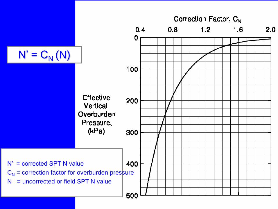
Figure 4.3 Chart for Correction of N-values in Sand for Influence of EffectiveOverburden Pressure (after Peck et al., 1974)
Figure 4.3 Chart for Correction of N-values in Sand for Influence of EffectiveOverburden Pressure (after Peck et al., 1974)
N’ = CN (N)
N’ = corrected SPT N value
CN = correction factor for overburden pressure
N = uncorrected or field SPT N value

TABLE 4-5 EMPIRICAL VALUES FOR , Dr, AND UNIT WEIGHT OF GRANULAR SOILS BASED ON
CORRECTED N' (after Bowles, 1977)
Description Very Loose Loose Medium Dense Very Dense
Relative density
Dr
0 - 0.15
0.15 - 0.35
0.35 - 0.65
0.65 - 0.85
0.85 - 1.00
Corrected
Standard
Penetration
N' value
0 to 4
4 to 10
10 to 30
30 to 50
50+
Approximate
angle of
internal
friction *
25 - 30˚
27 - 32˚
30 – 35˚
35 - 40˚
38 - 43˚
Approximate
range of moist
unit weight,
, kN/m3
(lb/ft3)
11.0 - 15.7
(70 - 100)
14.1 - 18.1
(90 - 115)
17.3 - 20.4
(110 - 130)
17.3 - 22.0
(110 - 140)
20.4 - 23.6
(130 - 150)
Correlations may be unreliable in soils containing gravel. See discussion in Section 9.5
of Chapter 9.
* Use larger values for granular material with 5% or less fine sand and silt.

TABLE 4-6 EMPIRICAL VALUES FOR UNCONFINED COMPRESSIVE STRENGTH (qu) AND CONSISTENCY OF COHESIVE SOILS BASED ON UNCORRECTED N
(after Bowles, 1977) Consistency Very Soft Soft Medium Stiff Very Stiff Hard
qu, kPa
(ksf)
0 – 24
(0 – 0.5)
24 – 48
(0.5 – 1.0)
48 – 96
(1.0 – 2.0)
96 – 192
(2.0 – 4.0)
192 – 384
(4.0 – 8.0)
384+
(8.0+)
Standard
Penetration
N value
0 - 2 2 - 4 4 – 8 8 - 16 16 - 32 32+
(saturated),
kN/m3
(lb/ft3)
15.8 - 18.8
(100 – 120)
15.8 - 18.8
(100 – 120)
17.3 - 20.4
(110 – 130)
18.8 - 22.0
(120 – 140)
18.8 - 22.0
(120 – 140)
18.8 - 22.0
(120 – 140)
The undrained shear strength is 1/2 of the unconfined compressive strength.
Note: Correlations are unreliable. Use for preliminary estimates only.

Undisturbed Samplers
• Thin wall open shelby tube
• Piston
• Hydraulic piston
• Pitcher
• Denison core barrel

Shelby Tube Samplers

Ground Water Monitoring
• Observation well
• Piezometer

Soil Profile Development
• Visual presentation of subsurface conditions
• Uncertainties in profile indicate need for
more borings & lab tests
• Develop in stages as data is available
• Identify soil layers, then lab test
determinations

Soil Profile Development
• Final soil profile includes:
– Soil physical properties (, qu, Cc, , etc.)
– Visual soil description
• Note ground water, boulders, voids, artesian
pressures, etc.
• Well developed soil profile is necessary to
design a cost effective foundation


IN-SITU TESTING
Reference Manual Chapter 5

In Situ Testing
• Provides design parameters in conditions
where high quality undisturbed samples
cannot be obtained
• In-situ tests are performed to obtain
foundation design parameters

Primary In-Situ Tests
• CPT – Cone Penetration Test
• CPTU – CPT with pore pressure measurement
• PMT – Pressuremeter Test
• DMT – Dilatometer Test
• VST – Vane Shear Test


Interpretation of CPT/CPTU Results
• Provides a continuous profile of subsurface
stratigraphy
• Soil classification from cone tip resistance &
friction ratio
• CPT correlations for evaluation of:
– Dr
–
– qu


A Series of Exploration Events
Setup at the Site

A Series of Exploration Events
Push the Cone

A Series of Exploration Events
Into the ground

A Series of Exploration Events
Induce a Shear Wave

A Series of Exploration Events
Interpret the Results

A Series of Exploration Events
Leave the Site

A Series of Exploration Events
Plug the hole from China

A Series of Exploration Events
Drive a Pipe

A Series of Exploration Events
It’s dark and the water flows

A Series of Exploration Events
We even used our pants

Advantages of CPT/CPTU
• Rapid & economic development of
continuous profile of subsurface conditions
• Determination of in situ strength parameters
• Reduce the number of conventional borings,
or focus attention on discrete zones for
sampling & testing

CPT/CPTU Disadvantages
• Cannot be pushed in dense soils
• CPT must be pushed in borehole advance
through dense deposits
• Soil samples not recovered
• Local correlations are important in data
interpretation

Pressuremeter and Dilatometer
• Limited applicability for vertically loaded
pile foundation design
• Pressuremeter useful for p-y curve
determination for lateral load designs
• Dilatometer has potential usefulness for
lateral load design


Vane Shear Testing
• In situ test to determine undrained shear
strength of soft to medium clays
• Measures peak & remolded strength
• Most accurate method for qu < 50 kPa (1 ksf)
• Very useful data for driveability analysis &
soil setup evaluation


LABORATORY TESTING
Reference Manual Chapter 6
Laboratory Testing
The trend to higher capacity piles & greater
pile penetration depths for special design
events reinforces the importance of accurate
determination of soil shear strength &
compressibility.
Laboratory Testing
• Quality of results far more important than
quantity of test results
• Inaccurate results may lead to design
misjudgements &/or construction problems

Laboratory Testing Cohesionless Soils:
SPT & CPT primary tools for and Dr,
complimented by index testing
Cohesive Soils:
Traditional tests on undisturbed samples yield best
results for qu and Cc

Lab QC Procedures • Sample handling & storage
• Sample prep
• Adherence to procedures
• Equipment calibration
• Qualification of personnel
• Result review & checking
• Reporting of test results


Types of Lab Tests
• Soil classification & index
• Shear strength
• Consolidation
• Electro chemical classification

Classification & Index Tests
• Moisture content
• Particle size analysis
• Atterberg limits
• Unit weight

Shear Strength Tests
• Unconfined compression
• Direct shear
• Triaxial compression

Consolidation Tests
• Amount of settlement
• Time rate of settlement

Electro Chemical Classification
• pH
• Resistivity
• Sulfate content
• Chloride content

Lab Tests for
Driveability Evaluations
• Remolded shear strength of cohesive soils
– Sensitivity St = qu-undist / qu-remold
( Sensitivity qualitative not quantitative indicator of soil setup )
• Gradation of cohesionless soils
– Fine content
– Angularity

Lesson 3 – Learning Outcomes
You will be able to:
• Explain what field & lab test results are needed
to develop a design soil profile for pile design.
• Identify SPT hammer types and their influence
on “N” values.
• Discuss the importance of quality subsurface
information & lab test results in pile design.

About the Site

USU Drainage Farm
• Infrastructure Engineering
• Earthquake Engineering
• Dynamic Testing
• Rehabilitation with
composite materials
• Wind Engineering
Pile Test Site

Any Questions

Recruiting Strategy • High School Bridge
Contest
– 10 to 19 schools
– Promotes USU and
Engineering
• Hospitality Tours
– Coordinate with
Math/Science Teachers
– Follow up letter
– 5 games, 16 HS, 500 +
students
• High School visits and
tutoring (Envir)

Purpose of the I-15 Testbed
• I-15 Corridor – Window
of opportunity
• Old Structures – a
destructive testing
opportunity
• New construction
– Behavior of soft clays
– Performance of innovative
structures
– Instrumentation

Sometimes we worked late

Sometimes it was overwhelming

There was always a bright side