substation maintenance tm 11-468 to 31w-1-102
TRANSCRIPT
DEPARTMENT OF THE ARMY TECHNICAL MANUAL
DEPARTMENT OF THE AIR FORCE TECHNICAL ORDER
SUBSTATIONMAINTENANCE
This copy is a reprint which includes currentpages from Changes 1 through 3.
DEPARTMENTS OF THE ARMY AND THE AIR FORCE
DECEMBER 1954
TM 11-468TO 31W-1-102

TM 11-468C3
Changes in force: C 2 and C 3
CHANGEHEADQUARTERS
No. 3 DEPARTMENT OF THE ARMYWASHINGTON, D.C. 11 December 1975
SUBSTATION MAINTENANCE
TM 11-468, 28 December 1954, TO 31W-1-102 is changed as follows:
Page 3, paragraph. 1.1 Delete paragraph 1.1 andsubstitute:
1.1. Indexes of Publicationsa. DA Pam 310-4. Refer to the latest issue of DA
Pam 310-4 to determine whether there are new editions,changes, or additional publications pertaining to theequipment.
b. DA Pam 310-7. Refer to DA Pam 310-7 todetermine whether there are modification work orders(MWO’s) pertaining to the equipment.Paragraph 2. Delete paragraph and substitute:
2. Maintenance Forms and Records
Maintenance forms, records, and reports which are to beused by maintenance personnel at all maintenancelevels are listed in and prescribed by TM 38-750.Paragraph 2.1 is added as follows.
2.1. Reporting of ErrorsThe reporting of errors, omissions, andrecommendations for improving this publication by theindividual user is encouraged. Reports should besubmitted on DA Form 2028 (Recommended Changesto Publications) and forwarded direct to Commander, USArmy Electronics Command, ATTN: AMSELMA-C, FortMonmouth, NY 07703.Page 106, appendix III. Delete appendix III.
}
1
TM 11-468
By Order of the Secretary of the Army:
CREIGHTON W. ABRAMSGeneral, United States Army
Official: Chief of StaffVERNE L.. BOWERS
Major General, United States ArmyThe Adjutant General
Distribution:Active Army:
USASA (2) Instl (2) exceptCNGB (1) Fort Gordon (10)ACSC-E (2) Fort Huachuca (10)Dir of Trans (1) Fort Carson (5)COE (1) Ft Richardson (ECOM Ofc) (2)TSG (1) WSMR (1)USAARENBD (1) Army Dep (2) exceptUSAMB (10) LBAD (14)AMC (1) SAAD (30)TRADOC (2) TOAD (14)ARADCOM (2) ATAD (10)ARADCOM Rgn (2) USA Dep (2)OS Maj Comd (4) Sig Sec USA Dep (2)LOGCOMDS (8) Sig Dep (2)MICOM (2) Sig FLDMS (1)TECOM (2) USAERDAA (1)USACC-CONUS (2) USAERDAW (1)USACC-EUR (2) MAAG (1)USACC-PAC (2) USARMIS (1)USACC-SO (2) Units org under fol TOE:USACC SIG GP-T (2) (1 copy each)USACC (4) 11-16MDW (1) 11-32Armies (2) 11-85Corps (2) 11-86HISA (ECOM) (21) 11-95Svc Colleges (1) 11-96USASESS (6) 11-97USAADS (2) 11-98USAFAS (2) 11-117USAARMS (2) 11-158USAIS (2) 11-302USAES (2) 11-337USAINTS (3) 11-500 (AA-AC)WRAMC (1) 29-134USACDCEC (10) 29-136ATS (1)
NG: NoneUSAR: None
For explanation of abbreviations used, see AR 310-60.
TM 11-468*C 2
Change In force: C 2
SUBSTATION MAINTENANCE
CHANGE HEADQUARTERSDEPARTMENT OF THE ARMY
No. 2 WASHINGTON, D.C., 21 September 1964
TM 11-468, 28 December 1954, is changed as follows:
Page 3. Add paragraph 1.1 after paragraph 1.
1.1. Index of PublicationsRefer to the latest issue of DA Pam 310-4 to
determine whether there are new editions, changes, oradditional publications pertaining to the equipment. DAPam 310-4 is an index. Of current technical manuals,technical bulletins, supply manuals (types 4, 6, 7, 8, and9), supply bulletins, lubrication orders, and modificationwork orders that are available through publicationssupply channels. The index lists the individual parts (-10,-20, -35, etc.) and the latest changes to and revisions ofeach equipment publications.
Paragraph 2 (as changed by C 1, 5 Dec 1960).Delete and substitute:
2. Forms and Recordsa. Reports of Maintenance and Unsatisfactory
Equipment. Use equipment forms and records inaccordance with instructions in TM1 38-750.
b. Report of Damaged or Improper Shipment. Fillout and forward DD Form 6 (Report of Damaged orImproper Shipment) as prescribed in AR 700-58 (Army),NAVSANDA Publication 378 (Navy), and AFR 71-4 (AirForce).
c. Reporting of Equipment Manual Improvements.The direct reporting, by the individual user, of errors,omissions, and recommendations for improving thismanual is authorized and encouraged. DA Form 2828(Recommended Changes to DA Publications) will beused for reporting these improvements. This form will becompleted in triplicate using pencil, pen, or typewriter.The original and one copy will be forwarded direct toCommanding General, U.S. Army Electronics Command,ATTN: AMSEIMR-MP-P, Fort Monmouth, N.J. 07703.One information copy will be furnished to the individual’simmediate super- visor (officer, noncommissionedofficer, super- visor, etc.).Page 106. Change Appendixes I and II (as added by C 1,5 Dec 60) to Appendixes II and III.Add Appendix I:
APPENDIX I
REFERENCES
DA Pam 310-4-Military Publications, Index 7, 8 and 9) Supply Bul-of Technical Manuals, letins, Lubrication Or-Technical Bulletins, Sup- ders, an d Modificationply Manuals (types 4, 6, Work Orders.
*· this change supersedes C 1, 5 December 1960
}
1
TM 11-468
TM 38-750 --Army Equipment Record Page 106. Delete Appendixes II and III andProcedures. substitute:
APPENDIX II
MAINTENANCE ALLOCATION
Section I. INTRODUCTION1. General
a. This section assigns maintenance functions tobe performed on components, assemblies, andsubassemblies by the lowest appropriate maintenancecategory.
b. Columns in the maintenance allocation chartare as follows:
(1) Part or component. This column showsonly the nomenclature or standard itemname. Additional descriptive data areincluded only where clarification isnecessary to identify the component.Components, assemblies, andsubassemblies are listed in top-downorder. That is, the assemblies which arepart of a component are listedimmediately below that component, andthe subassemblies which are part of anassembly are listed immediately belowthat assembly. Each generationbreakdown (components, assemblies, orsubassemblies) is listed in disassemblyorder or alphabetical order.
(2) Maintenance function. This columnindicates the various maintenancefunctions allocated to the categories.
(a) Service. To clean, to preserve, and toreplenish lubricants.
(b) Adjust. To regulate periodically toprevent malfunction.
(c) Inspect. To verify serviceability and todetect incipient electrical ormechanical failure by scrutiny. td)Test. To verify serviceability and todetect incipient electrical ormechanical failure by use of specialequipment such as gages, meters,etc.
(e) Replace. To substitute serviceablecomponents, assemblies, orsubassemblies, for serviceablecomponents, or subassemblies.
(f) Repair. To restore an item toserviceable condition through correctionof a specific failure or unservice- ablecondition. This function includes but is notlimited to welding, grinding, riveting,straightening, and replacement of partsother than the trial and error replacementof running spare type items such asfuses, lamps, or electron tubes.
(g) Align. To adjust two or more componentsof an electrical system so that theirfunctions are properly synchronized.
(h) Calibrate. To determine, check, or rectifythe graduation of an instrument, weapon,or weapons system, or components of aweapons system.
(i) Overhaul. To restore an item tocompletely serviceable condition asprescribed by serviceability standards.This is accomplished throughemployment of the technique of Inspectand Repair Only as Necessary (IROAN).Maximum utilization of diagnostic and testequipment is combined with minimumdisassembly of the item during theoverhaul process.
(j) Rebuild. To restore an item to a standardas near as possible to original or newcondition in appearance, performance,and life expectancy. This is accomplished
2
TM 11-468
through the maintenance techniqueof complete disassembly of theitem, inspection of all parts ofcomponents, repair or replacement ofworn or unserviceable elementsusing original manufacturingtolerances and/or specifications andsubsequent reassembly of the item.
(3) 1st, 2d, 3d, 4th, 5th echelons(operator, organization, directsupport, general support, and depot).The symbol X indicates thecategories responsible for performingthat particular maintenanceoperation, but does not necessarilyindicate that repair parts will bestocked at that level. Categorieshigher than those marked by X areauthorized to perform the indicatedoperation.
(4) Tools required. This column indicatescodes assigned to each individualtool equipment, test equipment, andmaintenance equipment referenced.The grouping of codes in this columnof the maintenance allocation chartindicates the tool, test, andmaintenance equipment required toperform the maintenance function.
(5) Remarks. Entries in this columnwill be utilized when necessary toclarify any of the data cited in thepreceding columns.
c. Columns in the allocation of tools formaintenance functions are as follows:
(1) Tools required for maintenancefunctions. This column lists tools,test, and maintenance equipmentrequired to perform the maintenancefunctions.
(2) 1st, 2d, 3d, 4th, 5th echelons(operator, organization, directsupport, general support, and depot).The dagger (t) symbol indicates thecategories normally allocated thefacility.
(3) Tool code. This column lists the toolcode assigned.
2. Maintenance by Using Organizations
When this equipment is used by signal servicesorganizations organic to theater head- quarters orcommunication zones to provide theatercommunications, those maintenance functions allocatedup to an including general support are authorized to theorganization operating this equipment.
3

TM 11-468Section II. MAINTENANCE ALLOCATION CHART
TELEPHONE SET TA-236/FT service X ExteriorX Interior
adjust X 4inspect Xtest X 1 continuity
X 1 All testingrepair X 4 All repairs except replacement of contact
assembly, foot mtg, handle handset, insulator plate, network, ringer telephone, rivet, shell, terminal board.
X 3,5overhaul X 1,2,3,5
PART OR COMPONENTMAINTENANCE
FUNCTIONDO/C O DS REMARKSTOOLS REQUIREDGS
4

TM 11-468Section III. ALLOCCATION OF TOOLS FOR MAINTENANCE FUNCTIONS
TA-236/FT (continued)
Multimeter TS-352/U t t t t 1
Test Set AN/PTM-6 t t 2
Tool Equipment TE-49 t t t 3 *When available use TS-716/U
Tool Equipment TE-23 t 4
Tool Equipment TE-111 t t t 5
TOOLS REQUIRED FOR MAINTENANCE FUNCTIONS DO/C O DS REMARKSTOOLSCODEGS
5
TM 11-468
APPENDIX III
BASIC ISSUE ITEM LIST
Section I. INTRODUCTION
1. GeneralThis appendix lists items supplied for initial
operation and for running spares. End items ofequipment are issued on the basis of allowancesprescribed in equipment authorization tables and otherdocuments that are a basis for requisitioning.
2. ColumnsColumns are as follows:a. Source, Maintenance, and Recoverability
Code. Not used.b. Federal Stock Number. This column lists the
11-digit Federal stock number.c. Designation by Model. Not used.
d. Description. Nomenclature or the standarditem name and brief identifying data for each item arelisted in this column. Whenrequisitioning, enter the nomenclature and description.
e. Unit of Issue. The unit of issue is each unlessotherwise indicated and is the supply term by which theindividual item is counted for procurement, storage,requisitioning, allowances, and issue purposes.
f. Expendability. Nonexpendable items areindicated by NX. Expendable items are not annotated.
g. Quantity Authorized. Under "Items Comprisingan Operable Equipment", the column lists the quantity ofitems supplied for the initial operation of the equipment.
h. IIlustrations. Not used.
6

TM 11-468SECTION II. FUNCTIONAL PARTS LIST
SOURCE ILLUSTRATIONMAINT. DESIGNATION UNIT QTY
AND FEDERAL BY DESCRIPTION OF EXPENDA-DIRECTRECOVER- STOCK NUMBER MODEL ISSUE BILITY UNIT FIG. ITEM
BILITY NO. NO.
ITEMS COMPRISING AN OPERABLE EQUIPMENT
TELEPHONE SET TA-236/FT
5806-503-2774 TELEPHONE SET TA-236 /FT ea. NX
Ord thru AGC TECHNICAL MANUAL TM 11-46R ea X 2
RUNNlNG SPARES AND ACCESSORY ITEM
TELEPHONE SET TA-236/FT
NO PARTS AUTHORIZED FOR STOCKAGE AT FIRST ECHELON
7
TM 11-468
By Order of the Secretary of the Army:
HAROLD K. JOHNSON,General, United States Army,
Official: Chief of StaffJ. C. LAMBERT,
Major General, United States Army,The Adjutant General.
Distribution: USACDC Agencies (1)Active Army: Blue Grass Army Dep (8)
CNGB (1) 11th Air Assault Div (3)CofT (1) US Army Tml (1) except Oakland (5)CofEngrs (1) POE (1)TSG (1) Sig Fld Maint Shops (3)CofSptS (1) USAERDL (2)C/COMMEL (7) USA Cold Rgns R&E Lab (2)USASA (2) Svc Colleges (2)USCONARC (5) Br Svc Sch (2) except USASCS (41J1USAMC (5) Army Dep (2) except Tobyhanna,ARADCOM (2) Lexington (12) Sacramento (28)ARADCOM Rgn (2) Ft Worth (8) Letterkenny, Navajo,OS Maj Comd (3) Savanna (5) Charleston, Sharpe (3)OS Base Comd (2) GENDEP (OS) (2)LOGCOMD (2) Sig Sec, GENDEP (OS) (6)USAMICOM (4) Sig Dep (OS) (12)USAECOM (32) USA Elct R&D Agcy:USA Avn Mat Comd (1) Yuma PG (2)USASCC (4) WSMR (13)*USASMCOM (2) Ft Gordon (5)USA Rsch Spt Gp (5) Ft Huachuca (10)USADCCEA, Ft Monmouth (1) USASESCS (40)MDW (1) USATCA (1)Armies (2) USATCG (1)Corps (2) USATCP (1)USA Corps (3) Units org under fol TOE (2 ea UNOINDC):Chicago Proc Dist (1) 11-16Instl (2) except 11-32
Ft Monmouth (63) 11-57USAINTC (5) 11-851st Fld Sta, USASA (5) 11-86USARSOUTHCOM Sig Agey (1) 11-95USAARMBD (2) 11-96USAARTYBD (2) 11-117USATC AD (2) 11-155USATC Armor (2) 11-157USATC Engr (2) 11-337USATC Inf (2) 11-500 AA-AE (4)USASTC (S) 11-557USA Pie Cen (2) 11-587WRAMC (1) 11-592AMS (1) 11-697
NG: NoneUSAR: None.For explanation of abbreviations used, see AR 320-50.
8

TM 11-468/TO 31W-1-102
This manual contains copyrighted material
TECHNICAL MANUAL DEPARTMENTS OF THE ARMY ANDNo. 11-468 THE AIR FORCE,TECHNICAL ORDER WASHINGTON 25, D. C., 28 December 1954No. 31W-1-102
SUBSTATION MAINTENANCE
CHAPTER 1. INTRODUCTION ..................................................................................................Paragraph PageSection I. General 1,2 3
II. Description and data..................................................................................................... 3--15 3--39CHAPTER 2. THEORY OF OPERATION
Section I. General ........................................................................................................................16, 17 40II. Telephone TPA............................................................................................................ 18-21 40--41III. Telephone Set TA-236/FT, component operation ...................................................... 22--26 42--16IV. Telephone Set TA-236/FT, circuit operation............................................................... 27--38 46--52
CHAPTER 3. MAINTENANCESection I. Tools and test equipment ............................................................................................39, 40 53--54
II. Preventive maintenance services................................................................................41, 42 54--58III. Lubrication ................................................................................................................... 43-45 58--60IV. Troubleshooting ........................................................................................................... 46-61 60--78
CHAPTER 4. REPAIR PROCEDURESSection I. Adjustments and tests ................................................................................................ 62--66 79--83
II. Contact maintenance.................................................................................................. 67--71 84, 85III. Repair and replacement of parts ................................................................................. 2--77 85--88IV. Final testing ................................................................................................................ 78--80 91, 92
CHAPTER 5. SHIPMENT AND LIMITED STORAGE AND DEMOLITION TO PREVENTENEMY USE........................................................................................................ 81-83 93
Index.................................................................................................................................................................. ............ 107
*This manual supersedes TM 11-48, 3 January 1 1952, including C 1, 22 December 1962.
}
1
TM 11-468
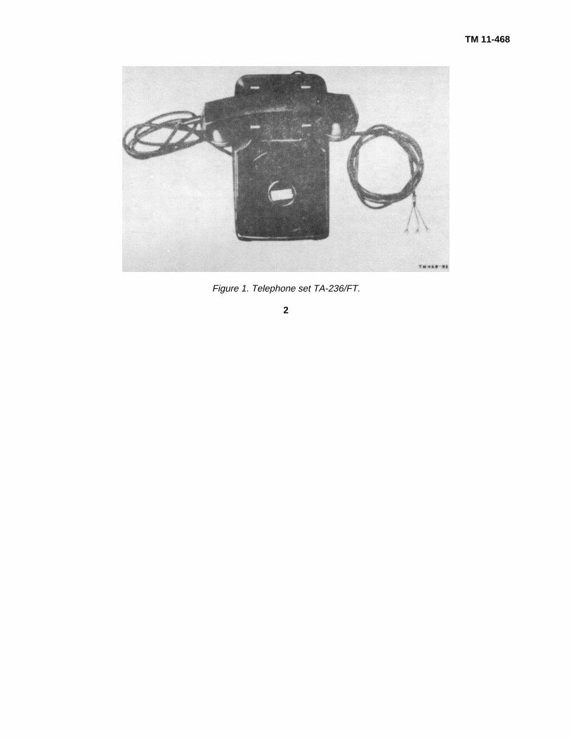
Figure 1. Telephone set TA-236/FT.
2

TM 11-468CHAPTER 1
INTRODUCTION
Section I. GENERAL
1. ScopeThis manual contains information on the theory of
operation, maintenance, and repair of telephonesubstation equipment.
2. FormsThe following forms will be used for reporting
unsatisfactory conditions of Army equipment and inperforming preventive maintenance:
a. DD Form 6, Report of Damaged or ImproperShipment, will be filled out and forwarded as prescribedin SR 745-45-5 (Army); Navy Shipping Guide, Article1850-4, (Navy), and AFR 71-4 (Air Force).
b. DA Form 468, Unsatisfactory EquipmentReport, will be filled out and forwarded to the Office ofthe Chief Signal Officer, as prescribed in SR 700-45-5.
c. DD Form 535, Unsatisfactory Report, will befilled out and forwarded as prescribed in SR 700-45-5and TO 00-35D-54.
d. DA Form 11-240, Operator First EchelonMaintenance Checklist for Signal Corps Equipment(Telephone Set), will be prepared in accordance withinstructions on the back of the form (par. 42).
e. DA Form 11-241, Second and Third EchelonMaintenance Checklist for Signal Corps Equipment(Telephone Set), will be prepared in accordance withinstructions on the back of the form (par. 42).f. Use other forms and records as authorized.
Section II. DESCRIPTION AND DATA
Note. Basic nomenclature followed by the symbol (*)is used to indicate all models of an item of equipmentcovered in this publication. For example, Dial TA- 45(*)/GT represents TA-45/GT and TA-45B/GT.
3. TP-6 Desk-Type Telephone Sets
a. Telephone TP- (figs. 2 through 15). TelephoneTP-6 represents seven models of desk-type telephonesets. These are cradle-type telephone sets that can beconverted from manual to dial operation by installing adial. They can be used with party-ringing or a metallicringing circuit and include an antisidetone circuit.
Although these equipments may be interchanged withone another in an existing telephone system, the partswith a few exceptions, are not interchangeable amongthe various models. Note that several of theseequipments that are classified as Telephone TP-6 haveindividual official nomenclature. It has been commonpractice in the past to refer to these telephone sets asTP-6 types; this practice is retained in this manual. Thetable below indicates the abbreviated form of thecommercial name, official nomenclature (if any), and thefigure references for each of the seven types.
Commercial name Abbreviated form Official nomenclature Fig. ref.
Western Electric Co. No. 302AW-3 ......... WECo No. 302AW-3 ......................... .............................................. 2 and 3.Automatic Electric Company No. 40........ Auto Elec No. 40 ............................... Telephone TA-101/FTC_ 4 and 5.Kellogg Switchboard & Supply Co. No. ... Kellogg No. 925BAX ......................... Telephone TA-102/FTC_ 6 and 7.
925BAX.Stromberg-Carlson Co. No. 1222BW...... St Carl No. 1222BW ......................... Telephone TA-113/FTC_ 8 and 9.North Electric Mfg. Co. No. 3H6SL* ........ North Elec Mfg No. 3H6SL................ 10 and 11.North Electric Mfg Co. No. H-600SL* ...... North Elece Mfg No. H-.................... 10 and 11.600SL.Stromberg-Carlson Co. No. 1242WA...... St Carl No. 1242WA ......................... 12 and 13.
*Although these telephone sets have different commercial names, there are only minor mechanical differences betweenthem. The parts, circuits, and color-codes are identical for both equipments.
3

TM 11-468
Figure 2. Telephone TP-6, arranged for manual operation
Figure 3. Telephone TP-6, with base plate open
4

TM 11-468
Figure 4. Telephone TA-101/FTC (Auto Elec No. 40), arranged for manual operation
Figure 5. Telephone TA-101/FTC (Auto Elec No. 40), with base plate open
5

TM 11-468
Figure 6. Telephone TA-102/FTC (Kellogg No. 925BAX), arranged for dial operation.
Figure 7. Telephone TA-102/FTC (Kellogg No. 925BAX), showing location of parts
6
TM 11-468
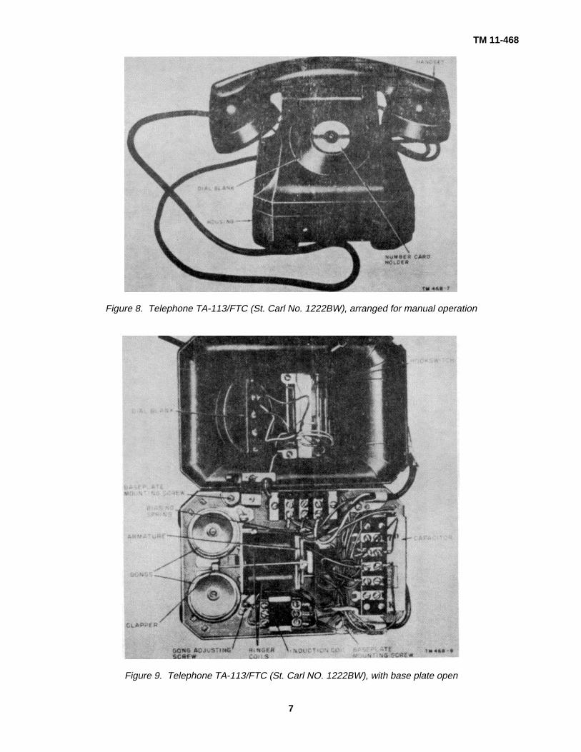
Figure 8. Telephone TA-113/FTC (St. Carl No. 1222BW), arranged for manual operation
Figure 9. Telephone TA-113/FTC (St. Carl NO. 1222BW), with base plate open
7

TM 11-468
Figure 10. Telephone TP-6 (North Elec Mfg No. H-600SL), arranged for dial operation
Figure 11. Telephone TP-6 (North Elec Mfg No. H-600SL and No. 3H6SL), with base plate open, showing locations ofparts
8

TM 11-468
Figure 12. Telephone TP-6 (St. Carl No. 1242WA), arranged for manual operation.
Figure 13. Telephone TP-6 (St. Carl No. 1242WA), showing location of parts
9
TM 11-468
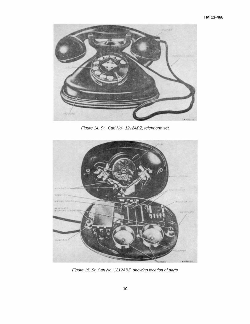
Figure 14. St. Carl No. 1212ABZ, telephone set.
Figure 15. St. Carl No. 1212ABZ, showing location of parts.
10
TM 11-468
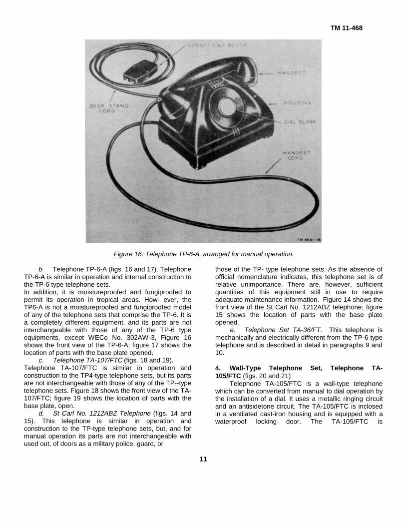
Figure 16. Telephone TP-6-A, arranged for manual operation.
b. Telephone TP-6-A (figs. 16 and 17). TelephoneTP-6-A is similar in operation and internal construction tothe TP-6 type telephone sets.In addition, it is moistureproofed and fungiproofed topermit its operation in tropical areas. How- ever, theTP6-A is not a moistureproofed and fungiproofed modelof any of the telephone sets that comprise the TP-6. It isa completely different equipment, and its parts are notinterchangeable with those of any of the TP-6 typeequipments, except WECo No. 302AW-3, Figure 16shows the front view of the TP-6-A; figure 17 shows thelocation of parts with the base plate opened.
c. Telephone TA-107/FTC (figs. 18 and 19).Telephone TA-107/FTC is similar in operation andconstruction to the TP4-type telephone sets, but its partsare not interchangeable with those of any of the TP--typetelephone sets. Figure 18 shows the front view of the TA-107/FTC; figure 19 shows the location of parts with thebase plate, open.
d. St Carl No. 1212ABZ Telephone (figs. 14 and15). This telephone is similar in operation andconstruction to the TP-type telephone sets, but, and formanual operation its parts are not interchangeable with
those of the TP- type telephone sets. As the absence ofofficial nomenclature indicates, this telephone set is ofrelative unimportance. There are, however, sufficientquantities of this equipment still in use to requireadequate maintenance information. Figure 14 shows thefront view of the St Carl No. 1212ABZ telephone; figure15 shows the location of parts with the base plateopened.
e. Telephone Set TA-36/FT. This telephone ismechanically and electrically different from the TP-6 typetelephone and is described in detail in paragraphs 9 and10.
4. Wall-Type Telephone Set, Telephone TA-105/FTC (figs. 20 and 21)
Telephone TA-105/FTC is a wall-type telephonewhich can be converted from manual to dial operation bythe installation of a dial. It uses a metallic ringing circuitand an antisidetone circuit. The TA-105/FTC is inclosedin a ventilated cast-iron housing and is equipped with awaterproof locking door. The TA-105/FTC is
used out, of doors as a military police, guard, or
11

TM 11-468
Figure 17. Telephone TP-6-A, with base plate open showing location of parts.
Figure 18. Telephone Set TA-107/FTC, arranged for dial operation
12
TM 11-468
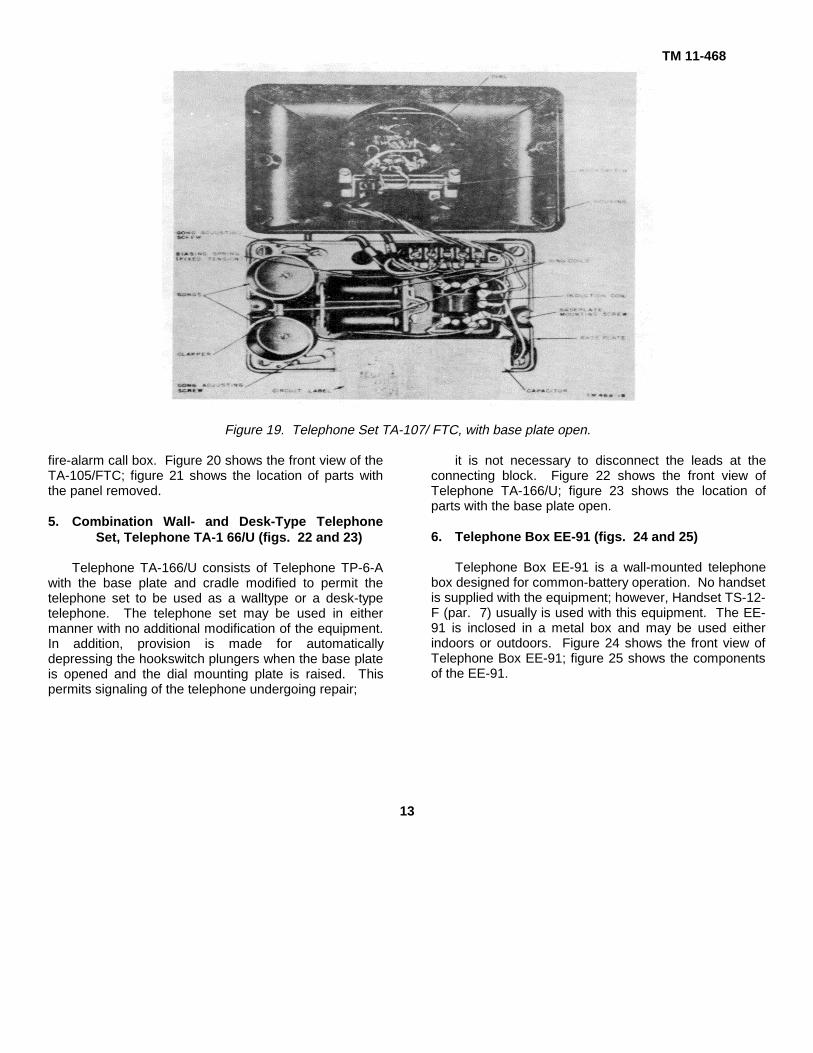
Figure 19. Telephone Set TA-107/ FTC, with base plate open.
fire-alarm call box. Figure 20 shows the front view of theTA-105/FTC; figure 21 shows the location of parts withthe panel removed.
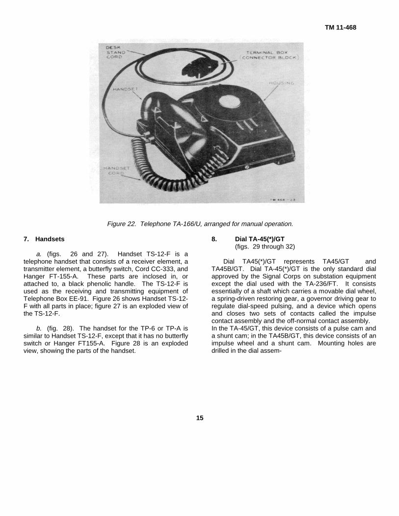
5. Combination Wall- and Desk-Type TelephoneSet, Telephone TA-1 66/U (figs. 22 and 23)
Telephone TA-166/U consists of Telephone TP-6-Awith the base plate and cradle modified to permit thetelephone set to be used as a walltype or a desk-typetelephone. The telephone set may be used in eithermanner with no additional modification of the equipment.In addition, provision is made for automaticallydepressing the hookswitch plungers when the base plateis opened and the dial mounting plate is raised. Thispermits signaling of the telephone undergoing repair;
it is not necessary to disconnect the leads at theconnecting block. Figure 22 shows the front view ofTelephone TA-166/U; figure 23 shows the location ofparts with the base plate open.
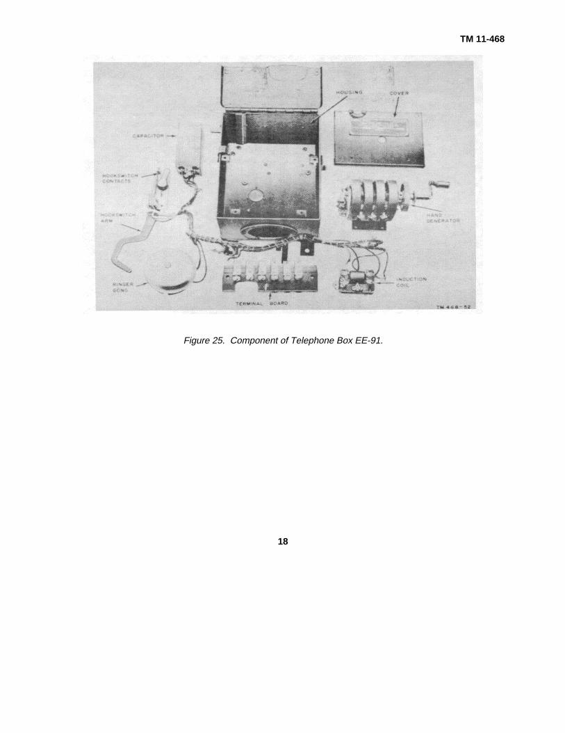
6. Telephone Box EE-91 (figs. 24 and 25)
Telephone Box EE-91 is a wall-mounted telephonebox designed for common-battery operation. No handsetis supplied with the equipment; however, Handset TS-12-F (par. 7) usually is used with this equipment. The EE-91 is inclosed in a metal box and may be used eitherindoors or outdoors. Figure 24 shows the front view ofTelephone Box EE-91; figure 25 shows the componentsof the EE-91.
13

TM 11-468
Figure 20. Telephone TA-105/FTC, guard and fire telephone.
Figure 21. Telephone TA-105/FTC, with panel removed, showing location of parts.
14
TM 11-468
Figure 22. Telephone TA-166/U, arranged for manual operation.
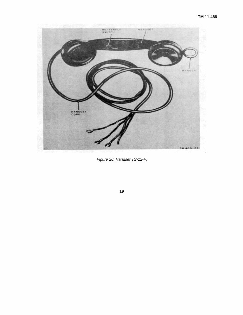
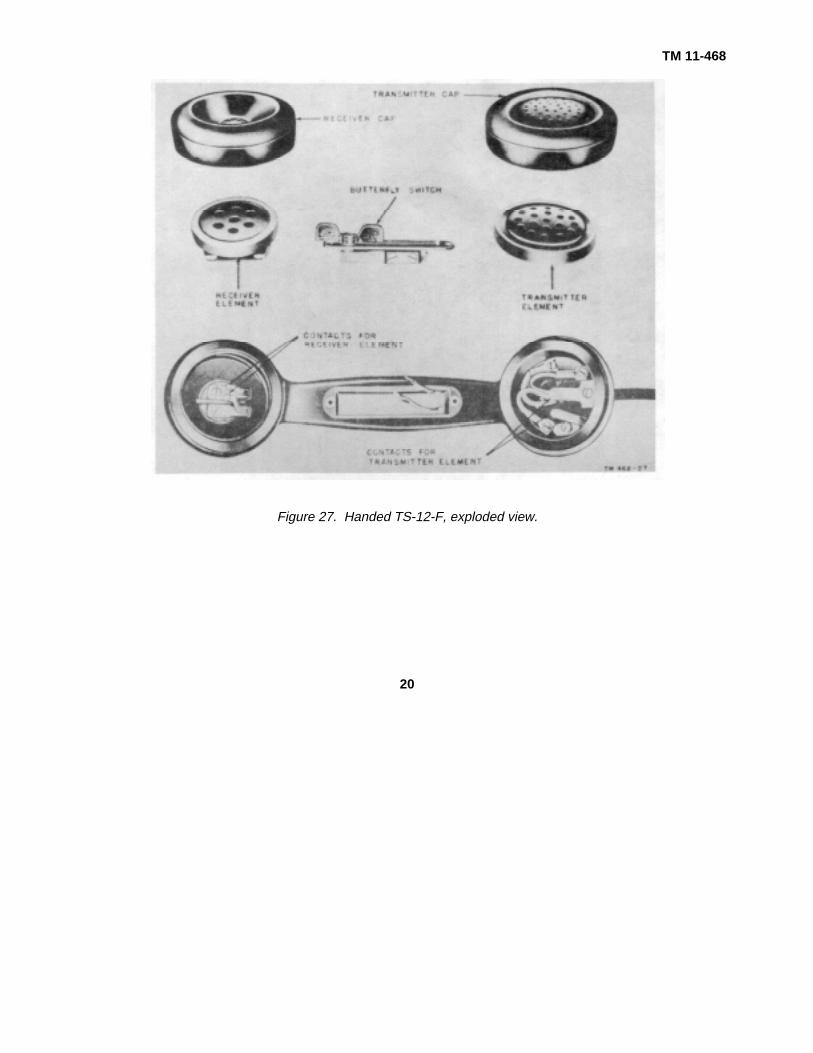
7. Handsets
a. (figs. 26 and 27). Handset TS-12-F is atelephone handset that consists of a receiver element, atransmitter element, a butterfly switch, Cord CC-333, andHanger FT-155-A. These parts are inclosed in, orattached to, a black phenolic handle. The TS-12-F isused as the receiving and transmitting equipment ofTelephone Box EE-91. Figure 26 shows Handset TS-12-F with all parts in place; figure 27 is an exploded view ofthe TS-12-F.
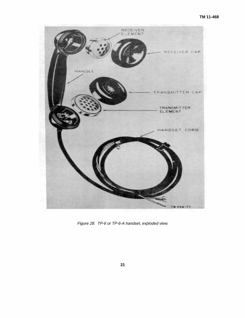
b. (fig. 28). The handset for the TP-6 or TP-A issimilar to Handset TS-12-F, except that it has no butterflyswitch or Hanger FT155-A. Figure 28 is an explodedview, showing the parts of the handset.
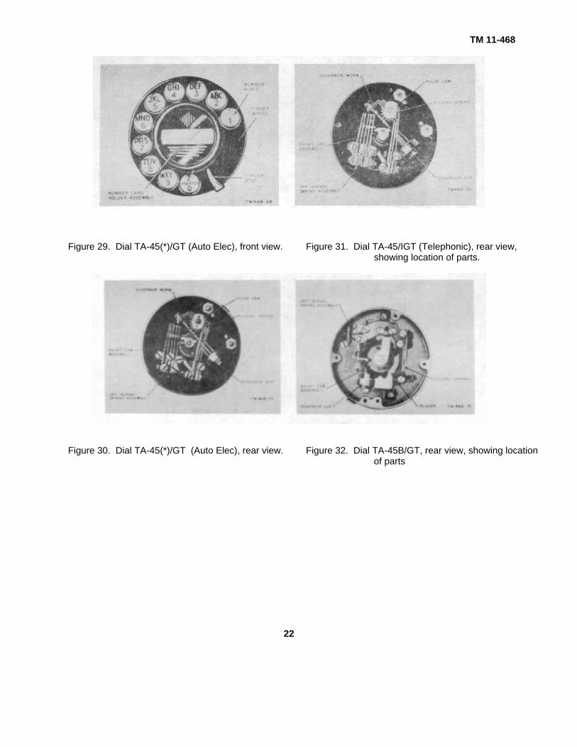
8. Dial TA-45(*)/GT(figs. 29 through 32)
Dial TA45(*)/GT represents TA45/GT andTA45B/GT. Dial TA-45(*)/GT is the only standard dialapproved by the Signal Corps on substation equipmentexcept the dial used with the TA-236/FT. It consistsessentially of a shaft which carries a movable dial wheel,a spring-driven restoring gear, a governor driving gear toregulate dial-speed pulsing, and a device which opensand closes two sets of contacts called the impulsecontact assembly and the off-normal contact assembly.In the TA-45/GT, this device consists of a pulse cam anda shunt cam; in the TA45B/GT, this device consists of animpulse wheel and a shunt cam. Mounting holes aredrilled in the dial assem-
15

TM 11-468
Figure 23. Telephone TA-1661U, with base plate open, showing location of parts.
bly to permit the mounting of the dial in any telephonethat is equipped to accept a dial. No dial adapter isrequired for any of the telephone sets described in thismanual except North Elec. Mfg telephone sets. Figure29 shows the front view of the TA-45(*)/GT. Figure 30shows the rear view of the TA-45(*)/GT manufactured bythe Automatic Electric Company; figure 31 shows therear view of the TA-45/GT manufactured by theTelephonic Corporation; figure 32 shows the rear view ofthe TA-45B/GT.
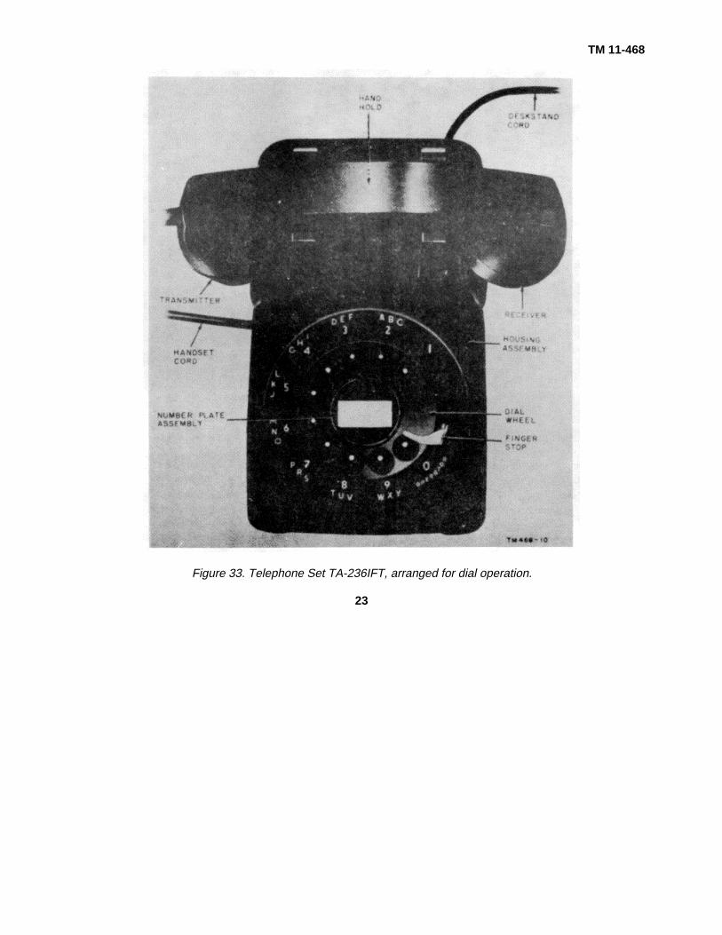
9. Telephone Set TA-236/FT, General (fig. 33)
Telephone Set TA-236/FT is a desk-type,antisidetone set that provides service in a commonbattery system that uses nonpolarized ringing current. Ingeneral outline, the TA-236/FT com
pares with Telephone TP-6 and similar-type telephonesets; however, none of the Telephone Set TA-236/FTparts are interchangeable with those of other types oftelephones. The set can be equipped to provide eitherdial or manual service. Wiring facilities are provided toadapt the set to the particular service required. Inaddition to the dial or dial blank, the set houses a ringer,capacitors, an induction coil, a hookswitch, a balancingnetwork, a three-conductor deskstand cord forconnecting the set to the line, and a four-conductorhandset cord for connecting the handset to the set. Anotched wheel in the base of the mounting assembly isused to adjust ringer loudness to any one of fourloudness levels. The line is terminated at a connectingblock near the set. The base of the set is about 1 inchlonger than that of the TP-6. A complete description ofindividual components is given in paragraph 10.
16

TM 11-468
Figure 24. Telephone Box EE-91, common-battery telephone.
17
TM 11-468
Figure 25. Component of Telephone Box EE-91.
18
TM 11-468
Figure 26. Handset TS-12-F.
19
TM 11-468
Figure 27. Handed TS-12-F, exploded view.
20
TM 11-468
Figure 28. TP-6 or TP-6-A handset, exploded view.
21
TM 11-468
Figure 29. Dial TA-45(*)/GT (Auto Elec), front view. Figure 31. Dial TA-45/IGT (Telephonic), rear view,showing location of parts.
Figure 30. Dial TA-45(*)/GT (Auto Elec), rear view. Figure 32. Dial TA-45B/GT, rear view, showing locationof parts
22
TM 11-468
Figure 33. Telephone Set TA-236IFT, arranged for dial operation.
23

TM 11-468
Figure 34. Telephone Set TA-236/FT, housing assembly
10. Component Description for Telephone Set TA-236/FT
a. Hosing Assembly (fig. 34). The housingassembly is made of a permanent black finishthermoplastic material; is fragile and must be handledcarefully.
b. Base Plate Assembly (fig. 35). The steel baseplate assembly is used for mounting the networkassembly, dial, ringer, and switch assembly. A dialmounting, equipped with three slots for theaccommodation of the dial mounting screws, is attachedpermanently to the base plate with three rivets. In asimilar manner, the network and switch assemblies areattached to the plate. A friction pad is riveted to eachcorner of the base plate. Two screws, captive in the baseplate, fasten the housing assembly to the base. In theupturned edge of the base plate are two smallrectangular slots; the slot in the end section is
used for anchoring the deskstand cord, and that in theside for anchoring the handset cord.
c. Handset (fig. 36). The handset is smaller and25 percent lighter in weight than those of the TP-6 type.The separation between the transmitter and the receiveris one-half inch less, which brings the transmitter closerto the speaker’s mouth when the receiver is placed at theear. The handset handle is of cored construction; thecord is a lightweight, flexible, neoprene jacketed type thatis held in place and reinforced by a tapered moldedgrommet at the handset end. The transmitter and thereceiver caps and elements are removable andreplaceable.
d. Transmitter (fig. 37). The transmitter issmaller, has an improved frequency response, betterstability characteristics, and greater efficiency than thetransmitter used with the TP-6 or TP-A.
24

TM 11-468
Figure 35. Telephone Set TA-236/FT, base plate assembly
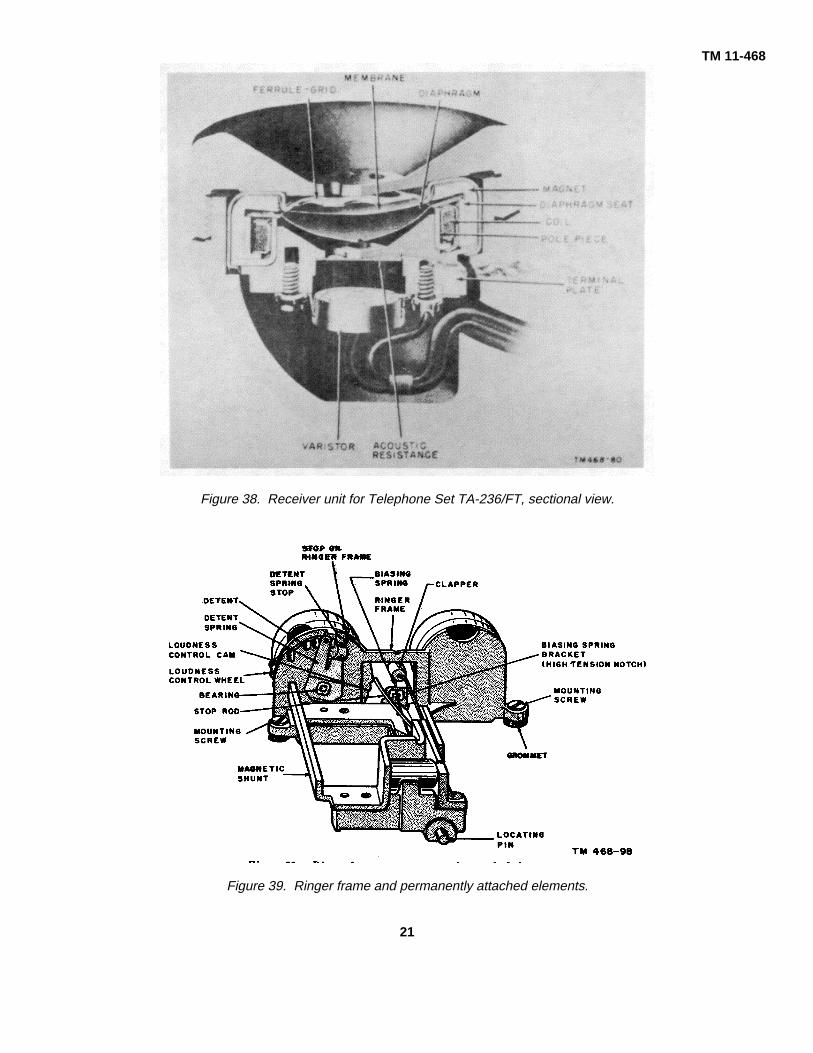
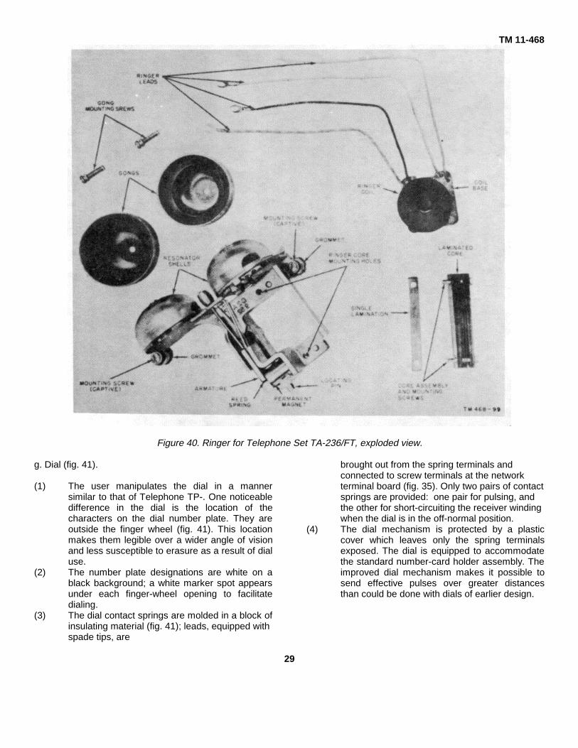
c. Receiver (fig. 38). The receiver has a domeddiaphragm of low mass and high effective area driven atthe circumference by a ring-shaped magnet. Thisreceiver is more efficient and has a greater frequencyrange than those of the TP-6 type telephones. Becauseof its higher efficiency and power capacity, a varistor isassembled as an integral part of the receiver.f. Ringer (figs. 39 and 40).
(1) The ringer components include a ringerframe, two ringer coils wound on asingle spool, a ringer coil core consistingof a cluster of 16 silicon steellaminations, two permanently mountedresonator shells, two brass gongs, abiasing spring, an armature stop rod,and a ringer loudness-controlarrangement.
(2) All parts of the ringer are attached to theringer frame (fig. 39). The loudness-control feature is accessible to the user
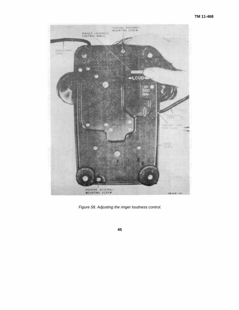
through the medium of a knurled section(control wheel) of the controlmechanism. The knurled sectionprojects through a rectangular slot in thebase plate. An arrow and the wordLOUD are stencilled on the base plateadjacent to the control wheel; the arrowbarb indicates the direction of controlrotation (fig. 58). The ringer provides alouder signal, when adjusted formaximum loudness, than any of theearlier types. Signal loudness can beselected at any one of four levels. Bythe application of a simple mechanicalmodification, a user controlled ringercutoff can be provided.
(3) Except for the ringer coil, coil core, andthe brass gongs, no part of the ringer isreplaceable at any maintenance level;however, the entire ringer can bereplaced. The procedures to follow in
25

TM 11-468
Figure 36. Handset for Telephone Set TA-236/FT, partially disassembled.
26

TM 11-468
Figure 37. Transmitter unit for Telephone Set TA-236/FT, sectional view.
completing a ringer replacement are discussed inparagraph 77d.(4) Biasing spring tension is determined by which of
two notches the spring rests in the biasing springbracket. One notch provides high tension, theother low tension.
(5) On a fully assembled ringer, one gong ismovable and the other is fixed. The fundamentalfrequency of vibration of the two gongs differs sothat the combination of fundamentals, overtones,and resonator effects produces a signal that ispleasing to the ear. The resonators cause anapproximate gain of 15 decibels in thefundamental frequencies of the gongs. The largelow frequency gain effectively increases theattracting qualities of the signal; also, it is helpfulto people whose hearing is impaired in thehigher frequency range.
(6) The ringer impedances are designed, withrespect to ringer and to voice frequencies, sothat up to five ringing bridges may be connectedto the line.
(7) Up to the point of ringer burnout, the ringer willnot suffer demagnetization in services from linesurges due to lightning or accidental contact withpower lines. The magnetic paths of theelectromagnet are proportioned so thatsaturation occurs long before the field strengthbecomes great enough to appreciably affect thepermanent magnet. A magnetic shunt is placedacross the core. In addition to its normal functionin the magnetic circuit, it serves also to increasethe coil impedance, and, in joining the two polepieces, adds mechanical strength to thestructure.
27
TM 11-468
Figure 38. Receiver unit for Telephone Set TA-236/FT, sectional view.
Figure 39. Ringer frame and permanently attached elements.
21
TM 11-468
Figure 40. Ringer for Telephone Set TA-236/FT, exploded view.
g. Dial (fig. 41).
(1) The user manipulates the dial in a mannersimilar to that of Telephone TP-. One noticeabledifference in the dial is the location of thecharacters on the dial number plate. They areoutside the finger wheel (fig. 41). This locationmakes them legible over a wider angle of visionand less susceptible to erasure as a result of dialuse.
(2) The number plate designations are white on ablack background; a white marker spot appearsunder each finger-wheel opening to facilitatedialing.
(3) The dial contact springs are molded in a block ofinsulating material (fig. 41); leads, equipped withspade tips, are
brought out from the spring terminals andconnected to screw terminals at the networkterminal board (fig. 35). Only two pairs of contactsprings are provided: one pair for pulsing, andthe other for short-circuiting the receiver windingwhen the dial is in the off-normal position.
(4) The dial mechanism is protected by a plasticcover which leaves only the spring terminalsexposed. The dial is equipped to accommodatethe standard number-card holder assembly. Theimproved dial mechanism makes it possible tosend effective pulses over greater distancesthan could be done with dials of earlier design.
29

TM 11-468
Figure 41. Dial for Telephone Set TA-236/FT, showing mechanism and housing.
30
TM 11-468
h. Network (fig. 35).
(1) The network assembly includes on induction coil,four capacitors, a dial radio interference filter,and an impedance balancing network. Theassembly is housed in a metal can. Anyremaining space in the can is filled with amoisture-proofing compound.
(2) The circuit components, within the network, arewired to a molded plastic terminal boardmounted in the top of the network can. Eachterminal designation is molded on the terminalboard surface adjacent to the associatedterminal. Molded projections on the terminalboard hold the set wires in place during solderingoperations. Molded stop studs and terminalsmounted at different surface levels preventaccidental contacts between cord tips andadjacent terminals. Other molded studs preventcord tips from backing out from under theterminal screws when screws are beingtightened.
(3) Network components are not accessible forinspection or maintenance purposes. Adefective network element requires replacementof the complete network assembly. The can actsas a shield to prevent cross talk when the talkingcircuit and the ringing circuit are connected todifferent lines. The can is riveted permanently tothe base plate. The capacitors used in thenetwork are newly-developed, metalized papercapacitors less than one-half the size of theconventional foil-paper capacitor of like capacity.These capacitors are self-healing in case ofdielectric failure caused by high voltage surges.
i. Switch (fig. 35).(1) The switch, with its protective plastic
housing removed, is shown in figure 35. Theswitch twin-contact springs are adjustedpermanently by the manufacturer. A notcheddetail, controlled by the hookswitch leverassembly, controls the movements of springs B,D, and G (fig. 67). A second notched detaillimits the travel distance of springs A, C, E, andF. Seven wire leads connect the switch contactsprings to associated terminals at the networkterminal board. Two of these leads are equippedwith spade tips; the remaining five leads aresoldered.
(2) Two machine screws attach the switch assemblyto the switch bracket. Three rivets attach theswitch bracket to the base plate. A removable,plastic housing is used to protect the switchassembly from foreign matter.
(3) A twin-armed switch control lever is pivoted tothe switch bracket, and a restoring spring issuspended between the bracket and the controllever.
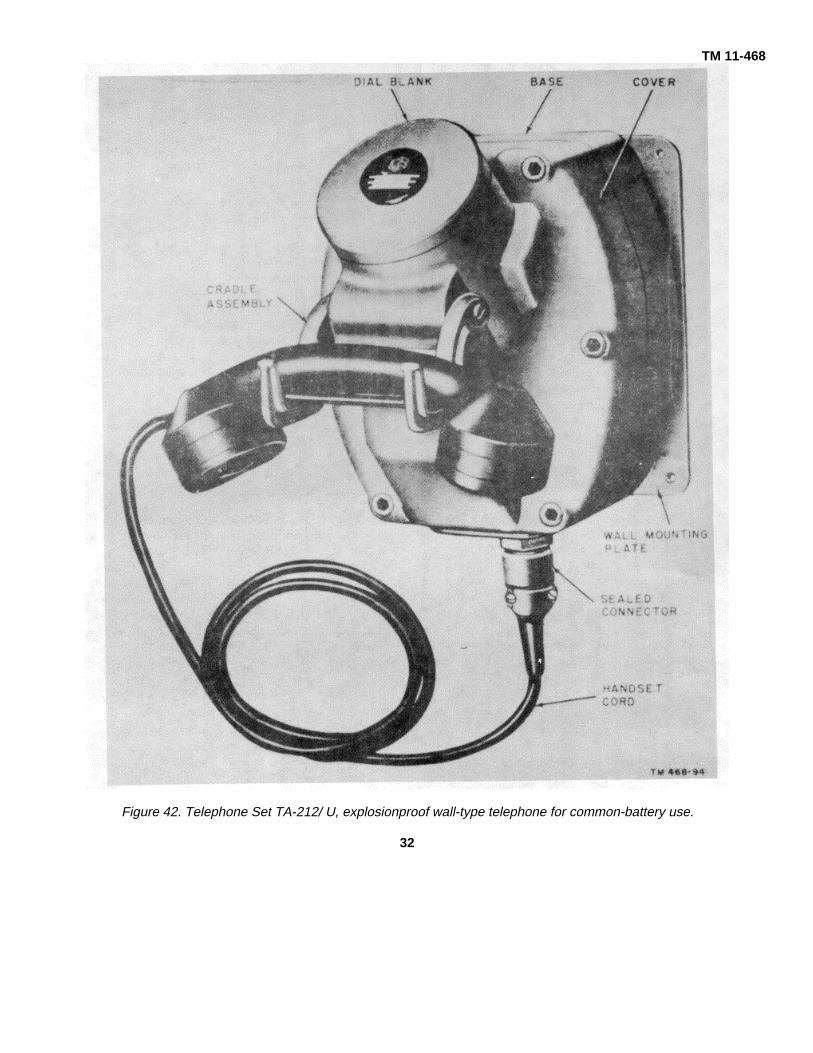
11. Telephone Set TA-21 2/U (figs. 42 and 43)Telephone Set TA-212/U is a common-battery,
wall-type telephone set that is used in an area exposedto combustible gas. The TA-212/U can be convertedfrom manual operation to dial operation by adding a dial.It is equipped with a standard handset. The circuitcomponents, excluding the handset, are inclosed in acast aluminum housing strong enough to withstand anexplosion inside the set. This prevents the flames fromigniting fumes or gas in the area outside the set. Allconnections to the set are sealed and the line wires areplaced in conduit which is attached to the set by meansof threaded openings and sealed.
31
TM 11-468
Figure 42. Telephone Set TA-212/ U, explosionproof wall-type telephone for common-battery use.
32

TM 11-468
Figure 43. Telephone Set TA-212/U, with cover open, showing location of parts.
12. Telephone Set TA-213/U(fig. 44)
Telephone Set TA-213/U is similar to the TA212/U(par. 11) except that it is used with a local batterysystem. The TA-213/U is equipped with Battery Box CY-1149 to provide an explosion proof compartment for thetransmission battery. A hand-ringing generator is alsocontained in the explosion proof housing to providesignaling current.
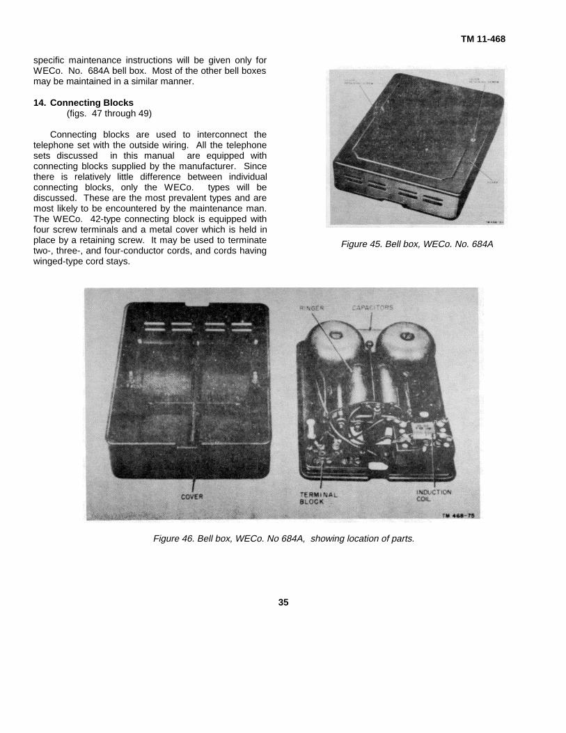
13. Bell Box, WECo. No. 684A (Antisidetone)(figs. 45 and 46)
This set contains an induction coil, a ringer, andcapacitors. It is not a complete telephone set; auxiliaryequipment consisting of a transmitter, a receiver, and ahookswitch is necessary to make up a completetelephone set. The bell box is wired in a manneridentical with the TP-6 type (WECo. No. 302AW-3)telephone. Although other bell boxes are in usethroughout the Signal Corps,
33

TM 11-468
Figure 44. Telephone Set TA-213/U, less Battery Box CY-1149.
34
TM 11-468
specific maintenance instructions will be given only forWECo. No. 684A bell box. Most of the other bell boxesmay be maintained in a similar manner.
14. Connecting Blocks(figs. 47 through 49)
Connecting blocks are used to interconnect thetelephone set with the outside wiring. All the telephonesets discussed in this manual are equipped withconnecting blocks supplied by the manufacturer. Sincethere is relatively little difference between individualconnecting blocks, only the WECo. types will bediscussed. These are the most prevalent types and aremost likely to be encountered by the maintenance man.The WECo. 42-type connecting block is equipped withfour screw terminals and a metal cover which is held inplace by a retaining screw. It may be used to terminatetwo-, three-, and four-conductor cords, and cords havingwinged-type cord stays.
Figure 45. Bell box, WECo. No. 684A
Figure 46. Bell box, WECo. No 684A, showing location of parts.
35

TM 11-468
Figure 47. WECo. 42-type connecting block.
Figure 48. WECo. 11-type connecting block.
Figure 49. WECo. 12-type connecting block.
36

TM 11-468
15. Protectors(figs. 50 through 53)
Protectors discussed in this manual are used toprotect telephone sets from the effects of lightning andother high-voltage surges that may accidentally becomepresent on telephone lines. All the protectors describedin this manual are equipped with carbon block spacecutouts and throw-away fuses.
a. There are two general types of protectors, theindoor and outdoor type. Protectors AR(Reliable ElectricCo. No. 1000) and AR-6-A (WECo. No. 1093A andCookeco No. 0-9) are designed for outdoor use. Forindoor use the cover of the WECo. 1093A protector isremoved and the protector is then called the WECo. No.98A protector. The WECo. No. 98A is the onlystandard protector designed for indoor use.
b. The protector blocks for Protector AR-6 (ReliableElectric Co. No. 1000) and the WECo. No. 98Aprotector consist of a solid carbon block and a porcelainblock with a carbon insert. The carbon insert isconnected electrically to one side of the line and thecarbon block is connected to ground. When installed onthe protector, the carbon block and the insert are spaced.003 inch apart, forming an air gap.
c. Protector AREA (Cook Electric Co. No. 0-9) isequipped with two solid carbon blocks separated by amica insert .003-inch thick, which forms an air gap. Oneof the blocks is connected to ground and the other isconnected to one side of the line.
d. Both types of open space cutouts (b and cabove) provide protection for the station against highvoltage, such as lightning and power lines. When thevoltage becomes too high on either side or both sides ofthe line, it will arc across the air gap to ground. If thevoltage is considerable or if the arc continues for aperiod of time, the carbon blocks will fuse togethercausing a permanent ground on either side or both sidesof the line.
Caution: Never change the air gap dimensions of theprotector blocks, because a change in the air gap willchange the operating limits of the protector block.
e. Protector fuses are used to protect the telephoneapparatus from a sustained abnormal current flow whichmay be established through the operation of the carbonblocks. These fuses are designed to operate on acurrent flow of 7 amperes or more.
Figure 50. Protector AR-8 (Reliable Electric Co. No.1000).
37

TM 11-468
Figure 51. Protector AR-6A (Cookeco. No. 0-9).
38

Figure 52. WECo. No. 98A protector, for inside installation.
Figure 53. Protector AREA (WECo. No. 1093A), for outside installation.
39

TM 11-468CHAPTER 2
THEORY OF OPERATION
Section I. GENERAL
16. TP- Type Telephones
The TP-6 type telephones are similar in circuitoperation to the TP-6-A, TA-166/U, TA-212/U, and theTA-105/FT. The circuit analysis of the TP-6-A ascovered in this chapter is typical and applicable withslight modification to all the TP-6 type telephones. Thecircuits and circuit components are fundamentally thesame; the chief difference is in the mechanicalconstruction of the parts and the color coding of thewiring. The components of these telephones areinterconnected to provide an antisidetone telephone asdescribed in TM 11478. The theory of the TP-6-A isdiscussed in detail in section II of this chapter.
17. Telephone Set TA-236/FT
The TA-236/FT is similar in appearance to the TP-6and the TP-6-A, but the circuits are electrically different,and the circuit components are mechanically different.The circuit components of TA-236/FT are a ringer,transmitter, receiver, and a network assembly. Thenetwork assembly contains the induction coil, fourcapacitors, three resistors, and two varistors, which arerequired for the transmission circuit. The circuits of theTA-236/FT are the ringer, transmitter, receiver, andantisidetone. The theory of operation of this telephone isdiscussed in detail in sections III and IV of this chapter.
Section II. TELEPHONE TP-6-A
18. General(fig. 54)
A simplified schematic diagram of a loop circuitshowing two telephones TP-6-A with the switchboardapparatus omitted from the diagram for simplicity isillustrated in figure 54. To simplify the circuit explanation,the circuit will be treated as if it were divided into threeseparate sections-the transmitting and receiving circuits,
the ringing circuit, and the antisidetone circuit.
19. Transmitting and Receiving Circuits
a. The basic parts of a transmitter are a diaphragm,a small carbon disk attached to the back of thediaphragm, and a small cup of carbon granules mountedbehind the diaphragm. The diaphragm vibrates at thesame rate as the sound waves directed against it. Asthe diaphragm
Figure 54. Loop circuit with two Telephones TP-6-A, schematic diagram.
40

TM 11-468
vibrates, the carbon disk varies the compactness of thecarbon granules in the cup which changes thetransmitter resistance. The transmitter is in series withthe line. Therefore, the direct current (de) in the primarycircuit and on the line will change to a fluctuating dc(voice current).
b. Battery is supplied to station A through the X andY windings of the retardation coil and to station B throughthe W and Z windings. The transmission path betweenstation A and station B is as follows: From thetransmitter of station A, through the BK and Y contacts ofthe hookswitch, L2 terminal, to capacitor T; fromcapacitor T to the L2 terminal of station B, through the Yand BK contacts of the hookswitch, through thetransmitter, to terminal R on the induction coil; fromterminal R on the induction coil through the primarywinding of the induction coil, L1 of station B to capacitorR; from capacitor R to L1 of station A, through theprimary winding of the induction coil, terminal R, andback to the transmitter at station A. The high impedanceof the ringer coils prevents shunting the voice currentsthrough the ringer circuit.
c. The receiver includes a combined permanentmagnet and electromagnet, and a diaphragm. As thevoice currents flow through the windings of theelectromagnet, a magnetic field, which alternately aidsand opposes the field of the permanent magnet, isestablished. The varying strength of the magnetic fieldcauses the receiver diaphragm to vibrate at the samerate as the diaphragm in the distant transmitter. Thisreproduces the sound picked up by the distanttransmitter.
d. The voice currents originating at station Aoperate the receiver at station B over the followingcircuit: voice currents flowing through the primarywinding of the induction coil at station B will induce avoltage in the secondary winding of the induction coil.The induced voltage will cause voice currents to flow tocapacitor C4; from capacitor C4 through the transmitter,receiver, W and GN contacts on the hookswitch, terminalGN on the induction coil, and back to the secondarywinding of the induction coil. The effect of the
balancing winding on the incoming voice currents isnegligible. The transmission for both telephones is thesame and these instructions apply equally to station Aand station B.
20. Ringing Circuit
The ringing circuit provides for signaling a telephonefrom a dial central office or from a manual switchboard.In both cases, 20 cycles per second (cps) alternatingcurrent (ac) is applied to terminals L1 and L2 of thecalled telephone. The ringer is in series with a capacitorand is permanently connected across terminals L1 andL2 to provide a path for ringing current. Ringing currentis blocked from the transmission circuit by the openhookswitch contacts. The capacitor prevents apermanent signal at the telephone central office byopening the ringing circuit to dc. The high impedance ofthe ringer coils to voice-frequency currents preventsvoice currents from being shunted through the ringingcircuit. Either side of the ringer may be grounded forparty-line service.
21. Antisidetone Circuit
Sidetone is the name given to the sound picked upby the transmitter and reproduced in the receiver of thesame telephone. When a telephone is used in a noisylocation, sidetone may be so loud that it is impossible tohear the incoming conversation. This effect must bereduced or eliminated. To reduce or eliminate sidetonewithout affecting the receiving circuit, a balancing(tertiary) winding with a noninductive resistance has beenadded to the induction coil. Voice currents produced bythe transmitter induce a voltage in the secondary windingand the balancing winding. If the circuit could beperfectly balanced the induced voltages would cancel,completely eliminating sidetone. However, a perfectbalance cannot be obtained under field conditions, so thesidetone is reduced instead of being completelyeliminated. The balancing winding is wound so that it haslittle or no effect on the incoming voice currents. For amore detailed explanation of antisidetone circuit theory,refer to TM 11-678
41

TM 11-468Section III. TELEPHONE SET TA-236/FT, COMPONENT OPERATION
22. Transmitter(fig. 37)
a. In general appearance and in some parts of itsstructural design, the transmitter resembles those thatare at present in use with Telephone TP-6 and similartypes of telephones. There have been several designchanges in addition to a special treatment of thetransmitter carbon grains that, in combination, provide adecided transmission improvement over transmitters ofdifferent design.
b. When in use, the transmitter is brought closer tothe speaker’s mouth. This desirable condition resultsfrom the newly designed handset handle.
c. The transmitter leads in the handset cordterminate at two terminals on a plastic cup located in thetransmitter element cavity at the handset handle Theplastic cup mounts two transmitter contact springs andacts as a partial receptacle for the transmitter element. Italso serves as a controlled acoustic (sound wave) cavityfor the transmitter and as an acoustic shield between thetransmitter and the receiver. Such a shield is necessary;otherwise, the transmitter and the receiver would becoupled acoustically.
23. Receiver(fig. 38)
a. The receiver differs radically in design from thatof other types of receivers. The simple diaphragm of theTP-6 type receiver is replaced by a ring armature, adome-shaped diaphragm of phenolic impregnated fabriccemented to a circular magnetic ring. The outer edge ofthe ring rests on a circular seat of nonmagnetic material.The inner edge is close to a circular pole piece whichconducts the magnetic flux from a ring-shapedpermanent magnet. This design lowers the mechanicalimpedance of the diaphragm and improves the radiationefficiency. As a result, when the receiver is held awayfrom the ear, the intelligibility of speech is much betterthan that of other receivers.
b. An acoustical network couples the backchamber of the diaphragm through four holes coveredwith acoustic resistance fabric to the handset cavity. Thechamber above the diaphragm exhausts through theholes in the receiver cap. The frequency response isvirtually flat from 400 to 3,500 cps.
c. A varistor protects the user from high acousticlevels caused by transient electrical disturbances
in the telephone circuit. This varistor also protects thereceiver magnet from demagnetization hazards of suchdisturbances.
24. Dial(fig. 41)
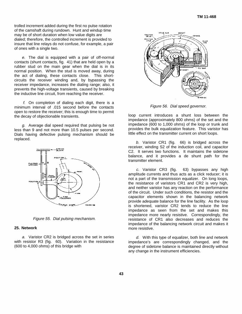
a. The dial pulsing mechanism (fig. 55) shows theoperating features of the dial. The pulsing ’ contacts areactuated by a single-lobed cam, mounted on a shaft, andgeared to a finger wheel in a ratio of 12 to 1. When thedial is in its at rest position, the cam is oriented so thatthe contacts, which are a part of the transmitter circuit,are held closed firmly. When the dial is wound up, aspring-controlled friction drive carries the pawl around torest against a stop (position 1, fig. 55).
b. During the first camshaft revolution, the cam liftsand lowers both springs A and B once for each rotationof the cam. However, because spring A is tensionedagainst spring B, the contacts remain closed and nopulses are formed during this revolution. At. the end ofthe windup, the springs are resting on the cam high dwell(broken lines, fig. 55). To increase the reliability of thepulsing contacts operations, springs A and B carry dualcontacts and spring A is split into two forks.
c. When the dial is released, it is returned to itsnormal position by the tensioned motor spring at a speedcontrolled by the governor (fig. 56). As > the dial runsdown, the cam first lowers and then lifts the springsduring its first revolution. During this interval, no pulseoccurs because the contacts in motion remain tensioned,one against the other. Also, during this revolution, thepawl finger travels clockwise to position 2 where itsupports spring A and prevents it from following spring Bduring the break portion of the cam cycle in the course ofthe second cam revolution. Thereafter, as spring Bcontinues to follow the cam, the contacts are opened andclosed once per cam revolution to produce pulses.Rundown stops with the springs resting on the cam highdwell and the contacts closed.
d. The time interval between successivesequences of pulses, corresponding to the digits of thedialed telephone number, is termed Interdigital lime.This time interval must be long enough to enable lineselecting relays to respond properly to separatesequences. Interdigital time is composed of hunt (thetime required by the user to locate the next digit to bedialed), windup, and the con
42
TM 11-468
trolled increment added during the first no pulse rotationof the camshaft during rundown. Hunt and windup timemay be of short duration when low value digits aredialed; therefore, the controlled increment is provided toinsure that line relays do not confuse, for example, a pairof ones with a single two.
e. The dial is equipped with a pair of off-normalcontacts (shunt contacts, fig. 41) that are held open by arubber stud on the main gear when the dial is in itsnormal position. When the stud is moved away, duringthe act of dialing, these contacts close. This short-circuits the receiver winding and, by bypassing thereceiver impedance, increases the dialing range; also, itprevents the high-voltage transients, caused by breakingthe inductive line circuit, from reaching the receiver.
f. On completion of dialing each digit, there is aminimum interval of .015 second before the contactsopen to restore the receiver; this is enough time to permitthe decay of objectionable transients.
g. Average dial speed required that pulsing be notless than 9 and not more than 10.5 pulses per second.Dials having defective pulsing mechanism should bereplaced.
Figure 55. Dial pulsing mechanism.
25. Network
a. Varistor CR2 is bridged across the set in serieswith resistor R3 (fig. 60). Variation in the resistance(600 to 4,000 ohms) of this bridge with
Figure 56. Dial speed governor.
loop current introduces a shunt loss between theimpedance (approximately 800 ohms) of the set and theimpedance (600 to 1,000 ohms) of the loop or trunk andprovides the bulk equalization feature. This varistor haslittle effect on the transmitter current on short loops.
b. Varistor CR1 (fig. 66) is bridged across thereceiver, winding S2 of the induction coil, and capacitorC2. It serves two functions. It maintains the sidetonebalance, and it provides a de shunt path for thetransmitter element.
c. Varistor CR3 (fig. 63) bypasses any highamplitude currents and thus acts as a click reducer; it isnot a part of the transmission equalizer. On long loops,the resistance of varistors CR1 and CR2 is very high,and neither varistor has any reaction on the performanceof the circuit. Under such conditions, the resistor and thecapacitor elements shown in the balancing networkprovide adequate balance for the line facility. As the loopis shortened, varistor CR2 tends to reduce the lineimpedance as seen from the set and makes thisimpedance more nearly resistive. Correspondingly, theresistance of CR1 also decreases and reduces theimpedance of the balancing network circuit and makes itmore resistive.
d. With this type of equalizer, both line and networkimpedance’s are correspondingly changed, and thedegree of sidetone balance is maintained directly withoutany change in the instrument efficiencies.
43

TM 11-468
e. The second function of varistor CR1 is that ofproviding a dc shunt path for the transmitter element. Onlong loops, this varistor has a very high resistance andhas no important reaction on the transmitter current. Asthe loops are shortened, the resistance of the varistordrops. On very short loops its resistance substantiallyapproaches that of the transmitter branch; therefore, itprovides a small transmission adjustment in the form ofbattery supply loss plus the protection feature of limitingthe current in the transmitter element.
f. Resistor R3, in conjunction with capacitor C3(fig. 66), acts as a filter to reduce radio interferencecaused by dialing. This combination acts also in theequalizing circuit.
g. The primary winding of the induction coil is splitwith one part (P1) connected into the ring side of the line,and the other part (P2) into the tip side of the line. Thisimproves circuit impedance balance.
26. Ringer(figs. 39 and 40)
a. A general description of the ringer used in theTA-236/PT is outlined in paragraph 10f. Figures 39 and40 show that it differs in design and construction fromringers normally in use. The only two degrees of ringerbias tension avail
able are high and low. Normally, the ringer is arrangedfor high tension bias. However, when three or morestations with ringers are bridged across a line, or wherethe loop is very long, the sensitivity is increased when thebiasing spring is positioned in the low tension notch atthe biasing ’ spring bracket.
b. When the ringer loudness control mechanism isset for maximum loudness, the ringer operates similar tothat of any other standard nonpolarized telephone setringer, but with a greater signal volume. Under thiscondition, the stop rod is free to operate through itsmaximum travel distance, and the maximum impactforce of the clapper is applied to the gongs. As theringer loudness control wheel is changed from theposition of maximum loudness into the next lowerloudness level, the detent spring leaves the maximumloudness detent in the ringer frame and moves into theadjacent detent. The loudness control cam is rotatedautomatically as the control wheel is rotated. Itssawtooth edge becomes positioned so that the stop-rodtravel distance is reduced, and the movable gong isbrought closer to the clapper.
c. This reduction of the stop-rod travel distancereduces the impact force of the clapper to the gongs.Thus the signal loudness is reduced.
Figure 57. Inverting the set to adjust ringer loudness control.
44
TM 11-468
Figure 58. Adjusting the ringer loudness control.
45

TM 11-468
d. Each change in position of the control wheelfrom maximum through two intermediate levels tominimum loudness causes a repetition of the changesoutlined in b and c above. As the control wheel positionchanges, a new surface in the sawtooth edge of the camis brought adjacent to the stop rod; each of these surfaceareas further reduces the stop-rod travel distance, andthe movable gong is moved nearer to the clapper.
e. Figure 57 shows how to prepare the set forloudness control adjustment while holding the handset inits cradle. Figure 58 shows the position of the set in thehands of the user at the time the adjustment is beingapplied.
f. Ringer cutoff can be provided when this featureis required. Cutoff may be permanent or it may be user-controlled. Permanent cutoff prevents the ringer fromoperating at any time. User-controlled cutoff may beapplied and removed at will by the user. The circuit andmechanical adjustments required in establishing theseservice features are explained further in paragraph 65b.
g. Figure 39 shows the biasing spring in the hightension biasing notch at the biasing spring bracket. Lowtension is obtained when the spring is moved to theadjacent notch.
Section IV. TELEPHONE SET TA-236/FT, CIRCUIT OPERATION
27. General
a. The individual circuits of the TA-236/FT arediscussed in paragraphs 28 through 38. Unlessotherwise noted, all terminals referred to in this sectionare at the network terminal board. The designations ofthe elements within the network, shown in the drawings,have been assigned arbitrarily for referenceidentification.
b. In paragraphs 29 through 37, the circuitdescription of each individual circuit of the Telephone SetTA-236/FT is outlined together with the continuity tracingof the wiring diagram of each circuit. The circuitdescription of the simplified schematic for each circuitmay be used for circuit tracing and study. The continuitytracing of each circuit may be used for troubleshootingand wiring each individual circuit in the telephone.
28. Ringer Circuit(fig. 59)
Ringing current from the ringing power sourcepasses over the ring side of the line to the connectingblock and through the YEL deskstand cord lead toterminal G. The current then passes through the BLKringer lead and the 1,000-ohm ringer coil winding and theGY ringer lead to terminal K. Ringing current leavesterminal K and flows through capacitor C4 to terminal A,through the GY-RED ringer lead, the 2,650-ohm ringercoil winding and the RED ringer lead to terminal L2,through the RED deskstand cord lead to the connectingblock, and the tip side of the line to the ringing powersource.
Figure 59. Ringer circuit, wiring.
29. Transmitter Circuit, Description(fig. 60)
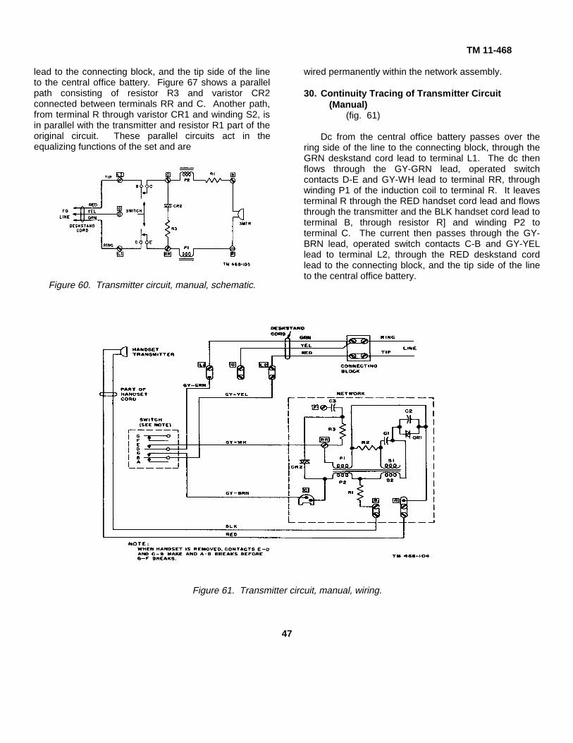
Dc from the central office battery passes over thering side of the line to the connecting block. It then flowsthrough the GRN deskstand cord lead to terminal L1,through operated hookswitch contacts D-E to terminalRR, through winding P1 of the induction coil to terminalR, through the transmitter to terminal B, through resistorR1 and winding P2 of the induction coil to terminal C,through operated switch contacts C-B to terminal L2,through the RED deskstand cord
46
TM 11-468
lead to the connecting block, and the tip side of the lineto the central office battery. Figure 67 shows a parallelpath consisting of resistor R3 and varistor CR2connected between terminals RR and C. Another path,from terminal R through varistor CR1 and winding S2, isin parallel with the transmitter and resistor R1 part of theoriginal circuit. These parallel circuits act in theequalizing functions of the set and are
Figure 60. Transmitter circuit, manual, schematic.
wired permanently within the network assembly.
30. Continuity Tracing of Transmitter Circuit(Manual)
(fig. 61)
Dc from the central office battery passes over thering side of the line to the connecting block, through theGRN deskstand cord lead to terminal L1. The dc thenflows through the GY-GRN lead, operated switchcontacts D-E and GY-WH lead to terminal RR, throughwinding P1 of the induction coil to terminal R. It leavesterminal R through the RED handset cord lead and flowsthrough the transmitter and the BLK handset cord lead toterminal B, through resistor R] and winding P2 toterminal C. The current then passes through the GY-BRN lead, operated switch contacts C-B and GY-YELlead to terminal L2, through the RED deskstand cordlead to the connecting block, and the tip side of the lineto the central office battery.
Figure 61. Transmitter circuit, manual, wiring.
47
TM 11-468
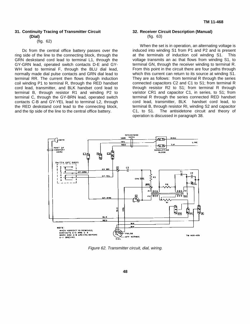
31. Continuity Tracing of Transmitter Circuit(Dial)
(fig. 62)
Dc from the central office battery passes over thering side of the line to the connecting block, through theGRN deskstand cord lead to terminal L1, through theGY-GRN lead, operated switch contacts D-E and GY-WH lead to terminal F, through the BLU dial lead,normally made dial pulse contacts and GRN dial lead toterminal RR. The current then flows through inductioncoil winding P1 to terminal R, through the RED handsetcord lead, transmitter, and BLK handset cord lead toterminal B, through resistor R1 and winding P2 toterminal C, through the GY-BRN lead, operated switchcontacts C-B and GY-YEL lead to terminal L2, throughthe RED deskstand cord lead to the connecting block,and the tip side of the line to the central office battery.
32. Receiver Circuit Description (Manual)(fig. 63)
When the set is in operation, an alternating voltage isinduced into winding S1 from P1 and P2 and is presentat the terminals of induction coil winding S1. Thisvoltage transmits an ac that flows from winding S1, toterminal GN, through the receiver winding to terminal R.From this point in the circuit there are four paths throughwhich this current can return to its source at winding S1.They are as follows: from terminal R through the seriesconnected capacitors C2 and C1 to S1; from terminal Rthrough resistor R2 to S1; from terminal R throughvaristor CR1 and capacitor C1, in series, to S1; fromterminal R through the series connected RED handsetcord lead, transmitter, BLK handset cord lead, toterminal B, through resistor RI, winding S2 and capacitorC1, to S1. The antisidetone circuit and theory ofoperation is discussed in paragraph 38.
Figure 62. Transmitter circuit, dial, wiring.
48
TM 11-468
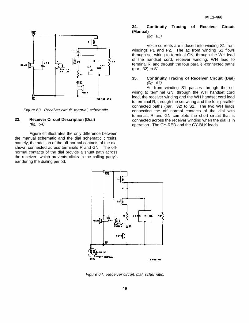
Figure 63. Receiver circuit, manual, schematic.
33. Receiver Circuit Description (Dial)(fig. 64)
Figure 64 illustrates the only difference betweenthe manual schematic and the dial schematic circuits,namely, the addition of the off-normal contacts of the dialshown connected across terminals R and GN. The off-normal contacts of the dial provide a shunt path acrossthe receiver which prevents clicks in the calling party’sear during the dialing period.
34. Continuity Tracing of Receiver Circuit(Manual)
(fig. 65)
Voice currents are induced into winding S1 fromwindings P1 and P2. The ac from winding S1 flowsthrough set wiring to terminal GN, through the WH leadof the handset cord, receiver winding, WH lead toterminal R, and through the four parallel-connected paths(par. 32) to S1.
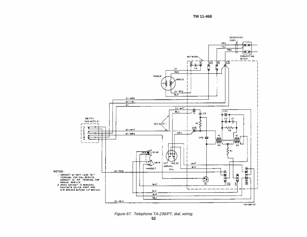
35. Continuity Tracing of Receiver Circuit (Dial)(fig. 67)Ac from winding S1 passes through the set
wiring to terminal GN, through the WH handset cordlead, the receiver winding and the WH handset cord leadto terminal R, through the set wiring and the four parallel-connected paths (par. 32) to S1. The two WH leadsconnecting the off normal contacts of the dial withterminals R and GN complete the short circuit that isconnected across the receiver winding when the dial is inoperation. The GY-RED and the GY-BLK leads
Figure 64. Receiver circuit, dial, schematic.
49

TM 11-468
Figure 65. Receiver circuit, manual, wiring.
connecting switch contacts F and G with terminals GNand R, respectively, complete the short circuit that isconnected across the receiver winding when thehookswitch is agitated (jiggled) to recall the operator tothe line. This circuit prevents annoying clicks at thereceiver during recall periods.
36. Dialing Circuit Description(fig. 66)
Dialing current from the central office battery passesover the ring side of the line to the connecting block,through the GRN deskstand cord lead to terminal LJ1,through the operated switch contacts D-E to terminal F,through the normally made dial pulsing contacts toterminal RR. From terminal RR the current passes overthree parallel-connected paths to terminal C, throughoperated switch contacts C-B to terminal 1,2, through theRED deskstand cord lead to the connecting block, andthe tip side of the line to the central office battery. Thethree parallel paths, referred to above, are as follows:
from terminal RR through series-connected resistor R3and varistor CR2 to terminal C; from terminal RR throughseries-connected winding P1 varistor CR1, windings S2and P2 to terminal C; the series-connected transmitterand resistor R1 are connected in parallel with varistorCR1 and winding S2.
37. Continuity Tracing of Dialing Circuit(fig. 67)
Dialing current, from the central office battery passesover the ring side of the line to the connecting block,through the GRN deskstand cord lead to terminal L1,through the GY-GRN switch lead, operated switchcontacts D-E and GY-WH lead to terminal F, through theBLU dial lead, normally made dial pulse contacts, andGRN dial lead to terminal RR. From terminal RR thecurrent passes over three parallel-connected paths toterminal C (par. 36), through the GY-BRN lead, operatedswitch contacts C-B, and GY-YEL
50

TM 11-468
Figure 66. Dialing circuit, schematic.
lead to terminal L2, through the RED deskstand cordlead to the connecting block, and the tip side of the lineto the central office battery.
38. Antisidetone
a. Figures 61 and 62 show the transmitter circuit.Figures 65 and 67 show the receiver circuit.
The drawings show the balancing network associatedwith both circuits.
b. The speech currents received from the line, inpassing through windings P1, P2, and S2, induceadditive voltages in winding S1, which is connected tothe receiver winding.
c. These additive voltages tend to cause currentsto flow in resistor R2. However, these currents, inpassing through winding S2, induce a voltage that is1800 out of phase and approximately equal in amplitudeto the voltages induced by windings P1 and P2. Theresultant voltage across resistor R2, therefore, is verysmall. Maximum useful receiving currents thus areobtained without appreciable power loss in the networkresistance.
d. When the local transmitter is in operation, avoltage drop is developed across its terminals. Thisvoltage acts on windings P1 and P2. It also acts acrosswinding S2 which, in this instance, is parallel-connectedwith windings P1 and P2. The currents resulting fromthese voltages cause voltages to be induced in windingS1. The voltages induced in S1, as a result of thecurrents flowing in P1 and P2, are substantially equaland opposite to the voltage induced as a result of thecurrents flowing in S2. Also, part of the currents flowingout of S2 pass through resistor R2. These currentsdevelop a voltage drop across resistor R2, which isphased to oppose the resultant voltage at winding S1.
e. The overall effect of this balance is that thecurrents in the receiver winding, as a result of the voltagedeveloped across the transmitter, are small. This resultsin higher transmitting levels, because there is little powerloss in the receiver circuit.
j. Sidetone balance will not be equal under alltransmission conditions, because loop impedances varygreatly in magnitude and phase for different plantconditions.
51
TM 11-468
Figure 67. Telephone TA-236/PT, dial, wiring.52
TM 11-468CHAPTER 3
MAINTENANCE
Section I. TOOLS AND TEST EQUIPMENT
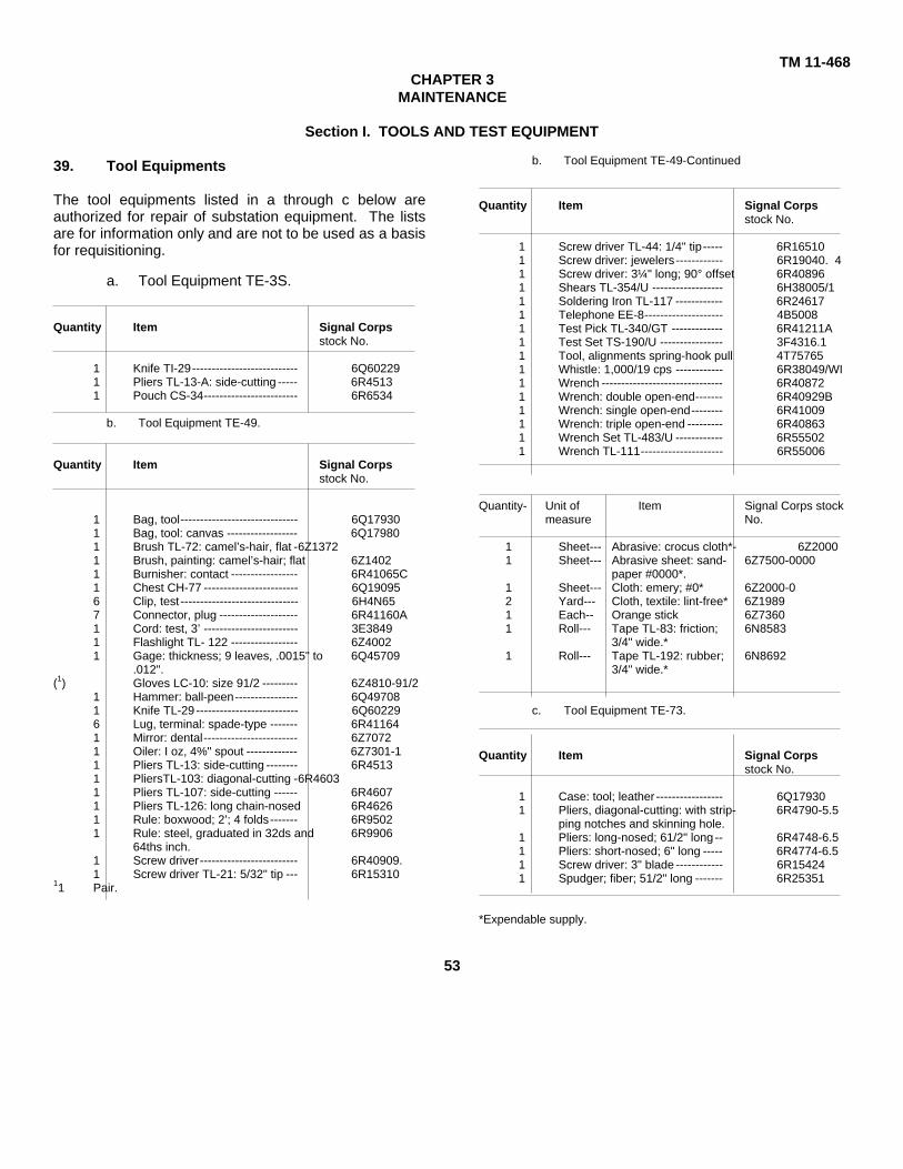
39. Tool Equipments
The tool equipments listed in a through c below areauthorized for repair of substation equipment. The listsare for information only and are not to be used as a basisfor requisitioning.
a. Tool Equipment TE-3S.
Quantity Item Signal Corpsstock No.
1 Knife TI-29--------------------------- 6Q602291 Pliers TL-13-A: side-cutting ----- 6R45131 Pouch CS-34------------------------ 6R6534
b. Tool Equipment TE-49.
Quantity Item Signal Corpsstock No.
1 Bag, tool------------------------------ 6Q179301 Bag, tool: canvas ------------------ 6Q179801 Brush TL-72: camel’s-hair, flat -6Z13721 Brush, painting: camel’s-hair; flat 6Z14021 Burnisher: contact ----------------- 6R41065C1 Chest CH-77 ------------------------ 6Q190956 Clip, test ------------------------------ 6H4N657 Connector, plug -------------------- 6R41160A1 Cord: test, 3’ ------------------------ 3E38491 Flashlight TL- 122 ----------------- 6Z40021 Gage: thickness; 9 leaves, .0015" to 6Q45709
.012".(1) Gloves LC-10: size 91/2 --------- 6Z4810-91/2
1 Hammer: ball-peen---------------- 6Q497081 Knife TL-29 -------------------------- 6Q602296 Lug, terminal: spade-type ------- 6R411641 Mirror: dental------------------------ 6Z70721 Oiler: I oz, 4%" spout ------------- 6Z7301-11 Pliers TL-13: side-cutting -------- 6R45131 PliersTL-103: diagonal-cutting -6R46031 Pliers TL-107: side-cutting ------ 6R46071 Pliers TL-126: long chain-nosed 6R46261 Rule: boxwood; 2’; 4 folds------- 6R95021 Rule: steel, graduated in 32ds and 6R9906
64ths inch.1 Screw driver------------------------- 6R40909.1 Screw driver TL-21: 5/32" tip --- 6R15310
11 Pair.
b. Tool Equipment TE-49-Continued
Quantity Item Signal Corpsstock No.
1 Screw driver TL-44: 1/4" tip----- 6R165101 Screw driver: jewelers------------ 6R19040. 41 Screw driver: 3¼" long; 90° offset 6R408961 Shears TL-354/U ------------------ 6H38005/11 Soldering Iron TL-117 ------------ 6R246171 Telephone EE-8-------------------- 4B50081 Test Pick TL-340/GT ------------- 6R41211A1 Test Set TS-190/U ---------------- 3F4316.11 Tool, alignments spring-hook pull 4T757651 Whistle: 1,000/19 cps ------------ 6R38049/WI1 Wrench ------------------------------- 6R408721 Wrench: double open-end------- 6R40929B1 Wrench: single open-end-------- 6R410091 Wrench: triple open-end --------- 6R408631 Wrench Set TL-483/U ------------ 6R555021 Wrench TL-111--------------------- 6R55006
Quantity- Unit of Item Signal Corps stockmeasure No.
1 Sheet--- Abrasive: crocus cloth*- 6Z20001 Sheet--- Abrasive sheet: sand- 6Z7500-0000
paper #0000*.1 Sheet--- Cloth: emery; #0* 6Z2000-02 Yard--- Cloth, textile: lint-free* 6Z19891 Each-- Orange stick 6Z73601 Roll--- Tape TL-83: friction; 6N8583
3/4" wide.*1 Roll--- Tape TL-192: rubber; 6N8692
3/4" wide.*
c. Tool Equipment TE-73.
Quantity Item Signal Corpsstock No.
1 Case: tool; leather ----------------- 6Q179301 Pliers, diagonal-cutting: with strip- 6R4790-5.5
ping notches and skinning hole.1 Pliers: long-nosed; 61/2" long -- 6R4748-6.51 Pliers: short-nosed; 6" long ----- 6R4774-6.51 Screw driver: 3" blade ------------ 6R154241 Spudger; fiber; 51/2" long ------- 6R25351
*Expendable supply.
53
TM 11-468
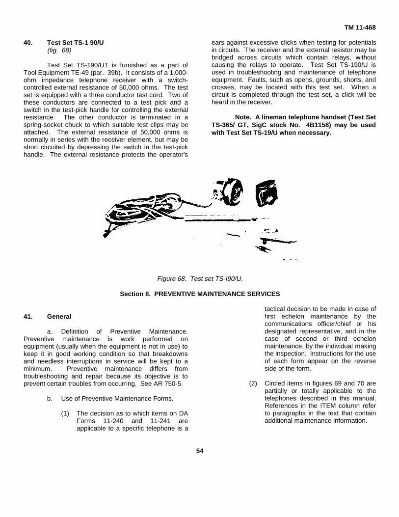
40. Test Set TS-1 90/U(fig. 68)
Test Set TS-190/UT is furnished as a part ofTool Equipment TE-49 (par. 39b). It consists of a 1,000-ohm impedance telephone receiver with a switch-controlled external resistance of 50,000 ohms. The testset is equipped with a three conductor test cord. Two ofthese conductors are connected to a test pick and aswitch in the test-pick handle for controlling the externalresistance. The other conductor is terminated in aspring-socket chuck to which suitable test clips may beattached. The external resistance of 50,000 ohms isnormally in series with the receiver element, but may beshort circuited by depressing the switch in the test-pickhandle. The external resistance protects the operator’s
ears against excessive clicks when testing for potentialsin circuits. The receiver and the external resistor may bebridged across circuits which contain relays, withoutcausing the relays to operate. Test Set TS-190/U isused in troubleshooting and maintenance of telephoneequipment. Faults, such as opens, grounds, shorts, andcrosses, may be located with this test set. When acircuit is completed through the test set, a click will beheard in the receiver.
Note. A lineman telephone handset (Test SetTS-365/ GT, SigC stock No. 4B1158) may be usedwith Test Set TS-19/U when necessary.
Figure 68. Test set TS-I90/U.
Section II. PREVENTIVE MAINTENANCE SERVICES
41. General
a. Definition of Preventive Maintenance.Preventive maintenance is work performed onequipment (usually when the equipment is not in use) tokeep it in good working condition so that breakdownsand needless interruptions in service will be kept to aminimum. Preventive maintenance differs fromtroubleshooting and repair because its objective is toprevent certain troubles from occurring. See AR 750-5.
b. Use of Preventive Maintenance Forms.
(1) The decision as to which items on DAForms 11-240 and 11-241 areapplicable to a specific telephone is a
tactical decision to be made in case offirst echelon maintenance by thecommunications officer/chief or hisdesignated representative, and in thecase of second or third echelonmaintenance, by the individual makingthe inspection. Instructions for the useof each form appear on the reverseside of the form.
(2) Circled items in figures 69 and 70 arepartially or totally applicable to thetelephones described in this manual.References in the ITEM column referto paragraphs in the text that containadditional maintenance information.
54
TM 11-468
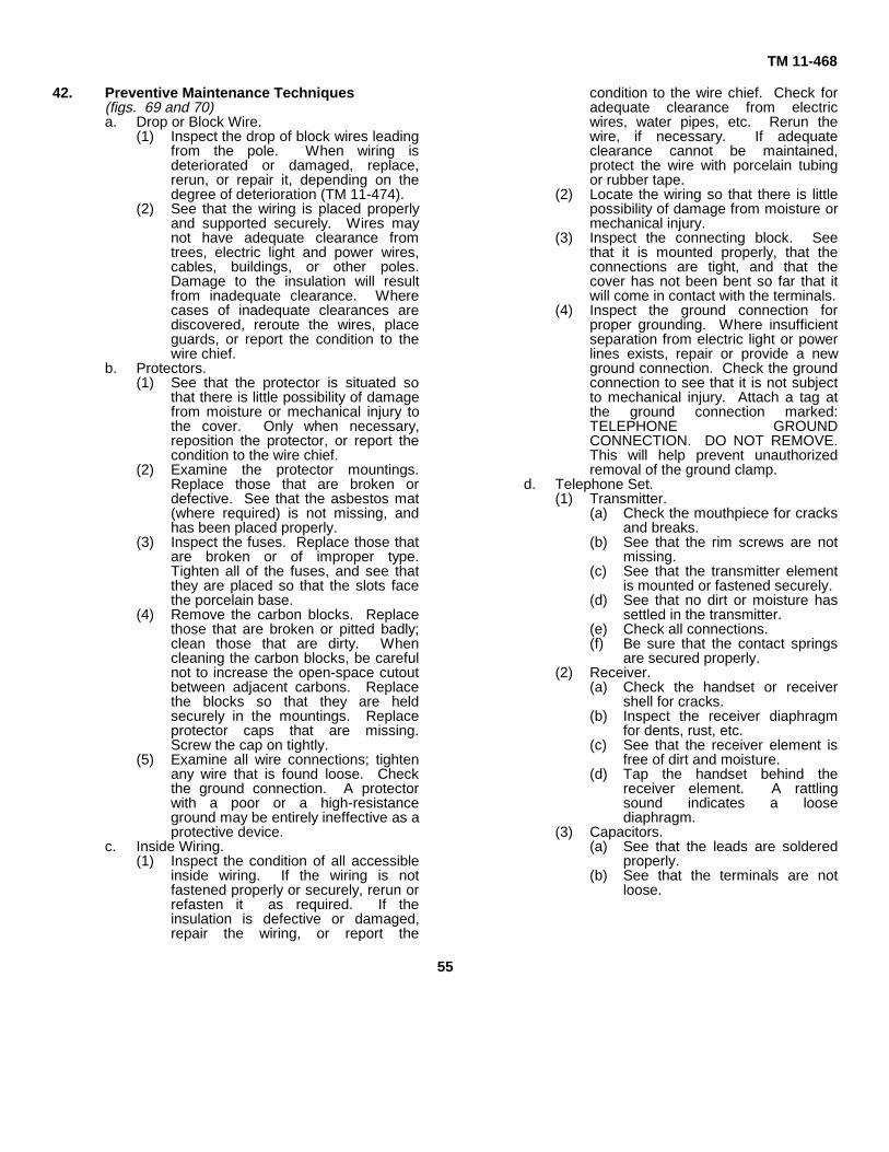
42. Preventive Maintenance Techniques(figs. 69 and 70)a. Drop or Block Wire.
(1) Inspect the drop of block wires leadingfrom the pole. When wiring isdeteriorated or damaged, replace,rerun, or repair it, depending on thedegree of deterioration (TM 11-474).
(2) See that the wiring is placed properlyand supported securely. Wires maynot have adequate clearance fromtrees, electric light and power wires,cables, buildings, or other poles.Damage to the insulation will resultfrom inadequate clearance. Wherecases of inadequate clearances arediscovered, reroute the wires, placeguards, or report the condition to thewire chief.
b. Protectors.(1) See that the protector is situated so
that there is little possibility of damagefrom moisture or mechanical injury tothe cover. Only when necessary,reposition the protector, or report thecondition to the wire chief.
(2) Examine the protector mountings.Replace those that are broken ordefective. See that the asbestos mat(where required) is not missing, andhas been placed properly.
(3) Inspect the fuses. Replace those thatare broken or of improper type.Tighten all of the fuses, and see thatthey are placed so that the slots facethe porcelain base.
(4) Remove the carbon blocks. Replacethose that are broken or pitted badly;clean those that are dirty. Whencleaning the carbon blocks, be carefulnot to increase the open-space cutoutbetween adjacent carbons. Replacethe blocks so that they are heldsecurely in the mountings. Replaceprotector caps that are missing.Screw the cap on tightly.
(5) Examine all wire connections; tightenany wire that is found loose. Checkthe ground connection. A protectorwith a poor or a high-resistanceground may be entirely ineffective as aprotective device.
c. Inside Wiring.(1) Inspect the condition of all accessible
inside wiring. If the wiring is notfastened properly or securely, rerun orrefasten it as required. If theinsulation is defective or damaged,repair the wiring, or report the
condition to the wire chief. Check foradequate clearance from electricwires, water pipes, etc. Rerun thewire, if necessary. If adequateclearance cannot be maintained,protect the wire with porcelain tubingor rubber tape.
(2) Locate the wiring so that there is littlepossibility of damage from moisture ormechanical injury.
(3) Inspect the connecting block. Seethat it is mounted properly, that theconnections are tight, and that thecover has not been bent so far that itwill come in contact with the terminals.
(4) Inspect the ground connection forproper grounding. Where insufficientseparation from electric light or powerlines exists, repair or provide a newground connection. Check the groundconnection to see that it is not subjectto mechanical injury. Attach a tag atthe ground connection marked:TELEPHONE GROUNDCONNECTION. DO NOT REMOVE.This will help prevent unauthorizedremoval of the ground clamp.
d. Telephone Set.(1) Transmitter.
(a) Check the mouthpiece for cracksand breaks.
(b) See that the rim screws are notmissing.
(c) See that the transmitter elementis mounted or fastened securely.
(d) See that no dirt or moisture hassettled in the transmitter.
(e) Check all connections.(f) Be sure that the contact springs
are secured properly.(2) Receiver.
(a) Check the handset or receivershell for cracks.
(b) Inspect the receiver diaphragmfor dents, rust, etc.
(c) See that the receiver element isfree of dirt and moisture.
(d) Tap the handset behind thereceiver element. A rattlingsound indicates a loosediaphragm.
(3) Capacitors.(a) See that the leads are soldered
properly.(b) See that the terminals are not
loose.
55
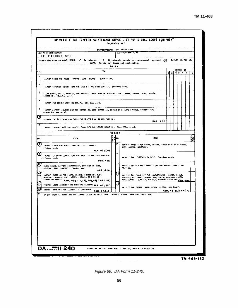
TM 11-468
Figure 69. DA Form 11-240.
56
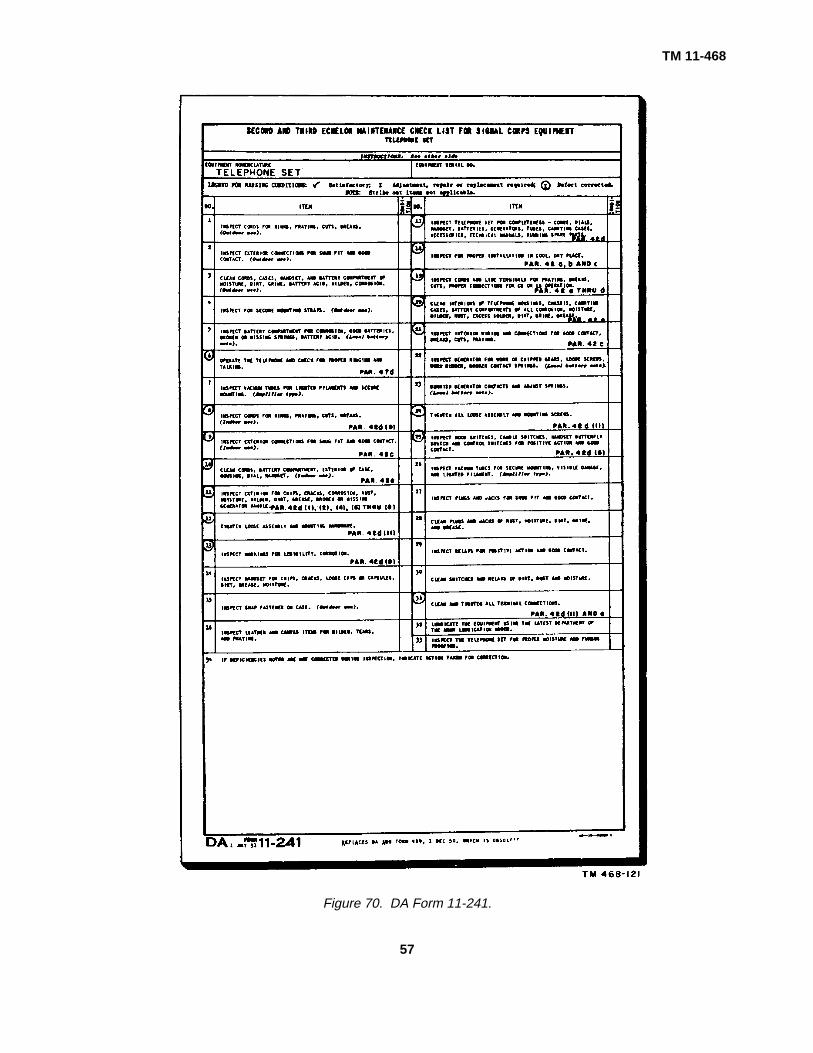
TM 11-468
Figure 70. DA Form 11-241.
57
TM 11-468
(c) Check the cover for cracks orholes.
(4) Ringer.(a) See that the ringer is mounted
properly and securely.(b) See that the gongs are not loose.(c) Inspect the coils for nicks, dents,
and improper connections.(d) Inspect the biasing spring to see
that it is not broken or lacking intension.
(5) Induction coil.(a) See that the coil is mounted
securely.(b) Inspect the windings for nicks,
dents, and breaks.(6) Hookswitch.
(a) Check the springs for bends,rust, pitting, etc.
(b) Check for free lever action.(c) See that the contacts make and
break properly.(7) Case.
(a) Inspect for cracks or brokenpieces.
(b) Check the bottom of thedeskstand for the condition of therubber or felt pads.
(c) See that all parts are clean.(8) Dial.
(a) See that the dial is mountedsecurely.
(b) Inspect for bent finger wheel orfinger stop.
(c) See that the dial is not operatingsluggishly or quickly.
(d) See that the number card islegible.
(9) Cords.(a) Straighten the cords that are
twisted.(b) See that the stay cords or hooks
are secured.(c) Inspect for bad tips and frayed or
worn places.(10) Wire forms.
(a) Check for correct color-code andconnections.
(b) Check for frayed or broken wires.(c) Check the solder connections.(d) Check the form lacing.(e) Check the wire lengths to insure
that the smallest length possibleis used.
(11) Screws and nuts. Check all parts formissing, stripped, or worn screws andnuts.
e. Cleaning. Use a clean, dry, lint-free cloth,or a dry brush for cleaning. If necessary, except forelectrical contacts, moisten the cloth or brush withSolvent, Dry Cleaning (SD); then wipe the parts dry witha cloth.
Section III. LUBRICATION
43. GeneralThe equipment described in this manual does
not require extensive and frequent lubrication. With theexception of the dial, all parts are lubricated by themanufacturer, and no further lubrication is required.Lubricate the dial only when necessary; for example,when the dial has been taken apart for adjustment, orwhen the dial has been used for some period of time inan atmosphere conducive to corrosion. There is nodefinite schedule of dial lubrication; this depends onmaintenance procedures at a particular installation.
44. LubricantThe following table lists the lubricants required
for servicing Dial TA-45(*)/GT. Do not use any otherlubricants. The use of other than the recommendedlubricants may result in faulty operation and eventualbreakdown of the dial.
Productsymbol
Standard nomenclature Specification and QMC stockNo.
OCW Oil, Clock and Watch-- U. S. Army spec No.2-47B; QMC No. 140-680.
OAI Oil, Lubricating, Air- AN-O-11: QMC No.craft Instrument 14-0-1341.(Low Volatility).
45. Lubrication Instructions(fig. 71)a. Definitions.
(1) A drop of oil is released from the endof a bare tinned copper No. 22 B & Swire, after the wire has been dippedone-half inch into the oil and quicklywithdrawn.
(2) A dip of oil is retained in the bristles ofa No. 6 camel’s-hair brush (BrushTL72)
58
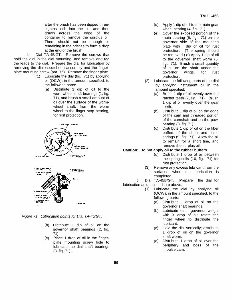
after the brush has been dipped three-eighths inch into the oil, and thendrawn across the edge of thecontainer to remove the surplus oil.There should not be enough oilremaining in the bristles to form a dropat the end of the brush.
b. Dial TA-45/GT. Remove the screws thathold the dial in the dial mounting, and remove and tagthe leads to the dial. Prepare the dial for lubrication byremoving the dial escutcheon assembly and the finger-plate mounting screw (par. 76). Remove the finger plate.
(1) Lubricate the dial (fig. 71) by applyingoil (OCW), in the amount specified, tothe following parts:(a) Distribute 1 dip of oil to the
wormwheel shaft bearings (1, fig.71), and brush a small amount ofoil over the surface of the worm-wheel shaft, from the wormwheel to the finger stop bearing,for rust protection.
Figure 71. Lubrication points for Dial TA-45/GT.
(b) Distribute 1 dip of oil on thegovernor shaft bearings (2, fig.71)
(c) Place 1 drop of oil in the finger-plate mounting screw hole tolubricate the dial shaft bearings(3, fig. 71).
TM 11-468
(d) Apply 1 dip of oil to the main gearwheel bearing (4, fig. 71).
(e) Cover the exposed portion of themain bearing (5, fig. 71) on thegovernor side of the mountingplate with I dip of oil for rustprotection. (The spring shouldbe removed.) (f) Apply 1 dip of oilto the governor shaft worm (6,fig. 71). Brush a small quantityof oil on the shaft under thegovernor wings, for rustprotection.
(2) Lubricate the following parts of the dialby applying instrument oil in theamount specified:
(a) Brush 1 dip of oil evenly over theratchet teeth (7, fig. 71). Brush1 dip of oil evenly over the gearteeth.
(b) Distribute 1 dip of oil on the edgeof the cam and threaded portionof the camshaft and on the pawlbearing (8, fig. 71).
(c) Distribute 1 dip of oil on the fiberbuffers of the shunt and pulsesprings (9, fig. 71). Allow the oilto remain for a short tine, andremove the surplus oil.
Caution: Do not apply oil to the rubber buffers.(d) Distribute 1 drop of oil between
the spring coils (10, fig. 71) forrust protection.
(3) Remove any excess lubricant from thesurfaces when the lubrication iscompleted.
c. Dial TA-45B/GT. Prepare the dial forlubrication as described in b above.
(1) Lubricate the dial by applying oil(OCW), in the amount specified, to thefollowing parts:(a) Distribute 1 drop of oil on the
governor shaft bearings.(b) Lubricate each governor weight
with X drop of oil; rotate thefinger wheel to distribute thelubricant.
(c) Hold the dial vertically; distribute1 drop of oil on the governorshaft worm.
(d) Distribute 1 drop of oil over theperiphery and boss of theimpulse cam.
59

(e) Apply I drop of oil to the lowerwasher and I drop of oil to the upper washer of thetrigger assembly.
TM 11-468
TM 11-468(2) Rotate the trigger from its normal
position and apply instrument oil to the trigger surfaces.
Section IV. TROUBLESHOOTING
46. Types of TroublesMost of the troubles that occur in substation
equipment result from a failure or malfunction in any ofthe four functions of the telephone set.
a. Signaling of the operator or seizing ofautomatic switching equipment.
b. Signaling of the telephone user.c. Transmitting of the message.d. Receiving of the message.
47. Troubleshooting Considerationsa. Before beginning any troubleshooting
procedure, investigate the effect of the following items onthe cause of the trouble:
(1) The type of service involved (dial ormanual).
(2) The type of apparatus involved.(3) The effect of the trouble on the
telephone user’s service.(4) The weather conditions at the time the
trouble was reported. Rain, sleet,snow, or ice may cause shorts orgrounds, which, in turn, may cause apermanent signal.
(5) The maintenance history of theequipment involved If frequentmaintenance has been performed onthe equipment, replace it, rather thancontinue needless repairs oradjustments.
b. Before the repairman is sent to work on anyequipment, certain procedures should be completed bythe wire chief at the test desk.
(1) A TMT (transmission test) to test thecondition of the transmitter or receiver.This is done only when the telephoneis not completely out of order.
(2) Tests to locate the source of troubleas being definitely outside of thecentral office.
c. Frequently several factors may cause aninterruption or impairment of service. A logical step-by-step procedure must be followed to localize andeliminate the sources of trouble. Paragraphs 49 through61 describe the procedures to be followed in localizingthe most common troubles. To eliminate all sources oftrouble, follow the troubleshooting procedures tocompletion, even if the source of trouble has beendiscovered in one of the intermediate steps.
This may result in the discovery of incipient troubles,which may later develop into serious troubles,necessitating another service call.
d. When arriving at the location of thesubstation that has been reported as defective, proceedas follows:
(1) Determine the exact nature of thetrouble. Most troubles will be reportedby personnel unfamiliar with theoperation of telephone circuits. Thetrouble may have been exaggerated orunderestimated. In some instances,the trouble may result fromunfamiliarity with the proper procedurefor using a telephone set. If this is thecase, instruct the telephone user inthe proper procedures; however, atest must be made to determine thegeneral operating condition of theequipment. Test for proper ringingand transmission by calling theoperator or test desk (par. 80).
(2) Check the equipment for obviousfaults. Examine the equipment and allwiring for mechanical damage.Determine if the telephone set hasbeen dropped or damaged. Check thewiring for breaks, torn or damagedinsulation, and proper connection toterminals.
(3) Test at the cross-connecting box oraerial cable terminal first. The firstprocedure to be followed whendetermining the cause of any troubleis to test at, the cross-connecting boxor aerial cable terminal. The properterminals will have been identified bythe wire chief. The procedures to befollowed in testing for shorts, opens,grounds, or crosses are outlined inparagraphs 57 through 61. Test at theproper terminals to determine if thesource of the trouble does not lie onthe central office side of theequipment. If the trouble does lie onthe central office, side, report this tothe wire chief. However, the subsetmust be checked to determine if it is ingood working order.
60

A simple test to determine the condition ofthe subset may be made as follows:(a) Request the wire chief to furnish
the numbers of a spare pair ofterminals. This may beaccomplished by calling the wirechief from a nearby telephone orby connecting Test Set TS-365/GT across the terminals of agood pair and dialing the numberassociated with the test desk.
(b) Connect the test handset acrossthe spare terminals to determineif they are in good working order.
(c) Connect the telephone set to betested to the new terminals. Callthe test desk and instruct the testdesk man to run a TMT. If notest desk is available, call thewire chief at the test board or testturret. Determine whethertransmission and reception areacceptable. Instruct the test manto ring on the line. If any of theabove tests indicates that there isa trouble in the equipment, followthe procedure for clearing theparticular trouble.
(4) Test the inside wiring before testingthe substation equipment. If theindicated trouble lies on the substationside of the equipment, always checkthe inside wiring first. Remove thecover from the connecting block anddisconnect the leads from thetelephone set. Connect the testhandset across the terminals of theconnecting block to determine if the in
TM 11-468side wiring is in good working order. In
most instances, it will be more advisable to replacedefective inside wiring than to try to determine the exactlocation of the trouble.
e. The troubleshooting procedures outlined inparagraphs 50 through 55 apply specifically to theschematic and wiring diagrams for Telephone TP-6-A.When testing other TP-6 type telephones, refer to the wiringand schematic diagrams for that particular equipment (figs.90 through 103). Troubleshooting procedures forTelephone Set TA-236/FT are given in paragraph 61.48. Troubleshooting Charts
Note. The abbreviations appearing in theSymptom column of the troubleshooting charts are thestandard abbreviations used on trouble tickets (DAForm 11-23 Telephone Trouble Report). Thesedesignations are explained in the first chart and areused without explanation in the second chart.
a. Telephone TP-6-A. The troubleshooting chartbelow lists the common troubles that may occur in the TP-6-A and other TP-6-type telephone sets. Paragraphs 49through 60 describe the methods to be used in locatingsources of troubles. Wherever internal wiring of thetelephone set is found to be defective, replace it with theproperly colored wiring. Replace all defective parts; do notattempt to repair them. After clearing a reported trouble, callthe test desk or test board, and test the general telephoneoperation. If extensive replacement of parts is required,replace the telephone set with a new or reconditioned one.
Symptom Probable Trouble Correction
Cannot raise operator (CRO) ------------- Open black handset lead-------------------- Replace handset cord.No dial tone (NDT)--------------------------- Open transmitter------------------------------- Replace transmitter.
Dirty hookswitch contact--------------------- Clean or burnish contacts.Open yellow instrument lead --------------- Repair or replace lead.Open primary of induction coil ------------- Replace induction coil.Open line from cross-connecting box---- Repair open conductor.
to connecting block.Permanent signal (PERM)---------------------- Crossed yellow and black instrument---- Repair or replace leads.
leads.Crossed yellow and green instrument --- Repair or replace leads.
leads.Crossed yellow and red instrument------- Repair or replace leads.
leads.Crossed hookswitch leads ------------------ Repair insulation.Crossed capacitor leads--------------------- Repair insulation.Shorted ringing capacitor-------------------- Replace capacitor.Short in deskstand cord --------------------- Replace deskstand cord.Ring ground------------------------------------- Repair insulation of ring conductor.
61

TM 11-468
Symptom Probable Trouble Correction
Permanent signal (PERM)----------------- Both sides grounded ------------------------- Repair insulation of both tip and ringconductor.
Tip-ring cross ----------------------------------- Refer to TM 11-757. Repair orreplace lead.
Ring-tip cross ---------------------------------- Refer to TM 11-757. Repair orreplace lead.
Bell does not ring (BDR) ------------------- Open ringer or ringer leads ----------------- Replace ringer if there is an openingin the coils.
Open ringing capacitor or capacitor ------ Replace capacitor.leads.
Shorted ringer coils --------------------------- Replace ringer.Mechanical defects in ringer --------------- Replace ringer.
Transmitter dead, or cannot be heard-- Crossed red and black leads in handset Repair or replace leads.CBH). cord.
Shorted or packed transmitter ------------- Replace transmitter unit.Receiver dead, or cannot hear (CH)---- Crossed red and white leads in handset Replace handset cord.
cord.Crossed black and white leads in hand- Replace handset cord.
set cord.Open green instrument lead---------------- Replace lead.Open white lead in handset cord---------- Replace handset cord.Dirty dial spring contacts -------------------- Clean dial springs or replace dial.Dirty receiver spring contacts -------------- Clean contacts.Receiver contacts not contacting --------- Bend contacts.
receiver.Shorted receiver unit ------------------------- Replace receiver unit
Cannot be heard well (CBHW) ----------- Open or shorted talking capacitor--------- Replace capacitor.Open black instrument lead ---------------- Replace or repair lead.
Cannot hear well (CHW) ------------------- Open red instrument lead ------------------- Replace or repair lead.Open red lead in handset cord ------------ Replace handset cord.Open secondary winding of induction Replace induction coil.
coil.Open tertiary winding of induction coil--- Replace induction coil.Crossed red and white leads of hand---- Replace handset cord.
set cord.Crossed red and green instrument leads Repair or replace leads.Crossed green and black instrument ---- Repair or replace leads.
leads.Crossed red and black instrument-------- Repair or replace leads.
leads.Shorted primary winding of induction ---- Replace induction coil.
coil.Shorted tertiary winding of induction ----- Replace induction coil.
coil.Shorted secondary winding of induction Replace induction coil.
coil.Clicks in ear while dialing ------------------ Open red instrument lead ------------------- Repair or replace leads.
Open red lead in handset cord ------------ Replace handset cord.Noisy line--------------------------------------- Tip ground--------------------------------------- Repair insulation of tip conductor.
Defective handset cord------------------- Replace cord.Cross talk -------------------------------------- Tip-tip cross------------------------------------- Refer to TM 11-757.
Ring-ring cross --------------------------------- Refer to TM 11-757.
62

b. Telephone Set TA-236/PT. Thetroubleshooting chart below lists the troublesthat may occur in Telephone Set TA-236/PT.
c. All terminals terminal board, unlessotherwise stated. Obtain tests,
TM 11-468d. reports, and records from the wire chief.
Paragraphs 56 through 61 describe methodsfor locating sources of trouble
Symptom Probable Trouble Correction
1. NDT; CRO (manual) --------------------- Open cable lead ------------------------------- Refer to wire chief for testing.Open line wire ---------------------------------- Locate and repair.Open inside wire------------------------------- Locate and repair or replace.Open protector fuse -------------------------- Replace defective fuse.Open RED deskstand cord lead----------- Substitute YEL deskstand cord lead and transfer
the BLK ringer lead from terminal G to terminal L1.Open GY-GRN set lead --------------------- Repair if practicable; otherwise, replace the set.Faulty D-E switch contacts ----------------- Clean (par. 71); if this fails to clear the trouble, replace
the set.Open GY-WH set lead ----------------------- Repair if practicable; otherwise replace the set.Open BLU dial lead (dial sets -------------- Repair or replace the lead with one of similar coloronly). code, otherwise replace the dial.Faulty dial pulse contacts (dial------------- Clean (par. 71); if this fails to clear the trouble, re-
sets only). place the dial.Open GRN dial lead (dial sets ------------- Repair or replace the lead or replace dial.
only).Open network between terminals--------- Replace the set.
RR and R.Open RED handset cord lead-------------- Replace the cord.Open or loose connection at the ---------- Tighten faulty contact.
transmitter cup terminals.Faulty contact between cup ---------------- Clean contacts, element ring cap, and closure cap
contacts and transmitter element. (fig. 36) with solvent (SD). Do not burnish thesecontacts. If trouble continues, adjust the contacts.
Open transmitter element ------------------- Replace the element.Open BLK handset lead --------------------- Replace the handset cord.Open network between terminals Replace the set.
B and C.Open GY-BRN set lead---------------------- Repair the lead or replace the set.Faulty C-B switch contacts ----------------- Clean (par. 71); if this fails to clear the trouble,
replace the set.Open GY-YEL set lead ---------------------- Repair the lead or replace the set.Open GRN deskstand lead ----------------- Substitute the YEL for the GRN lead and transfer
the BLK ringer lead from terminal G to LI. Besure to transfer the YEL lead from the ring side tothe tip side of the line at the connecting block.
Open line, tip side ----------------------------- Locate and repair the line.
Note. In manual operation the GY-WHT set leadfrom the switch is connected to terminal RR insteadof terminal F as in dial operation (fig. 67). Except forthe steps noted above in this subparagraph (dial setsonly), the same procedure is applied in locating thisfault.
2. PERM (permanent signal Shorted ring and tip in the line ------------- Locate and clear (par. 59).at the central office). Crossed RED and GRN deskstand Substitute the YEL for the GRN deskstand cord
cord leads. lead and transfer the BLK ringer lead from terminal Gto L1
Crossed YEL and GCRN desk- Disconnect the YEL lead from terminal G and fromstand cord leads. the ring side of the line at the connecting block;
transfer the BLK ringer lead from terminal G to L1.Switch contact D crossed with Replace the set.
contact B.Short-circuited capacitor C4 Replace the set.
(fig. 59).Grounded line, ring side --------------------- Locate and clear (par. 59).
63

TM 11-468
Symptom Probable Trouble Correction
3. BDR---------------------------------------------- Open ringer coil -------------------------------- Replace the ringer coil.Open ringer lead------------------------------- Repair or replace the lead; otherwise, replace the
ringer coil.
Note. When not more than one set is connected tothe line, maintain temporary service as follows. If thetrouble s caused by an open 1K winding, connect astrap from the O to the K terminal. If caused by anopen 2,ohm winding, connect a strap from terminal Ato L2 (fig. 59).
Open YEL deskstand lead ------------------ Transfer the BLK ringer lead from terminal G to L1.Wrong bias tension --------------------------- Correct the fault.Ringer cutoff feature operated ------------- Instruct all using personnel.Improper ringer connections --------------- Correct the fault.Mechanical failure of ringer----------------- Replace the ringer.
component.4. CBH ------------------------------------------ Loose connection------------------------------ Check the line and the transmitter circuit for continuity.
RED and BLK handset cord Replace the handset cord.leads crossed.
Transmitter element carbon Replace transmitter element.grains packed.
User confusing the transmitter Instruct the user.and receiver ends of the handset.
User positioning the transmitter Explain the necessity for proper use, and demonstratetoo far away from the mouth. proper positioning. When tests indicate that noOther faulty user practices. plant fault exists, observe for faulty use and explain
to the user.Central office equipment failure Arrange to have the line tested. Make corrections
according to tester report.Network assembly failure ------------------- Replace the set.Switch assembly failure---------------------- Replace the set.
5. CH (fig. 67) -------------------------------- Network failure --------------------------------- Replace the set.Loose connection between WH Tighten connection.
handset cord lead and terminal GN.Open WH lead connecting terminal Replace handset cord.
G with receiver element terminal.Loose connection at receiver Tighten connection.
element terminal.Faulty receiver element---------------------- Replace receiver element.Open WH lead connecting receiver Replace handset cord.
element with terminal R.Dial off-normal contacts crossed Replace the dial.
(dial operation only).Switch contacts G-F fail to open Replace the set.
when the handset is removedfrom the cradle.
Faulty use --------------------------------------- Instruct the user.6. CHW ----------------------------------------- Faulty network---------------------------------- Replace the set.
Loose connection------------------------------ Check receiver circuit connections for tightness.High resistance short circuit at Replace the set.
switch contact assembly.Faulty receiver element---------------------- Replace the element.Faulty use --------------------------------------- Instruct the user.
64
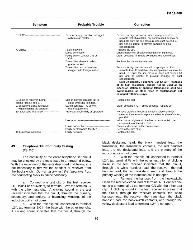
TM 11-468
Symptom Probable Trouble Correction
6. CHW ----------------------------------------- Receiver cap perforations clogged Remove foreign substance with a spudger or otherwith foreign matter. suitable tool. If available, dry compressed air may be
used. Be sure the line pressure does not exceed 60psi, and be careful to prevent damage by blastconcentration.
7. CBHW --------------------------------------- Faulty network --------------------------------- Replace the set.Loose connection------------------------------ Check transmitter circuit connections for tightness.Faulty switch contact D-E or Clean contacts. If trouble continues, replace the set.
C-B.Transmitter element carbon Replace the transmitter element.
grains packed.Transmitter cap perforations Remove foreign substances with a spudger or other
clogged with foreign matter. suitable tool. If available, dry compressed air may beused. Be sure the line pressure does not exceed 60psi, and be careful to prevent damage by blastconcentration.Note .In general, Telephone Set TA-23PT (because
of its high resistance) should not be used as anextension station or operator telephone at cord-typeswitchboards, or other types of switchboards notequipped with line relays.
8. Clicks at receiver during ---------------- Dial off-normal contacts fail to Replace the dial.dialing (figs.64 and 67). close while dial is in use.9. Excessive clicks at receiver- Switch contacts F-G dirty or Clean contacts F-G. If clicks continue, replace set
when flashing the operator. out of adjustment.10. Excessive line noise-------------------- Protector blocks dirty or operated Remove protector blocks and check noise condition;
clean or if necessary, replace the blocks.(See Caution,par.15d.)
Line induction----------------------------------- When noise originates in the line or cable, obtain thecooperation of the wire chief.
Loose connections ---------------------------- Check and correct faulty connections.Faulty central office facilities --------------- Refer to the wire chief.
11.Excessive sidetone---------------------- Faulty network---------------------------------- Replace the set.
49. Telephone TP- Continuity Testing(fig. 90)
The continuity of the entire telephone set circuitmay be checked by the tests listed in a through d below.With the exception of the tests described in d below, it isnot necessary to remove the handset or receiver fromthe hookswitch. Do not disconnect the telephone fromthe connecting block to check continuity.
a. Connect one test clip of the test receiver(TS-190/U or equivalent) to terminal L2Y; tap terminal Cwith the other test clip. A clicking sound in the testreceiver indicates that the circuit, through the primary,secondary, and tertiary, or balancing, windings of theinduction coil is not open.
b. With the test clip still connected to terminalL2Y, tap terminal BK in the base with the other test clip.A clicking sound indicates that the circuit, through the
black deskstand lead, the black handset lead, thetransmitter, the transmitter contacts, the red handsetlead, the red deskstand lead, and the primary of theinduction coil is not open.
c. With the test clip still connected to terminalL2Y, tap terminal W with the other test clip. A clickingnoise in the test receiver indicates that the circuit,through the white handset lead, the receiver, the redhandset lead, the red deskstand lead, and through theprimary winding of the induction coil is not open.
d. Remove the handset from the hookswitch.Open the red deskstand lead at terminal R. Connect onetest clip to terminal L1 tap terminal GN with the other testclip. A clicking sound in the test receiver indicates thatthe circuit, through the receiver contacts, the whitehandset lead, the receiver, the transmitter, the blackhandset lead, the hookswitch contacts, and through theyellow desk stand lead to terminal L2Y is not open.
65

Figure 72. Telephone TP-6-A, with dial, schematic diagram.
50. Telephone TP-A Continuity Testing(figs. 72, 73, and 74)A wiring diagram of Telephone TP-6-A
(Contelco) is shown in figure 73. The circuits aresubstantially the same as those of Telephone TP-6. Thewiring in figure 73 is shown partly by solid lines and partlyby dotted lines to help understand the circuit continuitytests. From any point on any solid line a path can betraced to the ring side of the line at terminal L1. Thus, totest any of these paths for continuity only, connect one ofthe test leads from the test set to the tip side of the lineat terminal L2Y and, with the other test clip, touch thatpart of the path under test at the point most remote fromterminal L1. The test in a through g below assumes thatthe line circuit to terminals L1 and L2Y is good. If a clickis not heard at the circuit farthest from terminal L1, testat suitable test points, backward through the circuit undertest, to terminal L1. When a click is heard, an open liesbetween that point and the last point tested. Unlessnoted otherwise, leave the receiver on the hookswitchthroughout the following tests.
a. To test the secondary, tertiary (balancing),and primary windings of the induction coil, 66 w, withdial, schematic diagram. connect one test set lead toterminal L2Y. Touch the free test lead to terminal No. 4of capacitor A.
A click indicates continuity between the test point andterminal L1.
Note. To avoid repetition, one testset lead will remain on terminal L2Ythroughout the tests for continuitybetween test points and terminal L1.b. To test the brown deskstand lead, the
pulsing contacts of the dial, the black handset cord lead,the transmitter element, the red handset cord lead, andthe primary winding of the induction coil to terminal L1,touch the free test lead to hookswitch contact No. 1. Aclick indicates continuity in the part of the circuit undertest.
Note. The numbered hookswitchterminals (fig. 73) provide referencepoints. They do not appear in thetelephone set.c. To test the black deskstand lead running
from terminal No. 1 at capacitor A, touch the free lead toterminal No. 1. A click indicates that the black lead isgood.
d. To test the blue deskstand lead, thereceiver contacts of the dial, the white handset cord lead,the receiver element, and the handset strap, touch thefree test set lead to hookswitch contact
66

TM 11-468
Figure 73. Telephone TP-6-A, manual operation, wiring diagram.
Figure 74. Telephone TP-6-A, with dial, wiring diagram.
67
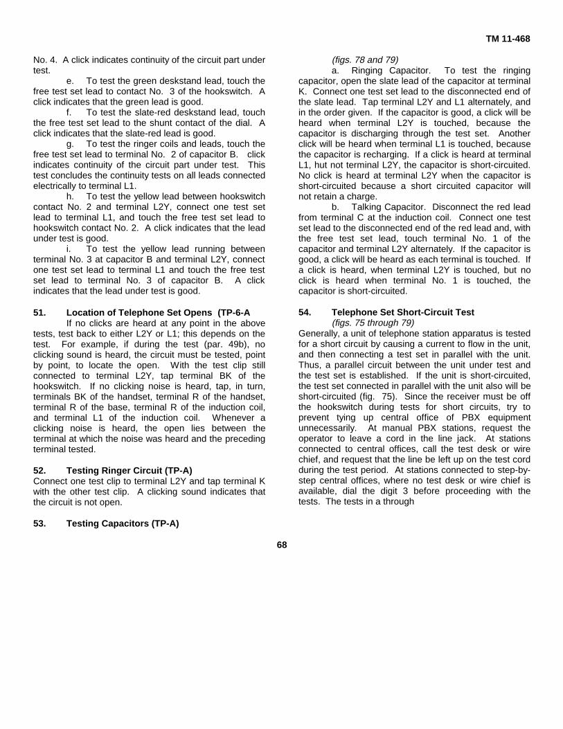
TM 11-468
No. 4. A click indicates continuity of the circuit part undertest.
e. To test the green deskstand lead, touch thefree test set lead to contact No. 3 of the hookswitch. Aclick indicates that the green lead is good.
f. To test the slate-red deskstand lead, touchthe free test set lead to the shunt contact of the dial. Aclick indicates that the slate-red lead is good.
g. To test the ringer coils and leads, touch thefree test set lead to terminal No. 2 of capacitor B. clickindicates continuity of the circuit part under test. Thistest concludes the continuity tests on all leads connectedelectrically to terminal L1.
h. To test the yellow lead between hookswitchcontact No. 2 and terminal L2Y, connect one test setlead to terminal L1, and touch the free test set lead tohookswitch contact No. 2. A click indicates that the leadunder test is good.
i. To test the yellow lead running betweenterminal No. 3 at capacitor B and terminal L2Y, connectone test set lead to terminal L1 and touch the free testset lead to terminal No. 3 of capacitor B. A clickindicates that the lead under test is good.
51. Location of Telephone Set Opens (TP-6-AIf no clicks are heard at any point in the above
tests, test back to either L2Y or L1; this depends on thetest. For example, if during the test (par. 49b), noclicking sound is heard, the circuit must be tested, pointby point, to locate the open. With the test clip stillconnected to terminal L2Y, tap terminal BK of thehookswitch. If no clicking noise is heard, tap, in turn,terminals BK of the handset, terminal R of the handset,terminal R of the base, terminal R of the induction coil,and terminal L1 of the induction coil. Whenever aclicking noise is heard, the open lies between theterminal at which the noise was heard and the precedingterminal tested.
52. Testing Ringer Circuit (TP-A)Connect one test clip to terminal L2Y and tap terminal Kwith the other test clip. A clicking sound indicates thatthe circuit is not open.
53. Testing Capacitors (TP-A)
(figs. 78 and 79)a. Ringing Capacitor. To test the ringing
capacitor, open the slate lead of the capacitor at terminalK. Connect one test set lead to the disconnected end ofthe slate lead. Tap terminal L2Y and L1 alternately, andin the order given. If the capacitor is good, a click will beheard when terminal L2Y is touched, because thecapacitor is discharging through the test set. Anotherclick will be heard when terminal L1 is touched, becausethe capacitor is recharging. If a click is heard at terminalL1, hut not terminal L2Y, the capacitor is short-circuited.No click is heard at terminal L2Y when the capacitor isshort-circuited because a short circuited capacitor willnot retain a charge.
b. Talking Capacitor. Disconnect the red leadfrom terminal C at the induction coil. Connect one testset lead to the disconnected end of the red lead and, withthe free test set lead, touch terminal No. 1 of thecapacitor and terminal L2Y alternately. If the capacitor isgood, a click will be heard as each terminal is touched. Ifa click is heard, when terminal L2Y is touched, but noclick is heard when terminal No. 1 is touched, thecapacitor is short-circuited.
54. Telephone Set Short-Circuit Test(figs. 75 through 79)
Generally, a unit of telephone station apparatus is testedfor a short circuit by causing a current to flow in the unit,and then connecting a test set in parallel with the unit.Thus, a parallel circuit between the unit under test andthe test set is established. If the unit is short-circuited,the test set connected in parallel with the unit also will beshort-circuited (fig. 75). Since the receiver must be offthe hookswitch during tests for short circuits, try toprevent tying up central office of PBX equipmentunnecessarily. At manual PBX stations, request theoperator to leave a cord in the line jack. At stationsconnected to central offices, call the test desk or wirechief, and request that the line be left up on the test cordduring the test period. At stations connected to step-by-step central offices, where no test desk or wire chief isavailable, dial the digit 3 before proceeding with thetests. The tests in a through
68
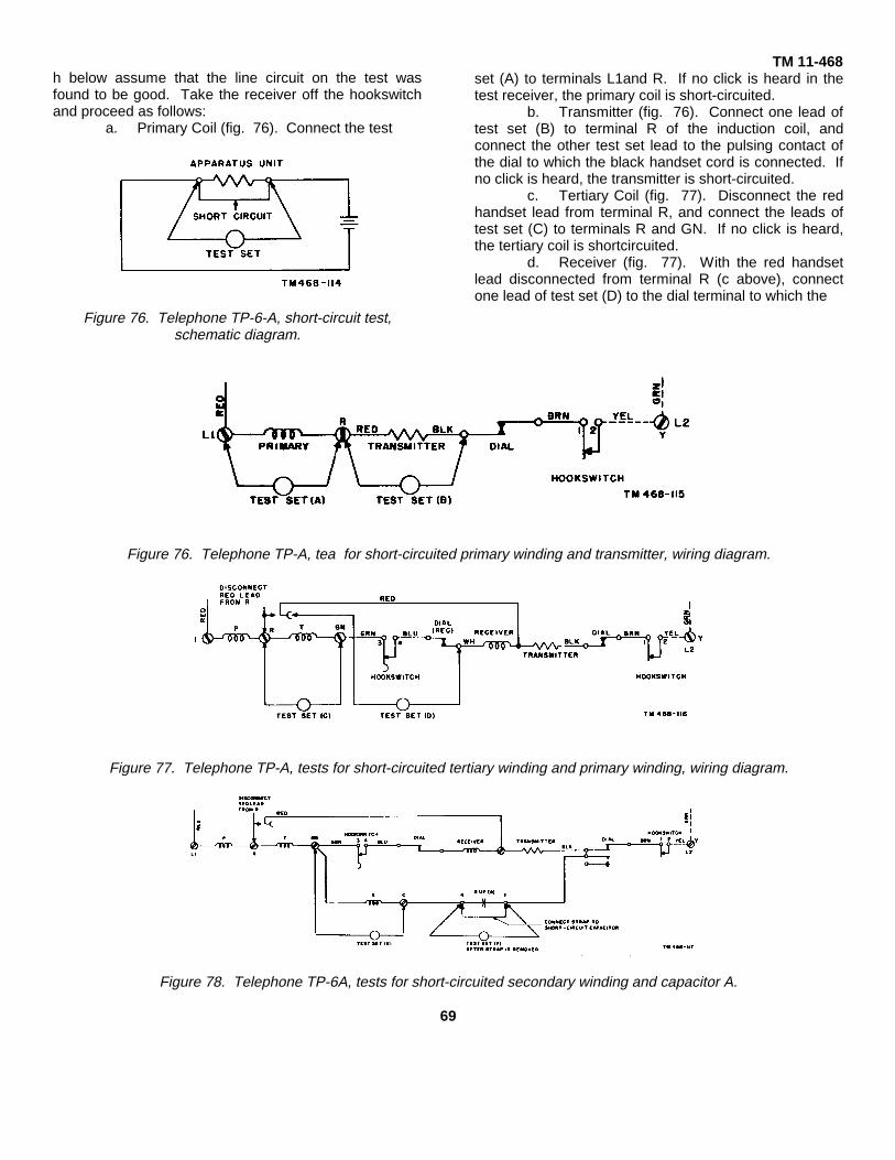
h below assume that the line circuit on the test wasfound to be good. Take the receiver off the hookswitchand proceed as follows:
a. Primary Coil (fig. 76). Connect the test
Figure 76. Telephone TP-6-A, short-circuit test,schematic diagram.
TM 11-468set (A) to terminals L1and R. If no click is heard in thetest receiver, the primary coil is short-circuited.
b. Transmitter (fig. 76). Connect one lead oftest set (B) to terminal R of the induction coil, andconnect the other test set lead to the pulsing contact ofthe dial to which the black handset cord is connected. Ifno click is heard, the transmitter is short-circuited.
c. Tertiary Coil (fig. 77). Disconnect the redhandset lead from terminal R, and connect the leads oftest set (C) to terminals R and GN. If no click is heard,the tertiary coil is shortcircuited.
d. Receiver (fig. 77). With the red handsetlead disconnected from terminal R (c above), connectone lead of test set (D) to the dial terminal to which the
Figure 76. Telephone TP-A, tea for short-circuited primary winding and transmitter, wiring diagram.
Figure 77. Telephone TP-A, tests for short-circuited tertiary winding and primary winding, wiring diagram.
Figure 78. Telephone TP-6A, tests for short-circuited secondary winding and capacitor A.
69

TM 11-468
Figure 79. Telephone TP-6-A, tests for short-circuited ringer coil and capacitor B.
white handset cord is connected and connect the othertest set lead to the disconnected end of the red handsetlead. If no click is heard, the receiver winding is short-circuited.
e. Secondary Coil (fig. 78). With the redhandset lead disconnected from terminal R (c above),connect a short-circuiting strap across terminals No. 4and 1 of capacitor A. Connect one lead of test set (E)lead to terminal C and touch the other lead to terminalGN. If no click is heard, the secondary coil is short-circuited.
f. Capacitor A (fig. 78). Remove the short-circuiting strap from capacitor A (e above) and connectthe leads of test set (F) across terminals No. 4 and No.1 of capacitor A. If no click is heard, capacitor A is short-circuited.
Note Replace the receiver on thehookswitch and reconnect the redhandset cord lead to terminal R of theinduction coil.g. Ringer Coils (fig. 79)
(1) Connect a short-circuiting strap acrossterminals No. 2 and No. 3 of capacitorB. Connect one lead of test set (G) tothe strap that normally connects thetwo ringer coils and, with the other testlead, touch terminal L1. If no click isheard, the ringer coil is short-circuited.
(2) If a click is heard, remove the test setlead from terminal L1 and, with thesame test set lead, touch terminal K.If no click is heard at this point, the coilunder test is short-circuited.
h. Capacitor B (fig. 79). Remove the strapfrom terminals No. 2 and No. 3 of capacitor B. Connectthe leads of test set (H) across terminals No. 2 and No. 3of capacitor B. If no click is heard, capacitor B is short-circuited.
55. Locating Crosses in Telephone Set Leads,Telephone TP-A(fig. 80)To locate crosses between any two leads in a
telephone set, first consider the nature of the servicefailure present. From this information a clue may beobtained, which will help to locate the fault. If thetelephone user cannot hear, the fault may be in thereceiver circuit. If the user cannot be heard, usually thefault will be in the transmitter circuit. When the dial tonecannot be heard or the operator does riot answer, thefault is probably in the transmitter circuit. Make the testsin a through e below with the receiver on the hookswitch.In f through h below, test with the hookswitch plungerdepressed.
a. Crossed Green and Yellow DeskstandLeads. This fault will cause a permanent signal toappear at the central office or PBX.
(1) Disconnect the green lead at terminalGN of the induction coil.
(2) Connect one test set lead to terminalGN. Touch the other test set lead tothe disconnected end of the greenlead.
(3) If a click is heard, the leads under testare crossed.
b. Crossed Brown and Yellow DeskstandLeads. This fault will cause a permanent signal toappear at the central office or the PBX.
(1) Disconnect the brown lead at the dialterminal.
(2) Connect one test lead to terminal L1of the induction coil. Touch the othertest set lead to the disconnected endof the brown lead.
(3) If a click is heard, the leads under testare crossed.
70
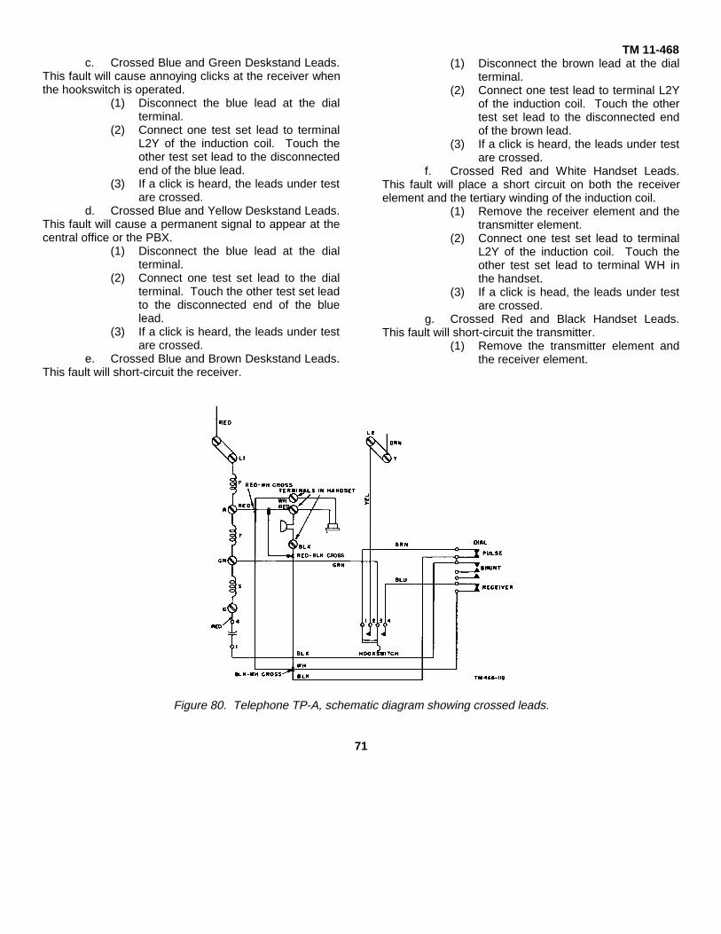
c. Crossed Blue and Green Deskstand Leads.This fault will cause annoying clicks at the receiver whenthe hookswitch is operated.
(1) Disconnect the blue lead at the dialterminal.
(2) Connect one test set lead to terminalL2Y of the induction coil. Touch theother test set lead to the disconnectedend of the blue lead.
(3) If a click is heard, the leads under testare crossed.
d. Crossed Blue and Yellow Deskstand Leads.This fault will cause a permanent signal to appear at thecentral office or the PBX.
(1) Disconnect the blue lead at the dialterminal.
(2) Connect one test set lead to the dialterminal. Touch the other test set leadto the disconnected end of the bluelead.
(3) If a click is heard, the leads under testare crossed.
e. Crossed Blue and Brown Deskstand Leads.This fault will short-circuit the receiver.
TM 11-468(1) Disconnect the brown lead at the dial
terminal.(2) Connect one test lead to terminal L2Y
of the induction coil. Touch the othertest set lead to the disconnected endof the brown lead.
(3) If a click is heard, the leads under testare crossed.
f. Crossed Red and White Handset Leads.This fault will place a short circuit on both the receiverelement and the tertiary winding of the induction coil.
(1) Remove the receiver element and thetransmitter element.
(2) Connect one test set lead to terminalL2Y of the induction coil. Touch theother test set lead to terminal WH inthe handset.
(3) If a click is head, the leads under testare crossed.
g. Crossed Red and Black Handset Leads.This fault will short-circuit the transmitter.
(1) Remove the transmitter element andthe receiver element.
Figure 80. Telephone TP-A, schematic diagram showing crossed leads.
71
TM 11-468
(2) Disconnect the black lead at the dialterminal.
(3) Connect one test, set lead to terminalL2Y of the induction coil. Touch theother test set lead to terminal BLK inthe handset.
(4) If a click is heard, the leads under testare crossed.
h. Crossed White and Black Handset Leads.This fault will short-circuit the receiver.
(1) Remove the receiver cap and thereceiver element.
(2) Disconnect the white lead at the dialterminal.
(3) Connect one test set lead to terminal1,2Y of the induction coil. Touch theother test set lead to terminal WH inthe handset.
(4) If a click is heard, the leads under testare crossed.
56. Line Fault LocationMany subset troubles will be caused by faults in
the line cord and in the wiring leading to the cross-connecting box. There are four types of faults commonlyencountered: opens, shorts, grounds, and crosses. Thetesting procedures are described in paragraphs 57through 60 below.57. Line Opens
a. Causes. Opens are commonly caused bythe following:
(1) Cable wiring broken by excessivebending or twisting when the cable isplaced.
(2) Bullets piercing a cable or wire.(3) Kinks and nicks in the wire causing
the conductors to break.(4) Poor splices pulling out-under tension.(5) Inside wiring nails driven too far into
the insulation and breaking theconductors.
(6) Loose or dirty connections and lugs.(7) Blown, broken, or badly warped fuses.(8) Defects in the manufacture of the
wire.(9) Excessive strain on the wire at the
terminals causing conductors tobecome loose.
(10) Sharp or heavy objects striking a wireand causing a break.
b. Testing for and Locating Line Opens (fig.81).
(1) Connect one lead of the test receiverto the tip or ring conductor of the lineat the cross-connecting box. Tap theother conductor with the test pick. Aclick will be heard every time theconnection is made and every time it
is broken if the line is good at thatpoint. The absence of a clickindicates an open in the line towardthe central office. If the line tests goodtoward the central office, the open istoward the substation.
(2) The method used in locating an openis determined by the nature of the lineconstruction toward the substation. Ifopen wire is used, a quick inspectionof the entire line between the cross-connecting box and the substationmay reveal a broken lead. If nobroken lead is found, test at the end ofthe line. If the open is located backtoward the cross-connecting box, goback over the line and test atreasonably spaced intervals until theopen is located between two testpoints. Continue to test at intervalsuntil the fault is located between twoadjacent poles. If the leads are bothin the air, the fault is probably a poorlymade splice. If the pole line carriesanother working common batterycircuit, connect one lead of the test setto one side of this circuit, and connectthe spare lead to one side of the lineunder test. If a click or dial tone isheard, that lead is good. If no click ordial tone is heard, move the test setlead to the other side of the workingline and repeat the test. If a click ordial tone is heard, the side of thecircuit under test is good. Secure thefaulty lead toward the substation, andcut it toward the cross-connecting boxfar enough away from the pole tie topermit a sleeve splice later. Examinethe lead, locate the open, and makethe necessary repairs.
(3) If the open is in an insulated pairedwire proceed as in (2) above to thepoint where the fault is locatedbetween two adjacent poles. Becausethere is no advantage in determiningwhether the open is in the ring side orthe tip side of the line, cut the wiretoward the cross-connecting box, andtest at intervals along the line backtoward the cross-connecting box untilthe fault is located. Repair the open torestore service, and then inspect theline; the conditions that caused theinterruption in service should beremedied.
72
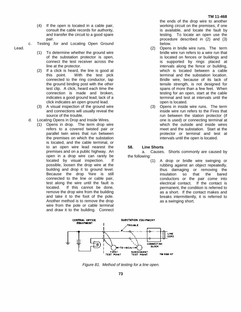
TM 11-468
(4) If the open is located in a cable pair,consult the cable records for authority,and transfer the circuit to a good sparepair.
c. Testing .for and Locating Open GroundLead.
(1) To determine whether the ground wireof the substation protector is open,connect the test receiver across theline at the protector.
(2) If a click is heard, the line is good atthis point. With the test pickconnected to the ring conductor, tapthe ground binding post with the othertest clip. A click, heard each time theconnection is made and broken,indicates a good ground lead; lack of aclick indicates an open ground lead.
(3) A visual inspection of the ground wireand connections will usually reveal thesource of the trouble.
d. Locating Opens in Drop and Inside Wires.(1) Opens in drop. The term drop wire
refers to a covered twisted pair orparallel twin wires that run betweenthe premises on which the substationis located, and the cable terminal, orto an open wire lead nearest thepremises and on a public highway. Anopen in a drop wire can rarely belocated by visual inspection. Ifpossible, loosen the drop wire at thebuilding and drop it to ground level.Because the drop %ire is stillconnected to the line or cable pair,test along the wire until the fault islocated. If this cannot be done,remove the drop wire from the buildingand take it to the foot of the pole.Another method is to remove the dropwire from the pole or cable terminaland draw it to the building. Connect
the ends of the drop wire to anotherworking circuit on the premises, if oneis available, and locate the fault bytesting. To locate an open use theprocedure described in (2) and (3)below.
(2) Opens in bridle wire runs. The termbridle wire run refers to a wire run thatis located on fences or buildings andis supported by rings placed atintervals along the fence or building,which is located between a cableterminal and the substation location.Bridle wire, because of its lack oftensile strength, is not designed forspans of more than a few feet. Whentesting for an open, start at the cableterminal and test at intervals until theopen is located.
(3) Opens in inside wire runs. The terminside wire run refers to the Fires thatrun between the station protector (ifone is used) or connecting terminal atwhich the outside and inside wiresmeet and the substation. Start at theprotector or terminal and test atintervals until the open is located.
58. Line Shortsa. Causes. Shorts commonly are caused by
the following:(1) A drop or bridle wire swinging or
rubbing against an object repeatedly,thus damaging or removing theinsulation so that the baredconductors or the pair come intoelectrical contact. If the contact ispermanent, the condition is referred toas a short. If the contact makes andbreaks intermittently, it is referred toas a swinging short.
Figure 81. Method of testing for a line open.
73
TM 11-468(2) A break in the insulation of a drop wire
at the drop (clamp, with the clampserving as the connection between thetwo conductors.
(3) Water settling on an old deteriorateddrop wire and acting as a conductor.
(4) Dirty faceplates on terminal cans thatserve as a conductor between twolugs.
(5) Wiring at any point of terminationextending too far and contactinganother lug.
(6) Inside wiring nails driven so that themetal nail penetrates the insulation oftwo leads in such a way that it makescontact with both.
(7) A pair of open wire leads havingexcessive slack between supports;these leads may swing into contactduring wind storms and produce aswinging short. A pair of open wireleads may wrap around each otherduring a violent wind storm or as theresult of a heavy impact against a linesupport and remain in this position.
b. Testing for and Locating Shorts (fig. 82).(1) Testing for line shorts requires a
knowledge of the physical position ofthe line under test with respect toother working lines. If the line undertest is a single pair of open wire leadsor a single drop, bridle or inside wirepair, testing is simplified. For any oneof these conditions, open either leadof the pair at fault toward the centraloffice or PBX, and connect the test setbetween the end of the lead justremoved and the terminal from whichthe lead was removed. If the open ismade on the tip side of the line, linebattery will flow from the ring side ofthe line out across the short circuit,back on the tip side of the line,through the test receiver, and back tothe source. A click will be heard in thetest receiver. If no short existed, therewould be no path from the ring side ofthe line to the tip side and no currentwould flow in the test set. However, ifthe pair under test is one of manyworking pairs in a cable, more caremust be taken to diagnose properlythe true nature of the fault.
(2) To test for a short-circuited pair in acable containing other workingcircuits, set up the conditions for test
as outlined 74 in (1) above with theopen on the tip side of the line. If aclick is heard, either the pair may beshorted, or the tip side of the lineunder test may be crossed with thering side of another working pair.Determine which fault exists bydisconnecting the ring side of the lineunder test from the line toward thecentral office and test again. If a clickis heard, the fault is a cross. If noclick is heard, the pair under test isshort-circuited.
(3) Close the tip side of the line and openthe ring side. Connect the test setbetween the open lead and theterminal from which the lead -vasremoved. A click will indicate eitherthat the pair under test is short-circuited, or the ring side of the lineunder test is crossed with the tip sideof another working pair. To determinewhich of the two conditions exist,disconnect the tip side of the pairunder test, and test again. If a click isheard, the fault is a cross. If no clickis heard, the fault is a short circuit.
Note. A faulty pair should be testedfor grounds before it is tested forshort circuits because a ground oneither side of the line may cause animproper diagnosis of the fault.c. Clearing Shorts From Line. The exact
location of a short in the open, drop, bridle, or insidewiring may be found by visual examination. If this isimpossible to perform, or if the wiring is damaged ordeteriorated, replace the wiring and rerun or reroute thewiring, or reinforce the insulation, as required.
59. Line GroundsMost line grounds occur at the substation
protector. This is caused by pitting of the carbon blockswhen high voltages arc across the .003-inch gap,causing the blocks to make contact with each other.Dust particles settling between the carbon blocks willcause them to make contact with each other.
a. Causes of Line Grounds. Line grounds arecaused by the following:
(1) Bare conductors of a worn drop wirewhich make contact with any grounded metallic objectwill often result in an intermittent ground.
(2) Wet or worn inside wiring whichmakes contact with a grounded metallic object.
74
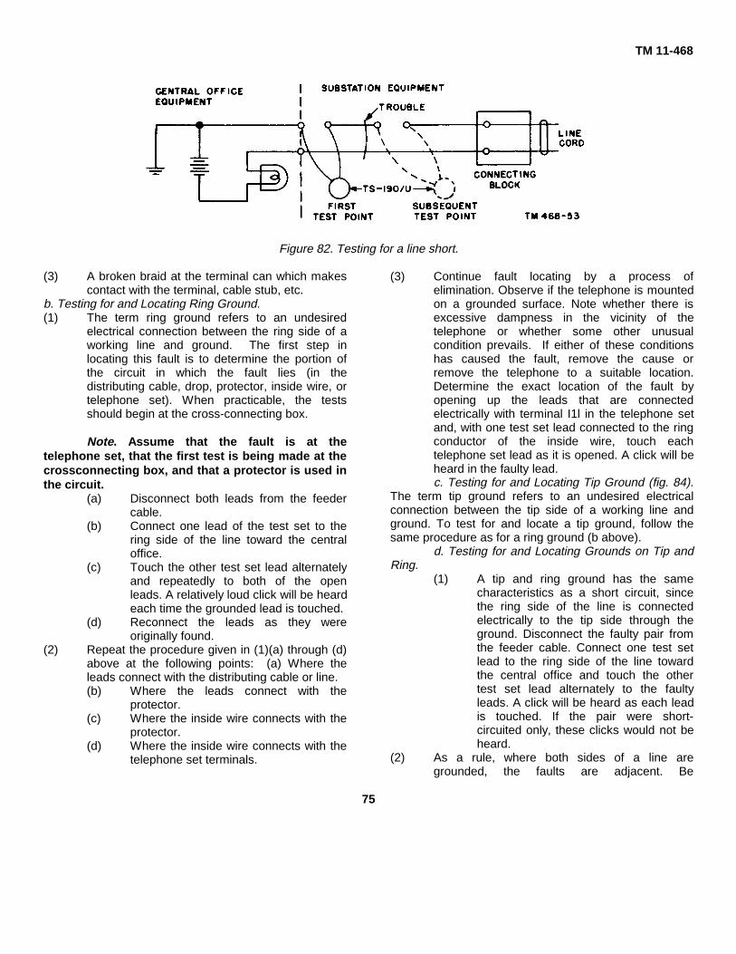
TM 11-468
Figure 82. Testing for a line short.
(3) A broken braid at the terminal can which makescontact with the terminal, cable stub, etc.
b. Testing for and Locating Ring Ground.(1) The term ring ground refers to an undesired
electrical connection between the ring side of aworking line and ground. The first step inlocating this fault is to determine the portion ofthe circuit in which the fault lies (in thedistributing cable, drop, protector, inside wire, ortelephone set). When practicable, the testsshould begin at the cross-connecting box.
Note. Assume that the fault is at thetelephone set, that the first test is being made at thecrossconnecting box, and that a protector is used inthe circuit.
(a) Disconnect both leads from the feedercable.
(b) Connect one lead of the test set to thering side of the line toward the centraloffice.
(c) Touch the other test set lead alternatelyand repeatedly to both of the openleads. A relatively loud click will be heardeach time the grounded lead is touched.
(d) Reconnect the leads as they wereoriginally found.
(2) Repeat the procedure given in (1)(a) through (d)above at the following points: (a) Where theleads connect with the distributing cable or line.(b) Where the leads connect with the
protector.(c) Where the inside wire connects with the
protector.(d) Where the inside wire connects with the
telephone set terminals.
(3) Continue fault locating by a process ofelimination. Observe if the telephone is mountedon a grounded surface. Note whether there isexcessive dampness in the vicinity of thetelephone or whether some other unusualcondition prevails. If either of these conditionshas caused the fault, remove the cause orremove the telephone to a suitable location.Determine the exact location of the fault byopening up the leads that are connectedelectrically with terminal I1l in the telephone setand, with one test set lead connected to the ringconductor of the inside wire, touch eachtelephone set lead as it is opened. A click will beheard in the faulty lead.c. Testing for and Locating Tip Ground (fig. 84).
The term tip ground refers to an undesired electricalconnection between the tip side of a working line andground. To test for and locate a tip ground, follow thesame procedure as for a ring ground (b above).
d. Testing for and Locating Grounds on Tip andRing.
(1) A tip and ring ground has the samecharacteristics as a short circuit, sincethe ring side of the line is connectedelectrically to the tip side through theground. Disconnect the faulty pair fromthe feeder cable. Connect one test setlead to the ring side of the line towardthe central office and touch the othertest set lead alternately to the faultyleads. A click will be heard as each leadis touched. If the pair were short-circuited only, these clicks would not beheard.
(2) As a rule, where both sides of a line aregrounded, the faults are adjacent. Be
75

TM 11-468
cause this is not always the case, test todetermine the portion of the circuit inwhich each fault exists. When thegeneral location has been established,locate each fault individually.
(a) When an open wire lead is grounded,locate the fault by inspection, if possible.If the fault cannot be located byinspection, open the line at one or morepoints and test to locate the grounddefinitely.
(b) When a drop wire is grounded, locatethe fault by observation, if possible. Ifthe fault cannot be located byobservation, open the drop wire lead atone or more points and test to localizethe fault. When the fault has beenlocated, remove the cause of the faultand make necessary repairs. If thecause of the fault cannot be removed,relocate the line adjacent to that point.When the damage to the drop wire isgreat, replace the damaged part withnew wire.
(c) When a protector is grounded,determine whether cleaning the carbon
blocks or replacing them is the bettermaintenance job. If the blocks are to becleaned, be careful not to increase theair gap between the blocks.
(d) An inside wire can become grounded inmany ways. Insufficient insulation whenthe wire is crossing a grounded object,excessive moisture, interference as aresult of repairs or changes to thepremises, or improper installation at thetelephone set or protector are somecauses of a grounded inside wire. Whenthe trouble has been located, determinewhether the wire should be repaired orreplaced.
e. Clearing grounds.(1) The exact location of a ground on the drop,
block, open, inside, or bridle wiring may bedetermined by visual examination. Where visualexamination is impracticable or difficult, rerunthe line and reinforce the insulation at points ofcontact with possible ground leads.
(2) A ground in the substation protector may becleared by cleaning or by replacing the carbonblocks.
Figure 83. Method of testing for and locating a RING ground on a line.
76

TM 11-468
60. Line CrossesThe procedures for the removal of crosses from
drop, block, inside, and bridle wiring are similar to thosefor the removal of crosses from telephone cables. Referto TM 11-757 for the procedures to be followed.61. Telephone Set TA-236/FT, Continuity Test
The continuity test for each of the circuits in theTA-236/FT is covered in a through d below. It will benecessary to remove the housing assembly for all of thecontinuity tests and to operate the hookswitch manually.The contact designations on the circuit-diagrams areused for reference purposes only and do not appear onthe contacts.
a. Ringer Circuit (fig. 59). Connect one lead ofthe test receiver to terminal L2; with the other lead, testat the following points: terminal K, the end of the GYringer lead at the ringer coil, the end of the BLK lead atthe coil terminal, terminal G, and the ring side of the lineat the connecting block. Transfer the test receiver leadfrom terminal L2 to terminal G and test at terminal A, theGY-RED lead at the coil terminal, terminal L2, and the tipside of the line at the connecting block.
b. Transmitter Circuit, Manual (fig. 61).(1) Remove the protective plastic housing
from the switch assembly by graspingthe sides of the housing with the fingerand thumb and then applying a gentlepressure. This disengages two smallprojections from slots in the switchmounting. Draw the bottom end of thehousing away from the mounting.
(2) Block switch contacts B-C to preventthem from closing when the switch is inthe operated position.
(3) Connect one lead of the test receiver toterminal L2, and with the other lead, testat switch contact C, terminal C, and thenterminal B.
(4) Remove the transmitter cap, thetransmitter cup, and the transmitterelement from the handset handle.
(5) Reseat the element in the cup and holdit in this position by hand; then continueto test at the BLK lead terminal and REDlead terminal at the cup.
(6) Reassemble the transmitter in thehandset handle.
(7) Continue the tests at terminal R, terminalRR, the switch contacts E and D, terminalLI, and the ring side of the line at theconnecting block.
(8) Transfer the test receiver lead from terminalL2 to L1 and test at switch contact B,terminal L2, and the tip side of the line atthe connecting block. Remove the blockfrom contacts B-C.
(9) Viewed from the dial mounting end of thebase plate, switch contact A is the contactnearest the observer. Switch contact A, withits associated GY lead, serves no usefulpurpose in individual line service.
c. Transmitter Circuit, Dial (fig. 62).(1) These tests differ from those outlined in b
above in that a test at terminal F isnecessary immediately before the test atthe RR terminal.
(2) If a click is heard on the test at terminal Fand not at RR, remove the screws thatfasten the dial protective housing and thosethat fasten the dial spring block to the dial.Remove the housing and lift the springaway from the dial just enough to allowtests at the spring contacts. Test at the dialcontact terminal on which the BLU lead isconnected and then at the contact terminalon which the GRN lead is connected.
(3) Reassemble the dial components with thetip of the pawl finger in the position asshown in figure 41 and with the protectivehousing slot properly fitted to the dial springblock.
Note. Figure 62 shows that while circuitcontinuity may be apparent during thetest at terminal C, necessary continuitydoes not exist. This condition can resultfrom current flowing in the circuit fromterminal RR, through resistor R3, andvaristor CR2 to terminal C, while the moreuseful part of the circuit from the terminalRR, through the induction coil winding PI,to terminal R, over the RED handset cordlead, the transmitter element, the BLKhandset cord lead, to terminal B, resistorRI, and winding P2 to terminal C. may beopen at some point in that section of thecircuit. Network construction has nomeans available by which either one ofthese parallel-connected paths can beisolated from the other to allow forindividual testing; therefore, when theother circuit components meet circuitrequirements and transmission fails,replace the complete set.
77
TM 11-468
d. Receiver Circuit, Manual and Dial (fig. 67).(1) Block switch contacts B-C to prevent
them from closing when the switch is inthe operated position.
(2) Remove the transmitter cap and thetransmitter element from the plastic cup.
(3) Remove the receiver cap and thereceiver unit from the handset. Do notdisconnect the WH leads at the receiverunit terminals.
(4) Disconnect the WH handset cord lead atthe terminal R.
(5) Connect one lead of the test receiver to
terminal L2; with the other lead, test atthe end of the WH wire which isdisconnected from terminal R, at bothterminals at the receiver unit, at terminalGN, and at terminal RR.
(6) When continuity is lost through failure ofany component in the handset cord orthe receiver unit, replace the cord or theunit as required.
(7) When a click is heard at terminal GNand not at terminal RR, replace thecomplete set.
(8) Remove the block from contacts B-C.
78
TM 11-468CHAPTER 4
REPAIR PROCEDURES
Section I. ADJUSTMENTS AND TESTS
62. General
Only three mechanical parts in the telephone setrequire adjustment: the hookswitch, the ringer, and thedial. Periodic adjustment of these parts is not requited;adjust them only when the reported trouble indicates thatthey are not functioning properly.
63. Dial AdjustmentsThe dial must be checked for proper speed and
pulse ratio when the reported trouble indicates thatwrong numbers are being dialed frequently from onetelephone set. The speed of the dial is checked from thetest desk (a below).
a. Testing Dial From Test Desk. In most dialcentral offices, a test desk is available to the repairman.To test the dial, call the test desk man, and request thatthe test desk be prepared for a dial speed check. Afterthe test man indicates that the test desk is prepared, dialthe number 0 or 10 several times. The test man willindicate if the dial is functioning properly. If it is not,replace it with a new or reconditioned dial.
b. Dial TA-45(*)/GT. The procedures foradjusting the TA-45(*)/GT are explained in TM 11-2103.
c. Dial of Telephone Set TA-2S6/FT.(1) Fasteners. Dial mounting screws should
be adequate and secure.(2) Speed. The average speed of the dial
should be a minimum 9.0 and amaximum 10.5 pulses per second.Replace or return for correction a dialwhich does not meet this requirementafter five tries. For this test, theapparatus in which the dial is mountedshould be in its normal operatingposition.
(3) Rundown response (fig. 55). During therundown movement of the dial, and withthe pawl finger in a position at restagainst pulsing spring A, spring Amoves away
from the tip of the pawl finger each timethe high dwell (high segment) of thepulsing cam comes into contact withspring B.
(4) Shunt contacts (fig. 41). The shuntcontacts should be open when the dial isin its unoperated position and remainopen until the finger wheel has beenmoved off normal at least one-sixteenthinch at the outer edge of the fingerwheel. They should be closed when digit1 is dialed, and remain closed until afterthe last pulse is completed, during thereturn operation of the dial.
(5) Contact clearance. The clearance (gap)between the shunt contacts should be aminimum .015 inch.
(6) Insulation. Wiring and current-carryingparts should not be crossed electricallywith noncurrent-carrying parts of the dial.Test with a minimum 20volt de.
(7) Dial return. The dial should return fromthe fully wound position to its normalposition without stopping when the fingerwheel is retarded at a uniform rate ofabout one-third its normal speed.
64. Ringer Adjustments (TP-6 Types)The ringer is adjusted only when reducing or in-’
creasing the ringing signal and when reducing oreliminating bell tapping. The increasing or decreasing ofthe ringing signal should be done with the telephone userpresent, so that the volume of the signal may bechecked. Using personnel need not be present whenadjustments are performed to eliminate bell tapping.
a. Reducing Loudness of Ringing Signals. Aringing signal of reduced loudness is desirable in quietlocations such as small offices and hospital rooms.Where ringer construction permits, the
79

TM 11-468
ringing volume may be reduced by decreasing thearmature air gap enough to make the ringing volumesatisfactory, but in no case should the air gap be reducedbelow .004 inch. Whether or not the adjustment can bemade depends on the type of ringer. A biased ringer withan unequal armature air gal) adjustment is equipped withan armature stop screw. On this type of ringer, diminishthe signal volume by reducing the armature travel on thestop screw side. On a ringer equipped with an adjustingscrew, which usually is located in a threaded holethrough the ringer side posts yoke, adjust the armatureair gap by loosening the stop screw locknut and turningdown the stop screw. Adjust a WECo. B-type ringer forreduced volume by bending the stroke-limiting armtoward the yoke (with a pair of long-nosed pliers) until thesignal volume is satisfactory, or until the armature airgap, on the side opposite the stroke-limiting arm,measures .004 inch. In all cases, the final adjustment ofthe armature air gap should not be less than .004 inch.Immediately following the adjustment, readjust the ringergongs to operate properly under the new clapper balltravel limitations. If the signal is still too loud, one of thefollowing arrangements should be made:
(1) Loosen the gong adjusting screws andspread the gongs apart so that theclapper does not strike them whenringing current is applied.
(2) Replace the gongs with special-purposelow-ringing gongs.
(3) To be sure that ringing signals will beheard under all normal conditions, theuser should stand at the point farthestaway from the telephone that the signalis expected to be heard. Final volumeadjustments should be made only underthis condition.
b. Increasing Loudness of Ringer Signals.Maximum ringing volume should be provided at noisylocations, where there is a large area to be covered byeach ringer, and at locations where no one is normallynearby to answer calls. To increase the loudness of theringing signal, use the following procedure:
(1) Measure the clearance between thegong and the clapper. Adjust these partsby loosening the gong adjusting screws,so that the clearance between themmeasures between .015 and .020 inch.Tighten the gong adjusting screws.
(2) A telephone set ringer that is equippedwith an adjustable armature may beadjusted for increased signaling volume.Measure the armature air gap. Adjust itby increasing the armature travel on thebiasing spring side to .060 inch and onthe other side to .024 inch. Afteradjusting the air gap, readjust the gongsand check the ringer for tapping.
Note. Signaling volume cannot beincreased in Telephones TP-6, TP-6-A, and TA-166/U where the armaturetravel cannot be changed.
(3) Replace the base plate on the subsetand test the ringer for audibility.
(4) If the loudness of the ringer has notbeen increased sufficiently, installwashers, as spacers, to produce a gapbetween the base plate and the base ofthe subset.(a) Remove the base plate.(b) Place two brass flat washers
(Sig C stock No. 6L50008-3, orequal), 3/16-inch inside diameter,3/8 -inch outside diameter, and1/32-inch thick, on each of thebase plate mounting screws,between the base plate and thebase of the subset.
Caution: Do not installthese washers if the subset isused in a locality whereinsects may enter through theaperture that is produced.
(c) Replace the base plate.(d) If the ringing signal is still
unsatisfactory, report thecondition to the wire chief.
c. Elimination of Bell Tapping. When two or moretelephones share the same line, dialing at one phonemay result in bell tapping at all of the telephones everytime the pulsing springs open and close. This also mayoccur in manual operation when the hookswitch is beingagitated (jiggled), as in recalling the operator. This iscalled bell tapping. Eliminate bell tapping by proceedingas follows:
(1) Interchange the line cord connections. Ifthis does not stop or lessen bell tapping,restore the line cord leads to theiroriginal terminals.
(2) Remove the base plate.(a) If the telephone set is equipped with a
biasing spring, the tension of which isadjusted by moving the biasing springinto notches, move the biasing spring tothe next available right-hand notch.
80
TM 11-468
If bell tapping continues when thebiasing spring is in the extremerighthand notch, change the ringer.
(b) If the telephone set is equipped with abiasing spring, the tension of which isadjusted by turning a screw, turn thescrew one-sixteenth of a turn in thedirection to increase tension. Test fortapping in dial areas by dialing zero, andin manual areas by agitating thehookswitch rapidly. Repeat theadjustment until tapping stops; thenincrease the tension one-half turn. Testthe ringer for normal operation. If this issatisfactory, reduce the tension one-fourth turn. If ringing is not satisfactory,replace the ringer.
Note. If it is necessary to turn thebiasing spring as far as the studbefore the additional one-half turn isgiven, the spring is defective andshould be replaced.
65. Tests and Adjustments for Telephone Set TA-236/FTa. Ringer Tests.
(1) Maximum loudness test. Place thebiasing spring in the notch specified forthe existing condition, and set theloudness control for maximum loudness.Then obtain a ring from the central officeor the testing center. A loud ring shouldbe heard.
Note. When three or more ringersare connected across the line, placethe biasing spring in the low tensionnotch. When not more than tworingers are connected, place it in thehigh tension notch.
(2) Loudness control test. Move theloudness control wheel through the fourloudness levels while the ringing currentis applied to the line, and observe thateach level causes a change in the signalloudness.
(3) Bell tapping test. With the dial tone onthe line, dial the number of the stationunder test. The ringer should not tap. Ifit does, follow the procedure outlined inb(5) below. When bias tension ischanged from low to high to eliminatetapping, recheck for satisfactory ringingsignal.
(4) Controlled cutoff test. With the ringingcurrent connected to the line, operatethe
loudness control wheel in the cutoffposition. The ringer should be silenced.
b. Ringer Adjustments.(1) Cleaning and inspecting. Clean the
ringer; visually inspect the air gapbetween both faces of the pole piecesand the armature and between thepermanent magnet and the armature formagnetized particles. Broken partsshould be replaced. Check to see thatthe coil core and the gongs are mountedsecurely, that the lockwashers arepresent under the heads of the gongmounting screws, and that the ringer ismounted securely in the three rubbergrommets. Two of these grommets areintegral parts of the ringer; the other oneis located in the switch mountingbracket.
(2) Biasing spring and detent spring tension.With the base of the set in normalposition, the tension of the biasingspring in the low tension notch should besufficient to restore the armature to thenonoperate side of the air gap. Thedetent spring should have a positivedetent action at each position of theloudness control wheel. The loudnesscontrol requires a torque of 700±400inch-grams to cause movement fromone position to any other position. Thestop tab on the detent spring (fig. 39)should prevent the loudness controlwheel from being moved to the ringercutoff position and must not interferewith normal loudness settings. Ifadjustment of the stop tab is necessary,bend it to clear the frame byapproximately one thirty-second inchand to stop positively against the stopprovided on the frame, adjacent to thelow loudness position. The movablegong is designated A, and the fixedgong is designated B. Gongs should notbe dented or visibly distorted from around shape, nor should they be filed,cut, slotted, or altered so as to distorttheir ringing tone. The biasing springbracket (fig. 39) should be free from anydistortion that would prevent the biasingspring from readily being positioned ineither notch.
(3) Detent spring adjustment to providecontrolled ringer cutoff.
(a) Apply the jaws of a long-nosed pliers tothe detent spring stop (fig. 39) at
81
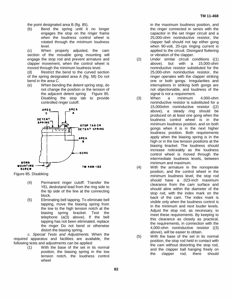
TM 11-468
the point designated area B (fig. 85).(b) Bend the spring until it no longer
engages the stop on the ringer framewhen the loudness control wheel isrotated through the minimum loudnesslevel.
(c) When properly adjusted, the camsection of the movable gong mounting willengage the stop rod and prevent armature andclapper movement, when the control wheel ismoved through the minimum loudness level.(d) Restrict the bend to the curved sectionof the spring designated area A (fig. 58) Do notbend in the area C.(e) When bending the detent spring stop, do
not change the position or the tension ofthe adjacent detent spring Figure 85.Disabling the stop tab to providecontrolled ringer cutoff.
Figure 85. Disabking
(4) Permanent ringer cutoff. Transfer theYEL deskstand lead from the ring side tothe tip side of the line at the connectingblock.
(5) Eliminating bell tapping. To eliminate belltapping, move the biasing spring fromthe low to the high tension notch at thebiasing spring bracket. Test thetelephone (a(3) above). If the belltapping has not been eliminated, replacethe ringer Do not bend or otherwisedistort the biasing spring.
c. Special Tests and Adjustments. When therequired apparatus and facilities are available, thefollowing tests and adjustments can be applied:
(1) With the base of the set in its normalposition, the biasing spring in the lowtension notch, the loudness controlwheel
in the maximum loudness position, andthe ringer connected in series with thecapacitor in the set ringer circuit and a25,000-ohm noninductive resistor, theclapper ball should not tap either gongwhen 90-volt, 20-cps ringing current isapplied to the circuit. Disregard flutteringor vibration of the clapper.
(2) Under similar circuit conditions ((1)above). but with a 15,000-ohmnoninductive resistor substituted for the25,000-ohm noninductive resistor, theringer operates with the clapper strikingone or both gongs. Irregularities andinterruptions in striking both gongs arenot objectionable, and loudness of thesignal is not a requirement.
(3) When a minimum 4,000-ohmnoninductive resistor is substituted for a15,000ohm noninductive resistor ((2)above), a steady ring should beproduced on at least one gong when theloudness control wheel is in theminimum loudness position, and on bothgongs when it is in the next higherloudness position. Both requirementsapply when the biasing spring is in thehigh or in the low tension positions at thebiasing bracket. The loudness shouldincrease noticeably as the loudnesscontrol wheel is moved through theintermediate loudness levels, betweenminimum and maximum.
(4) With the armature in the nonoperateposition, and the control wheel in theminimum loudness level, the stop rodshould have a .023-inch maximumclearance from the cam surface andshould aline within the diameter of thestop rod, with the index mark on theback of the cam. The index mark isvisible only when the loudness control isin the minimum and next louder levels.Adjust the stop rod, as necessary, tomeet these requirements. By keeping tothis clearance as closely as practical,the requirements, in connection with the4,000-ohm noninductive resistor ((3)above), will be easier to obtain.
(5) With the base of the set in its normalposition, the stop rod held in contact withthe cam without distorting the stop rod,and the clapper ball hanging freely onthe clapper rod, there should
82

TM 11-468
be visible clearance between the clapperball and movable gong A, with theloudness control wheel in each loudnesslevel. Adjust the clapper rod to meet thisrequirement.
(6) With the base of the set in its normalposition, the armature in the nonoperateposition, and the clapper ball hangingfreely on the clapper rod, the clearancebetween the clapper ball and the fixedgong should be a minimum .011) inch.If adjustment is necessary to meet thisrequirement, loosen the fixed gongmounting screw that repositions gong B,and retighten the screw.
(7) The parts listed below, which areadjacent to one another in the ringer,should not touch or rub. This mayprevent the free operation of the ringerin each loudness level.
(a) Stop rod and biasing spring bracket.(b) Stop rod and movable gong A.(c) Clapper rod and pole piece.(d) Clapper rod and bridge on ringer frame.
66. Hookswitch Adjustments
Note. The hookswitch assembly ofTelephone TA166/U and TA-236/FT is a sealed unit.Do not perform any adjustment of this assembly. Iftroubleshooting procedures indicate that thehookswitch assembly is dirty or out of adjustment,replace the entire unit.
a. Contact Alinement. Contacts should line up sothat the full width of the contacting surface of each fallswholly within the width of the other mating contact. If thecontacts are not in proper alinement, remove thehookswitch assembly from the mounting and loosen thespring pile-up mounting screws. Shift the springs until thecontacts cross one another at right angles and are asnear the middle of the contacts as possible. Tighten thescrews securely and replace the switch assembly.
b. Operating Spring Tension. Adjust the tensionin the springs so that the springs will meet the followingrequirements:
(1) The operating. springs will return thelever to the full limit of its travel when theplunger or plungers are released slowlyfrom their operated to their unoperatedpositions. If necessary, increase thetension in the springs by bending themcarefully.
(2) Slowly lower the handset on the cradleThe plungers should move downwarduntil the handset rests on one or both ofthe supporting surfaces on themounting. Check this for both positionsof the handset. Gage by sight and touchand, if necessary, decrease the tensionin the springs.
c. Contact Sequence of Operation. Thisadjustment applies only if the hookswitch is equippedwith two sets of contacts, one set of which makes beforethe other set. The contacts of the open set should have aclearance of .006 inch after the other contact set hasmade. Gage by eye; .006 inch is approximately half thethickness of the spring.
d. Contact Follow. This adjustment applies only ifthe hookswitch is equipped with two sets of contacts,one set of which makes before the other set. Thecontacts associated with the contact set which makesfirst should have a follow of approximately one thirty-second inch. Check as follows:
(1) Release the plungers.(2) Insert the .050-inc’i leaf (or .020- and
.030-inch leaves combined) of the feelergage between the lever stud and themake spring of the contact set whichmakes first. With this separation, thecontacts should remain closed. Ifnecessary, carefully bend the spring (gbelow).
e. Contact Separation. This adjustment appliesonly if the hookswitch is equipped with two sets ofcontacts, one set of which makes before the other set.There should be an air gap of .028 inch between thecontacts associated with the contact set which makeslast, when the hookswitch plungers are depressed to thelevel of the handset supporting surfaces. Check with thefeeler gage, and bend the spring carefully, if necessary(g below).
f. Spring Clearance. There should be a minimumclearance of one thirty-second inch between theoperating spring which makes first and the split springthat is associated with the operating spring which makeslast, when the lever is against its stop in the extremedownward position. Gage by eye, and bend the springcarefully, if necessary (g below).
g. Spring Adjusting. No adjustments other thanthose absolutely necessary to meet the foregoingrequirements should be made on the contact springs. Toadjust the springs, use a spring
83

TM 11-468
adjuster (SigC stock No. 6R41266A), and proceed asfollows:
(1) Use the small end of the spring adjuster,and be sure that the full depth of the slotin the tool engages the springs.
(2) To adjust split springs, apply the springadjuster tool close to the spring pile-upand bend the springs slightly.
(3) To aline fingers on the split springs,adjust the top fingers only.
(4) To increase the tension in the operatingsprings, apply the spring adjuster tool ata point close to the contacts, betweenthe contacts and the free end of thesprings, and bow the springs in therequired direction.
(5) To decrease the tension in the operatingsprings, apply the spring adjuster tool atsuccessive points along the springs, andslightly flex them at these points in therequired direction.
(6) Be careful not to kink the springs. Ifsprings are kinked, the entirehookswitch assembly must be replaced.
(7) After making an adjustment on thecontact springs, recheck all springrequirements which might be affected bythe adjustment.
(8) If the springs cannot be adjustedproperly, replace the entire hookswitchassembly.
Section II. CONTACT MAINTENANCE
67. GeneralPitted or built-up contacts, on the hookswitch,
dial, and key equipment contacts, are not necessarily anindication that the contact is no longer useful. Do notreplace the apparatus because of contact erosion,unless one of the contacts of the mating pair hasreached such a state that contact is made on the basemetal to which the contact is welded. In the case of twincontacts, one of each mating pair should be wornthrough to the base metal before replacement isrequired. When necessary, contacts which are not wornthrough to the base metal should be reconditioned. Thisreconditioning should be performed only in a fieldmaintenance shop. In no instance are dials with erodedcontacts to be reconditioned. Replace the dial and sendthe defective dial to afield repair shop.
68. Build-Ups and PitsBuild-ups and pits on contacts result from the action ofelectrical current striking an arc as the contacts makeand break.
a. Pitted Contacts. Progressive stages of contactpitting are illustrated in figure 86. The types of contactsshown are the bar and disk type contacts. The contactson the left side of the illustration are new and wouldrequire no maintenance. The center contacts are pitted,but could be reconditioned. Illustrated on the right side offigure 86 are contacts that are pitted so badly thatcontact would be made with the base metal; thesecontacts should be replaced.
b. Build-Ups on Contacts. Contact build-ups areusually composed of the residue of the mating
Figure 86. Progressive stages of contact pitting (bar anddisk-type contacts).
Figure 87. Build-ups and pits on contacts (bar and disk -type contracts
84
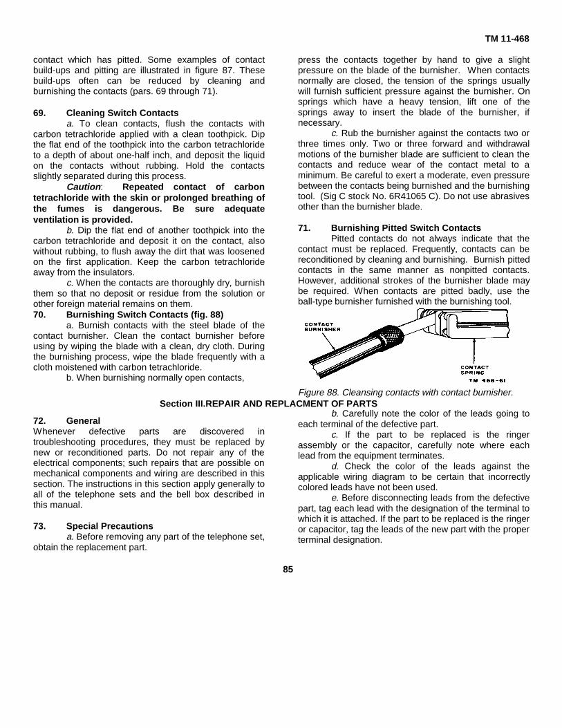
TM 11-468
contact which has pitted. Some examples of contactbuild-ups and pitting are illustrated in figure 87. Thesebuild-ups often can be reduced by cleaning andburnishing the contacts (pars. 69 through 71).
69. Cleaning Switch Contactsa. To clean contacts, flush the contacts with
carbon tetrachloride applied with a clean toothpick. Dipthe flat end of the toothpick into the carbon tetrachlorideto a depth of about one-half inch, and deposit the liquidon the contacts without rubbing. Hold the contactsslightly separated during this process.
Caution: Repeated contact of carbontetrachloride with the skin or prolonged breathing ofthe fumes is dangerous. Be sure adequateventilation is provided.
b. Dip the flat end of another toothpick into thecarbon tetrachloride and deposit it on the contact, alsowithout rubbing, to flush away the dirt that was loosenedon the first application. Keep the carbon tetrachlorideaway from the insulators.
c. When the contacts are thoroughly dry, burnishthem so that no deposit or residue from the solution orother foreign material remains on them.70. Burnishing Switch Contacts (fig. 88)
a. Burnish contacts with the steel blade of thecontact burnisher. Clean the contact burnisher beforeusing by wiping the blade with a clean, dry cloth. Duringthe burnishing process, wipe the blade frequently with acloth moistened with carbon tetrachloride.
b. When burnishing normally open contacts,
72. GeneralWhenever defective parts are discovered introubleshooting procedures, they must be replaced bynew or reconditioned parts. Do not repair any of theelectrical components; such repairs that are possible onmechanical components and wiring are described in thissection. The instructions in this section apply generally toall of the telephone sets and the bell box described inthis manual.
73. Special Precautionsa. Before removing any part of the telephone set,
obtain the replacement part.
press the contacts together by hand to give a slightpressure on the blade of the burnisher. When contactsnormally are closed, the tension of the springs usuallywill furnish sufficient pressure against the burnisher. Onsprings which have a heavy tension, lift one of thesprings away to insert the blade of the burnisher, ifnecessary.
c. Rub the burnisher against the contacts two orthree times only. Two or three forward and withdrawalmotions of the burnisher blade are sufficient to clean thecontacts and reduce wear of the contact metal to aminimum. Be careful to exert a moderate, even pressurebetween the contacts being burnished and the burnishingtool. (Sig C stock No. 6R41065 C). Do not use abrasivesother than the burnisher blade.
71. Burnishing Pitted Switch ContactsPitted contacts do not always indicate that the
contact must be replaced. Frequently, contacts can bereconditioned by cleaning and burnishing. Burnish pittedcontacts in the same manner as nonpitted contacts.However, additional strokes of the burnisher blade maybe required. When contacts are pitted badly, use theball-type burnisher furnished with the burnishing tool.
Figure 88. Cleansing contacts with contact burnisher.
b. Carefully note the color of the leads going toeach terminal of the defective part.
c. If the part to be replaced is the ringerassembly or the capacitor, carefully note where eachlead from the equipment terminates.
d. Check the color of the leads against theapplicable wiring diagram to be certain that incorrectlycolored leads have not been used.
e. Before disconnecting leads from the defectivepart, tag each lead with the designation of the terminal towhich it is attached. If the part to be replaced is the ringeror capacitor, tag the leads of the new part with the properterminal designation.
Section III.REPAIR AND REPLACMENT OF PARTS
85

TM 11-468
f. If the standard wire form is not available, laceall new wiring after installation; keep as close to theoriginal form as possible.
g. Use the properly sized screwdriver to loosenscrew terminals. Do not force the screwdriver blade intoa screw slot too small to accept it.Ioosen the screw just enough to permit the spade lug tobe removed.
h. Be careful to save all screws which mount thepart to be replaced. M1any of these screws are of oddsizes and are not easily replaced.
i. If any of the parts or wiring to be replaced isconnected to solder terminals, follow the proceduresoutlined in TM 11-471, Shop Work.
j. When replacing parts, do not force themounting screws with the screwdriver. If the screw doesnot appear to be traveling evenly into the mounting hole,remove the screw and examine it for traces of stripping.Replace the screw or base plate, as required, if thescrew or mounting holes are stripped too badly. Be surethat any flakes of metal from the screw or screwdriver donot fall into the telephone.
74. Repair of Wiringa. Inside wiring should be repaired only after the
fault location procedures (pars. 55 through 60) havebeen followed. Do not repair internal wiring of telephonesets or key equipments. If defective internal wiring isdiscovered, replace it with wiring of the exact samelength and color coding. If the color coding of the newwiring does not agree with the color coding of thedefective wiring, make a notation to that effect, and placeit under the capacitor mounting bracket, above the circuitlabel. TM 11 474 describes the procedures to befollowed in the repairing and splicing of inside wiring.
b. The causes for damage or deterioration ofwiring should be investigated and, if possible, re(moved.If this is not done, the damage or deterioration will occuragain with time wasted on unnecessary service calls.
75. Replacement Procedures (TP-6 TypeTelephones)Before replacing any parts, disconnect the
telephone at the connecting block. Select a clean, well-lighted working area. loosen the base plate mountingscrews and open the base plate.
a. Replacement of Ringer.(1) TP 6 type telephones except WECo.
302AW-3. loosen and remove the ringer
mounting screws on the underside(outside) of the base plate. Loosen thescrew terminals that are associated withthe ringer leads. Remove the ringercarefully. Place the new ringer in thesame position as the old one. Line upthe ringer mounting holes with the baseplate mounting holes. Lift up the baseplate from the working surface. Drive ineach of the mounting screws fingertight.Turn over the base plate and tighten thescrews with the screwdriver. Connectthe leads to the proper terminals.
(2) Telephone TA-105/FTC. Loosen andremove the ringer mounting screws.Loosen the screw terminals that areassociated with the ringer leads, anddisconnect the leads. Remove the ringercarefully. Place the new ringer in thesame position as the old one. Line upthe ringer mounting holes with the holeson the base plate. Tighten the ringermounting screws with the screwdriver.Connect the ringer leads to the properterminal.
(3) Telephones TP-6-A and TA-166/U andWECo. 320AW-3 telephone. Loosen theringer mounting screw located near theclapper. The other steps in thisparagraph are the same as forTelephone TA- 105/FTC.
b. Replacement of Induction Coil. The mountingof the induction coil varies among the telephonesdescribed in this manual. The WECo. 302AW-3telephone has a more or less typical arrangement for themounting of the induction coil. The procedure describedin (1) through (4) below is for the removal andreplacement of the induction coil of the WECo. 302AW-3. Modify this procedure for other telephones.
(1) Loosen and remove the induction coilretaining screw which is located on theside of the induction coil nearest thehookswitch. Lift up this side of theinduction coil and slide it from under theclamp on the other side.
(2) Loosen the screw terminals and removethe induction coil leads (par. 73e).
(3) Remove the induction coil.(4) Replace the induction coil in a manner
exactly opposite to that followed forremoving the coil.
c. Replacement of Capacitor. The capacitor maybe retained in any one of three ways-by a clamp
86
TM 11-468
which fits over it, by a screw which must be removedfrom the outside of the base plate, or by screws whichmay be removed only after the base plate is opened.Determine the manner in which the capacitor to bereplaced is mounted.
(1) Loosen and remove the retaining screwsand clamp, if any. Loosen the screwterminals that are associated with thecapacitor leads. Be sure that the leadsof the new capacitor are taggedproperly. Remove the capacitor leadsand remove the capacitor.
(2) Mount the new capacitor in the mannerrequired by the telephone. Connect thecapacitor leads to the proper terminals.Tighten the screw terminals.
d. Replacement of Hookswitch. Examine thetelephone carefully to locate the hookswitch mounting-screws. These mounting screws are usually located nearthe screw terminals that are associated with thehookswitc.h. Be sure, before proceeding further, that thescrews decided on are the hookswitch mounting screws.Tag all leads that terminate at the hookswitch with theproper terminal. Loosen all screw terminals anddisconnect the leads. Slide the hookswitch slowly in thesame direction as the hookswitch plunger. After thehookswitch plungers are free of their channels, removethe hookswitch. Carefully slide the new hookswitch intothe proper position. Drive the mounting screws carefullywith the screwdriver. Connect the hookswitch leads tothe proper terminals. Tighten the screw terminals.
e. Replacement of Dial. Loosen the screwterminals associated with the dial. Tag and disconnect allof the dial leads. Loosen and remove the dial retainingscrews. With one hand on the face of the dial, slowlypush the dial from the rear with the other hand until it isfree of the telephone set. Place the new dial in positionfrom the outside of the telephone. Line up the dialmounting holes with the corresponding holes in thecover. Drive the mounting screws carefully with thescrewdriver. Connect the dial leads to the properterminals.
Note The replacement procedures describedin a through c above are the only procedures whichrequire the telephone base plate to be removed.Perform all other replacement procedures with thetelephone assembled.
f. Replacement of Transmitter or Receiver.Unscrew the transmitter or receiver cap located on the
handset. (When replacing the transmitter or receiver ofTelephone TA-105/FTC, remove the transmitterassembly from the telephone; when replacing thereceiver, unscrew the receiver cap.) Remove thedefective part; insert the new part and screw on the cap.
g. Replacement of Handset. Unscrew thetransmitter cap and remove the transmitter. Loosen thethree screw terminals that are associated with thetransmitter contacts. Disconnect all of the leads, andremove the stay cord after loosening or removing thestay-hook retaining screw. Gently pull the handset cordaway from the handset. Gently push the handset cordthrough the entrance on the new handset until the threeleads are into the handset a sufficient distance so thatthey can be connected to the proper terminals. Fastenthe stay cord, and connect the leads to the properterminals. Replace the transmitter and screw on the cap.
76. Removal and Replacement of DialEscutcheon Assembly
Note. These instructions apply only to Dial TA-45/GT.No special instructions are necessary to remove andreplace the dial escutcheon assembly of dial TA-45B/GT.
a. Insert the escutcheon tool (Sig C stock No.4D26917) under the escutcheon ring at the digit 5 fingerhole (A, fig. 89). Press the tool down against the lockinglever under the card. Move the tool counterclockwise tothe digit 6 finger hole (B, fig. 89). This unlocks the cardassembly. With the tip of the tool, lift the escutcheon ringat the digit 6 finger hole and remove the card assembly(B, fig. 89).
b. The escutcheon ring, transparent cover,number card, and number-card clamping plate comprisethe card assembly. Release the components by turningthe assembly face down and slightly rotating the notchedclamping plate in a counterclockwise direction. Note therelative position of the parts as they are removed. Theymust be assembled in the reverse order of their removal.
c. In reassembling the components of the cardassembly, place the transparent cover in the escutcheonring first so that it will protect the dial card. Next place thedial card in the ring; place the dial card clamping plateover the number card last. Turn the clamping plate in aclockwise direction to engage its tongue which locks theassembly.
87

TM 11-468
Figure 89. Removing escutcheon ring and dial card from dial.
77. Replacement Procedures for Telephone SetTA-2361FT
a. Housing Assembly.(1) Remove the handset from its cradle.(2) Back out the two captive screws at both
ends of the outer surface of the baseplate until the housing assembly isreleased from the base plate.
(3) Remove the housing assembly from thebase plate. The housing assembly isbrittle and should be handled carefully.
(4) Install the new assembly by reversingthe procedures given in (2) and (3)above.
(5) Replace the handset in its cradle.b. Handset Cord.
(1) Remove the transmitter cap.(2) Pluck out the transmitter element and
the plastic cup.(3) Disconnect the BLK and RED cord leads
from the cup terminals.(4) Remove the receiver cap.(5) Remove the receiver element.(6) Disconnect the two WH cord leads from
the receiver element terminals.(7) Attach a short length of string to one of
the WH leads (drag line).(8) With long-nosed pliers, release the cord
grommet from the groove in the anchorpost at the transmitter element cavity(fig. 37).
(9) Withdraw the cord from the handle.Leave the string in the handle cavity.
(10) Disconnect the cord leads from theterminals at the network terminal board.
(11) Pass the new cord leads through theopening at the transmitter end of the
handle until the approaching end of thegrommet just enters the handle.
(12) Attach the drag string to the tipped endsof the two WH leads, and draw themthrough the handle cavity toward thereceiver end of the handle until the leadscan be connected to the receiver unit.
(13) Connect the two WH leads securely tothe receiver unit terminals, and place theunit into its cavity.
(14) Place the receiver cap and secure ithand-tight. Do not use any tool to tighteneither cap on a handset handle.
(15) With long-nosed pliers, draw thegrommet into the transmitter cavity untilthe grommet groove can be pressed intothe anchor post groove. Press thegrommet into the anchor post groove.
(16) Connect the RED and BLK leadssecurely to the cup terminals.
(17) Insert the cup into the transmitter cavitywith the boss on the cup fitted into thegroove in the cavity wall.
(18) Place the transmitter element in the cup,replace the cap, and secure it hand-tight.
(19) Connect the cord leads at the networkterminal board.
c. Deskstand Cord.(1) Disconnect the cord leads at the network
terminal board.(2) Disengage the stayband hook from the
base slot.(3) Install the new cord by reversing the
procedures given in (1) and (2) above.d. Ringer.
(1) Note the network terminals to which thefour ringer leads are connected.
88

TM 11-468
(2) Remove the ringer leads from thenetwork terminals.
(3) Back out the two captive mountingscrews that attach the ringer frame tothe frame mounting brackets until theyclear the brackets.
(4) Raise up the gong end of the ringerframe slightly and draw the ringer awayfrom the switch bracket until the locatingpin becomes free from the switchbracket grommet.
(5) Replace the ringer by reversing theprocedure given in (2) through (4)above.
e. Ringer Coil.(1) Note the network terminals to which the
four ringer leads are connected and theposition of the coil on the ringer core.
(2) Remove the ringer leads from thenetwork terminals.
(3) Remove the two mounting screws thatattach the laminated ringer core. to theringer frame.
(4) Withdraw the core laminations from thecoil spool.
(5) Lift the coil from the frame.(6) Place the new coil in the frame in the
exact position held by the removed coil.(7) Slide the core laminations through the
center of the coil spool and arrangethem so that the holes in the laminationsare aligned and are in line with the ringerframe mounting holes.
(8) Place the two core mounting screws andfasten them securely.
(9) Connect the four ringer leads, accordingto color code, to the network terminalsfrom which the replaced leads havebeen removed.
f. Ringer Mounting Bracket.(1) Remove the ringer from the set (d
above).(2) Note that there are two mounting
brackets and that they differ in design.(3) Remove the two rivets that attach the
bracket to the base plate.(4) Place the new bracket in position,
according to type; with two suitablerivets, attach the bracket to the baseplate.
(5) Replace and fasten the ringer.g. Gongs.
(1) A gong is mounted over an associatedresonator and attached to a gongmounting post with a screw and washer.
(2) There are two gongs. The movablegong, with the designation A stamped onits outer surface adjacent to its mountinghole, is mounted on the movable part ofthe ringer assembly directly above theringer coil. The other gong (fixed) hasthe designation B. The gongs are notinterchangeable.
h. Dial (fig. 41).(1) Note the network terminals to which the
four dial leads are connected.(2) Remove the dial leads from the network
terminals.(3) Back out the two diametrically opposite
mounting screws about 2 turns and theremaining screw about 3 turns from thedial mounting bracket.
(4) Raise the dial upward from the shortbracket post, and withdraw the dial fromthe bracket.
(5) Place the new dial in the mountingbracket, fasten it securely, and connectthe dial leads to the same networkterminals from which the replaced leadswere removed.
i. Dial Protective Housing.(1) Remove the dial from the dial mounting
bracket.(2) Withdraw the two housing mounting
screws from the dial mounting plate.(3) Raise the housing straight away from
the mounting plate.(4) Position the new housing, with the
curved corner of the housing fittedclosely to the curved corner of the dialspring block, the remainder of the openedge of the housing fitted to the blockgroove, and the mounting holes alinedwith the dial plate mounting holes.
(5) Replace the housing mounting screwsand fasten them securely.
(6) Replace the dial in its mounting bracketand fasten it securely.
j. Dial Spring Block.(1) Note the network terminals to which the
four dial leads are connected.(2) Remove the dial leads from the network
terminals.(3) Remove the dial from its mounting (h(3)
and (4) above).(4) Remove the dial protective housing (i(2)
and (3) above).
89
TM 11-468
(5) Note carefully the relative positions ofthe pawl finger with springs A and B (fig.55).
(6) Back out the two spring block fastenersuntil the block is detached from the dialmounting.
(7) Rotate the finger wheel enough to causethe pawl finger to move to a positionagainst the pawl-finger stop.
(8) Lift the spring block upward from the dialmounting and in a slightly forwarddirection to prevent snagging the hookon spring B on the pawl finger stop.
(9) Place the new spring block assemblywith each of its components in its properposition, and fasten it securely to the dialmounting.
(10) Spin the dial five times through its fulltravel distance and observe that itsoperation meets all requirements.
(11) Replace the protective housing over thedial mechanism, replace the dial on itsmounting, and fasten both securely.Check for the presence of the gaskettubing around the outer edge of the dial.
(12) Connect the dial leads to the samenetwork terminals from which thereplaced leads were removed.
k. Dial Finger Stop.(1) Remove the dial from its mounting
bracket.(2) Back out the finger stop fastening screw
enough to release the stop.(3) Lift the finger stop away from the front
face of the dial.(4) Place the new finger stop and fasten it
securely.(5) Replace the dial on its mounting bracket
and fasten it securely.l. Dial Finger Wheel.
(1) Remove the dial from its mountingbracket.
(2) Remove the station number card holderassembly from the dial wheel.
(3) Remove the dial finger stop (k(2) and (3)above).
(4) With a suitable 7/8-inch wrench, removethe finger wheel retaining nut from thedial shaft.
Caution: Hold down on the fingerwheel while removing or looseningthe finger-wheel nut to prevent thehub retainer from leaving the shaft;otherwise the hub assembly andmotor spring may
jump out of their proper operatingposition, which would require areplacement of the dial.
(5) Note that the cupped surface of thefinger-wheel washer is placed againstthe finger wheel; then remove thewasher.
(6) Note the position of the 1 and 0 dialopenings with respect to the rectangular,finger stop in the dial number plate.Then remove the finger wheel.
(7) Place the new finger wheel on the shaftand reassemble the dial components byreversing the procedure for disassembly.
m. Dial Number Plate.(1) Remove the dial from its mounting
bracket (h(3) and (4) above).(2) Remove the finger stop (k(2) and (3)
above).(3) Remove the station number card
assembly from the finger wheel.(4) Remove the finger wheel (1(4) through
(6) above).(5) Remove the three mounting screws from
the dial number plate.(6) Carefully note the position of the dial
number plate on the dial mounting.(7) Lift the number plate away from the dial
mounting.lace the new number plate on the dialmounting in the same position as thatpreviously occupied by the replacedplate.
(9) Place and secure the number platemounting screws.
(10) Reassemble the dial components byreversing the disassembly procedure.
n. Dial Mounting Bracket.(1) Remove the dial from its mounting
bracket.(2) Remove the three fastening rivets that
attach the bracket to the base plate.(3) Place and rivet the new bracket to the
base plate.(4) Replace and fasten the dial on the
bracket.o. Switch Protective Housing.
(1) With the finger and thumb, press inwardon the sides of the housing.
(2) Withdraw the bottom end of the housingaway from the switch assembly.
(3) Remove the housing.(4) When replacing the housing, insert the
vertical surface of the angular tangcomponent of the housing into the slot inthe
90
TM 11-468
switch assembly bracket, adjacent to thetop end of the switch assembly.
(5) With the finger and thumb, press inwardon the sides of the housing, and guidethe housing into place in the switchassembly bracket.
p. Switch Assembly.(1) Remove the dial from its mounting.(2) Note the network terminals to which the
seven switch leads are connected.(3) Disconnect or unsolder, as required,
these leads at the newtork terminalboard.
(4) Remove the three fastening rivets thatattach the assembly to the base plate.
(5) Position the new switch assembly, andrivet it fast to the base plate.
(6) Connect or solder the switch leads to thesame terminals as were occupied by theremoved leads.
(7) Replace the switch protective housing(o(4) and (5) above).
q. Network Assembly.(1) Remove the dial from its mounting
bracket.(2) Disconnect or unsolder, at the network
terminal board, all wires and leads thatterminate at the board.
(3) Remove the three rivets that attach thenetwork assembly to the base plate.
(4) Remove the assembly.(5) Place the new assembly, and rivet it fast
to the base plate.(6) Reconnect all wires and leads,
previously removed or unsoldered, at theterminal board (fig. 67).
(7) Replace the dial on its mounting bracketand fasten it securely.
r. Replacement of Station Dial with Dial Blank (fig. 34).(1) Remove the dial as outlined in h(2)
through (4) above.
(2) Transfer the GY-WH switch lead fromterminal F to terminal RR at the networkterminal board.
(3) Place the dial blank in the space in thehousing assembly previously occupiedby the dial.
(4) Invert the housing and adjust the blankuntil the barb of the arrow points towardthe front of the housing. The arrow andthe word FRONT are molded on theinside surface of the blank.
(5) Place the dial-blank mounting clampinside the housing, with its flangedsurface toward the dial blank and withthe circular section of each mountinghole directly over the heads of themounting screws.
(6) Pass the mounting clamp down and overthe screw heads and adjust the clampuntil its two locating ears fit into the twoslots in the bead that circles the edge ofthe dial opening in the housingassembly.
(7) While holding the assembly in thesecured position, rotate the dial blankuntil the screw shanks prevent anyfurther rotation of the blank.
(8) Tighten the two screws securely.(9) Place the station number card assembly
on the dial blank.s. Friction Pad.
(1) Release the pad from the base plate byremoving the single rivet that attachesthe pad to the plate.
(2) Place the new pad in position with itstwo bosses alined with the two smallholes in the base plate.
(3) With a suitable rivet, secure the pad tothe plate.
Note. Observe that the dimensionsof the rivet used to attach the friction pad(.166 inch in diameter by Ci-inch long)do not match the rivet used to attach theother rivet-attached set components,which are .136 inch in diameter by W)-inch long.
Section IV. FINAL TESTING
78. GeneralAfter completing all troubleshooting and repairs
and adjustments, the telephone set should be final-tested to determine that it is in good working order. Finaltesting is divided into two parts-visual examination andperformance testing.
79. Visual Examinationa. Wiring.
(1) Examine all connections for tightness.(2) Examine all splices for adequate
strength and proper insulation.
91
TM 11-468
(3) Check all new internal wiring forexcessive length as compared to oldwiring.
(4) Check all new inside wiring to be certainthat there are no points where wearingof insulation or straining of wiring willoccur.
b. Internal Components.(1) Check all new parts for tightness of
mounting.(2) Check all leads for proper termination.(3) Make certain that no small pieces of
insulation, wiring, or solder have fallenbetween the ringer armature and thecoils.
80. Performance TestingThere is only one test for proper performance of
the telephone set. The telephone must be tested underactual operating conditions.
a. Remove the handset from the cradle. Note ifthe dial tone is received or the operator answers.
b. Dial or call the number of the test desk or testboard.
c. Note if transmission and reception aresatisfactory.
d. Instruct the test man to ring on the line andreplace the handset on the cradle.
e. Note if the ringing signal is of satisfactoryaudibility.
92
TM 11-468CHAPTER 5
SHIPMENT AND LIMITED STORAGE AND DEMOLITION TO PREVENT ENEMY USE
81. Removing from Servicea. Remove the line fuses from the substation
protector.b. Remove the cover from the connector block.c. Disconnect the inside house wire from the
connector block and unscrew the block from itsmounting.
d. Replace the cover on the connector block.Leave the deskstand cord fastened inside the connectorblock to prevent loss.
e. With the handset in the cradle, wrap thehandset and deskstand cord neatly around the base ofthe telephone and the handset.
82. RepackingNote. The circumstances involved in
shipment and storage vary. The followinginstructions are recommended as a guide forpreparing a common battery telephone fortransportation and storage. Whenever possible, usethe original packaging materials.
a. Cushion the telephone on all surfaces withsome type of cushioning material such as cell material,pads fabricated of corrugated fiberboard, or excelsior.This will absorb the shock of impact normallyencountered in handling and during transit.
b. If possible, place a dehydrating agent, such assilica gel, inside the cushioning material.
c. Place the cushioned equipment in a close-fitting corrugated fiberboard box. Seal the entire closurewith gummed paper tape. Blunt the corners of the box.
d. Place the boxed equipment in a water
vaporproofed barrier. Extract the air and heat-seal thebarrier.
e. Place the barrier-wrapped box in a secondclose-fitting corrugated fiberboard box. Seal the box withwater-resistant tape or adhesive.
83. Methods of DestructionThe demolition procedures outlined below will be used toprevent the enemy from using or salvaging theequipment. Demolition of the equipment will beaccomplished only upon order of the commander.
a. Smash. Smash the handset shell and thetransmitter and receiver units. Smash the housingassembly, capacitors, induction coil, dial, hookswitch,connector block, hand generator (EE-91), and the ringer;use sledges, axes, handaxes, pickaxes, hammers,crowbars, or other heavy tools.
b. Cut. Cut handset cord, deskstand cord,internal wiring, and spring terminals in the transmitterand receiver mounting; use axes, handaxes, diagonalpliers, side-cutting pliers, or machetes.
c. Burn. Burn the plastic housing assembly,wiring, ringer coils, induction coil, handset cord,deskstand cord, and handset shell; use gasoline,kerosene, oil, flame throwers, or incendiary grenades.
d. Explosives. If explosives are necessary, usefirearms, grenades, or TNT.
e. Disposal. Bury or scatter the destroyed partsin slit trenches, foxholes, or other holes in the ground, orthrow them into streams.
f. Destroy. Destroy everything.
93
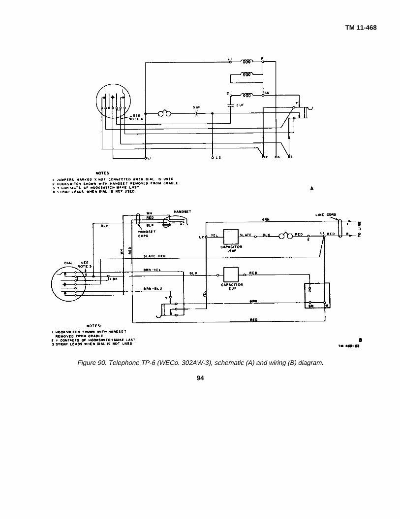
TM 11-468
Figure 90. Telephone TP-6 (WECo. 302AW-3), schematic (A) and wiring (B) diagram.
94
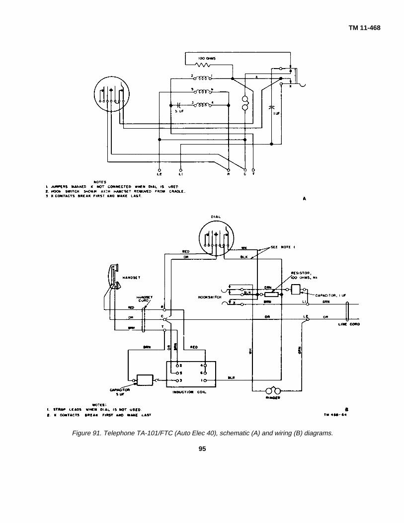
TM 11-468
Figure 91. Telephone TA-101/FTC (Auto Elec 40), schematic (A) and wiring (B) diagrams.
95

TM 11-468
Figure 92. Telephone TA-LOS/FTC (Kellogg 9 BAX). schematic (A) and wiring (B) diagrams.
96
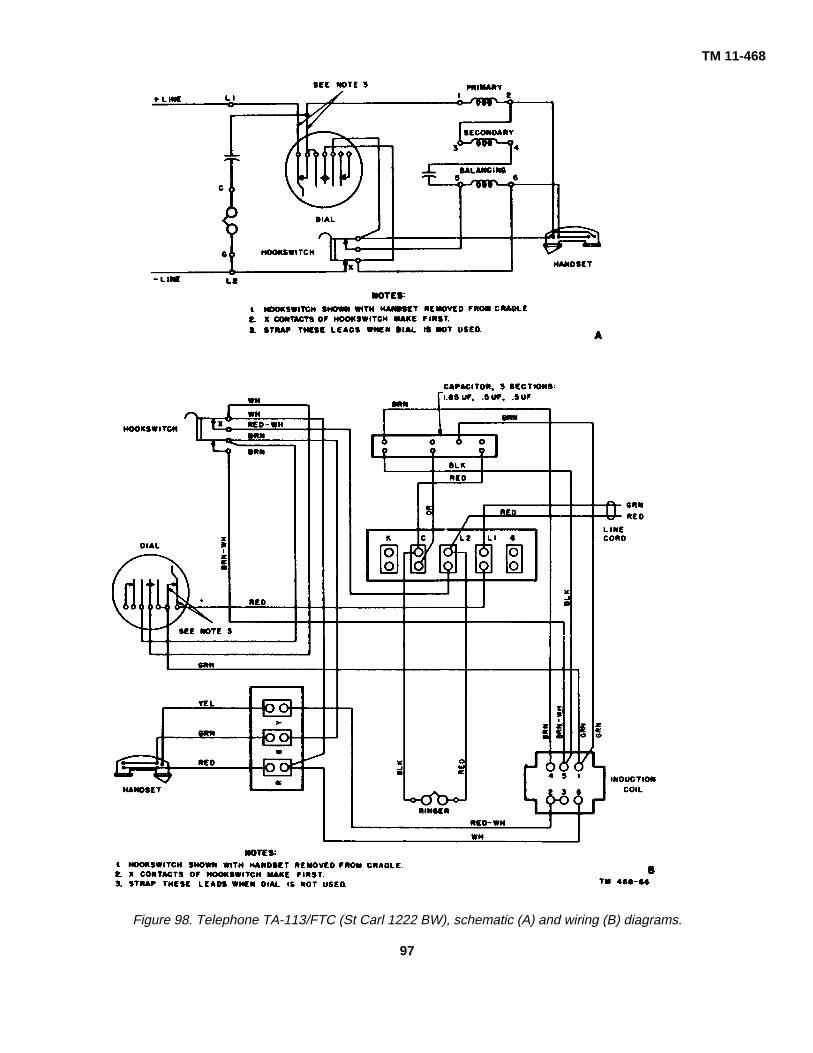
TM 11-468
Figure 98. Telephone TA-113/FTC (St Carl 1222 BW), schematic (A) and wiring (B) diagrams.
97

TM 11-468
Figure 94. Telephone TP-6 (St Carl 1242 WA), schematic (A) and wiring (B) diagrams.
98

TM 11-468
Figure 96. Telephone TP- 6 (North Elec. MFG 3H4SL and H-600SL), schematic (A) and wiring (B) diagrams.
99

TM 11-468
Figure 96. Telephone TA-107/FTC, schematic (A) and wiring (B) diagrams.
100

TM 11-468
Figure 97. St. Carl 1212 ABZ telephone, schematic (A) and wiring (B) diagrams.
101

TM 11-468
Figure 98. Telephone TA-105/FTC, schematic (A) and wiring (B) diagrams.
102
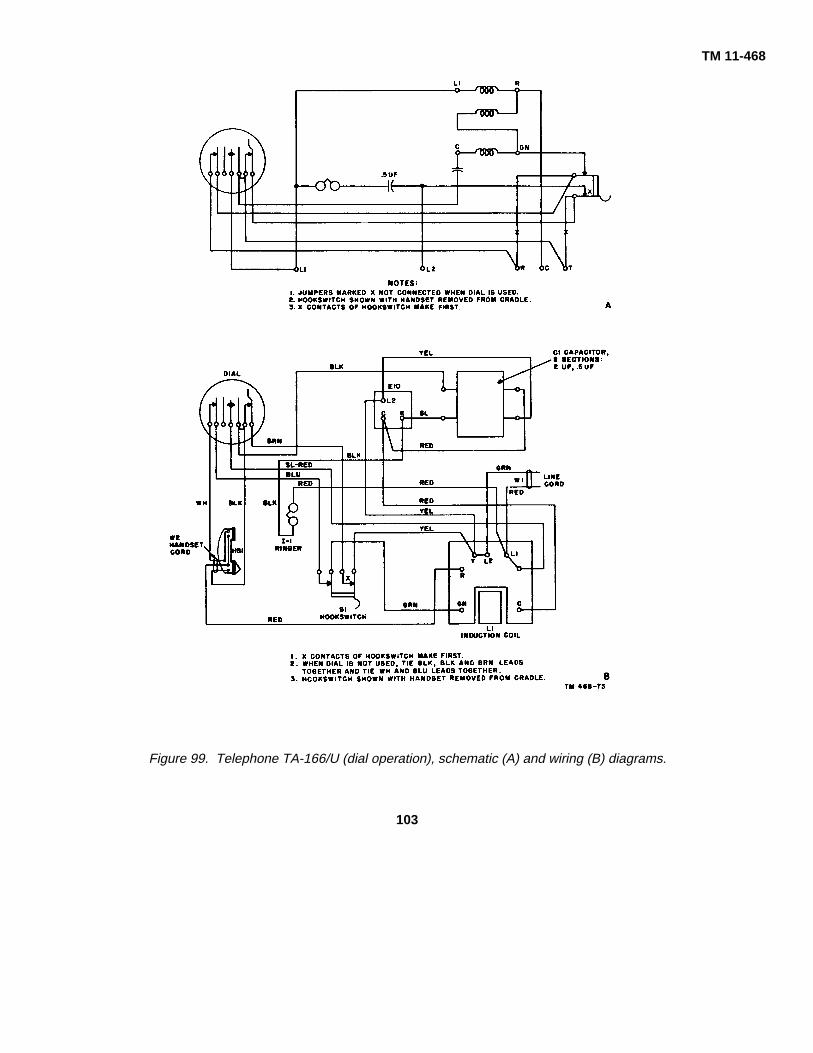
TM 11-468
Figure 99. Telephone TA-166/U (dial operation), schematic (A) and wiring (B) diagrams.
103

TM 11-468
Figure 101. Wiring diagram for Telephone Box EE-91.
104

TM 11-468
Figure 102. Telephone TA-212/U, wiring diagram.
105
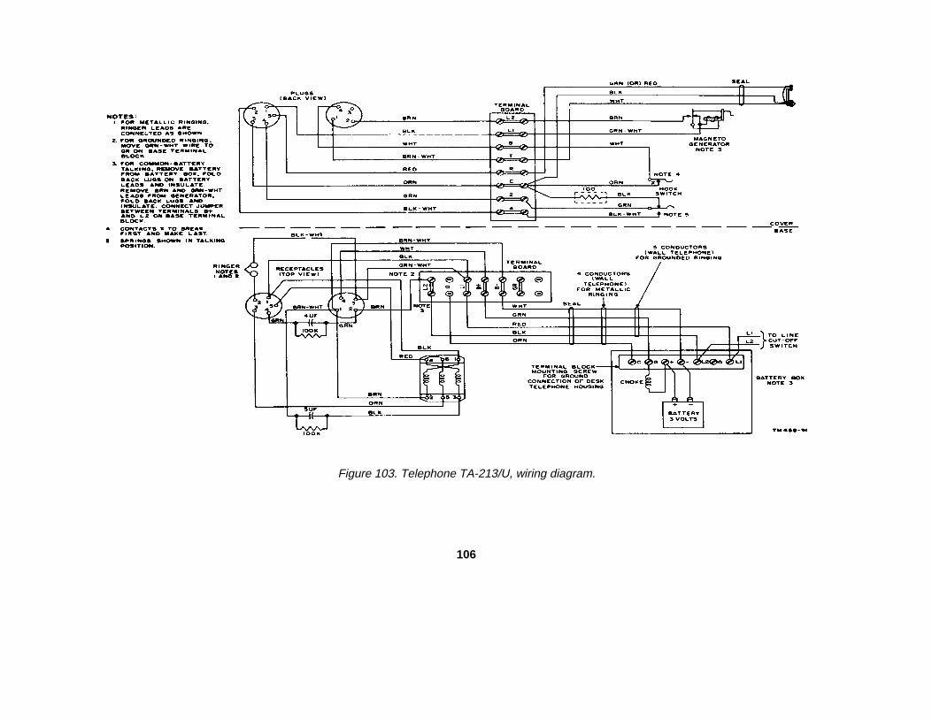
Figure 103. Telephone TA-213/U, wiring diagram.
106

INDEX
Para- Para-Adjustments: graph Page Description-Continued graph Page
Dial, TA-236/FT__.............................63c 79 Receiver, TA-236/FT ...............................10e 25Dial, TA-45(*)/GT ..............................63b 79 Ringer, TA-236/FT...................................10f 25Hookswitch........................................66 83 Set components, TA-236/FT ...................10 24Ringer, TA-236/FT ............................65 81 St. Carl 1212ABZ telephone....................3d 11Ringer, TP-6......................................64 79 Switch assembly, TA-236/FT ..................10i 31
Antisidetone circuit: Telephone:TA-236/FT.........................................- 38 51 TA-107/FTC ......................................3c 11TP-6-A...............................................21 41 TA-166/U ..........................................5 13
TA-212/U ..........................................11 31Base plate assembly, TA-213/ .............................................12 33
scription................................................10b 24 TP-6-A ..............................................3b 11Bell box, description ................................13 33 Telephone Box EE-91 .............................6 13Blocks: Telephone Set TA-105/FTC ....................4 11
Connecting........................................14 35 Telephone Set TA-236/FT.......................9 16Protector ...........................................15c 37 Transmitter, TA-236/FT ...........................10d 24
Bridle wire, opens....................................57d 73 Desk-type telephones.................................3 3Build-ups and pits, contacts ....................68 84 Destruction, methods..................................83 93Build-ups on contacts ..............................68b 84 Dial:Burnishing, contact..................................70 85 TA-45(*)/GT, description...................8 15Capacitors, testing, TP-6-A .....................53 68 TA-45/GT, lubrication........................45b 59Chart, Troubleshooting: TA-45B/GT, lubrication .....................45c 59
TA-236/FT 48b 63 TA-236/FT, description .....................10g 29TP-6-A 48a 61 TA-236/FT, theory.............................24 42
Circuit: Testing 63a 79Antisidetone, TP-6A..........................21 41 Dial adjusting:Ringing, TP-6-A ................................20 41 Dial, TA-45(*)/GT ..............................63b 79Transmitter and receiver, TP-6-A .....19 40 Dial, TA-236/FT ................................63c 79
Cleaning ..................................................42e 58 Dial escutcheon, replacement ....................76 87Cleaning switch contacts.........................69 85 Dialing circuit, TA-236/FT:Clearing shorts ........................................58c 74 Schematic .........................................36 50Components, TA-236/FT.........................10 24 Wiring................................................37 50Connecting blocks ...................................14 35 Dropwire:Contacts: Opens ...............................................57d 73
Build-ups ...........................................68b 84 Preventive maintenance ...................42a 55Burnishing .........................................70 85 Equalizer, theory.........................................25d 43Maintenance .....................................67 84 Equipment, Tool:Pitted.................................................68a 84 TE-33 ................................................39a 53Switch, cleaning ................................69 85 TE-49 ................................................39b 53
Continuity test: TE-73 ................................................39c 53TA-236/FT.........................................61 77 Examination, visual.....................................79 91Telephone, general ...........................49 65 Fault location ..............................................46-61 60-77TP-6-A...............................................50 66 Faults, line, location....................................56 72
Crosses Forms .........................................................2 3Line ...................................................60 77 Fuses, protector..........................................15e 37Telephone set ...................................55 70
Ground lead, opens ....................................57c 73Description:
Baseplate assembly, TA-236/FT ......10b 24 Handsets:Bell box .............................................13 33 Description 8 15Dial, TA-236/FT.................................10g 29 TA-236/FT ..................................................10c 24Dial, TA-45(*)/GT ..............................8 15 TP-6............................................................8b 15Handset: TS-12-F ......................................................8a 15TA-236/FT.........................................10c 24 Hookswitch adjustments ............................66 83TP-6 type ..........................................7b 15 Inside wire, opens.......................................57d 73TS-12-F.............................................7a 15 Inside wiring, preventive maintenance’s.....42c 55Network, TA-236/FT .........................10h 31 Instructions, lubricating...............................45 58
107

Para- Para-Line: graph Page Ringer circuit: graph Page
Crosses ..................................................60 77 TA-236/FT, theory.................................. 28 46Faults .....................................................56 72 TP-6-A, testing ....................................... 52 68Opens .....................................................57 72 TP-6-A, theory........................................ 20 41Opens, locating.......................................576 72 Ringer, TA-236/FT:Shorts .....................................................58 73 Description ............................................. 10f 25
Locating crosses, TP-6A................................55 70 Theory.................................................... 26 46Locating line faults .........................................56 72Locating line faults .........................................56 72 Service, removing from..................................... 81 93Lubricants ......................................................44 58 Set components, TA-236/FT............................. 10 24Lubricating instructions ..................................45 58Lubricating instructions ..................................45 58 Short-circuits, telephone sets, test ................... 54 68Lubrication:Lubrication: .................................................... Shorts, line........................................................ 58 73
Dial, TA-45/GT........................................45b 59 Substation protectors........................................ 15 37Dial, TA-45B/GT .....................................45c 59 Switch contacts, cleaning ................................. 69 85General...................................................43 58 Switch, TA-236/FT, description......................... 10i 31
Maintenance:Contact ...................................................67 84 Telephone Box E-91, description...................... 6 13Preventive, definition ..............................41 54 Telephone, description:Preventive, definition ..............................41 54 St. Carl, 121.2 ABZ ................................ 3d 11Preventive techniques ............................42 55 TA-107/FTC ........................................... 3 11
Methods of destruction ..................................83 93 TA-166/U................................................ 5 13TA-166/U................................................ 5 13
Network assembly, TA-236/FT: ..................... TP-6 ....................................................... 3a 3Description..............................................10h 31 Theory............................................. 16 40Theory ....................................................25 43 Telephone set:
Opens: ........................................................... -Continuity test ....................................... 49 65Line.........................................................57 72 Desk-type, description ........................... 3 3Telephone sets .......................................51 68 Opens .................................................... 51 68
Preventive maintenance ........................ 42d 55Performance testing.......................................80 92 Short-circuit tests ................................... 54 68Pits, build-ups and .........................................68 84 Telephone Set TA-236/FT:Pitted contacts ...............................................68a 84 Antisidetone circuit ................................. 38 51Pitted contacts, burnishing ............................71 85 Continuity test ........................................ 61 77Preventive maintenance, definition ................41 54 Description ............................................. 9 16Preventive maintenance techniques: ............. Dial, theory of......................................... 24 42
Drop wire ................................................42a 55 Dialing circuit, schematic ....................... 36 50Inside wire ..............................................42c 55 Dialing circuit, wiring .............................. 37 50Protectors ...............................................426 55 Network assembly, theory...................... 25 43Telephone set .........................................42d 55 Receiver circuit:
Protectors: ..................................................... Dial schematic ................................ 33 49AR-6 and AR-6-A...................................15b 37 Dial wiring ....................................... 35 49Blocks .....................................................15c 37 Manual schematic ........................... 32 48Fuses......................................................15e 37 Manual wiring.................................. 34 49Preventive maintenance .........................426 55 Theory............................................. 23 42
Receiver circuit, TA-236/FT: .......................... Replacement procedures ....................... 77 88Dial, schematic .......................................33 49 Ringer adjustment.................................. 65 81Dial, wiring ..............................................35 49 Ringer circuit, theory .............................. 28 46Manual, schematic..................................32 48 Ringer, theory ........................................ 26 46Manual, wiring.........................................34 49 Transmitter circuit:
Receiver, TA-236/FT, description ..................10e 25 Dial, wiring, theory .......................... 31 48Receiver, TA-236/FT, theory..........................23 42 Manual, schematic, theory .............. 29 46Removing from service ..................................81 93 Manual, wiring, theory..................... 30 47Repacking......................................................82 93 Transmitter, theory................................. 22 42
Telephone Set TA-212/U, description............... 11 31Repair: ........................................................... Telephone Set TA-213/U, description............... 12 33
General...................................................72 85 Telephone TP-6-A:Special precautions ................................73 85 Continuity testing ................................... 50 66Wiring .....................................................74 86 Cross ..................................................... 55 70
Replacement:................................................. Description ............................................. 36 11Dial escutcheon ......................................76 87 Opens .................................................... 51 68Procedures for TA-236/FT ......................77 88 Replacement procedures ....................... 75 86Procedures for TP-6 type........................75 86 Ringer circuit. Testing ........................... 52 68
Ringer adjustments: ....................................... Short-circuit tests ................................... 54 68TA-236/FT...............................................65 81 Testing capacitors.................................. 53 68TP-6........................................................64 79 Theory.................................................... 18-21 40,41
108
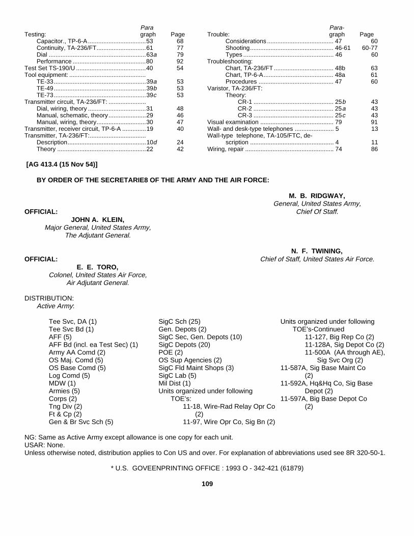
Para Para-Testing: graph Page Trouble: graph Page
Capacitor., TP-6-A ..................................53 68 Considerations ....................................... 47 60Continuity, TA-236/FT.............................61 77 Shooting................................................. 46-61 60-77Dial .........................................................63a 79 Types ..................................................... 46 60Performance ...........................................80 92 Troubleshooting:
Test Set TS-190/U .........................................40 54 Chart, TA-236/FT ................................... 48b 63Tool equipment: ............................................. Chart, TP-6-A......................................... 48a 61
TE-33......................................................39a 53 Procedures ............................................ 47 60TE-49......................................................39b 53 Varistor, TA-236/FT:TE-73......................................................39c 53 Theory:
Transmitter circuit, TA-236/FT: ...................... CR-1 ............................................... 25b 43Dial, wiring, theory ..................................31 48 CR-2 ............................................... 25a 43Manual, schematic, theory......................29 46 CR-3 ............................................... 25c 43Manual, wiring, theory.............................30 47 Visual examination ........................................... 79 91
Transmitter, receiver circuit, TP-6-A ..............19 40 Wall- and desk-type telephones ....................... 5 13Transmitter, TA-236/FT:................................. Wall-type telephone, TA-105/FTC, de-
Description..............................................10d 24 scription ................................................. 4 11Theory ....................................................22 42 Wiring, repair .................................................... 74 86
[AG 413.4 (15 Nov 54)]
BY ORDER OF THE SECRETARIE8 OF THE ARMY AND THE AIR FORCE:
M. B. RIDGWAY,General, United States Army,
OFFICIAL: Chief Of Staff.JOHN A. KLEIN,
Major General, United States Army,The Adjutant General.
N. F. TWINING,OFFICIAL: Chief of Staff, United States Air Force.
E. E. TORO,Colonel, United States Air Force,
Air Adjutant General.
DISTRIBUTION:Active Army:
Tee Svc, DA (1) SigC Sch (25) Units organized under followingTee Svc Bd (1) Gen. Depots (2) TOE’s-ContinuedAFF (5) SigC Sec, Gen. Depots (10) 11-127, Big Rep Co (2)AFF Bd (incl. ea Test Sec) (1) SigC Depots (20) 11-128A, Sig Depot Co (2)Army AA Comd (2) POE (2) 11-500A (AA through AE),OS Maj. Comd (5) OS Sup Agencies (2) Sig Svc Org (2)OS Base Comd (5) SigC Fld Maint Shops (3) 11-587A, Sig Base Maint CoLog Comd (5) SigC Lab (5) (2)MDW (1) Mil Dist (1) 11-592A, Hq&Hq Co, Sig BaseArmies (5) Units organized under following Depot (2)Corps (2) TOE’s: 11-597A, Big Base Depot CoTng Div (2) 11-18, Wire-Rad Relay Opr Co (2)Ft & Cp (2) (2)Gen & Br Svc Sch (5) 11-97, Wire Opr Co, Sig Bn (2)
NG: Same as Active Army except allowance is one copy for each unit.USAR: None.Unless otherwise noted, distribution applies to Con US and over. For explanation of abbreviations used see 8R 320-50-1.
* U.S. GOVEENPRINTING OFFICE : 1993 O - 342-421 (61879)
109


PIN: 010422-000

This fine document...
Was brought to you by me:
Liberated Manuals -- free army and government manuals
Why do I do it? I am tired of sleazy CD-ROM sellers, who take publicly available information, slap “watermarks” and other junk on it, and sell it. Those masters of search engine manipulation make sure that their sites that sell free information, come up first in search engines. They did not create it... They did not even scan it... Why should they get your money? Why are not letting you give those free manuals to your friends?
I am setting this document FREE. This document was made by the US Government and is NOT protected by Copyright. Feel free to share, republish, sell and so on.
I am not asking you for donations, fees or handouts. If you can, please provide a link to liberatedmanuals.com, so that free manuals come up first in search engines:
<A HREF=http://www.liberatedmanuals.com/>Free Military and Government Manuals</A>
– SincerelyIgor Chudovhttp://igor.chudov.com/
– Chicago Machinery Movers