submarine landslides-advances and challenges.pdf
DESCRIPTION
landslideTRANSCRIPT
Submarine landslides: advances and challenges1
Jacques Locat and Homa J. Lee
Abstract: Due to the recent development of well-integrated surveying techniques of the sea floor, significant improve-ments were achieved in mapping and describing the morphology and architecture of submarine mass movements. Ex-cept for the occurrence of turbidity currents, the aquatic environment (marine and fresh water) experiences the sametype of mass failure as that found on land. Submarine mass movements, however, can have run-out distances in excessof 100 km, so their impact on any offshore activity needs to be integrated over a wide area. This great mobility ofsubmarine mass movements is still not very well understood, particularly for cases like the far-reaching debris flowsmapped on the Mississippi Fan and the large submarine rock avalanches found around many volcanic islands. A majorchallenge ahead is the integration of mass movement mechanics in an appropriate evaluation of the hazard so thatproper risk assessment methodologies can be developed and implemented for various human activities offshore, includ-ing the development of natural resources and the establishment of reliable communication corridors.
Key words: submarine slides, hazards, risk assessment, morphology, mobility, tsunami.
Résumé : Le développement récent de techniques de levés hydrograhiques pour les fonds marins nous a permisd’atteindre une qualité inégalée dans la cartographie et la description des glissements sous marins. À l’exception descourants de turbidité, on retrouve dans le domaine aquatique les mêmes types de mouvements de terrain que sur terre.Par contre, les glissements sous-marins peuvent atteindre des distances excédant 100 km de telle sorte que leur impactsur les activités offshore doit être pris en compte sur de grandes étendues. La grande mobilité des glissementssous-marins n’est pas encore bien comprise, comme pour le cas des coulées de débris cartographiées sur le cône duMississippi ainsi que pour les grandes avalanches rocheuses sous-marines retrouvées au pourtour des îles volcaniques.Un défi majeur auquel nous faisons face est celui de déterminer les aléas associés aux divers types de mouvementssous-marins ainsi que les risques associés à l’activité humaine, telle que l’exploitation des ressources naturelles etl’établissement de routes de communications fiables.
Mots clés : glissements sous-marins, morphologie, aléa, risque, mobilité, tsunami.
Locat and Lee 212
Introduction
The continuing development of natural resources, oil andgas in particular, either close to the continental slope or indeeper water, the growing need for sea-floor transport andcommunication routes, the pressure on coastal development(cities and harbours), the protection of the marine environ-ment, and the impact of global changes are all responsiblefor the major advances in our understanding of the phenom-ena of submarine mass movements and their inherent conse-quences. In this context, we wish to review major advancesmade over the period 1984–2000 and identify the main chal-lenges still ahead.
The year 2000 coincided with the completion of the Inter-national Decade on Natural Disaster Reduction (IDNDR).Over the last 10 years, many opportunities (e.g., symposia,workshops, and conferences) were taken to underline thesignificance of landsliding not only as a morphologicalagent but also as a natural phenomenon with economical andsocietal significance acting both on land and underwater.During this period, two international symposia were held,Christchurch in 1992 and Trondheim in 1996. However, thelast opportunity to review submarine mass movements, as apart of the International Symposium on Landslides in To-ronto, was provided by Prior (1984). During this period, re-views related to submarine mass movement and relatedphenomena were provided by Lee (1989, 1991), Schwab etal. (1993), Hampton et al. (1996), and for some physicalconsiderations by Leroueil et al. (1996) and Locat (2001).
Since the early 1980s, few major national and internationalprojects have been directly related to the study of submarinemass movements. These projects have various acronyms, in-cluding ADFEX (Arctic Delta Failure Experiment,1989–1992), GLORIA (a side-scan sonar survey of the U.S.Exclusive Economic Zone, 1984–1991), STEAM (SedimentTransport on European Atlantic Margins, 1993–1996),ENAM II (European North Atlantic Margin, 1996–1999),STRATAFORM (1995–2001) (Nittrouer 1999), SeabedSlope Process in Deep Water Continental Margin (northwestGulf of Mexico, 1996–2004), and COSTA (Continental
Can. Geotech. J. 39: 193–212 (2002) DOI: 10.1139/T01-089 © 2002 NRC Canada
193
Received 24 August 2000. Accepted 9 October 2001.Published on the NRC Research Press Web site athttp://cgj.nrc.ca on 20 February 2002.
J. Locat.2 Department of Geology and GeologicalEngineering, Laval University, Sainte-Foy, QC G1K 7P4,Canada.H.J. Lee. United States Geological Survey, 345 MiddlefieldRoad, Menlo Park, CA 94025, U.S.A.
1Keynote paper presented at the 8th International Symposiumon Landslides, Cardiff, U.K., June 2000.
2Corresponding author (e-mail: [email protected]).
I:\cgj\Cgj39\Cgj-01\T01-089.vpFriday, February 15, 2002 1:23:01 PM
Color profile: DisabledComposite Default screen
Slope Stability, 2000–2004). As illustrated later in the paper,these projects in various ways brought major advances inour understanding of submarine mass movements and theirconsequences.
After reviewing the typology of submarine mass move-ments, we address issues pertaining to the prefailure, failure,and the post-failure stages. We complete our coverage bydiscussing some elements of hazard and risk assessment re-lated to submarine mass movements. At each step, we try tounderline achievements and remaining challenges and illus-trate some major technological developments.
Causes, classification, and characterization
The typology of submarine mass movements involves as-sembling complex phenomena into a framework that can beused to maximize our knowledge of their causes, their geo-morphological and geotechnical characteristics, and thephysics involved.
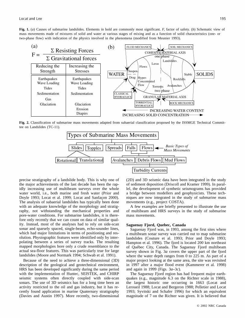
A compilation of the possible elements that can initiate asubmarine landslide is presented in Fig. 1a. Some causes areunique to the marine environment, i.e., role of gas charging,diapirism, and wave action. Materials involved in submarinemass movements are as diverse as those on land, i.e., rock,soil, mud, and mixtures of all three. Because of the potentialextent of submarine mass movements, we have to considerall the components of the phenomena, i.e., initiation, transi-tion into debris flow (Norem et al. 1990), subsequent forma-tion of a turbidity current (Normark and Piper 1991), andmovement on the sea floor until final deposition. Here wemust distinguish the cases where turbidity currents can bedirectly generated by hyperpicnal flows originating at themouths of major rivers entering the ocean, as often seen infjords (Syvitski et al. 1987; Mulder and Syvitski 1995), fromthose originating from mass movements or debris flows. Toillustrate the continuity of the mass movement phenomena,we borrowed a diagram proposed by Meunier (1993) (Fig. 1b).This diagram has two axes, namely granular and cohesive,and takes into account the relative proportion of solids andwater. Therefore, depending on the type of mixture (one ortwo phases), the behaviour of the mixture will be best ana-lysed by soil–rock mechanics principles, fluid mechanics, ortorrential hydraulics. This means, for example, that for mud-flows, where the rate of movement is fast enough that thereis no time for excess pore-water dissipation, the mechanicsof the movement cannot be adequately explained by soil me-chanics but rather by fluid mechanics principles. For a com-prehensive review of debris-flow mechanics, the reader isreferred to the work of Iverson (1997).
The various types of mass movements that can be in-volved are summarized in Fig. 2, which is an adjustment ofthe same classification proposed for subaerial mass move-ments by the International Society for Soil Mechanics andGeotechnical Engineering (ISSMGE) Technical Committeeon Landslides (TC-11). Here, the only addition is that of tur-bidity currents. All the types indicated here are mutually ex-clusive, for instance, a slide cannot be a fall. Some types ofmass movements, like slides, will be recognisable by the dis-rupted step-like morphology indicative of little displacementof the failed mass. In a slide, the displaced material moveson a relatively thin zone of intense strain. At the extreme
case as for flows, the slide area will be emptied and thefailed mass may be deposited many hundreds of kilometresaway from its source (Schwab et al. 1996). In a fall, the dis-placed material descends mainly through water, falling,bouncing, and rolling. Of course, one type of mass move-ment can lead to another, e.g., a slide can transform into aflow. One could introduce subdivisions (e.g., Prior 1984;Mulder and Cochonat 1996; Norem et al. 1990), but theterms presented in Fig. 2 can cover most of the observedphenomena.
A first observation based on the above presentation is thatif we wish to carry out a risk assessment related to subma-rine landslides, we must take into account the various com-ponents of the phenomenon, i.e., from failure initiation tothe final deposition, which will require scientific consider-ation covering all the physics involved. As a contribution tothis issue, Leroueil et al. (1996) proposed a general frame-work called geotechnical characterization of mass movementswhich incorporates three basic elements: (i) the materials,(ii) the slope movements, and (iii) the movement stages.These stages are as follows: (i) the prefailure stage, whenthe sediment or rock mass is essentially in a state of equilib-rium and intact; (ii) the failure stage, in which the onset offailure is characterized by the formation of continuous shearbands or surface through the entire mass originating fromvarious causes; (iii) the post-failure stage, which involvesthe behaviour of the sliding mass until it essentially stops;and (iv) the reactivation stage, which relates to movementson preexisting failure planes or failed masses.
The driving mechanisms of submarine mass movementswill vary according to the causes but also according to theenvironment in which the mass movements will occur. Forexample, the Grand Banks slide was triggered by an earth-quake, but the open ocean margin provided ideal conditionsfor the development of a large turbidity current. In the caseof the debris flows on the Mississippi Fan, their large traveldistances can only be explained by the presence of awell-developed channel system (Schwab et al. 1996; Locatet al. 1996). Therefore, considering the various stages ofmass movement is an important step in bringing together thevarious driving mechanisms. In many cases, we have ob-served that at the failure stage, soil or rock mechanics prin-ciples are needed to explain or predict the stability. However,for the post-failure stage, very often the approach must relyon fluid mechanics principles.
Geomorphology and architecture
The initial knowledge of potential problems, in a givenarea, is often evidenced by geomorphological features whichmay suggest that the sea floor or slope has been disrupted ina catastrophic manner. The geomorphological setting of alandslide constitutes its final stage unless it is reactivatedand, in itself, is a major revealing factor of the potentialproblem at a local and regional scale. With the developmentof multibeam techniques (Mitchell 1991; Li and Clark 1991;Prior and Doyle 1993; Hughes Clarke et al. 1996), differen-tial global positioning systems (DGPS), and high-resolutionseismics (HRS) (Davies and Austin 1997), we can now pro-duce precise bathymetric maps of near air-photograph qual-ity (Bellaiche 1993; Urgeles et al. 1997) and define the
© 2002 NRC Canada
194 Can. Geotech. J. Vol. 39, 2002
I:\cgj\Cgj39\Cgj-01\T01-089.vpFriday, February 15, 2002 1:23:01 PM
Color profile: DisabledComposite Default screen
precise stratigraphy of a landslide body. This is why one ofthe major achievements of the last decade has been the rap-idly increasing use of multibeam surveys over the wholewater world, i.e., both marine and fresh water (Prior andDoyle 1993; Locat et al. 1999; Locat and Sanfaçon 2000).The analysis of subaerial landslides has typically been donewith an adequate knowledge of the morphology and stratig-raphy, not withstanding the mechanical properties andpore-water conditions. For submarine landslides, it is there-fore only recently that we can count on data of similar qual-ity. Instead, most of the analyses had to rely on side-scansonar and sparsely spaced, single-beam, echo-sounder lines,which had major limitations in terms of positioning and res-olution. Physiographic features were identified only by inter-polating between a series of survey tracks. The resultingmapped morphologies bore only a crude resemblance to theactual sea-floor features. This was particularly true for largelandslides (Moore and Normark 1994; Schwab et al. 1991).
Because of the need to achieve a three-dimensional (3D)description of the geological and geotechnical environment,HRS has been developed significantly during the same periodwith the implementation of Huntec, SEISTEK, and CHIRPseismic systems often directly coupled with side-scansonars. The use of 3D seismics has for a long time been anactivity restricted to the oil and gas industry, but it has re-cently found application in marine Quaternary stratigraphy(Davies and Austin 1997). More recently, two-dimensional
(2D) and 3D seismic data have been integrated in the studyof sediment deposition (Driscoll and Kramer 1999). In paral-lel, the development of synthetic seismograms has provideda bridge between modellers and geophysicists. These tech-niques are now integrated in the study of submarine massmovements (e.g., project COSTA).
A few examples are briefly presented to illustrate the useof multibeam and HRS surveys in the study of submarinemass movements.
Saguenay Fjord, Quebec, CanadaSaguenay Fjord was, in 1993, among the first sites where
a multibeam sonar survey was carried out to map submarinelandslides (Couture et al. 1993; Prior and Doyle 1993;Hampton et al. 1996). The fjord is located 200 km northeastof Québec City, Canada. The Saguenay Fjord multibeamsurvey shown in Fig. 3a covers the upper part of the fjordwhere the water depth ranges from 0 to 225 m. As part of amajor project looking at the same area, the site was revisitedin 1997 after a major flood event (Kammerer et al. 1998)and again in 1999 (Figs. 3a–3c).
The Saguenay Fjord region has had frequent major earth-quakes (e.g., magnitude 6.3 on the Richter scale in 1988),the largest historic one occurring in 1663 (Locat andLeroueil 1988; Locat and Bergeron 1988; Pelletier and Locat1993; Syvitski and Schafer 1996) for which an equivalentmagnitude of 7 on the Richter was given. It is believed that
© 2002 NRC Canada
Locat and Lee 195
Fig. 1. (a) Causes of submarine landslides. Elements in bold are commonly most significant. F, factor of safety. (b) Schematic view ofmass movements made of mixtures of solid and water at various stages of mixing and as a function of solid characteristics (one- ortwo-phase flow) with indication of the physics involved in the phenomena (modified from Meunier 1993).
Fig. 2. Classification of submarine mass movements adapted from subaerial classification proposed by the ISSMGE Technical Commit-tee on Landslides (TC-11).
I:\cgj\Cgj39\Cgj-01\T01-089.vpFriday, February 15, 2002 1:23:01 PM
Color profile: DisabledComposite Default screen
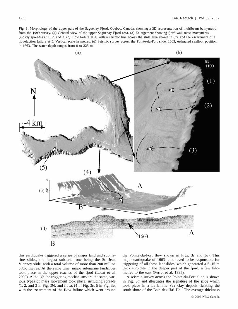
this earthquake triggered a series of major land and subma-rine slides, the largest subaerial one being the St. JeanVianney slide, with a total volume of more than 200 millioncubic metres. At the same time, major submarine landslidestook place in the upper reaches of the fjord (Locat et al.2000). Although the triggering mechanisms are the same, var-ious types of mass movement took place, including spreads(1, 2, and 3 in Fig. 3b), and flows (4 in Fig. 3c, 5 in Fig. 3a,with the escarpment of the flow failure which went around
the Pointe-du-Fort flow shown in Figs. 3c and 3d). Thismajor earthquake of 1663 is believed to be responsible fortriggering of all these landslides, which generated a 5–15 mthick turbidite in the deeper part of the fjord, a few kilo-metres to the east (Perret et al. 1995).
A seismic survey across the Pointe-du-Fort slide is shownin Fig. 3d and illustrates the signature of the slide whichtook place in a Laflamme Sea clay deposit flanking thesouth shore of the Baie des Ha! Ha!. The average thickness
© 2002 NRC Canada
196 Can. Geotech. J. Vol. 39, 2002
Fig. 3. Morphology of the upper part of the Saguenay Fjord, Quebec, Canada, showing a 3D representation of multibeam bathymetryfrom the 1999 survey. (a) General view of the upper Saguenay Fjord area. (b) Enlargement showing fjord wall mass movements(mostly spreads) at 1, 2, and 3. (c) Flow failure at 4, with a seismic line across the slide area shown in (d), and the escarpment of aliquefaction failure at 5. Vertical scale in metres. (d) Seismic survey across the Pointe-du-Fort slide. 1663, estimated seafloor positionin 1663. The water depth ranges from 0 to 225 m.
I:\cgj\Cgj39\Cgj-01\T01-089.vpFriday, February 15, 2002 1:23:11 PM
Color profile: DisabledComposite Default screen
of the flow failure deposit is about 15 m and the totalrun-out distance is about 800 m. A transparent layer can beseen on both sides of the slide and represents the mudflowdeposit generated by the large liquefaction failure whichoriginated in the centre of the Baie des Ha! Ha!. ThePointe-du-Fort slide (4 in Fig. 3c) partly dammed this mudflowdeposit, which is thicker on the upstream side of the slide.
Palos Verdes slide, California, U.S.A.The Palos Verdes slide (Fig. 4) is located along the San
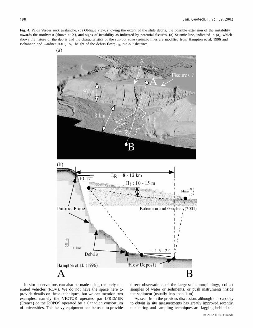
Pedro escarpment just offshore of Los Angeles. The seafloor lying at the base of the escarpment is the San PedroBasin, which had long been recognised based on seismic re-flection logs (Gorsline et al. 1984). The slope itself is formedof sedimentary rocks dipping between 10 and 15°. The slopeis eroded by a series of gullies 2–4 km apart. The base of theslope would more or less coincide with the trace of the SanPedro fault (Bohannon and Gardner 2001). The slide tookplace along a steep escarpment, mobilized into a debris ava-lanche, and travelled a distance of about 8 km out onto theadjacent basin floor (Fig. 4b). The head scarp is about 600 mhigh and the slope varies between 10 and 20°. The debriswas dispersed over a wide area shown in Fig. 4a. From seis-mic records the thickness of the debris deposit varies fromabout 20 m in the lower part of the slope to less than 1 mabout 8 km away from the base of the slope, with an averagethickness of 5–10 m (Fig. 4b). The coupling of both the seis-mic survey and the multibeam survey does provide a com-prehensive picture of the nature of this slide and its extent.An analysis of the run-out distance of the debris indicatesthat the initial sliding mass was large enough and had suffi-cient potential energy to trigger a tsunami and reach the ob-served run-out distance (Locat et al. 2001). A detailedobservation of the escarpment and the shelf edge reveals thatthe erosion process is continuing and may be in a north-westward direction (see X in Fig. 4a).
Canary Islands rock avalanches, SpainThe Canary Islands rock avalanches have been initiated on
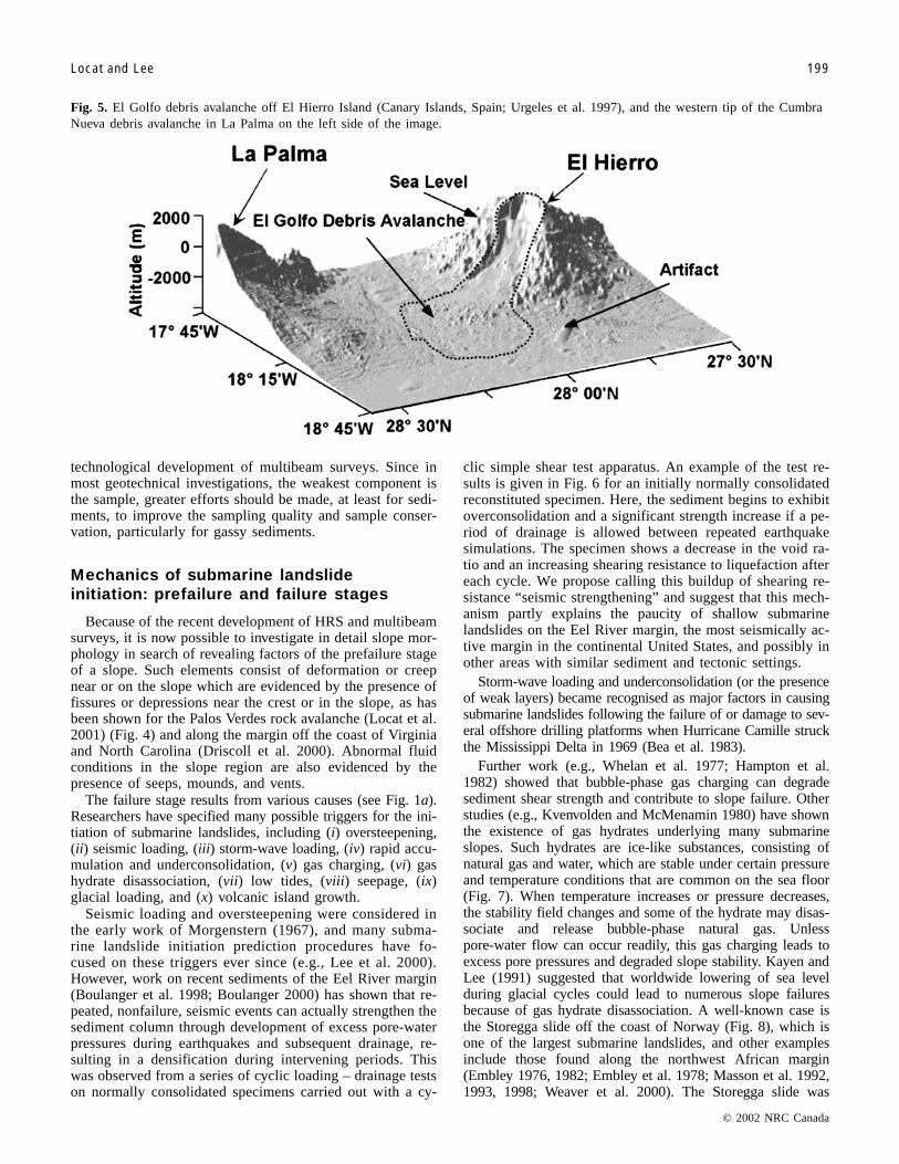
the non-buttressed flanks of the island, which is bounded bythe rift systems where most volcanic eruptions take place(Fig. 5). The avalanches retrogressed almost to the top of theisland (1500 m elevation) in El Hierro (Fig. 5), 2400 m inLa Palma, and 3700 m in Tenerife, which has the third high-est oceanic volcano on Earth after Mauna Loa and MonaKea in Hawaii (Moore et al. 1992, 1995). These avalanchestravelled distances of between 50 and 100 km down to oceandepths of up to 4000 m and involved volumes of up to sev-eral hundred cubic kilometres (Urgeles et al. 1997, 1999;Watts and Masson 1995, 1998). The El Hierro submarinerock avalanche shown in Fig. 5 covers an area of 2600 km2
for a volume of about 150 km3 (Urgeles et al. 1997). Thistype of mass movement is very similar to those reported byMoore and Normark (1994) for the Hawaiian Islands. Majorrock avalanches are now reported around many volcanic is-lands (e.g., Elsworth and Voight 1995; Voight and Elsworth1997; F. Chiocci, personal communication, for StromboliIsland).
The aforementioned selection of submarine mass move-ments has illustrated how the new developments in bothmultibeam and seismic surveys have enabled us to achieve a
fine description of these phenomena. For the future, thechallenge lies in integrating this morphological and seismicinformation with geotechnical profiles to provide a 3D viewof the rock or soil properties involved in mass movements oralong a slope. Some direction and examples are provided byHart (1999), who has coupled 3D seismics with rock proper-ties to create a 3D distribution of rock properties.
Geotechnical investigations of submarinelandslides
Coring and samplingAlthough seismic and multibeam surveys can be carried
out in a cost-effective manner, sampling and in situ testingare not as easy and are often much more costly for the samelevel of quality. Except for cases involving offshore resourcessuch as oil and gas, in most situations sampling of sedimentsis done by means of gravity methods such as the following:Calypso (up to 60 m, mounted aboard the Marion DufresnesII, Institute français de recherche pour l’exploitation de lamer (IFREMER)); Long Coring Facility (up to 30 m, Geo-science Atlantic, Canada) which is similar to the Jumbo Pis-ton Corer (JPC) of the University of Rhode Island (Silva etal. 1999); Lehigh (up to 3 m); Kastin corer (up to 3 m); andbox corer (0.6 m) and surface sampler (Shipek, VanVeen).The best coring method for sediments, in terms of geo-technical sample quality, is the box corer, but it has a verylimited penetration. All other methods have their intrinsicdifficulties mainly related to the partial remoulding of thesoil during the penetration in the sediment and the presenceof gas. For the case of gas hydrates, gas hydrate autoclavecoring equipment (HYACE) is being developed by a Euro-pean consortium composed of the Technical University ofBerlin, the Ocean Drilling Program (ODP), and GEOTEK(U.K.). The proposed technology will maintain the sampleunder pressure while various nondestructive geophysicaltesting methods are used. For rock sampling or very stiffsediments, techniques developed by the ODP are good butvery expensive and usually out of reach for most studies. Arecent drilling tool, called the portable remotely operateddrill (PROD, Benthic GeoTech, Australia), has been de-signed to drill into about 10–100 m of sediments or rock inwater depths up to 2500 m. Its only limitation, from a geo-technical viewpoint, is the size of the core barrel (6 cm).
In situ testing and direct observationsCore quality is still a major issue in geotechnical investi-
gations of submarine slides, particularly at sites where gascontent is high enough to produce significant disturbance ofthe sample, often once it is on the ship’s deck. In addition tosamples, information required on pore pressures can bemade via in situ techniques that have been developed forgeneral purposes but can be used in submarine landslide in-vestigations. The Lancelot and Excalibur probes were de-signed as a piezocone, which can also collect gas samples(Christian et al. 1993, 1994). A similar probe, called PUPPI(pop up pore pressure instrument) has been developed tomeasure pore pressure in sediments (Schultheiss 1990).IFREMER has also developed a falling cone penetrometer(PENFELD). All of these are gravity methods and theirmaximum penetration depth is less than 10 m.
© 2002 NRC Canada
Locat and Lee 197
I:\cgj\Cgj39\Cgj-01\T01-089.vpFriday, February 15, 2002 1:23:11 PM
Color profile: DisabledComposite Default screen
In situ observations can also be made using remotely op-erated vehicles (ROV). We do not have the space here toprovide details on these techniques, but we can mention twoexamples, namely the VICTOR operated par IFREMER(France) or the ROPOS operated by a Canadian consortiumof universities. This heavy equipment can be used to provide
direct observations of the large-scale morphology, collectsamples of water or sediments, or push instruments insidethe sediment (usually less than 1 m).
As seen from the previous discussion, although our capacityto obtain in situ measurements has greatly improved recently,our coring and sampling techniques are lagging behind the
© 2002 NRC Canada
198 Can. Geotech. J. Vol. 39, 2002
Fig. 4. Palos Verdes rock avalanche. (a) Oblique view, showing the extent of the slide debris, the possible extension of the instabilitytowards the northwest (shown at X), and signs of instability as indicated by potential fissures. (b) Seismic line, indicated in (a), whichshows the nature of the debris and the characteristics of the run-out zone (seismic lines are modified from Hampton et al. 1996 andBohannon and Gardner 2001). Hf , height of the debris flow; LR, run-out distance.
I:\cgj\Cgj39\Cgj-01\T01-089.vpFriday, February 15, 2002 1:23:20 PM
Color profile: DisabledComposite Default screen
technological development of multibeam surveys. Since inmost geotechnical investigations, the weakest component isthe sample, greater efforts should be made, at least for sedi-ments, to improve the sampling quality and sample conser-vation, particularly for gassy sediments.
Mechanics of submarine landslideinitiation: prefailure and failure stages
Because of the recent development of HRS and multibeamsurveys, it is now possible to investigate in detail slope mor-phology in search of revealing factors of the prefailure stageof a slope. Such elements consist of deformation or creepnear or on the slope which are evidenced by the presence offissures or depressions near the crest or in the slope, as hasbeen shown for the Palos Verdes rock avalanche (Locat et al.2001) (Fig. 4) and along the margin off the coast of Virginiaand North Carolina (Driscoll et al. 2000). Abnormal fluidconditions in the slope region are also evidenced by thepresence of seeps, mounds, and vents.
The failure stage results from various causes (see Fig. 1a).Researchers have specified many possible triggers for the ini-tiation of submarine landslides, including (i) oversteepening,(ii) seismic loading, (iii) storm-wave loading, (iv) rapid accu-mulation and underconsolidation, (v) gas charging, (vi) gashydrate disassociation, (vii) low tides, (viii) seepage, (ix)glacial loading, and (x) volcanic island growth.
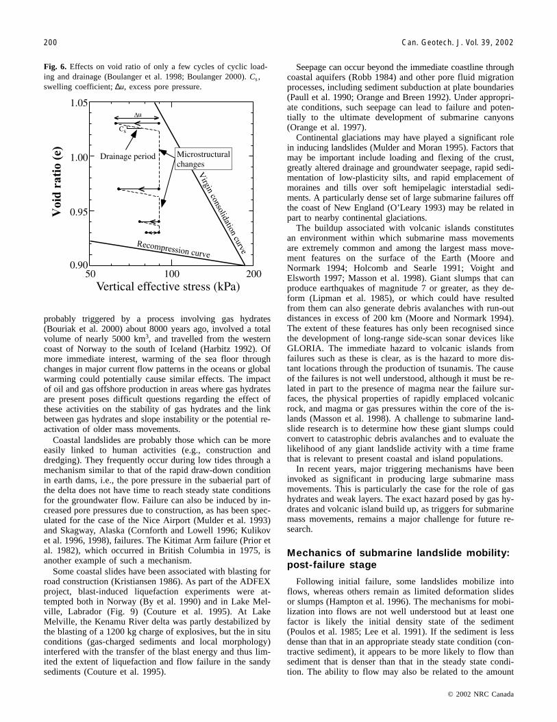
Seismic loading and oversteepening were considered inthe early work of Morgenstern (1967), and many subma-rine landslide initiation prediction procedures have fo-cused on these triggers ever since (e.g., Lee et al. 2000).However, work on recent sediments of the Eel River margin(Boulanger et al. 1998; Boulanger 2000) has shown that re-peated, nonfailure, seismic events can actually strengthen thesediment column through development of excess pore-waterpressures during earthquakes and subsequent drainage, re-sulting in a densification during intervening periods. Thiswas observed from a series of cyclic loading – drainage testson normally consolidated specimens carried out with a cy-
clic simple shear test apparatus. An example of the test re-sults is given in Fig. 6 for an initially normally consolidatedreconstituted specimen. Here, the sediment begins to exhibitoverconsolidation and a significant strength increase if a pe-riod of drainage is allowed between repeated earthquakesimulations. The specimen shows a decrease in the void ra-tio and an increasing shearing resistance to liquefaction aftereach cycle. We propose calling this buildup of shearing re-sistance “seismic strengthening” and suggest that this mech-anism partly explains the paucity of shallow submarinelandslides on the Eel River margin, the most seismically ac-tive margin in the continental United States, and possibly inother areas with similar sediment and tectonic settings.
Storm-wave loading and underconsolidation (or the presenceof weak layers) became recognised as major factors in causingsubmarine landslides following the failure of or damage to sev-eral offshore drilling platforms when Hurricane Camille struckthe Mississippi Delta in 1969 (Bea et al. 1983).
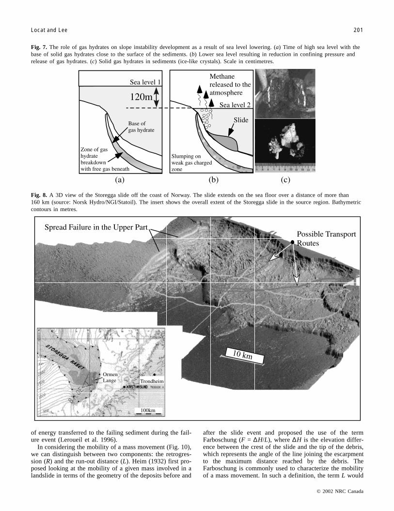
Further work (e.g., Whelan et al. 1977; Hampton et al.1982) showed that bubble-phase gas charging can degradesediment shear strength and contribute to slope failure. Otherstudies (e.g., Kvenvolden and McMenamin 1980) have shownthe existence of gas hydrates underlying many submarineslopes. Such hydrates are ice-like substances, consisting ofnatural gas and water, which are stable under certain pressureand temperature conditions that are common on the sea floor(Fig. 7). When temperature increases or pressure decreases,the stability field changes and some of the hydrate may disas-sociate and release bubble-phase natural gas. Unlesspore-water flow can occur readily, this gas charging leads toexcess pore pressures and degraded slope stability. Kayen andLee (1991) suggested that worldwide lowering of sea levelduring glacial cycles could lead to numerous slope failuresbecause of gas hydrate disassociation. A well-known case isthe Storegga slide off the coast of Norway (Fig. 8), which isone of the largest submarine landslides, and other examplesinclude those found along the northwest African margin(Embley 1976, 1982; Embley et al. 1978; Masson et al. 1992,1993, 1998; Weaver et al. 2000). The Storegga slide was
© 2002 NRC Canada
Locat and Lee 199
Fig. 5. El Golfo debris avalanche off El Hierro Island (Canary Islands, Spain; Urgeles et al. 1997), and the western tip of the CumbraNueva debris avalanche in La Palma on the left side of the image.
I:\cgj\Cgj39\Cgj-01\T01-089.vpFriday, February 15, 2002 1:23:26 PM
Color profile: DisabledComposite Default screen
probably triggered by a process involving gas hydrates(Bouriak et al. 2000) about 8000 years ago, involved a totalvolume of nearly 5000 km3, and travelled from the westerncoast of Norway to the south of Iceland (Harbitz 1992). Ofmore immediate interest, warming of the sea floor throughchanges in major current flow patterns in the oceans or globalwarming could potentially cause similar effects. The impactof oil and gas offshore production in areas where gas hydratesare present poses difficult questions regarding the effect ofthese activities on the stability of gas hydrates and the linkbetween gas hydrates and slope instability or the potential re-activation of older mass movements.
Coastal landslides are probably those which can be moreeasily linked to human activities (e.g., construction anddredging). They frequently occur during low tides through amechanism similar to that of the rapid draw-down conditionin earth dams, i.e., the pore pressure in the subaerial part ofthe delta does not have time to reach steady state conditionsfor the groundwater flow. Failure can also be induced by in-creased pore pressures due to construction, as has been spec-ulated for the case of the Nice Airport (Mulder et al. 1993)and Skagway, Alaska (Cornforth and Lowell 1996; Kulikovet al. 1996, 1998), failures. The Kitimat Arm failure (Prior etal. 1982), which occurred in British Columbia in 1975, isanother example of such a mechanism.
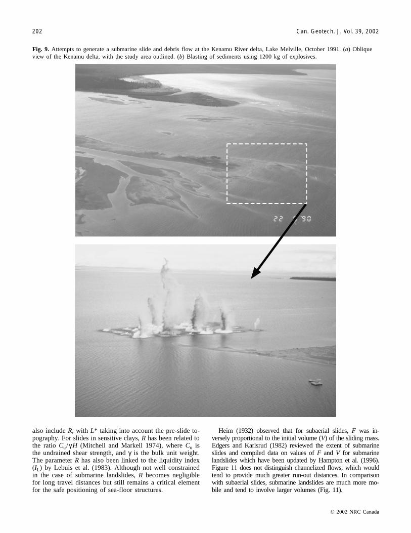
Some coastal slides have been associated with blasting forroad construction (Kristiansen 1986). As part of the ADFEXproject, blast-induced liquefaction experiments were at-tempted both in Norway (By et al. 1990) and in Lake Mel-ville, Labrador (Fig. 9) (Couture et al. 1995). At LakeMelville, the Kenamu River delta was partly destabilized bythe blasting of a 1200 kg charge of explosives, but the in situconditions (gas-charged sediments and local morphology)interfered with the transfer of the blast energy and thus lim-ited the extent of liquefaction and flow failure in the sandysediments (Couture et al. 1995).
Seepage can occur beyond the immediate coastline throughcoastal aquifers (Robb 1984) and other pore fluid migrationprocesses, including sediment subduction at plate boundaries(Paull et al. 1990; Orange and Breen 1992). Under appropri-ate conditions, such seepage can lead to failure and poten-tially to the ultimate development of submarine canyons(Orange et al. 1997).
Continental glaciations may have played a significant rolein inducing landslides (Mulder and Moran 1995). Factors thatmay be important include loading and flexing of the crust,greatly altered drainage and groundwater seepage, rapid sedi-mentation of low-plasticity silts, and rapid emplacement ofmoraines and tills over soft hemipelagic interstadial sedi-ments. A particularly dense set of large submarine failures offthe coast of New England (O’Leary 1993) may be related inpart to nearby continental glaciations.
The buildup associated with volcanic islands constitutesan environment within which submarine mass movementsare extremely common and among the largest mass move-ment features on the surface of the Earth (Moore andNormark 1994; Holcomb and Searle 1991; Voight andElsworth 1997; Masson et al. 1998). Giant slumps that canproduce earthquakes of magnitude 7 or greater, as they de-form (Lipman et al. 1985), or which could have resultedfrom them can also generate debris avalanches with run-outdistances in excess of 200 km (Moore and Normark 1994).The extent of these features has only been recognised sincethe development of long-range side-scan sonar devices likeGLORIA. The immediate hazard to volcanic islands fromfailures such as these is clear, as is the hazard to more dis-tant locations through the production of tsunamis. The causeof the failures is not well understood, although it must be re-lated in part to the presence of magma near the failure sur-faces, the physical properties of rapidly emplaced volcanicrock, and magma or gas pressures within the core of the is-lands (Masson et al. 1998). A challenge to submarine land-slide research is to determine how these giant slumps couldconvert to catastrophic debris avalanches and to evaluate thelikelihood of any giant landslide activity with a time framethat is relevant to present coastal and island populations.
In recent years, major triggering mechanisms have beeninvoked as significant in producing large submarine massmovements. This is particularly the case for the role of gashydrates and weak layers. The exact hazard posed by gas hy-drates and volcanic island build up, as triggers for submarinemass movements, remains a major challenge for future re-search.
Mechanics of submarine landslide mobility:post-failure stage
Following initial failure, some landslides mobilize intoflows, whereas others remain as limited deformation slidesor slumps (Hampton et al. 1996). The mechanisms for mobi-lization into flows are not well understood but at least onefactor is likely the initial density state of the sediment(Poulos et al. 1985; Lee et al. 1991). If the sediment is lessdense than that in an appropriate steady state condition (con-tractive sediment), it appears to be more likely to flow thansediment that is denser than that in the steady state condi-tion. The ability to flow may also be related to the amount
© 2002 NRC Canada
200 Can. Geotech. J. Vol. 39, 2002
Fig. 6. Effects on void ratio of only a few cycles of cyclic load-ing and drainage (Boulanger et al. 1998; Boulanger 2000). Cs ,swelling coefficient; ∆u, excess pore pressure.
I:\cgj\Cgj39\Cgj-01\T01-089.vpFriday, February 15, 2002 1:23:26 PM
Color profile: DisabledComposite Default screen
of energy transferred to the failing sediment during the fail-ure event (Leroueil et al. 1996).
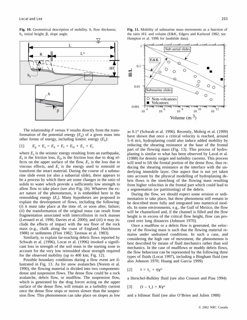
In considering the mobility of a mass movement (Fig. 10),we can distinguish between two components: the retrogres-sion (R) and the run-out distance (L). Heim (1932) first pro-posed looking at the mobility of a given mass involved in alandslide in terms of the geometry of the deposits before and
after the slide event and proposed the use of the termFarboschung (F = ∆H/L), where ∆H is the elevation differ-ence between the crest of the slide and the tip of the debris,which represents the angle of the line joining the escarpmentto the maximum distance reached by the debris. TheFarboschung is commonly used to characterize the mobilityof a mass movement. In such a definition, the term L would
© 2002 NRC Canada
Locat and Lee 201
Fig. 7. The role of gas hydrates on slope instability development as a result of sea level lowering. (a) Time of high sea level with thebase of solid gas hydrates close to the surface of the sediments. (b) Lower sea level resulting in reduction in confining pressure andrelease of gas hydrates. (c) Solid gas hydrates in sediments (ice-like crystals). Scale in centimetres.
Fig. 8. A 3D view of the Storegga slide off the coast of Norway. The slide extends on the sea floor over a distance of more than160 km (source: Norsk Hydro/NGI/Statoil). The insert shows the overall extent of the Storegga slide in the source region. Bathymetriccontours in metres.
I:\cgj\Cgj39\Cgj-01\T01-089.vpFriday, February 15, 2002 1:23:31 PM
Color profile: DisabledComposite Default screen
© 2002 NRC Canada
202 Can. Geotech. J. Vol. 39, 2002
also include R, with L* taking into account the pre-slide to-pography. For slides in sensitive clays, R has been related tothe ratio Cu/γH (Mitchell and Markell 1974), where Cu isthe undrained shear strength, and γ is the bulk unit weight.The parameter R has also been linked to the liquidity index(IL) by Lebuis et al. (1983). Although not well constrainedin the case of submarine landslides, R becomes negligiblefor long travel distances but still remains a critical elementfor the safe positioning of sea-floor structures.
Heim (1932) observed that for subaerial slides, F was in-versely proportional to the initial volume (V) of the sliding mass.Edgers and Karlsrud (1982) reviewed the extent of submarineslides and compiled data on values of F and V for submarinelandslides which have been updated by Hampton et al. (1996).Figure 11 does not distinguish channelized flows, which wouldtend to provide much greater run-out distances. In comparisonwith subaerial slides, submarine landslides are much more mo-bile and tend to involve larger volumes (Fig. 11).
Fig. 9. Attempts to generate a submarine slide and debris flow at the Kenamu River delta, Lake Melville, October 1991. (a) Obliqueview of the Kenamu delta, with the study area outlined. (b) Blasting of sediments using 1200 kg of explosives.
I:\cgj\Cgj39\Cgj-01\T01-089.vpFriday, February 15, 2002 1:23:41 PM
Color profile: DisabledComposite Default screen
© 2002 NRC Canada
Locat and Lee 203
The relationship F versus V results directly from the trans-formation of the potential energy (Ep) of a given mass intoother forms of energy, including kinetic energy (Ek):
[1] Ep + Es = Ek + Ef + ED + Ev + Er
where Es is the seismic energy resulting from an earthquake,Ef is the friction loss, ED is the friction loss due to drag ef-fects on the upper surface of the flow, Ev is the loss due toviscous effects, and Er is the energy used to remould ortransform the intact material. During the course of a subma-rine slide event (or also a subaerial slide), there appears tobe a process by which there are some changes in the ratio ofsolids to water which provide a sufficiently low strength toallow flow to take place (see also Fig. 1b). Whatever the ex-act nature of the phenomenon, it is embedded here in theremoulding energy (Er). Many hypotheses are proposed toexplain the development of flows, including the following:(i) it must take place at the time of, or soon after, failure;(ii) the transformation of the original mass can result fromfragmentation associated with intercollision in rock masses(Leroueil et al. 1996; Davies et al. 2000); and (iii) it may in-clude the effects of impact with the sea floor of the rockmass (e.g., chalk along the coast of England; Hutchinson1988) or sediments (Flon 1982; Tavenas et al. 1983).
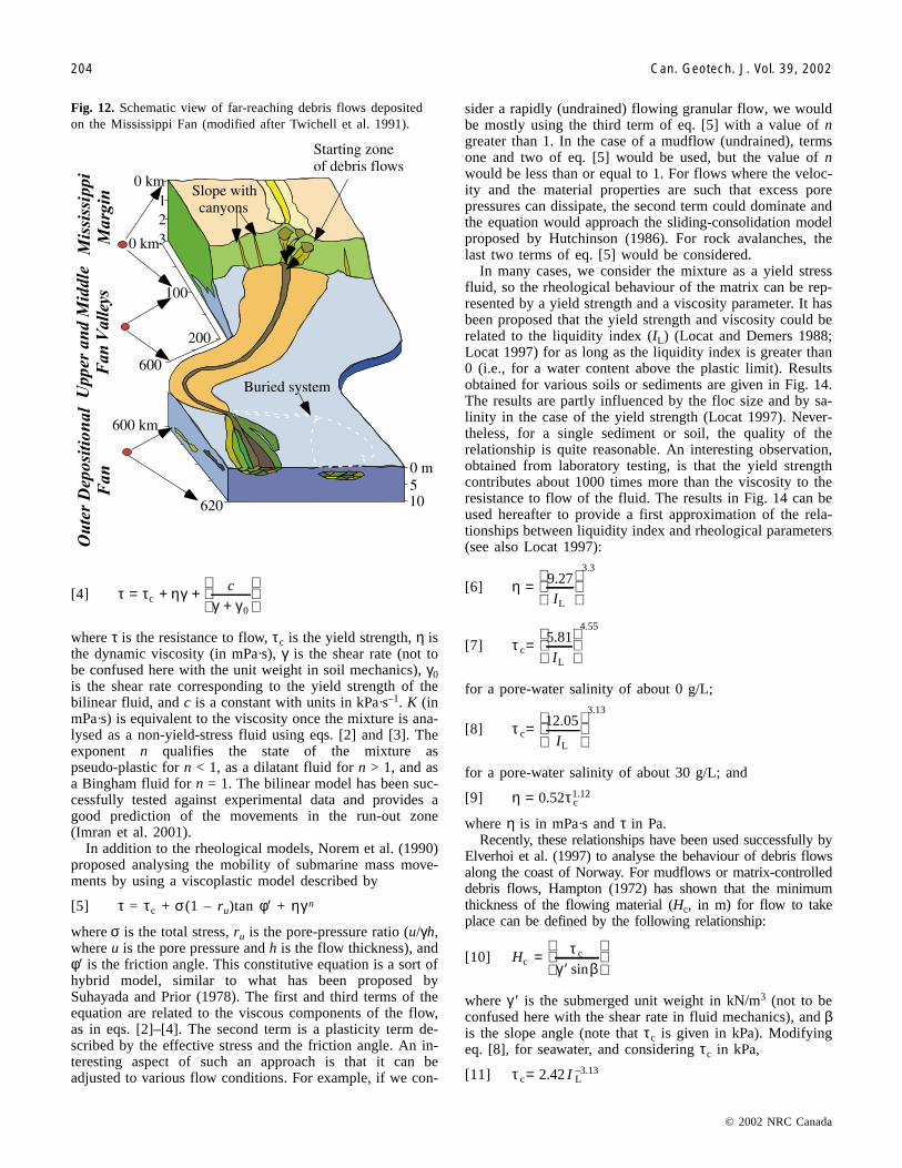
Similarly, to explain far-reaching debris flows reported bySchwab et al. (1996), Locat et al. (1996) invoked a signifi-cant loss in strength of the soil mass in the starting zone toaccount for the very low remoulded shear strength requiredfor the observed mobility (up to 400 km; Fig. 12).
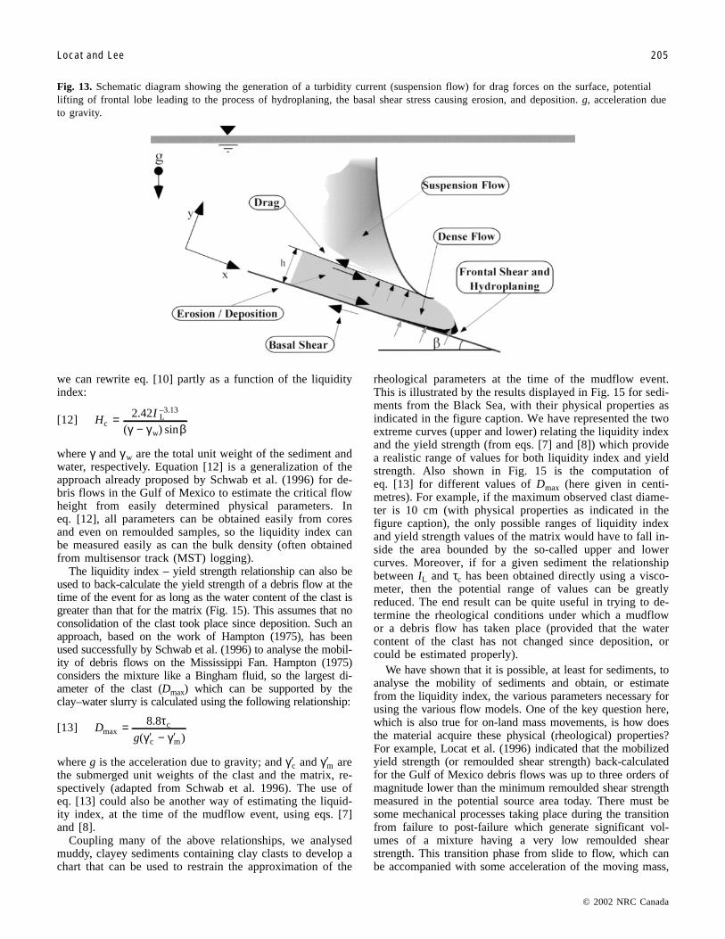
Possible boundary conditions during a flow event are il-lustrated in Fig. 13. As for snow avalanches (Norem et al.1990), the flowing material is divided into two components:dense and suspension flows. The dense flow could be a rockavalanche, debris flow, or mudflow. The suspension flow,which is generated by the drag forces acting on the uppersurface of the dense flow, will remain as a turbidity currentonce the dense flow stops or moves slower than the suspen-sion flow. This phenomenon can take place on slopes as low
as 0.1° (Schwab et al. 1996). Recently, Mohrig et al. (1999)have shown that once a critical velocity is reached, around5–6 m/s, hydroplaning could also induce added mobility byreducing the shearing resistance at the base of the frontalpart of the flowing mass (Fig. 13). This process of hydro-planing is similar to what has been observed by Laval et al.(1988) for density surges and turbidity currents. This processwill tend to lift the frontal portion of the dense flow, thus re-ducing the shearing resistance at the interface with the un-derlying immobile layer. One aspect that is not yet takeninto account by the physical modelling of hydroplaning de-bris flows is the stretching of the flowing mass resultingfrom higher velocities in the frontal part which could lead toa segmentation (or partitioning) of the debris.
During the flow, we should expect some erosion or sedi-mentation to take place, but these phenomena still remain tobe described more fully and integrated into numerical mod-els. In some environments, e.g., the Gulf of Mexico, the flowwill be channelized and, if the channel is filled and the flowheight is in excess of the critical flow height, flow can pro-ceed over long distances (Johnson 1970).
Once a mudflow or a debris flow is generated, the veloc-ity of the flowing mass is such that the flowing material re-mains under undrained conditions. In such a case, andconsidering the high rate of movement, the phenomenon isbest described by means of fluid mechanics rather than soilmechanics. In the case of mudflows or muddy debris flows,the flow behaviour can be represented by the following threetypes of fluids (Locat 1997), including a Bingham fluid (seealso Johnson 1970; Huang and Garcia 1999)
[2] τ = τc + ηγn
a Herschel-Bulkley fluid (see also Coussot and Piau 1994)
[3] (τ – τc) = Kγn
and a bilinear fluid (see also O’Brien and Julien 1988)
Fig. 10. Geometrical description of mobility. h, flow thickness;hi, initial height; β, slope angle.
Fig. 11. Mobility of submarine mass movements as a function ofthe ratio H/L and volume (E&K, Edgers and Karlsrud 1982; seeHampton et al. 1996 for landslide data).
I:\cgj\Cgj39\Cgj-01\T01-089.vpFriday, February 15, 2002 1:23:42 PM
Color profile: DisabledComposite Default screen
[4] τ τ ηγγ γ
= + ++
c
c
0
where τ is the resistance to flow, τc is the yield strength, η isthe dynamic viscosity (in mPa·s), γ is the shear rate (not tobe confused here with the unit weight in soil mechanics), γ0is the shear rate corresponding to the yield strength of thebilinear fluid, and c is a constant with units in kPa·s–1. K (inmPa·s) is equivalent to the viscosity once the mixture is ana-lysed as a non-yield-stress fluid using eqs. [2] and [3]. Theexponent n qualifies the state of the mixture aspseudo-plastic for n < 1, as a dilatant fluid for n > 1, and asa Bingham fluid for n = 1. The bilinear model has been suc-cessfully tested against experimental data and provides agood prediction of the movements in the run-out zone(Imran et al. 2001).
In addition to the rheological models, Norem et al. (1990)proposed analysing the mobility of submarine mass move-ments by using a viscoplastic model described by
[5] τ = τc + σ(1 – ru)tan φ′ + ηγn
where σ is the total stress, ru is the pore-pressure ratio (u/γh,where u is the pore pressure and h is the flow thickness), andφ′ is the friction angle. This constitutive equation is a sort ofhybrid model, similar to what has been proposed bySuhayada and Prior (1978). The first and third terms of theequation are related to the viscous components of the flow,as in eqs. [2]–[4]. The second term is a plasticity term de-scribed by the effective stress and the friction angle. An in-teresting aspect of such an approach is that it can beadjusted to various flow conditions. For example, if we con-
sider a rapidly (undrained) flowing granular flow, we wouldbe mostly using the third term of eq. [5] with a value of ngreater than 1. In the case of a mudflow (undrained), termsone and two of eq. [5] would be used, but the value of nwould be less than or equal to 1. For flows where the veloc-ity and the material properties are such that excess porepressures can dissipate, the second term could dominate andthe equation would approach the sliding-consolidation modelproposed by Hutchinson (1986). For rock avalanches, thelast two terms of eq. [5] would be considered.
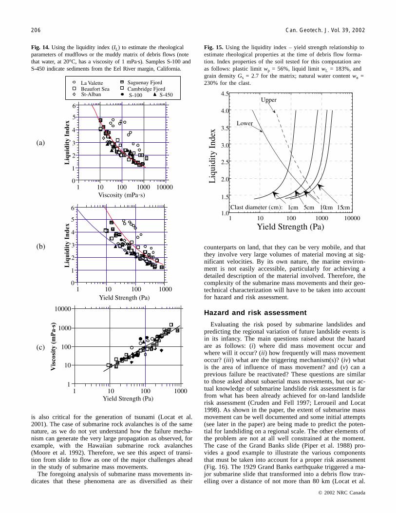
In many cases, we consider the mixture as a yield stressfluid, so the rheological behaviour of the matrix can be rep-resented by a yield strength and a viscosity parameter. It hasbeen proposed that the yield strength and viscosity could berelated to the liquidity index (IL) (Locat and Demers 1988;Locat 1997) for as long as the liquidity index is greater than0 (i.e., for a water content above the plastic limit). Resultsobtained for various soils or sediments are given in Fig. 14.The results are partly influenced by the floc size and by sa-linity in the case of the yield strength (Locat 1997). Never-theless, for a single sediment or soil, the quality of therelationship is quite reasonable. An interesting observation,obtained from laboratory testing, is that the yield strengthcontributes about 1000 times more than the viscosity to theresistance to flow of the fluid. The results in Fig. 14 can beused hereafter to provide a first approximation of the rela-tionships between liquidity index and rheological parameters(see also Locat 1997):
[6] η =
9.27
L
3.3
I
[7] τ cL
4.555.81=
I
for a pore-water salinity of about 0 g/L;
[8] τ cL
3.1312.05=
I
for a pore-water salinity of about 30 g/L; and
[9] η τ= 0.52 c1.12
where η is in mPa·s and τ in Pa.Recently, these relationships have been used successfully by
Elverhoi et al. (1997) to analyse the behaviour of debris flowsalong the coast of Norway. For mudflows or matrix-controlleddebris flows, Hampton (1972) has shown that the minimumthickness of the flowing material (Hc, in m) for flow to takeplace can be defined by the following relationship:
[10] Hcc=
′
τ
γ βsin
where γ ′ is the submerged unit weight in kN/m3 (not to beconfused here with the shear rate in fluid mechanics), and βis the slope angle (note that τc is given in kPa). Modifyingeq. [8], for seawater, and considering τc in kPa,
[11] τ c L–3.132.42= I
© 2002 NRC Canada
204 Can. Geotech. J. Vol. 39, 2002
Fig. 12. Schematic view of far-reaching debris flows depositedon the Mississippi Fan (modified after Twichell et al. 1991).
I:\cgj\Cgj39\Cgj-01\T01-089.vpFriday, February 15, 2002 1:23:43 PM
Color profile: DisabledComposite Default screen
we can rewrite eq. [10] partly as a function of the liquidityindex:
[12] HI
cL–3.13
w
2.42=−( ) sinγ γ β
where γ and γw are the total unit weight of the sediment andwater, respectively. Equation [12] is a generalization of theapproach already proposed by Schwab et al. (1996) for de-bris flows in the Gulf of Mexico to estimate the critical flowheight from easily determined physical parameters. Ineq. [12], all parameters can be obtained easily from coresand even on remoulded samples, so the liquidity index canbe measured easily as can the bulk density (often obtainedfrom multisensor track (MST) logging).
The liquidity index – yield strength relationship can also beused to back-calculate the yield strength of a debris flow at thetime of the event for as long as the water content of the clast isgreater than that for the matrix (Fig. 15). This assumes that noconsolidation of the clast took place since deposition. Such anapproach, based on the work of Hampton (1975), has beenused successfully by Schwab et al. (1996) to analyse the mobil-ity of debris flows on the Mississippi Fan. Hampton (1975)considers the mixture like a Bingham fluid, so the largest di-ameter of the clast (Dmax) which can be supported by theclay–water slurry is calculated using the following relationship:
[13] Dg
maxc
c m
8.8=−′ ′τ
γ γ( )
where g is the acceleration due to gravity; and γc′ and γm′ arethe submerged unit weights of the clast and the matrix, re-spectively (adapted from Schwab et al. 1996). The use ofeq. [13] could also be another way of estimating the liquid-ity index, at the time of the mudflow event, using eqs. [7]and [8].
Coupling many of the above relationships, we analysedmuddy, clayey sediments containing clay clasts to develop achart that can be used to restrain the approximation of the
rheological parameters at the time of the mudflow event.This is illustrated by the results displayed in Fig. 15 for sedi-ments from the Black Sea, with their physical properties asindicated in the figure caption. We have represented the twoextreme curves (upper and lower) relating the liquidity indexand the yield strength (from eqs. [7] and [8]) which providea realistic range of values for both liquidity index and yieldstrength. Also shown in Fig. 15 is the computation ofeq. [13] for different values of Dmax (here given in centi-metres). For example, if the maximum observed clast diame-ter is 10 cm (with physical properties as indicated in thefigure caption), the only possible ranges of liquidity indexand yield strength values of the matrix would have to fall in-side the area bounded by the so-called upper and lowercurves. Moreover, if for a given sediment the relationshipbetween IL and τc has been obtained directly using a visco-meter, then the potential range of values can be greatlyreduced. The end result can be quite useful in trying to de-termine the rheological conditions under which a mudflowor a debris flow has taken place (provided that the watercontent of the clast has not changed since deposition, orcould be estimated properly).
We have shown that it is possible, at least for sediments, toanalyse the mobility of sediments and obtain, or estimatefrom the liquidity index, the various parameters necessary forusing the various flow models. One of the key question here,which is also true for on-land mass movements, is how doesthe material acquire these physical (rheological) properties?For example, Locat et al. (1996) indicated that the mobilizedyield strength (or remoulded shear strength) back-calculatedfor the Gulf of Mexico debris flows was up to three orders ofmagnitude lower than the minimum remoulded shear strengthmeasured in the potential source area today. There must besome mechanical processes taking place during the transitionfrom failure to post-failure which generate significant vol-umes of a mixture having a very low remoulded shearstrength. This transition phase from slide to flow, which canbe accompanied with some acceleration of the moving mass,
© 2002 NRC Canada
Locat and Lee 205
Fig. 13. Schematic diagram showing the generation of a turbidity current (suspension flow) for drag forces on the surface, potentiallifting of frontal lobe leading to the process of hydroplaning, the basal shear stress causing erosion, and deposition. g, acceleration dueto gravity.
I:\cgj\Cgj39\Cgj-01\T01-089.vpFriday, February 15, 2002 1:23:46 PM
Color profile: DisabledComposite Default screen
is also critical for the generation of tsunami (Locat et al.2001). The case of submarine rock avalanches is of the samenature, as we do not yet understand how the failure mecha-nism can generate the very large propagation as observed, forexample, with the Hawaiian submarine rock avalanches(Moore et al. 1992). Therefore, we see this aspect of transi-tion from slide to flow as one of the major challenges aheadin the study of submarine mass movements.
The foregoing analysis of submarine mass movements in-dicates that these phenomena are as diversified as their
counterparts on land, that they can be very mobile, and thatthey involve very large volumes of material moving at sig-nificant velocities. By its own nature, the marine environ-ment is not easily accessible, particularly for achieving adetailed description of the material involved. Therefore, thecomplexity of the submarine mass movements and their geo-technical characterization will have to be taken into accountfor hazard and risk assessment.
Hazard and risk assessment
Evaluating the risk posed by submarine landslides andpredicting the regional variation of future landslide events isin its infancy. The main questions raised about the hazardare as follows: (i) where did mass movement occur andwhere will it occur? (ii) how frequently will mass movementoccur? (iii) what are the triggering mechanism(s)? (iv) whatis the area of influence of mass movement? and (v) can aprevious failure be reactivated? These questions are similarto those asked about subaerial mass movements, but our ac-tual knowledge of submarine landslide risk assessment is farfrom what has been already achieved for on-land landsliderisk assessment (Cruden and Fell 1997; Leroueil and Locat1998). As shown in the paper, the extent of submarine massmovement can be well documented and some initial attempts(see later in the paper) are being made to predict the poten-tial for landsliding on a regional scale. The other elements ofthe problem are not at all well constrained at the moment.The case of the Grand Banks slide (Piper et al. 1988) pro-vides a good example to illustrate the various componentsthat must be taken into account for a proper risk assessment(Fig. 16). The 1929 Grand Banks earthquake triggered a ma-jor submarine slide that transformed into a debris flow trav-elling over a distance of not more than 80 km (Locat et al.
© 2002 NRC Canada
206 Can. Geotech. J. Vol. 39, 2002
Fig. 14. Using the liquidity index (IL) to estimate the rheologicalparameters of mudflows or the muddy matrix of debris flows (notethat water, at 20°C, has a viscosity of 1 mPa·s). Samples S-100 andS-450 indicate sediments from the Eel River margin, California.
Fig. 15. Using the liquidity index – yield strength relationship toestimate rheological properties at the time of debris flow forma-tion. Index properties of the soil tested for this computation areas follows: plastic limit wp = 56%, liquid limit wL = 183%, andgrain density Gs = 2.7 for the matrix; natural water content wn =230% for the clast.
I:\cgj\Cgj39\Cgj-01\T01-089.vpFriday, February 15, 2002 1:23:48 PM
Color profile: DisabledComposite Default screen
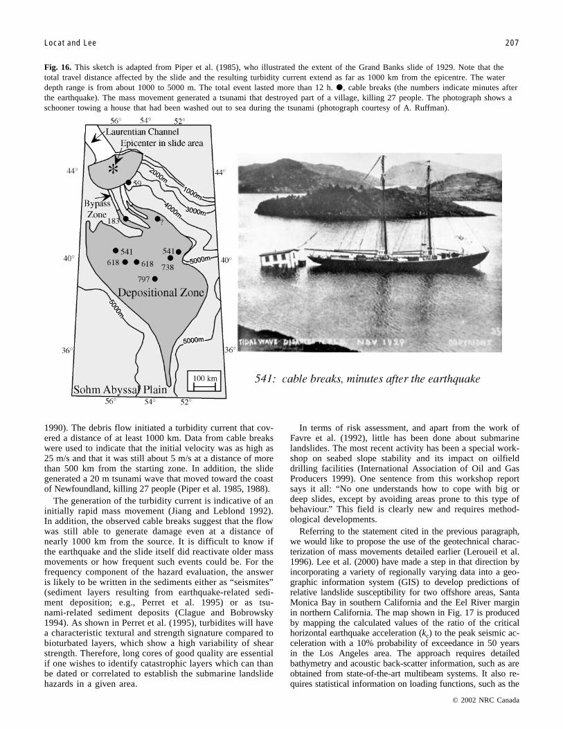
1990). The debris flow initiated a turbidity current that cov-ered a distance of at least 1000 km. Data from cable breakswere used to indicate that the initial velocity was as high as25 m/s and that it was still about 5 m/s at a distance of morethan 500 km from the starting zone. In addition, the slidegenerated a 20 m tsunami wave that moved toward the coastof Newfoundland, killing 27 people (Piper et al. 1985, 1988).
The generation of the turbidity current is indicative of aninitially rapid mass movement (Jiang and Leblond 1992).In addition, the observed cable breaks suggest that the flowwas still able to generate damage even at a distance ofnearly 1000 km from the source. It is difficult to know ifthe earthquake and the slide itself did reactivate older massmovements or how frequent such events could be. For thefrequency component of the hazard evaluation, the answeris likely to be written in the sediments either as “seismites”(sediment layers resulting from earthquake-related sedi-ment deposition; e.g., Perret et al. 1995) or as tsu-nami-related sediment deposits (Clague and Bobrowsky1994). As shown in Perret et al. (1995), turbidites will havea characteristic textural and strength signature compared tobioturbated layers, which show a high variability of shearstrength. Therefore, long cores of good quality are essentialif one wishes to identify catastrophic layers which can thanbe dated or correlated to establish the submarine landslidehazards in a given area.
In terms of risk assessment, and apart from the work ofFavre et al. (1992), little has been done about submarinelandslides. The most recent activity has been a special work-shop on seabed slope stability and its impact on oilfielddrilling facilities (International Association of Oil and GasProducers 1999). One sentence from this workshop reportsays it all: “No one understands how to cope with big ordeep slides, except by avoiding areas prone to this type ofbehaviour.” This field is clearly new and requires method-ological developments.
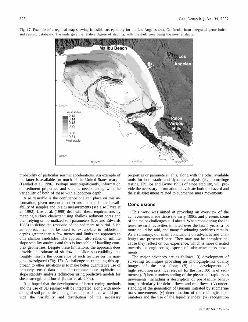
Referring to the statement cited in the previous paragraph,we would like to propose the use of the geotechnical charac-terization of mass movements detailed earlier (Leroueil et al.1996). Lee et al. (2000) have made a step in that direction byincorporating a variety of regionally varying data into a geo-graphic information system (GIS) to develop predictions ofrelative landslide susceptibility for two offshore areas, SantaMonica Bay in southern California and the Eel River marginin northern California. The map shown in Fig. 17 is producedby mapping the calculated values of the ratio of the criticalhorizontal earthquake acceleration (kc) to the peak seismic ac-celeration with a 10% probability of exceedance in 50 yearsin the Los Angeles area. The approach requires detailedbathymetry and acoustic back-scatter information, such as areobtained from state-of-the-art multibeam systems. It also re-quires statistical information on loading functions, such as the
© 2002 NRC Canada
Locat and Lee 207
Fig. 16. This sketch is adapted from Piper et al. (1985), who illustrated the extent of the Grand Banks slide of 1929. Note that thetotal travel distance affected by the slide and the resulting turbidity current extend as far as 1000 km from the epicentre. The waterdepth range is from about 1000 to 5000 m. The total event lasted more than 12 h. �, cable breaks (the numbers indicate minutes afterthe earthquake). The mass movement generated a tsunami that destroyed part of a village, killing 27 people. The photograph shows aschooner towing a house that had been washed out to sea during the tsunami (photograph courtesy of A. Ruffman).
I:\cgj\Cgj39\Cgj-01\T01-089.vpFriday, February 15, 2002 1:23:55 PM
Color profile: DisabledComposite Default screen
probability of particular seismic accelerations. An example ofthe latter is available for much of the United States margin(Frankel et al. 1996). Perhaps most significantly, informationon sediment properties and state is needed along with thevariability of both of these with subbottom depth.
Also desirable is the confidence one can place on this in-formation, given measurement errors and the limited avail-ability of samples and in situ measurements (see also Favre etal. 1992). Lee et al. (1999) deal with these requirements bymapping surface character using shallow sediment cores andthen relying on normalized soil parameters (Lee and Edwards1986) to define the response of the sediment to burial. Suchan approach cannot be used to extrapolate to subbottomdepths greater than a few metres and limits the approach toonly shallow landslides. The approach also relies on infiniteslope stability analysis and thus is incapable of handling com-plex geometries. Despite these limitations, the approach doesprovide an estimate of shallow landslide susceptibility thatroughly mirrors the occurrence of such features on the mar-gins investigated (Fig. 17). A challenge to extending this ap-proach to other situations is to make better quantitative use ofremotely sensed data and to incorporate more sophisticatedslope stability analysis techniques using predictive models forshear strength and burial (Locat et al. 2002).
It is hoped that the development of better coring methodsand the use of 3D seismic will be integrated, along with mod-elling of soil properties, in a general approach that would pro-vide the variability and distribution of the necessary
properties or parameters. This, along with the other availabletools for both static and dynamic analysis (e.g., centrifugetesting; Phillips and Byrne 1995) of slope stability, will pro-vide the necessary information to evaluate both the hazard andthe risk assessment related to submarine mass movements.
Conclusions
This work was aimed at providing an overview of theachievements made since the early 1990s and presents someof the major challenges still ahead. When considering the in-tense research activities initiated over the last 5 years, a lotmore could be said, and many fascinating problems remain.As a summary, our main conclusions on advances and chal-lenges are presented here. They may not be complete be-cause they reflect on our experience, which is more orientedtowards the engineering aspects of submarine mass move-ments.
The major advances are as follows: (i) development ofsurveying techniques providing air photograph-like qualityimages of the sea floor; (ii) the development ofhigh-resolution seismics relevant for the first 100 m of sedi-ments; (iii) better understanding of the physics of rapid massmovements, including a description of post-failure behav-iour, particularly for debris flows and mudflows; (iv) under-standing of the generation of tsunami initiated by submarinemass movements; (v) determination of the rheological pa-rameters and the use of the liquidity index; (vi) recognition
© 2002 NRC Canada
208 Can. Geotech. J. Vol. 39, 2002
Fig. 17. Example of a regional map showing landslide susceptibility for the Los Angeles area, California, from integrated geotechnicaland seismic databases. The units give the relative degree of stability, with the dark zone being the most unstable.
I:\cgj\Cgj39\Cgj-01\T01-089.vpFriday, February 15, 2002 1:24:01 PM
Color profile: DisabledComposite Default screen
of the role of gas hydrates in the development of slope insta-bility; and (vii) introduction of the concept of hydroplaningto explain some of the large run-out distances achieved bydebris flows or mudflows.
The major challenges are as follows: (i) improving sedi-ment sampling and in situ measurement techniques; (ii) in-tegrating 3D seismic methods into slope stability analysis;(iii) use of long cores to provide estimates of the frequencyof catastrophic events in the aquatic environment; (iv) iden-tifying and understanding the physical processes involvedin the transition from failure to post-failure for a better pre-diction of the initial acceleration of the moving mass andthe ongoing modifications of its physical properties leadingto the acquisition of a fluid-like behaviour; (v) hazard as-sessment, particularly frequency and extent; (vi) monitoringthe movement and mobilization of actual landslides; (vii)determining the role of subsurface water flow in initiatingsubmarine landslides; (vii) integrating the role of gas hy-drates in the analysis and prediction of submarine slopestability; (viii) evaluating the mechanics of giant submarinelandslides and improving our understanding of the causesof their great run-out distances; and (ix) developing criteriato determine the cause of sea-floor deposits that have beendescribed as either landslides or migrating sediment waves.
Acknowledgements
The authors would like to thank the following organisationsfor providing the financial support for carrying out researchon submarine mass movements: the United States GeologicalSurvey, the Québec Ministry of Education, the U.S. Office ofNaval Research, the Natural Sciences and Engineering Re-search Council of Canada, the Fonds FCAR of the Ministryof Education of Québec, and the Geological Survey of Can-ada. We also thank Dr. Roger Urgeles and the two anonymousreviewers for their constructive criticisms of the manuscriptand for their interesting comments. Many of the ideas pre-sented herein also result from the many stimulating discus-sions we had, and still have, with many colleagues around theWorld, and particularly those involved in projects likeSTRATAFORM, EuroSTRATAFORM, and COSTA.
References
Bea, R.G., Wright, S.G., Sircar, P., and Niedoroda, A.W. 1983.Wave-induced slides in South Pass Block 70, Mississippi Delta.Journal of Geotechnical Engineering, ASCE, 109: 619–644.
Bellaiche, G. 1993. Sedimentary mechanisms and underlying tec-tonic structures of the north-western Mediterranean margin, asrevealed by comprehensive bathymetric and seismic surveys.Marine Geology, 112: 89–108.
Bohannon, R.G., and Gardner, J.V. 2001. Submarine landslides atSan Pedro Valley, Southwest Los Angeles Basin. In Proceedingsof the Workshop on the Prediction of Underwater Landslidesand Slump Occurrence and Tsunami Hazards off of SouthernCalifornia, Los Angeles, 10–11 March 2000. Edited by P. Watts.A.A. Balkema, Rotterdam. In press.
Boulanger, E. 2000. Comportement cyclique des sédiments de lamarge continentale de la rivière Eel: une explication possiblepour le peu de glissements sous-marins superficiels dans cette
région. M.Sc. thesis, Department of Geology and GeologicalEngineering, Laval University, Sainte-Foy, Que.
Boulanger, E., Konrad, J.-M., Locat, J., and Lee, H.J. 1998.Cyclic behavior of Eel River sediments: a possible explana-tion for the paucity of submarine landslide features. Ameri-can Geophysical Union San Francisco, EOS, Abstract. Vol.79, pp. 254.
Bouriak, S., Vanneste, M., and Saoutkine, A. 2000. Inferred gashydrates and clay diapirs near the Storegga slide on the southernedge of the Voring Plateau, offshore Norway. Marine Geology,163(1–4): 125–148.
By, T., Forsberg, C.F., and Norem, H. 1990. Submarine slides: fullscale experiment at Storglomvatn, Norway. Norwegian Geo-technical Institute, Report 522090-4.
Christian, H.A., Heffler, D.E., and Davis, E.E. 1993. Lancelot: anin situ piezometer for soft marine sediments. Deep Sea Re-search, 7: 1509–1520.
Christian, H.A., Mulder, T., Courtney, R.C., Mosher, D.C., Barrie,J.V., Currie, R.G., Olynyk, H.W., and Monahan, P.A. 1994. Slopestability on the Fraser River delta foreslope, Vancouver, BritishColumbia. In Proceedings of the 47th Canadian GeotechnicalConference, Halifax, pp. 155–165.
Clague, J.J., and Bobrowsky, P.T. 1994. Tsunami deposits beneathtidal marshes on Vancouver island, British Columbia. Geologi-cal Society of America Bulletin, 106: 1293–1302.
Cornforth, D.H., and Lowell, J.A. 1996. The 1994 submarine slopefailure at Skagway, Alaska. In Proceedings of the 7th Interna-tional Symposium on Landslides. Edited by K. Senneset. A.A.Balkema, Rotterdam, Vol. 1, pp. 527–532.
Coussot, P., and Piau, J.-M. 1994. On the behavior of fine mud sus-pension. Rheologica Acta, 33: 175–184.
Couture, R., Locat, J., Godin, A., Therrien, P., Messager, S., andBabineau, S. 1993. Relevés bathymétriques au fjord duSaguenay à l’aide de l’écho-sondeur multifaisceaux SIMRADEM-1000, Expédition à bord du F.G. Creed. Department of Ge-ology and Geological Engineering, Laval University, Sainte-Foy,Que., Report GREGI 93-16.
Couture, R., Konrad, J.-M., and Locat, J. 1995. Analyse de laliquéfaction et du comportement non drainé des sables du deltade Kenamu (Projet ADFEX). Canadian Geotechnical Journal,32: 137–155.
Cruden, D.M., and Fell, R. (Editors). 1997. Landslide risk assess-ment. A.A. Balkema, Rotterdam.
Davies, T.A., and Austin, J.A., Jr. 1997. High-resolution 3D seis-mic reflection and coring techniques applied to Quaternary de-posits on the New Jersey Shelf. Marine Geology, 143: 137–149.
Davies, T.R., McSaveney, M.J., and Hodgson, K.A. 2000. A frag-mentation-spreading model for long run-out rock avalanches.Canadian Geotechnical Journal, 36: 1096–1110.
Driscoll, N.W., and Kramer, G.D. 1999. Three-dimensional quantita-tive modeling of clinoform development. Marine Geology, 154:383–398.
Driscoll, N.W., Weissel, J.K., and Goff, J.A. 2000. Potential forlarge-scale submarine slope failure and tsunami generation alongthe U.S. mid-Atlantic coast. Geology, 28(5): 407–410.
Edgers, L., and Karlsrud, K. 1982. Soil flows generated by submarineslides: case studies and consequences. In Proceedings of the 3rdInternational Conference on the Behavior of Offshore Structures.Edited by C. Chryssostomomidis and J.J. Connor. HemispherePublishing Corporation. Vol. 2, pp. 425–437.
Elsworth, D., and Voight, B. 1995. Dike intrusion as a trigger forlarge earthquakes and the failure of volcano flanks. Journal ofGeophysical Research, 100: 6005–6024.
© 2002 NRC Canada
Locat and Lee 209
I:\cgj\Cgj39\Cgj-01\T01-089.vpFriday, February 15, 2002 1:24:01 PM
Color profile: DisabledComposite Default screen
Elverhoi, A., Norem, H., Andersen, E.S., Dowdeswell, J.A., Fossen,I., Haflidason, H., Kenyon, N.H., Laberg, J.S., King, E.L., Sejrup,H.P., Solheim, A., and Vorren, T. 1997. On the origin and flow be-havior of submarine slides on deep-sea fans along the Norwegian –Barents Sea continental margin. Geo-Marine Letters, 17: 119–125.
Embley, R.W. 1976. New evidence for the occurrence of debrisflow deposits in the deep sea. Geology, 4: 371–374.
Embley, R.W. 1982. Anatomy of some Atlantic margin sedimentslides and some comments on ages and mechanisms. In Marineslides and other mass movements. Edited by S. Saxov and J.K.Nieuwenhuis. Plenum Press, New York, pp. 189–214.
Embley, R.W., Rabinowitz, P.D., and Jacobi, R.D. 1978. Hyper-bolic echo zones in the Eastern Atlantic and the structure of theSouthern Madeira Rise. Earth and Planetary Science Letters, 41:419–433.
Favre, J.L., Barakat, B., Yoon, S.H., and Franchomme, O. 1992.Modèle de risque de glissements de fonds marins. In Proceed-ings of the 6th International Symposium on Landslides. Editedby D.H. Bell. A.A. Balkema, Rotterdam, pp. 937–942.
Flon, P. 1982. Énergie de remaniement et régression des couléesd’argiles. M.Sc. thesis, Department of Civil Engineering, LavalUniversity, Sainte-Foy, Que.
Frankel, A., Mueller, C., Barnhard, T., Perkins, D., Leyendecker,E.V., Dickman, N., Hanson, S., and Hopper, M. 1996. Nationalseismic-hazard maps: documentation, June 1996. U.S. Geologi-cal Survey, Open-file Report 96-532.
Gorsline, D.S., Kolpack, R.L., Karl, H.A., Drake, D.E., Fleischer,P., Thornton, S.E., Schwalbach, J.R., and Savrda, C.E. 1984.Studies of fine-grained sediment transport processes and prod-ucts in the California Continental Borderland. In Fine-grainedsediments: deep water processes and facies. Edited by D.A.V.Stow and D.J.W. Piper. Blackwell Scientific Publications Ltd.,Oxford, pp. 395–415.
Hampton, M.A. 1972. The role of subaqueous debris flows in gen-erating turbidity currents. Journal of Sedimentary Petrology, 42:775–793.
Hampton, M.A. 1975. Competence of fine debris flows. Journal ofSedimentary Petrology, 45: 834–844
Hampton, M.A., Lee, H.J., and Beard, R.M. 1982. Geological in-terpretation of cone penetrometer tests in Norton Sound, Alaska.Geo-Marine Letters, 2(3–4): 223–231.
Hampton, M.A., Lee, H.J., and Locat, J. 1996. Submarine land-slides. Reviews of Geophysics, 34: 33–59.
Harbitz, C.B. 1992. Model simulations of tsunamis generated bythe Storegga slides. Marine Geology, 105: 1–21.
Hart, B. 1999. Definitions of subsurface stratigraphy, structure androck properties from 3-D seismic data. Earth-Science Reviews,47: 189–218.
Heim, A. 1932. Bergstruz und Menschenleben. Fretz und WasmuthVerlag, Zurich.
Holcomb, R.T., and Searle, R.C. 1991. Large landslides from oce-anic volcanoes. Marine Geotechnology, 10: 19–32.
Huang, X., and Garcia, M.H. 1999. Modeling of non-hydroplaningmudflows on continental slopes. Marine Geology, 154: 131–142.
Hughes Clarke, J.E., Mayer, L.A., and Wells, D.E. 1996. Shal-low-water imaging multibeam sonars: a new tool for investigat-ing seafloor processes in the coastal zone and on the continentalshelf. Marine Geophysical Researches, 18: 607–629.
Hutchinson, J.N. 1986. A sliding-consolidation model for flow slides.Canadian Geotechnical Journal, 23: 115–126.
Hutchinson, J.N. 1988. Morphology and geotechnical parametersof landslides in relation to geology and hydrogeology. In Pro-ceedings of the 5th International Symposium on Landslides,Lausanne, Vol. 1, pp. 3–35.
Imran, J., Parker, G., Locat, J., and Lee, H.J. 2001. 1-D numericalmodel of muddy subaqueous and subaerial debris flows. Jour-nals of Hydraulic Engineering, ASCE, 127(11): 959–968.
International Association of Oil and Gas Producers. 1999. OGPWorkshop on Seabed Slope Stability and its Impact on OilfieldDrilling and Facilities. Report 3.16/298, International Associa-tion of Oil and Gas Producers, London.
Iverson, R.M. 1997. The physics of debris flows. Reviews of Geo-physics, 35: 245–296.
Jiang, L., and Leblond, P.H. 1992. The coupling of a submarineslide and the surface waves which it generates. Journal of Geo-physical Research, 97: 12 731 – 12 744.
Johnson, A.M. 1970. Physical processes in geology. W.H. Free-man, New York.
Kammerer, E., Hughes Clarke, J.E., Locat, J., Doucet, N., andGodin, A. 1998. Monitoring temporal changes in seabed mor-phology and composition using multibeam sonars: a case studyof the 1996 Saguenay River floods. In Proceedings of the Cana-dian Hydrographic Conference, Victoria. pp. 450–461.
Kayen, R.E., and Lee, H.J. 1991. Pleistocene slope instability ofgas hydrate-laden sediment on the Beaufort Sea margin. MarineGeotechnology, 10: 125–141.
Kristiansen, J. 1986. Blast-induced liquefaction of soils, a refer-ence search. Norwegian Geotechnical Institute, Report 52209-1.
Kulikov, E.A., Rabinivich, A.B., Thomson, R.E., and Bornhold, B.1996. The landslide tsunami of November 3, 1994, SkagwayHarbour, Alaska. Journal of Geophysical Research, 101(C3):6609–6615.
Kulikov, E.A., Rabinivich, A.B., Fine, I.V., Bornhold, B., andThomson, R.E. 1998. Tsunami generation by landslides at the Pa-cific coast of North America and the role of tides. Oceanology,38(3): 323–328.
Kvenvolden, K.A., and McMenamin, M.A. 1980. Hydrates of natu-ral gas: a review of their geological occurrence. U.S. GeologicalSurvey, Circular 825.
Laval, A., Cremer, M., Beghin, P., and Ravenne, C. 1988. Densitysurges: two-dimensional experiments. Sedimentology, 35: 73–84.
Lebuis, J., Robert, J.-M., and Rissmann, P. 1983. Regional map-ping of landslide hazard in Québec. In Symposium on Slopes inSoft Clays, Linkoping, Sweden. Swedish Geotechnical Institute,Report 17, pp. 205–262.
Lee, H.J. 1989. Undersea landslides: extent and significance in thePacific Ocean. In Proceedings of the 28th International Geologi-cal Conference, Washington. Vol. 2, pp. 275–276.
Lee, H.J. (Editor). 1991. Special issue on submarine slope stability.Marine Geotechnology, 10(1–2).
Lee, H.J., and Edwards, B.D. 1986. Regional method to assess off-shore slope stability. Journal of Geotechnical Engineering, ASCE,112: 489–509.
Lee, H.J., Schwab, W.C., Edwards, B.D., and Kayen, R.E. 1991.Quantitative controls on submarine slope failure morphology.Marine Geotechnology, 10(1/2): 143–158.
Lee, H.J., Locat, J., Dartnell, P., Israel, K., and Wong, F. 1999. Re-gional variability of slope stability: application to the Eel mar-gin, California. Marine Geology, 154: 305–321.
Lee, H.J., Locat, J., Dartnell, P., Minasian, D., and Wong, F. 2000. AGIS-based regional analysis of the potential for shallow-seatedsubmarine slope failures. In Proceedings of the 8th InternationalSymposium on Landslides, Cardiff, U.K., pp. 917–922.
Leroueil, S., and Locat, J. 1998. Slope movements — geotechnicalcharacterization, risk assessment and mitigation. In Proceedingsof the 11th Danube European Conference on Soil Mechanicsand Geotechnical Engineering, Porec, Croatia, pp. 95–106.
© 2002 NRC Canada
210 Can. Geotech. J. Vol. 39, 2002
I:\cgj\Cgj39\Cgj-01\T01-089.vpFriday, February 15, 2002 1:24:02 PM
Color profile: DisabledComposite Default screen
Leroueil, S., Vaunat, J., Picarelli, L., Locat, J., Lee, H., and Faure,R. 1996. Geotechnical characterization of slope movements. InProceedings of the International Symposium on Landslides,Trondheim. Vol. 1, pp. 53–74.
Li, C., and Clark, A.L. 1991. SeaMarc II study of a giant subma-rine slump on the Northern Chile Continental Slope. MarineGeotechnology, 10: 257–268.
Lipman, P.W., Lockwood, J.P., Okamura, R.T., Swanson, D.A., andYamashita, K.M. 1985. Ground deformation associated with the1975 magnitude-7.2 earthquake and resulting changes in activityof Kilauea volcano, Hawaii. U.S. Geological Survey, Profes-sional Paper 1276.
Locat, J. 1997. Normalized rheological behavior of fine muds andtheir flow properties in a pseudoplastic regime. In Debris-flowhazards mitigation: mechanics, prediction, and assessment. Wa-ter Resources Engineering Division, American Society of CivilEngineers, New York, pp. 260–269.
Locat, J. 2001. Instabilities along ocean margins: a geomorphologicaland geotechnical perspective. Marine and Petroleum Geology,18(4): 503–512.
Locat, J., and Bergeron, M. 1988. Étude à rebours de glissementssous-marins, fjord du Saguenay,Québec. In Proceedings of the 41stCanadian Geotechnical Conference, Waterloo, Ont., pp. 338–346.
Locat, J., and Demers, D. 1988. Viscosity, yield stress, remoldedstrength, and liquidity index relationships for sensitive clays.Canadian Geotechnical Journal, 25: 799–806.
Locat, J., and Leroueil, S. 1988. Physicochemical and geotechnicalcharacteristics of recent Saguenay Fjord sediments. CanadianGeotechnical Journal, 25: 382–388.
Locat, J., and Sanfaçon, R. 2000. Multibeam surveys: a major toolfor geosciences. In Proceedings of the Canadian HydrographicSociety, Montréal, CD-ROM, ISBN 2-9802836-9-X.
Locat, J., Norem, H., and Schieldrup, N. 1990. Modélisation de ladynamique des glissements sous-marins. In Proceedings of the6th Congress of the International Association of EngineeringGeology, Amsterdam, pp. 2849–2855.
Locat, J., Lee, H.J., Nelson, H.C., Schwab, W.C., and Twichell, D.C.1996. Analysis of the mobility of far reaching debris flows on theMississippi Fan, Gulf of Mexico. In Proceedings of the 7th Inter-national Symposium on Landslides. Edited by K. Senneset. A.A.Balkema, Rotterdam, pp. 555–560.
Locat, J., Gardner, J.V., Lee, H., Mayer, L., Hughes-Clarke, J.E., andKammerer, E. 1999. Using multibeam surveys for submarine land-slide investigations. In Proceedings of the International Symposiumon Slope Stability Engineering. Edited by N. Yagi, T. Yamagami,and J.-C. Jiang. A.A. Balkema, Rotterdam, pp. 127–134.
Locat, J., Lee, H.J., and Locat, P. 2001. Analysis of the PalosVerdes Slide, California, and its implication for the generationof tsunamis. In Proceedings of the Workshop on the Predictionof Underwater Landslides and Slump Occurrence and TsunamiHazards off of Southern California. Edited by P. Watts. A.A.Balkema, Rotterdam. In press.
Locat, J., Lee, H.J., Kayen, R., Savoie, M.-C., and Boulanger, E.2002. Shear strength development with burial in Eel River Marginslope sediments. Marine Geotechnology and Resources. In press.
Locat, J., Urgeles, R., Schmitt, T., Martin, F., Hoareau, L., Hill, P.,Long, B., Simpkin, P., Kammerer, E., and Sanfaçon, R. 2000.The morphological signature of natural disasters in the UpperSaguenay Fjord area, Québec, Canada. In Proceedings of the53rd Canadian Geotechnical Conference, Montréal, Vol. 1,pp. 109–116.
Masson, D.G., Kidd, R.B., Gardner, J.V., Hugget, Q.J., andWeaver, P.P.E. 1992. Saharan continental rise: facies distributionand sediment slides. In A geologic evolution of Atlantic conti-
nental rises. Edited by C.W. Poagi and P.C. de Graciansky. VanNostrand Reinhold, New York, pp. 327–343.
Masson, D.G., Hugget, Q.J., and Brunsden, D. 1993. The surfacetexture of the Saharan debris flow and some speculations onsubmarine debris flow processes. Sedimentology, 40: 583–598.
Masson, D.G., Canals, M., Alonso, B., Urgeles, R., and Huhnerbach,V. 1998. The Canary debris flow: source area morphology andfailure mechanisms. Sedimentology, 45: 411–432.
Mitchell, N.C. 1991. Improving GLORIA images using SeaBeamdata. Journal of Geophysical Research, 96: 337–351.
Mitchell, R.J., and Markell, A.R. 1974. Flowslides in sensitivesoils. Canadian Geotechnical Journal, 11: 11–31.
Meunier, M. 1993. Classification of streams flows. In Proceedings ofthe Pierre Beghin International Workshop on Rapid GravitationalMass Movements, CEMAGREF, Grenoble, France, pp. 231–236.
Mohrig, D., Elverhoi, A., and Parker, G. 1999. Experiments on therelative mobility of muddy subaqueous and subaerial debris flows,and their capacity to remobilize antecedent deposits. Marine Geol-ogy, 154: 117–129.
Moore, J.G., and Normark, W.R. 1994. Giant Hawaiian landslides.Annual Reviews in Earth and Planetary Sciences, 22: 119–144.
Moore, J.G., Normark, W.R., and Gutmacher, C.E. 1992. Majorlandslides on the submarine flanks of Mauna Loa volcano, Ha-waii. Landslide News, 6: 13–16.
Moore, J.G., Bryan, W.B., Beeson, M.H., and Normark, W.R. 1995.Giants blocks in the South Kona landslide, Hawaii. Geology, 23:125–128.
Morgenstern, N.R. 1967. Submarine slumping and the initiation ofturbidity currents. In Marine geotechnique. Edited by A.F. Rich-ards. University of Illinois Press, Urbana, Ill., pp. 189–210.
Mulder, T., and Cochonat, P. 1996. Classification of offshore massmovements. Journal of Sedimentary Research, 66: 43–57.
Mulder, T., and Moran, K. 1995. Relationship among submarineinstabilities, sea-level variations and the presence of an ice sheeton the continental shelf: an example from the Verrill Canyonarea, Scotian Shelf. Paleoceanography, 10: 137–154.
Mulder, T., and Syvitski, J.P.M. 1995. Turbidity currents generated atriver mouths during exceptional discharges to the world oceans.Journal of Geology, 103: 285–299.
Mulder, T., Tisot, J.-P., Cochonat, P., and Bourillet, J.-F. 1993.Stabilité des pentes sous-marines dans la Baie des Anges, Nice,France: approche géotechnique. Revue Française de Géotechnique,64: 21–30.
Nittrouer, C.A. 1999. STRATAFORM: overview of its design andsynthesis of its results. Marine Geology, 154: 3–12.
Norem, H., Locat, J., and Schieldrop, B. 1990. An approach to thephysics and the modelling of submarine landslides. Marine Geo-technology, 9: 93–111.
Normark, W.R., and Piper, D.J.W. 1991. Initiation processes andflow evolution of turbidity currents: implications for thedepositional record. In From shoreline to abyssal. Society of Eco-nomic Paleontologists and Mineralogists, Special Publication 46,Edited by R.H. Osborne. pp. 20–230.
O’Brien, J.S., and Julien, P.Y. 1988. Laboratory analysis of mud-flow properties. Journal of Hydraulics Engineering, ASCE, 114:877–887.
O’Leary, D.W. 1993. Submarine mass movement, a formative pro-cess of passive continental margins: the Munsen-Nygren landslidecomplex and the southeast New England landslide complex. InSubmarine landslides: selected studies in the U.S. Exclusive Eco-nomic Zone. Edited by W.C. Schwab, H.J. Lee, and D. Twichell.U.S. Geological Survey, Bulletin 2002, pp. 23–39.
Orange, D.L., and Breen, N.A. 1992. The effects of fluid escape onaccretionary wedges II: seepage force, slope failure, headless
© 2002 NRC Canada
Locat and Lee 211
I:\cgj\Cgj39\Cgj-01\T01-089.vpFriday, February 15, 2002 1:24:02 PM
Color profile: DisabledComposite Default screen
© 2002 NRC Canada
212 Can. Geotech. J. Vol. 39, 2002
submarine canyons and vents. Journal of Geophysical Research,97: 9277–9295.
Orange, D.L., McAdoo, B.G., Moore, J.C., Tobin, H., Screaton, E.,Chezar, H., Lee, H.J., Reid, M., and Vail, R. 1997. Headlesssubmarine canyons and fluid flow on the toe of the Cascadiaaccretionary complex. Basin Research, 9: 303–312.
Paull, C.K., Spiess, F.N., Curry, J.R., and Twichell, D.C. 1990. Or-igin of Florida Canyon and the role of spring sapping on the for-mation of submarine box canyons. Geological Society ofAmerica Bulletin, 102: 502–515.
Pelletier, M., and Locat, J. 1993. Les glissements sous-marins dansla Bras Nord du fjord du Saguenay. In Proceedings of the 4thCanadian Conference on Marine Geotechnical Engineering, St.John’s, Nfld., Vol. 2, pp. 555–581.
Perret, D., Locat, J., and Leroueil, S. 1995. Strength developmentwith burial in fine-grained sediments from the Saguenay Fjord,Quebec. Canadian Geotechnical Journal, 32: 247–262.
Phillips, R., and Byrne, P.M. 1995. Modelling flowslides due tostatic loading. Transportation Research Record 1054, pp. 12–21.
Piper, D.J.W., Farre, J.A., and Shor, A.N. 1985. Late Quaternaryslumps and debris flows on the Scotian Slope. Geological Soci-ety of America Bulletin, 96: 1508–1517.
Piper, D.J.W., Shor, A.N., and Hughes-Clarke, J.E. 1988. The 1929Grand Banks earthquake, slump and turbidity current. InSedimentologic consequences of convulsive geologic events.Edited by H.E. Clifton. Geological Society of America, SpecialPaper 229, pp. 77–92.
Poulos, S.G., Castro, G., and France, J.W. 1985. Liquefaction eval-uation procedure. Journal of Geotechnical Engineering, ASCE,111: 772–791.
Prior, D.B. 1984. Submarine landslides. In Proceedings of the 4thInternational Symposium on Landslides, Toronto, Vol. 2,pp. 179–196.
Prior, D.B., and Doyle, E.H. 1993. Submarine landslides: the valueof high resolution geophysical geohazards surveys for engineer-ing. In Proceedings of the Royal Academy of Engineering Con-ference on Landslides Hazards Mitigation with ParticularReference to Developing Countries, London, pp. 67–82.
Prior, D.B., Bornhold, B.D., Coleman, J.M., and Bryant, W.R. 1982.Morphology of a submarine slide, Kitimat Arm, British Colum-bia. Geology, 10: 588–592.
Robb, J.M. 1984. Spring sapping on the lower continental slope,offshore New Jersey. Geology, 12: 278–282.
Schultheiss, P.J. 1990. In situ pore pressure for a detailed geo-technical assessment of marine sediments: state-of-the-art. InGeotechnical engineering of ocean waste disposal. Edited byK.R. Demars and R.C. Chaney. American Society for Testingand Materials, Special Technical Publication STP 1087,pp. 190–205.
Schwab, W.C., Danforth, W.W., Scanlon, K.M., and Masson, D.G.1991. A giant submarine slope failure on the northern insularslope of Puerto Rico. Marine Geology, 96: 237–246.
Schwab, W.C., Lee, H.J., and Twichell, D. (Editors). 1993. Subma-rine landslides: selected studies in the U.S. Exclusive EconomicZone. U.S. Geological Survey, Bulletin 2002.
Schwab, W.C., Lee, H.J., Twichell, D.C., Locat, J., Nelson, H.C.,McArthur, M., and Kenyon, N.H. 1996. Sediment mass-flowprocesses on a depositional lobe, outer Mississippi Fan. Journalof Sedimentary Research, 66: 916–927.
Silva, A.J., Bryant, W.R., Young, A.G., Schultheiss, P., Dunlap,W.A., Sykora, G., Bean, D., and Honganen, C. 1999. Long cor-ing in deep water for seabed research, geohazard studies andgeotechnical investigations. In Proceedings of the 31st OffshoreTechnology Conference, Houston, Paper 10923.
Suhayada, J.N., and Prior, D.B. 1978. Explanation of submarinelandslide morphology by stability analysis and rheological mod-els. In Proceedings of the 10th Offshore Technology Confer-ence, Houston, Vol. 2, pp. 1075–1082.
Syvitski, J.P.M., and Schafer, C.T. 1996. Evidence for an earth-quake-triggered basin collapse in Saguenay Fjord, Canada. Sedi-mentary Geology, 104(1–4): 127–153.
Syvitski, J.P.M., Burrell, D.C., and Skei, J.M. 1987. Fjords: pro-cesses and products. Springer-Verlag, New York.
Tavenas, F., Flon, P., Leroueil, S., and Lebuis, J. 1983. Remoldingenergy and risk of slide retrogression in sensitive clays. In Pro-ceedings of a Symposium on Slopes in Soft Clays, Linkoping,Sweden. Swedish Geotechnical Institute, Report 17, pp. 423–454.
Twichell, D.C., Kenyon, N.H., Parson, L.M., and McGregor, B.A.1991. Depositional patterns of the Mississippi Fan surface : evi-dence from GLORIA II and high-resolution seismic profiles. InSeismic facies and sedimentary processes of submarine fans andturbidite systems. Edited by P. Weimer and M.H. Link. SpringlerVerlag. pp. 349–363.
Urgeles, R., Canals, M., Baraza, J., Alonso, B., and Masson, D.1997. The most recent megaslides on the Canary Islands: the ElGolfo debris avalanche and the Canary debris flow, West HierroIsland. Journal of Geophysical Research, 102(B9):20305–20323.
Urgeles, R., Masson, D.G., Canals, M., Watts, A.B., and Le Bas, T.1999. Recurrent large-scale landsliding on the west flank of LaPalma, Canary Islands. Journal of Geophysical Research, 104:25 331 – 25 348.
Voight, B., and Elsworth, D. 1997. Failure of volcano slopes. Géo-technique, 47: 1–31.
Watts, A.B., and Masson, D.G. 1995. A giant landslide on thenorth flank of Tenerife, Canary Islands. Journal of GeophysicalResearch, 100: 24 487 – 24 498.
Watts, A.B., and Masson, D.G. 1998. Reply. Journal of Geophysi-cal Research, 103: 9949–9952.
Weaver, P.P.E., Wynn, R.B., Kenyon, N.H., and Evans, J. 2000. Con-tinental margin sedimentation with special reference to the North-east Atlantic margin. Sedimentology, 47(Suppl. 1): 239–256.
Whelan, T., Coleman, J.M., Suhayda, J.N., and Roberts, H.H. 1977.Acoustical penetration and shear strength in gas-charged sedi-ment. Marine Geotechnology, 2: 147–160.
I:\cgj\Cgj39\Cgj-01\T01-089.vpFriday, February 15, 2002 1:24:03 PM
Color profile: DisabledComposite Default screen