subject: lsr118 - access is · this manual contains important information regarding the...
TRANSCRIPT

Access-IS 18 Suttons Business Park, Reading
Berkshire, RG6 1AZ, United Kingdom
Tel: +44 (0) 118 966 3333
Web: www.access-is.com
Email: [email protected]
Product names mentioned herein are for identification purposes only and may be trademarks and/or registered trademarks of their respective companies.
© Copyright 2016
ALL RIGHTS
RESERVED
Subject: LSR118 Manual
Revision: 1.0
Issue Date: 15/03/2016
LSR118
1D/2D IP67 Barcode Imager and NFC Reader
Product Manual

Page 2 of 76 Copyright © Access-IS 2016
Warnings
This manual contains important information regarding the installation and operation of the LSR118 1D/2D
Barcode Imager and NFC reader. For safe and reliable operation of the imager, installers must ensure that
they are familiar with, and fully understand, all instructions contained herein.
Warranty
Access Ltd warrants that this product shall be free from defects in workmanship and materials for a period of
one year from the date of original purchase. If the product should fail to operate correctly in normal use during
the warranty period, Access will replace or repair it free of charge. No liability can be accepted for damage
due to misuse or circumstances outside Access’ control. Access will not be responsible for any loss, damage
or injury arising directly or indirectly from the use of this product. Access’ total liability under the terms of this
warranty shall in all circumstances be limited to the replacement value of this product.
Radio Frequency Energy
European EMC directive 89/336/EEC
This equipment has been tested and found to comply with the limits for a class A computing
device in accordance with the specifications in the European standard EN 55022. These
limits are designed to provide reasonable protection against harmful interference. This
equipment generates, uses and can radiate radio frequency energy and if not installed and
used in accordance with the instructions may cause harmful interference to radio or
television reception. However, there is no guarantee that harmful interference will not occur in a particular
installation. If this equipment does cause interference to radio or television reception, which can be
determined by turning the equipment on and off, the user is encouraged to correct the interference with one or
more of the following measures: (a) Reorient or relocate the receiving antenna. (b) Increase the separation
between the equipment and the receiver. (c) Connect the equipment to an outlet on a circuit different from that
to which the receiver is connected. (d) Consult the supplier or an experienced radio / TV technician for help.
FCC Compliance Statement (United States)
This equipment generates, uses and can radiate radio frequency energy and if not installed and used
properly, that is, in strict accordance with the manufacturer’s instructions, may cause interference to radio
communication. It has been tested and found to comply with the limits for a class A computing device in
accordance with the specifications in Subpart J of part 15 of FCC rules, which are designed to provide
reasonable protection against such interference when the equipment is operated in a commercial
environment. Operation of this equipment in a residential area may cause interference, in which case the user
at his own expense will be required to take whatever measures may be necessary to correct the interference.
Changes or modifications not expressly approved by the manufacturer could void the user’s authority to
operate the equipment.
Canadian Department of Communications RFI statement
This equipment does not exceed the class A limits for radio noise emissions from digital apparatus set out in
the radio interference regulations of the Canadian Department of Communications.
Le présent appareil numérique n’émet pas de bruits radioélectriques dépassant les limites applicables aux
appareils numériques de la classe A prescrites dans le règlement sur le brouillage radioélectriques publié par
le ministère des Communications du Canada.

Page 3 of 76 Copyright © Access-IS 2016
Contents
1. Overview .................................................................................................................... 5
2. Specifications ............................................................................................................. 6 2.1 Part numbers............................................................................................................... 7
3. Installation .................................................................................................................. 8 3.1 Unpack the LSR118 .................................................................................................... 8 3.2 Connection .................................................................................................................. 8 3.3 Mounting ..................................................................................................................... 9 3.4 Barcode interface options ........................................................................................... 9 3.5 NFC interface options ............................................................................................... 10 3.6 Barcode module installation (serial device) ............................................................... 11 3.7 Barcode module installation (USB device) ................................................................ 11 3.8 NFC module installation (serial device) ..................................................................... 11 3.9 NFC module installation (USB device) ..................................................................... 12 3.10 Test the device .......................................................................................................... 12 3.11 Barcode configuration software ................................................................................. 12 3.12 Communicate with the NFC module ......................................................................... 12 3.13 Troubleshooting ........................................................................................................ 13 3.14 Maintenance.............................................................................................................. 13
4. Barcode operating modes ........................................................................................ 14 4.1 Mode summary ......................................................................................................... 14 4.2 Dumb mode............................................................................................................... 15 4.3 Host mode ................................................................................................................. 16 4.4 Interactive mode........................................................................................................ 18
5. Barcode command reference ................................................................................... 20 5.1 Basic configuration .................................................................................................... 21 5.2 Prefix and suffix solutions ......................................................................................... 22 5.3 LSR118 illumination .................................................................................................. 23 5.4 Indicator control......................................................................................................... 25 5.5 Development commands .......................................................................................... 26 5.6 Triggering .................................................................................................................. 28 5.7 Counter ..................................................................................................................... 29
6. NFC operation ......................................................................................................... 30 6.1 Summary of operation ............................................................................................... 30 6.2 Serial communication ................................................................................................ 32 6.3 Notifications and data exchanges (serial connection) ............................................... 33 6.4 MIFARE cards ........................................................................................................... 36 6.5 Contactless microprocessor smartcards ................................................................... 37
7. MIFARE media commands and responses .............................................................. 38 7.1 MIFARE get media type ............................................................................................ 38 7.2 MIFARE load key ...................................................................................................... 39 7.3 MIFARE authenticate block (key A or key B) ............................................................ 40 7.4 MIFARE read block (key A or key B) ........................................................................ 41 7.5 MIFARE write block (key A or key B) ........................................................................ 42 7.6 MIFARE create value block (key A or key B) ............................................................ 44 7.7 MIFARE increment value block (key A or key B) ...................................................... 45 7.8 MIFARE decrement value block (key A or key B) ..................................................... 46 7.9 MIFARE Ultralight read block .................................................................................... 48 7.10 MIFARE Ultralight write block ................................................................................... 49 7.11 MIFARE Ultralight-C authenticate - part 1 ................................................................. 50 7.12 MIFARE Ultralight-C authenticate - part 2 ................................................................. 51 7.13 MIFARE transceive direct ......................................................................................... 53 7.14 MIFARE failure status codes ..................................................................................... 54

Page 4 of 76 Copyright © Access-IS 2016
8. NFC management interface commands .................................................................. 55 8.1 Get firmware version ................................................................................................. 55 8.2 Get bootloader version .............................................................................................. 56 8.3 Switch to bootloader .................................................................................................. 57 8.4 Get serial number ...................................................................................................... 57 8.5 Set NFC timings ........................................................................................................ 58 8.6 Get NFC timings ........................................................................................................ 59 8.7 Enter sleep mode ...................................................................................................... 60 8.8 Exit sleep mode ......................................................................................................... 61 8.9 Get NFC kernel version ............................................................................................. 62 8.10 Get media serial number ........................................................................................... 62 8.11 Disable media arrival and removal notifications ........................................................ 64 8.12 Set serial interface baud rate .................................................................................... 65
A. NFC module serial number matching ...................................................................... 66
B. HID reports – barcode only ...................................................................................... 67 B.1 Receive data ............................................................................................................. 67 B.2 Send commands ....................................................................................................... 68 B.3 Trigger controls ......................................................................................................... 69
C. NFC module example code and API functions ........................................................ 70 C.1 Initialise smartcard sub-system ................................................................................. 70 C.2 Poll for card arrival .................................................................................................... 70 C.3 Connect to the card ................................................................................................... 70 C.4 Get ATR of the card .................................................................................................. 71 C.5 Communicate with card ............................................................................................. 71 C.6 Determine if ATR indicates MIFARE type ................................................................. 71 C.7 Disconnect the card .................................................................................................. 71
D. ASCII character reference ....................................................................................... 72
E. Document history ..................................................................................................... 76
Page 5 of 76 Copyright © Access-IS 2016
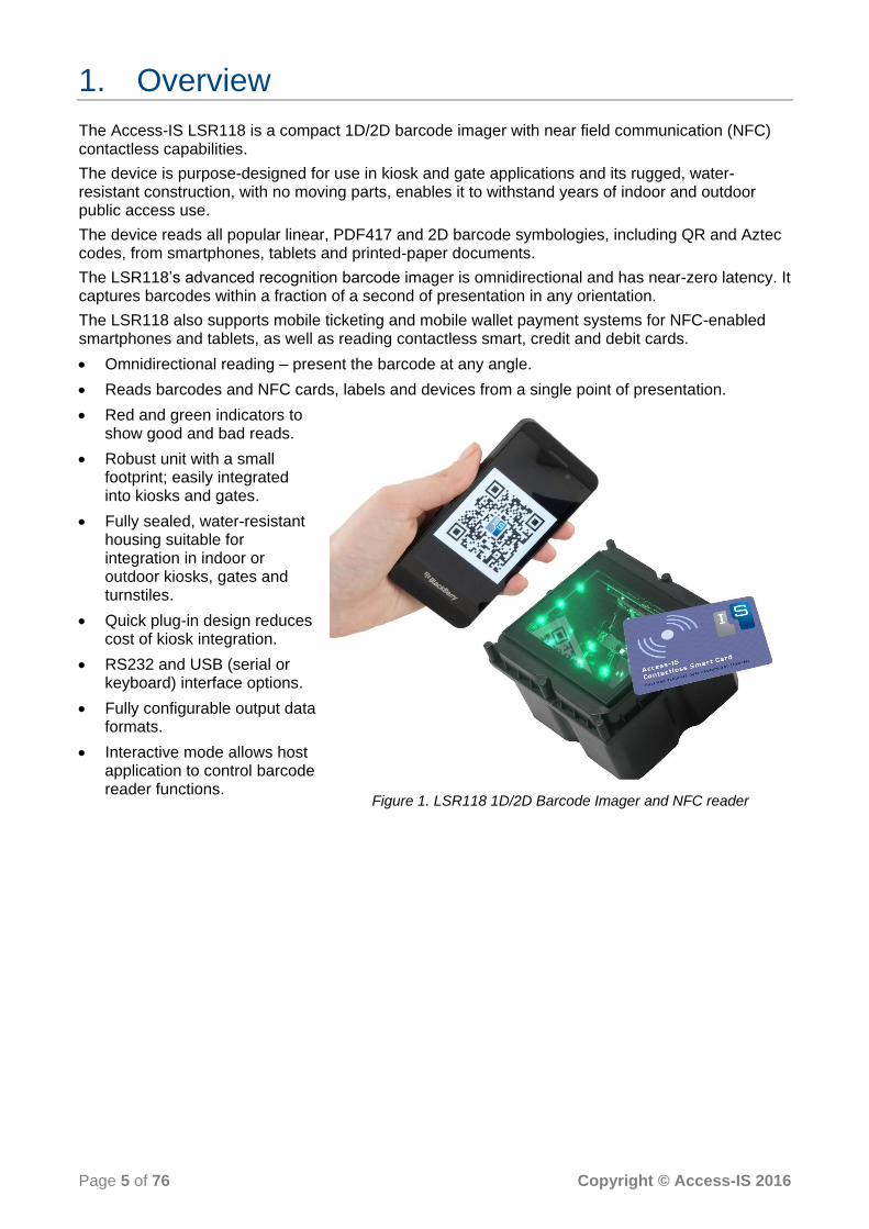
1. Overview
The Access-IS LSR118 is a compact 1D/2D barcode imager with near field communication (NFC) contactless capabilities.
The device is purpose-designed for use in kiosk and gate applications and its rugged, water-resistant construction, with no moving parts, enables it to withstand years of indoor and outdoor public access use.
The device reads all popular linear, PDF417 and 2D barcode symbologies, including QR and Aztec codes, from smartphones, tablets and printed-paper documents.
The LSR118’s advanced recognition barcode imager is omnidirectional and has near-zero latency. It captures barcodes within a fraction of a second of presentation in any orientation.
The LSR118 also supports mobile ticketing and mobile wallet payment systems for NFC-enabled smartphones and tablets, as well as reading contactless smart, credit and debit cards.
Omnidirectional reading – present the barcode at any angle.
Reads barcodes and NFC cards, labels and devices from a single point of presentation.
Red and green indicators to show good and bad reads.
Robust unit with a small footprint; easily integrated into kiosks and gates.
Fully sealed, water-resistant housing suitable for integration in indoor or outdoor kiosks, gates and turnstiles.
Quick plug-in design reduces cost of kiosk integration.
RS232 and USB (serial or keyboard) interface options.
Fully configurable output data formats.
Interactive mode allows host application to control barcode reader functions.
Figure 1. LSR118 1D/2D Barcode Imager and NFC reader

Page 6 of 76 Copyright © Access-IS 2016
2. Specifications
Specification Details
Dimensions (L x H x W) 109.8 mm x 67.4 mm x 105.9 mm
Weight 592 g (with cable)
Environmental Operating temperature: -25ºC to 50ºC Storage temperature: -30ºC to 70ºC Humidity: 95% RH, non-condensing IP67
Body Black ABS
Glass 4 mm Toughened White Soda Lime; BS EN60068-2-75 & IEC 62262:2002, rated to 3.5 J impact
Power requirements 5 V DC Requires USB power injector cable or independent power supply
Electrical interface Serial (RS232C) and 5 V USB
Barcode reading Reads barcodes from mobile phones, tablets and paper Linear: Code 2 of 5, Interleaved 2 of 5, EAN13, Code 3 of 9, Code 128 (plus others) 2D: PDF417, QR, Aztec, DataMatrix, (plus others)
NFC EMV: Certified to Level 1 Supported media: ISO14443 type A and B cards (Java cards); max baud 424K (extendable to 848K) MIFARE UL, Classic 1K, Classic 4K, UL-C, MIFARE Plus; max baud 106K
MTBF 85,000 hours
Approvals CE EMC Class B
EN 55022
EN 55024
CE Low Voltage Directive
EN 60950-1
IEC 60825-1 LED Safety Class 1
CE R&TTE Directive
ETSI EN 301 489
ETSI EN 302 291
FCC 47CFR Part 15 Subpart B Class A FCC 47CFR Part 15 Subpart C IEC 60825-1 LED Safety Class 1

Page 7 of 76 Copyright © Access-IS 2016
2.1 Part numbers
Product Part Number
Serial connected LSR118 AKEGEOSA941
USB power injector cable 5KBD133402
USB connected LSR118 AKEGEOSA902
Serial cable 5KBD387302
USB cable 5KBD386301
An external power supply is available, if required.
Please contact the Access-IS sales team: [email protected].
Page 8 of 76 Copyright © Access-IS 2016
3. Installation
3.1 Unpack the LSR118
Unpack the LSR118 and ensure that you have the following items:
Advisory notice card.
LSR118 device with attached serial cables or USB cable.
USB power injector cable or power supply (IEC cable not supplied).
Report any missing items or damage immediately to your Sales Representative.
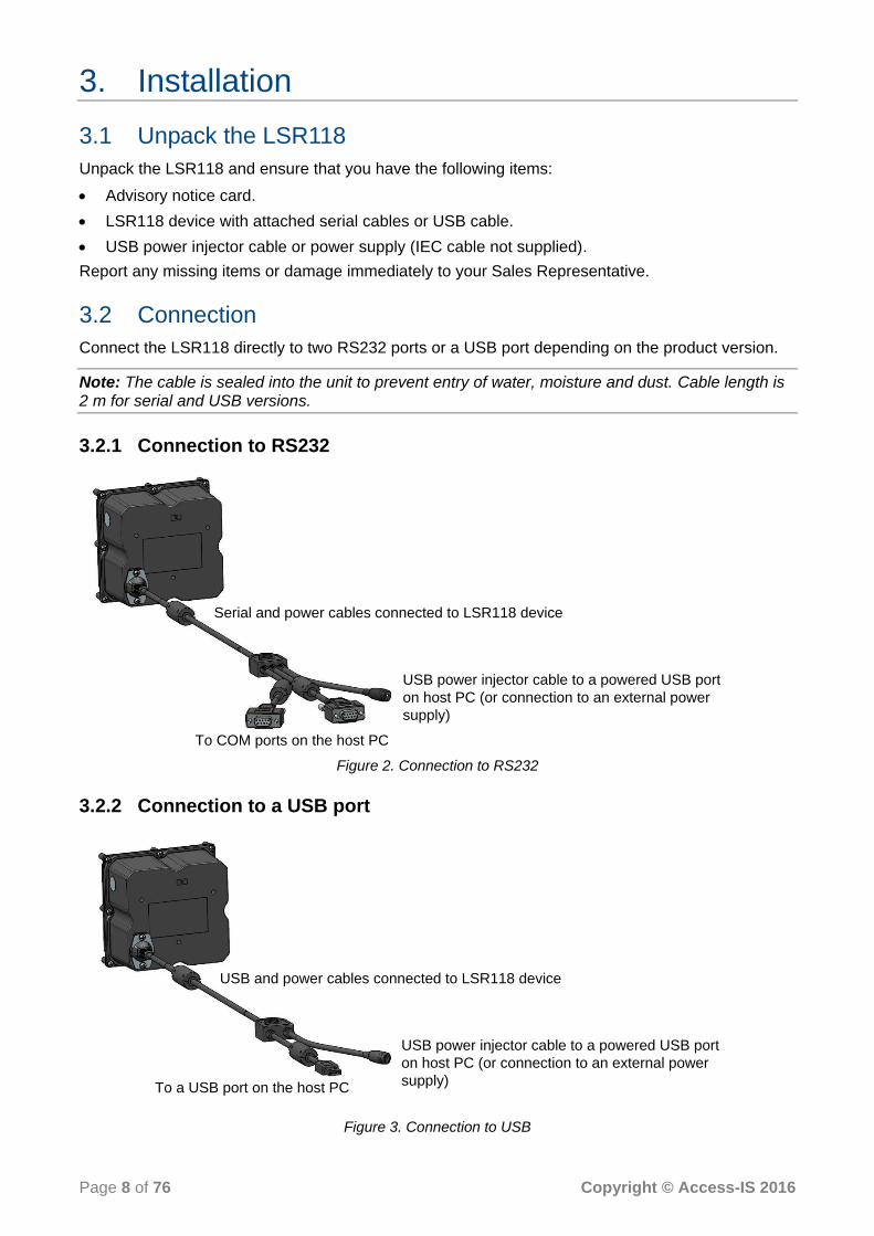
3.2 Connection
Connect the LSR118 directly to two RS232 ports or a USB port depending on the product version.
Note: The cable is sealed into the unit to prevent entry of water, moisture and dust. Cable length is 2 m for serial and USB versions.
3.2.1 Connection to RS232
Figure 2. Connection to RS232
3.2.2 Connection to a USB port
Figure 3. Connection to USB
Serial and power cables connected to LSR118 device
USB power injector cable to a powered USB port
on host PC (or connection to an external power
supply)
To COM ports on the host PC
To a USB port on the host PC
USB and power cables connected to LSR118 device
USB power injector cable to a powered USB port
on host PC (or connection to an external power
supply)

Page 9 of 76 Copyright © Access-IS 2016
3.3 Mounting
Mount the LSR118 into a kiosk, gate or similar device, if required. Refer to Figure 4 for the LSR118’s dimensions (in millimetres) and mounting points.
For optimum performance, do not position the LSR118 in direct sunlight.
NFC INSTALLATION WARNING
To optimise the performance, DO NOT install the LSR118 so that its NFC antenna is within 40 mm of a large metal or electrically conductive component or structure.
Failure to observe this instruction may lead to the product’s NFC performance deteriorating or even failing completely.
Figure 4. LSR118 dimensions and mounting points
Use three M3 screws (not provided) to mount the unit. Maximum insertion depth is 6 mm; minimum recommended insertion depth is 2 mm.
3.4 Barcode interface options
3.4.1 Serial connection
Connect a serial LSR118 device using an RS232 interface directly into a COM port. You must specify the baud rate, parity, data bits and stop bits.
Note: A serial LSR118 communicates directly with the COM port and does not require any additional drivers to be loaded.
3.4.2 USB connection
Connect a USB LSR118 device using one of three possible options. These options are compatible with all Linux and Windows operating systems from XP onwards.

Page 10 of 76 Copyright © Access-IS 2016
3.4.2.1 Keyboard interface
Virtual keyboard using Windows or Linux drivers
This option allows the device to operate without additional drivers, with the LSR118 emulating a keyboard. This is one-way communication; it is not possible to control the device directly in this mode. This mode will be slower than the other options as it adds an inter-character delay when typing the barcode data.
3.4.2.2 CDC interface
Virtual serial mode using the Windows CDC driver
This option assigns a COM port and the device communicates as a virtual serial device. Due to the nature of CDC serial port drivers, the COM port disappears if the unit is unplugged.
3.4.2.3 HID interface
Access-IS recommend the use of the HID interface for reliability. A HID interface recovers properly in the event of accidental disconnects or system power fluctuations; a CDC interface may not recover in these situations.
HID interface using the Access driver (Windows only)
The Access Serial Ports Service driver is fully configurable and outputs data in virtual serial or virtual keyboard. The output can be parsed and reformatted. The serial port is permanent and does not disappear if you unplug or hot swap the unit. This is one-way communication and the only command that you can send to the device is AIS_BO to enable or disable barcode reading. Refer
to page 26 for more information.
HID interface without the Access driver
This method is only suitable is you are familiar with HID programming.
It is possible to communicate directly with the LSR118 using the operating system’s built-in HID drivers. In this instance, HID reports, exactly 64 bytes in length, are sent between the host and the LSR118.
The implementation of this driver and the method of interaction will depend on the version of the host operating system. You should refer to the HID programming guide for the operating system you are using.
Refer to HID reports – barcode only on page 66 for the details of the HID reports used with the LSR118.
3.5 NFC interface options
3.5.1 Serial connection
Connect the NFC module using an RS232 interface directly into a COM port.
Note: A serial LSR118 communicates directly with the COM port and does not require any additional drivers to be loaded.
3.5.2 USB connection
The NFC module enumerates as a standard chip card interface device (CCID) smartcard reader. When you connect the device to the host, the NFC module uses the default Windows CCID drivers. It is not necessary to install custom drivers when running Windows XP and above.

Page 11 of 76 Copyright © Access-IS 2016
3.6 Barcode module installation (serial device)
A serial LSR118 communicates directly with the COM port and does not require any additional drivers to be loaded. Serial connectors are labelled: CONN1 = Barcode , CONN2 = NFC module.
1. Switch off the computer.
2. Connect the serial cables to COM ports on the computer and finger-tighten the two thumbscrews to secure the connectors to the port.
3. If using a USB power injector cable, plug the injector cable into the coaxial power connector on the splitter cable and then plug the USB connector into a powered USB port on the computer.
If using an Access-supplied power supply, plug the power cable into the coaxial power connector on the splitter cable and then connect the external power supply to an AC outlet.
4. Once the device is connected, switch on the computer.
3.7 Barcode module installation (USB device)
Note: If you intend to use the Access driver, ensure that you install the driver before you connect the LSR118 to the computer.
3.7.1 Driverless keyboard output
There is no additional driver required for this mode. Connect the USB cable from the LSR118 to a USB port on the computer.
3.7.2 CDC Windows driver
This method of USB installation uses the Windows CDC drivers.
For this method to operate, you must install the CDC drivers using the file, AccessISUSBCDC.inf,
which you can download from http://www.access-is.com/gettingstarted/.
The download (USB Driver for CDC Mode) includes full instructions for use.
Windows assigns a virtual COM port to the LSR118 device. You can find out the COM port number in Device Manager. You will require the port number to configure the LSR118.
3.7.3 Custom HID
3.7.3.1 HID interface using the Access serial driver (Windows only)
The recommended method for using a USB LSR118 is to configure the device to operate in HID mode. This allows the device to communicate with the Access driver.
For this method to operate, you must install first the Access driver (Access Serial Ports Service (ASPS)). Download ASPS from http://www.access-is.com/gettingstarted/.
The download (ASPS Software) includes full instructions for use.
Ensure that you install the driver before connecting the LSR118 to the host.
3.7.3.2 HID interface without the Access driver
There is no additional driver required for this mode. Connect the USB cable from the LSR118 to a USB port on the computer.
3.8 NFC module installation (serial device)
A serial LSR118 communicates directly with the COM port and does not require any additional drivers to be loaded. Serial connectors are labelled: CONN1 = Barcode , CONN2 = NFC module. Refer to Barcode module installation (serial device) on page 11 for installation instructions.

Page 12 of 76 Copyright © Access-IS 2016
3.9 NFC module installation (USB device)
When you connect a USB-connected LSR118 device to the host, Windows automatically detects the hardware and installs the standard CCID smartcard reader drivers. Some versions of Windows may prompt you to search automatically for a driver.
The NFC module also exposes a HID interface for configuration and control. Refer to NFC management interface commands on page 55 for the command set and its responses.
In Device Manager, the smartcard reader and HID-compliant device represent the NFC module. The barcode device appears under Ports (COM & LPT).
Figure 5. NFC module and barcode device in Device Manager (other device types not shown)
3.10 Test the device
Once you have connected the device and installed the relevant drivers, if applicable, you can test the device. To do this, wave a piece of paper in front of the glass; the reader’s LEDs should illuminate. If the device fails to respond when connected to the host, refer to the Troubleshooting section in this document.
3.11 Barcode configuration software
Connect to, and configure, the LSR118 using your own configuration tool, a terminal emulation program or the Access-IS configuration tool, which you can download from http://www.access-is.com/gettingstarted/.
Refer to the Barcode command reference on page 20 for details of the barcode commands, which you can use to configure the LSR118.
3.12 Communicate with the NFC module
Once the NFC module is enumerated, it registers itself with the Windows Smartcard Resource Manager. Since the NFC module is Personal Computer/Smart Card (PC/SC) compatible, you can use standard Windows smartcard functions to communicate with the module through the Windows Smartcard Resource Manager API. Refer to the Microsoft website for more detailed information on the Smartcard Resource Manager API.
For more information on the operation of the LSR118’s NFC reader, see page 30. Refer to page 38 for MIFARE media commands and responses and page 55 for NFC management interface commands.

Page 13 of 76 Copyright © Access-IS 2016
3.13 Troubleshooting
If the LSR118 does not appear to be working, refer to Table 1 to help identify and resolve the problem. For further assistance, contact [email protected].
Alternatively, use the Contact Customer Support Team page on the Access-IS website.
Note: Do not attempt to disassemble the LSR118 if it does not operate correctly.
Table 1. Troubleshoot the LSR118
Problem Solution
LSR118 not transmitting data to host Check that all cable connections between the LSR118 and host are secure. Ensure that the unit has power.
LSR118 cannot scan barcode Ensure that the unit is configured to read the barcode that you are scanning. If scanning a document, ensure that the print quality is good. If scanning a barcode on a mobile phone, ensure that you set the screen backlight on the phone to its brightest setting.
3.14 Maintenance
3.14.1 Cleaning
Clean the glass with a lint-free cloth. If the glass is dirty, wipe the glass with a lint-free cloth moistened with isopropyl alcohol or use an alcohol wipe. Do not use abrasive cleaners.
3.14.2 Storage
Store the unit in its original box, at a temperature of -30°C to 70°C.

Page 14 of 76 Copyright © Access-IS 2016
4. Barcode operating modes
The LSR118 operates in one of three ways, as defined by the AISOMD command. Refer to the
Barcode command reference on page 20 for a list of commands that you can send to configure the LSR118.
4.1 Mode summary
4.1.1 Dumb mode
The LSR118 is a one-way communication device.
The device detects the media and activates the imager and illumination. When the LSR118 reads the barcode, it sends the data to the host, activates the ‘Good Read’ indicators, and disables the imager and illumination. The imager and illumination do not reset until the LSR118 sensor fails to detect any media for 0.5 seconds.
4.1.2 Host mode
The LSR118 is a two-way communication device that reads barcodes and waits for a host to accept or reject the barcodes.
The device detects the media and activates the imager and illumination. When the device reads the barcode, it sends the data to the host and disables the imager and illumination. The LSR118 waits for a response from the host to accept or reject the data, which activates the ‘Good Read/Bad Read’ indicators on the device. The LSR118 waits for up to two seconds for an ‘Accept/Reject/Ignore’ command to activate indicators. The host sends an ‘Ignore’ command to reset the imager if no response from the indicators is required. The imager and illumination do not reset until the LSR118 sensor fails to detect any media for 0.5 seconds.
The ‘Ignore’ command requires version 1.0.21 (or later) of the firmware.
4.1.3 Interactive mode
Note: This is not the recommended mode for new installations.
The LSR118 is a two-way communication device, controlled fully by a host.
The LSR118 detects the media and sends a command to the host with this information. If the media is removed, a second command is sent telling the host that the media is no longer detected.
If the media is present, the host sends a command to activate the imager and illumination. When the LSR118 reads the barcode, it sends data to the host. The imager and illumination are not disabled. The LSR118 waits for a response from the host to accept or reject the data, which activates the ‘Good Read/Bad Read’ indicators and disables the imager and illumination. An ‘Ignore’ command may also be used, although untriggering the unit is more useful in most cases.
At any time, the host can send ‘Good Read’ or Bad Read’ commands activate or deactivate the imager and illumination.
Page 15 of 76 Copyright © Access-IS 2016
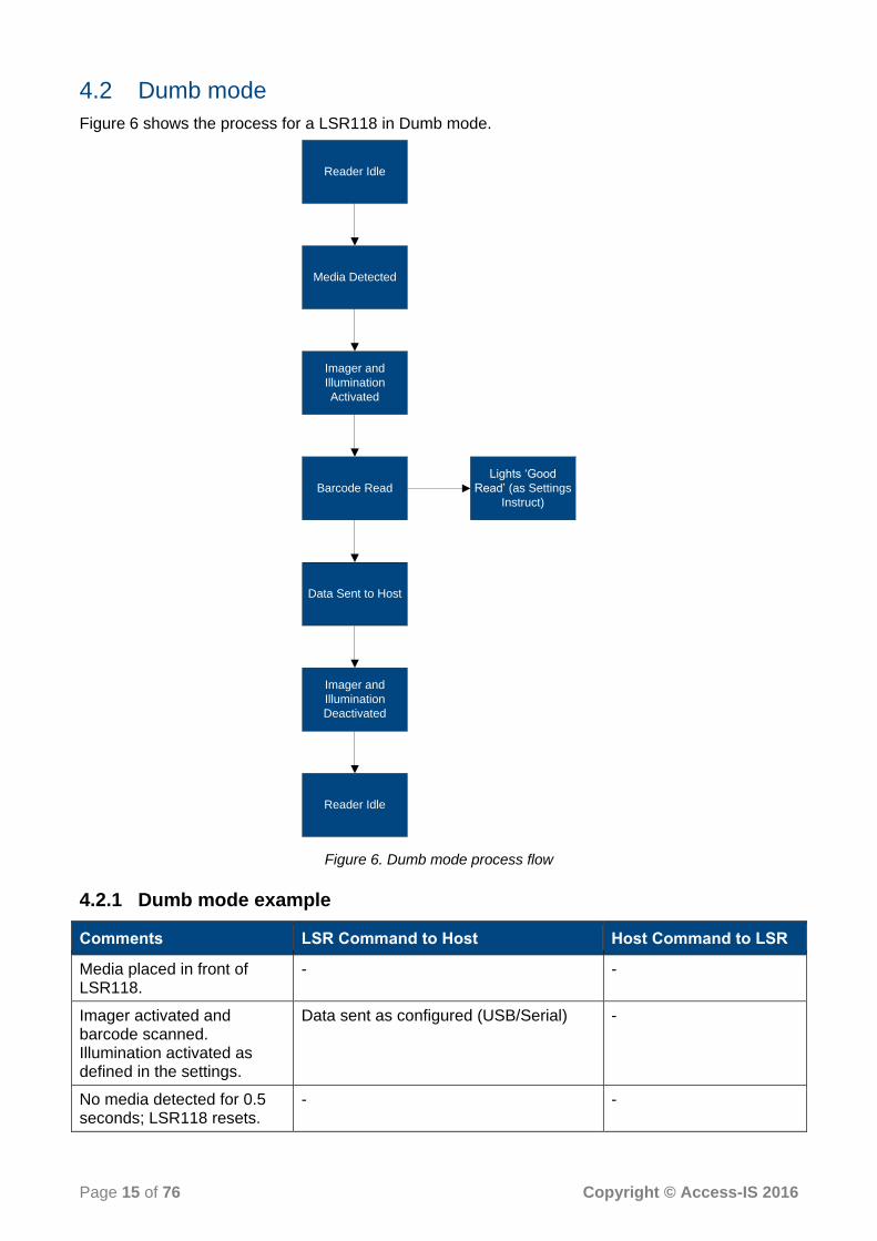
4.2 Dumb mode
Figure 6 shows the process for a LSR118 in Dumb mode.
Media Detected
Imager and
Illumination
Activated
Barcode Read
Data Sent to Host
Lights ‘Good
Read’ (as Settings
Instruct)
Reader Idle
Imager and
Illumination
Deactivated
Reader Idle
Figure 6. Dumb mode process flow
4.2.1 Dumb mode example
Comments LSR Command to Host Host Command to LSR
Media placed in front of LSR118.
- -
Imager activated and barcode scanned. Illumination activated as defined in the settings.
Data sent as configured (USB/Serial) -
No media detected for 0.5 seconds; LSR118 resets.
- -

Page 16 of 76 Copyright © Access-IS 2016
4.3 Host mode
Figure 7 shows the process for an LSR118 in Host mode.
Media Detected
Imager and
Illumination
Activated
Barcode Read
Data Sent to Host.
Imager and
Illumination
Deactivated
Accept or Reject?
Lights ‘Bad Read’
(as Settings
Instruct)
Lights ‘Good
Read’ (as Settings
Instruct)
Reject Accept
Reader Idle
Reader Idle
Ignore Command or
No Response within Timeout
Figure 7. Host mode process flow

Page 17 of 76 Copyright © Access-IS 2016
4.3.1 Host mode example
4.3.1.1 Accept
Comments LSR Command to Host Host Command to LSR
Media placed in front of LSR118.
- -
Imager activated and barcode scanned. Illumination activated as defined in the settings.
Data sent as configured (USB/Serial) -
Host decides to accept or reject the data.
- ‘Good Read’: AISXXR0
Lights activated as defined in the ‘Good Read’ settings.
- -
No media detected for 0.5 seconds; LSR118 resets.
- -
4.3.1.2 Reject
Comments LSR Command to Host Host Command to LSR
Media placed in front of LSR118.
- -
Imager activated and barcode scanned. Illumination activated as defined in the settings.
Data sent as configured (USB/Serial) -
Host decides to accept or reject the data.
- ‘Bad Read’: AISXXR1
Lights activated as defined in the ‘Bad Read’ settings.
- -
No media detected for 0.5 seconds; LSR118 resets.
- -
4.3.1.3 Ignore
Comments LSR Command to Host Host Command to LSR
Media placed in front of LTR118.
- -
Imager activated and barcode scanned. Illumination activated as defined in the settings.
Data sent as configured (USB/Serial) -
Host decides to accept or reject the data.
- ‘Ignore and Continue’: AISXXR2
No media detected for 0.5 seconds; LTR118 resets.
- -

Page 18 of 76 Copyright © Access-IS 2016
4.4 Interactive mode
Figure 8 shows the process for an LSR118 in Interactive mode. The host can send ‘Good Read’ and ‘Bad Read’ commands to the LSR118 at any time.
Media Detected,
Message Sent
Requesting
Trigger
Send Trigger?
Imager and
Illumination
Activated
Trigger
Barcode Read
Data Sent to Host
Accept or
Reject?
Lights ‘Bad Read’
(as Settings
Instruct)
Lights ‘Good
Read’ (as Settings
Instruct)
Imager and
Illumination
Deactivated
Reject Accept
Reader Idle
Untrigger
Force Trigger
Reader Idle
Force Untrigger
Ignore Command
Figure 8. Interactive mode process flow

Page 19 of 76 Copyright © Access-IS 2016
4.4.1 Interactive mode example
4.4.1.1 ‘Good Read’ initiated by LSR detecting media
Comments LSR Command to Host Host Command to LSR
Media placed in front of LSR118. LSR118 sends commands to host notifying of media.
[0x16][0x0D]TRIG:1[0x16][0x0A] -
Host sends a command to trigger the imager.
- [0x16][0x74][0x0D]
Imager activated and barcode scanned. Illumination activated as defined in the settings.
Data sent as configured (USB/Serial) -
Host decides to accept or reject the data.
- ‘Good Read’: AISXXR0
Lights activated as defined in the ‘Good Read’ settings.
- -
No media detected for 0.5 seconds; LSR118 resets.
- -
4.4.1.2 ‘Good Read’ initiated by host sending trigger command
Comments LSR Command to Host Host Command to LSR
Host sends a command to trigger the imager. This could be due to a second sensor.
- [0x16][0x74][0x0D]
Imager activated, it remains activated until untriggered or a ‘Good Read/Bad Read’ command is received. Lights activated as defined in the settings.
- -
Data read by imager. Data sent as configured (USB/Serial) -
Host decides to accept or reject the data.
- ‘Good Read’: AISXXR0
Lights activated as defined in the ‘Good Read’ settings.
- -
No media detected for 0.5 seconds; LSR118 resets.
- -
Page 20 of 76 Copyright © Access-IS 2016
5. Barcode command reference
Commands are sent with a prefix of [0x16][0x4D][0x0D] causing the command sequence to
take the form [0x16][0x4D][0x0D]<Menu Command>. The menu commands are six characters
long with a parameter (if required).
To send a command to modify a configuration parameter
Send the six character command concluded by a dot ‘.’ or an exclamation mark ‘!’. The dot stores the setting permanently and the exclamation mark keeps it temporarily until power is removed from the device.
For example, [0x16][0x4D][0x0D]AISKBL1. sets the keyboard localisation to United States
when the device is operating as a USB keyboard.
To query the current settings (including a temporary one)
Send the six character command with a ‘?’ instead of the parameter and the LSR118 will return the command with the current setting.
For example, [0x16][0x4D][0x0D] AISINF? queries the device interface and returns the
current value.
To query the stored value
Send the six character command with a ’^’ instead of the parameter and the LSR118 will return the command with the stored setting.
For example, [0x16][0x4D][0x0D] AISINF^ returns the current illumination mode.
To list parameter options
Send the six character command with a ‘*’ instead of the parameter and the LSR118 will return the command with the parameter options.

Page 21 of 76 Copyright © Access-IS 2016
5.1 Basic configuration
These commands set the device interface, connection parameters and specify the operating mode.
Table 2. Basic configuration commands
Command Description Default Parameters/Range
AISINF Selects the device interface. When a Serial cable is used, the configuration is overruled and AISINF0
is used. When a USB cable is used, the configuration AISINF0 is overruled and
AISINF1 is used.
0 0 - Serial 1 - USB serial (CDC) 2 - USB keyboard 3 - HID POS
AISBAU Sets the baud rate for a Serial connection. Only used when AISINF is set to 0
(Serial).
9 0 - 300 bps 1 - 600 bps 2 - 1200 bps 3 - 2400 bps 4 - 4800 bps 5 - 9600 bps 6 - 19200 bps 7 - 38400 bps 8 - 57600 bps 9 - 115200 bps
AISSCP Sets the connection parameters for a Serial connection. Only used when AISINF is set to 0
(Serial).
2 0 - 7N1 1 - 7N2 2 - 8N1 3 - 7E1 4 - 7E2 5 - 8E1 6 - 7O1 7 - 7O2 8 - 8O1
AISKBL Keyboard localization; this defines the Windows keyboard mapping for correct output of characters. Only used when AISINF is set to 2 (USB
keyboard).
0 0 - US (United States) 1 - UK (United Kingdom) 2 - IT (Italy) 3 - ES (Spain) 4 - DE (Germany) 5 - CH (Switzerland) 6 - CZ (Czech Republic) 7 - FR (France) 8 - BE (Belgium) 9 - SE (Sweden)
AISCHR Sets the inter-character delay (in milliseconds). Only used when AISINF is set to 2 (USB
keyboard).
2 0–250 milliseconds
AISOMD Indicator mode setting. 0 0 - Dumb mode 1 - Host mode 2 - Interactive mode
AISTAM Triggers Auto mode. Only used when AISOMD is set to 2
(Interactive).
0 0 - Normal operation 1 - Automatic untrigger when media removed

Page 22 of 76 Copyright © Access-IS 2016
Command Description Default Parameters/Range
DLYGRD Sets the delay between successful reading of one barcode and the reading of another barcode. Each unit is equivalent to 1 millisecond.
2000 0–25000
5.2 Prefix and suffix solutions
These commands allow you to add a prefix and/or suffix to all barcodes.
Note: If you send more than one prefix or suffix to the device, they will stack in chronological order. You must send a clear command if you want to use a single prefix or suffix.
Table 3. Prefix and suffix commands
Command Description Default Parameters/Range
PREBK299xx Adds a prefix to all barcode symbologies. Any two-character hex ASCII code can replace xx. For example, to add STX (Start of Text) as a prefix, use the command PREBK29902.
You can add more than one prefix, as required.
- xx - Hex value
PRECA2 Clears all prefixes. - -
SUFBK299xx Adds a suffix to all barcode symbologies. Any two-character hex ASCII code can replace xx. You can add more than one suffix, as required. For example, to add CR (Carriage Return) and ETX (End of Text) as a suffix, use the command SUFBK2990D03.
- xx - Hex value
SUFCA2 Clears all suffixes. - -

Page 23 of 76 Copyright © Access-IS 2016
5.3 LSR118 illumination
The standard method of reading barcodes cycles the illumination on and off. You can control illumination for various different applications using the commands in Table 4. For example, it is often beneficial to turn off the illumination to prevent reflections from shiny surfaces, for example, mobile phones.
Table 4. Illumination commands
Command Description Default Parameters/Range
AISILL Adaptive illumination mode (see page 24).
2 0 - Off (Phone only) 1 - Off (Paper only) 2 - On (Paper optimised) 3 - On (Phone optimised)
AISONT Illumination on time. Applies to AISILL modes 2 and 3 only
(adaptive illumination on). Each unit is equivalent to 100 milliseconds.
8 0–200
AISOFT Illumination off time. Applies to AISILL modes 2 and 3 only
(adaptive illumination on). Each unit is equivalent to 100 milliseconds.
8 0–200
AISONM Illumination on mode. When set to 0, the timing for the illumination on period is set to a single value, AISONT.
When set to 1, the illumination on period cycles continuously (while triggered) through the three AISONx values.
0 0 - Normal adaptive operation; uses AISONT
timing 1 - Cycles through AISON1
to AISON3 timings
AISON1 Illumination on time 1. Applies to AISILL modes 2 and 3 only
(adaptive illumination on). Each unit is equivalent to 100 milliseconds.
1 0–200
AISON2 Illumination on time 2. Applies to AISILL modes 2 and 3 only
(adaptive illumination on). Each unit is equivalent to 100 milliseconds.
2 0–200
AISON3 Illumination on time 3. Applies to AISILL modes 2 and 3 only
(adaptive illumination on). Each unit is equivalent to 100 milliseconds.
5 0–200
AISOFM Illumination off mode. When set to 0, the timing for the illumination off period is set to a single value, AISOFT.
When set to 1, the illumination off period cycles continuously (while triggered) through the three AISOFx values.
0 0 - Normal adaptive operation; uses AISOFT
timing 1 - Cycles through AISOF1
to AISOF3 timings

Page 24 of 76 Copyright © Access-IS 2016
Command Description Default Parameters/Range
AISOF1 Illumination off time 1. Applies to AISILL modes 2 and 3 only
(adaptive illumination on). Each unit is equivalent to 100 milliseconds.
1 0–200
AISOF2 Illumination off time 2. Applies to AISILL modes 2 and 3 only
(adaptive illumination on). Each unit is equivalent to 100 milliseconds.
2 0–200
AISOF3 Illumination off time 3. Applies to AISILL modes 2 and 3 only
(adaptive illumination on). Each unit is equivalent to 100 milliseconds.
5 0–200
5.3.1 Adaptive illumination modes
The illumination modes allow you to configure the device to provide the best lighting to read barcodes on different types of media.
0 - Off (Phone only)
Adaptive illumination is off. The illumination LEDs do not light when you present media to the device.
1 - Off (Paper only)
Adaptive illumination is off. The illumination LEDs light when you present media to the device. The LEDs illuminate until the device reads the barcode or you remove the media.
2 - On (Paper optimised)
Adaptive illumination is on. The illumination LEDs switch ‘On’ and ‘Off’ continuously when you present media to the device. The LEDs cycle ‘On’ and ‘Off’ until the device reads the barcode or you remove the media. Use the illumination commands in Table 4 to set the ‘On’ and ‘Off’ time.
3 - On (Phone optimised)
Adaptive illumination is on. The illumination LEDs switch ‘Off’ and ‘On’ continuously when you present media to the device. The LEDs cycle ‘Off’ and ‘On’ until the device reads the barcode or you remove the media. Use the illumination commands in Table 4 to set the ‘Off’ and ‘On’ time.

Page 25 of 76 Copyright © Access-IS 2016
5.4 Indicator control
These commands control the behaviour of the ‘Good Read’ and ‘Bad Read’ LEDs.
Note: There are no lid lights on the LSR118; these are replaced by the NFC antenna.
Table 5. Indicator LED commands
Command Description Default Parameters/Range
AISGDT ‘Good Read’ LED indicator duration. Each unit is equivalent to 100 milliseconds.
5 0–200
AISGDS ‘Good Read’ duration start. Specifies when the ‘Good Read’ indicator illuminates.
0 0 - At ‘Good Read’ 1 - At media removal
AISGIN ‘Good Read’ indication stop. Specifies when the ‘Good Read’ indicator extinguishes.
1 0 - At media removal 1 - Continues after media removal
AISBDT ‘Bad Read’ LED indicator duration. Each unit is equivalent to 100 milliseconds.
8 0–200
AISBDS ‘Bad Read’ duration start. Specifies when the ‘Bad Read’ indicator illuminates.
0 0 - At ‘Bad Read’ 1 - At media removal
AISBIN ‘Bad Read’ indication stop. Specifies when the ‘Bad Read’ indicator extinguishes.
1 0 - At media removal 1 - Continues after media removal
AISGSL Switches between LED locations for the ‘Good Read’ indicator.
5 0 - No lights 1 - Board green lights 2 - Board red lights
AISBSL Switches between LED locations for the ‘Bad Read’ indicator.
10 0 - No lights 1 - Board green lights 2 - Board red lights

Page 26 of 76 Copyright © Access-IS 2016
5.5 Development commands
5.5.1 Firmware and imager levels
The firmware levels identify the release and build of a unit. Send the command AISFWV? to obtain
this information. For example: SB 01.00.00 is a first generation LSR118.
To check the latest firmware version or to update firmware, contact [email protected].
Table 6. Firmware and imager commands
Command Description Default Parameters/Range
AISXXR Simulates read outcome. Used in Interactive mode to communicate to the user after the host has checked the data. Only applicable to Interactive mode and Host mode.
- 0 - Good Read 1 - Bad Read 2 - Ignore (requires version 1.0.21 of the barcode module firmware)
AISIOP Interactive mode option flag. Only applicable to Interactive mode (AISOMD2).
If this flag is set, then the TRIG messages from the LSR118 are sent only on media detect and media removed, regardless of commands from the host.
0 0 - Disabled 1 - Enabled
AISRDS Changes the configuration back to its default values.
Warning: This command resets all parameters to their default values,
including any values specific to your stored configuration.
- 1
AISFWV Returns the version of the firmware. - -
AIS_WA Returns the firmware version of the imager.
- -
AIS_TD Returns the timestamp of the firmware release.
1 -
AIS_BO Enables or disables barcode reading. This command is stored in volatile memory so will return to the default setting on power cycle.
1 0 - Off 1 - On
AISDLE Include DLEs (Data Link Escape). 0 0 - Off 1 - On
AISNRD Sets a ‘No Read’ message, sent at defined intervals.
0 0 - Off 1–60000 milliseconds
232CRD CTS is raised when a ‘Good Read’ output is received.
0 0 - Off 1 - On
232CTS Hardware handshaking - requires the CTS to be high.
0 0 - Off 1 - On

Page 27 of 76 Copyright © Access-IS 2016
5.5.2 Status LED
The LSR118 contains two small orange LEDs on the main circuit board, typically used for debug purposes only. We recommend turning these off in normal use.
A typical configuration will have these turned off, but the default values will be as below (for example, when using the AISRDS command).
Note: You can combine more than one function by adding the function numbers together. For example, Brownout status and Intelli sensor reset is 48 + 64 = 112.
Table 7. Status LED commands
Command Description Default Parameters/Range
AISLS1 Status LED function. 4 0 - None 1 - Power on 2 - Loader 3 - Power on and loader 4 - Power on except when triggered 16 - Brownout detection (Diagnostic) 32 - Brownout reset (Diagnostic) 48 - Brownout status - Detection or reset (Diagnostic) 64 - Intelli sensor reset (Diagnostic) 128 - Watchdog reset (Diagnostic)
AISLS2 Status LED function. 2 0 - None 1 - Power on 2 - Loader 3 - Power on and loader 4 - Power on except when triggered 16 - Brownout detection (Diagnostic) 32 - Brownout reset (Diagnostic) 48 - Brownout status - Detection or reset (Diagnostic) 64 - Intelli sensor reset (Diagnostic) 128 - Watchdog reset (Diagnostic)

Page 28 of 76 Copyright © Access-IS 2016
5.6 Triggering
These commands control triggering and untriggering of the LSR118.
Table 8. Triggering commands
Command Description Default Parameters/Range
AISTUT Automatically untrigger. 0 0–25000 milliseconds
AISTMD Convert trigger modes. Warning: This is for advanced users only and modification may
cause the device to become inoperable.
1 0 - Imager must be triggered 1 - Imager in presentation mode
AISTST Soft trigger timeout. Specifies how long the LSR118 retains barcode information before discarding. Only used with AISOMD1 or AISOMD2.
2000 1000–25000 milliseconds
AISTPT Presentation trigger timeout. Specifies how long the imager will wait before reading a new barcode.
2000 1000–30000 milliseconds
SNSSMO Sensor maximum on time. Set to 0 to disable this feature. Each unit is equivalent to 100 milliseconds (600 = 60 seconds). If the infrared sensor detects media for more than the timeout (for example, because there is a sticker on the glass), it is disabled allowing the imager to work in presentation mode.
600 0–60000
5.6.1 Interactive mode
The commands to trigger the LSR118 for Interactive mode do not follow the same format as described in Table 8. For Interactive mode, trigger commands are sent as [0x16][0x74][0x0D]
and [0x16][0x75][0x0D] (see Table 9) instead of the [0x16][0x4D][0x0D] command.
Table 9. Triggering commands in Interactive mode
Command Description Default Parameters/Range
[0x16][0x74][0x0D] Triggers the LSR118. - -
[0x16][0x75][0x0D] Untriggers the LSR118. This cannot be done when media is detected by the LSR118.
- -
Page 29 of 76 Copyright © Access-IS 2016
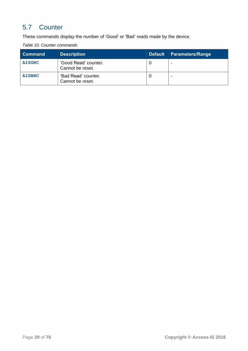
5.7 Counter
These commands display the number of ‘Good’ or ‘Bad’ reads made by the device.
Table 10. Counter commands
Command Description Default Parameters/Range
AISGRC ‘Good Read’ counter. Cannot be reset.
0 -
AISBRC ‘Bad Read’ counter. Cannot be reset.
0 -

Page 30 of 76 Copyright © Access-IS 2016
6. NFC operation
Near Field Communication (NFC) is a standard form of communication between an NFC reader and NFC supported media like smartcards, tags and smart phones.
NFC is a short-range wireless technology, which allows two devices to exchange securely small amounts of data over a distance of a few centimetres.
The adoption of NFC technology by mobile devices and passports has seen NFC technology gain in popularity. Consumers can now perform contactless transactions with a single touch, and use NFC devices for public transport, ticketing and access control.
The LSR118 operates in NFC reader mode and processes NFC (and barcode) data from a single point of presentation in any orientation.
The NFC module in the LSR118 is Personal Computer/Smart Card (PC/SC) compatible and you can use standard Windows smartcard functions to communicate with the module through the Windows Smartcard Resource Manager API.
6.1 Summary of operation
An NFC reader reads/writes blocks from/to a microprocessor or MIFARE card. When NFC media connects to the LSR118’s NFC reader, the device retrieves an Answer to Reset (ATR) from the card.
The ATR specifies certain communication parameters, including the card’s nature and state.
If the ATR identifies a microprocessor card, the host application sends Application Protocol Data Unit (APDU) commands to the card using the Windows Smartcard API.
The format of the command and response APDUs depend on the type of media.
If the media type is a MIFARE card, the NFC module constructs an ATR from the fixed elements that identify the card. See page 32 for more information.
Once the application detects a MIFARE-type card, it can then use MIFARE commands to communicate with it (see page 38).
The host sends APDU or MIFARE commands to the card over the PC/SC interface using the SCardTransmit function in the Windows Smartcard API and gets data back from the card.
Once communication is complete, or a user removes the card, the NFC module disconnects from the card and waits for another card connection.
Figure 9 shows an overview of the process that the NFC module in the LSR118 uses to identify and communicate with contactless media.

Page 31 of 76 Copyright © Access-IS 2016
Figure 9.NFC module-contactless media process flow

Page 32 of 76 Copyright © Access-IS 2016
6.2 Serial communication
6.2.1 Communication parameters
The NFC module in a serial-connected LSR118 uses the following default serial communication settings. Change the serial device baud rate using the Set serial interface baud rate command (on page 65).
Table 11. Serial communication default parameters
Parameter Value
Baud rate 115200
Data format 8 bits
Parity None
Stop bits 1
Flow control RTS/CTS
6.2.2 Communicating with individual readers
The individual readers inside the NFC module are identified by unique slot IDs. All CCID packets should have a CCID header, which has a byte field called bSlot. This field specifies the slot ID of
the reader with which the application wishes to communicate.
The slot ID value uniquely identifies the reader (within NFC module) to which the CCID packet is sent, and identifies the reader which is sending the response back to the application.
Table 12 shows the Slot ID values and their mapping to the readers.
Table 12. Slot ID and reader mappings
Slot ID value Reader
0 NFC
1 Smartcard #0 (SMC0)
2 Smartcard #1 (SMC1)
3 Smartcard #2 (SMC2)
4 Smartcard #3 (SMC3)
[0xFF] Management
The Management Interface is used to set the operating and debug parameters of the NFC module.
Note: Do not send commands to a reader that is not enabled.
6.2.3 Communication format
The data is sent to and from the NFC module in 64-byte chunks. Figure 10 shows how the NFC module transfers a 256-byte CCID packet.

Page 33 of 76 Copyright © Access-IS 2016
CCID Packet (256 bytes)
1st 64 byte chunk 2nd 64 byte chunk 3rd 64 byte chunk 4th 64 byte chunk
At least 2 character
idle time (~200µs)
At least 3 ms idle time for EOP
Figure 10. Example data transfer of a 256-byte data packet
The entire CCID packet including the header is broken down into 64-byte packets, which are transmitted one at a time. Ensure that there is at least a two-character idle time (approximately 200 microseconds) between consecutive 64-byte chunks. This idle time gives an opportunity for the serial device to save and clear its receiving buffer. The last data packet can be less than 64 bytes long. End-of-packet (EOP) is indicated by at least three milliseconds of idle time.
When EOP is received by the module, it internally checks the CCID packet’s length indicated in the CCID packet header.
If the CCID packet header’s length is equal to (or less than) the received CCID packet length, then the module processes that packet.
If the CCID packet header’s length is more than the received CCID packet size length, then the module waits for the next 64-byte chunk to arrive.
Note: When a CCID packet transmission starts, the first 64-byte chunk includes the CCID header, which indicates the slot ID where the data is being sent to or received from.
Each command message sent to a particular reader receives an appropriate response from the NFC module. The serial host does not send another command message to a reader until it receives a response. However, the serial host may send command messages concurrently to different readers at the same time. The NFC module may not respond in the same sequence as the sent commands. The response depends on the internal priority of the readers and the time taken to process the request by the media.
6.3 Notifications and data exchanges (serial connection)
6.3.1 Media arrival and removal notification
The NFC reader sends out three bytes to notify media arrival or removal. The format of these three bytes is shown in Table 13.
Table 13. Media arrival or removal
1st Byte 2nd Byte 3rd Byte
Always [0x50] Slot / media status Media type
Slot / media status
The first most significant 4 bits denote the reader slot ID. The least 4 bits denote the media status. If media status is 0 then the media is not present. If it is 1, then the media is present.

Page 34 of 76 Copyright © Access-IS 2016
Media type
The value of the media type byte indicates the media type.
Table 14. Media type byte values
Media type value Type Current support
No Media present [0x00] Yes
ISO14443-4 A [0x01] Yes
ISO14443-4 B [0x02] Yes
Mifare Classic 1K [0x03] Yes
Mifare Classic 4K [0x04] Yes
Mifare Ultralight [0x05] Yes
Mifare Plus [0x06] Yes
Felica media [0x07] No
ISO15693 [0x08] No
NFC Type 1 Tag [0x09] No
NFC DEP media [0x0A] No
The notifications can be disabled if not required using the Disable media arrival and removal notifications command (on page 64).
6.3.2 Media data exchange
To exchanged data with the media, the serial host constructs the data with a CCID header. The CCID header should have a valid slot ID where the data is received. Table 15 summarises the supported CCID exchanges.
Table 15. Supported CCID exchanges
Message name Command bMessageType
Response message Response bMessageType
PC_to_RDR_IccPowerOn [0x62] RDR_to_PC_DataBlock [0x80]
PC_to_RDR_IccPowerOff [0x63] RDR_to_PC_SlotStatus [0x81]
PC_to_RDR_GetSlotStatus [0x65] RDR_to_PC_SlotStatus [0x81]
PC_to_RDR_XfrBlock [0x6F] RDR_to_PC_DataBlock [0x80]
PC_to_RDR_GetParameters [0x6C] RDR_to_PC_Parameters [0x82]
PC_to_RDR_ResetParameters [0x6D] RDR_to_PC_Parameters [0x82]
PC_to_RDR_SetParameters [0x61] RDR_to_PC_Parameters [0x82]
To exchange data with the media, PC_to_RDR_XfrBlock message should be used.

Page 35 of 76 Copyright © Access-IS 2016
6.3.3 Get the ATR of the media
Once media has been detected, the ATR of the media can be retrieved by sending the message, PC_to_RDR_IccPowerOn. This message is sent from the serial host as shown in Table 16.
Table 16. PC_to_RDR_IccPowerOn message format
Field Offset Size in bytes Value/Description
bMessageType 0 1 [0x62]
dwLength 1 4 0 (Little endian format)
bSlot 5 1 Destination reader slot ID. Please refer to Communication parameters on page 32.
bSeq 6 1 0
bPowerSelect 7 1 0
abRFU 8 2 0
The NFC module respond with a RDR_to_PC_DataBlock message conveying the ATR of the
media it has found. If there is an error, then appropriate error message will be conveyed back in bStatus and bError fields and ATR may not be present in abData field.
Field Offset Size in bytes Value/Description
bMessageType 0 1 [0x80]
dwLength 1 4 Size of abData field (Contains the ATR, if
present)
bSlot 5 1 Source Reader slot ID. Please refer to Communication parameters on page 32.
bSeq 6 1 Same as command message
bStatus 7 1 0
bError 8 1 0
bChainParameter 9 1 0
abData 10 Size of the ATR ATR of the media, if present
6.3.4 Communicate with the media
To communicate with the media, PC_to_RDR_XfrBlock message is sent from the serial host as
shown in Table 17.
Table 17.PC_to_RDR_XfrBlock message
Field Offset Size in bytes Value/Description
bMessageType 0 1 [0x6F]
dwLength 1 4 Size of abData field in little endian format
bSlot 5 1 Destination Reader slot ID. Please refer to Communication parameters on page 32.
bSeq 6 1 0
bBWI 7 1 0
wLevelParameter 8 2 0

Page 36 of 76 Copyright © Access-IS 2016
Field Offset Size in bytes Value/Description
abData 10 Size of the data to be sent to the media
Contains the data to be sent to the media
The NFC module sends out the data in the abData field to the media. The media processes the
data and replies with an appropriate response. The NFC module receives the media response and communicates back to the serial host by sending a RDR_to_PC_DataBlock message as in
Table 17.
Table 18. RDR_to_PC_DataBlock message
Field Offset Size in bytes Value/Description
bMessageType 0 1 [0x80]
dwLength 1 4 Size of abData field in little endian
bSlot 5 1 Source Reader slot ID. Please refer to Communication parameters on page 32.
bSeq 6 1 Same as command message
bStatus 7 1 0
bError 8 1 0
bChainParameter 9 1 0
abData 10 Size of the media response
Media response, if present
If PC_to_RDR_XfrBlock message is sent when a media is not present, the reader responds with
bStatus and bError fields set to [0x42] and [0xFE] respectively. The field dwLength is also
set to 0 and no abData field is present.
6.4 MIFARE cards
When the reader detects NFC media, the application gets the ATR of the media. Since there is no ATR present for MIFARE media, the NFC module constructs an ATR from the fixed elements that identify the card.
The ATR for MIFARE media is 20 bytes long. It has fixed values, with the exception of the 15th byte, which indicates the type of MIFARE media. Table 19 shows the ATRs for different types of MIFARE media.
Table 19. MIFARE media ATR bytes
MIFARE media type ATR bytes
1K Classic 3B 8F 80 01 80 4F 0C A0 00 00 03 06 03 00 03 00 00 00 00 68
4K Classic 3B 8F 80 01 80 4F 0C A0 00 00 03 06 03 00 04 00 00 00 00 6F
Ultralight 3B 8F 80 01 80 4F 0C A0 00 00 03 06 03 00 05 00 00 00 00 6E
Note that the value of the 15th byte indicates the type of MIFARE media.
The application software can look for these specific ATR bytes to detect MIFARE-type media. Once it detects a MIFARE-type medium, the application can then use the MIFARE commands to communicate with it.
Refer to MIFARE media commands and responses on page 38 for details of the MIFARE media commands and responses that you can use.

Page 37 of 76 Copyright © Access-IS 2016
6.5 Contactless microprocessor smartcards
The NFC module detects contactless microprocessor smartcards such as Java cards, ACOS, Desfire, SmartMX cards and most e-Passports. These media have an Answer to Reset (ATR), which the NFC module retrieves. The host application can send Application Protocol Data Unit (APDU) commands to these media using the Windows Smartcard API.
Note: The format of the command and response APDUs depend on the type of media. Refer to the media’s user manual for the command and response formats.

Page 38 of 76 Copyright © Access-IS 2016
7. MIFARE media commands and responses
This section describes the MIFARE media commands and responses for the NFC module.
In serial mode, all MIFARE commands use a CCID PC_to_RDR_XferBlock message to
communicate with the module/card. The application software should be aware of this and it should add/remove the CCID header from the command/responses.
Note: All of the MIFARE commands for a serial device have an attached CCID header, which is shown in black text in the examples. The header is always 10 bytes in length; the second byte indicates the length of the command or response. The example commands and responses omit trailing zeroes.
The command bytes have a command code, which is bit encoded as follows:
Bit
7 6 5 4 3 2 1 0
1 - RF selection prior to command operation
1 - Authentication after RF selection (if enabled) but before the command operation
Command function code
0 - No RF selection 0 - No authentication *
* Some commands will automatically perform authentication if you enable RF selection.
When you enable RF selection, the reader resets each time it polls.
When you disable RF selection, the reader polls using the Universally Unique Identifier (UUID) that it had last time it polled; the reader looks for the same card.
Note: The MIFARE command code has two possible values depending on whether the command includes authentication (bit 6). For example, RF select and no authentication: binary = 10000000,
hex = [0x80], RF select with authentication: binary = 11000000, hex = [0xC0]. Authentication
may or may not apply depending on the command.
7.1 MIFARE get media type
Use this command to return the MIFARE media type.
7.1.1 MIFARE command bytes
MIFARE command bytes
Command header Command code
[0x00] [0x00] or [0x40]
Get type
[0x80] or [0xC0]
RF select and get type (No authentication performed)

Page 39 of 76 Copyright © Access-IS 2016
7.1.2 MIFARE response bytes
MIFARE response bytes
Response header Response code(1) MIFARE type (2) Media UID (2) Status bytes
[0x00] Any one of the following values [0x01]
[0x41]
[0x81]
[0xC1]
[0x03]
MIFARE Classic 1K [0x04]
MIFARE Classic 4K [0x05]
MIFARE Ultralight
4 bytes for cascade level 1 7 bytes for cascade level 2 10 bytes for cascade level 3
[0x90][0x00]
Success [0x69][Status
Code]
Failure
(1) The response code is the command code plus one (for example, command [0x00] - response
[0x01]). (2) This field is only present if the command is successful. Refer to page 54 for
information on MIFARE failure status codes.
7.1.3 Example
This command successfully retrieves the MIFARE media type (MIFARE Classic 4K) and the UID of the card.
USB
Command: [0x00][0x00]
Response: [0x00][0x01][0x04][0x02][0x0A][0xA8][0x9C][0x90][0x00]
Serial
Command: [0x6f][0x02][0x00][0x00][0x00][0x00][0x00][0x00][0x00][0x00]
[0x00][0x00]
Response: [0x80][0x09][0x00][0x00][0x00][0x00][0x00][0x00][0x00][0x00]
[0x00][0x01][0x04][0x02][0x0A][0xA8][0x9C][0x90][0x00]
7.2 MIFARE load key
Use this command to load the MIFARE key to access the protected sectors of the MIFARE media.
You must execute this command before any operation that involves MIFARE authentication.
Note: This command format is different from other MIFARE command formats as the block number is not required.
7.2.1 MIFARE command bytes
MIFARE command bytes
Command header Command code MIFARE key
[0x00] [0x02] or [0x42]
Load key
6 bytes of MIFARE key
[0x82] or [0xC2]
RF select and load key (No authentication performed)

Page 40 of 76 Copyright © Access-IS 2016
7.2.2 MIFARE response bytes
MIFARE response bytes
Response header Response code Status bytes
[0x00] Any one of the following values (Command code + 1) [0x03] or [0x43]
[0x83] or [0xC3]
[0x90][0x00]
Success [0x69][Status Code]
Failure
Refer to page 54 for information on MIFARE failure status codes.
7.2.3 Example
This command successfully loads the 6-byte key into the NFC module for MIFARE authentication.
USB
Command: [0x00][0x02][0xFF][0xFF][0xFF][0xFF][0xFF][0xFF]
Response: [0x00][0x03][0x90][0x00]
Serial
Command: [0x6F][0x08][0x00][0x00][0x00][0x00][0x00][0x00][0x00][0x00]
[0x00][0x02][0xFF][0xFF][0xFF][0xFF][0xFF][0xFF]
Response: [0x80][0x04][0x00][0x00][0x00][0x00][0x00][0x00][0x00][0x00]
[0x00][0x03][0x90][0x00]
7.3 MIFARE authenticate block (key A or key B)
Use this command to authenticate the specified MIFARE block against the MIFARE media’s internal Key A or B.
You must load the MIFARE key using MIFARE load key (on page 39) before sending this command.
The MIFARE authenticate block command is largely used for test purposes. The other MIFARE commands use this command internally to check that the key is loaded and responds. It checks whether the MIFARE keys are correctly loaded.
Note: This command is NOT applicable to MIFARE Ultralight cards and fails if executed on Ultralight cards. Ultralight cards do not support the authenticate command.
7.3.1 MIFARE command bytes
MIFARE command bytes
Command header Command code Block number
[0x00] [0x04] or [0x44]- Authenticate block (Key A) Block number
[0x14] or [0x54]- Authenticate block (Key B)
[0x84] or [0xC4]- RF select and authenticate block (Key A)
[0x94] or [0xD4]- RF select and authenticate block (Key B)

Page 41 of 76 Copyright © Access-IS 2016
7.3.2 MIFARE response bytes
MIFARE response bytes
Response header Response code Block number Status bytes
[0x00] Any one of the following values (Command code + 1) [0x05] or [0x45]
[0x15] or [0x55]
[0x85] or [0xC5]
[0x95] or [0xD5]
Block number [0x90][0x00]
Success [0x69][Status Code]
Failure
Refer to page 54 for information on MIFARE failure status codes.
7.3.3 Example
This command successfully authenticates block number 0 against Key A in the media.
USB
Command: [0x00][0x04][0x00]
Response: [0x00][0x05][0x00][0x90][0x00]
Serial
Command: [0x6F][0x03][0x00][0x00][0x00][0x00][0x00][0x00][0x00][0x00]
[0x00][0x04][0x00]
Response: [0x80][0x05][0x00][0x00][0x00][0x00][0x00][0x00][0x00][0x00]
[0x00][0x05][0x00][0x90][0x00]
7.4 MIFARE read block (key A or key B)
Use this command to authenticate the specified MIFARE block against the MIFARE media’s internal Key A or B and then read the contents of the block.
You must load the MIFARE key using MIFARE load key (on page 39) before sending this command.
Note: This command is NOT applicable to MIFARE Ultralight cards and fails if executed on Ultralight cards. To write to an Ultralight card use the ‘MIFARE Ultralight read block’ command (on page 48).
7.4.1 MIFARE command bytes
MIFARE command bytes
Command header Command code Block number
[0x00] [0x06]
Read block (Key A)
Block number
[0x16]
Read block (Key B)
[0x46]
Authenticate and read block (Key A)
[0x56]
Authenticate and read block (Key B)
Page 42 of 76 Copyright © Access-IS 2016
MIFARE command bytes
Command header Command code Block number
[0x86] or [0xC6]
RF select, authenticate and read block (Key A)
[0x96] or [0xD6]
RF select, authenticate and read block (Key B)
7.4.2 MIFARE response bytes
MIFARE response bytes
Response header Response code Block number Block data (1) Status bytes
[0x00] Any one of the following values (Command code + 1) [0x07] or [0x17]
[0x47] or [0x57]
[0x87] or [0xC7]
[0x97] or [0xD7]
Block number 16 bytes
[0x90][0x00]
Success [0x69][Status
Code]
Failure
(1) This field is present only if the command is successful. Refer to page 54 for information on MIFARE failure status codes.
7.4.3 Example
This command successfully reads block number 0, using the loaded key authenticated against Key A in the media.
USB
Command: [0x00][0x46][0x00]
Response: [0x00][0x47][0x00][0x02][0x0A][0xA8][0x9C][0x3C][0x98][0x02]
[0x00][0x64][0x5D][0x04][0x11][0x5D][0x50][0x44][0x01][0x90]
[0x00]
Serial
Command: [0x6F][0x03][0x00][0x00][0x00][0x00][0x00][0x00][0x00][0x00]
[0x00][0x46][0x00]
Response: [0x80][0x15][0x00][0x00][0x00][0x00][0x00][0x00][0x00][0x00]
[0x00][0x47][0x00][0x02][0x0A][0xA8][0x9C][0x3C][0x98][0x02]
[0x00][0x64][0x5D][0x04][0x11][0x5D][0x50][0x44][0x01][0x90]
[0x00]
7.5 MIFARE write block (key A or key B)
Use this command to authenticate the specified MIFARE block against the MIFARE media’s internal Key A or B and then write the specified data into that block.
You must load the MIFARE key using MIFARE load key (on page 39) before sending this command.
Note: This command is NOT applicable to MIFARE Ultralight cards and fails if executed on Ultralight cards. To write to an Ultralight card use the ‘MIFARE Ultralight write block’ command (on page 48).

Page 43 of 76 Copyright © Access-IS 2016
7.5.1 MIFARE command bytes
MIFARE command bytes
Command header Command code Block number Block data
[0x00] [0x08]
Write block (Key A)
Block number 16 bytes
[0x18]
Write block (Key B)
[0x48]
Authenticate and write block (Key A)
[0x58]
Authenticate and write block (Key B)
[0x88] or [0xC8]
RF select, authenticate and write block (Key A)
[0x98] or [0xD8]
RF select, authenticate and write block (Key B)
7.5.2 MIFARE response bytes
MIFARE response bytes
Response header Response code Block number Status bytes
[0x00] Any one of the following values (Command code + 1) [0x09] or [0x19]
Block number [0x90][0x00]
Success [0x69][Status Code]
Failure
Refer to page 54 for information on MIFARE failure status codes.
7.5.3 Example
This command successfully writes 16 bytes to block number 2, using the loaded key authenticated against Key A in the media.
USB
Command: [0x00][0x48][0x02][0x01][0x02][0x03][0x04][0x05][0x06][0x07]
[0x08][0x09][0x10][0x11][0x12][0x13][0x14][0x15][0x16]
Response: [0x00][0x49][0x02][0x90][0x00]
Serial
Command: [0x6F][0x13][0x00][0x00][0x00][0x00][0x00][0x00][0x00][0x00]
[0x00][0x48][0x02][0x01][0x02][0x03][0x04][0x05][0x06][0x07]
[0x08][0x09][0x10][0x11][0x12][0x13][0x14][0x15][0x16]
Response: [0x80][0x05][0x00][0x00][0x00][0x00][0x00][0x00][0x00][0x00]
[0x00][0x49][0x02][0x90][0x00]

Page 44 of 76 Copyright © Access-IS 2016
7.6 MIFARE create value block (key A or key B)
Use this command to authenticate the specified MIFARE block against the MIFARE media’s internal Key A or B and then create a value block in that block number. The value block is initialised to the specified 32-bit initial value.
A value block is a normal block reserved for storing numeric data, for example, the number of times data writes to the card. Change a value block back to a normal block using the MIFARE write block (key A or key B) command on page 42.
You must load the MIFARE key using MIFARE load key (on page 39) before sending this command.
Note: This command is NOT applicable to MIFARE Ultralight cards and fails if executed on Ultralight cards. Ultralight cards do not support value blocks.
7.6.1 MIFARE command bytes
MIFARE command bytes
Command header Command code Block number Initial value
[0x00] [0x0A]
Create value block (Key A)
Block number 32 bit initial value (MSB first)
[0x1A]
Create value block (Key B)
[0x4A]
Authenticate and create value block (Key A)
[0x5A]
Authenticate and create value block (Key B)
[0x8A] or [0xCA]
RF select, authenticate and create value block (Key A)
[0x9A] or [0xDA]
RF select, authenticate and create value block (Key B)
7.6.2 MIFARE response bytes
MIFARE response bytes
Response header Response code Block number Status bytes
[0x00] Any one of the following values (Command code + 1) [0x0B] or [0x1B]
[0x4B] or [0x5B]
[0x8B] or [0xCB]
[0x9B] or [0xDB]
Block number [0x90][0x00]
Success [0x69][Status Code]
Failure
Refer to page 54 for information on MIFARE failure status codes.

Page 45 of 76 Copyright © Access-IS 2016
7.6.3 Example
This command successfully creates a value field in block number 4 and initialises the value to [0x00000001]. The command uses the loaded key and authenticates against Key A in the media.
USB
Command: [0x00][0x4A][0x04][0x00][0x00][0x0][0x01]
Response: [0x00][0x4B][0x04][0x90][0x00]
Serial
Command: [0x6F][0x07][0x00][0x00][0x00][0x00][0x00][0x00][0x00][0x00]
[0x00][0x4A][0x04][0x00][0x00][0x00][0x01]
Response: [0x80][0x05][0x00][0x00][0x00][0x00][0x00][0x00][0x00][0x00]
[0x00][0x4B][0x04][0x90][0x00]
7.7 MIFARE increment value block (key A or key B)
Use this command to authenticate the given MIFARE block against the MIFARE media’s internal Key A or B and then increment the value block.
You must load the MIFARE key using MIFARE load key (on page 39) before sending this command. The specified block number must also be a value block or the command will fail. To create a value block, use the MIFARE create value block (key A or key B) command (on page 43).
Note: This command is NOT applicable to MIFARE Ultralight cards and fails if executed on Ultralight cards. Ultralight cards do not support value blocks.
7.7.1 MIFARE command bytes
MIFARE command bytes
Command header Command code Block number Initial value
[0x00] [0x0C]
Increment value block (Key A)
Block number 32-bit increment value (MSB first)
[0x1C]
Increment value block (Key B)
[0x4C]
Authenticate and increment value block (Key A)
[0x5C]
Authenticate and increment value block (Key B)
[0x8C] or [0xCC]
RF select, authenticate and increment value block (Key A)
[0x9C] or [0xDC]
RF select, authenticate and increment value block (Key B)

Page 46 of 76 Copyright © Access-IS 2016
7.7.2 MIFARE response bytes
MIFARE response bytes
Response header Response code Block number Status bytes
[0x00] Any one of the following values (Command code + 1) [0x0D] or [0x1D]
[0x4D] or [0x5D]
[0x8D] or [0xCD]
[0x9D] or [0xDD]
Block number [0x90][0x00]
Success [0x69][Status Code]
Failure
Refer to page 54 for information on MIFARE failure status codes.
7.7.3 Example
This command successfully increments the previously created value field at block number 4 by [0x00000001]. The command uses the loaded key and authenticates against Key A in the media.
USB
Command: [0x00][0x4C][0x04][0x00][0x00][0x00][0x01]
Response: [0x00][0x4D][0x04][0x90][0x00]
Serial
Command: [0x6F][0x07][0x00][0x00][0x00][0x00][0x00][0x00][0x00][0x00]
[0x00][0x4C][0x04][0x00][0x00][0x00][0x01]
Response: [0x80][0x05][0x00][0x00][0x00][0x00][0x00][0x00][0x00][0x00]
[0x00][0x4D][0x04][0x90][0x00]
7.8 MIFARE decrement value block (key A or key B)
Use this command to authenticate the specified MIFARE block against the MIFARE media’s internal Key A or B and then decrement the value block.
You must load the MIFARE key using MIFARE load key (on page 39) before sending this command. The specified block number must also be a value block or the command will fail. To create a value block, use the use the MIFARE create value block (key A or key B) command (on page 43).
Note: This command is NOT applicable to MIFARE Ultralight cards and fails if executed on Ultralight cards. Ultralight cards do not support value blocks.
7.8.1 MIFARE command bytes
MIFARE command bytes
Command header Command code Block number Initial value
[0x00] [0x0E]
Decrement value block (Key A)
Block number 32-bit decrement value (MSB first) [0x1E]
Decrement value block (Key B)

Page 47 of 76 Copyright © Access-IS 2016
MIFARE command bytes
Command header Command code Block number Initial value
[0x4E]
Authenticate and decrement value block (Key A)
[0x5E]
Authenticate and decrement value block (Key B)
[0x8E] or [0xCE]
RF select, authenticate and decrement value block (Key A)
[0x9E] or [0xDE]
RF select, authenticate and decrement value block (Key B)
7.8.2 MIFARE response bytes
MIFARE response bytes
Response header Response code Block number Status bytes
[0x00] Any one of the following values (Command code + 1) [0x0F] or [0x1F]
[0x4F] or [0x5F]
[0x8F] or [0xCF]
[0x9F] or [0xDF]
Block number [0x90][0x00] Success
[0x69][Status Code]
Failure
Refer to page 54 for information on MIFARE failure status codes.
7.8.3 Example
This command successfully decrements the previously created value field at block number 4 by [0x00000001]. The command uses the loaded key and authenticates against Key A in the media.
USB
Command: [0x00][0x4E][0x04][0x00][0x00][0x00][0x01]
Response: [0x00][0x4F][0x04][0x90][0x00]
Serial
Command: [0x6F][0x07][0x00][0x00][0x00][0x00][0x00][0x00][0x00][0x00]
[0x00][0x4E][0x04][0x00][0x00][0x00][0x01]
Response: [0x80][0x05][0x00][0x00][0x00][0x00][0x00][0x00][0x00][0x00]
[0x00][0x4F][0x04][0x90][0x00]

Page 48 of 76 Copyright © Access-IS 2016
7.9 MIFARE Ultralight read block
Use this command to read the contents of the specified block.
The Ultralight card blocks are only 4 bytes long.
Note: This command is applicable ONLY to MIFARE Ultralight cards and fails if executed on other MIFARE card types.
7.9.1 MIFARE Ultralight command bytes
MIFARE Ultralight command bytes
Command header Command code Block number
[0x00] [0x20]
MIFARE Ultralight read block
Block number
7.9.2 MIFARE Ultralight response bytes
MIFARE Ultralight response bytes
Response header Response code Block number Block data (1) Status bytes
[0x00] [0x21] Block number 16 bytes (4 consecutive block data are retrieved)
[0x90][0x00]
Success [0x69][Status
Code]
Failure
(1) This field is present only if the command is successful. Refer to page 54 for information on MIFARE failure status codes.
7.9.3 Example
This command successfully reads four blocks (block numbers 4, 5, 6 and 7) from the Ultralight MIFARE card.
There is no authentication feature on Ultralight cards.
USB
Command: [0x00][0x20][0x04]
Response: [0x00][0x21][0x04][0x04][0x01][0x02][0x03][0x55][0x66][0x77]
[0x88][0x05][0x06][0x07][0x08][0x09][0x0A][0x0B][0x0C][0x90]
[0x00]
Serial
Command: [0x6F][0x03][0x00][0x00][0x00][0x00][0x00][0x00][0x00][0x00]
[0x00][0x20][0x04]
Response: [0x80][0x15][0x00][0x00][0x00][0x00][0x00][0x00][0x00][0x00]
[0x00][0x21][0x04][0x04][0x01][0x02][0x03][0x55][0x66][0x77]
[0x88][0x05][0x06][0x07][0x08][0x09][0x0A][0x0B][0x0C][0x90]
[0x00]

Page 49 of 76 Copyright © Access-IS 2016
7.10 MIFARE Ultralight write block
Use this command to write data to the specified block.
Note: This command is applicable ONLY to MIFARE Ultralight cards and fails if executed on other MIFARE card types.
7.10.1 MIFARE Ultralight command bytes
MIFARE Ultralight command bytes
Command header Command code Block number Block data
[0x00] [0x22]
MIFARE Ultralight write block
Block number 4 bytes of data
7.10.2 MIFARE Ultralight response bytes
MIFARE Ultralight response bytes
Response header Response code Block number Status bytes
[0x00] [0x23]
Block number [0x90][0x00]
Success [0x69][Status Code]
Failure
Refer to page 54 for information on MIFARE failure status codes.
7.10.3 Example
This command successfully writes one block (block number 4) with 4 bytes of data.
There is no authentication feature on Ultralight cards.
USB
Command: [0x00][0x22][0x04]]0x01][0x02][0x03][0x04]
Response: [0x00][0x23][0x04][0x90][0x00]
Serial
Command: [0x6F][0x07][0x00][0x00][0x00][0x00][0x00][0x00][0x00][0x00]
[0x00][0x22][0x04][0x01][0x02][0x03][0x04]
Response: [0x80][0x05][0x00][0x00][0x00][0x00][0x00][0x00][0x00][0x00]
[0x00][0x23][0x04][0x90][0x00]

Page 50 of 76 Copyright © Access-IS 2016
7.11 MIFARE Ultralight-C authenticate - part 1
Use this command to perform the first part of the MIFARE Ultralight-C authentication.
Note: This command is applicable ONLY to MIFARE Ultralight-C cards and fails if executed on other MIFARE card types.
7.11.1 MIFARE Ultralight-C command bytes
MIFARE command bytes
Command header Command code
[0x00] [0x24]
MIFARE Ultralight-C Authenticate part 1
7.11.2 MIFARE Ultralight-C response bytes
MIFARE Ultralight-C response bytes
Response header Response code Block number Response cryptogram(1)
Status bytes
[0x00] [0x25] Ignored 9 bytes starting with [0xAF]
[0x90][0x00]
Success [0x69][Status Code]
Failure
(1) This field is present only if the command is successful. Refer to page 54 for information on MIFARE failure status codes.
Note: Once the NFC module receives a command, it waits for 250 milliseconds for another command to arrive. If no command arrives, it resets the MIFARE card. This interval, the ‘Command Wait Time’, is configurable using the Set NFC timings command (on page 58).
The NFC reader resets the MIFARE card after the ‘Command Wait Time’ has expired, and any authentication done before this event is lost.
This means that you must send the next Authenticate part-2 command after a successful Authenticate part-1 command before the ‘Command Wait Time’ expires.
If you want to preserve the authentication for a longer period, without changing the ‘Command Wait Time’, send the ‘MIFARE get media type command’ (on page 38) periodically to keep the session active.
7.11.3 Example
This command performs authentication (part 1) on an Ultralight-C card.
USB
Command: [0x00][0x24]
Response: [0x00][0x25][0x00][0xAF][0x19][0xA0][0xC9][0xF4][0xC2][0x19]
[0x16][0x2F][0x90][0x00]

Page 51 of 76 Copyright © Access-IS 2016
Serial
Command: [0x6F][0x02][0x00][0x00][0x00][0x00][0x00][0x00][0x00][0x00]
[0x00][0x24]
Response: [0x80][0x0E][0x00][0x00][0x00][0x00][0x00][0x00][0x00][0x00]
[0x00][0x25][0x00][0xAF][0x19][0xA0][0xC9][0xF4][0xC2][0x19]
[0x16][0x2F][0x90][0x00]
This command fails to authenticate with an error ‘MIFARE Ultralight-C Authentication Part 1 failed’.
USB
Command: [0x00][0x24]
Response: [0x00][0x25][0x00][0x69][0x8B]
Serial
Command: [0x6F][0x02][0x00][0x00][0x00][0x00][0x00][0x00][0x00][0x00]
[0x00][0x24]
Response: [0x80][0x05][0x00][0x00][0x00][0x00][0x00][0x00][0x00][0x00]
[0x00][0x25][0x00][0x69][0x8B]
7.12 MIFARE Ultralight-C authenticate - part 2
Use this command to perform the second part of the MIFARE Ultralight-C authentication.
Note: This command is applicable ONLY to MIFARE Ultralight-C cards and fails if executed on other types of MIFARE cards.
7.12.1 MIFARE Ultralight-C command bytes
MIFARE Ultralight-C command bytes
Command header Command code Block number Cryptogram bytes
[0x00] [0x26]
MIFARE Ultralight-C Authenticate part 2
Ignored Set to [0x00]
16 bytes of cryptogram
7.12.2 MIFARE Ultralight-C response bytes
MIFARE Ultralight-C response bytes
Response header Response code Block number Response cryptogram (1)
Status bytes
[0x00] [0x25]
Ignored 9 bytes starting with [0x00]
[0x90][0x00]
Success [0x69][Status Code]
Failure
(1) This field is present only if the command is successful. Refer to page 54 for information on MIFARE failure status codes.

Page 52 of 76 Copyright © Access-IS 2016
Note: Once the NFC module receives a command, it waits for 250 milliseconds for another command to arrive. If no command arrives, it resets the MIFARE card. This interval, the ‘Command Wait Time’, is configurable using the Set NFC timings command (on page 58).
The NFC reader resets the MIFARE card after the ‘Command Wait Time’ has expired, and any authentication done before this event is lost.
This means that you must send the next Authenticate part-2 command after a successful Authenticate part-1 command before the ‘Command Wait Time’ expires.
If you want to preserve the authentication for a longer period, without changing the ‘Command Wait Time’, send the ‘MIFARE get media type command’ (on page 38) periodically to keep the session active.
7.12.3 Example
This command performs authentication (part 2) on an Ultralight-C card.
USB
Command: [0x00][0x26][0x00][0x6C][0x29][0x02][0x40][0x6B][0x7C][0x74]
[0x02][0x5A][0xCE][0x65][0x93][0xD8][0x4E][0x36][0xA1]
Response: [0x00][0x27][0x00][0x00][0x21][0x65][0x40][0x23][0xCF][0xD5]
[0x46][0xEB][0x90][0x00]
Serial
Command: [0x6F][0x13][0x00][0x00][0x00][0x00][0x00][0x00][0x00][0x00]
[0x00][0x26][0x00][0x6C][0x29][0x02][0x40][0x6B][0x7C][0x74]
[0x02][0x5A][0xCE][0x65][0x93][0xD8][0x4E][0x36][0xA1]
Response: [0x80][0x0E][0x00][0x00][0x00][0x00][0x00][0x00][0x00][0x00]
[0x00][0x27][0x00][0x00][0x21][0x65][0x40][0x23][0xCF][0xD5]
[0x46][0xEB][0x90][0x00]
This command fails to authenticate with an error ‘MIFARE Ultralight-C Authentication Part 2 failed’.
USB
Command: [0x00][0x26][0x00][0x6C][0x29][0x02][0x40][0x6B][0x7C][0x74]
[0x02][0x5A][0xCE][0x65][0x93][0xD8][0x4E][0x36][0xA1]
Response: [0x00][0x27][0x00][0x69][0x8C]
Serial
Command: [0x6F][0x13][0x00][0x00][0x00][0x00][0x00][0x00][0x00][0x00]
[0x00][0x26][0x00][0x6C][0x29][0x02][0x40][0x6B][0x7C][0x74]
[0x02][0x5A][0xCE][0x65][0x93][0xD8][0x4E][0x36][0xA1]
Response: [0x80][0x05][0x00][0x00][0x00][0x00][0x00][0x00][0x00][0x00]
[0x00][0x27][0x00][0x69][0x8C]

Page 53 of 76 Copyright © Access-IS 2016
7.13 MIFARE transceive direct
Use this command to send commands directly to the MIFARE media.
Warning: This is for advanced users only and provides low-level access to send and receive raw data. It is applicable to all MIFARE card types. Refer to the MIFARE card datasheet for data specifications.
7.13.1 MIFARE command bytes
MIFARE command bytes
Command header Command code Block number Data bytes
[0x00] [0x28]
MIFARE transceive direct
Ignored Bytes to send to the MIFARE media
7.13.2 MIFARE response bytes
MIFARE response bytes
Response header Response code Block number Response bytes (1) Status bytes
[0x00] [0x29] Same as command
Response bytes from the MIFARE media
[0x90][0x00]
Success [0x69][Status
Code]
Failure
(1) This field is present only if command is successful. Refer to page 54 for information on MIFARE failure status codes.
7.13.3 Example
This command reads block 0 on an Ultralight-C card.
USB
Command: [0x00][0x28][0x00][0x30][0x00]
Response: [0x00][0x29][0x00][0x04][0xC7][0x64][0x2F][0x00][0x00][0x00]
[0x00][0x00][0x48][0x00][0x00][0x00][0x00][0x00][0x00][0x90]
[0x00]
Serial
Command: [0x6F][0x05][0x00][0x00][0x00][0x00][0x00][0x00][0x00][0x00]
[0x00][0x28][0x00][0x30][0x00]
Response: [0x80][0x15][0x00][0x00][0x00][0x00][0x00][0x00][0x00][0x00]
[0x00][0x29][0x00][0x04][0xC7][0x64][0x2F][0x00][0x00][0x00]
[0x00][0x00][0x48][0x00][0x00][0x00][0x00][0x00][0x00][0x90]
[0x00]
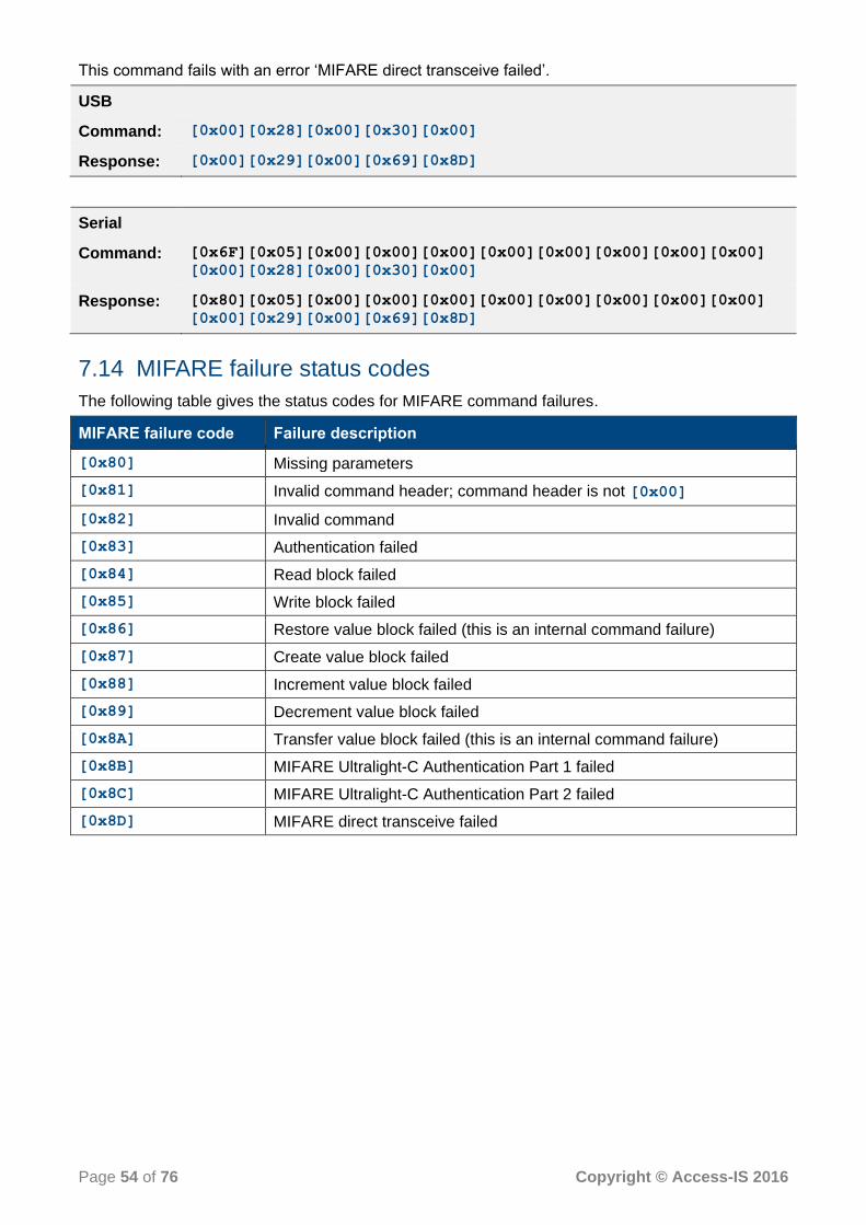
Page 54 of 76 Copyright © Access-IS 2016
This command fails with an error ‘MIFARE direct transceive failed’.
USB
Command: [0x00][0x28][0x00][0x30][0x00]
Response: [0x00][0x29][0x00][0x69][0x8D]
Serial
Command: [0x6F][0x05][0x00][0x00][0x00][0x00][0x00][0x00][0x00][0x00]
[0x00][0x28][0x00][0x30][0x00]
Response: [0x80][0x05][0x00][0x00][0x00][0x00][0x00][0x00][0x00][0x00]
[0x00][0x29][0x00][0x69][0x8D]
7.14 MIFARE failure status codes
The following table gives the status codes for MIFARE command failures.
MIFARE failure code Failure description
[0x80] Missing parameters
[0x81] Invalid command header; command header is not [0x00]
[0x82] Invalid command
[0x83] Authentication failed
[0x84] Read block failed
[0x85] Write block failed
[0x86] Restore value block failed (this is an internal command failure)
[0x87] Create value block failed
[0x88] Increment value block failed
[0x89] Decrement value block failed
[0x8A] Transfer value block failed (this is an internal command failure)
[0x8B] MIFARE Ultralight-C Authentication Part 1 failed
[0x8C] MIFARE Ultralight-C Authentication Part 2 failed
[0x8D] MIFARE direct transceive failed

Page 55 of 76 Copyright © Access-IS 2016
8. NFC management interface commands
The NFC module exposes an interface, known as the Management Interface. Your application software uses to manage and configure the NFC module. This section of the manual describes the command set and its responses.
Note: If there is a response to the command, the command is successful. If the command times out, it has failed.
USB-connected device
The Management Interface sends commands as HID reports.
The report length is always 64 bytes long, even if the commands are just a few bytes.
The NFC module ignores unused bytes at the end of the commands, but the recommendation is that you should initialise unused bytes to [0x00]. The example commands and responses omit
trailing zeroes.
Serial-connected device
The NFC module exposes a Management Interface on slot [0xFF].
The management commands are always less than 64 bytes long, while the responses are always 64 bytes long. Even though the response is just a few bytes, it is always padded with [0x00] to make it a 64-byte packet to preserve compatibility across different host interfaces.
All management commands use a CCID PC_to_RDR_XferBlock message to communicate
with the module. The application software should be aware of this and it should add/remove the CCID header as required.
Note: All commands have an attached CCID header, which is shown in black text in the examples. The example responses omit trailing zeroes.
8.1 Get firmware version
Use this command to retrieve the firmware version on the NFC module.
8.1.1 Management command bytes
Byte Command/Value Comments
0 [0x00] Command byte
1–63 [0x00] Unused bytes, set to [0x00]
8.1.2 Management response bytes
Byte Response/Value Comments
0 [0x00] Command echoed
1 Firmware major version
2 Firmware minor version
3–63 [0x00] Ignored (61 bytes)

Page 56 of 76 Copyright © Access-IS 2016
8.1.3 Example
This command retrieves the firmware version (0112).
USB
Command: [0x00]
Response: [0x00][0x01][0x12]
Serial
Command: [0x6F][0x01][0x00][0x00][0x00][0xFF][0x00][0x00][0x00][0x00]
[0x00]
Response: [0x80][0x36][0x00][0x00][0x00][0xFF][0x00][0x00][0x00][0x00]
[0x00][0x01][0x12]
8.2 Get bootloader version
Use this command to retrieve the bootloader version on the NFC module.
8.2.1 Management command bytes
Byte Command/Value Comments
0 [0x01] Command byte
1–63 [0x00] Unused bytes, set to [0x00]
8.2.2 Management response bytes
Byte Response/Value Comments
0 [0x01] Command echoed
1 Bootloader major version
2 Bootloader minor version
3–63 Ignored (61 bytes)
8.2.3 Example
This command retrieves the bootloader version (0106).
USB
Command: [0x01]
Response: [0x01][0x01][0x06]
Serial
Command: [0x6F][0x01][0x00][0x00][0x00][0xFF][0x00][0x00][0x00][0x00]
[0x01]
Response: [0x80][0x36][0x00][0x00][0x00][0xFF][0x00][0x00][0x00][0x00]
[0x01][0x01][0x06]

Page 57 of 76 Copyright © Access-IS 2016
8.3 Switch to bootloader
Use this command to switch to the bootloader to load new firmware. The module resets itself in bootloader mode soon after the sending the response.
Warning: Only use this command when loading new firmware. Using this command at any other time may cause the device to become inoperable.
8.3.1 Management command bytes
Byte Command/Value Comments
0 [0x02] Command byte
1–63 [0x00] Unused bytes, set to [0x00]
8.3.2 Management response bytes
Byte Response/Value Comments
0 [0x02] Command echoed
1 [0xAA]
2 [0x55]
3–63 [0x00] Ignored (61 bytes)
8.3.3 Example
This command switches to the bootloader and then resets the NFC module.
USB
Command: [0x02]
Response: [0x02][0xAA][0x55]
Serial
Command: [0x6F][0x01][0x00][0x00][0x00][0xFF][0x00][0x00][0x00][0x00]
[0x02]
Response: [0x80][0x36][0x00][0x00][0x00][0xFF][0x00][0x00][0x00][0x00]
[0x02][0xAA][0x55]
8.4 Get serial number
Use this command to retrieve the serial number of the NFC module.
8.4.1 Management command bytes
Byte Command/Value Comments
0 [0x03] Command byte
1–63 [0x00] Unused bytes, set to [0x00]
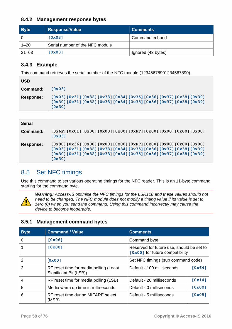
Page 58 of 76 Copyright © Access-IS 2016
8.4.2 Management response bytes
Byte Response/Value Comments
0 [0x03] Command echoed
1–20 Serial number of the NFC module
21–63 [0x00] Ignored (43 bytes)
8.4.3 Example
This command retrieves the serial number of the NFC module (12345678901234567890).
USB
Command: [0x03]
Response: [0x03][0x31][0x32][0x33][0x34][0x35][0x36][0x37][0x38][0x39]
[0x30][0x31][0x32][0x33][0x34][0x35][0x36][0x37][0x38][0x39]
[0x30]
Serial
Command: [0x6F][0x01][0x00][0x00][0x00][0xFF][0x00][0x00][0x00][0x00]
[0x03]
Response: [0x80][0x36][0x00][0x00][0x00][0xFF][0x00][0x00][0x00][0x00]
[0x03][0x31][0x32][0x33][0x34][0x35][0x36][0x37][0x38][0x39]
[0x30][0x31][0x32][0x33][0x34][0x35][0x36][0x37][0x38][0x39]
[0x30]
8.5 Set NFC timings
Use this command to set various operating timings for the NFC reader. This is an 11-byte command starting for the command byte.
Warning: Access-IS optimise the NFC timings for the LSR118 and these values should not need to be changed. The NFC module does not modify a timing value if its value is set to zero (0) when you send the command. Using this command incorrectly may cause the device to become inoperable.
8.5.1 Management command bytes
Byte Command / Value Comments
0 [0x06] Command byte
1 [0x00] Reserved for future use, should be set to [0x00] for future compatibility
2 [0x00] Set NFC timings (sub command code)
3 RF reset time for media polling (Least Significant Bit (LSB))
Default - 100 milliseconds [0x64]
4 RF reset time for media polling (LSB) Default - 20 milliseconds [0x14]
5 Media warm up time in milliseconds Default - 0 milliseconds [0x00]
6 RF reset time during MIFARE select (MSB)
Default - 5 milliseconds [0x05]

Page 59 of 76 Copyright © Access-IS 2016
Byte Command / Value Comments
7 RF reset time during MIFARE select (LSB)
Default - 5 milliseconds [0x05]
8 Media warm up time for MIFARE media Default - 0 milliseconds [0x00]
9 Command waiting time for MIFARE media (MSB)
Default - 250 milliseconds [0xFA]
10 Command waiting time for MIFARE media (LSB)
Default - 100 milliseconds [0x64]
8.5.2 Management response bytes
Byte Response/Value Comments
0 [0x06] Command echoed
1 [0x90] or [0x69] [0x90] - Success
[0x69] - Failure
2 [0x00]
3–63 61 unused bytes
8.5.3 Example
This command sets the ‘RF reset time for media polling (LSB)’ to 200 milliseconds.
USB
Command: [0x06][0x00][0x00][0x00][0xC8][0x00][0x00][0x00][0x00][0x00]
[0xC8]
Response: [0x06][0x90][0x00]
Serial
Command: [0x6F][0x0B][0x00][0x00][0x00][0xFF][0x00][0x00][0x00][0x00]
[0x06][0x00][0x00][0x00][0xC8][0x00][0x00][0x00][0x00][0x00]
[0xC8]
Response: [0x80][0x36][0x00][0x00][0x00][0xFF][0x00][0x00][0x00][0x00]
[0x06][0x90][0x00]
8.6 Get NFC timings
Use this command to get the operating timings of the NFC reader.
8.6.1 Management command bytes
Byte Command/Value Comments
0 [0x06] Command byte
1 [0x00] Reserved for future use, should be set to [0x00] for future compatibility
2 [0x80] Get NFC timings (sub command code)

Page 60 of 76 Copyright © Access-IS 2016
8.6.2 Management response bytes
Byte Response/Value Comments
0 [0x06] Command echoed
1 [0x00] Same as command byte 1
2 [0x80] Same as command byte 2
3 RF reset time for media polling (LSB) Default - 0 milliseconds [0x00]
4 RF reset time for media polling (LSB) Default - 100 milliseconds [0x64]
5 Media warm up time Default - 20 milliseconds [0x14]
6 RF reset time during MIFARE select (MSB)
Default - 0 milliseconds [0x00]
7 RF reset time during MIFARE select (LSB)
Default - 5 milliseconds [0x05]
8 Media warm up time for MIFARE media Default - 5 milliseconds [0x05]
9 Command waiting time for MIFARE media (MSB)
Default - 0 milliseconds [0x00]
10 Command waiting time for MIFARE media (LSB)
Default - 250 milliseconds [0xFA]
8.6.3 Example
This command retrieves the NFC timings from the device.
USB
Command: [0x06][0x00][0x80]
Response: [0x06][0x00][0x80][0x00][0x64][0x14][0x00][0x05][0x05][0x00]
[0xFA]
Serial
Command: [0x6F][0x02][0x00][0x00][0x00][0xFF][0x00][0x00][0x00][0x00]
[0x06][0x00][0x80]
Response: [0x80][0x36][0x00][0x00][0x00][0xFF][0x00][0x00][0x00][0x00]
[0x06][0x00][0x80][0x00][0x64][0x14][0x00][0x05][0x05][0x00]
[0xFA]
8.7 Enter sleep mode
Use this command to enter sleep mode and switch off the RF field. You may want to switch off the RF field when the device is not in use.
8.7.1 Management command bytes
Byte Command/Value Comments
0 [0x07] Command byte
1–63 [0x00] Unused bytes, set to [0x00]
Page 61 of 76 Copyright © Access-IS 2016
8.7.2 Management response bytes
Byte Response/Value Comments
0 [0x07] Command echoed
1 [0x90] or [0x69] [0x90] - Success
[0x69] - Failure
2 [0x00]
3–63 [0x00] Ignored (61 bytes)
8.7.3 Example
This command sets the device in sleep mode.
USB
Command: [0x07]
Response: [0x07][0x90][0x00]
Serial
Command: [0x6F][0x01][0x00][0x00][0x00][0xFF][0x00][0x00][0x00][0x00]
[0x07]
Response: [0x80][0x36][0x00][0x00][0x00][0xFF][0x00][0x00][0x00][0x00]
[0x07][0x90][0x00]
8.8 Exit sleep mode
Use this command to exit from sleep mode, turn RF on and resume normal operation.
8.8.1 Management command bytes
Byte Command/Value Comments
0 [0x09] Command byte
1–63 [0x00] Unused bytes, set to [0x00]
8.8.2 Management response bytes
Byte Response/Value Comments
0 [0x09] Command echoed
1 [0x90] or [0x69] [0x90] - Success
[0x69] - Failure
2 [0x00]
3–63 [0x00] Ignored (61 bytes)
Page 62 of 76 Copyright © Access-IS 2016
8.8.3 Example
This command exits sleep mode.
USB
Command: [0x09]
Response: [0x09][0x90][0x00]
Serial
Command: [0x6F][0x01][0x00][0x00][0x00][0xFF][0x00][0x00][0x00][0x00]
[0x09]
Response: [0x80][0x36][0x00][0x00][0x00][0xFF][0x00][0x00][0x00][0x00]
[0x09][0x90][0x00]
8.9 Get NFC kernel version
Use this command to retrieve the NFC kernel version of the NFC module.
8.9.1 Management command bytes
Byte Command/Value Comments
0 [0x0B] Command byte
1–63 [0x00] Unused bytes, set to [0x00]
8.9.2 Management response bytes
Byte Response/Value Comments
0 [0x0B] Command echoed
1 NFC kernel major version BCD hexadecimal value
2 NFC kernel minor version BCD hexadecimal value
3–63 [0x00] Ignored (61 bytes)
If both the major and minor kernel versions are [0x00], the NFC reader is not enabled in firmware.
If you believe this is in error, contact [email protected].
8.10 Get media serial number
Use this command to get the media serial number. Table 20 shows the data element returned by the reader for different types of media.
Table 20. Media types and data elements returned by the LSR118
Media type Data element
MIFARE 1K, 4K and Ultralight ISO14443-4 type A microprocessor card
Unique identifier (UID)
ISO14443-4 type B microprocessor card Pseudo-Unique PICC Identifier (PUPI)

Page 63 of 76 Copyright © Access-IS 2016
8.10.1 Management command bytes
Byte Command/Value Comments
0 [0x0D] Command byte
1–63 [0x00] Unused bytes, set to [0x00]
8.10.2 Management response bytes
Byte Response/Value Comments
0 [0x0D] Command echoed
1 Media type value See Table 21
2 Number of valid bytes to follow Specifies the number of bytes in the serial number
3–xx Media serial number Most significant bit first
xx–63 Ignored (unused bytes)
8.10.3 Example
This command retrieves the serial number from the media. The detected media type is MIFARE Ultralight.
USB
Command: [0x0D]
Response: [0x0D][0x05][0x07][0x04][0xBC][0xB8][0xD2][0x3B][0x3C][0x80]
Serial
Command: [0x6F][0x01][0x00][0x00][0x00][0xFF][0x00][0x00][0x00][0x00]
[0x0D]
Response: [0x80][0x36][0x00][0x00][0x00][0xFF][0x00][0x00][0x00][0x00]
[0x0D][0x05][0x07][0x04][0xBC][0xB8][0xD2][0x3B][0x3C][0x80]
8.10.4 Media type values
The value of byte 2 indicates the media type as shown in the following table.
Table 21. Media type values for supported (and non-supported) media types
Media type Type value Current support
No media present [0x00] Yes
ISO14443-4 A [0x01] Yes
ISO14443-4 B [0x02] Yes
MIFARE Classic 1K [0x03] Yes
MIFARE Classic 4K [0x04] Yes
MIFARE Ultralight [0x05] Yes
MIFARE Plus [0x06] Yes
Felica media [0x07] No

Page 64 of 76 Copyright © Access-IS 2016
Media type Type value Current support
ISO15693 [0x08] No
NFC Type 1 Tag [0x09] No
NFC DEP media [0x0A] No
8.11 Disable media arrival and removal notifications
Use this command to disable the media arrival/removal notifications sent from the NFC module; the NFC module becomes a slave unit. The application software should poll for the card by sending the Get media serial number command (on page 62).
Note: This command is applicable only to the serial host interface. This command fails if sent to a USB device.
8.11.1 Management command bytes
Byte Command/Value Comments
0 [0x0E] Command byte
1 Slot ID As defined in Communicating with individual readers (on page 32)
2 [0x01] Disables notifications Any other value enables notifications
8.11.2 Management response bytes
Byte Response/Value Comments
0 [0x0E] Command echoed
1 [0x90] or [0x69] [0x90] - Success
[0x69] - Failure
2 [0x00]
3–63 Ignored (unused bytes)
8.11.3 Example
This command disables notifications from the NFC reader.
Command: [0x6F][0x01][0x00][0x00][0x00][0xFF][0x00][0x00][0x00][0x00]
[0x0E][0x00][0x01]
Response: [0x80][0x36][0x00][0x00][0x00][0xFF][0x00][0x00][0x00][0x00]
[0x0E][0x90][0x00]

Page 65 of 76 Copyright © Access-IS 2016
8.12 Set serial interface baud rate
Use this command to change the serial interface baud rate. If the command succeeds, then subsequent commands are sent using the new baud rate.
Note: This command is applicable only to the serial host interface. This command fails if sent to a USB device.
Byte Command/Value Comments
0 [0x10] Command byte
1 [0x00] - > 9600 Kbps
[0x01] - > 19200 Kbps
[0x02] - > 38400 Kbps
[0x03] - > 57600 Kbps
[0x04] - > 115200 Kbps (Default)
[0x05] - > 153600 Kbps
[0x06] - > 211200 Kbps
[0x07] - > 230400 Kbps
[0x08] - > 460800 Kbps
[0x09] - > 921600 Kbps
Sets the required baud rate
2 [0x55] Signature bytes
3 [0x5A]
4 [0xA5]
5 [0xAA]
8.12.1 Management response bytes
Byte Response/Value Comments
0 [0x10] Command echoed
1 [0x90] or [0x69] [0x90] - Success, new baud rate
accepted [0x69] - Failure, no change in baud rate
2 [0x00]
3–63 Ignored (unused bytes)
8.12.2 Example
This command sets the baud rate to 57600 Kbps.
Command: [0x6F][0x01][0x00][0x00][0x00][0xFF][0x00][0x00][0x00][0x00]
[0x10][0x03][0x55][0x5A][0xA5][0xAA]
Response: [0x80][0x36][0x00][0x00][0x00][0xFF][0x00][0x00][0x00][0x00]
[0x10][0x90][0x00]

Page 66 of 76 Copyright © Access-IS 2016
A. NFC module serial number matching
The NFC module in the LSR118 exposes a maximum of five CCID smartcard readers and one HID interface for management. It may be possible that a system is connected to two or more modules. In this scenario, the application software should perform serial number matching to determine which readers are physically present together in one module. The interfaces with same serial numbers are physically present together in one module.
The serial number of a CCID reader can be read using the SCardGetAttrib function.
The following piece of code shows an example of the SCardGetAttrib function.
// connect to smart card reader
lReturn = SCardConnect( hSC,
(LPCWSTR)pCardReaderName,
SCARD_SHARE_DIRECT,
NULL,
&hCardHandle,
NULL );
if ( SCARD_S_SUCCESS != lReturn )
{
Console::WriteLine("Failed SCardConnect\n");
exit(1); // Or other appropriate action.
}
// get reader serial no
LPBYTE pbAttr = NULL;
DWORD cByte = SCARD_AUTOALLOCATE;
lReturn = SCardGetAttrib(hCardHandle,
SCARD_ATTR_VENDOR_IFD_SERIAL_NO,
(LPBYTE)&pbAttr,
&cByte);
if ( SCARD_S_SUCCESS != lReturn )
{
Console::WriteLine("Failed to retrieve Reader Serial\n");
exit(1); // Or other appropriate action.
}
printf("serial no: %s", pbAttr);
For more information on the SCardGetAttrib function, please refer to the Microsoft website.
Similar to the CCID readers, you can retrieve the serial number of the HID interface using the HidD_GetSerialNumberString function. Please refer to the Microsoft website for more
information on HidD_GetSerialNumberString.

Page 67 of 76 Copyright © Access-IS 2016
B. HID reports – barcode only
B.1 Receive data
Data received from the LSR118 will be in a HID input report, structured as below:
Bit
Byte 7 6 5 4 3 2 1 0
0 Report ID = 2
1 Length of data field
2 AIM symbology Identifier (always ‘]’)
3 AIM symbology Identifier 1
4 AIM symbology Identifier 2
5 Data from LSR118 (up to 56 bytes)
..
..
..
..
60
61 Further symbology identifier
62 Reserved
63 - - - - - - - Data cont’d
B.1.1 Example HID input reports, as sent by the device
In this example, the decoded barcode contained 60 bytes of data, which the device split into two HID reports. Note that byte 63 in 0x01 in the first report and 0x00 in the second report indicates whether to expect more data or not. In the second packet, the remaining 52 bytes of data are set to 0x00.
Bit
Byte 7 6 5 4 3 2 1 0
0 [0x02]
1 [0x38] - (56)
2 [0x5D] - ‘]’
3 [0x51] - ‘Q’
4 [0x30] - ‘0’
5 M1GATHERGOOD/M ICHAEL YABCDE F LHRDURAK 354 2 052Y003D23[0x20][0x20]
..
..
60
61 [0x73] - ‘s’
62 [0x00]
63 0 0 0 0 0 0 0 1
Byte 7 6 5 4 3 2 1 0

Page 68 of 76 Copyright © Access-IS 2016
Bit
0 [0x02]
1 [0x04]
2 [0x5D] - ‘]’
3 [0x51] - ‘Q’
4 [0x30] - ‘0’
5 [0x20]100 [0x00] [0x00] ... [0x00] [0x00]
..
..
60
61 [0x73] - ‘s’
62 [0x00]
63 0 0 0 0 0 0 0 0
B.2 Send commands
To send commands to the LSR118, use a HID out report with the following structure:
Bit
Byte 7 6 5 4 3 2 1 0
0 Report ID = 253
1 Data length
2 Output data (up to 62 bytes)
..
..
..
..
63
B.2.1 Example output report to request firmware version
This example requests the firmware version from the LSR118.
Bit
Byte 7 6 5 4 3 2 1 0
0 253
1 [0x0B]
2 [0x16][0x4D][0x0D]AISFWV1.
..
..
..
..
63

Page 69 of 76 Copyright © Access-IS 2016
B.3 Trigger controls
To set the device status to activate the ‘read’ lights on the device, send an HID output report with the following structure:
Bit
Byte 7 6 5 4 3 2 1 0
0 Report ID = 4
1 - Activate ‘Good Read’ light (Green)
Activate ‘Bad Read’ light (Red)
- - Initiate barcode read (trigger)
Prevent barcode read (untrigger)
-
Note: You can only use ‘trigger’ and ‘untrigger’ commands in Interactive mode. ‘Good Read’ and ‘Bad Read’ indicator controls are only available in Host or Interactive modes.

Page 70 of 76 Copyright © Access-IS 2016
C. NFC module example code and API functions
This section presents code snippets for the NFC module process flow (see Figure 9 on page 31). The main API functions in are shown in red.
C.1 Initialise smartcard sub-system
// Try to establish the Smartcard sub-system context while(SCardEstablishContext(SCARD_SCOPE_SYSTEM, NULL, NULL, &hRFIDContext) != SCARD_S_SUCCESS) {
Sleep(1000); // Wait for some time and retry } // Optional: List all the readers available in the smartcard sub-system // If the reader name is already known then this step is not required. However, there may // be more than one reader connected to the system. Hence it is recommended to list all the // readers and select the one that is required RcvLength = 128; memset(Reader_Tracker_Buffer, 0 , sizeof(Reader_Tracker_Buffer)); while(SCardListReaders(hRFIDContext, NULL, (LPSTR)_Buffer, &RcvLength) != SCARD_S_SUCCESS) { Sleep(1000); // Wait for some time and retry }
C.2 Poll for card arrival
if(SCardGetStatusChange(hRFIDContext, INFINITE, RdrState, 1) == SCARD_S_SUCCESS) { if(RdrState[0].dwEventState & SCARD_STATE_PRESENT) { MessageBox(“Card Present”); } else if(RdrState[0].dwEventState & SCARD_STATE_EMPTY) { MessageBox(“Card Removed”); } } else {
MessageBox(“Reader removed”); }
C.3 Connect to the card
if(SCardConnect(hRFIDContext, _str, SCARD_SHARE_EXCLUSIVE, SCARD_PROTOCOL_T0 | SCARD_PROTOCOL_T1, &hCrd, &dwProtocol) != SCARD_S_SUCCESS) { // Unable to connect to card
MessageBox(“Unable to connect to card”); } else {
// Connected to card MessageBox(“Connected to card”);
}

Page 71 of 76 Copyright © Access-IS 2016
C.4 Get ATR of the card
RcvLength = 128; if(SCardStatus(hCrd, (LPSTR)_Buffer, &RcvLength, NULL, NULL, ATR, &_ATRLen) != SCARD_S_SUCCESS) {
SCardDisconnect(hCrd, SCARD_LEAVE_CARD); MessageBox(“Unable to get ATR of card”);
} else {
MessageBox(“ATR successful”); }
C.5 Communicate with card
RcvLength = RX_BUFFER_SIZE; if(SCardTransmit(hCrd, &SendPci, TX_Buffer, Transmit_Length, NULL, RX_Buffer, &RcvLength) != SCARD_S_SUCCESS) {
MessageBox(“Communication failed”); } else { MessageBox(“Communication successful”); }
C.6 Determine if ATR indicates MIFARE type
Refer to MIFARE cards on page 36.
C.7 Disconnect the card
SCardDisconnect(hCrd, SCARD_LEAVE_CARD);

Page 72 of 76 Copyright © Access-IS 2016
D. ASCII character reference
DEC HEX Symbol Description
0 00 NUL Null char
1 01 SOH Start of heading
2 02 STX Start of text
3 03 ETX End of text
4 04 EOT End of transmission
5 05 ENQ Enquiry
6 06 ACK Acknowledgment
7 07 BEL Bell
8 08 BS Back space
9 09 HT Horizontal tab
10 0A LF Line feed
11 0B VT Vertical tab
12 0C FF Form feed
13 0D CR Carriage return
14 0E SO Shift out / X-on
15 0F SI Shift in / X-off
16 10 DLE Data line escape
17 11 DC1 Device control 1 (oft. XON)
18 12 DC2 Device control 2
19 13 DC3 Device control 3 (oft. XOFF)
20 14 DC4 Device control 4
21 15 NAK Negative acknowledgement
22 16 SYN Synchronous idle
23 17 ETB End of transmit block
24 18 CAN Cancel
25 19 EM End of medium
26 1A SUB Substitute
27 1B ESC Escape
28 1C FS File separator
29 1D GS Group separator
30 1E RS Record separator
31 1F US Unit separator
32 20 SPACE Space
33 21 ! Exclamation mark
34 22 " Double quotes (or speech marks)
35 23 # Number
36 24 $ Dollar

Page 73 of 76 Copyright © Access-IS 2016
DEC HEX Symbol Description
37 25 % Percent sign
38 26 & Ampersand
39 27 ' Single quote
40 28 ( Open parenthesis (or open bracket)
41 29 ) Close parenthesis (or close bracket)
42 2A * Asterisk
43 2B + Plus
44 2C , Comma
45 2D - Hyphen
46 2E . Period, dot or full stop
47 2F / Slash or divide
48 30 0 Zero
49 31 1 One
50 32 2 Two
51 33 3 Three
52 34 4 Four
53 35 5 Five
54 36 6 Six
55 37 7 Seven
56 38 8 Eight
57 39 9 Nine
58 3A : Colon
59 3B ; Semicolon
60 3C < Less than (or open angled bracket)
61 3D = Equals
62 3E > Greater than (or close angled bracket)
63 3F ? Question mark
64 40 @ At symbol
65 41 A Uppercase A
66 42 B Uppercase B
67 43 C Uppercase C
68 44 D Uppercase D
69 45 E Uppercase E
70 46 F Uppercase F
71 47 G Uppercase G
72 48 H Uppercase H
73 49 I Uppercase I
74 4A J Uppercase J
75 4B K Uppercase K
76 4C L Uppercase L

Page 74 of 76 Copyright © Access-IS 2016
DEC HEX Symbol Description
77 4D M Uppercase M
78 4E N Uppercase N
79 4F O Uppercase O
80 50 P Uppercase P
81 51 Q Uppercase Q
82 52 R Uppercase R
83 53 S Uppercase S
84 54 T Uppercase T
85 55 U Uppercase U
86 56 V Uppercase V
87 57 W Uppercase W
88 58 X Uppercase X
89 59 Y Uppercase Y
90 5A Z Uppercase Z
91 5B [ Opening bracket
92 5C \ Backslash
93 5D ] Closing bracket
94 5E ^ Caret - circumflex
95 5F _ Underscore
96 60 ` Grave accent
97 61 a Lowercase a
98 62 b Lowercase b
99 63 c Lowercase c
100 64 d Lowercase d
101 65 e Lowercase e
102 66 f Lowercase f
103 67 g Lowercase g
104 68 h Lowercase h
105 69 i Lowercase i
106 6A j Lowercase j
107 6B k Lowercase k
108 6C l Lowercase l
109 6D m Lowercase m
110 6E n Lowercase n
111 6F o Lowercase o
112 70 p Lowercase p
113 71 q Lowercase q
114 72 r Lowercase r
115 73 s Lowercase s
116 74 t Lowercase t
Page 75 of 76 Copyright © Access-IS 2016
DEC HEX Symbol Description
117 75 u Lowercase u
118 76 v Lowercase v
119 77 w Lowercase w
120 78 x Lowercase x
121 79 y Lowercase y
122 7A z Lowercase z
123 7B { Opening brace
124 7C | Vertical bar
125 7D } Closing brace
126 7E ~ Tilde
127 7F DEL Delete

Page 76 of 76 Copyright © Access-IS 2016
E. Document history
Issue Date Description
1.0 15.03.2016 First issue.