subgrade requirements for fabricated geomembranes
TRANSCRIPT
Fabricated Geomembrane Institute 1 University of Illinois at Urbana-Champaign Subgrade Preparation Guideline Urbana, IL 61801 7/12/2010
Subgrade Requirements for Fabricated Geomembranes
Fabricated Geomembrane Institute July 12, 2010
The soil subgrade shall be reviewed and approved by the engineer or his/her qualified delegate prior to placement of the geomembrane. This shall be accomplished by observing the amount of deflection and/or rutting which occurs under the wheels of loaded construction equipment. Areas of excessive deformation, e.g., excessive pumping or rutting, greater than 2 inches (50 mm) and areas which appear wet at the surface, frozen, or otherwise unstable shall be corrected by excavation of the unstable area and replacement. Alternately, the engineer may specify a different method of stabilization. Soils used to replace unstable areas shall be approved by the engineer prior to placement.
Approved subgrade should be of sufficient quality to support the weight of installation equipment, e.g., 4x4 forklift, rubber-tracked bobcat, etc.
Daily evaluation of the subgrade after preparation must show that no changes have occurred, e.g., rain, before placement of the geomembrane.
Sources for subgrade material shall be free of any organics, vegetation, debris, foreign material, and other deleterious material.
Sticks, sharp objects, hard nodules, subsurface voids, soft areas, excess silt, protrusion, or debris of any kind should not be present (See Figure 1).
If coarse grained material is encountered, appropriate bedding should be used to protect the geomembrane. This bedding should consist of compacted finer material with a depth of 150 mm (6”) minimum. Where bedding sand is not available, a non-woven cushion geotextile may be used if it is designed for puncture protection.
Subgrade surface must be free of all rocks and stones for the following types of geomembranes:
Fabricated Geomembrane Institute 2 University of Illinois at Urbana-Champaign Subgrade Preparation Guideline Urbana, IL 61801 7/12/2010
Reinforced Geomembranes (> 20 mil) 3/8-inch (10 mm) diameter maximum particle size typically and manufacturer should be contacted if greater than 3/8-inch (10 mm) diameter maximum
Light Reinforced Geomembranes (< 20 mil) less than 3/8-inch (10 mm) diameter particle size manufacturer should be contacted if greater than 3/8-inch (10 mm) diameter maximum
Unsupported Poly Geomembranes 1/2-inch (13 mm) diameter maximum particle size typically manufacturer should be contacted if greater than 1/2-inch (13 mm) diameter maximum
Unsupported Compounded Geomembranes (PVC, alloys, and rubbers) 1-inch (25 mm) diameter maximum particle size typically manufacturer should be contacted if greater than 1-inch (25 mm) diameter maximum.
Larger rock sizes may be possible but site specific puncture resistance tests should be conducted to determine if a cushion geotextile is required. Cushion geotextiles can be effective in protecting a geomembrane from puncture. An extreme example is shown in Figure 2 with a 0.75 mm (30 mil) thick PVC geomembrane installed with a geotextile protection fabric of 540 g/m2 (16 oz/yd2) being placed on 100 mm diameter ballasted rock subgrade. However, it is generally not recommended to place a geomembrane on a rock subgrade as shown in Figure 2.
Subgrade surface needs to be smooth, flat, firm, and unyielding with no sudden, sharp, or abrupt changes or break in grade.
The natural groundwater/piezometric level should be established (current and future) and if it is higher than the base of the excavation adequate drainage should be installed to prevent water pressure from building up below the liner. Possible site specific solutions include one of the following:
o Drainage material, a minimum of 100 mm thick. o Underdrain system.
Venting is recommended unless other site conditions exist to allow dissipation of gas pressure from beneath the liner. One such condition is the presence of granular foundation soils (SW, GW or GP). A minimum vent spacing of 50 feet (15.2 m) is recommended.
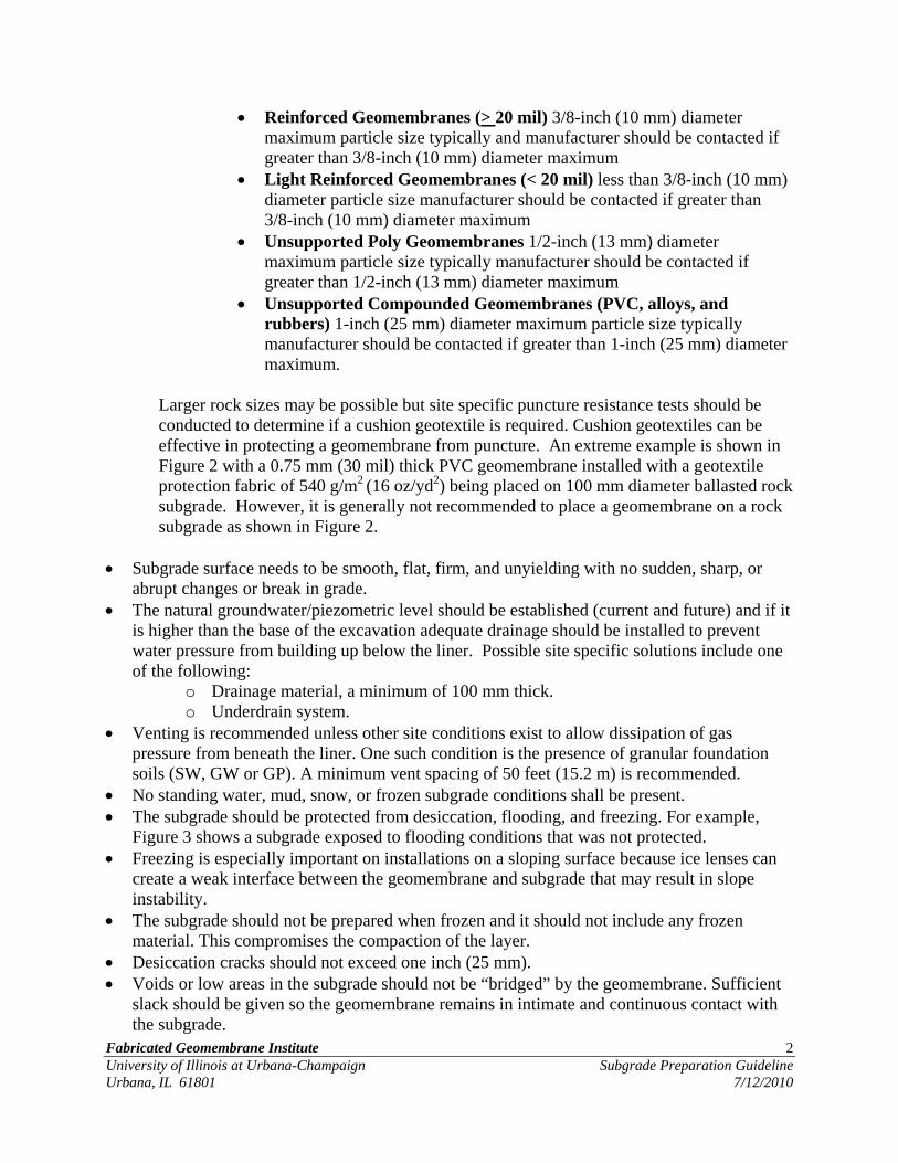
No standing water, mud, snow, or frozen subgrade conditions shall be present. The subgrade should be protected from desiccation, flooding, and freezing. For example,
Figure 3 shows a subgrade exposed to flooding conditions that was not protected. Freezing is especially important on installations on a sloping surface because ice lenses can
create a weak interface between the geomembrane and subgrade that may result in slope instability.
The subgrade should not be prepared when frozen and it should not include any frozen material. This compromises the compaction of the layer.
Desiccation cracks should not exceed one inch (25 mm). Voids or low areas in the subgrade should not be “bridged” by the geomembrane. Sufficient
slack should be given so the geomembrane remains in intimate and continuous contact with the subgrade.

Fabricated Geomembrane Institute 3 University of Illinois at Urbana-Champaign Subgrade Preparation Guideline Urbana, IL 61801 7/12/2010
Figures 4, 5, and 6 show examples of unacceptable, almost acceptable, and good subgrade examples respectively, to illustrate various subgrade conditions.
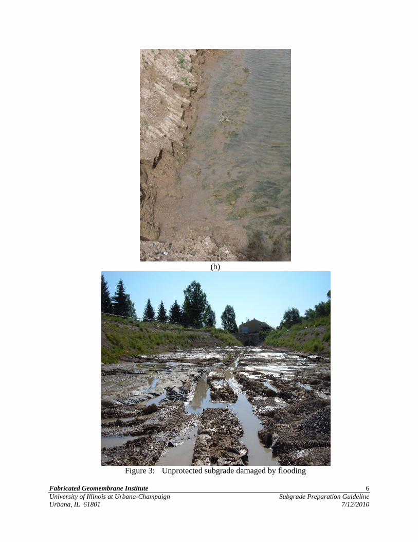
Subgrade surface should be drum smooth rolled prior to liner installation (see Figure 6). The geomembrane should not be placed on a surface derived from a sheepsfoot roller (see foreground of Figure 5).
The subgrade surface needs to be compacted to a minimum of 95% of Relative Compaction based on the Standard Proctor Test, or 90% based on Modified Proctor Test.
o Weak or compressible areas that cannot be satisfactorily compacted should be removed and replaced. Sand blinding or an approved cushion geotextile may be used as protection.
o Surface should be compacted at a moisture content that achieves the required permeability and dry unit weight.
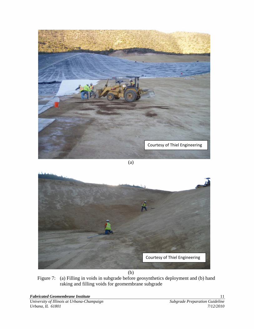
Subgrade damaged by construction equipment shall be repaired prior to placement. Figure 7(a) presents an example of a good subgrade preparation that was compromised by construction equipment. Figure 7(a) also shows the subgrade being repaired prior to geomembrane placement.
Slope stability is a site specific issue because many factors can adversely impact slope stability. Generally, a slope inclination less than 3 horizontal to 1 vertical is needed, especially in damp or freezing weather. Site specific shear testing and slope stability analyses of underlying and overlying soils and interfaces should be performed to ensure a stable slope. The slope inclination should be verified prior to placement of the geomembrane.
(a)

Fabricated Geomembrane Institute 4 University of Illinois at Urbana-Champaign Subgrade Preparation Guideline Urbana, IL 61801 7/12/2010
(b)
Figure 1: (a) Example of unacceptable clod sizes and protruding elements and (b) example of unacceptable protrusion size

Fabricated Geomembrane Institute 5 University of Illinois at Urbana-Champaign Subgrade Preparation Guideline Urbana, IL 61801 7/12/2010
Figure 2: 0.75 mm thick PVC geomembrane with a geotextile protection fabric of 540 g/m2
being placed on a 100 mm-diameter ballasted rock subgrade.
Fabricated Geomembrane Institute 6 University of Illinois at Urbana-Champaign Subgrade Preparation Guideline Urbana, IL 61801 7/12/2010
(b)
Figure 3: Unprotected subgrade damaged by flooding

Fabricated Geomembrane Institute 7 University of Illinois at Urbana-Champaign Subgrade Preparation Guideline Urbana, IL 61801 7/12/2010
(a)
(b)
(c)

Fabricated Geomembrane Institute 8 University of Illinois at Urbana-Champaign Subgrade Preparation Guideline Urbana, IL 61801 7/12/2010
Figure 4: Examples (a), (b), and (c) of unacceptable subgrade surfaces for geomembrane placement
Figure 5: Almost-acceptable subgrade in the foreground.
Fabricated Geomembrane Institute 9 University of Illinois at Urbana-Champaign Subgrade Preparation Guideline Urbana, IL 61801 7/12/2010
(a) Example of acceptable drum smooth rolled surface
(b) Example of acceptable drum smooth rolled surface
Courtesy of Thiel Engineering

Fabricated Geomembrane Institute 10 University of Illinois at Urbana-Champaign Subgrade Preparation Guideline Urbana, IL 61801 7/12/2010
(c) Example of acceptable drum smooth rolled surface
Figure 6: Examples (a), (b), and (c) of good subgrade preparation. Repairs must be
performed if construction equipment compromises the surface.
Fabricated Geomembrane Institute 11 University of Illinois at Urbana-Champaign Subgrade Preparation Guideline Urbana, IL 61801 7/12/2010
(a)
(b)
Figure 7: (a) Filling in voids in subgrade before geosynthetics deployment and (b) hand raking and filling voids for geomembrane subgrade
Courtesy of Thiel Engineering
Courtesy of Thiel Engineering

Fabricated Geomembrane Institute 12 University of Illinois at Urbana-Champaign Subgrade Preparation Guideline Urbana, IL 61801 7/12/2010
Acknowledgments: This guideline was prepared with the assistance of FGI Members and University of Illinois Graduate Students Melissa Berena and Luis Pazmino under the supervision of Professor Timothy D. Stark.