subaru/volvo dl 1981-84 volkswagen dl (sedan) 1985-89 …
TRANSCRIPT
4 5
Locate the factory wiring harness in the dash. Metra recommends using the proper mating adaptor and making connections as shown. (Isolate and individually tape off the ends of any unused wires to prevent electrical short circuit).
Re-connect the battery terminal and test the unit for proper operation. Mount the head unit/kit assembly to the sub-dash with those screws previously removed in step #1.
A
B
C
D
A) Strip wire ends back ½"B) Twist ends togetherC) Solder D) Tape
3b
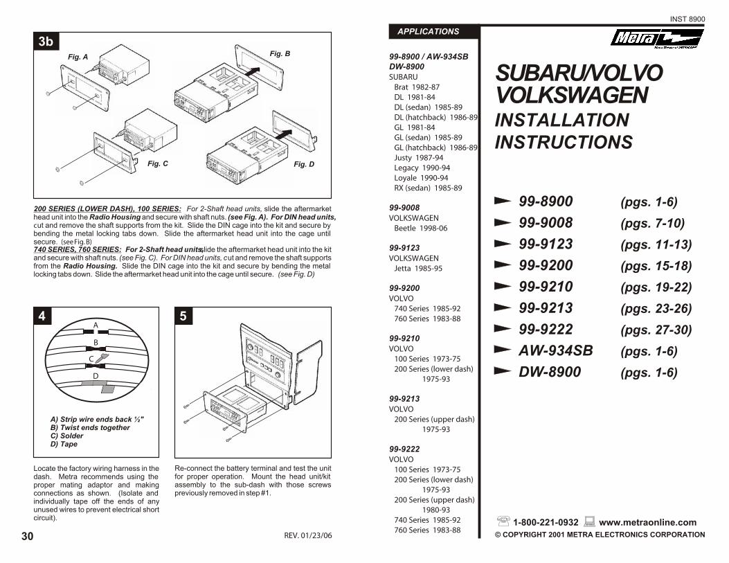
200 SERIES (LOWER DASH), 100 SERIES: For 2-Shaft head units, slide the aftermarket head unit into the Radio Housing and secure with shaft nuts. (see Fig. A). For DIN head units, cut and remove the shaft supports from the kit. Slide the DIN cage into the kit and secure by bending the metal locking tabs down. Slide the aftermarket head unit into the cage until secure. (see Fig. B)740 SERIES, 760 SERIES: For 2-Shaft head units, slide the aftermarket head unit into the kit and secure with shaft nuts. (see Fig. C). For DIN head units, cut and remove the shaft supports from the Radio Housing. Slide the DIN cage into the kit and secure by bending the metal locking tabs down. Slide the aftermarket head unit into the cage until secure. (see Fig. D)
Fig. A Fig. B
Fig. C Fig. D
REV. 01/23/0630
SUBARU/VOLVOVOLKSWAGENINSTALLATIONINSTRUCTIONS
APPLICATIONSINST 8900
99-8900 (pgs. 1-6) 99-9008 (pgs. 7-10) 99-9123 (pgs. 11-13) 99-9200 (pgs. 15-18) 99-9210 (pgs. 19-22) 99-9213 (pgs. 23-26) 99-9222 (pgs. 27-30) AW-934SB (pgs. 1-6) DW-8900 (pgs. 1-6)
99-8900 / AW-934SBDW-8900SUBARU Brat 1982-87 DL 1981-84 DL (sedan) 1985-89 DL (hatchback) 1986-89 GL 1981-84 GL (sedan) 1985-89 GL (hatchback) 1986-89 Justy 1987-94 Legacy 1990-94 Loyale 1990-94 RX (sedan) 1985-89
99-9008VOLKSWAGEN Beetle 1998-06
99-9123VOLKSWAGEN Jetta 1985-95
99-9200VOLVO 740 Series 1985-92 760 Series 1983-88
99-9210VOLVO 100 Series 1973-75 200 Series (lower dash)
1975-93
99-9213VOLVO 200 Series (upper dash)
1975-93
99-9222VOLVO 100 Series 1973-75 200 Series (lower dash)
1975-93 200 Series (upper dash)
1980-93 740 Series 1985-92 760 Series 1983-88
1-800-221-0932 www.metraonline.com © COPYRIGHT 2001 METRA ELECTRONICS CORPORATION

1
VOLVO 740 Series 1985-92 760 Series 1983-88
Locate Radio Housing #3. Skip to the Installation Instructions for ALL VEHICLES on Page #3.
2
Disconnect the negative battery terminal to prevent an accidental short circuit. Remove (3) screws from the steering column inspection panel and lower the panel. Remove the factory radio knobs and shaft nuts. Insert a flat-blade screwdriver into the shaft wells and push in on the side springs. Pull the factory radio out and disconnect the wiring.
ALL VEHICLES
3a
200 SERIES (UPPER DASH): For 2-Shaft head units, attach the Spacer* to the Radio Housing. Slide the aftermarket head unit into the kit and secure with shaft nuts. (see Fig. A). For DIN head units, cut and remove the shaft supports from the Spacer* and Radio Housing. Slide the DIN cage into the kit and secure by bending the metal locking tabs down. Slide the aftermarket head unit into the cage until secure. (see Fig. B)
Fig. A
*OPTIONAL
Fig. B
*OPTIONAL
29

KIT COMPONENTS
Faceplate #2
Faceplate #3
(4) Oval-head Screws
(2) Hex-head Screws
Equalizer Dummy Plate
Faceplate #4
Mounting Brackets (Justy)
(4) Speed Clips
TOOLS REQUIRED
Cutting tool
Socket wrench
Phillips screwdriver
APPLICATIONS
CAR PAGESUBARU Brat 1982-87...............................................................2 DL 1981-84................................................................. 2 DL (sedan) 1985-89.....................................................3 DL (hatchback) 1986-89.............................................. 3 GL 1981-84................................................................. 2 GL (sedan) 1985-89.....................................................3 GL (hatchback) 1986-89.............................................. 3 Justy 1987-94............................................................. 4 Legacy 1990-94...........................................................5 Loyale 1990-94........................................................... 3 RX (sedan) 1985-89.................................................... 3
Faceplate #1
99-8900AW-934SBDW-8900INSTALLATION INSTRUCTIONS
128
1
VOLVO 100 Series 1973-75 200 Series (lower dash) 1975-93
Locate Radio Housing #1. Skip to the Installation Instructions for ALL VEHICLES on Page #30.
2
1
VOLVO 200 Series (upper dash) 1980-93
2
Locate Radio Housing #2. Skip to the Installation Instructions for ALL VEHICLES on Page #29.
Disconnect the negative battery terminal to prevent an accidental short circuit. Remove (1) Phillips screw and (1) plastic twist-lock screw securing each side panel to the lower dash console. Remove (2) Phillips screws from the base of the radio trim bezel and remove the bezel. Remove (4) screws securing the factory pocket to the sub-dash and remove the pocket.
Disconnect the negative battery terminal to prevent an accidental short circuit. Unclip the square trim piece located to the left of the factory radio opening and remove (2) screws exposed. Open the glove box and remove (7) screws exposed in the glove box cavity. Remove the glove box assembly. Remove (1) screw securing the rear support to the factory head unit. Slide the head unit out and disconnect the wiring.
1-800-221-0932 www.metraonline.com © COPYRIGHT 2001 METRA ELECTRONICS CORPORATION

27
Disconnect the negative battery terminal to prevent an accidental short circuit. Remove (4) screws securing the dash console, lift the console out and disconnect the wiring.
1
SUBARU Brat 1982-87 / DL 1981-84 GL 1981-84
3
2
2
Locate the Mounting Brackets, Shaft Masks and Faceplate #2.
Using a dremel tool, cut the plastic along the scribed lines ("A") until the shaft holes and nose hole is formed. (see Fig. A). Attach the Shaft Masks to Faceplate #2. Slide the aftermarket head unit through the holes in the console and kit and secure with shaft nuts. (see Fig. B). Skip to the Installation Instructions for ALL VEHICLES on Page #6.
Fig. A
Fig. B
KIT COMPONENTS
Radio Housing #1
Radio Housing #2
Radio Housing #3
Spacer
TOOLS REQUIRED
Cutting tool
Flat-blade screwdriver
Phillips screwdriver
99-9222INSTALLATION INSTRUCTIONS
APPLICATIONS
CAR PAGEVOLVO 100 Series 1973-75..................................................... 28 200 Series (lower dash) 1975-93..................................28 200 Series (upper dash) 1980-93.................................28 740 Series 1985-92..................................................... 29 760 Series 1983-88..................................................... 29
1-800-221-0932 www.metraonline.com © COPYRIGHT 2001 METRA ELECTRONICS CORPORATION

26 3
Disconnect the negative battery terminal to prevent an accidental short circuit. Unclip the radio trim bezel and remove. Remove (3) Phillips screws securing the trip computer and remove. Remove (7) Phillips screws securing the factory radio assembly and disconnect the wiring.
1
SUBARU DL 1985-89 / GL 1985-89 / RX (sedan) 1985-89 DL (hatchback) 1986-89 / GL (hatchback) 1986-89
Loyale 1990-94
3
Locate Faceplate #1.
2
2-SHAFT HEAD UNITS: Slide the aftermarket head unit into Faceplate #1 and secure with shaft nuts. (see Fig. A). Skip to the Installation Instrcutions for ALL VEHICLES on Page #5.
DIN HEAD UNITS: Cut and remove the shaft supports from Faceplate #1. Slide the DIN cage into the kit and secure by bending the metal locking tabs down. Slide the aftermarket head unit into the cage until secure. (see Fig. B). Skip to the Installation Instructions for ALL VEHICLES on Page #6.
(If an equalizer will be included, slide the unit into the back of Faceplate #1 and secure. If an equalizer will NOT be included, snap the Equalizer Dummy Plate into the opening).
Fig. A
Fig. B
NOTES: ______________________________________________________
________________________________________________________________
________________________________________________________________
________________________________________________________________
________________________________________________________________
________________________________________________________________
________________________________________________________________
________________________________________________________________
________________________________________________________________
________________________________________________________________
________________________________________________________________
________________________________________________________________
________________________________________________________________
________________________________________________________________
________________________________________________________________
________________________________________________________________
________________________________________________________________
________________________________________________________________
________________________________________________________________
________________________________________________________________
________________________________________________________________
________________________________________________________________

4 25
Disconnect the negative battery terminal to prevent an accidental short circuit. Remove the ashtray and (3) screws exposed on the retaining bracket. Remove the climate control knobs. Using a small screwdriver, pry out on the climate control control cover and remove (2) screws exposed. Remove (2) screws above the ashtray bracket. Unclip the radio trim bezel. Disconnect the clock and cigarette lighter wiring and remove the bezel. Remove the screws securing the factory head unit and disconnect the wiring.
1
SUBARU Justy 1987-94
2
3
Locate the Mounting Brackets, Shaft Masks and Faceplate #4.
Fig. A
2-SHAFT HEAD UNITS: Slide the aftermarket head unit through the Faceplate #4 and the Mounting Brackets and secure with shaft nuts. (see Fig. A). Skip to the Installation Instructions for ALL VEHICLES on Page #5.
DIN HEAD UNITS: Cut and remove the shaft supports from Faceplate #4. Skip to the Installation Instructions for ALL VEHICIES on Page #6.
3
Locate the factory wiring harness in the dash. Metra recommends using the proper mating adaptor and making connections as shown. (Isolate and individually tape off the ends of any unused wires to prevent electrical short circuit).
A
B
C
D
A) Strip wire ends back ½"B) Twist ends togetherC) Solder D) Tape
5
Re-connect the battery terminal and test the unit for proper operation. Mount the head uni t/kit assembly to the sub-dash with (2) screws previously removed.
Locate the (2) mounting positions in the sub-dash ("A").
4
"A"

Disconnect the negative battery terminal to prevent an accidental short circuit. Remove the cupholder and (2) screws exposed. Remove the ashtray and (2) screws exposed on the ashtray bracket. Unclip the radio trim bezel and remove. Remove the screws securing the factory head unit and disconnect the wiring.
1
SUBARU Legacy 1990-94
Locate Faceplate #3.
2
3
2-SHAFT HEAD UNITS: Slide the aftermarket head unit into Faceplate #3 and secure with shaft nuts. (see Fig. A). Skip to the Installation Instructions for ALL VEHICLES on Page #6.
Fig. A
Disconnect the negative battery terminal to prevent an accidental short circuit. Unclip the square trim piece located to the left of the factory radio opening and remove (2) screws exposed. Open the glove box and remove (7) screws exposed in the glove box cavity. Remove the glove box assembly. Remove (1) screw securing the rear support to the factory head unit. Slide the head unit out and disconnect the wiring.
SHAFT UNITS: Attach the Spacer* to the Radio Housing. Slide the aftermarket head unit into the kit and secure with shaft nuts. (see Fig. A)
DIN HEAD UNITS: Cut and remove the shaft supports from the Spacer* and Radio Housing. Slide the DIN cage into the kit and secure by bending the metal locking tabs down. Slide the aftermarket head unit into the cage until secure. (see Fig. B)
1
2Fig. A
ALL VEHICLES
Fig. B
*OPTIONAL
*OPTIONAL
24 5

5 6
Locate the factory wiring harness in the dash. Metra recommends using the proper mating adaptor and making connections as shown. (Isolate and individually tape off the ends of any unused wires to prevent electrical short circuit).
DL 1981-84, GL 1981-84, BRAT: Re-connect the battery terminal and test the unit for proper operation. Mount the console assembly to the dash with (4) screws previously removed in step #1. (see Fig. A)DL 1985-89, GL 1985-89, LOYALE, RX: Re-connect the battery terminal and test the unit for proper operation. Mount the head unit/kit assembly to the sub-dash with (4) Oval-head Screws and (4) Speed Clips supplied. (see Fig. B)JUSTY: Re-connect the battery terminal and test the unit for proper operation. For 2-shaft head units, mount the head unit/kit assembly to the sub-dash with (2) Phillips screws previously removed in step #1. For DIN head units, slide the DIN cage through the Faceplate and into the sub-dash and secure by bending the metal locking tabs down. Slide the aftermarket head unit into the cage until secure. (see Fig. C) LEGACY: Re-connect the battery terminal and test the unit for proper operation. Mount the head unit/kit assembly to the sub-dash with (2) Hex-head Screws suppied. (see Fig. D)
A
B
C
D
A) Strip wire ends back ½"B) Twist ends togetherC) Solder D) Tape
ALL VEHICLES
Fig. A
Fig. B
Fig. DFig. C
KIT COMPONENTS
KIT FEATURES
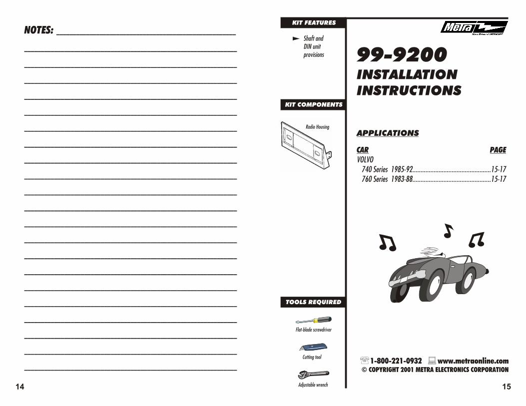
Shaft and DIN unit provisions
Various mounting depth alternatives
99-9213INSTALLATION INSTRUCTIONS
APPLICATIONS
CAR PAGEVOLVO 200 Series (upper dash) 1975-93............................23-26
TOOLS REQUIRED
Cutting tool
Adjustable wrench
Phillips screwdriver
Radio Housing
Spacer
6 23
1-800-221-0932 www.metraonline.com © COPYRIGHT 2001 METRA ELECTRONICS CORPORATION

99-9008INSTALLATIONINSTRUCTIONS
KIT COMPONENTS
TOOLS REQUIRED
Torx-head screwdriver
86-9001 - Head unit removal keys
Faceplate "B"
APPLICATIONS
CAR PAGEVOLKSWAGEN Beetle 1998-06.......................................................7-10
Faceplate "A"
KIT FEATURES
DIN andISO-DIN headunit provisions
ISO-DIN Brackets
NOTES: ______________________________________________________
________________________________________________________________
________________________________________________________________
________________________________________________________________
________________________________________________________________
________________________________________________________________
________________________________________________________________
________________________________________________________________
________________________________________________________________
________________________________________________________________
________________________________________________________________
________________________________________________________________
________________________________________________________________
________________________________________________________________
________________________________________________________________
________________________________________________________________
________________________________________________________________
________________________________________________________________
________________________________________________________________
________________________________________________________________
________________________________________________________________
________________________________________________________________
22 7
1-800-221-0932 www.metraonline.com © COPYRIGHT 2001 METRA ELECTRONICS CORPORATION
Radio Housing

3
Locate the factory wiring harness in the dash. Metra recommends using the proper mating adaptor and making connections as shown. (Isolate and individually tape off the ends of any unused wires to prevent electrical short circuit).
A
B
C
D
A) Strip wire ends back ½"B) Twist ends togetherC) Solder D) Tape
5
Re-connect the battery terminal and test the unit for proper operation. Mount the head uni t/kit assembly to the sub-dash with (4) screws previously removed.
Locate the (4) mounting positions in the sub-dash ("A").
4
"A"
DIN HEAD UNITS: Position the Radio Housing with the side notches in the upper corners ("A"). Slide the DIN cage into the Housing and slide the assembly into the sub-dash. Secure the DIN cage by bending the metal locking tabs down. Mount the Housing to the sub-dash with (2) torx-head screws removed in step #2. (see Fig. A)ISO-DIN HEAD UNITS: Align the holes in the ISO-DIN Brackets with the holes in the ISO-DIN head unit and mount the Brackets to the head unit with the screws included with the unit. (see Fig. B). Screws provided with certain head units may create a clearance problem during the head unit installation (step #5). It may be necessary in these cases to trim the walls of the dash bezel to provide the proper clearance.
3
IF YOU WISH TO INSTALL THE AFTERMARKET HEAD UNIT WITHOUT THE TRIMRING *
Remove the trimring from the aftermarket head unit.
1
AFTERMARKET HEAD UNITS ARE USUALLY EQUIPPED WITH A TRIMRING SURROUNDING THE FACE OF THE UNIT. SINCE SOME INSTALLERS PREFER A TRIMRING AND OTHERS DO NOT, THIS KIT WAS DESIGNED TO ALLOW THE INSTALLER TO CHOOSE.
*IN SOME CASES, IT MAY BE NECESSARY TO CUT THE TRIMRING AWAY FROM THE HEAD UNIT.
Insert the long ends of Metra's 86-9001 into the slots in the factory head unit, pull the unit out and disconnect the wiring. Remove (2) torx-head screws exposed in the dash cavity.
2
Fig. A
Fig. B
"A"
8 21

5
DIN HEAD UNITS: Re-connect the battery terminal and test the unit for proper operation. Slide the aftermarket DIN head unit into the cage until secure. (see Fig. A)ISO-DIN HEAD UNITS: Re-connect the battery terminal and test the unit for proper operation. Slide the aftermarket ISO-DIN unit into the dash. (see Fig. B).
4
Locate the factory wiring harness in the dash. Metra recommends using the proper mating adaptor and making connections as shown. (Isolate and individually tape off the ends of any unused wires to prevent electrical short circuit).
A
B
C
D
A) Strip wire ends back ½"B) Twist ends togetherC) Solder D) Tape
6
DIN HEAD UNITS: Place Faceplate "A" over the mounted head unit and push it into the Radio Housing until the side clips engage. (see Fig. A)ISO-DIN HEAD UNITS: Position the Radio Housing with the side notches in the upper corners ("B"). Mount the Housing over the head unit with (2) torx-head screws removed in step #2. (see Fig. B)
Fig. A
Fig. A
Fig. B
Fig. B
"B"
Disconnect the negative battery terminal to prevent an accidental short circuit. Remove (1) Phillips screw and (1) plastic twist-lock screw securing each side panel to the lower dash console. Remove (2) Phillips screws from the base of the radio trim bezel and remove the bezel. Remove (4) screws securing the factory pocket to the sub-dash and remove the pocket.
SHAFT UNITS: Slide the aftermarket head unit into the Radio Housing and secure with shaft nuts. (see Fig. A)
DIN HEAD UNITS: Cut and remove the shaft supports from the Radio Housing. Slide the DIN cage into the kit and secure by bending the metal locking tabs down. Slide the aftermarket head unit into the cage until secure. (see Fig. B)
1
2
Fig. A
ALL VEHICLES
Fig. B
20 9

Place Faceplate "B" in the sub-dash opening, slide the DIN cage into the Faceplate and secure by bending the metal locking tabs down.
Insert the long ends of Metra's 86-9001 into the slots in the factory head unit and pull the unit out. Disconnect the wiring.
1
IF YOU WISH TO INSTALL THE AFTERMARKET HEAD UNIT WITH THE TRIMRING
2
3
Locate the factory wiring harness in the dash. Metra recommends using the proper mating adaptor and making connections as shown. (Isolate and individually tape off the ends of any unused wires to prevent electrical short circuit).
A
B
C
D
A) Strip wire ends back ½"B) Twist ends togetherC) Solder D) Tape
4
Re-connect the battery terminal and test the unit for proper operation. Slide the aftermarket DIN head unit into the cage until secure.
KIT COMPONENTS
KIT FEATURES
Shaft and DIN unit provisions 99-9210
INSTALLATION INSTRUCTIONS
APPLICATIONS
CAR PAGEVOLVO 100 Series 1973-75................................................19-23 200 Series (lower dash) 1975-93............................19-23
Radio Housing
TOOLS REQUIRED
Cutting tool
Adjustable wrench
Phillips screwdriver
10 19
1-800-221-0932 www.metraonline.com © COPYRIGHT 2001 METRA ELECTRONICS CORPORATION

NOTES: ______________________________________________________
________________________________________________________________
________________________________________________________________
________________________________________________________________
________________________________________________________________
________________________________________________________________
________________________________________________________________
________________________________________________________________
________________________________________________________________
________________________________________________________________
________________________________________________________________
________________________________________________________________
________________________________________________________________
________________________________________________________________
________________________________________________________________
________________________________________________________________
________________________________________________________________
________________________________________________________________
________________________________________________________________
________________________________________________________________
________________________________________________________________
________________________________________________________________
KIT COMPONENTS
KIT FEATURES
Shaft unit provisions
Faceplate
TOOLS REQUIRED
Cutting tool
Adjustable wrench
Flat-blade screwdriver
Snap-in Bracket
99-9123INSTALLATION INSTRUCTIONS
APPLICATIONS
CAR PAGEVOLKSWAGEN Jetta 1985-95........................................................11-13
18 11
1-800-221-0932 www.metraonline.com © COPYRIGHT 2001 METRA ELECTRONICS CORPORATION
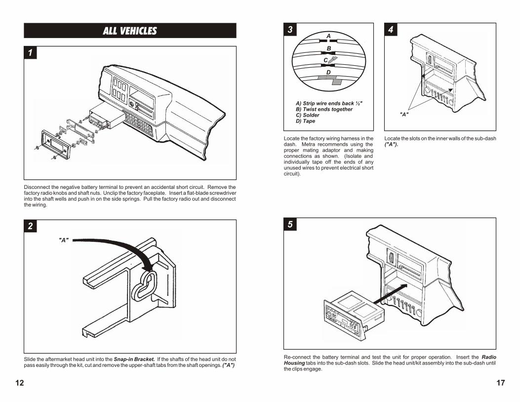
Disconnect the negative battery terminal to prevent an accidental short circuit. Remove the factory radio knobs and shaft nuts. Unclip the factory faceplate. Insert a flat-blade screwdriver into the shaft wells and push in on the side springs. Pull the factory radio out and disconnect the wiring.
Slide the aftermarket head unit into the Snap-in Bracket. If the shafts of the head unit do not pass easily through the kit, cut and remove the upper-shaft tabs from the shaft openings. ("A")
1
2
"A"
ALL VEHICLES 3
Locate the factory wiring harness in the dash. Metra recommends using the proper mating adaptor and making connections as shown. (Isolate and individually tape off the ends of any unused wires to prevent electrical short circuit).
A
B
C
D
A) Strip wire ends back ½"B) Twist ends togetherC) Solder D) Tape
5
Re-connect the battery terminal and test the unit for proper operation. Insert the Radio Housing tabs into the sub-dash slots. Slide the head unit/kit assembly into the sub-dash until the clips engage.
Locate the slots on the inner walls of the sub-dash ("A").
4
"A"
12 17

Attach the Faceplate to the Snap-in Bracket. Slide the aftermarket head unit into the kit and secure with shaft nuts.
3 4
Locate the factory wiring harness in the dash. Metra recommends using the proper mating adaptor and making connections as shown. (Isolate and individually tape off the ends of any unused wires to prevent electrical short circuit).
A
B
C
D
A) Strip wire ends back ½"B) Twist ends togetherC) Solder D) Tape
5
Re-connect the battery terminal and test the unit for proper operation. Snap the head uni t/kit assembly into the sub-dash.
Disconnect the negative battery terminal to prevent an accidental short circuit. Remove (3) screws from the steering column inspection panel and lower the panel. Remove the factory radio knobs and shaft nuts. Insert a flat-blade screwdriver into the shaft wells and push in on the side springs. Pull the factory radio out and disconnect the wiring.
SHAFT UNITS: Slide the aftermarket head unit into the Radio Housing and secure with shaft nuts. (see Fig. A)
DIN HEAD UNITS: Cut and remove the shaft supports from the Radio Housing. Slide the DIN cage into the kit and secure by bending the metal locking tabs down. Slide the aftermarket head unit into the cage until secure. (see Fig. B)
1
2
Fig. A
Fig. B
ALL VEHICLES
16 13
KIT COMPONENTS
KIT FEATURES
Shaft and DIN unit provisions
TOOLS REQUIRED
Cutting tool
Adjustable wrench
Flat-blade screwdriver
99-9200INSTALLATION INSTRUCTIONS
APPLICATIONS
CAR PAGEVOLVO 740 Series 1985-92................................................15-17 760 Series 1983-88................................................15-17
Radio Housing
NOTES: ______________________________________________________
________________________________________________________________
________________________________________________________________
________________________________________________________________
________________________________________________________________
________________________________________________________________
________________________________________________________________
________________________________________________________________
________________________________________________________________
________________________________________________________________
________________________________________________________________
________________________________________________________________
________________________________________________________________
________________________________________________________________
________________________________________________________________
________________________________________________________________
________________________________________________________________
________________________________________________________________
________________________________________________________________
________________________________________________________________
________________________________________________________________
________________________________________________________________
14 15
1-800-221-0932 www.metraonline.com © COPYRIGHT 2001 METRA ELECTRONICS CORPORATION