sub-thz radio-over-fiber signal generation using external
TRANSCRIPT
Sub-THz radio-over-fibersignal generation usingexternal modulation
Tetsuya Kawanishi1,2a), Takahide Sakamoto2, and Atsushi Kanno21 Faculty of Science and Engineering, Waseda University,
3–4–1 Okubo, Shinjuku-ku, Tokyo 169–8255, Japan2 National Institute of Information and Communications Technology,
4–2–1 Nukui-Kitamachi, Koganei, Tokyo 184–8795, Japan
Abstract: This paper describes photonic technologies for millimeter-wave
generation and distribution. External modulation would be useful for stable
and high-quality radio-over-fiber signal generation, where frequency stability
and spurious suppression are very important for radio services such as
mobile communications, radio locations etc. This paper provides outline of
radio-over-fiber signal generation techniques. Precise and high-speed light-
wave optical modulation would play important roles for suppression of
undesired spectrum components. Photonic harmonic generation would be
useful for very high-frequency signals. Reciprocating optical modulators
consisting of optical modulators and fiber Bragg gratings can provide optical
modulation by sub-THz signals.
Keywords: radio over fiber, optical modulation, millimeter-wave
Classification: Optoelectronics, Lasers and quantum electronics, Ultrafast
optics, Silicon photonics, Planar lightwave circuits
References
[1] Recommendation ITU-R P.676-10.[2] T. Kawanishi, A. Kanno, T. Kuri and N. Yamamoto: IEEE Photonics Society
Newsletter 28 (2014) 4.[3] A. Kohmura, S. Futatsumori, N. Yonemoto and K. Okada: 6th European Radar
Conference (2013) 44.[4] T. Kawanishi, S. Sakamoto and M. Izutsu: IEEE J. Sel. Top. Quantum Electron.
13 (2007) 79. DOI:10.1109/JSTQE.2006.889044[5] G. L. Li and P. K. L. Yu: J. Lightwave Technol. 21 (2003) 2010. DOI:10.1109/
JLT.2003.815654[6] H. Ito, T. Furuta, Y. Hirota, T. Ishibashi, A. Hirata, T. Nagatsuma, H. Matsuo,
T. Noguchi and M. Ishiguro: Electron. Lett. 38 (2002) 989. DOI:10.1049/el:20020667
[7] S. Ho-Jin, A. Ajito, Y. Muramoto, A. Wakatsuki, T. Nagatsuma and N.Kukutsu: IEEE Microw. Wireless Compon. Lett. 22 (2012) 363. DOI:10.1109/LMWC.2012.2201460
[8] P. G. Huggard, B. N. Ellison, P. Shen, N. J. Gomes, P. A. Davies, W. Shillue,A. Vaccari and J. M. Payne: Electron. Lett. 38 (2002) 327. DOI:10.1049/el:20020202
© IEICE 2015DOI: 10.1587/elex.12.20152004Received May 6, 2015Accepted May 27, 2015Published July 10, 2015
1
REVIEW PAPER IEICE Electronics Express, Vol.12, No.13, 1–12

[9] P. A. Davies, A. P. Foord and K. E. Razavi: Electron. Lett. 31 (1995) 1754.DOI:10.1049/el:19951220
[10] H. Kiuchi, T. Kawanishi, M. Yamada, T. Sakamoto, M. Tsuchiya, J. Amagaiand M. Izutsu: IEEE Trans. Microw. Theory Techn. 55 (2007) 1964. DOI:10.1109/TMTT.2007.904070
[11] R. J. Steed, L. Ponnampalam, M. J. Fice, M. J. C. C. Renaud, D. C. Rogers,D. G. Moodie, G. D. Maxwell, I. F. Lealman, M. J. Robertson, L. Pavlovic, L.Naglic, M. Vidmar and A. J. Seeds: IEEE J. Sel. Top. Quantum Electron. 17(2011) 210. DOI:10.1109/JSTQE.2010.2049003
[12] M. Hyodo, S. Saito and Y. Kasai: Electron. Lett. 45 (2009) 878. DOI:10.1049/el.2009.0801
[13] T. Kawanishi, T. Sakamoto, M. Tsuchiya and M. Izutsu: 19th Annual Meetingof the IEEE Lasers and Electro-Optics Society (2006) 195. DOI:10.1109/LEOS.2006.278977
[14] T. Kawanishi, M. Sasaki, S. Shimotsu, S. Oikawa and M. Izutsu: IEEE Photon.Technol. Lett. 13 (2001) 854. DOI:10.1109/68.935826
[15] T. Kawanishi, T. Sakamoto, S. Shinada and M. Izutsu: IEEE Microw. WirelessCompon. Lett. 14 (2004) 566. DOI:10.1109/LMWC.2004.837377
[16] T. Kawanishi, S. Oikawa, K. Yoshiara, T. Sakamoto, S. Shinada and M. Izutsu:IEEE Photon. Technol. Lett. 17 (2005) 669. DOI:10.1109/LPT.2004.842377
[17] T. Kawanishi, T. Sakamoto and M. Izutsu: European Conference on OpticalCommunications (2006) We4.6.4. DOI:10.1109/ECOC.2006.4801432
[18] APT Report, APT/ASTAP/REPT-11.
1 Introduction
Millimeter-wave including sub-THz region would be attractive for various radio
services, such as very high-speed wireless links, high-resolution radars, etc.,
because wide radio-wave spectra are available in millimeter-wave bands, such as
V-band (50–75GHz), E-band (60–90GHz) and W-band (75–110GHz), while it is
rather difficult to reserve such wide bands in microwave regions. Unlicensed bands
in 60GHz attract much attention for high-speed short distance telecommunications.
However, 60GHz bands are not suitable for moderate or long distance links due
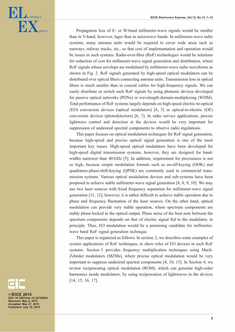
to oxygen absorption. On the other hand, in the range from 70GHz to 110GHz
(E- and W-bands), atmospheric attenuation of millimeter-waves is much smaller
than in 60GHz bands, as shown in Fig. 1 [1]. Attenuation in dry air is the lowest at
94GHz in the frequency region higher than 60GHz. In this range, 71–76GHz,
81–86GHz, 92–94GHz, 94.1–100GHz and 102–109.5GHz are internationally
allocated for fixed or mobile radio services (95–100GHz is only for mobile services
in USA). In total, 25.4GHz wide frequency bands can be used for moderate
distance wireless telecommunication services in Europe and Japan, where over
100Gb/s wireless links can be constructed with modulation formats with spectral
efficiency larger than 3.94 bit/s/Hz [2]. In these bands, a 8GHz wide continuous
spectrum from 92GHz to 100GHz is available for radar applications, such as high-
resolution imaging for foreign-object debris (FOD) detection, which is required to
increase safety in transportation infrastructure including runways in airports and
facilities along railway tracks [3].© IEICE 2015DOI: 10.1587/elex.12.20152004Received May 6, 2015Accepted May 27, 2015Published July 10, 2015
2
IEICE Electronics Express, Vol.12, No.13, 1–12
Propagation loss of E- or W-band millimeter-wave signals would be smaller
than in V-band, however, lager than in microwave bands. In millimeter-wave radio
systems, many antenna units would be required to cover wide areas such as
runways, railway trucks, etc., so that cost of implementation and operation would
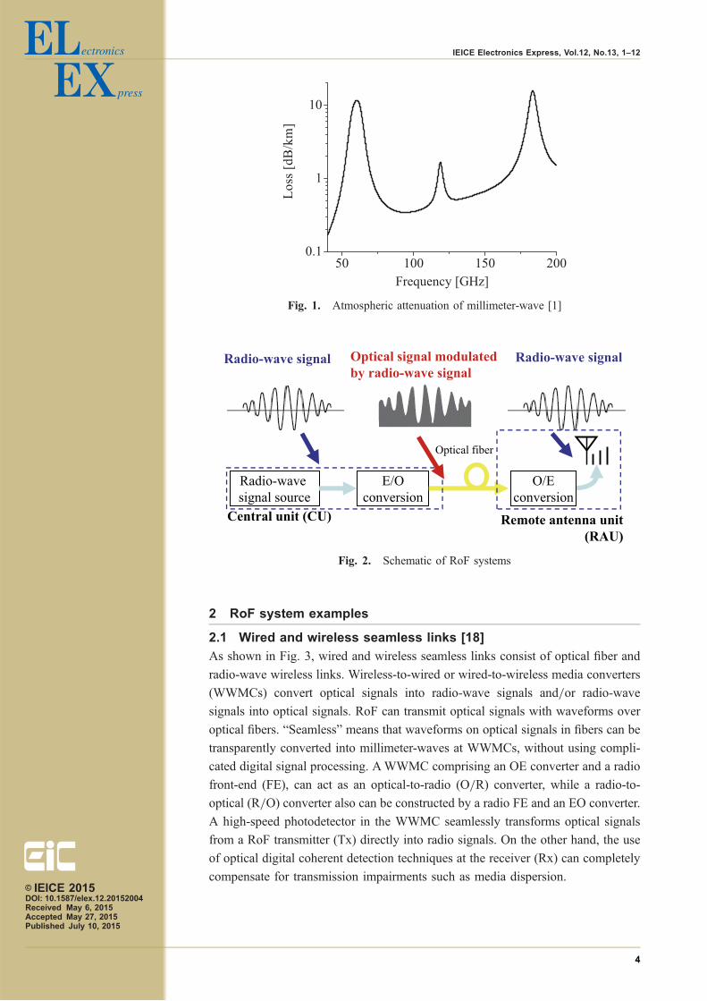
be issues in such systems. Radio-over-fiber (RoF) technologies would be solutions
for reduction of cost for millimeter-wave signal generation and distribution, where
RoF signals whose envelops are modulated by millimeter-wave radio waveforms as
shown in Fig. 2. RoF signals generated by high-speed optical modulators can be
distributed over optical fibers connecting antenna units. Transmission loss in optical
fibers is much smaller than in coaxial cables for high-frequency signals. We can
easily distribute or switch such RoF signals by using photonic devices developed
for passive optical networks (PONs) or wavelength-domain-multiplexing (WDM).
Total performance of RoF systems largely depends on high-speed electric-to-optical
(EO) conversion devices (optical modulators) [4, 5] or optical-to-electric (OE)
conversion devices (photodetectors) [6, 7]. In radio service applications, precise
lightwave control and detection at the devices would be very important for
suppression of undesired spectral components to observe radio regulations.
This paper focuses on optical modulation techniques for RoF signal generation,
because high-speed and precise optical signal generation is one of the most
important key issues. High-speed optical modulators have been developed for
high-speed digital transmission systems, however, they are designed for band-
widths narrower than 40GHz [5]. In addition, requirement for preciseness is not
so high, because simple modulation formats such as on-off-keying (OOK) and
quadrature-phase-shift-keying (QPSK) are commonly used in commercial trans-
mission systems. Various optical modulation devices and sub-systems have been
proposed to achieve stable millimeter-wave signal generation [4, 8, 9, 10]. We may
use two laser sources with fixed frequency separation for millimeter-wave signal
generation [11, 12], however, it is rather difficult to achieve stable operation due to
phase and frequency fluctuation of the laser sources. On the other hand, optical
modulation can provide very stable operation, where spectrum components are
stably phase-locked in the optical output. Phase noise of the beat note between the
spectrum components depends on that of electric signal fed to the modulator, in
principle. Thus, EO modulation would be a promising candidate for millimeter-
wave band RoF signal generation technique.
This paper is organized as follows. In section 2, we describes some examples of
system applications of RoF techniques, to show roles of EO devices in such RoF
systems. Section 3 provides frequency multiplication techniques using Mach-
Zehnder modulators (MZMs), where precise optical modulation would be very
important to suppress undesired spectral components [4, 10, 13]. In Section 4, we
review reciprocating optical modulation (ROM), which can generate high-order
harmonics inside modulators, by using reciprocation of lightwaves in the devices
[14, 15, 16, 17].
© IEICE 2015DOI: 10.1587/elex.12.20152004Received May 6, 2015Accepted May 27, 2015Published July 10, 2015
3
IEICE Electronics Express, Vol.12, No.13, 1–12
2 RoF system examples
2.1 Wired and wireless seamless links [18]
As shown in Fig. 3, wired and wireless seamless links consist of optical fiber and
radio-wave wireless links. Wireless-to-wired or wired-to-wireless media converters
(WWMCs) convert optical signals into radio-wave signals and/or radio-wave
signals into optical signals. RoF can transmit optical signals with waveforms over
optical fibers. “Seamless” means that waveforms on optical signals in fibers can be
transparently converted into millimeter-waves at WWMCs, without using compli-
cated digital signal processing. AWWMC comprising an OE converter and a radio
front-end (FE), can act as an optical-to-radio (O/R) converter, while a radio-to-
optical (R/O) converter also can be constructed by a radio FE and an EO converter.
A high-speed photodetector in the WWMC seamlessly transforms optical signals
from a RoF transmitter (Tx) directly into radio signals. On the other hand, the use
of optical digital coherent detection techniques at the receiver (Rx) can completely
compensate for transmission impairments such as media dispersion.
Fig. 1. Atmospheric attenuation of millimeter-wave [1]
Fig. 2. Schematic of RoF systems
© IEICE 2015DOI: 10.1587/elex.12.20152004Received May 6, 2015Accepted May 27, 2015Published July 10, 2015
4
IEICE Electronics Express, Vol.12, No.13, 1–12

2.2 Millimeter-wave distribution systems for radar systems
High resolution imaging which can detect metal objects as small as a few
centimeters would be needed to ensure take-off and landing safety in airports
where the typical length and width of runways are 60m and 3000m, respectively.
Areas along tracks longer than 100 km should be scanned with resolution much
smaller than 1m, to monitor railway facilities. However, millimeter-wave attenu-
ation in the air is not small enough to achieve radar range long enough for airport or
railway facility surveillance. Required radiation power is proportional to the fourth
power of the radar range. It is rather difficult to achieve high-power millimeter-
wave signals by semiconductor devices. We may consider another option to
increase the radar range: to use a number of radar units (radar heads) installed
close to the areas under surveillance. For a linear area along to a railway track or
runway (linear cell), N units can cover N times longer area, while a system with a
radar unit needs at least N4 times larger radiation power to achieve N times longer
range. A radar system consisting of many radar heads can largely reduce total
radiation power of the system and required millimeter-wave output at each unit, so
that the high-resolution imaging for long area coverage can be achieved by low-
cost semiconductor devices. However, the system needs many high performance
millimeter-wave oscillators for radar ranging by each unit. A RoF system compris-
ing one or a few master generators and radar heads connected by optical fibers has
been proposed to overcome this problem, where RoF signals can be delivered from
a central office to each remote radar head through optical fibers network [3].
3 Over 100GHz RoF two-tone signal generation using Mach-Zehnder
modulators [10, 13]
Mach-Zehnder modulators (MZMs) can generate stable upper sideband (USB) and
lower sideband (LSB) components, by feeding sinusoidal electric signals. The
output spectrum depends on the dc bias voltage applied on the electrode in the
MZM. When the bias is set to a minimum transmission point, double-sideband
suppressed carrier (DSB-SC) optical modulation can be achieved, where the output
Fig. 3. Schematic of wired and wireless seamless links [2]
© IEICE 2015DOI: 10.1587/elex.12.20152004Received May 6, 2015Accepted May 27, 2015Published July 10, 2015
5
IEICE Electronics Express, Vol.12, No.13, 1–12

has the first order LSB and USB. The frequency separation between the two
spectral components is precisely equal to double the modulating signal frequency
[4]. The spectral components generated by optical modulation are always phase-
locked, so that we can easily construct robust systems without using complicated
feedback control techniques. However, the modulation frequency is limited by the
frequency response of the modulator. A typical 3 dB bandwidth of a modulator is
30GHz, so that the frequency upper limit of the two-tone signal generated by DSB-
SC modulation can not be larger than 100GHz. An MZM whose bias was set to a
maximum transmission point was used to generate the second order LSB and USB.
By using this technique, we can easily obtain a high-frequency two-tone signal,
however, the suppression ratio of undesired components depends on the extinction
ratio of the MZM. Recently, we proposed ultra high extinction-ratio modulation
technique by using an integrated MZM having intensity trimmers [4].
When the bias of the MZM is at the maximum transmission point, the odd order
sideband components were suppressed. Thus, the output would have the zeroth
order component, whose optical frequency is identical to that of the input, and the
second order components (LSB and USB), when the higher order components can
be neglected. By eliminating the zeroth order component, we can obtain a two-tone
lightwave signal of 4fm, where fm is the frequency of the rf signal applied to the
modulator. The frequency separation between the zeroth and second order compo-
nents is 2fm. When fm > 10GHz, the frequency separation would be large enough
to eliminate the zeroth order by using a conventional optical filter. The suppression
ratio of the first order components depends on the extinction-ratio of the MZM. By
using the modulator with intensity trimmers, we can suppress, largely, the first order
components, which cause undesired spurious signal generation. 40GHz sinusoidal
signal was fed to the modulator. The optical output had the zeroth and second order
components, where the suppression ratio of the first order components with respect
to the zeroth order was 34 dB. The zeroth order component was eliminated by the
optical band rejection filter whose bandwidth was 25GHz. The optical signal was
boosted by the optical amplifier, where a 5 nm band-pass filter was used to suppress
spontaneous emission noise. As shown in Fig. 4, we successfully obtained a two-
Fig. 4. Optical spectrum of 160GHz two-tone signal generated by ahigh extinction ratio MZM
© IEICE 2015DOI: 10.1587/elex.12.20152004Received May 6, 2015Accepted May 27, 2015Published July 10, 2015
6
IEICE Electronics Express, Vol.12, No.13, 1–12

tone lightwave signal whose frequency separation was 160GHz. We also measured
a time domain profile of the two-tone signal by using an optical sampling
oscilloscope (ANDO AQ7750). The output was quite stable, where the period
was 6.25 ps and the extinction ratio was larger than 10 dB, as shown in Fig. 5.
4 Reciprocating optical modulation for over 300GHz signal gener-
ation [17]
A reciprocating optical modulator (ROM), consisting of a pair of optical filters and
an optical phase modulator, as shown in Fig. 6, can generate high-order sideband
components effectively, where one of the optical filter is placed at the optical input
port (input filter), and the other is at the output port (output filter) [14]. In ROMs,
some of the sideband components are fed to the optical modulator again, in order to
obtain effective generation of specific sideband components. The desired sideband
components are taken out from the modulator, without recycling to the modulator.
This is in contrast to mode-locked lasers, where all generated sideband components
are recycled into the modulators. ROMs can generate very stable and low-phase
noise signals by using hybrid integration [15, 16].
Fig. 5. Time domain profile of 160GHz two-tone signal generated by ahigh extinction ratio MZM
Fig. 6. Schematic of ROM© IEICE 2015DOI: 10.1587/elex.12.20152004Received May 6, 2015Accepted May 27, 2015Published July 10, 2015
7
IEICE Electronics Express, Vol.12, No.13, 1–12

In order to obtain very high-frequency components over 300GHz, input and
output filters should have wide reflection bands. For effective high order sideband
generation, the filters should have steep reflection band edges. However, it is not
easy to design optical fibers having wide reflection bands and very steep band
edges. FBGs with apodization techniques would be useful for suppress undesired
side lobes adjacent to the main reflection band. On the other hand, uniform FBGs
would have side lobes, but there is a very narrow passband between the main
reflection band and a side lobe. We fabricated an integrated reciprocating optical
modulator, consisting of a z-cut LiNbO3 phase modulator and two uniform FBGs,
where the FBGs were fixed on SiO2 substrates and directly attached to the phase
modulator chip. The uniform FBGs have narrow passbands near the edges of the
main reflection bands, as shown in Fig. 7. The bandwidth of the main reflection
band was slightly narrower than 320GHz, where the passbands were at 1550.9 nm
and 1553.5 nm. Designed frequency of modulating signal fed to the phase modu-
lator was 40GHz. When an input lightwave wavelength is close to 1550.9 nm, the
eighth-order sideband whose wavelength would be close to 1553.5 nm can be taken
out from the output filter. The optical phase modulator had a traveling-wave
electrode to achieve high-speed operation, where halfwave voltage of the modulator
was 4.1V at dc and 7.8V at 40GHz. The modulator had a pair of rf input ports, RF
input 1 and 2 in order to obtain bidirectional modulation. In ROM sideband
generation process, sideband components in the reflection band reciprocate be-
tween the FBGs, and pass the modulator several times, so that the bidirectional
modulation is indispensable for effective high-order sideband generation.
Fig. 8 shows an experimental setup for high-speed optical clock signal gen-
eration with ROM. High-order LSB components were successfully obtained as
shown in Fig. 9. The optical input power and wavelength were 5 dBm and
1550.908 nm, respectively, where the input lightwave was in the passband at
Fig. 7. Filters in ROM
© IEICE 2015DOI: 10.1587/elex.12.20152004Received May 6, 2015Accepted May 27, 2015Published July 10, 2015
8
IEICE Electronics Express, Vol.12, No.13, 1–12

1550.90 nm. The rf-signal power at the rf input ports of the ROM was 27.4 dBm.
The modulator was designed for 40GHz rf-signal, however, high-order sideband
generation efficiency of a fabricated modulator became maximum when the rf-
signal frequency was 39.07GHz. This is due to the difference between designed
and actual group delays in the FBGs. The eighth order LSB, which was in the
narrow passband at 1553.5 nm, was enhanced. USB components were also obtained
by harmonic generation in conventional phase modulation, however, high-order
components around the eighth order were much smaller than in LSB. We selected
these two spectral components by using an optical channel controller (Peleton
QTM-050C), in order to generate an optical clock signal consisting of two phase-
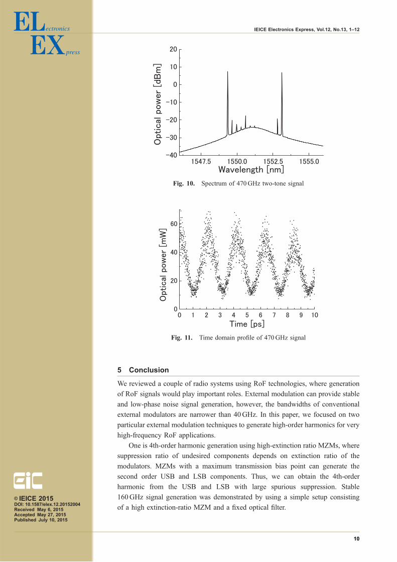
locked spectral components. As shown in Fig. 10, undesired components were
highly suppressed. The frequency separation between the fourth USB and the
eighth LSB was 468.84GHz. We measured a time domain profile of the high-speed
optical clock signal by using an optical sampling oscilloscope (ANDO AQ7750),
where the period of the signal was 2.13 ps, as shown in Fig. 11.
Fig. 8. Experimental setup for 470GHz signal generation
Fig. 9. Modulator output spectrum
© IEICE 2015DOI: 10.1587/elex.12.20152004Received May 6, 2015Accepted May 27, 2015Published July 10, 2015
9
IEICE Electronics Express, Vol.12, No.13, 1–12
5 Conclusion
We reviewed a couple of radio systems using RoF technologies, where generation
of RoF signals would play important roles. External modulation can provide stable
and low-phase noise signal generation, however, the bandwidths of conventional
external modulators are narrower than 40GHz. In this paper, we focused on two
particular external modulation techniques to generate high-order harmonics for very
high-frequency RoF applications.
One is 4th-order harmonic generation using high-extinction ratio MZMs, where
suppression ratio of undesired components depends on extinction ratio of the
modulators. MZMs with a maximum transmission bias point can generate the
second order USB and LSB components. Thus, we can obtain the 4th-order
harmonic from the USB and LSB with large spurious suppression. Stable
160GHz signal generation was demonstrated by using a simple setup consisting
of a high extinction-ratio MZM and a fixed optical filter.
Fig. 10. Spectrum of 470GHz two-tone signal
Fig. 11. Time domain profile of 470GHz signal
© IEICE 2015DOI: 10.1587/elex.12.20152004Received May 6, 2015Accepted May 27, 2015Published July 10, 2015
10
IEICE Electronics Express, Vol.12, No.13, 1–12

The other is high-order harmonic generation using ROMs. A 470GHz optical
clock signal was effectively generated from a 39GHz signal, where the sideband
components were stationary phase-locked each other without using feedback loop
control. We can expect that a stable and robust low phase-noise sub-THz signal can
be generated by feeding the optical output to a high-speed photodetector, so that
this technique would be also useful for sensing and broad-band communications in
sub-THz wave band.
Acknowledgments
We would like to acknowledge the support of Mr. J. Ichikawa, Mr. S. Oikawa and
Mr. K. Higuma of Sumitomo Osaka Cement and Mr. K. Yoshiara and Y. Shimakura
of Mitsubishi Electric. A part of this article is based on research outcomes of the
research project “R&D of high-precision imaging technology using 90GHz band
linear cells,” supported by the Japanese Government funding for “R&D to Expand
Radio Frequency Resources” from the Ministry of Internal Affairs and Communi-
cations.
Tetsuya Kawanishireceived the B.E., M.E., and Ph.D. degrees in electronics from Kyoto University,Kyoto, Japan, in 1992, 1994, and 1997, respectively.From 1994 to 1995, he was with the Production Engineering Laboratory,Matsushita Electric Industrial (Panasonic) Company, Ltd. In 1997, he was withVenture Business Laboratory of Kyoto University, where he was engaged inresearch on electromagnetic scattering and on near-field optics. He joined theCommunications Research Laboratory, Ministry of Posts and Telecommunica-tions (now the National Institute of Information and Communications Technol-ogy, NICT), Koganei, Tokyo, Japan, in 1998. In 2004, he was a Visiting Scholarwith the Department of Electrical and Computer Engineering, University ofCalifornia, San Diego, USA. In 2015, he joined Waseda University as a Professorof Department of Electronic and Physical Systems, and is working on high-speedoptical modulators and on RF photonics. He is a fellow of IEEE.
Takahide Sakamotowas born in Hyogo, Japan, in 1975. He received the B.S., M.S., and Ph.D.degrees in electronic engineering from the University of Tokyo, Tokyo, Japan, in1998, 2000, and 2003, respectively.Since 2003, he has been with the Communications Research Laboratory (nowNational Institute of Information and Communications Technology, NICT),Tokyo, Japan, where he is engaged in the area of optical-fiber communications.In 2010–2012, he was a Visiting Scholar with the Department of Electrical andComputer Engineering, University of California, Davis, supported by JapanSociety for the Promotion of Science. He is currently a Senior Researcher ofLightwave Devices Laboratory, Photonic Network Research Institute in NICT.His current research interests include fiber-optic devices and subsystems foroptical modulation/demodulation and signal processing.Dr. Sakamoto is a member of the IEEE Photonics Society and the Institute ofElectronics, Information and Communication Engineering (IEICE) of Japan.
© IEICE 2015DOI: 10.1587/elex.12.20152004Received May 6, 2015Accepted May 27, 2015Published July 10, 2015
11
IEICE Electronics Express, Vol.12, No.13, 1–12

Atsushi Kannoreceived B.S., M.S., and Ph.D. degree in science from the University of Tsukuba,Japan, in 1999, 2001, and 2005, respectively. In 2005, he was with the VentureBusiness Laboratory of the Institute of Science and Engineering, Universityof Tsukuba. In 2006, he joined the National Institute of Information andCommunications Technology Japan. His research interests are microwave/millimeter-wave/terahertz photonics, ultrafast optical communication systems,and lithium niobate optical modulators. Dr. Kanno is a member of the Institute ofElectronics, Information and Communication Engineers (IEICE), the JapanSociety of Applied Physics (JSAP), and the Institute of Electrical and ElectronicEngineers (IEEE).
© IEICE 2015DOI: 10.1587/elex.12.20152004Received May 6, 2015Accepted May 27, 2015Published July 10, 2015
12
IEICE Electronics Express, Vol.12, No.13, 1–12