sub-expression elimination logic expressions: –performed by logic optimization. –kernel-based...
TRANSCRIPT

Sub-expression elimination
• Logic expressions:– Performed by logic optimization.– Kernel-based methods.
• Arithmetic expressions:– Search isomorphic patterns in the parse trees.– Example:– a= x+ y; b = a+ 1; c = x+ y;– a= x+ y; b = a+ 1; c = a;

Examples of other transformations
• Dead-code elimination:– a= x; b = x+ 1; c = 2 * x;– a= x; can be removed if not referenced.
• Operator-strength reduction:– a= x2 ; b = 3 * x;– a= x * x; t = x<<1; b = x+ t;
• Code motion:– for ( i = 1; i < a * b) { } – t = a * b; for ( i = 1; i < t) { }

Strength reduction
++
*
**
B
X
XX
A
+*+
+* +++
+
X
A
X B
X 2 + AX + B X(X + A) + B
X
A
+* +
+*
*X
X
X
C
*++* +++ +
X B
+*
BX
X
A

Strength Reduction

Control- flow based transformations
• Model expansion.– Expand subroutine flatten
hierarchy.– Useful to expand scope of other
optimization techniques.– Problematic when routine is
called more than once.– Example:– x= a+ b; y= a * b; z = foo( x, y) ;– foo( p, q) {t =q-p; return(t);} – By expanding foo:– x= a+ b; y= a * b; z = y-x;
• Conditional expansion • Transform conditional into parallel execution with test at the end.• Useful when test depends on late signals.• May preclude hardware sharing.• Always useful for logic expressions.• Example:•y= ab; if ( a) x= b+d; else x= bd; can be expanded to: x= a( b+ d) + a’bd;•y= ab; x= y+ d( a+ b);

Pipelining

Associativity Transformation

FIR Parallelization
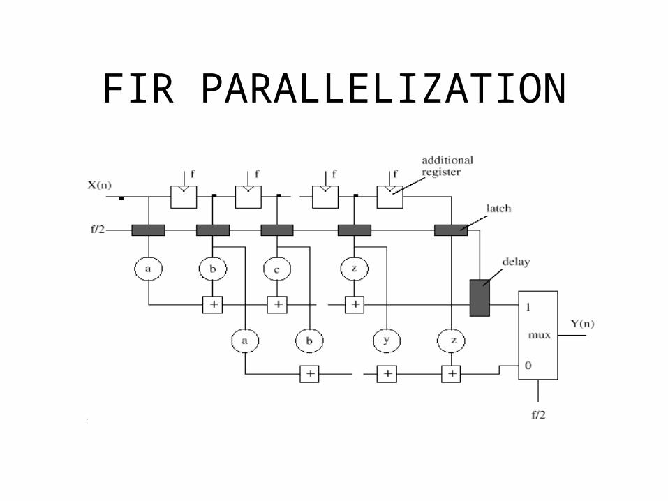
FIR PARALLELIZATION

FIR Filter Parallelization

FIR parallelization: two working phases

IIR filter recursive function
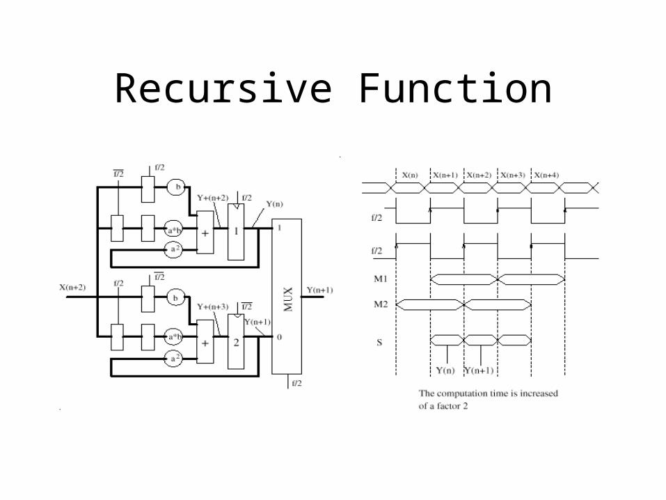
Recursive Function
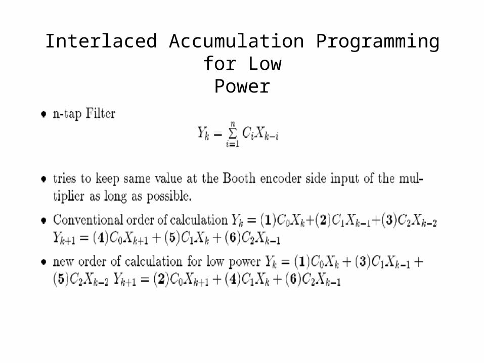
Interlaced Accumulation Programming for LowPower

4. Register Transfer Level Design

FIR3 Block Diagram and Flow Graph

High-Level Power Estimation
• Pcore = PDP + PMEM + PCNTR + PPROC
• PDP = PREG +PMUX +PFU + +PFU, where PREG is the power of the registers
• PMUX is the power of multiplexers• PFU is the power of functional units• PINT is the power of physical interconnet capacitance
(HYPER). tsinterconne physical ofnumber
theof estimatean is N and chip theof ecapacitanc estimated
total theis y),probabilitn transitiosignal averagean
by multiplied accessesct interconne ofnumber total(the
activity average theis where,/int
total
total
C
NCC
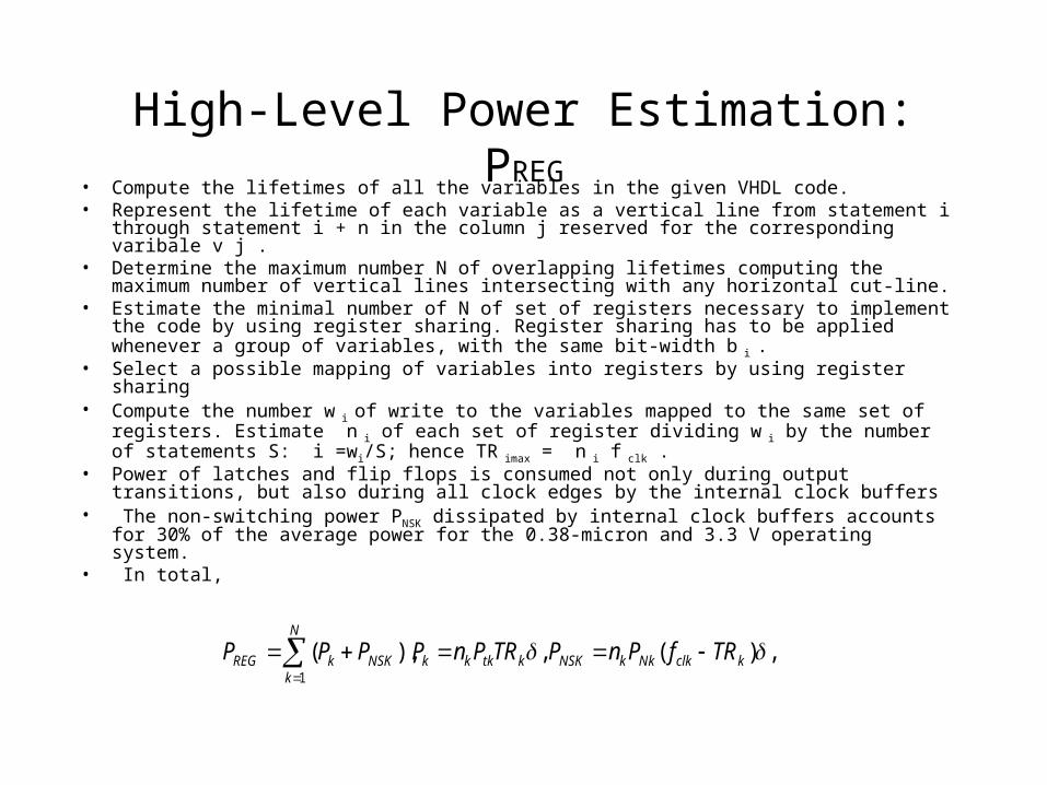
High-Level Power Estimation: PREG
• Compute the lifetimes of all the variables in the given VHDL code.• Represent the lifetime of each variable as a vertical line from statement i through
statement i + n in the column j reserved for the corresponding varibale v j .• Determine the maximum number N of overlapping lifetimes computing the
maximum number of vertical lines intersecting with any horizontal cut-line.• Estimate the minimal number of N of set of registers necessary to implement the
code by using register sharing. Register sharing has to be applied whenever a group of variables, with the same bit-width b i .
• Select a possible mapping of variables into registers by using register sharing• Compute the number w i of write to the variables mapped to the same set of
registers. Estimate n i of each set of register dividing w i by the number of statements S: i =wi/S; hence TR imax = n i f clk .
• Power of latches and flip flops is consumed not only during output transitions, but also during all clock edges by the internal clock buffers
• The non-switching power PNSK dissipated by internal clock buffers accounts for 30% of the average power for the 0.38-micron and 3.3 V operating system.
• In total,
,)(,),(1
kclkNkkNSKktkkkNSK
N
kkREG TRfPnPTRPnPPPP

PCNTR• After scheduling, the control is defined and optimized by the hardware mapper and
further by the logic synthesis process before mapping to layout.
• Like interconnect, therefore, the control needs to be estimated statistically.
• Global control model:
states. ofnumber
on thedependent strongly is ns transitioofnumber totalThe
22.1fF. is and 4.9fF is gy, technolo1.2 aFor
,
21
21
statesFSM NC
Local control model: the local controller account for a larger percentage of the total capacitance than the global controller.
.55.0,3.8,15.0,72 tech.,1.2 aFor
,
3,2,1,0,
3210
fstatestranslc BNNC
Where Ntrans is the number of tansitions, nstates is the number of states, Bf is the bus factor, and Clc is the capacitance switched in any local controller in one sample period. Bf is the ratio of the number of bus accesses to the number of busses.

Ntrans
• The number of transitions depends on assignment, scheduling, optimizations, logic
• optimization, the standard cell library used, the amount of glitchings and the statistics of the inputs.
.0.2,2.7,7.178 tech.1.2 aFor units.execution
ofnumber totalfor the estimatean is andCDFG the
in nodes and edges ofnumber theare and period,
sampleper cycles control ofnumber theis S s,controller loal the
of outputs on the ns transitioofnumber theis where
)()(
321
321
Exu
nodesedges
trans
Exuedgesnodestrans
N
NN
N
NSNNN

Behavioral Synthesis• loop unrolling : localize the data to reduce the activity of the inputs of the
functional units or two output samples are computed in parallel based on two input samples.
Neither the capacitance switched nor the voltage is altered. However, loop unrolling enables several other transformations (distributivity, constant propagation, and pipelining). After distributivity and constant propagation,
The transformation yields critical path of 3, thus voltage can be dropped.• Clock Selection : Choose optimal system clock period Eliminate slacks/improve resource
utilization and Enable greater voltage scaling• Module selection : For each operation, choose library template• Flow graph restructuring : pull out operations on the critical cycle.
)( 211
211
nnnnnn
nnn
YAXAXYAXY
YAXY
22
1
211
nnnn
nnn
YAYAXY
YAXY

High-Level Power Estimation: PMUX and PFU
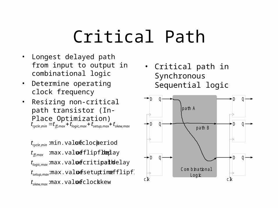
Critical Path• Longest delayed path from input to
output in combinational logic
• Determine operating clock frequency
• Resizing non-critical path transistor (In-Place Optimization)
• Critical path in Synchronous Sequential logic
skewclock of max.value :
flipflop of timesetup of max.value :
delaypath critical of max.value :
delay flipflop of max.value :
periodclock of min.value :,
,
skew,max
setup,max
logic,max
ff,max
mincycle
skew,maxsetup,maxlogic,maxff,maxmincycle
t
t
t
t
t
ttttt
D Q
D Q
D Q
D Q
D Q
D Q
c lk c lk
C ombinationalLogic
path A
path B

Loop Unrolling for Low Power
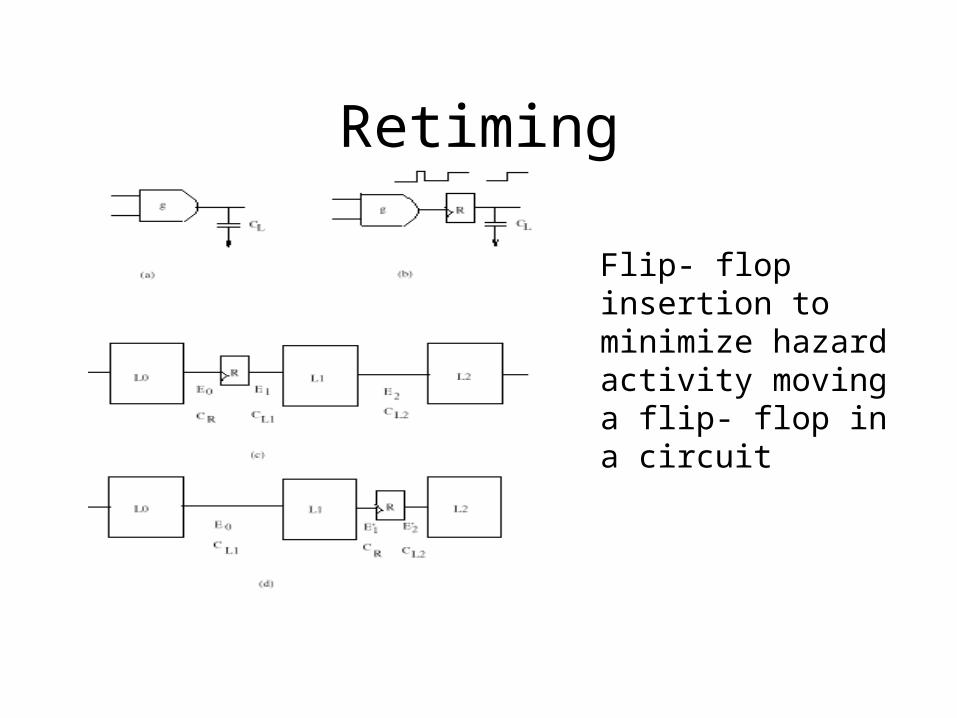
Retiming
Flip- flop insertion to minimize hazard activity moving a flip- flop in a circuit

Exploiting spatial locality for interconnect power reduction
Global
Local
Adder1
Adder2

Balancing maximal time-sharing and fully-parallel implementation
A fourth-order parallel-form
IIR filter
(a) Local assignment
(2 global transfers), (b) Non-local assignment
(20 global transfers)
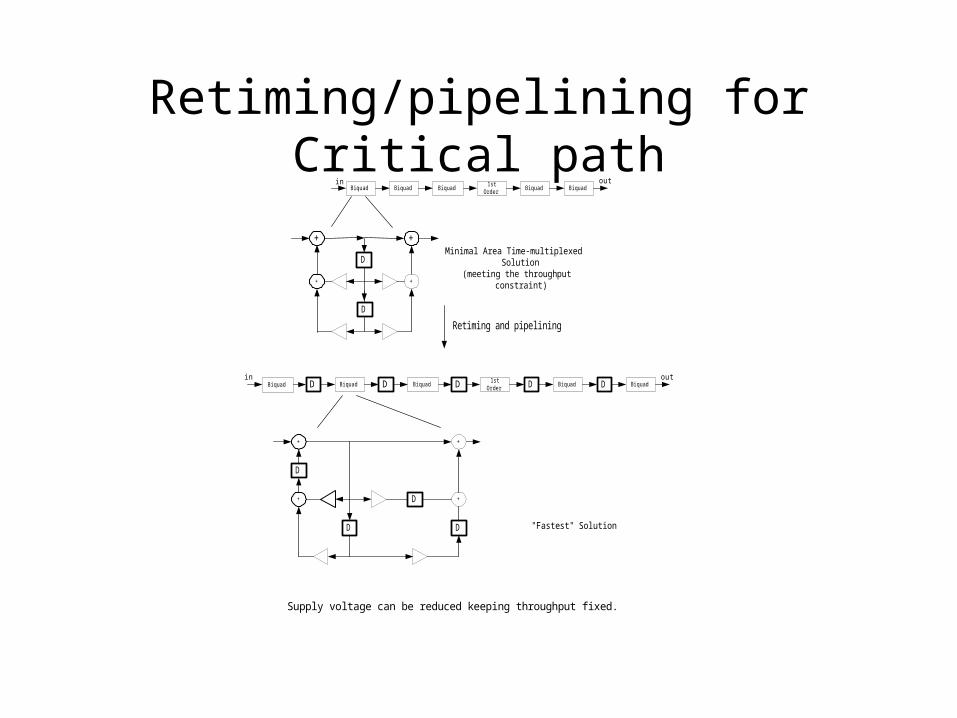
Retiming/pipelining for Critical path
+ +
+
D
D
+
Biquad Biquad Biquad1st
OrderBiquad Biquad
in out
Minimal Area Time-multiplexed Solution
(meeting the throughput constraint)
Retiming and pipelining
Biquad Biquad Biquad1st
OrderBiquad Biquad
in outD DDDD
+
++
+
DD
D
D
"Fastest" Solution
Supply voltage can be reduced keeping throughput fixed.