study on the load distribution and dynamic characteristics
TRANSCRIPT

applied sciences
Article
Study on the Load Distribution and DynamicCharacteristics of a Thin-Walled IntegratedSquirrel-Cage Supporting Roller Bearing
Yuze Mao, Liqin Wang * and Chuanwei ZhangSchool of Mechatronics Engineering, Harbin Institute of Technology, Harbin 150001, China;[email protected] (Y.M.); [email protected] (C.Z.)* Correspondence: [email protected]; Tel.: +86-451-8640-2012
Academic Editor: Zhong TaoReceived: 7 October 2016; Accepted: 3 December 2016; Published: 14 December 2016
Abstract: Thin-walled integrated flexible support structures are the major trend in the developmentof current rolling bearing technology. A thin-walled, integrated, squirrel-cage flexible support rollerbearing, quasi-dynamic iterative finite element analysis (FEA) model is established in this paper.The FEA model is used to calculate the structural deformation of the thin-wall rings and supportstructures; the dynamic characteristics of the bearing are analyzed using the noncircular bearingmodified quasi-dynamic model. The influence of the integrated flexible support structure onthe internal load distribution and the dynamic characteristics of the roller bearing are analyzed.The results indicate that with the support of a flexible squirrel-cage, the maximum contact load isdecreased by 14.2%, the loading region is enlarged by 25%, the cage slide ratio is reduced by 24%,and the fatigue life is increased by more than 50%. In addition, as the ring wall thickness increased,the results increasingly approached those under a rigid assumption.
Keywords: rolling bearing; thin wall; flexible support; structural deformation; load distribution;fatigue life
1. Introduction
Advanced rolling bearing technology is one of the basic strategic industries and core technologiesin high-speed systems and the aerospace field. The use of thin walls, lightweight structures, andcomponent integration represent major trends in the development of advanced rolling bearingtechnologies [1]. As a main technological trend in the field of high-speed bearings, the integratedsquirrel-cage flexible support roller bearing is a thin-wall bearing with a squirrel-cage structureconnected to the outer ring and a hollow shaft assembled in the inner ring. In this type of structure,the hollow shaft, bearing ring, and squirrel-cage flexible support structures are all thin-walled, and,as a result, easily produce elastic structural deformations under load; this induces a change in theinternal load distribution of the bearing, and leads to a significant influence on the characteristics ofthe bearing dynamics, which should not be neglected.
Based on the Hertz theoretical calculation model, Jones [2] built a static model and calculatedthe load distribution of rolling bearing. Subsequently, many researchers studied the behaviors ofrolling bearings [2–5], however, most of their methods are built using the rigid structure hypothesis,considering the rings as constant geometry parts, and ignoring the elastic deformations of the structuresunder load. Thus, these rigid structure assumption models cannot fully meet the demands of thecontinued development of rolling bearings, because the structural deformation of thin-walled ringsand flexible supports is much more pronounced. Thus, it is essential to carry out dynamic performanceanalyses of the integrated squirrel-cage flexible support bearing in the study of current high-endbearing usage.
Appl. Sci. 2016, 6, 415; doi:10.3390/app6120415 www.mdpi.com/journal/applsci

Appl. Sci. 2016, 6, 415 2 of 11
Broschard [6] established a flexible bearing model for planetary gear, while Shen [7] built a flexiblebearing model for harmonic gear. However, these two models are only for bearings in planetarygear transmission or harmonic gear transmission, which are quite different from the flexible supportbearings in high-speed shaft systems. Lostado [8] analyzed the contact stress of the double-row taperedroller bearings using the finite element method; experimental analyses and an analytical model showsthat the finite element method could be very accurate in bearing stress calculations. Yao [9] used thecurved Timoshenko beam (CTB) theory to calculate the structural deformation of a thin-walled bearingring, and analyzed the load distribution of thin-walled roller bearing; however, the model, assumedthat the rings are supported at one or two azimuth positions only, and did not consider the specificform of the bearing support. Researchers, such as Ignacio [10], Kania [11], Olave [12], Shu Ju [13] andLiu [14], used the finite element method to analyze the structural deformation of thin-walled rings,but such a method cannot take into account the contact mechanics and the lubrication status betweenthe rollers and the raceway. Moreover, a method in which linear springs are used to replace rollingelements cannot provide an accurate internal loading solution, because the load-deflection factor isnon-linear, and the centrifugal effort in high-speed bearing is very difficult to simulate by a springelement, and it would be very complicated when the bearing has clearances because the number ofloading rollers is unknown [15]; thus, it was difficult to precisely analyze the dynamic performance ofthe bearing.
In this paper, an integrated squirrel-cage flexible support roller bearing iterative quasi-dynamicfinite element analysis (FEA) model is established. This model is used to comprehensively consider theeffects of contact mechanics, lubrication, and structural deformations. The model can accuratelypredict the dynamic performance of the integrated squirrel-cage flexible support roller bearing.The standard circular rolling bearing quasi-dynamic model is modified in order to obtain the modifiednoncircular rolling bearing quasi-dynamic model. The integrated squirrel-cage flexible support rollerbearing finite element model is constructed using ANSYS software (ANSYS 12.0, ANSYS Corporation,Canonsburg, PA, USA), and is used to calculate the deformation of the bearing ring and squirrel-cagestructure. The calculated deformations are inserted into the noncircular rolling bearing quasi-dynamicmodified model in order to obtain load distribution and dynamic characteristic analysis results ofthe bearing.
2. Model Design
2.1. Modified Noncircular Rolling Bearing Quasi-Dynamic Model
Quasi-dynamic analysis is an accurate bearing analysis method, because it comprehensivelyconsiders the microscopic contact and the rheological characteristics of the lubricant. Quasi-dynamicanalysis can accurately calculate the dynamic characteristics of a rigid rolling bearing, but is not suitedfor a flexible bearing, of which the raceways would be noncircular following structural deformation;thus, a modified quasi-dynamic model for noncircular rolling bearings is needed.
Figure 1 shows a sketch of the force of roller bearing. Cutting the roller into slices, the k-th slice ofthe j-th roller experiences contact forces Q1jk and Q2jk, and drags forces T1jk and T2jk from the innerand outer raceways through oil films, normal force Fcj and tangential force fcj from the cage, andoil–gas mixture frictional force Fgj, as well as its own inertial force, Fzj, and inertia moment Mxj dueto rolling.

Appl. Sci. 2016, 6, 415 3 of 11Appl. Sci. 2016, 6, 415 3 of 12
oj
zj
yj
xj
o2
z2
y2
x2
oz
yx
k-th slice
Inner ring
j-th roller
ro2ojro2pj2
rp'2p2p'2p2
Ck
oj
zj
yj
xj
My
j Fcj
Fgj
fcjQ2j
k
Q1j
k
P2j
k
P1j
k
T2jk
T1jk
Fzj
Mx
j
ωxj
(a) (b)
Figure 1. Sketch of the force of roller bearing: (a) Model of the roller–raceway interaction; (b) forces
and moments acting on a roller.
According to the Hertz theory, forces 1jk
Q and 2jk
Q between the roller slice and the raceways
can be obtained from contact approaches 1
δjk and 2
δjk of the slice and raceways, respectively.
When the ring deforms, the raceway becomes a nonideal cylindrical surface. The deviations of the
k‐th slice of the j‐th roller at the local surface from the ideal cylindrical surface can be expressed as
1δ
jkh and
2δ
jkh. These two deviations can be superimposed with approaches
1δ
jk and
2δ
jk, based
on the small deformation assumption. By further considering oil film thickness 1jkh
and 2jkh
at
the contact area, the actual contact approaches, '
1δ
jk and '
2δ
jk , between the roller slice and the
noncircular raceway can be obtained. Thus, contact loads '
1jkQ
and '
2jkQ
of the rolling object and
the noncircular raceway can be obtained, as expressed in Equation (1). k
C is the correction of the
roller radius, considering the Roller Profile Modification and chamfer [16]. In addition, the roller
balance equation can be established as Equation (2). The lubricant parameters in the model are
calculated using the Hertz contact theory, the Dowson‐Higginson formula [17], and the five‐parameter
rheological model [18]. The five‐parameter rheological model has been experimentally verified and
contains the viscosity–pressure property and the viscosity–temperature property of the oil.
'
1 1 1 1
1/0.9' 0.8
' 1 11 2
1
'
2 2 2 2
1/0.9' 0.8
' 2 22 2
2
22 0.5
δ δ δ
δ π
3.81 2(1 υ)
δ δ δ
δ πQ
3.81 2(1 υ)
0; ( 0.5)2 2
( )4
jk jk jk jkh k
jk ejk
jk jk jk jkh k
jk ejk
e s e e s
k
s
h C
l EQ
h C
l E
l l l l lk
nC
lR
2 2 0.5( ) ;0
2 2e s e s
k e
l l l lR x k k l
(1)
Figure 1. Sketch of the force of roller bearing: (a) Model of the roller–raceway interaction; (b) forcesand moments acting on a roller.
According to the Hertz theory, forces Q1jk and Q2jk between the roller slice and the raceways canbe obtained from contact approaches δ1jk and δ2jk of the slice and raceways, respectively. When thering deforms, the raceway becomes a nonideal cylindrical surface. The deviations of the k-th sliceof the j-th roller at the local surface from the ideal cylindrical surface can be expressed as δ1jkh andδ2jkh. These two deviations can be superimposed with approaches δ1jk and δ2jk, based on the smalldeformation assumption. By further considering oil film thickness h1jk and h2jk at the contact area,the actual contact approaches, δ′1jk and δ′2jk, between the roller slice and the noncircular raceway canbe obtained. Thus, contact loads Q′1jk and Q′2jk of the rolling object and the noncircular raceway can beobtained, as expressed in Equation (1). Ck is the correction of the roller radius, considering the RollerProfile Modification and chamfer [16]. In addition, the roller balance equation can be established asEquation (2). The lubricant parameters in the model are calculated using the Hertz contact theory, theDowson-Higginson formula [17], and the five-parameter rheological model [18]. The five-parameterrheological model has been experimentally verified and contains the viscosity–pressure property andthe viscosity–temperature property of the oil.
δ′1jk = δ1jk + h1jk + δ1jkh + Ck
Q′1jk =
(δ′1jk ·l0.8
e3.81
)1/0.9·(
π·E12(1−υ2
1)
)δ′2jk = δ2jk + h2jk + δ2jkh + Ck
Q′2jk =
(δ′2jk ·l0.8
e3.81
)1/0.9·(
π·E22(1−υ2
2)
)Ck =
{0; le−ls
2 ≤ (k− 0.5) · len ≤
le+ls2
(R2 − l2s4 )
0.5− (R2 − x2
k)0.5; 0 < k < le−ls
2 ∪ le+ls2 < k < le
(1)
1n
n∑
k=1(T1jk − T2jk + P1jk − P2jk) + Fcj + Fgj + Fyj = 0
1n
n∑
k=1(−Q′1jk + Q′2jk)− fcj + Fzj = 0
Dw2 ( 1
n
n∑
k=1(T1jk + T2jk)− fcj) + Mxj = 0
1n
n∑
k=1(−Q′1jkxk + Q′2jkxk) + Myj = 0
1n
n∑
k=1(−P1jkxk + P2jkxk) + Mzj = 0
(2)

Appl. Sci. 2016, 6, 415 4 of 11
Variable δ1jkh and δ2jkh can be obtained based on the geometric shape of the deformed raceways,thus, with the rollers’ loads on the inner ring and the applied load of the ring from the shaft, the ringbalance equation can be obtained, as expressed in Equation (3). The cage balance equation can beobtained using the method of Cui [16]. Thus, the modified noncircular ring bearing quasi-dynamicmodel is established.
Fy − Flrsinψ− Fltcosψ−N∑
j=1v
n∑
k=1
Q′2jkle
sin φj = 0
Fz − Flrcosψ− Fltsinψ−N∑
j=1v
n∑
k=1
Q′2jkle
cos φj = 0
My −N∑
j=1
(v
n∑
k=1
Q′2jkle
)·
n∑
k=1Q′2jk ·[(k−0.5)v−0.5le ]
n∑
k=1Q′2jk
· cos φj = 0
Mz −N∑
j=1
(v
n∑
k=1
Q′2jkle
)·
n∑
k=1Q′2jk ·[(k−0.5)v−0.5le ]
n∑
k=1Q′2jk
· sin φj = 0
Mx − Dm2
N∑
j=1
(v
n∑
k=1(T2jk + P2jk)
)= 0
(3)
The proposed model can be used to accurately analyze the load distribution and dynamiccharacteristics of the deformed bearing by taking into consideration the influence of the noncircularraceway following structural deformation, and also the microscopic contact and the rheologicallubricant properties in the bearing. By setting the values of δ1jkh and δ2jkh as zero, this model can alsoanalyze load distribution without structural deformations, which can be the initial values of finiteelement analysis.
2.2. Finite Element Analysis of Integrated Squirrel-Cage Structural Deformation
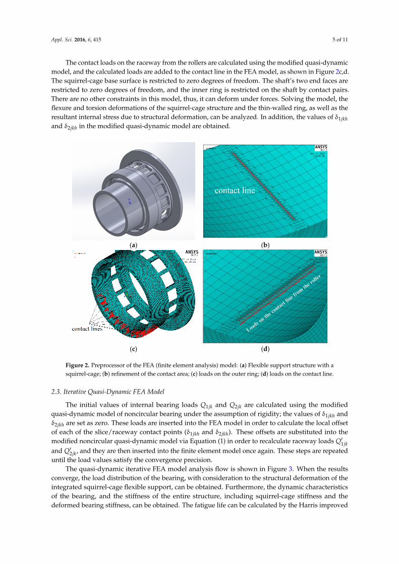
An integrated squirrel-cage flexible support roller bearing includes a roller bearing, a hollowshaft, and a squirrel-cage support structure, and all components are thin-walled, as shown in Figure 2a.The shaft is assembled in the inner ring. The outer ring and the squirrel-cage structure are oneintegrated component, which means the outer ring is a part of the squirrel-cage structure, and theouter raceway is manufactured on the internal surface of the cylinder of the squirrel-cage structure.A finite element model containing a thin-walled hollow shaft, an inner bearing ring, and an outerring-squirrel-cage support structure was constructed in ANSYS.
Boolean operation of the assembly was conducted in order to ensure satisfaction of the hexahedralmeshing conditions, and three-dimensional object element meshing is achieved with SOLID45 elements.The mesh size has a great influence on the accuracy of the calculation [19]. The dimensions of contactareas are on the micrometer scale and the overall dimension of the bearing is in the millimeter scale.Thus, after meshing the whole assembly, the contact lines on the inner and outer raceway is re-mashedtwice with smaller mesh sizes, so it is more accurate in imposing a load, as shown in Figure 2b.
To accurately reflect the relationship between the inner ring and the shaft, contact pairs are placedbetween the inner surface of the inner ring and the outer surface of the shaft, and between the sideof the inner ring and the shaft shoulder. The contact method is surface-to-surface, and the frictioncoefficient is 0.1 [13]. The outer ring and the squirrel-cage structure are one integrated component,thus there is no contact pair. Designating the inner surface and the side surface of the inner ring as thecontacting surface and the corresponding shaft outer surface and shaft shoulder as the target surface,respectively, the mutual contacting portion is described by TARGE170 and CONTA174 surface–surfacecontact elements. Targe170 is used to represent various 3-D “target” surfaces for the associated contactelements, and CONTA174 is used to represent contact and sliding between 3-D “target” surfaces and adeformable surface defined by this element.
Appl. Sci. 2016, 6, 415 5 of 11
The contact loads on the raceway from the rollers are calculated using the modified quasi-dynamicmodel, and the calculated loads are added to the contact line in the FEA model, as shown in Figure 2c,d.The squirrel-cage base surface is restricted to zero degrees of freedom. The shaft’s two end faces arerestricted to zero degrees of freedom, and the inner ring is restricted on the shaft by contact pairs.There are no other constraints in this model, thus, it can deform under forces. Solving the model, theflexure and torsion deformations of the squirrel-cage structure and the thin-walled ring, as well as theresultant internal stress due to structural deformation, can be analyzed. In addition, the values of δ1jkhand δ2jkh in the modified quasi-dynamic model are obtained.
Appl. Sci. 2016, 6, 415 5 of 12
SOLID45 elements. The mesh size has a great influence on the accuracy of the calculation [19]. The dimensions of contact areas are on the micrometer scale and the overall dimension of the bearing is in the millimeter scale. Thus, after meshing the whole assembly, the contact lines on the inner and outer raceway is re-mashed twice with smaller mesh sizes, so it is more accurate in imposing a load, as shown in Figure 2b.
To accurately reflect the relationship between the inner ring and the shaft, contact pairs are placed between the inner surface of the inner ring and the outer surface of the shaft, and between the side of the inner ring and the shaft shoulder. The contact method is surface-to-surface, and the friction coefficient is 0.1 [13]. The outer ring and the squirrel-cage structure are one integrated component, thus there is no contact pair. Designating the inner surface and the side surface of the inner ring as the contacting surface and the corresponding shaft outer surface and shaft shoulder as the target surface, respectively, the mutual contacting portion is described by TARGE170 and CONTA174 surface–surface contact elements.Targe170 is used to represent various 3-D “target” surfaces for the associated contact elements, and CONTA174 is used to represent contact and sliding between 3-D target surfaces and a deformable surface defined by this element.
The contact loads on the raceway from the rollers are calculated using the modified quasi-dynamic model, and the calculated loads are added to the contact line in the FEA model, as shown in Figure 2c,d. The squirrel-cage base surface is restricted to zero degrees of freedom. The shaft’s two end faces are restricted to zero degrees of freedom, and the inner ring is restricted on the shaft by contact pairs. There are no other constraints in this model, thus, it can deform under forces. Solving the model, the flexure and torsion deformations of the squirrel-cage structure and the thin-walled ring, as well as the resultant internal stress due to structural deformation, can be analyzed. In
addition, the values of 1
δjkh and
2δ
jkh in the modified quasi-dynamic model are obtained.
(a) (b)
(c) (d)
Figure 2. Preprocessor of the FEA (finite element analysis) model: (a) Flexible support structure with a squirrel-cage; (b) refinement of the contact area; (c) loads on the outer ring; (d) loads on the contact line.
2.3. Iterative Quasi-Dynamic FEA Model
Figure 2. Preprocessor of the FEA (finite element analysis) model: (a) Flexible support structure with asquirrel-cage; (b) refinement of the contact area; (c) loads on the outer ring; (d) loads on the contact line.
2.3. Iterative Quasi-Dynamic FEA Model
The initial values of internal bearing loads Q1jk and Q2jk are calculated using the modifiedquasi-dynamic model of noncircular bearing under the assumption of rigidity; the values of δ1jkh andδ2jkh are set as zero. These loads are inserted into the FEA model in order to calculate the local offsetof each of the slice/raceway contact points (δ1jkh and δ2jkh). These offsets are substituted into themodified noncircular quasi-dynamic model via Equation (1) in order to recalculate raceway loads Q′1jkand Q′2jk, and they are then inserted into the finite element model once again. These steps are repeateduntil the load values satisfy the convergence precision.
The quasi-dynamic iterative FEA model analysis flow is shown in Figure 3. When the resultsconverge, the load distribution of the bearing, with consideration to the structural deformation of theintegrated squirrel-cage flexible support, can be obtained. Furthermore, the dynamic characteristicsof the bearing, and the stiffness of the entire structure, including squirrel-cage stiffness and thedeformed bearing stiffness, can be obtained. The fatigue life can be calculated by the Harris improved

Appl. Sci. 2016, 6, 415 6 of 11
Lundberg-Palmgren (L-P) theory. The Harris improved L-P theory is based on the L-P theory andcontains the load distribution and lubrication of the bearing [2].
Appl. Sci. 2016, 6, 415 6 of 12
2.3. Iterative Quasi‐Dynamic FEA Model
The initial values of internal bearing loads 1jkQ
and 2jkQ
are calculated using the modified
quasi‐dynamic model of noncircular bearing under the assumption of rigidity; the values of 1
δjkh
and 2
δjkh are set as zero. These loads are inserted into the FEA model in order to calculate the
local offset of each of the slice/raceway contact points (1
δjkh and 2
δjkh ). These offsets are
substituted into the modified noncircular quasi‐dynamic model via Equation (1) in order to
recalculate raceway loads '
1jkQ
and '
2jkQ
, and they are then inserted into the finite element model
once again. These steps are repeated until the load values satisfy the convergence precision.
The quasi‐dynamic iterative FEA model analysis flow is shown in Figure 3. When the results
converge, the load distribution of the bearing, with consideration to the structural deformation of
the integrated squirrel‐cage flexible support, can be obtained. Furthermore, the dynamic
characteristics of the bearing, and the stiffness of the entire structure, including squirrel‐cage
stiffness and the deformed bearing stiffness, can be obtained. The fatigue life can be calculated by
the Harris improved Lundberg‐Palmgren (L‐P) theory. The Harris improved L‐P theory is based on
the L‐P theory and contains the load distribution and lubrication of the bearing [2].
Start
Initial loads between rollers
and rings
FEA model analysis
Modified quasi-dynamic model of non-circular race
Error of Qi and Q(i-1) <0.5%
YN
Deformation of squirrel and
Distortion of rings
Modified loads between rollers and
rings (Qi)
Quasi-dynamic of rigid assumption
i=i+1
Load distribution, sliding, fatigue life and stiffness
End
Figure 3. Flow diagram of the quasi‐dynamic iterative FEA model.
3. Results and Discussion
An integrated squirrel‐cage support roller bearing is used as an example to analyze the
influence of structural deformation on the load distribution, dynamic behavior, and fatigue life of
the bearing. The parameters of the bearing are given in Tables 1–3, and the numerical values of the
analysis results depend on the geometry of the bearing.
Figure 3. Flow diagram of the quasi-dynamic iterative FEA model.
3. Results and Discussion
An integrated squirrel-cage support roller bearing is used as an example to analyze the influenceof structural deformation on the load distribution, dynamic behavior, and fatigue life of the bearing.The parameters of the bearing are given in Tables 1–3, and the numerical values of the analysis resultsdepend on the geometry of the bearing.
Table 1. Geometry parameters and working conditions of the bearing.
Parameter Value/mm Parameter Value
Inner ring 59.6 inner ring thickness (mm) 5Outer ring 82.2 outer ring thickness (mm) 3.6
Roller quantity 30 length of squirrel-cage (mm) 10.25Roller diameter 5 shift thickness (mm) 4
Roller length 5 radial load (N) 19,621.1clearance 0.05 Speed (r/min) 38,000
Table 2. Material parameters of the bearing and squirrel-structure.
Component Elastic Modulus(E)/GPa
Poisson Ratio (υ) Density(ρ)/kg/m3
Thermal ExpansionCoefficient (α)
Shaft 179 0.281 8240 0.0138Inner ring 203 0.28 7850 0.0112
Roller 209 0.3 7860 0.0119Outer ring-squirrel Cage 203 0.28 7850 0.0112
Appl. Sci. 2016, 6, 415 7 of 11
Table 3. Temperature of bearing components.
Shaft Inner Ring Roller Outer Ring and Squirrel-Cage
230 ◦C 220 ◦C 226 ◦C 218 ◦C
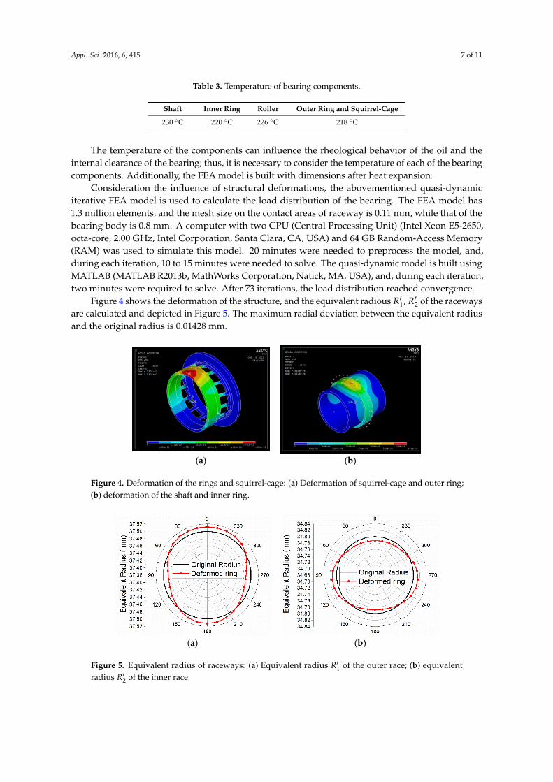
The temperature of the components can influence the rheological behavior of the oil and theinternal clearance of the bearing; thus, it is necessary to consider the temperature of each of the bearingcomponents. Additionally, the FEA model is built with dimensions after heat expansion.
Consideration the influence of structural deformations, the abovementioned quasi-dynamiciterative FEA model is used to calculate the load distribution of the bearing. The FEA model has1.3 million elements, and the mesh size on the contact areas of raceway is 0.11 mm, while that of thebearing body is 0.8 mm. A computer with two CPU (Central Processing Unit) (Intel Xeon E5-2650,octa-core, 2.00 GHz, Intel Corporation, Santa Clara, CA, USA) and 64 GB Random-Access Memory(RAM) was used to simulate this model. 20 minutes were needed to preprocess the model, and,during each iteration, 10 to 15 minutes were needed to solve. The quasi-dynamic model is built usingMATLAB (MATLAB R2013b, MathWorks Corporation, Natick, MA, USA), and, during each iteration,two minutes were required to solve. After 73 iterations, the load distribution reached convergence.
Figure 4 shows the deformation of the structure, and the equivalent radious R′1, R′2 of the racewaysare calculated and depicted in Figure 5. The maximum radial deviation between the equivalent radiusand the original radius is 0.01428 mm.
Appl. Sci. 2016, 6, 415 7 of 12
Table 1. Geometry parameters and working conditions of the bearing.
Parameter Value/mm Parameter Value
Inner ring 59.6 inner ring thickness (mm) 5
Outer ring 82.2 outer ring thickness (mm) 3.6
Roller quantity 30 length of squirrel‐cage (mm) 10.25
Roller diameter 5 shift thickness (mm) 4
Roller length 5 radial load (N) 19,621.1
clearance 0.05 Speed (r/min) 38,000
Table 2. Material parameters of the bearing and squirrel‐structure.
Component Elastic Modulus
(E)/GPa
Poisson Ratio
(υ)
Density
(ρ)/kg/m3
Thermal Expansion
Coefficient (α)
Shaft 179 0.281 8240 0.0138
Inner ring 203 0.28 7850 0.0112
Roller 209 0.3 7860 0.0119
Outer ring‐squirrel Cage 203 0.28 7850 0.0112
Table 3. Temperature of bearing components.
Shaft Inner Ring Roller Outer Ring and Squirrel‐Cage
230 °C 220 °C 226 °C 218 °C
The temperature of the components can influence the rheological behavior of the oil and the
internal clearance of the bearing; thus, it is necessary to consider the temperature of each of the
bearing components. Additionally, the FEA model is built with dimensions after heat expansion.
Consideration the influence of structural deformations, the abovementioned quasi‐dynamic
iterative FEA model is used to calculate the load distribution of the bearing. The FEA model has 1.3
million elements, and the mesh size on the contact areas of raceway is 0.11 mm, while that of the
bearing body is 0.8 mm. A computer with two CPU (Central Processing Unit) (Intel Xeon E5‐2650,
octa‐core, 2.00 GHz, Intel Corporation, Santa Clara, CA, USA) and 64 GB Random‐Access Memory
(RAM) was used to simulate this model. 20 minutes were needed to preprocess the model, and,
during each iteration, 10 to 15 minutes were needed to solve. The quasi‐dynamic model is built
using MATLAB (MATLAB R2013b, MathWorks Corporation, Natick, MA, USA), and, during each
iteration, two minutes were required to solve. After 73 iterations, the load distribution reached
convergence.
Figure 4 shows the deformation of the structure, and the equivalent radious '
1R
,'
2R of the
raceways are calculated and depicted in Figure 5. The maximum radial deviation between the
equivalent radius and the original radius is 0.01428 mm.
(a) (b)
Figure 4. Deformation of the rings and squirrel‐cage: (a) Deformation of squirrel‐cage and outer ring;
(b) deformation of the shaft and inner ring. Figure 4. Deformation of the rings and squirrel-cage: (a) Deformation of squirrel-cage and outer ring;(b) deformation of the shaft and inner ring.Appl. Sci. 2016, 6, 415 8 of 12
(a) (b)
Figure 5. Equivalent radius of raceways: (a) Equivalent radius '
1R of the outer race; (b) equivalent
radius '
2R of the inner race.
The calculated results are compared to those based on the rigidity assumption, without
consideration of the influence of the structural deformation. The load distribution of the bearing is
shown in Figure 6.
Figure 6. The contrast of load distribution between the rigid support and flexible support.
It can be seen from the above results that, compared to the results calculated under the rigid
support assumption, the maximum roller/raceway load decreased to 3035 N from 3537 N due to the
influence of the deformation of the flexible squirrel‐cage support structure, representing a decrease
of 14.2%. Moreover, the internal bearing load is distributed more evenly. The number of loaded
rollers decreased to 9 from 11, so the loading range is enlarged to 120° (−60°~60°) from 96°
(−48°~48°), representing an increase of 25%.
Because bearing sliding is strongly dependent on the roller/raceway load, the change in the load
distribution alters the bearing slide ratio. Compared to the rigid support, the bearing cage slide ratio
under the flexible support decreased from 6.28% to 4.77%, representing a decrease of 24.05%. Figure 7
shows the slide ratio distribution of each roller.
Figure 5. Equivalent radius of raceways: (a) Equivalent radius R′1 of the outer race; (b) equivalentradius R′2 of the inner race.

Appl. Sci. 2016, 6, 415 8 of 11
The calculated results are compared to those based on the rigidity assumption, withoutconsideration of the influence of the structural deformation. The load distribution of the bearingis shown in Figure 6.
Appl. Sci. 2016, 6, 415 8 of 12
(a) (b)
Figure 5. Equivalent radius of raceways: (a) Equivalent radius '
1R of the outer race; (b) equivalent
radius '
2R of the inner race.
The calculated results are compared to those based on the rigidity assumption, without
consideration of the influence of the structural deformation. The load distribution of the bearing is
shown in Figure 6.
Figure 6. The contrast of load distribution between the rigid support and flexible support.
It can be seen from the above results that, compared to the results calculated under the rigid
support assumption, the maximum roller/raceway load decreased to 3035 N from 3537 N due to the
influence of the deformation of the flexible squirrel‐cage support structure, representing a decrease
of 14.2%. Moreover, the internal bearing load is distributed more evenly. The number of loaded
rollers decreased to 9 from 11, so the loading range is enlarged to 120° (−60°~60°) from 96°
(−48°~48°), representing an increase of 25%.
Because bearing sliding is strongly dependent on the roller/raceway load, the change in the load
distribution alters the bearing slide ratio. Compared to the rigid support, the bearing cage slide ratio
under the flexible support decreased from 6.28% to 4.77%, representing a decrease of 24.05%. Figure 7
shows the slide ratio distribution of each roller.
Figure 6. The contrast of load distribution between the rigid support and flexible support.
It can be seen from the above results that, compared to the results calculated under the rigidsupport assumption, the maximum roller/raceway load decreased to 3035 N from 3537 N due to theinfluence of the deformation of the flexible squirrel-cage support structure, representing a decrease of14.2%. Moreover, the internal bearing load is distributed more evenly. The number of loaded rollersdecreased to 9 from 11, so the loading range is enlarged to 120◦ (−60◦~60◦) from 96◦ (−48◦~48◦),representing an increase of 25%.
Because bearing sliding is strongly dependent on the roller/raceway load, the change in the loaddistribution alters the bearing slide ratio. Compared to the rigid support, the bearing cage slide ratiounder the flexible support decreased from 6.28% to 4.77%, representing a decrease of 24.05%. Figure 7shows the slide ratio distribution of each roller.Appl. Sci. 2016, 6, 415 9 of 12
Figure 7. Slide ratio of rollers.
Figure 8 shows the changes observed for the bearing cage slide ratio due to variations in the
rotational speed. As the rotational speed increased, the cage sliding decreased by a greater
percentage.
Figure 8. Influence of operation speed on cage sliding.
Figure 9 shows the influence of the change in thickness of the outer ring on the load
distribution of the bearing. As the outer ring increases in thickness, the load distribution more
closely approached the calculation result obtained under the rigid assumption; conversely, as the
outer ring became thinner, the influence of structural deformation increased significantly.
Figure 9. Influence of ring thickness on load distribution.
Figure 10 shows the cage slide ratio due to different ring thicknesses. It can be seen that under
the rigid assumption, the ring wall thickness does not influence the cage sliding. After considering
Figure 7. Slide ratio of rollers.
Figure 8 shows the changes observed for the bearing cage slide ratio due to variations in therotational speed. As the rotational speed increased, the cage sliding decreased by a greater percentage.

Appl. Sci. 2016, 6, 415 9 of 11
Appl. Sci. 2016, 6, 415 9 of 12
Figure 7. Slide ratio of rollers.
Figure 8 shows the changes observed for the bearing cage slide ratio due to variations in the
rotational speed. As the rotational speed increased, the cage sliding decreased by a greater
percentage.
Figure 8. Influence of operation speed on cage sliding.
Figure 9 shows the influence of the change in thickness of the outer ring on the load
distribution of the bearing. As the outer ring increases in thickness, the load distribution more
closely approached the calculation result obtained under the rigid assumption; conversely, as the
outer ring became thinner, the influence of structural deformation increased significantly.
Figure 9. Influence of ring thickness on load distribution.
Figure 10 shows the cage slide ratio due to different ring thicknesses. It can be seen that under
the rigid assumption, the ring wall thickness does not influence the cage sliding. After considering
Figure 8. Influence of operation speed on cage sliding.
Figure 9 shows the influence of the change in thickness of the outer ring on the load distribution ofthe bearing. As the outer ring increases in thickness, the load distribution more closely approached thecalculation result obtained under the rigid assumption; conversely, as the outer ring became thinner,the influence of structural deformation increased significantly.
Appl. Sci. 2016, 6, 415 9 of 12
Figure 7. Slide ratio of rollers.
Figure 8 shows the changes observed for the bearing cage slide ratio due to variations in the
rotational speed. As the rotational speed increased, the cage sliding decreased by a greater
percentage.
Figure 8. Influence of operation speed on cage sliding.
Figure 9 shows the influence of the change in thickness of the outer ring on the load
distribution of the bearing. As the outer ring increases in thickness, the load distribution more
closely approached the calculation result obtained under the rigid assumption; conversely, as the
outer ring became thinner, the influence of structural deformation increased significantly.
Figure 9. Influence of ring thickness on load distribution.
Figure 10 shows the cage slide ratio due to different ring thicknesses. It can be seen that under
the rigid assumption, the ring wall thickness does not influence the cage sliding. After considering
Figure 9. Influence of ring thickness on load distribution.
Figure 10 shows the cage slide ratio due to different ring thicknesses. It can be seen that under therigid assumption, the ring wall thickness does not influence the cage sliding. After considering thedeformation of the structure, the cage slide ratio decreased by 8.3%~47.2%; in addition, as the ringwall thickness decreased, the cage slide ratio was reduced.
Appl. Sci. 2016, 6, 415 10 of 12
the deformation of the structure, the cage slide ratio decreased by 8.3%~47.2%; in addition, as the
ring wall thickness decreased, the cage slide ratio was reduced.
Figure 10. Influence of ring thickness on cage sliding.
Figure 11 shows the bearing fatigue life. It can be seen that under the rigid assumption, the ring
thickness does not influence fatigue life. After considering the structural deformation, the fatigue life
increased by 33.8%~76.4%; in addition, as the ring thickness increased, the fatigue life was reduced,
increasingly approaching that under the rigid assumption.
Figure 11. Influence of ring thickness on fatigue life.
Figure 12 shows the radial stiffness. When the influence of the deformation of the structure is
considered, the stiffness of the bearing is decreased because the bearing stiffness depends on the
contact mechanics of the rollers and the raceways, which change following structural deformation.
The stiffness of the squirrel‐cage is only 8.3%~32.7% that of the bearing, reducing the stiffness
of the entire structure by an order of magnitude compared to that under the rigid assumption. In
addition, as the ring wall thickness increased, the stiffness approached that under the rigid
assumption.
Figure 12. Influence of ring thickness on stiffness.
Figure 10. Influence of ring thickness on cage sliding.
Figure 11 shows the bearing fatigue life. It can be seen that under the rigid assumption, the ringthickness does not influence fatigue life. After considering the structural deformation, the fatigue life

Appl. Sci. 2016, 6, 415 10 of 11
increased by 33.8%~76.4%; in addition, as the ring thickness increased, the fatigue life was reduced,increasingly approaching that under the rigid assumption.
Appl. Sci. 2016, 6, 415 10 of 12
the deformation of the structure, the cage slide ratio decreased by 8.3%~47.2%; in addition, as the
ring wall thickness decreased, the cage slide ratio was reduced.
Figure 10. Influence of ring thickness on cage sliding.
Figure 11 shows the bearing fatigue life. It can be seen that under the rigid assumption, the ring
thickness does not influence fatigue life. After considering the structural deformation, the fatigue life
increased by 33.8%~76.4%; in addition, as the ring thickness increased, the fatigue life was reduced,
increasingly approaching that under the rigid assumption.
Figure 11. Influence of ring thickness on fatigue life.
Figure 12 shows the radial stiffness. When the influence of the deformation of the structure is
considered, the stiffness of the bearing is decreased because the bearing stiffness depends on the
contact mechanics of the rollers and the raceways, which change following structural deformation.
The stiffness of the squirrel‐cage is only 8.3%~32.7% that of the bearing, reducing the stiffness
of the entire structure by an order of magnitude compared to that under the rigid assumption. In
addition, as the ring wall thickness increased, the stiffness approached that under the rigid
assumption.
Figure 12. Influence of ring thickness on stiffness.
Figure 11. Influence of ring thickness on fatigue life.
Figure 12 shows the radial stiffness. When the influence of the deformation of the structure isconsidered, the stiffness of the bearing is decreased because the bearing stiffness depends on thecontact mechanics of the rollers and the raceways, which change following structural deformation.
The stiffness of the squirrel-cage is only 8.3%~32.7% that of the bearing, reducing the stiffness ofthe entire structure by an order of magnitude compared to that under the rigid assumption. In addition,as the ring wall thickness increased, the stiffness approached that under the rigid assumption.
Appl. Sci. 2016, 6, 415 10 of 12
the deformation of the structure, the cage slide ratio decreased by 8.3%~47.2%; in addition, as the
ring wall thickness decreased, the cage slide ratio was reduced.
Figure 10. Influence of ring thickness on cage sliding.
Figure 11 shows the bearing fatigue life. It can be seen that under the rigid assumption, the ring
thickness does not influence fatigue life. After considering the structural deformation, the fatigue life
increased by 33.8%~76.4%; in addition, as the ring thickness increased, the fatigue life was reduced,
increasingly approaching that under the rigid assumption.
Figure 11. Influence of ring thickness on fatigue life.
Figure 12 shows the radial stiffness. When the influence of the deformation of the structure is
considered, the stiffness of the bearing is decreased because the bearing stiffness depends on the
contact mechanics of the rollers and the raceways, which change following structural deformation.
The stiffness of the squirrel‐cage is only 8.3%~32.7% that of the bearing, reducing the stiffness
of the entire structure by an order of magnitude compared to that under the rigid assumption. In
addition, as the ring wall thickness increased, the stiffness approached that under the rigid
assumption.
Figure 12. Influence of ring thickness on stiffness. Figure 12. Influence of ring thickness on stiffness.
4. Conclusions
(1) In this paper, an integrated squirrel-cage flexible support roller bearing quasi-dynamiciterative finite element analysis (FEA) model is established. The influence of deformed racewaysis added to the bearing quasi-dynamic model, from which a noncircular raceway roller bearingquasi-dynamic-modified model is obtained. The modified model is coupled with a finite elementmodel, which can calculate the elastic deformation of the squirrel-cage and the rings.
(2) Analyses of an integrated squirrel-cage flexible support roller bearing indicate that thesquirrel-cage support structure can effectively reduce the maximum contact load between the rollersand raceways, and can load more rollers, thereby distributing the load more evenly and prolongingfatigue life.
(3) The proposed model is used to analyze the influence of ring thickness on the dynamicperformance of the bearing. The results indicate that, the thicker the ring wall is, the closer the loaddistribution is to the calculation results obtained under the rigid assumption; in contrast, as the ringwall becomes thinner, the influence of the structural deformation becomes increasingly significant.
(4) The integrated squirrel support structure significantly reduces stiffness; thus, when used in ahigh-speed shaft system, the loading performance of the bearing and the impact on the overall stiffnessof the integrated squirrel-cage support structure must also be comprehensively considered.
Appl. Sci. 2016, 6, 415 11 of 11
Acknowledgments: This work was supported in part by the National Natural Science Foundation of China(51375108), and the National Key Basic Research Program (2013CB632305).
Author Contributions: All authors made significant contributions to this article. Yuze Mao wrote the source codeand revised the article; Liqin Wang was mainly responsible for checking the data and performing the revision ofthe paper; Chuanwei Zhang was responsible for developing the FEA model.
Conflicts of Interest: The authors declare no conflicts of interest.
References
1. Zhao, L.; Sun, Y. The fault diagnosis of aero-engine main shaft bearings. Aircr. Des. 2010, 4, 46–50.2. Harris, T.A. Rolling Bearing Anaysis; John Wiley & Sons. Inc.: New York, NY, USA, 2007.3. Ebert, F.-J. An Overview of Performance Characteristics, Experiences and Trends of Aerospace Engine
Bearings Technologies. Chin. J. Aeronaut. 2007, 20, 378–384. [CrossRef]4. Hakan, A.; Aydin, B.; Hasan, S. An investigation of tribological behaviors of dynamically loaded non-grooved
and micro-grooved journal bearings. Tribol. Int. 2013, 58, 12–19.5. Oswald, F.B.; Zaretsky, E.V.; Poplawski, J.V. Interference-Fit Life Factors for Ball Bearings. Tribol. Trans. 2010,
54, 1–20. [CrossRef]6. Broschard, J. Analysis of an improved planetary gear transmission bearing. ASME Trans. J. Basic Eng. 1964,
86, 457–461.7. Shen, Y.; Zhang, T. Vibration Analysis of Flexible Rolling Bearing. Mech. Sci. Technol. Aerosp. Eng. 1995, 5,
1–6.8. Yao, T.; Chi, Y.; Huang, Y. Research on flexibility of bearing rings for multibody contact dynamics of rolling
bearings. Procedia Eng. 2012, 31, 586–594. [CrossRef]9. Lostado, R.; Martinez, R.F. Determination of the contact stresses in double-row tapered roller bearings using
the finite element method, experimental analysis and analytical models. J. Mech. Sci. Technol. 2015, 29,4645–4656. [CrossRef]
10. Ignacio Amasorrain, J.; Sagartzazu, X.; Damian, J. Load distribution in a four contact-point slewing bearing.Mech. Mach. Theory 2003, 38, 479–496. [CrossRef]
11. Kania, L. Modelling of rollers in calculation of slewing bearing with the use of finite elements.Mech. Mach. Theory 2006, 41, 1359–1376. [CrossRef]
12. Olave, M.; Sagartzazu, X.; Damian, J.; Serna, A. Design of four contact-point slewing bearing with a newload distribution procedure to account for structural stiffness. J. Mech. Des. 2010, 132. [CrossRef]
13. Shu, J.; Wang, L.; Mao, Y.; Ding, Y. Iterative FEA Method for Load Distribution of Flexible SupportingThin-section Ball Bearing. J. Harbin Inst. Technol. 2015, 22, 9–14.
14. Ni, Y.; Liu, W.; Deng, S.; Jiao, Y.; Liang, B. Performance analysis of thin wall angular contact ball bearingsconsidering the ferrule deformation. J. Aerosp. Power 2010, 25, 1432–1436.
15. Lostado, R.; Martínez-De-Pisón, F.J.; Pernía, A.; Alba, F.; Blanco, J. Combining regression trees and the finiteelement method to define stress models of highly non-linear mechanical systems. J. Strain Anal. Eng. Des.2009, 44, 491–502. [CrossRef]
16. Cui, L.; Wang, L.; Zheng, D. Analysis on dynamic characteristics of aero-engine high-speed roller bearings.Acta Aeronaut. Astronaut. Sin. 2008, 29, 492–498.
17. Harris, T.A. An Analytical Investigation of Cylindrical Roller Bearings Having Annular Rollers. Tribol. Trans.1967, 10, 235–242. [CrossRef]
18. Wang, Y.; Yang, B. Investigation into the Traction Coefficient in Elastohydro-dynamic Lubrication. Tribotest2004, 11, 113–124. [CrossRef]
19. Lostado, R.; García, R.E. Optimization of operating conditions for a double-row tapered roller bearing. Int. J.Mech. Mater. Des. 2016, 56, 1–21. [CrossRef]
© 2016 by the authors; licensee MDPI, Basel, Switzerland. This article is an open accessarticle distributed under the terms and conditions of the Creative Commons Attribution(CC-BY) license (http://creativecommons.org/licenses/by/4.0/).