study of split punch and die of the sheet metal blanking process for length component
Upload: international-journal-of-research-in-engineering-and-technology
Post on 13-Apr-2018
222 views
TRANSCRIPT
7/27/2019 Study of Split Punch and Die of the Sheet Metal Blanking Process for Length Component
http://slidepdf.com/reader/full/study-of-split-punch-and-die-of-the-sheet-metal-blanking-process-for-length 1/5
IJRET: International Journal of Research in Engineering and Technology eISSN: 2319-1163 | pISSN: 2321-7308
_______________________________________________________________________________________
Volume: 03 Special Issue: 11 | NCAMESHE - 2014 | Jun-2014, Available @ http://www.ijret.org 32
STUDY OF SPLIT PUNCH AND DIE OF THE SHEET METAL
BLANKING PROCESS FOR LENGTH COMPONENT
Sudharshan H.K 1
, Hemanth.R 2
1 M tech Student, Department of Tool Engineering, GTTC Mysore, Karnataka, India
2 Lecturer, Department of Tool Engineering, GTTC Mysore, Karnataka, India
Abstract In This Paper we present a study of Split Punch and Die of Sheet Metal Blanking Process for Length Component. The Component
with 740mm length is considered and Analysis of Punch and Die was carried out for study. The Split Punch and Die techniques
introduced is being studied in this paper and it is the most applicable technique for the lengthy components. Sheet metal parts are
widely used in products of high complexity and precision such as vehicles, aircraft and other automobile related products.
Therefore, the press process has been identified as one of the most important manufacturing processes. During Blanking Process
the force acting is more between the punch and die, failure or damage may occurs as reaches some production, so need to replace
the punch and die as damages occurs. For small components punch and die can easily replaceable, easy maintenance, easy
handling, less time consuming and low cost. As we consider lengthy components punch and die the manufacturing, heattreatment, maintenance, handlings need more time and cost is also very high. By integrating the split method of punch and die will
be highly beneficial also helps to reduce the cost and time for heat treatment, easy replaceable of damaged parts, easy
maintenance, easy handling, good life and durability can be achieved.
Keywords: Split Punch, Split Die, Sheet Metal, Blanking Process etc…
--------------------------------------------------------------------***------------------------------------------------------------------
1. INTRODUCTION
Sheet metal forming processes like blanking, stamping and
bending are very commonly used in the manufacture of
sheet metal parts and it takes a combination of different processes to manufacture sheet metal parts. Blanking and
piercing are metal shearing processes in which the incoming
sheet material is sheared to a desired shape. In blanking, the
removed piece of material is the product and while in
piercing, the material that is removed is scrap while theremaining part of the strip is the product. Blanking is one of
the processes in which the sheet undergoes severe
deformation since the sheet metal is sheared or separated to
have the slug and part.
Sheet Metal blanking is an industrial process widely used in
automotive, electronics and several other industrial
applications. It consists in separating a blank from a sheet bymeans of high localised shear deformation due to the action
of punch.
It should be general that amongst several existing sheet
metal forming processes, the blanking process stands apart
since it leads to plastic shearing followed by the creation
and propagation of cracks.
The blanking process can be considered to include a seriesof phases in which the sheet metal undergoes deformation
and separation, The Phases are Contact of the punch,
shearing and crack formation, Breakthrough, Stripping.
The wear on punch and die is affected by the sheet material
blanked, punch/die material and coating, geometry of the
punch and die and punch/die corner radius to name a few.
Design considerations Include in the blanking process are
Stability to Prevent deflection
Adequate Screws to overcome Stripping and otherforces
Good doweling practice for accurate location
Sectioning if required for proper heat treatment
2. DESCRIPTION OF THE STUDY
2.1 Brief Description of Solid and Split Punch and
Die
Solid Punch and Die: The required shape of Part for
blanking made on a single metal block for punch and die is
known as solid Punch and Die
Split Punch and Die: Punch and Die contour built up fromtwo or more pieces is known as the Split Punch and Die
The following factors influence the design of the punch and
Die:
Blanking part size
Stock thickness
Intricacy of piece part contour
Type of tool
Machinery available for manufacturing tool
7/27/2019 Study of Split Punch and Die of the Sheet Metal Blanking Process for Length Component
http://slidepdf.com/reader/full/study-of-split-punch-and-die-of-the-sheet-metal-blanking-process-for-length 2/5
IJRET: International Journal of Research in Engineering and Technology eISSN: 2319-1163 | pISSN: 2321-7308
_______________________________________________________________________________________
Volume: 03 Special Issue: 11 | NCAMESHE - 2014 | Jun-2014, Available @ http://www.ijret.org 33
2.2 Reasons for Designing the Split Punch and Die
for the Length Components
1. Heat Treatment: Heat Treatment for the Punch and
Die in the press tool operation plays an important
role, to withstand the high cutting force and to have
wear resistance, the punch and die is hardened andtempered.
The Heat Treatment for the Punch and Die of the
Length Components had some limitations as
follows so need to go for Split type Punch and Die
for the lengthy components
Time Consuming
Heavy care should be taken during the
process
Result of the heat treatment is not 100%
Straight Components become destruction
and shape changes to taper We can go for precision heat treatment
process to achieve 100% result but it also
time consuming and high cost
2. Easy maintenance of the punch and die if any
damage is occurred during the load application andfailure
3. For easy Handling, removal and replace if any
damage in the tool instead of changing whole tool
4. For Good Life and Durability
5. Reduced Time and Cost can be Achieved
3. DESIGN OF SPLIT PUNCH AND DIE FOR
BLANKING PROCESS
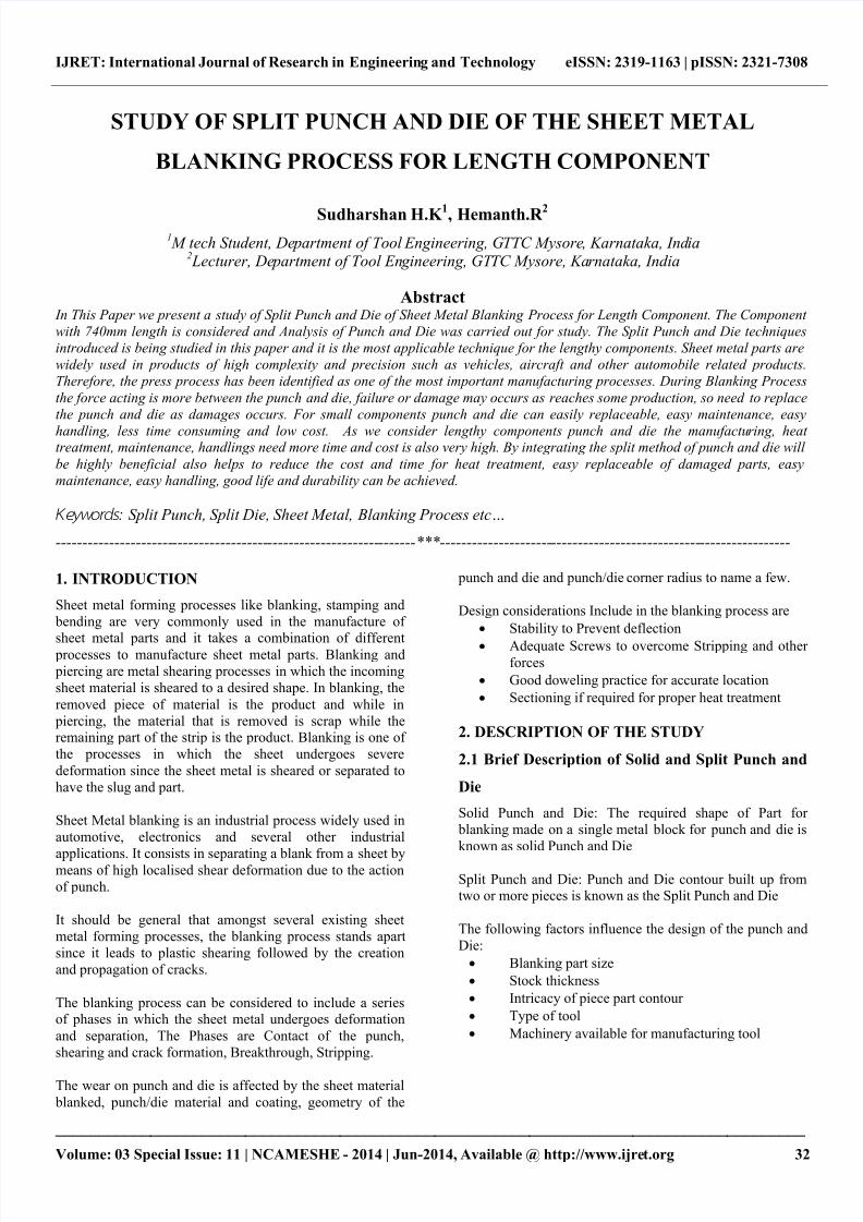
3.1 Component Study
The component drawing is studied to know the importantfeatures, its geometry, Stages of operations, Special and
important features of the component. The 3D views of the
component as shown in Fig 1.
Fig -1: Component 3D Views
3.2 Component Details
The component details have given below:
Name of the component: a bumper external top panel
Material: Cold Rolled Carbon Steel Sheet
Designation: IS: 513 Grade „D‟
Thickness: 2 mmComponent Length: 740 mm
3.3 Design Concept of Split Punch and Die
Designing press punch and die is a vital step in the
development of press processes, The Conceptual Design
was carried out using the AutoCAD and 3D Model was
done using the CATIA Software for the Split Punch and
Die.
Split Punch is assembled with Punch Holder. The
Assembled and Explode view of Split Punch is as shown in
Fig.2.
Fig -2: Assembled and Explode view of Split Punch
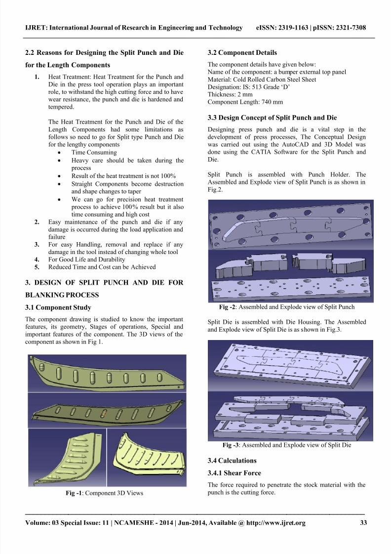
Split Die is assembled with Die Housing. The Assembled
and Explode view of Split Die is as shown in Fig.3.
Fig -3: Assembled and Explode view of Split Die
3.4 Calculations
3.4.1 Shear Force
The force required to penetrate the stock material with the punch is the cutting force.

7/27/2019 Study of Split Punch and Die of the Sheet Metal Blanking Process for Length Component
http://slidepdf.com/reader/full/study-of-split-punch-and-die-of-the-sheet-metal-blanking-process-for-length 3/5
IJRET: International Journal of Research in Engineering and Technology eISSN: 2319-1163 | pISSN: 2321-7308
_______________________________________________________________________________________
Volume: 03 Special Issue: 11 | NCAMESHE - 2014 | Jun-2014, Available @ http://www.ijret.org 34
The formula for determining cutting forces takes into
account the thickness of the work material, the perimeter of
the cut edge, and the shear strength of the stock material.
The cutting force is calculated below
Cutting/Shear force = (L x t x f s)
= (1642.9222x 2 x 260)= 854319.54 N
= 854.31 KN
Where,
L= perimeter of the cut edge = 1642.9222mm
t = thickness of the work material = 2mm
f s = shear strength of the stock material = 260 N/mm2
3.4.2 Clearance
Clearance is defined as the intentional space between the
punch cutting edge and die cutting edge. Clearance is
expressed as the amount of clearance per side.
Cutting Clearance = c x t x (√f s /10)
= 0.01 x 2 x (√260/10)
= 0.10 mm/side
Where,
c = Constant = 0.005 for very accurate component
= 0.01 for normal component.
t = thickness of the work material = 2mm
f s = shear strength of the stock material = 260 N/mm2
3.5 Selection of the Tooling Material
The Work Material is IS: 513 Grade „D‟ Mechanical Properties: Yield Stress: 280 N/mm2
Tensile Stress: 380 N/mm2
Shear Strength: 260 N/mm2
Chemical Composition: C%: 0.12
Mn%: 0.5
P%: 0.04
S%:0.04
Punch Material: D2
Punch Holder Material: MS
Die Material: D2
Die Housing Material: MS
Die Ejector Material: D2
D2 material is used for punch, die and die ejector. AISI D2
tool steel is one of the carbon steels alloyed with Mo, Cr,
and V, is widely used for various dies and cutters for its high
strength and wear resistance due to formation of chrome
carbide in heat treatment.
Mild Steel is used for punch holder and die housing. Mild
steel is the most versatile, least expensive and widely used
engineering material which has found extensive application
in various industries.
4. ANALYSIS OF SPLIT PUNCH AND DIE
The analysis of Blanking Split Punch and Split die is carried
out by the computer application engineering (CAE) software
has been successfully executed for the evaluation of
maximum transverse deflection and stresses. The stress
analysis is mainly intended to estimate the load carryingcapacity of the members.
Mechanics of materials and theory of elasticity approaches
have been developed and successfully applied for the stress
analysis of the members. The results reveal that by
integrating CAD/CAE will be highly beneficial to
Designer`s and thereby saving lot of expenditures by
avoiding repeated costly tryouts, changing the die and punch
designs and more over the development of the product /
component lead time is greatly reduced.
4.1 Split Punch Analysis
4.1.1 Solid Mesh
Fig -4: Solid Mesh of Split Punch
4.1.2 Static Nodal Stress:
Fig -5: Static Nodal Stress of Split Punch

7/27/2019 Study of Split Punch and Die of the Sheet Metal Blanking Process for Length Component
http://slidepdf.com/reader/full/study-of-split-punch-and-die-of-the-sheet-metal-blanking-process-for-length 4/5
IJRET: International Journal of Research in Engineering and Technology eISSN: 2319-1163 | pISSN: 2321-7308
_______________________________________________________________________________________
Volume: 03 Special Issue: 11 | NCAMESHE - 2014 | Jun-2014, Available @ http://www.ijret.org 35
4.1.3 Static Displacement
Fig -6: Static Displacement of Split Punch
4.1.4 Static Strain
Fig -7: Static Strain of Split Punch
4.1.5 Analysis Results for Split Punch:
Table -1: Analysis Results for Split Punch
Type Static Nodal
Stress
Static
Displacement
Static
Strain
Minimum 0 N/mm2 0 mm 0
Maximum 170.7 N/mm2 0.032 mm 0.001
4.2 Split Die Analysis
4.2.1 Solid Mesh
Fig -8: Solid Mesh of Split Die
4.2.2 Static Nodal Stress:
Fig -9: Static Nodal Stress of Split Die
4.2.3 Static Displacement:
Fig -10: Static Displacement of Split Die
7/27/2019 Study of Split Punch and Die of the Sheet Metal Blanking Process for Length Component
http://slidepdf.com/reader/full/study-of-split-punch-and-die-of-the-sheet-metal-blanking-process-for-length 5/5
IJRET: International Journal of Research in Engineering and Technology eISSN: 2319-1163 | pISSN: 2321-7308
_______________________________________________________________________________________
Volume: 03 Special Issue: 11 | NCAMESHE - 2014 | Jun-2014, Available @ http://www.ijret.org 36
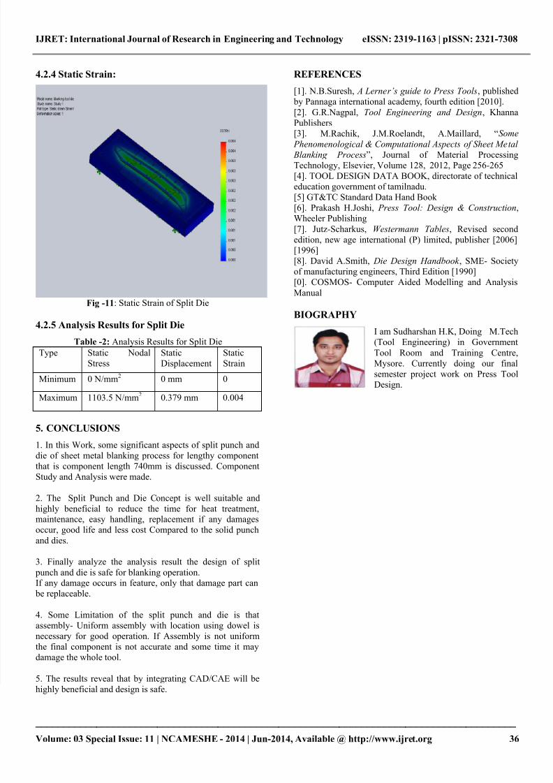
4.2.4 Static Strain:
Fig -11: Static Strain of Split Die
4.2.5 Analysis Results for Split Die
Table -2: Analysis Results for Split Die
Type Static Nodal
Stress
Static
Displacement
Static
Strain
Minimum 0 N/mm2 0 mm 0
Maximum 1103.5 N/mm2 0.379 mm 0.004
5. CONCLUSIONS
1. In this Work, some significant aspects of split punch and
die of sheet metal blanking process for lengthy component
that is component length 740mm is discussed. Component
Study and Analysis were made.
2. The Split Punch and Die Concept is well suitable and
highly beneficial to reduce the time for heat treatment,maintenance, easy handling, replacement if any damages
occur, good life and less cost Compared to the solid punch
and dies.
3. Finally analyze the analysis result the design of split
punch and die is safe for blanking operation.If any damage occurs in feature, only that damage part can
be replaceable.
4. Some Limitation of the split punch and die is that
assembly- Uniform assembly with location using dowel is
necessary for good operation. If Assembly is not uniform
the final component is not accurate and some time it may
damage the whole tool.
5. The results reveal that by integrating CAD/CAE will be
highly beneficial and design is safe.
REFERENCES
[1]. N.B.Suresh, A Lerner’s guide to Press Tools, published
by Pannaga international academy, fourth edition [2010].
[2]. G.R.Nagpal, Tool Engineering and Design, Khanna
Publishers
[3]. M.Rachik, J.M.Roelandt, A.Maillard, “Some Phenomenological & Computational Aspects of Sheet Metal
Blanking Process”, Journal of Material ProcessingTechnology, Elsevier, Volume 128, 2012, Page 256-265
[4]. TOOL DESIGN DATA BOOK, directorate of technical
education government of tamilnadu.
[5] GT&TC Standard Data Hand Book
[6]. Prakash H.Joshi, Press Tool: Design & Construction,
Wheeler Publishing
[7]. Jutz-Scharkus, Westermann Tables, Revised second
edition, new age international (P) limited, publisher [2006]
[1996]
[8]. David A.Smith, Die Design Handbook , SME- Society
of manufacturing engineers, Third Edition [1990][0]. COSMOS- Computer Aided Modelling and Analysis
Manual
BIOGRAPHY
I am Sudharshan H.K, Doing M.Tech
(Tool Engineering) in Government
Tool Room and Training Centre,
Mysore. Currently doing our final
semester project work on Press Tool
Design.