study and analysis of residual stresses in...
TRANSCRIPT

STUDY AND ANALYSIS OF RESIDUAL STRESSES IN ELECTRO-DISCHARGE MACHINING (EDM)
A THESIS SUBMITTED IN PARTIAL FULFILLMENT
OF THE REQUIREMENTS FOR DEGREE OF
Bachelor of Technology
in
Mechanical Engineering
By
PANKAJ KUMAR SONI
Roll No : 10303003
RAJU GHOLLEY
Roll No : 10303005
Department of Mechanical Engineering
National Institute of Technology
Rourkela
2007

2
STUDY AND ANALYSIS OF RESIDUAL STRESSES IN ELECTRO-DISCHARGE MACHINING (EDM)
A THESIS SUBMITTED IN PARTIAL FULFILLMENT
OF THE REQUIREMENTS FOR DEGREE OF
Bachelor of Technology
in
Mechanical Engineering
By PANKAJ KUMAR SONI
Roll No : 10303003
RAJU GHOLLEY
Roll No : 10303005
Under the Guidance of
Prof. C.K. Biswas
Department of Mechanical Engineering
National Institute of Technology
Rourkela
2007
2

3
National Institute of Technology ROURKELA
CERTIFICATE
This is to certify that the thesis entitled , “STUDY AND ANALYSIS OF RESIDUAL STRESSES IN ELECTRO-DISCHARGE MACHINING (EDM)” submitted by Sri Pankaj
Kumar Soni and Sri Raju Gholley in partial fulfillment of the requirements for the award of
Bachelor of Technology in Mechanical Engineering at the National Institute of Technology,
Rourkela (Deemed University) is an authentic work carried out by them under my supervision
and guidance.
To the best of my knowledge, the matter embroiled in the thesis has not been submitted to any
other University/ Institute for the award of any Degree or Diploma.
Date : Prof. C.K. BISWAS
Dept. of Mechanical Engg.
National Institute of Technology
Rourkela - 769008
3
4
ACKNOWLEDGEMENT
We deem it a privilege to have been the students of Mechanical Engineering stream in National
Institute of Technology, ROURKELA.
Our heartfelt thanks to Prof C.K. Biswas, our project guide who helped us to bring out this
project in good manner with his precious suggestion and rich experience.
We take this opportunity to express our sincere thanks to our project guide for co-operation and
to reach a satisfactory conclusion.
PANKAJ KUMAR SONI
ROLL NO : 10303003
RAJU GHOLLEY
ROLL NO : 10303005
4

5
CONTENTS page no Abstract 6-7
List of Figures 8
List of Tables 8 CHAPTER 1 General Introduction 9
1.1 Introduction of EDM 10 1.2 Basic principle of EDM 11-12
1.3 Some of the important parameters implicated 12
in EDM process
1.4 Applications of EDM 13
CHAPTER 2 Brief Introduction of the Project 14
2.1 Causes of residual stresses in EDM process 15
2.2 Different methods for measuring residual stress in EDM 16
2.2.1 EDM hole drilling Method 16
2.2.2 Finite Element Method 16
2.2.3 X-Ray Diffraction Method 16-17
2.2.3 Bending Deflection Method 17
2.2.4 Layer Removal Method 17-18
CHAPTER 3 Literature Review 19 3.1 Experimental studies on residual stresses 20-21
3.2 Crack causes and their experimental studies 21-22
3.3 Objective of the present work 22 CHAPTER 4 Experimental Work 23 4.1 Procedure of the Experiment 24
4.2 Tables for sample 1,2,3 25-26
CHAPTER 5 Results and Discussions 27
5.1 Phase Transformations 28-29
5.2 Crater Shape 29-35
5.3 Conclusion 34-35
CHAPTER 6 Reference & Bibliography
5

6
ABSTRACT Technological advances have led to an increasing use of high strength, high hardness materials in
manufacturing industries. In machining of these materials, traditional manufacturing processes
are increasingly being replaced by more advanced techniques such as electro-discharge
machining (EDM), ultrasonic machining (USM), electric chemical machining (ECM) and laser
machining. EDM has found widespread application in MEMS, tool and mould industries and
aerospace industries. Therefore, promoting the quality of the EDM process by developing a
thorough understanding of the relationship between the EDM parameters and the machined
surface integrity has become a major research concern. Electric discharge machining removes
materials by melting and vaporizing caused by the high heat within the discharge column.
Furthermore, EDM can easily fabricate the precision and complicated parts by choosing the
appropriate machining conditions to effectively control the amount of removed materials.
Although EDM can obtain fine surface integrity and precise dimensions under finishing
condition, the rough machining condition produces larger and deeper discharge craters since the
great quantity of the melted material is removed. Furthermore, the melted material is not
removed completely because the impulse force is insufficient to flush away the melted material
at the end of discharge interval. The remaining melted material is solidified to form a recast layer
that distributes micropores and cracks due to the effect of thermal stress during cooling. Thus,
the microscopic feature of machined surface is severely coarse that significantly deteriorates the
usage life and precision of machinery parts.
EDM involves the complex interaction of many physical phenomena. The
electric spark between the anode and the cathode generates a large amount of heat over a small
area of the work-piece. A portion of this heat is conducted through the cathode, a fraction is
conducted through the anode, and the rest is dissipated by the dielectric. The duration of the
spark is of the order of microseconds and during this time, a plasma channel is formed between
the tool and the work-piece. Electrons and ions travel through this plasma channel. The plasma
channel induces a large amount of pressure on the work-piece surface as well. This pressure
holds back the molten material in its place. As the plasma starts forming it displaces the
dielectric fluid and a shock wave passes through the fluid. As soon as the spark duration time is
over and the spark collapses, the dielectric gushes back to fill the void. This sudden removal of
pressure results in a violent ejection of the molten and vaporized material from the work-piece
surface. Ejected molten particles quickly solidify in contact with the colder fluid and are
6

7
eventually flushed out by the dielectric. Small craters are formed at locations where material has
been removed. Multiple craters overlap each other and the machined surface that is finally
produced consists of numerous overlapping craters. Although molten material ejection is not
the only means of material removal in EDM, it is, however, the dominant mode of material
removal in case of metals. During machining the local temperature in the workpiece gets close to
the vaporization temperature of the material. Thus, phase transformation from solid to liquid as
well as liquid to vapor occurs during the heating cycle. Part of the transformed material is
removed but the rest re-solidifies on the surface of the workpiece. This re-solidified layer is
usually called the white layer, as it is not easily etchable. EDM processes carried out in
hydrocarbon dielectrics lead to the partial breakdown of dielectrics and this further leads to some
diffusion of carbon Below the re-solidified white layer lies a second layer that does not melt but
is still affected by heat. For steels, during the cool-down cycle, solid-state transformations occur
in this heat-affected zone because the highest temperature reaches beyond the austenite
transformation temperature. Finally, all the non-uniform heating and cooling give rise to
transient and residual stresses in the workpiece. As a result of these residual stresses surface
cracks may be formed in the white layers. Usually, residual stresses are not high enough to cause
sub-surface cracks in the parent material but may lead to detrimental effects when the machined
work-piece is used in applications.
This work is intended on analyzing the cause of residual stress in EDM process. It is also
showing how current variation brings about a change in the surface characteristics and how the
microstructure variation occurs because of subsequent sparks with constant magnitude. This is
studied to draw a relationship between the micro structural change and the generation of residual
stresses. Scanning Electron Microscope (SEM) images taken from the samples show the surface
variation at different currents. A comparative study shows current variation is a factor for the
craters developed at the EDMed surface, and that higher magnitude of current changes the grain
structure of the sample drastically and intensifies the magnitude of residual stresses generated in
EDMed sample. The solid-solid transformation is brought about at a higher temperature (at
higher current) and sample EDMed at higher current is seen to have greater surface roughness.
7

8
List of Figures Page No
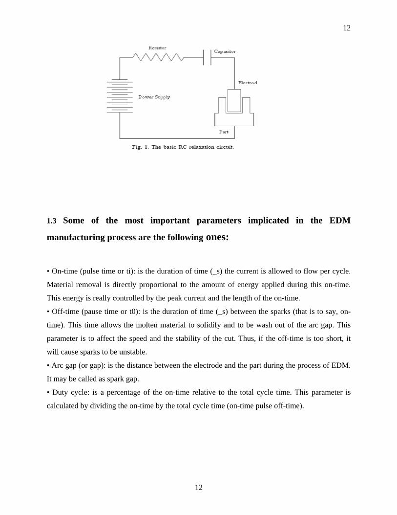
Fig-1.1 The Basic RC Relaxation Circuit 12
Fig- 2.1 Close-up of the EDM Machining Region 15
Fig-3.1 EDMed Surface with Surface Cracks and Sketch 22
of Sub-surface Regions
Fig-4.1 Schematic Diagram of the EDM setup used 24
in the experiment
Fig 5.1 UnEDMed surface of En-19 30
Fig 5.2 SEM photograph of EDMed surface of 31
En-19 at 5 amp current
Fig 5.3 SEM photograph of EDMed surface of 32
En-19 at 25 amp current
Fig 5.4 SEM photograph of and EDMed surface of 33
En-19 at 45 amp current
List of Tables Page No
Table-4.1 Sample 1 25
Table-4.2 Sample 2 25
Table-4.3 Sample 3 26
8

9
CHAPTER 1 General Introduction
9

10
1.1 INTRODUCTION OF EDM :
Electrical discharge machining is a non-traditional manufacturing process based on removing
material from a part by means of a series of recurring electrical discharges (created by electric
pulse generators at short intervals) between a tool called electrode and the work piece in the
presence of a dielectric fluid. This fluid makes it possible to flush eroded particles (mainly in the
form of hollow spheres) from the gap and it is really important to maintain this flushing
continuously.
The first EDM application was carried out by Mr. and Mrs. Lazarenko in the Technical Institute
of Moscow during the Second World War . The first of the two important improvements, also
carried out by these Soviet scientists, which make it feasible to elevate this electrical technique to
the category of manufacturing process was the RC relaxation circuit, which provided the first
consistent dependable control of pulse times. The second innovation consisted of adding a simple
servo control circuit in order to find and hold a given gap automatically. In spite of these first
trials and innovations, EDM technology got nearly unknown until the 1950s. At this time, this
technique began to be interesting for the industrial marketing mainly in the USA. Some of the
causes that eased a much more widespread use of the EDM process were the vacuum tubes, its
combination with the basic RC relaxation circuit and finally, the development of the transistor.
These solid state devices were able to provide high currents and a really much faster switch on
and off than the previous vacuum tubes. Nowadays, EDM is widely used both in the European
market and in the American market.
Therefore, EDM is the technique used in industry for high-precision machining of all types of
conductive materials such as metals, metallic alloys, graphite, ceramics, etc., of any hardness.
10

11
1.2 BASIC PRINCIPLE OF EDM PROCESS: EDM machining is carried out by means of electric sparks that jump between two electrodes
subjected to a voltage and submerged in a dielectric fluid. Thus, the voltage applied to them must
be enough to create an electric field higher than the dielectric rigidity of the fluid used in the
process.As a consequence of this electric field,positive ions and electrons are
accelerated,producing a discharge channel that becomes conductive. It is just at this point when
the spark jumps causing collisions between ions and electrons and creating a channel of plasma.
A sudden drop of the electric resistance of the previous channel allows that current density
reaches very high values producing an increase of ionization and the creation of a powerful
magnetic field.
These effects make a little part of metal volume melt or even vaporise. In these
conditions, that is, ions and electrons crashing among them and therefore creating high
temperatures in both poles, a gas all or bubble is formed around the plasma channel and then
begins to grow providing just at the end of the discharge a large ball of gas. In this situation,
electric current is shut off and the plasma channel collapses
producing the spark to disappear .Due to the sudden decrease of internal pressure of the gas ball,
the dielectric fluid breaks it making the ball implode, that is, explode inwards. As a consequence
of this implosion, an ejection of molten metal is carried out and, afterwards, this ejected molten
material solidifies in the form of little balls formed the so called EDM splinter or debris.
Basically, there are two different types of EDM:
1)Die-sinking 2) wire-cut.
Die-sinking EDM reproduces the shape of the tool used (electrode) in the part wire-cut EDM a
metal wire (electrode) is used to cut a programmed outline into the piece. In spite of the
advantages that present EDM processes, one of the most important drawbacks is the high
manufacturing time. This is really important when obtaining low values of surface roughness is
pretended .In such case, an inadequate selection of operation conditions may cause quite high
process times without achieving an improvement on the surface roughness properties.
11
12
1.3 Some of the most important parameters implicated in the EDM
manufacturing process are the following ones:
• On-time (pulse time or ti): is the duration of time (_s) the current is allowed to flow per cycle.
Material removal is directly proportional to the amount of energy applied during this on-time.
This energy is really controlled by the peak current and the length of the on-time.
• Off-time (pause time or t0): is the duration of time (_s) between the sparks (that is to say, on-
time). This time allows the molten material to solidify and to be wash out of the arc gap. This
parameter is to affect the speed and the stability of the cut. Thus, if the off-time is too short, it
will cause sparks to be unstable.
• Arc gap (or gap): is the distance between the electrode and the part during the process of EDM.
It may be called as spark gap.
• Duty cycle: is a percentage of the on-time relative to the total cycle time. This parameter is
calculated by dividing the on-time by the total cycle time (on-time pulse off-time).
12

13
1.4 APPLICATIONS OF EDM:
1.It is used to machine extremely hard materials that are difficult to machine like alloys, tool
steels, tungsten carbides etc.
2.It is used for forging, extrusion, wire drawing, thread cutting.
3.It is used for drilling of curved holes.
4.It is used for internal thread cutting and helical gear cutting.
5.It is used for machining sharp edges and corners that cannot be machined effectively by other
machining processes.
6. Higher Tolerance limits can be obtained in EDM machining. Hence areas that require higher
surface accuracy use the EDM machining process.
7.Ceramic materials that are difficult to machine can be machined by the EDM machining
process.
13

14
CHAPTER 2
BRIEF INTRODUCTION OF THE PROJECT
14

15
2.1 CAUSE OF RESIDUAL STRESSES IN EDM PROCESS:
EDM generates residual stresses mainly due to the non homogeneity of heat flow and
metallurgical transformations. Investigation of the residual stresses of electric discharge
machined components revealed their tensile nature, the extremely narrow superficial zone where
they appear, their high magnitude at the surface layers, and their increase with increasing pulse
energy.Earlier attempts to measure residual stresses due to EDM conducted by several authors
have shown that high tensile residual stresses are developed. These stresses were found to
approach the upper tensile strength of the material at the immediate surface, and then fall rapidly
to a relatively low value before giving way to small residual compressive stresses in the core of
the material. The stresses were deemed to arise mainly as a result of the thermal contraction of
the resolidified metal, which was not expelled from the craters, onto the relatively unaffected
parent metal, inducing plastic deformation and biaxial tensile stress .
15
16
2.2 DIFFERENT METDHODS OF MEASURING RESIDUAL STRESSES:
2.2.1 EDM-HOLE DRILLING METHOD:
In this study the EDM drilling process is used to measure the residual stresses of high-
performance materials, whose stress state is difficult to obtain by a widely used technology
called high-speed (HS) hole-drilling method (ASTM Standard E837). . The experimental results
in this method reveal that the stress measurement curves of both EDM conditions, which have
the same EDM energy, are parallel with the ideal curve. Therefore the results of EDM hole-
drilling method can be positively calibrated by a constant, and it depicts the feasibility of
residual measurement on materials with high hardness and wear resistance.
2.2.2 FINITE ELEMENT METHOD:
A finite element-based model for the electric discharge machining ( EDM) process is
presented. IN this method we use process parameters such as power input, pulse duration, etc.,
to predict the transient temperature distribution, liquid- and solid-state material transformation
and
,
residual stresses that are induced in the workpiece as a result of a single-pulse discharge.
An attractive feature of this method is its ability to predict the shape of the crater that is formed
as a result of the material removal. But in this method ,improvements to simulate the effects of
multiple pulses hasn’t been undertaken in the near future.
2.2.3 X-RAY DIFFRACTION METHOD :
In this method parallel beam modification to determine the residual stress profile of electric
discharge machined micro alloyed steel. Considerable amount of residual stresses is observed at
the sub-surface layer and that the peak stresses were almost independent of the discharge energy
and approaches the ultimate tensile strength of the material. The effect of increase in discharge
energy was described as increase in depth where the peak residual stress occurs. This was related
16

17
to the intensification of the surface cracking with energy. They observed lower stresses for dual
phase samples compared to micro alloyed one, although the difference in strength between these
steels is not significant. They have concluded this situation as the influence of transformation
stresses due to phase changes. The residual stress values increase from the bulk material to a
maximum and then decrease again near to the surface. This decrease is related to crack formation
since the residual stresses exceed the fracture strength of the material. It is noticed that the depth
of the maximum stress value corresponds to the average depth of the thermal cracks network
induced by EDM.
2.2.4 BENDING DEFLECTION METHOD:
The bending deflection method is based on continuous material removal. It is observed that the
peak stress is not located at the surface, but somewhat below for roughing. They explained this
situation by the fact that the white layer has a lot of cavities and micro-cracks, which cause
relaxation of the residual stresses. After reaching the peak value, the tensile stresses decrease and
switch to small compressive values at a certain penetration depth below the surface. The
maximum stress value decreases considerably in whereas the depth of maximum stress and the
penetration. depth of the tensile stress are unchanged.
2.2.5 THE PRINCIPLE OF LAYER REMOVAL METHOD:
The principle of layer removal method depends on the balance of internal stresses and moments
when residual stresses are gradually removed from the material in form of thin layers using
chemical or electro-chemical machining. Stressed layers from a thin parallelepiped test
specimen, which usually include residual stresses in one of their planes, are removed
successively and resulting strains or deformations are measured. Since the resulting deformations
of the analyzed part can be related to stresses in removed layer by equilibrium of forces and
moments, residual stresses can be determined using simple elasticity theory. In this method, only
17
18
the principal stress component parallel to the axis of the test specimen can be calculated. An
electric discharge machined surface is produced with applying consecutive spark discharges,
which bring about overlapping craters that is randomly distributed over the entire surface.
Supposing that each discharge is axisymmetric, a biaxial stress field with equal stress magnitudes
can be assumed. The transverse stresses could be considered negligible due the thermal nature of
the process. Therefore, only one directional measurement of the curvature is sufficient while
knowing that a two dimensional stress is present. One of the most appropriate machining
processes to remove stressed layers from an analyzed part is electrochemical machining since it
does not add any additional stresses and it is possible to remove thin layers which is crucial for
the measurements.
18

19
CHAPTER 3
LITERATURE REVIEW
19

20
3.1 EXPERIMENTAL STUDIES ON RESIDUAL STRESS:
EDM involves the complex interaction of many physical phenomena. The electric spark between
the anode and the cathode generates a large amount of heat over a small area of the workpiece. A
portion of this heat is conducted through the cathode, a fraction is conducted through the anode,
and the rest is dissipated by the dielectric. The duration of the spark is of the order of
microseconds and during this time a plasma channel is formed between the tool and the
workpiece. Electrons and ions travel through this plasma channel.
The plasma channel induces a large amount of pressure on the workpiece surface as well. This
pressure holds back the molten material in its place. As the plasma starts forming it displaces the
dielectric fluid and a shock wave passes through the fluid. As soon as the spark duration time is
over and the spark collapses, the dielectric gushes back to fill the void. This sudden removal of
pressure results in a violent ejection of the molten and vaporized material from the workpiece
surface. Ejected molten particles quickly solidify in contact with the colder fluid and are
eventually flushed out by the dielectric. Small craters are formed at locations where material has
been removed. Multiple craters overlap each other and the machined surface that is finally
produced consists of numerous overlapping craters. During machining the local temperature in
the workpiece gets close to the vaporization temperature of the material .Thus, phase
transformation from solid to liquid as well as liquid to vapor occurs during the heating cycle.
Part of the transformed material is removed but the rest re-solidifies on the surface of the
workpiece. This re-solidified layer is usually called the white layer, as it is not easily
etchable.EDM processes carried out in hydrocarbon dielectrics lead to the partial breakdown of
dielectrics and this further leads to some diffusion of carbon into the white layer . It has been
reported by many researchers that white layers formed in the presence of hydrocarbon dielectrics
contain higher percentages of carbon than those machined in de-ionized water due to the
diffusion of carbon into the surface layers.Below the re-solidified white layer lies a second layer
that does not melt but is still affected by heat. For steels, during the cool-down cycle, solid-state
transformations occur in this heat-affected zone because the highest temperature reaches beyond
the austenite transformation temperature. Experimental data shows that this heat-affected layer
transforms mostly to martensite along with some retained austenite for steel samples.Finally, all
the non-uniform heating and cooling give rise to transient and residual stresses in the workpiece.
20
21
As a result of these residual stresses surface cracks may be formed in the white layers. Usually,
residual stresses are not high enough to cause sub-surface cracks in the parent material but may
lead to detrimental effects when the machined workpiece is used in applications.
3.2 Cracks Causes:
Crack formation can be attributed to the presence of thermal stress and tensile stress within the
machined component. Thermal stress is produced when the electrode discharges bombard the
surface of the sample during the machining process. Tensile stress within the sample is generated
because not all of the material which melts during the machining process is swept away from the
component’s surface by the dielectric. Due to the ingress of carbon, the melted material contracts
more than the unaffected parent part during the cooling process, and when the stress in the
surface exceeds the material’s ultimate tensile strength, cracks are formed. Since both tension
cracks and voids form during the cooling stage, there would appear to be some relationship
between the two. Although results from previous studies and have indicated that cracking
increases as the pulse energy increases, the exact relationship between cracking and EDM
parameters has never been presented.
Observation of the machined surface, and the sample sections, reveals that the surface cracks are
often micro-cracks. The high magnification microscope shows that cracks exist in the white
layer; initiating at its surface, and traveling down perpendicularly towards the parent material. In
the vast majority of cases the cracks terminate within the white layer, or just on the interface of
the white layer and the parent material. Only rarely do the cracks penetrate the entire white layer
thickness to extend into the parent material.
If one material sample is considered in isolation, surface deviation reveals that different EDM
parameters cause different surface crack densities. However, since surface cracking is a potential
source of component failure, it is necessary to qualify the degree of cracking by means of some
objective standard. Since it is not easy to quantify the cracking in terms of an estimation of the
width, length, or depth of the crack, or even by the amount of cracking, this study defines a
“surface crack density”, i.e. the total length of cracks (cm) in a unit area (cm2) to evaluate the
21

22
severity of cracking.
3.2 OBJECTIVE OF THE PRESENT WORK:
The objective of the present work is to:
1)study the various causes of residual stresses induced during EDM process and analyse the
different methods for measuring the residual stresses in EDM process.
2)study and analyse the phase transformation and the change of microstructure in an EDMed
sample that causes residual stress development.
3)Analyse the cracks and the surface defects ocuring at different currents in EDMed sample.
22

23
CHAPTER 4
EXPERIMENTAL WORK
23

24
4.1 Procedure:
En-19 alloy steel is used is as the work piece in this experiment. The sample was cut into
standard dimension using hacksaw at metallurgy lab. The diameter of the sample is 50 mm and
the thickness is 13 mm. Three samples of same dimension were prepared. The three different
samples were grinded and polished in the grinding machine. Grinding was done in order to level
the work-piece. Then keeping the pulse rate constant and varying the current each sample was
EDMed for 7-8 minutes. The first sample was machined at 5 amp current. The second sample
was machined at a current of 25 amp. while The third sample was machined at a current of 45
amp. Each of the samples was then polished with diesel to clear the carbon deposits. All the three
samples were then viewed under Scanning Electron Microscope. The surface characteristics of
each sample EDMed at different current was studied. The phase transformation analysis was
done which gives rise to residual stresses.
The formation of cracks and surface defects are studied from the images obtained from SEM
images.
4.2.1 TABLE 1: Sample no 1
Step X Y Z Ip Ton t Vg SEN ASEN Tw Tp Pol
S 1 0.0000 0.0000 -9.000 5 100 10 50 7 2 1.5 0.3 +ve
E 2 0.0000 0.0000 -9.000 5 100 10 50 7 2 1.5 0.5 +ve
4.2.2 TABLE 2: Sample no 2
Step X Y Z Ip Ton t Vg SEN ASEN Tw Tp Pol
S 1 0.0000 0.0000 -9.000 25 100 10 50 7 2 1.5 0.3 +ve
E 2 0.0000 0.0000 -9.000 25 100 10 50 7 2 1.5 0.5 +ve
24

25
4.2.3 TABLE 3: Sample no 3
Step X Y Z Ip Ton t Vg SEN ASEN Tw Tp Pol
S 1 0.0000 0.0000 -9.000 45 100 10 50 7 2 1.5 0.3 +ve
E 2 0.0000 0.0000 -9.000 45 100 10 50 7 2 1.5 0.5 +ve
25

26
CHAPTER 5
RESULTS AND DISCUSSIONS
26

27
5.1 Phase transformation:
The dramatic temperature changes in the workpiece associated with EDM induce change of
phase in the material. Regions that achieve the melting point are called fusion or molten region.
For the molten areas the phase changes from solid to liquid (and perhaps to gas as well). The
neighborhood of the fusion zone experiences similar rise and fall in temperature but the highest
temperature does not necessarily reach the melting point of the workpiece. This region is called
the heat-affected region. The temperature cycle observed near the machined area of the
workpiece is in many ways similar to the temperature cycles involved in many welding
processes. Like in welding, two distinct zones, a fusion zone and a heat-affected zone are
observed after EDM machining. While the fusion zone experiences solid–liquid phase
transformation, the heat-affected zone experiences solid–solid phase transformation. Solid–
solid phase transformations in steel are initiated when the temperature is raised above austenite
transformation or A3 temperature. Once this temperature is crossed the parent material
transforms to austenite. Subsequently, as the austenite cools several daughter phases, such as
ferrite, pearlite or banite could be created. These solid-state transformations are controlled by the
cooling rate of the transformed austenite and the composition of the parent material. TTT or the
CCT diagrams for different steel compositions are excellent tools to predict the fractions of
daughter phases that are created during a certain cool-down process. Mathematical
representations of the TTT diagrams were used in the past along with process simulation tools to
predict the fractions of daughter phases formed during welding and heat treatment [18–21].These
tools enable the user to track the formation of Ferrite, Pearlite and Banite during cool down. The
untransformed austenite that remains after the martensite transformation temperature is reached
promptly transforms to martensite.
For solid-state phase transformation, the cooling rate is an important factor. The faster the
cooling rates the more propensities there is for the formation of martensite. In the case of EDM,
cooling rate is extremely high. It is much higher than water quenching (which shows one of the
highest cooling rates among the traditional processes). Thus, it is expected that most of the heat-
affected zone area will have transformed to martensite. After a portion of the molten layer is
removed when the discharge collapses, the remaining material solidifies very quickly to form a
thin layer of re-solidified material on the surface of the work-piece. Single spark experiments
show the formation of craters on work-piece surfaces. The thin re-solidified layer observed on
27

28
the machined surface is really a result of overlapping craters formed due to numerous
overlapping sparks. The thin re-solidified layer is generally called the white layer because it is
difficult to etch using standard etching agents like nitol, etc. We observe several features within
the white layer by employing non-traditional etching techniques. We described three sub-layers
within the white layer. Two of these were formed due to simultaneous cooling from the outer
surface inwards and from the inner surface outwards. These two layers are characterized by long
dendritic structures. A third layer was observed sandwiched in between these two layers. In this
current model it is possible to predict the extent of the fusion zone (i.e. the re-solidified molten
layer) and the heat-affected zone that mostly contains martensitic material. Heat transfer results
provide transient temperatures at all nodes. Nodal temperature data determines the region that
melts and the region that experiences temperature above the A3 temperature but stays below the
fusion temperature. The fusion region loses some elements to simulate material removal. The
rest solidifies to form the fusion zone. Due to the high cooling rate the solid-state transformation
produces predominantly martensite. So all the heat-affected zone is shown to transform into
martensite.
5.2 Crater Shape:
The final shape of the crater as a result of a single pulse is quite well known to researchers. It is a
depression in the middle with edges that are raised above the surface (photographs are included
in this document). This shape is formed as a result of two effects. During the plasma-on time the
plasma pressure holds the liquid metal in place under pressure. This may force some of the fluid
to be pushed towards the side and try and escape the pressure. It is assumed these liquids re-
solidify to form the protruding edges around the hole. When the plasma pressure is released
violently ejected liquid metal splatters and this leaves splashy re-solidified material all over the
crater. In the simulation the depression within the crater is automatically simulated when the
molten material is removed. To simulate the protruding edges a pressure boundary condition is
applied on the molten pool and the pressure is kept on until the pulse-on time. This forces some
of the molten material to severely shear and form the edge around the pool.
28

29
Fig 5.1 UnEDMed surface of En-19
Fig 5.1 shows the UnEDMed surface of Sample 1 which is of material En-19 at 150
magnification on SEM screen.
29

30
Fig 5.2 SEM photograph of EDMed surface of En-19 at 5 amp current
Sample 1:
SEM photograph of Sample 1 EDMed with current of 5 ampere (A) is shown in Fig. 5.2. From
the figure it is evident that the surface roughness is better because of the less intensity of current.
As seen from the figure, there is little distortion in the microstructure and almost no cracks
develop. The phase transformed in this case is hence less because the thickness of white layer
formed would be less, hence it is seen that the sample undergoes little transformation of phase
and subsequently less residual stresses develop in sample no 1.
30

31
Fig 5.3 SEM photograph of EDMed surface of En-19 at 25 amp current
Sample 2:
Sample 2 EDMed at a current of 25 amp shows slight development of craters which would
initiate cracks later (ref Fig 5.3). This sample undergoes constant overlapping of subsequent
sparks which results in solid-solid transformation because of higher heat generation in the fusion
zone at higher current of 25 amp. Hence solid transformation results in the development or
generation of stresses below the solidified layer which is the residual stresses in the sample. The
SEM pictures depict that there is higher surface roughness in this sample machined at a higher
current and the microstructure is seen to vary largely from the unEDMed surface (ref. Fig. 5.1),
hence giving rise to residual stresses in the sample, whose magnitude is higher than that of
sample 1.
31
32
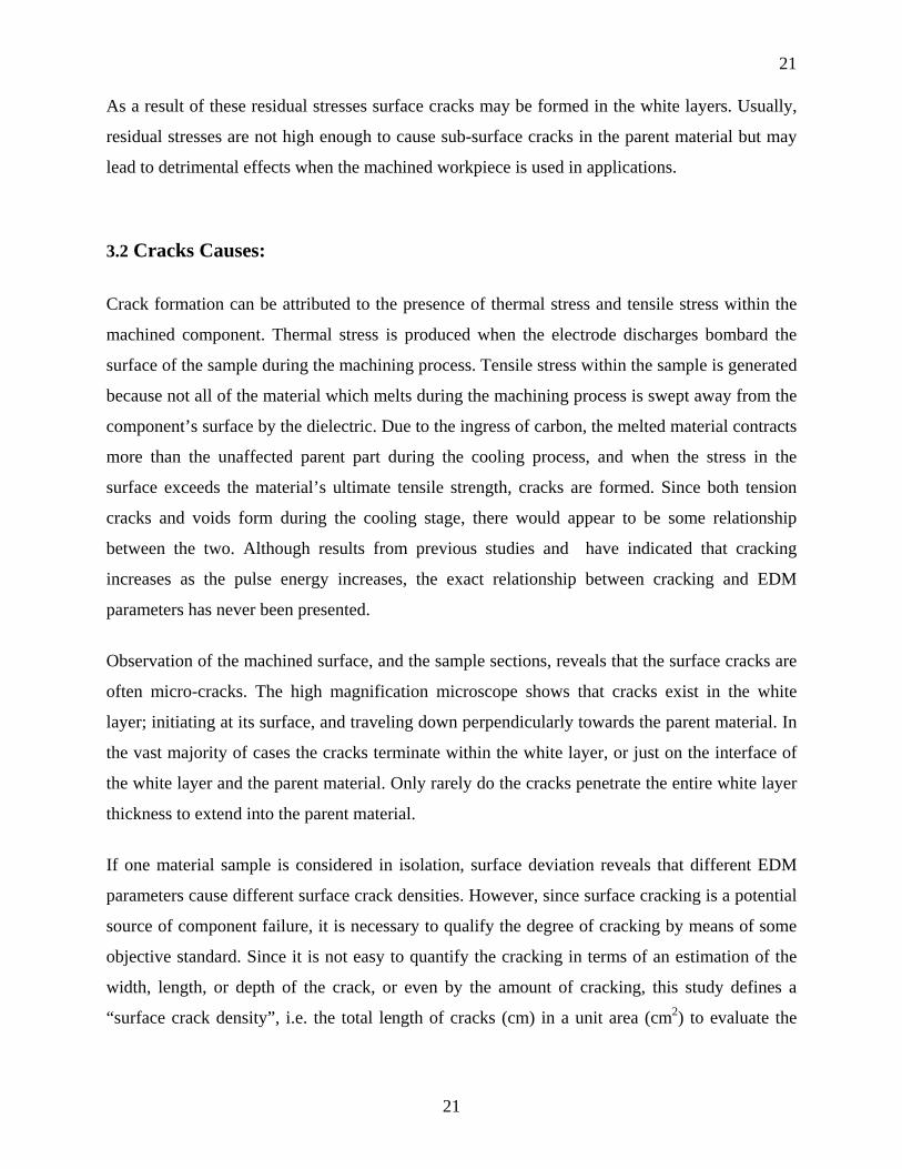
Fig 5.4 SEM photograph of and EDMed surface of En-19 at 45 amp current
Sample 3: Sample No 3 EDMed at a current of 45 amp is the most interesting of the other two samples.In
this sample we observe a drastic change in the microstructure of the sample being EDMed at
such a high current. Craters are visible in the microstructure of this sample machined at 45 amp.
The formation of craters clearly indicate the intensity of stress generated because of the phase
transformed in this sample. At this current the sample while being EDMed bears violent and
subsequent sparks at a short interval. These sparks generate a high heat zone in the fusion region,
transforming the phase of the material from solid to liquid (and even to gas).The liquid metal
quickly re-solidifies and a thin layer known to be white layer is formed because of high current
the temperature developed is much higher which brings about drastic modification in the grain
32

33
structure of the material as seen from the SEM images. Hence the intensity of stress developed is
much higher in the white layer just below the re-solidified layer, giving rise to residual stress
which results in the formation of craters in the sample as seen from the SEM pictures.
5.3 CONCLUSION:
The present work deals with the analysis of residual stresses in EDMed samples which has been
subjected to machining at different currents. The surface characteristics have been studied and
the microstructures observed to conclude the impact of current and pulse on the sample. The
significant findings of the present work are as follows:
1) At low current the surface tends to change less microstructurally. There is little distortion in
the grain structure of the material. Intensity of residual stress developed is less as seen from the
microstructural changes in the sample. At higher current, the surface roughness is more because
of subsequent sparks. The material undergoes a phase transformation from solid to liquid and re-
solidifies very quickly changing the grain structure drastically. Hence it is clear that the
magnitude of stress generated is more at higher current than at lower current.
2) It is a seen that the molten material and material that reached high temperatures tends to
expand. This expansion is impeded by adjacent colder material resulting in significant rise in
compressive stress in the region. Such high stresses lead to localized plastic deformation of the
material. A significant component is the large tensile stress at the surface of the work-piece near
where the plasma arc struck. When molten/heated material cools down it tries to contract but
because it is in contact with the colder region its tendency to contract is impeded to a certain
extent. This results in large tensile residual stresses.
2) Crack formation is related to the EDM parameters. An increased current will increase both the
average white layer thickness and the induced residual stress. These two conditions tend to
promote crack formation. When the pulse current is increased, the increase in material removal
rate causes a high deviation of thickness of the white layer. Compared to a thin white layer, it is
33

34
true to say that a thick white layer has a tendency to crack more readily, however, the area
occupied by the thick layer is less, so the density of surface cracking is broadly similar for both
thin and thick layers.
34

35
REFERENCES :
1] V.P. Aleksandrov, Residual stresses and the long term and fatigue
strengths of heat-resistant materials after electro-spark machining, in:
B.R. Lazarenko (Ed.), Electrospark Machining of Metals, Consultants
Bureau, New York, 1965.
[2] J.R. Crookall, B.C. Khor, Residual stresses and surface effects in
electro discharge machining.
[3] A.G. Mamalis, N.M. Vosniakos, N.M. Vacevanidis, X. Junzhe,
Residual stress distribution and structural phenomena of high-strength
steel surfaces due to EDM and ball-drop forming
[4] J. Wallbank, Effect of EDM on material properties of die steels,
Metallurgia 47 (1) (1980) 356–362.
[5] J.P. Kruth, P. Bleys, Measuring residual stress caused by wire EDM of
tool steel, International Journal of Electrical Machining 5 (1) (2000)
[6] F. Ghanem, C. Braham, H. Sidhom, Influence of steel type on
electrical discharge machined surface integrity, Journal of Materials
Processing Technology 142 (1) (2003) 163–173.
[7] B. Ekmekci, O. Elkoca, A.E. Tekkaya, A. Erden, Residual stress state
35

36
and hardness depth in electric discharge machining: de-ionized water
as dielectric liquid, Machining Science and Technology 9 (1) (2005)
[8] P. Madhu, V.K. Jain,, K.P. Rajurkar, Finite element analysis of EDM
process, Journal of Processing of Advanced Materials 2 (1991) 161–173.
[9] S. Das, M. Klotz, F. Klocke, EDM simulation: finite element-based
calculation of deformation, microstucture and residual stresses,
Journal of Materials Processing Technology 142 (2) (2003) 434–451.
B. Ekmekci et al. / International Journal of Machine Tools & Manufacture 46 (2006) 858–
868 868
[10]J.A. McGeough and H. Rasmussen, A macroscopic model of electro-discharge
machining, International Journal of Machine Tool Design and Research 22 (1982) (4), pp.
333–339.
[11] H. Opitz, Metallurgical aspects and surface characteristics, in: Proceedings of Spark
Machining Symposium, Birmingham, 1960, pp. 237–251.
[12] M. Barash, M.G. Sri-Ram, Some properties of spark machined heat treated steel, in:
Proceedings of 3rd International Machine Tool Design and Research Conference,
Birmingham, 1962, pp. 85–91.
[13] H.K. Lloyd and R.H. Warren, Metallurgy of spark-machined surfaces, Journal of Iron
and Steel Institute 203 (1965) (3), pp. 238–247.
[14] V.P. Aleksandrov, Residual stresses and the long term and fatigue strengths of heat-
resistant materials after electro-spark machining. In: B.R. Lazarenko, Editor, Electrospark
Machining of Metals, Consultants Bureau, New York (1965).
36

37
[15] J.R. Crookall, B.C. Khor, Residual stresses and surface effects in electro discharge
machining, in: Proceedings of 13th International Machine Tool Design and Research
Conference, Birmingham, 1972, pp. 331–338.
[16] W. Koning, R. Wertheim, Y. Zvirin and M. Toren, Material removal and energy
distribution in electrical discharge machining, CIRP Annuals 24 (1975) (1), pp. 95–100.
[17] M.L. Jeswani and S. Basu, Electron microscope study of the deposition and diffusion
of tool material in electrical discharge machining, International Journal of Production
Research 17 (1979) (1), pp. 1–14
[18] A.G. Mamalis, N.M. Vosniakos, N.M. Vacevanidis and X. Junzhe, Residual stress
distribution and structural phenomena of high-strength steel surfaces due to EDM and
ball-drop forming, CIRP Annuals 37 (1988) (1), pp. 531–535.
[19] L.C. Lim, L.C. Lee, Y.S. Wong and H.H. Lu, Solidification microstructure of
electrodischarge machined surfaces of tool steels, Materials Science and Technology 7
(1991) (3), pp. 239–248.
[20] J. Wallbank, Effect of EDM on material properties of die steels, Metallurgia 47 (1980)
(1), pp. 356–362.
[21] J.C. Rebelo, A.M. Diaz, D. Kremer and J.L. Lebrun, Influence of pulse energy on the
surface integrity of martensitic steels, Journal of Materials Processing Technology 84 (1998)
(1–3), pp. 90–96.
[22] J.P. Kruth and P. Bleys, Measuring residual stress caused by wire EDM of tool steel,
International Journal of Electrical Machining 5 (2000) (1), pp. 23–28.
[23] F. Ghanem, C. Braham and H. Sidhom, Influence of steel type on electrical discharge
machined surface integrity, Journal of Materials Processing Technology 142 (2003) (1), pp.
163–173.
37

38
[24] B. Ekmekci, O. Elkoca, A.E. Tekkaya and A. Erden, Residual stress state and
hardness depth in electric discharge machining: de-ionized water as dielectric liquid,
Machining Science and Technology 9 (2005) (1), pp. 39–61.
[25] ASM Handbook Committee, Metals Handbook (eighth ed.), Metallography, Structures
and Phase Diagrams, Metals Park, Ohio 44079, USA vol. 8 (1973) pp. 30–31.
[26] F. Stablein, Spannungsmessungen in eiseiting abgeloschten Knüppeln, Kruppsche
Monatshefte 12 Jahrgang (1931), pp. 93–99.
[27] F.V. Dijck, R. Snoeys, Metal removal and surface layer in electro-discharge
machining, in: Proceedings of International Conference on Production Engineering, Tokyo,
1974, pp. 46–50.
[28] D.D. DiBitonto, P.T. Eubank, M.R. Patel and M.A. Barrufet, Theoretical models of the
electrical discharge machining process. I. A simple cathode erosion model, Journal of
Applied Physics 66 (1989) (9), pp. 4095–4103.
[29] M.R. Patel, M.A. Barrufet, P.T. Eubank and D.D. DiBitonto, Theoretical models of the
electrical discharge machining process. II. The anode erosion model, Journal of Applied
Physics 66 (1989) (9), pp. 4104–4111.
38

39
BIBLOGRAHPY
39