studio reference i - technical · pdf filebecause this amplifier has a high power density, ......
TRANSCRIPT

Operation Manual
Studio Reference I
Obtaining Other Language Versions: To obtain information in another language about the use of this product, please contact your local Crown Distributor. If you need assistance locating your local distributor, please contact Crown at 574-294-8000.
This manual does not include all of the details of design, production, or variations of the equipment. Nor does it cover every possible situation which may arise during installation, operation or maintenance.
The information provided in this manual was deemed accurate as of the publication date. However, updates to this information may have occurred. To obtain the latest version of this manual, please visit the Crown website at www.crownaudio.com.
Trademark Notice: Studio Reference, SmartAmp, Grounded Bridge, PIP2 and PIP are trademarks and Crown, Amcron, IOC, ODEP, and IQ are registered trademarks of Crown International. Other trademarks are the property of their respective owners.
Some models may be exported under the name Amcron.®
©2003 by Crown Audio Inc., P.O. Box 1000, Elkhart, Indiana 46515-1000 U.S.A. Telephone: 574-294-8000
Studio Reference Series
132176-3 5/03
Studio Reference II
®
®

Operation Manual
Studio Reference I & II Professional Studio Amplifiers
page 2
1) Read these instructions.2) Keep these instructions.3) Heed all warnings.4) Follow all instructions.5) Do not use this apparatus near water.6) Clean only with a dry cloth.7) Do not block any ventilation openings. Install
in accordance with the manufacturer’s instruc-tions.
8) Do not install near any heat sources such as radiators, heat registers, stoves, or other apparatus that produce heat.
9) Do not defeat the safety purpose of the polar-ized or grounding-type plug. A polarized plug has two blades with one wider than the other. A grounding-type plug has two blades and a third grounding prong. The wide blade or the third prong is provided for your safety. If the provided plug does not fit into your outlet, consult an electrician for replacement of the obsolete outlet.
10) Protect the power cord from being walked on or pinched, particularly at plugs, convenience receptacles, and the point where they exit from the apparatus.
11) Onlyby th
12) Use ospecappawhento av
13) Unplor wh
14) Refernel. Shas bsuppbeenapparain oor has been dropped.
15) To reduce the risk of fire or electric shock, do not expose this apparatus to rain or moisture.
TO PREVENT ELECTRIC SHOCK DO NOT REMOVE TOP OR BOTTOM COVERS. NO USER SERVICE-ABLE PARTS INSIDE. REFER SERVICING TO QUALIFIED SERVICE PERSONNEL.
À PRÉVENIR LE CHOC ÉLECTRIQUE N’ENLEVEZ PAS LES COUVERCLES. IL N’Y A PAS DES PAR-TIES SERVICEABLE À L’INTÉRIEUR. TOUS REPA-RATIONS DOIT ETRE FAIRE PAR PERSONNEL QUALIFIÉ SEULMENT.
IMPORTANT
Studio Reference Series amplifiers require Class 2 output wiring.
MAGNETIC FIELD
CAUTION! Do not locate sensitive high-gain equip-ment such as preamplifiers or tape decks directly above or below the unit. Because this amplifier has a high power density, it has a strong magnetic field which can induce hum into unshielded devices that are located nearby. The field is strongest just above and below the unit.
Important Safety Instructions
FCC COMPLIANCE NOTICEThis device complies with part 15 of the FCC rules. Operation is subject to the following two conditions: (1) This device may not cause harmful interference, and (2) this device must accept any interference received, including interference that may cause undesired operation.
CAUTION: Changes or modifications not expressly approved by the party responsible for compliance could void the user’s authority to operate the equipment.
NOTE: This equipment has been tested and found to comply with the limits for a Class B digital device, pursuant to part 15 of the FCC Rules. These limits are designed to provide reasonable protection against harmful interference in a residential installation. This equip-ment generates, uses, and can radiate radio frequency energy and, if not installed and used in accordance with the operation manual, may cause harmful interference to radio commu-nications. However, there is no guarantee that interference will not occur in a particular
cause harmful interference to radio or television recep-urning the equipment off and on, the user is encouraged one or more of the following measures:
g antenna. the equipment and receiver.utlet on a circuit different from that to which the receiver
nced radio/TV technician for help.
use attachments/accessories specified e manufacturer.nly with a cart, stand, bracket, or table
ified by the manufacturer, or sold with the ratus. When a cart is used, use caution moving the cart/apparatus combination oid injury from tip-over.ug this apparatus during lightning storms en unused for long periods of time. all servicing to qualified service person-ervicing is required when the apparatus een damaged in any way, such as power-ly cord or plug is damaged, liquid has spilled or objects have fallen into the ratus, the apparatus has been exposed to r moisture, does not operate normally,
If an equipment rack is used, we recommend locat-ing the amplifier(s) in the bottom of the rack and the preamplifier or other sensitive equipment at the top.
WATCH FOR THESE SYMBOLS:
The lightning bolt triangle is used to alert the user to the risk of electric shock.
The exclamation point triangle is used to alert the user to important operating or maintenance instruc-tions.
installation. If this equipment doestion, which can be determined by tto try to correct the interference by
• Reorient or relocate the receivin• Increase the separation between• Connect the equipment into an o
is connected.• Consult the dealer or an experie

page 3
Studio Reference I & II Professional Studio Amplifiers
Operation Manual
DECLARATION of CONFORMITYCrown International, Inc.
European Representative's Name and Address:Nick Owen19 Clos Nant CoslechPontprennauCardiffCF23 8ND United Kingdom
Equipment Type: Commercial Audio Power AmplifiersFamily Name: Studio ReferenceModel Names: Studio Reference I, Studio Reference II
EMC Standards:
EN 55103-1:1995 Electromagnetic Compatibility - Product Family Standard for Audio, Video, Audio-Visual and Entertainment Lighting Control Apparatus for Professional Use, Part 1: Emissions
EN 55103-1:1995 Magnetic Field Emissions-Annex A @ 10 cm and 1 M
EN 61000-3-2:1995+A14:2000 Limits for Harmonic Current Emissions (equipment input current ≤16A per phase)
EN 61000-3-3:1995 Limitation of Voltage Fluctuations and Flicker in Low-Voltage Supply Systems Rated Current ≤16A
EN 55022:1992 + A1: 1995 & A2:1997 Limits and Methods of Measurement of Radio Disturbance Characteristics of ITE: Radiated, Class B Limits; Conducted, Class B
EN 55103-2:1996 Electromagnetic Compatibility - Product Family Standard for Audio, Video, Audio-Visual and Entertainment Lighting Control Apparatus for Professional Use, Part 2: Immunity
EN 61000-4-2:1995 Electrostatic Discharge Immunity (Environment E2-Criteria B, 4k V Contact, 8k V Air Discharge)
EN 61000-4-3:1996 Radiated, Radio-Frequency, Electromagnetic Immunity (Environment E2, criteria A)
EN 61000-4-4:1995 Electrical Fast Transient/Burst Immunity (Criteria B)
EN 61000-4-5:1995 Surge Immunity (Criteria B)
EN 61000-4-6:1996 Immunity to Conducted Disturbances Induced by Radio-Frequency Fields (Criteria A)
EN 61000-4-11:1994 Voltage Dips, Short Interruptions and Voltage Variation
Safety Standard:
EN 60065: 1998 Safety Requirements - Audio Video and Similar Electronic Apparatus
I certify that the product identified above conforms to the requirements of the EMC Council Directive 89/336/EEC as amended by 92/31/EEC, and the Low Voltage Directive 73/23/EES as amended by 93/68/EEC.
Larry Coburn
Signed
Title: Senior Vice President of Manufacturing Date of Issue: January 1, 2000
Issued By: Crown International, Inc. 1718 W. Mishawaka Road Elkhart, Indiana 46517 U.S.A.
DUE TO LINE CURRENT HARMONICS, WE RECOMMEND THAT YOU CONTACT YOUR SUPPLY AUTHORITY BEFORE CONNECTION.

Operation Manual
Studio Reference I & II Professional Studio Amplifiers
page 4
2.8 Startup Procedure ...........................................................12
3 Operation ...................................................13
3.1 Precautions ..................................................................... 13
3.2 Front Panel Controls and Indicators ............................... 15
reaker ....................................................... 19
................................................................ 19
.................................................................. 20
ntrols ....................................................... 20
itches ...................................................... 20
ift Switch ................................................. 21
sitivity Switch ......................................... 21
.................................................................. 21
ration ....................................22
.................................................................. 22
................................................................ 23
peration .................................................... 23
ono Operation ......................................... 23
ono Operation ....................................... 23
............................................24
............................................25
7.1 Mininum Guaranteed Power Specifications .................... 27
7.2 Maximum Power Specifications ..................................... 29
8. AC Power Draw & Thermal Dissipation ................32
9 Service ... .............................................................................. 34
Service .......................................................... 34
nada Service .................................................. 34
ce at a US or Canada Service Center ............. 34
ry Service ...................................................... 34
ry Service Shipping Instructions ................... 34
................................................35
vice Information Form ...................................37
Table of Contents
3.3 Back Panel Controls and Connectors............................... 17
4 Advanced Features and Options .........................18
4.1 Indicators ....................................................................... 18
4.2 Protection Systems ........................................................ 18
4.2.1 ODEP...................................................................... 18
4.2.2 Standby Mode ........................................................ 19
4.2.3 Transformer Thermal Protection ............................. 19
9.1 Worldwide
9.2 US and Ca
9.2.1 Servi
9.2.2 Facto
9.2.3 Facto
10 Warranty ...
Crown Factory Ser
Important Safety Instructions .......................................................2
Declaration of Conformity ............................................................3
1 Welcome ....................................................5
1.1 Features ...........................................................................5
1.2 How to Use This Manual ..................................................6
2 Setup .........................................................7
2.1 Unpack Your Amplifier ....................................................7
2.2 Install Your Amplifier ......................................................7
2.3 Ensure Proper Cooling ...................................................7
2.4 Choose Input Wire and Connectors ................................8
2.5 Choose Output Wire and Connectors ..............................8
2.6 Wire Your System ...........................................................9
2.6.1 Stereo Mode ..........................................................9
2.6.2 Bridge-Mono Mode ...............................................10
2.6.3 Parallel-Mono Mode...............................................11
2.7 Connect to AC Mains ......................................................12
4.2.4 Circuit B
4.3 Filter Cleaning
4.4 Controls .......
4.4.1 Level Co
4.4.2 Meter Sw
4.4.3 Ground L
4.4.4 Input Sen
4.5 PIP Modules .
5 Principles of Ope
5.1 Overview ......
5.2 Circuit Theory
5.2.1 Stereo O
5.2.2 Bridge-M
5.2.3 Parallel-M
6 Troubleshooting
7 Specifications ..

Studio Reference I & II Professional Stu
Operation Manual
ultra-high dynamic range and extraordinary damping factor, your Studio Reference amplifier comes closer to the ideal “straight wire with gain” than any other amplifier. As you listen, it
omplete ase read it , warnings fully install read Sec- one of the
s integrate t make lifiers e each eparate
amplifier because of its separate high-voltage power supplies and ultra-low crosstalk. Here are some of its many impressive features:
• Crown’s unconventional Grounded Bridge™ swings with- configura-lifiers. This on and
Emulation pensates the ampli-
• IOC® (Input/Output Comparator) circuitry immediately alerts you of any distortion that exceeds 0.05% to provide dynamic proof of dis-tortion-free performance.
• PIP™ (Programmable Input Processor) con-nector accepts accessories that tailor your amplifier to suit specific applications.
• Extremely wide dynamic range.
• Ultra-high damping factor delivers superior loudspeaker motion control for the cleanest, tightest bottom end you’ve ever felt—or heard.
• Super-low harmonic and intermodulation dis-tortion give your amplifier the best transfer func-tion in the business.
• Two mono modes (Bridge-Mono and Parallel-Mono) for driving a wide range of load imped-ances.
• Custom-designed, tape-wound, low-noise toroidal supplies with extremely high power den-sity.
• High-voltage headroom and high-current headroom provide energy reserves that make it easy to drive low-impedance loads and highly reactive loads to full power.
• Full protection against shorted outputs, mis-matched loads, general overheating, DC and
will become apparent—the amplifier’s low-fre-quency transient response is the standard by which all others must be judged.
We have taken great care at every step in the cre-ation of your amplifier—from the selection of its components to the routing of each wire. It is our goal to provide you with total satisfaction. This is one reason why we have spent considerable
circuitry delivers incredible voltage out using stressful output transistortions like other more traditional ampresults in significantly lower distortisuperior reliability.
• Patented ODEP® (Output Device Protection) circuitry detects and comfor overheating and overload to keepfier working when others would fail.
1 WelcomeThe stunning realism you will experience when listening to a Crown® Studio Reference™ ampli-fier will redefine your expectations. The evolu-tion of this studio standard ushers in a new era of powerful, ultraquiet amplifiers capable of faithfully reproducing the most demanding of signals. This kind of sonic integrity does not happen accidentally. It demands the leadership and technical excellence for which Crown has long been known.
With the best transfer function in the industry,
effort in providing you with the most cReference Manual in the business. Plecarefully—especially the instructionsand cautions. It will help you successand use your new amplifier. Be sure totions 2.5.2 and 2.5.3 if you plan to useamplifier’s two mono modes.
1.1 Features• Accurate Studio Reference amplifierseveral cutting edge technologies thathem the most accurate reference ampavailable. For example, in Stereo modchannel can actually be treated as a s
dio Amplifiers
®
page 5

Studio Reference I & II Professional Studio Amplifiers
page 6
high-frequency overloads. Full overvoltage and internal fault protection.
• Indicators include Enable, ODEP, IOC, Signal Presence and the Dynamic Range/Level meter.
• Balanced phone jacks and XLR connectors are provided for input. Two pair of 5-way binding posts per channel are provided for versatile out-
• Three year “No-Fault” full warranty com-pletely protects your investment and guarantees its specifications.
1.2 How to Use This ManualThis manual provides you with the necessary information to safely and correctly setup and operate your amplifier. It does not cover every aspect of installation, setup or operation that might occur under every condition. For addi-tional information, please consult Crown’s Amplifier Application Guide (available online at www.crownaudio.com), Crown Technical Sup-port, your system installer or retailer.
We strongly recommend you read all instruc-tions, warnings and cautions contained in this manual. Also, for your protection, please send in your warranty registration card today. And save your bill of sale — it’s your official proof of pur-chase.
1 Welcome
put connection.
• Ground lift switch isolates the AC power and phone jack audio grounds.
• Efficient heat sinks and a self-contained, on-demand, infinitely variable forced-air cooling system prevents overheating and prolongs com-ponent life.
• Internal three-position input sensitivity switch provides settings of 0.775 volts and 1.4 volts for standard 1 kHz power, and 26 dB gain.
• Mounts in a standard 19 inch (48.3 cm) equipment rack, or units can be stacked directly on top of each other.
Operation Manual

page 7
Studio Refe Amplifiers
Operation M
19 in(48.3 cm)
7 in(17.3 cm)
SIDE VIEW
1.4 in(3.6 cm)
®
FRONT VIEW
ur Amplifierinspect your amplifier for y have occurred during found, notify the transpor-ediately. Only you can ini-ping damage. Crown will
needed. Save the shipping carton as evidence of damage for the shipper’s inspection.
We also recommend that you save all packing materials so you will have them if you ever need to transport the unit. Never ship the unit without the factory pack.
d):
r a stable surface
rt to set up you read and fety Instruc-ng of this
the meter . The front panel ed to changed
these switches, so it is easier to do before the unit is mounted (see Section 4.4.2).
The rack ears are covered by two attractive end caps which are held in place by phillips screws (see Figure 2.1). To use the rack ears, remove the screws and lift off the caps. With sufficient side clearance, you can reinstall the end caps
2.2 Install You ierCAUTION: Before in, make sure your amplifier is ected from the power source, w wer switch in the “off” positio level controls turned complete counterclock-wise).
Use a standard 19-inch (48.3 cm) equipment rack (EIA RS-310B). See Figure 2.2 for ampli-fier dimensions.
You may also stack amps without using a cabinet.
NOTE: When transporting, ampli e supported at both front and back
2.3 Ensure Proper CoolingWhen using an equipment rack, mount units directly on top of each other. Close any open spaces in rack with blank panels. DO NOT block front, rear or side air vents. The side walls of the rack should be a minimum of two inches (5.1 cm) away from the amplifier sides, and the back of the rack should be a minimum of four inches (10.2 cm) from the amplifier back panel.
Figure 2.3 illustrates standard amplifier airflow.
2 Setup
Figure 2.3 Airflow
Figure 2.1 REnd
anual
16 in(40.6 cm)
once the amplifier is mounted in the rack.
Figure 2.2 Dimensions
emoving an Cap
YOU WILL NEED (not supplie
• Input wiring cables
• Output wiring cables
Rack for mounting amplifier (ofor stacking)
WARNING: Before you stayour amplifier, make sureobserve the Important Sations found at the beginnimanual.
Before proceeding, make sureswitches are set to your likingassembly must first be remov
rence I & II Professional Studio
2.1 Unpack YoPlease unpack and any damage that matransit. If damage istation company immtiate a claim for shipbe happy to help as
fiers should b.
r Amplif you beg disconnith the pon and allly down (

Operation Manual
Studio Reference I & II Professional Studio Amplifiers
page 8
2.4 Choose Input Wire and ConnectorsCrown recommends using pre-built or professionally wired, bal-anced line (two-conductor plus shield), 22-24 gauge cables and connectors. Use either 3-pin male XLR connectors orTRS phone plugs at the amplifier inputs.
Unbalanced lines may also be used but may result in noise over long cable runs.
Connector pin assignments and wiring are shown in thesFigures:Figure 2.4: Unbalanced XLRFigure 2.5: Balanced XLRFigure 2.6: Balanced and unbalanced phone plugs.
NOTE: Custom wiring should only be performed by qualified personnel.
2 Setup
2.5 Choose Output Wire and ConnectorsCrown recommends using pre-built or professionally wired, high-quality, two-conductor, heavy gauge speaker wire and connectors. You may use banana plugs, spade lugs, or bare wire for your out-put connectors (Figure 2.7). To prevent the possibility of short-circuits, wrap or otherwise insulate exposed loudspeaker cable connectors.
NOTE: Binding post outputs on European models come with safety plugs installed to prevent European power-cord plugs from being inserted. The top & bottom entry positions for these connectors should therefore be used with European models.
Using the guidelines below, select the appropriate size of wire based on the distance from amplifier to speaker.
Distance Wire Size up to 25 ft. 16 AWG 26-40 ft. 14 AWG 41-60 ft. 12 AWG 61-100 ft. 10 AWG 101-150 ft. 8 AWG 151-250 ft. 6 AWG
CAUTION
Figure 2.4 Unbalanced Input Wiring
Figure 2.5 Balanced Input Wiring
Figure 2.6 Balanced and Unbalanced Phone Plugs
Figure 2.7 Output Connector
Wiring
Note: Each output channel has two sets of ake it
ker
: Never use shielded cable for output wiring. binding posts (not shown here) to measier to connect multiple loudspeacables to each channel.

page 9
Studio Reference I & II Professional Studio Amplifiers
Operation M
ReferenceS T U D I O
CH-2 CH-1
PUSH PUSH
FX
MIXER
STUDIO REFERENCEAMPLIFIER
+
–
+
–
CHANNEL 1LOUDSPEAKER
CHANNEL 2LOUDSPEAKER
CHANNEL 1
CHANNEL 2
CAUTION: TURN OFF AMPLIFIER BEFORE CHANGING THIS SWITCH!
STEREOBRIDGEMONO
PARALLELMONO
2.6 Wire Your System
2.6.1 Stereo ModeTypical input and output wiring is shown in Figure 2.8.
Turn off the amplifier and set the Stereo/Mono Switch to Stereo.
INPUTS: Connect input wiring for both channels.
NOTE: Crown provides a reference of wiring pin assignments for commonly used connector types in the Crown Amplifier Application Guide available at www.crownaudio.com.
OUTPUTS: Each output channel has two sets of binding posts to make it easier to connect multi-ple loudspeaker cables to each channel.
Maintain proper polarity (+/–) on output connec-tors.
Connect Channel 1 loudspeaker’s positive (+) lead to Channel 1 positive (red) terminal of amp; repeat for negative (–). Repeat Channel 2 wiring as for Channel 1.
CAUTION: In Stereo mode, never tie an amplifier’s outputs together directly, and never parallel them with the output of another amplifier. Such connections do not result in increased output power, but may activate the protection circuitry to prevent over-heating.
2 Setup
Figure 2.8 Stereo Wiring
anual

Operation Manual
Studio Reference I & II Professional Studio Amplifiers
page 10
ReferenceS T U D I O
CH-2 CH-1
PUSH PUSH
FX
S CEIER
IXER LOUDSPEAKER
–
+
CHANNEL 1
DO NOT USETHE CHANNEL 2
INPUTS.
DO NOT USETHE BLACK
BINDINGPOSTS.
CAUTION: TURN OFF AMPLIFIER BEFORE CHANGING THIS SWITCH!
STEREOBRIDGEMONO
PARALLELMONO
2.6.2 Bridge-Mono ModeBridge-Mono mode is used to drive loads with a total impedance of 4 ohms or higher.
Typical input and output wiring is shown in Figure 2.9.
Turn off the amplifier and set the Stereo/Mono Switch to Bridge Mono.
INPUTS: Use only the Channel 1 input connector.
NOTE: Crown provides a reference of wiring pin assignments for commonly used connector types in the Crown Amplifier Application Guide available at www.crownaudio.
OUTPUTS: Connect the speaker across the red binding post of each channel. Do not use the black binding posts when the amp is being oper-ated in Bridge-Mono mode.
The load MUST be balanced (neither side shorted to ground).
NOTE: The Channel 2 level control MUST be turned down (full CCW) when operat-ing the amplifier in Bridge-Mono mode.
CAUTION: Connect only balanced equip-ment (meters, switches, etc.) to the Bridge-Mono output. Both sides of the line must be isolated from the input ground, or oscillations may occur.
Figure 2.9 Bridge-Mono Wiring
2 Setup
TUDIO REFERENAMPLIF
M
page 11
Studio Reference I & II Professional Studio Amplifiers
Operation M
ReferenceS T U D I O
CH-2 CH-1
PUSH PUSH
FX
TUDIO REFERENCEAMPLIFIER
MIXER LOUDSPEAKER
–
+CHANNEL 1
THE CHANNEL 2INPUTS ARENOT USED
ADD A 14 GAUGEOR LARGER
JUMPER BETWEENTHE CHANNEL 1AND 2 RED (+)
BINDING POSTS
CAUTION: TURN OFF AMPLIFIER BEFORE CHANGING THIS SWITCH!
STEREOBRIDGEMONO
PARALLELMONO
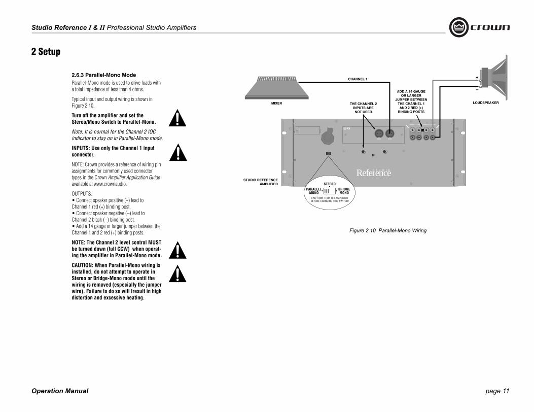
2.6.3 Parallel-Mono ModeParallel-Mono mode is used to drive loads with a total impedance of less than 4 ohms.
Typical input and output wiring is shown in Figure 2.10.
Turn off the amplifier and set the Stereo/Mono Switch to Parallel-Mono.
Note: It is normal for the Channel 2 IOC indicator to stay on in Parallel-Mono mode.
INPUTS: Use only the Channel 1 input connector.
NOTE: Crown provides a reference of wiring pin assignments for commonly used connector types in the Crown Amplifier Application Guide available at www.crownaudio.
OUTPUTS: • Connect speaker positive (+) lead toChannel 1 red (+) binding post. • Connect speaker negative (–) lead to Channel 2 black (–) binding post. • Add a 14 gauge or larger jumper between the Channel 1 and 2 red (+) binding posts.
NOTE: The Channel 2 level control MUST be turned down (full CCW) when operat-ing the amplifier in Parallel-Mono mode.
CAUTION: When Parallel-Mono wiring is installed, do not attempt to operate in Stereo or Bridge-Mono mode until the wiring is removed (especially the jumper wire). Failure to do so will lresult in high distortion and excessive heating.
2 Setup
Figure 2.10 Parallel-Mono Wiring
anual
S

Operation Manual
Studio Reference I & II Professional Studio Amplifiers
page 12
2.7 Connect to AC Mains Connect your amplifier to the AC mains power source (power outlet) with the supplied AC power cordset. First, connect the IEC end of the cordset to the IEC connector on the amplifier; then, plug the other end of the cordset to the AC mains.
2.8 Startup ProcedureUse the following procedure when first turning on your amplifier:
1. Turn down the level of your audio source.
2. Turn down the level controls of the amplifier.
3. Turn on the “Enable” switch. The Enable indi-cator should glow.
4. Turn up the level of your audio source to an optimum level.
5. Turn up the Level controls on the amplifier until the desired loudness or power level is achieved.
6. Turn down the level of your audio source to its normal range.
If you ever need to make any wiring or installation changes, don’t forget to disconnect the power cord.
For help with determining your system’s optimum gain structure (signal levels) please refer to the Crown Amplifier Application Guide, available online at www.crownaudio.com.
2 Setup
WARNING: The third prong of this connector (ground) is an important safety feature. Do not attempt to disable this ground connec-tion by using an adapter or other methods.
Amplifiers don’t create energy. The AC mains volt-age and current must be sufficient to deliver the power you expect. You must operate your amplifier from an AC mains power source with not more than a 10% variation above or a 15% variation below the amplifier’s specified line voltage and within the specfied frequency requirements (indicated on the amplifier’s back panel label). If you are unsure of the output voltage of your AC mains, please consult your electrician.
page 13
Studio Reference I & II Professional Studio Amplifiers
Operation M
3.1 PrecautionsYour amplifier is protected from internal and exter-nal faults, but you should still take the following precautions for optimum performance and safety:
1. Before use, your amplifier first must be config-ured for proper operation, including input and
3 Operation
4. WARNING: Never connect the output to a power supply, battery or power main. Electrical shock may result.
5. Tampering with the circuitry, or making unau-thorized circuit changes may be hazardous and invalidates all agency listings.
6. Do not operate the amplifier with the red Clip LEDs constantly flashing.
7. Do not overdrive the mixer, which will cause clipped signal to be sent to the amplifier. Such signals will be reproduced with extreme accu-racy, and loudspeaker damage may result.
8. Do not operate the amplifier with less than the rated load impedance. Due to the amplifier’s output protection, such a configuration may result in premature clipping and speaker dam-age.
Remember: Crown is not liable for damage that results from overdriving other system components.
anual
output wiring hookup. Improper wiring can result in serious operating difficulties. For information on wiring and configuration, please consult the Setup section of this manual or, for advanced setup techniques, consult Crown’s Amplifier Application Guide available online at www.crownaudio.com.
2. Use care when making connections, selecting signal sources and controlling the output level. The load you save may be your own!
3. Do not short the ground lead of an output cable to the input signal ground. This may form a ground loop and cause oscillations.

Studio Reference I & II Professional Studio Amplifiers
page 14
®
G H
A B C D ABCD E F
3 Operation
Figure 3.1 Front Panel Controls and Indicators
Operation Manual
page 15
Studio Reference I & II Professional Studio Amplifiers
Operation M
3.2 Front Panel Controls
limits the output drive so the amplifier can safely continue operating even under severe conditions. These indicators also help to iden-tify more unusual operating conditions (see Figure 4.1).
C. IOC Indicators
Under normal conditions, the indicators remain utput waveform differs
5% or more (see put signal level is too ill also flash brightly with lay to show input over-g. Note: The channel 2
n in Parallel-Mono mode.
e Indicators
synchronously with the ut to show signal pres-icators may not flash at
levels. See Section 4.1.
r
This indicator lights when the amplifier has been “enabled” or turned on, and AC power is available.
F. Enable Switch
This push button is used to turn the amplifier turned on, the output is our seconds to protect your -up transients. This is why a
power sequencer is rarely needed for multiple units. (The turn-on delay can be changed. Con-tact Crown’s Technical Support Group for details.)
G. Dust Filter
The dust filter removes large particles from the air drawn in by the cooling fan. In most cases, the fan will not run so the filter will remain clean. If the filter becomes dirty, it can be removed for easy cleaning (see Section 4.3).
H. Dynamic Range/Level Meters
A five-segment output meter is provided for each channel. The meters are factory-set to show dynamic range of the signals in dB, which is computed as the ratio of peak to average out-put power. Also, the meter can optionally be set to show output levels (see Section 4.1).
• Meter Switches
Two switches behind the front panel can be used to customize the output meters (H). By default, the meters display dynamic range. To make the meters display signal levels or to turn them off, see Section 4.4.2.
3 Operation
anual
The IOC (Input Output Comparator) indicators serve as sensitive distortion indicators to pro-vide proof of distortion-free performance.
on and off. Whenmuted for about fsystem from start
and Indicators
A. Level Controls
Each channel’s output level can be adjusted accurately using the 31-position detented level controls on the front panel (see Section 4.4.1).
B. ODEP Indicators
During normal operation of the amplifier, the ODEP (Output Device Emulation Protection) indicators glow brightly to show the presence of reserve thermodynamic energy. They dim proportionally as energy reserves decrease. In the rare event that energy reserves are depleted, the indicators turn off and ODEP proportionally
off. They flash if the ofrom the input by 0.0Section 4.2). If the inhigh, the indicators wa half-second hold deload or output clippinIOC indicator stays oSee Section 4.1.
D. Signal Presenc
These indicators flashamplifier’s audio outpence. Note: These indvery low input signal
E. Enable Indicato

Studio Reference I & II Professional Studio Amplifiers
page 16
Figure 3.2 Back Panel Connectors and Controls
3 Operation
Operation Manual
page 17
Studio Reference I & II Professional Studio Amplifiers
Operation M
3.3 Back Panel Connectors and
K. PIP Module
The standard P.I.P.-FX input module is provided with your amplifier. It provides female XLR input connectors. Each pair of XLR and phone jack connectors is wired in parallel so the unused connector can be used as a “daisy
L. Balanced XLR Inputs
ale XLR connector is (K) for input to each ot use the her mono mode.
ay binding posts are each channel so mul- connected easily. , spade lugs or bare
h
ect one of three oper-e is used for normal
two-channel operation, Bridge-Mono mode is used to drive a single channel with a load impedance of at least 4 ohms, and Parallel-Mono mode is used to drive a single channel with a load impedance of less than 4 ohms. WARNING: Turn off the amplifier before
s switch (see Sections 2.5.1, 3).
O. Balanced Phone Jack Inputs
A balanced 1/4-inch phone jack is provided for input to each channel. They may be used with either balanced (tip, ring and sleeve) or unbal-anced (tip and sleeve) input wiring (see Section 3.3). These inputs are in parallel with the PIP connector, so they should not be used as inputs if the installed PIP has active circuitry.Caution: Do not use the channel 2 input in either mono mode.
P. Ground Lift Switch
The input signal ground may be isolated from the AC ground with this switch to help prevent unwanted ground loops. It affects only the phone jacks (O). It has no effect on the PIP module’s XLR connectors. Activating the switch inserts an impedance between the sleeve of each phone input jack and the circuit ground. See Section 4.4.3.
• Input Sensitivity Switch
The three-position input sensitivity switch inside the amplifier can be accessed by remov-ing the PIP module. Settings include 0.775 volts and 1.4 volts for rated output, and 26 dB voltage gain (see Section 4.4.4).
3 Operation
anual
chain” output to connect a source to multiple amplifiers. Other PIP modules can be used in place of the P.I.P. -FX to provide additional fea-tures that customize your amplifier for different applications (see Section 4.5).
changing thi2.5.2 and 2.5.
Controls
I. Reset Switch
This back panel switch can be used to trip and reset the AC mains circuit breaker (see Section 4.2.4).
J. Power Cord
For 120 VAC, 60 Hz North American units, the Studio Reference I includes a 10 AWG power cord and NEMA TT30P plug, and the Studio Reference II includes a 12 AWG cord and NEMA 5-15P plug. Other units are shipped with an appropriate power cord and plug.
A balanced three-pin femprovided on the P.I.P.-FX channel. Caution: Do nChannel 2 input in eit
M. Output Connectors
Two pairs of versatile 5-wprovided for the output oftiple loudspeakers can beThey accept banana plugswire.
N. Stereo/Mono Switc
This switch is used to selating modes. Stereo mod

Operation Manual
Studio Reference I & II Professional Studio Amplifiers
page 18
age supplies.
The green ODEP indicators confirm the normal operation of Crown’s patented Output Device Emu-lation Protection circuitry. During normal operation, they glow brightly to confirm the presence of
voltage is detected. For more information see Sec-tion 4.2 and Chapter 6 on Troubleshooting.
4 Advancedand Options
act as sensitive distor-of distortion-free/Output Comparator) ing signal’s waveform rence between the two ors flash if there is a The IOC indicators flashing brightly with a ormal for them to light ier is first turned on.
Note: The channel 2 IOC indicator will stay on in Parallel-Mono mode. Also, an IOC indicator will stay on in abnormal situations where a high-voltage power supply is temporarily put in standby mode.
The green signal presence indicators flash syn-amplifier’s output signal. The nected to the signal path after
and level controls, so a flash-u that there is audio in and out : The signal presence indica-ignal presence if the output .
e/level meters are five-seg-hat can be set to monitor either r the level of the output signal. to show dynamic range. A d the front panel is used to lay mode (see Section 4.4.2 for s). As dynamic range meters nel’s ratio of peak-to-average amic range may be low for
sources like AM/FM radio or low-quality record-
ings. Other sources like live music or high-quality recordings may be much higher. As output level meters they show how high the output levels are in dB relative to full power. At 0 dB, the unit is deliver-ing full standard 1 kHz power (see Section 7).
4.2 Protection SystemsStudio Reference amplifiers provide extensive pro-tection and diagnostics capabilities. Protection sys-tems include ODEP, standby mode, an AC circuit breaker and transformer thermal protection. These systems will prevent amplifier damage in virtually any situation.
4.2.1 ODEPCrown invented ODEP to solve two long-standing problems in amplifier design: to prevent amplifier shutdown during demanding operation and to increase the efficiency of output circuitry.
To do this, Crown established a rigorous program to measure the safe operating area (SOA) of each out-put transistor before installing it in an amplifier. Next, Crown designed intelligent circuitry to simu-late the instantaneous operating conditions of the output transistors. Its name describes what it does: Output Device Emulation Protection or ODEP. In addition to simulating the operating conditions of the output transistors, it also compares their opera-tion to their known SOA. If ODEP sees that more power is about to be asked of the output transistors than they are capable of delivering under the present conditions, ODEP immediately limits the drive level until it falls within the SOA. Limiting is proportional and kept to an absolute minimum—only what is required to prevent output transistor damage.
Figure 4.1 Indicators
reserve thermodynamic energy. They dim propor-tionally as the energy reserve decreases. In the rare event that there is no reserve, the indicators will turn off and ODEP will proportionally limit the drive level of the output stages so the amplifier can continue safe operation even when the operating conditions are severe. (For a more detailed description of ODEP, see Section 4.2.1.)
A channel’s ODEP indicator also turns off if its high-voltage power supply if it is put in “standby” mode or the amplifier’s circuit breaker is tripped. The standby mode is activated if DC or heavy common-mode current is detected in the output, if the trans-former thermal protection system is activated, if a PIP with SmartAmp™ features is used to shut down a high-voltage supply, or if excessive AC mains
chronously with the signal detector is conthe input gain stagesing indicator tells yoof the amplifier. Notetors may not report ssignal level is too low
The dynamic rangment output meters tthe dynamic range oThey are factory-set switch located behinselect the meter dispcomplete instructionthey show each chanpower in dB. The dyn
4.1 IndicatorsThe front panel has several helpful indicators. The enable indicator is provided to show the ampli-fier has been turned on (or enabled) and that its low-voltage power supply and on-demand forced air cooling system are working. It does not indicate the status of the high-voltage power supplies. For example, the enable indicator will stay on in the improbable event that one or both channels over-heat causing an internal shut down of the high volt-
Features
The yellow IOC indicators tion meters to provide proof performance. The IOC (Inputcircuitry compares the incomto that of the output. Any diffeis distortion. The IOC indicatdifference of 0.05% or more.also show input overload by half-second hold delay. It is nmomentarily when the amplif

page 19
Studio Refe
Operation M
4 Advanceand Optio
control the amplifier.
This is how ODEP keeps the show going with maxi-mum power and maximum protection at all times.
4.2.2 Standby Mode
will put both channels into standby when excessive AC mains voltage is detected. Studio Reference amplifiers should not be operated with an AC mains voltage of more than 10% over the unit’s rated volt-age.
tions where heavy common-mode current is detected in the channel’s output. The amplifier should never output heavy common-mode current unless its circuitry is damaged in some way, and putting the channel into standby mode helps to pre-vent further damage.
to the high-voltage power supplies if it detects excessive heat. The switch automatically resets itself as soon as the transformer cools to a safe tem-perature.
If your amplifier is operated within rated conditions,
in the transformer than in the output devices. This can overheat the transformer and activate its protec-tion system.
Studio Reference amplifiers are designed to keep working under conditions where other amplifiers would fail. But even when the limits of a Studio Ref-erence amplifier are exceeded, it still protects itself—and your investment—from damage.
4.2.4 Circuit BreakerA back panel circuit breaker is provided to prevent excessive current draw by the high-voltage power supplies. A Studio Reference I configured for 100 to 120 VAC has a 30 amp circuit breaker, while the 220 to 240 VAC version has a 20 amp circuit breaker. A Studio Reference II configured for 100 to 120 VAC uses a 20 amp circuit breaker, and the 220 to 240 VAC version has a 10 amp circuit breaker. With rated loads and output levels, this breaker should only trip in the incredibly rare instance of a cata-strophic amplifier failure. The ODEP system keeps the amplifier safe and operational under most other severe conditions. The breaker can also trip in situ-ations where extremely low-impedance loads and high output levels result in current draw that exceeds the breaker’s rating. Again, this should only be possible when operating outside rated condi-tions, like when the amplifier is used to drive a 1 ohm load, or when an input signal is clipped severely.
4.3 Filter CleaningA dust filter is provided on the amplifier’s air intake (see Figure 3.1). If this filter becomes clogged, the unit will not cool as efficiently as it should and high heat sink temperatures may produce lower-than-normal output.
Dust filters are not 100% efficient—depending on the local environment, the internal heat sinks of the amplifier will benefit from periodic cleaning by a qualified technician. Internal cleaning information is available from our Technical Support Group.
anual
If dangerous subsonic frequencies or direct current (DC) is detected in the amplifier’s output, the unit will activate its DC/low-frequency protection circuitry and put the affected channels in standby. This protects the loads and prevents oscillations. The amplifier resumes normal operation as soon as
it is extremely unlikely that you will ever see it acti-vate transformer thermal protection. One reason is that ODEP keeps the amplifier working under very severe conditions. Even so, higher than rated output levels, excessively low-impedance loads and unrea-sonably high input signals can generate more heat
An important part of a Studio Reference amplifier’s protection systems is standby mode. Standby pro-tects the amplifier during potentially catastrophic conditions. It temporarily removes power from the high-voltage supplies to protect the amplifier and its loads. Standby mode can be identified using the Troubleshooting chart in Chapter 6.
Standby mode is activated in five situations. First, when you turn on the enable switch, standby mode is activated to provide turn-on protection. This power-up delay lets other system components settle before any signals are amplified and it provides some power-up “randomness” for multiple units so the system’s start-up current demands are better distributed over time.
The amplifier’s overvoltage protection circuitry
The amplifier’s transformer thermal protection circuitry is activated in very unusual circumstances where the unit’s transformer temperature rises to unsafe levels. Under these abnormal conditions, the amplifier will put both channels into standby mode. The amplifier will return to normal operation after the transformer cools to a safe temperature. (For more information on transformer thermal protection, refer to the section that follows.)
4.2.3 Transformer Thermal ProtectionAll Studio Reference amplifiers have transformer thermal protection which protects the power sup-plies from damage under rare conditions where the transformer temperature rises too high. A thermal switch embedded in the transformer removes power
rence I & II Professional Studio Amplifiers
d Features ns
This level of protection enables Crown to increase output efficiency to never-before-achieved levels while greatly increasing amplifier reliability.
The on-board intelligence is monitored two ways. First, the amplifier’s ODEP indicators show whether the unit is functioning correctly or if ODEP is limit-ing output. Second, ODEP data is fed to the ampli-fier’s internal PIP connector so advanced PIP modules like the IQ-PIP can use it to monitor and
it no longer detects dangerous low-frequency or DC output. Although it is extremely unlikely that you will ever activate the amplifier’s DC/low-frequency protection system, improper source materials such as subsonic square waves or input overloads that result in excessively clipped signals can activate this system.
The amplifier’s fault protection system will put an amplifier channel into standby mode in rare situa-

Operation Manual
Studio Reference I & II Professional Studio Amplifiers
page 20
(FRONT
To remove the handle,pull firmly from the side.
®
METER ON/OFF SWITCONOFF
DYNAMIC RANGEOUTPUT LEVEL
METER MODE SWITCH
4 Advancedand Options
n.
nt n
modes for the meters, or you can turn the meters off. From the factory, the meters auto-matically display dynamic range (which is computed as the ratio of peak to average output
power). To change these switches, you will need to remove part of the front panel. A phil-lips screwdriver will be needed, and it will help to remove the amplifier if it is mounted in a rack. Follow these steps:
1. Make sure the amplifier is turned off and its power cord is disconnected from the AC mains source.
2. Remove the two screws that hold each end cap in place and remove both end caps (see Figure 2.1).
3. Remove the six screws that hold each handle in place and remove each handle (see Figure 4.2).
4. Remove the dust filter by gently pulling it away from the front panel.
5. Remove the two screws that secure the lower half of the front panel and remove the lower front panel.
6. Locate the meter switches as shown in Figure 4.3. Set the switches as desired. The left switch is used to turn the meters on and off, and the right switch is used to change display modes.
7. Reassemble the front panel, handles and end caps in reverse order of disassembly.
8. Install the amplifier and reconnect power.
Figure 4.3 Meter Switches
H
Figure 4.2 Removing a Handle
AMPLIFIER TOP VIEW LEFT CORNER—END CAP REMOVED)
Features
4.4 Controls
4.4.1 Level ControlsEach of the front panel level controls has 31 detents for accurately repeatable settings. In Bridge-Mono and Parallel-Mono modes, thechannel 2 level control should be turned dow
4.4.2 Meter SwitchesThe meter switches are located behind the fropanel. They make it possible to switch betweethe dynamic range and signal level display

Studio Reference I & II Professional Studio Amplifiers
Operation M
4 Advanceand Option
4.4 Input Sensitivity and Ground Lift Switches
ever, pin 1 of the XLR is not connected in parallel with the sleeve of the phone jack. This makes it pos-sible for a PIP module to handle its own signal grounds independently.
The amplifier’s circuit breaker protects the power
the power supplies, or to the right to reconnect power. If the circuit breaker trips, the front panel enable indicator will turn off. If this occurs, turn off the enable switch, flip the reset switch to the right (on), and then turn the enable switch back on. If it trips again or the amplifier does not operate prop-erly, contact an authorized service center or Crown’s Technical Support Group.
4.4.4 Input Sensitivity SwitchThe input sensitivity switch is located inside the amplifier’s PIP compartment. It is factory-set to a fixed voltage gain of 26 dB. For standard 1 kHz power into 8 ohms, this is equivalent to an input sensitivity of 4.0 volts for the Studio Reference I and 2.7 volts for the Studio Reference II. If needed, it can be switched to a sensitivity of 0.775 or 1.4 volts. Here is the procedure:
1. Turn off the amplifier and disconnect the power cord from the receptacle.
2. Remove the PIP module.
3. Locate the access hole for the sensitivity switch inside the chassis opening (see Figure 4.4).
4. Set the switch to the desired position noted on the access hole label.
5. Replace the PIP module and restore power.
4.5 PIP ModulesVersatile PIP (Programmable Input Processor) and PIP2 modules provide flexible expansion features that can be added to customize the amplifier. The modules plug into the connector inside the back panel of the amplifier. The modules are available
ith features ranging from error-driven compres-ors/limiters to crossovers to IQ® control. Visit the rown website at www.crownaudio.com, or contact rown Customer Service, for descriptions of avail-ble PIP and PIP2 modules.
wsCCa
page 21
anualFigure
supplies from overload. The breaker’s reset switch is located on the back panel. Facing the back panel, move the reset switch the left to disconnect power to
d Features s
4.4.3 Ground Lift SwitchThe ground lift switch located on the back panel can provide isolation between the phone jack input grounds and the AC (chassis) ground. It does not affect the PIP module’s input connectors. Slide the switch to the left to isolate or “lift” the grounds.
Note: The noninverted and inverted signal lines for the PIP module are connected in parallel with the corresponding lines of the phone jack inputs. The input signal grounds are not paralleled. Specifically, XLR pins 2 and 3 are connected in parallel with the tip and ring of the corresponding phone jack. How-

Operation Manual
Studio Reference I & II Professional Studio Amplifiers
page 22
FAULT
NLY ONE CHANNEL SHOWN
NPN HIOUTPUTSTAGE
NPN LOWOUTPUTSTAGE
PNP LOWOUTPUTSTAGE
PNP HIOUTPUTSTAGE
+
OUTPUT
+Vcc
–Vcc
TRANSLATOR LVA
–Vcc
CURRENTLIMITBALANCED
INPUTS
1/4" PHONE
XLR
DISPLAY
BIAS
BRIDGEBALANCE
+Vcc
–Vcc
POWERSUPPLY
CONTROLDC/LF
TIMERPOWER
+Vcc
–Vcc
A(ODEP)
B(ODEP)
SUPPLY
DE
(DISPLAY)D
(DISPLAY)E
HSTEMP
C(ODEP)
+24
–24
ENABLE
OVERVOLTAGE
5 Principles
mon hazards that plague high-power amplifiers including shorted, open or mismatched loads; overloaded power supplies, excessive temperature, chain-destruction phe-
(hereafter referred to as the output devices). Current is lim-ited only when the device temperature becomes exces-sive—and only by the minimum amount necessary. This patented approach maximizes the available output power and eliminates overheating—the major cause of device failure.
Crown also invented the four-quadrant topology used in the output stages of each Studio Reference amplifier (see Figure 5.1). This special circuitry is called the grounded bridge. It makes full use of the power supply by delivering peak-to-peak voltages to the load that are twice the voltage seen by the output devices.
As its name suggests, the grounded bridge topology is ref-erenced to ground. Composite devices are constructed to function as gigantic NPN and PNP devices to handle cur-
ts which exceed the limits of available devices. Each tput stage has two composite NPN and two composite P devices.
e devices connected to the load are referred to as “high-e NPN and PNP” and the devices connected to ground
are referred to as “low-side NPN and PNP.” Positive cur-rent is delivered to the load by increasing conductance simultaneously in the high-side NPN and low-side PNP stage, while synchronously decreasing conductance of the high-side PNP and low-side NPN.
The two channels may be used together to double the volt-age (Bridge-Mono) or the current (Parallel-Mono) pre-sented to the load. This feature gives you the flexibility to maximize power available to the load.
A wide bandwidth, multiloop design is used for state-of-the-art compensation. This produces ideal behavior and results in ultra-low distortion values.
Aluminum extrusions are used widely for heat sinks in power amplifiers due to their low cost and reasonable per-formance. However, measured on a watts per pound or watts per volume basis, the extrusion technology doesn’t perform nearly as well as the heat sink technology devel-oped for Studio Reference amplifiers.
Figure 5.1 Circuit Block Diagram
O
LVA
+Vcc
BIAS
TRANSLATOR
BALANCEINPUT STAGE
P.I.P.
VARIABLEGAIN STAGE
ERRORAMP
ODEPABC
nomena, input overload and high-frequency blowups. The unit protects loudspeakers from input and output DC, as well as turn-on and turn-off transients.
Real-time computer simulation is used to create an ana-logue of the junction temperature of the output transistors
renouPN Thsid
of Operation
5.1 OverviewStudio Reference amplifiers incorporate several new tech-nological advancements including real-time computer simulation of output transistor stress, low-stress output stages, an advanced heat sink embodiment and the Pro-grammable Input Processor (PIP) expansion system.
Custom circuitry is incorporated to limit temperature and current to safe levels making it highly reliable and tolerant of faults. Unlike many lesser amplifiers, it can operate at its voltage and current limits without self-destructing.
Studio Reference amplifiers are protected against all com-

page 23
Studio Reference I & II Professional Studio Amplifiers
Operation M
through D4, D22 and D24) and filtered by large computer grade capacitors. A thermal switch embedded in the trans-former protects it from overheating. Monolithic regulators
voltage-translator stage.
From the error amp, the voltage translator stage channels the signal to the Last Voltage Amplifiers (LVAs) depending on the signal polarity. The +LVA (Q104 and Q105) and the
stage. This results in the Vcc supply having exactly one half of the output voltage added to its quiescent voltage. Bias servo Q300 sets the quiescent current point for the bridge-balanced output stage.
exceed the safe operating area of the output stage.Thermal sensor S100 gives the ODEP circuit vital informa-tion on the operating temperature of the heat sink on which the output devices are mounted.Should the amplifier fail in such a way that would cause
5.2.2 Bridge-Mono OperationBy setting the back panel stereo/mono switch to Bridge-Mono, the user can convert the amplifier into a bridged, single-channel amplifier. With a signal applied to the channel 1 input jack and the load connected across the two channels’ red (+) 5-way binding posts, twice the volt-age can be output.
The channel 1 output feeds the channel 2 error amp U204-C. Because there is a net inversion, channel 2 output is out of polarity with channel 1. This produces twice as much voltage across the load. Each channel’s protection mecha-nisms work independently if a fault occurs.
5.2.3 Parallel-Mono OperationWith the stereo/mono switch set to Parallel-Mono, the out-put of channel 2 is paralleled with the output of channel 1. A suitable jumper capable of handling high current must be connected across the red (+) 5-way posts to gain the benefits of this mode of operation.
The signal path for channel 1 is the same as previously discussed, except channel 1 also drives the output stage of channel 2. The channel 2 balanced input, error amp, trans-lators and LVAs are disconnected and no longer control the channel 2 output stage. Disconnecting the front-end stages from the channel 2 output causes the channel 2 IOC circuit to note that the input waveform (which is not present) does not match the output waveform (which is driven by the channel 1 input signal). This activates the channel 2 IOC indicator any time the amplifier is switched into Parallel-Mono mode. The channel 2 output stage and protection mechanisms are also coupled through S1 and function as one.
In Parallel-Mono mode, twice the current of one channel alone can be obtained. Because the channel 2 ODEP cir-cuit is coupled through S1, this gives added protection if a fault occurs in the channel 2 output stage. The ODEP cir-cuit of channel 2 will limit the output of both output stages by removing the drive from the channel 1 translator stages.
5 Princip
anual
–LVA (Q110 and Q111) drive the fully complementary out-put stage with their push-pull effect through the bias servo Q318.
DC across the output leads, the DC/low-frequency protec-tion circuit senses this on the negative feedback loop and shuts down the power supply until the DC is removed.
provide a regulated ±15 volts.
5.2.1 Stereo OperationFor simplicity, the discussion of Stereo operation will refer to only one channel. Mono operation will be discussed later. Please refer to the block diagram in Figure 5.1.
The input signal at the phone jack passes directly into the balanced gain stage (U104-A). When a PIP module is used, the input signal first passes through the PIP ’s cir-cuitry and then to the balanced gain stage.
The balanced gain stage (U104-A) causes balanced to sin-gle-ended conversion using a difference amplifier. From there, gain can be controlled with the front panel level con-trols and the input sensitivity switch. The error amp (U104-C) amplifies the difference between the output sig-nal and the input signal from the gain pot, and drives the
The protection mechanisms that affect the signal path are implemented to protect the amplifier under real-world con-ditions. These conditions are high instantaneous current, excessive temperature, and output device operation out-side safe conditions.
Q107 and Q108 act as a conventional current limiter, sens-ing current in the output stage. When output current at any instant exceeds the design criteria, the limiters remove drive from the LVAs, thus limiting current in the output stage to a safe level.
To further protect the output stages, the patented ODEP circuitry is used. It produces an analog output propor-tional to the always changing safe operating area of the output transistors. This output controls the translator stage previously mentioned, removing any further drive that may
Our heat sinks are fabricated from custom convoluted fin stock that provides an extremely high ratio of area to vol-ume, or area to weight. All power devices are mounted directly to the heat sinks which are also electrically at the Vcc potential. Electrifying the heat sinks improves thermal performance by eliminating the insulating interface under-neath the power devices. The chassis itself is even used as part of the thermal circuit to maximize utilization of the available cooling resources.
5.2 Circuit TheoryPower is provided by low-field toroidal power transformer T1. The secondaries of T1 are full-wave rectified (by D1
The bias servo Q318 is thermally coupled to the heat sink, and sets the quiescent bias current in the output stage to lower the distortion in the crossover region of the output signal.With the voltage swing provided by the LVAs, the signal then gains current amplification through the triple Darling-ton emitter-follower output stage.
The bridge-balanced circuit (U104-D) receives a signal from the output of the amplifier, and differences it with the signal at the Vcc supply. The bridge-balanced circuit then develops a voltage to drive the bridge-balanced output
les of Operation

Operation Manual
Studio Reference I & II Professional Studio Amplifiers
page 24
6 Troubleshooting
page 25
Studio Reference I & II Professional Studio Amplifiers
Oper
ce I Studio Reference II
555W355W
1,100W715W
1,115W710W
ce I Studio Reference II
26 dB gain 0.775V, 1.4 V, or 26 dB gain
± 0.1 dB
+5° to –15°
> 117 dB
< 0.1%
% at 78 milliwatts< 0.005% rising linearly to 0.025% at 36 milliwatts
> 20,000> 2,500
> 100 dB> 65 dB
7 Specifications
ation Manual
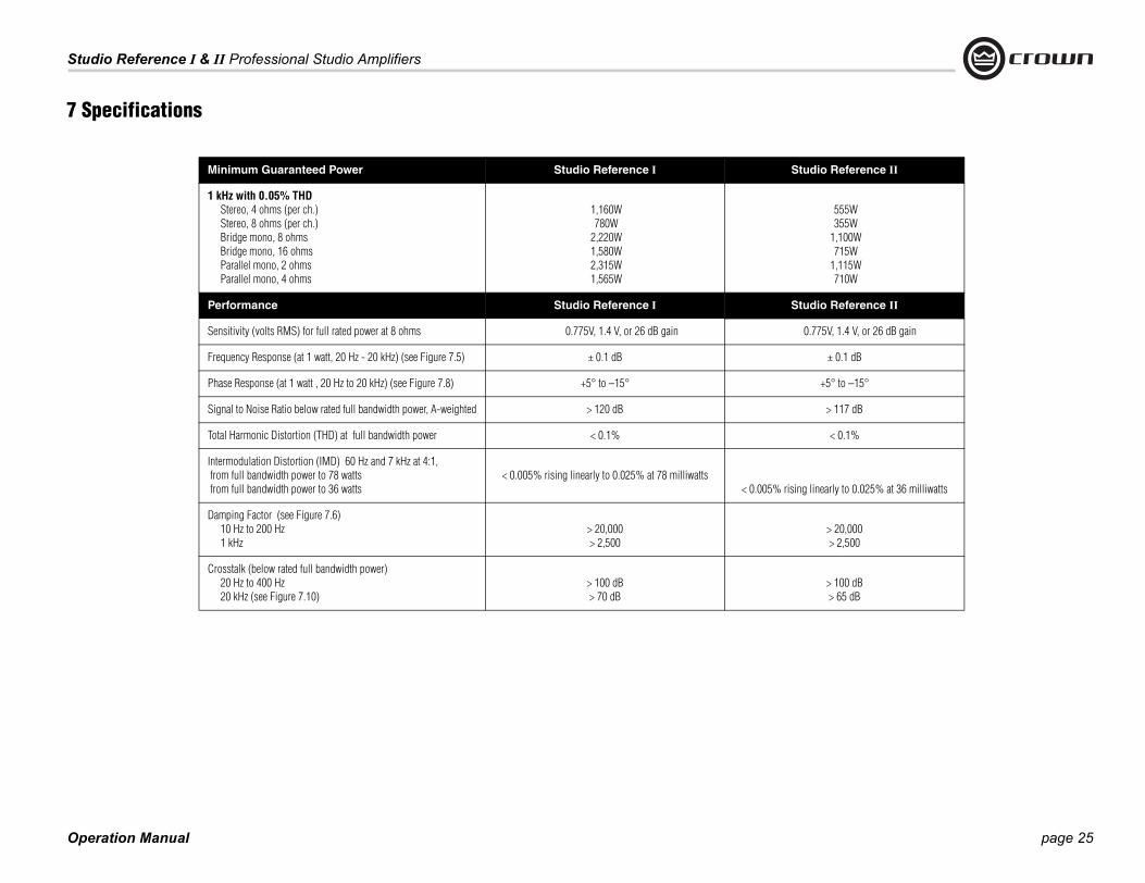
Minimum Guaranteed Power Studio Referen
1 kHz with 0.05% THD Stereo, 4 ohms (per ch.) Stereo, 8 ohms (per ch.) Bridge mono, 8 ohms Bridge mono, 16 ohms Parallel mono, 2 ohms Parallel mono, 4 ohms
1,160W780W
2,220W1,580W2,315W1,565W
Performance Studio Referen
Sensitivity (volts RMS) for full rated power at 8 ohms 0.775V, 1.4 V, or
Frequency Response (at 1 watt, 20 Hz - 20 kHz) (see Figure 7.5) ± 0.1 dB
Phase Response (at 1 watt , 20 Hz to 20 kHz) (see Figure 7.8) +5° to –15°
Signal to Noise Ratio below rated full bandwidth power, A-weighted > 120 dB
Total Harmonic Distortion (THD) at full bandwidth power < 0.1%
Intermodulation Distortion (IMD) 60 Hz and 7 kHz at 4:1, from full bandwidth power to 78 watts from full bandwidth power to 36 watts
< 0.005% rising linearly to 0.025
Damping Factor (see Figure 7.6) 10 Hz to 200 Hz 1 kHz
> 20,000> 2,500
Crosstalk (below rated full bandwidth power) 20 Hz to 400 Hz 20 kHz (see Figure 7.10)
> 100 dB> 70 dB

Operation Manual
Studio Reference I & II Professional Studio Amplifiers
page 26
Studio Reference II
10 kilohms, 5 kilohms
4-8 ohms8-16 ohms2-4 ohms
:1 ± 6% or 37 dB ± 0.5 dB at 0.775-volt sensitivity8:1 ± 6% or 32 dB ± 0.5 dB at 1.4-volt sensitivity
20:1 ± 6% at 26 dB gain ± 0.5 dB
< 10 milliohms in series with 2.5 microhenries
± 2 millivolts
or 60 Hz; 100, 120, 200, 220 or 240 VAC (± 10%)
90W
Studio Reference II
Flow-through ventilation from front to sides
On-demand proportional speed fan
Standard 19-inch rack mount width (EIA RS-310B), nch (17.8-cm) height and 16-inch (40.6-cm) depth ind mounting surface and 2.75 inch (7 cm) protru-
sion in front of mounting surface
56.1 pounds (25.5 kg)69.6 pounds (31.6 kg)
7 Specifications
Performance Studio Reference I
Input Impedance (nominally balanced, nominally unbalanced) 10 kilohms, 5 kilohms
Load Impedance (Note: Safe with all types of loads) Stereo Bridge Mono Parallel Mono
4-8 ohms8-16 ohms2-4 ohms
Voltage Gain (at maximum level setting) 103:1 ± 6% or 40 dB ±0.5 dB at 0.775-volt sensitivity57:1 ± 6% or 35 dB ± 0.5 dB at 1.4-volt sensitivity
20:1 ± 6% at 26 dB gain ± 0.5 dB
693
Output Impedance < 10 milliohms in series with 2.5 microhenries
DC Output Offset (shorted input) ± 2 millivolts
AC Line Voltage and Frequency Configurations Available (± 10%) 50 or 60 Hz; 100, 120, 200, 220 or 240 VAC (± 10%) 50
Power draw at idle 90W
Construction Studio Reference I
Ventilation Flow-through ventilation from front to sides
Cooling On-demand proportional speed fan
Dimensions EIA Standard 19-inch rack mount width (EIA RS-310B), 7-inch (17.8-cm) height and 16-inch (40.6-cm) depth behind mounting surface and 2.75 inch (7 cm) protru-
sion in front of mounting surface
EIA7-ibeh
Weight Net Shipping
60.7 pounds (27.6 kg)74.2 pounds (33.7 kg)

page 27
Studio Reference I & II Professional Studio Amplifiers
Operation M
7 Specific
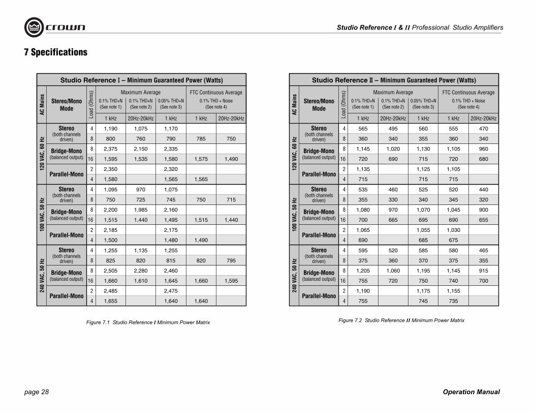
smallest amount of output power you can expect from your amplifier when it is driven to full out-put under the given conditions. Some spaces in each matrix may be left blank because the same guarantee is not provided for those conditions—however, your amplifier will perform well under all conditions listed in each matrix.
ach on-HD is
ower ions tion real
Many manufacturers publish power specs with a tolerance of ±1 dB or worse. This means their amplifier can deviate more than 20% in output! A 100 watt amplifier would meet their specification if it only produced 79.4 watts. Other manufactur-ers qualify their specs by saying they are “typi-cal,” “subject to manufacturing tolerances,” “single channel driven” or that they are specified with “fuses bypassed.” Each of these statements
performance guarantee. rers use these tactics to mbers, and they don’t
e take a different r amplifiers are guaran-eir specifications for ou should get what you
Minimum Power Notes:All minimum power specifications are based on 0.5% regulated AC mains with THD of less than 1.0% and an ambient room temperature of 70° F (21° C). Standard EIA power (RS-490) is not shown here because it is identical to FTC Con-tinuous Average Power.
1. A 1 kHz sine wave is presented to the amplifier and the output monitored for nonlinear distor-tion. The level is increased until THD reaches 0.1%. At this point, average power per channel is reported.
2. A sine wave is presented to the amplifier over the range from 20 Hz to 20 kHz and the output monitored for nonlinear distortion. The level at each frequency is increased until THD reaches 0.1%. At this point, average power per channel is reported.
3. A 1 kHz sine wave is presented to the amplifier and the output monitored for nonlinear distor-tion. The level is increased until THD reaches 0.05%. At this point, average power per channel is reported.
4. Continuous power in the context of Federal Trade Commission testing is understood to be a minimum of five minutes of operation. Harmonic distortion is measured as the RMS sum total and given as a percentage of the fundamental output voltage. This applies for all wattages greater than 0.25 watts.
anual
When measuring power, 0.1% THD appears to be the industry standard for distortion. Two of the maximum average power specifications shown in each minimum power matrix are mea-sured at 0.1% THD so you can easily compare Crown specifications to those of other manufac-turers. But this high level of distortion actually allows for some clipping which is undesirable. Because of this, a maximum average power
effectively removes any In fact, some manufactugenerate large power nueven print a disclaimer. Wapproach at Crown—outeed to meet or exceed ththree years. We believe ypay for.
ations
Crown specifications are guaranteed for three years.
In an effort to provide you with as much informa-tion as possible about the high power-producing capabilities of your amplifier, we have created the following power matrices.
7.1 Minimum Guaranteed Power SpecificationsShown in Figures 7.1 and 7.2, Crown’s mini-mum power specifications represent the absolute
specification at 0.05% THD is included in eminimum power matrix which represents nclipped conditions. Also, power at 0.02% Tprovided in the preceding specifications. Although most manufacturers do not give pspecifications at 0.05% or 0.02% THD, weencourage them to provide these specificatso you will have a more realistic representaof the way amplifiers should be used in theworld—without a clipped output signal.
Operation Manual
Studio Reference I & II Professional Studio Amplifiers
page 28
Figure 7.1 Studio Reference I Minimum Power Matrix Figure 7.2 Studio Reference II Minimum Power Matrix
7 Specifications

page 29
Studio Reference I & II Professional Studio Amplifiers
Operation M
7 Specifications
7.2 Maximum Power SpecificationsShown in Figures 7.3 and 7.4, Crown’s maxi-mum power specifications represent the largest amount of output power you can expect from your amplifier when it is driven to full output under the given conditions. These specifications can be used to prevent loudspeaker and hearing damage.
The maximum power matrices include specifica-tions for single cycle and 40 millisecond burst sine waves. Burst signals act like large transient peaks that are present in common source sig-nals. Loudspeakers can respond to a single cycle burst, so the single cycle burst specifica-tions should be used to help you protect your loudspeakers. In contrast, a 40 millisecond burst represents the typical response time of the human ear. Your ear will not respond to the entire dynamic change of a burst that lasts less than 40 milliseconds.
The burst power specifications are provided at 0.05% THD which is a practical low distortion condition. Operating the amplifier at levels higher than 0.05% THD can result in output power levels that are higher than those listed in the maximum power matrices.
Maximum Power Notes:All maximum power specifications are based on 0.5% regulated AC mains with THD of less than 1.0% and an ambient room temperature of 70° F (21° C). Although it is an unusual condition, your amplifier can function well with AC mains voltages up to 10% over the specified line volt-age. With overvoltage conditions, your amplifier may be capable of delivering instantaneous power levels up to 20% greater than the specifi-cations in the matrix.
1. A single cycle sine wave is presented to the amplifier and monitored for nonlinear distortion. The average power during the burst is reported. Loudspeakers must be able to withstand this level if they are to be safely used with this ampli-fier.
2. A 40 millisecond sine wave burst (10 percent duty cycle) is presented to the amplifier and monitored for nonlinear distortion. Average power during the burst is reported. This power level is a measurement of the amplifier’s maxi-mum transient power that can be perceived by the human ear.
Figure 7.3 Studio Reference I Maximum Power Matrix
anual

Operation Manual
Studio Reference I & II Professional Studio Amplifiers
page 30
10 100 1 K 10 K 100 K
FREQUENCY (Hz)
+2
+1
0
–1
–2
–3
–4
dB
–5
–6
–7
4 ohm
8 ohm
1 watt
DAMPING
0 100 1 K 10 K 20 K
100
1,000
10,000
100,000
FREQUENCY (Hz)
8 ohm
7 Specifications
Figure 7.4 Studio Reference II Maximum Power Matrix
Figure 7.5 Typical Frequency Response
Figure 7.6 Typical Damping Factor
210

page 31
Studio Reference I & II Professional Studio Amplifiers
Operation Manual
OHMS
0.001
0.0001
0.01
0.1
1
20 100 1 K 10 K 20 K
FREQUENCY (Hz)
8 ohm
+45˚
+90˚
+135˚
0˚
–45˚
–90˚
–135˚10020 1 K 10 K 20 K
FREQUENCY (Hz)
0
–60dB
–40
–20
–80
–100
–12010020 1 K 10 K 20 K
FREQUENCY (Hz)
0
–60dB
–40
–20
–80
–100
–12010020 1 K 10 K 20 K
FREQUENCY (Hz)
Studio Reference II
Studio Reference I
7 Specifications
Figure 7.7 Typical Output Impedance
Figure 7.8 Typical Phase Response
Figure 7.9 Typical Common Mode Rejec re 7.10 Typical Crosstalk
tion Figu
Operation Manual
Studio Reference I & II Professional Studio Amplifiers
page 32
This section provides detailed information about the amount of power and current drawn from the AC mains by Studio Reference amplifiers and the amount of heat produced under various conditions. The calcula-tions presented here are intended to provide a realistic and reliable depiction of the amplifiers. The following assumptions or approxima-tions were made:
• The amplifier’s available channels are loaded, and full standard 1 kHz power is being delivered.
• Amplifier efficiency at standard 1 kHz power is estimated to be 65%.
• Quiescent power draw is 90 watts (an almost negligible amount for full-power calculations).
• Quiescent thermal dissipation equals 307 btu/hr at 90 watts.
• The estimated duty cycles take into account the typical crest factor for each type of source material.
• Duty cycle of pink noise is 50%.
• Duty cycle of highly compressed rock ‘n’ roll midrange is 40%.
• Duty cycle of rock ‘n’ roll is 30%.
• Duty cycle of background music is 20%.
• Duty cycle of continuous speech is 10%.
• Duty cycle of infrequent, short duration paging is 1%.
Here are the equations used to calculate the data presented in Figures 8.1 and 8.2:
The estimated quiescent power draw of 90 watts is a maximum figure, and assumes that the fan is running at high speed. The following equa-tion converts power draw in watts to current draw in amperes:
The power factor of 0.83 is needed to compensate for the difference in phase between the AC mains voltage and current. The following equa-tion is used to calculate thermal dissipation:-
The constant 0.35 is inefficiency (1.00–0.65) and the factor 3.415 con-verts watts to btu/hr. Thermal dissipation in btu is divided by the con-stant 3.968 to get kcal. If you plan to measure output power under real-world conditions, the following equation may also be helpful:
8 AC Power Draw andThermal Dissipation

Studio Reference I & II Professional Studio Amplifiers
Operation Manual
8 Ohm Stereo / 16 Ohm Bridge-Mono / 4 Ohm Parallel-Mono
L O A D
50%
40%
30%
20%
10%
1325
1075
830
585
340
1,780
1,485
1,190
900
605
1,925
1,555
1,190
825
460
630
520
410
300
190
15.9
12.9
10.0
7.0
4.1
23.1
18.7
14.3
9.9
5.5
DutyCycle
AC MainsPowerDraw
(Watts) btu/hr
Current Draw (Amps)
7.2
5.9
4.5
3.2
1.8
10.5
8.5
6.5
4.5
2.5
4 Ohm Stereo / 8 Ohm Bridge-Mono / 2 Ohm Parallel-Mono
Studio Reference I
450
375
300
230
155
kcal/hr
2,500
2,060
1,620
1,185
745
100-120 V 220-240 V
Thermal Dissipation
btu/hr
Current Draw (Amps)
kcal/hr100-120 V 220-240 V
Thermal DissipationAC MainsPowerDraw
(Watts)
o / 16 Ohm Bridge-Mono / 4 Ohm Parallel-Mono
L O A D
50%
40%
30%
20%
10%
970
840
705
575
440
975
795
620
445
270
345
290
240
185
135
7.8
6.4
5.1
3.8
2.4
11.7
9.6
7.5
5.3
3.2
DutyCycle btu/hr
Current Draw (Amps)
3.5
2.9
2.3
1.7
1.1
5.3
4.4
3.4
2.4
1.5
4 Ohm Stereo / 8 Ohm Bridge-M arallel-Mono
Studio Reference II
245
215
180
145
115
kcal/hr100-120 V 220-240 V
Thermal Dissipation Current Draw (Am
kcal/hr100-120 V 220-24
l DissipationAC MainsPowerDraw
(Watts)
Figure 8.1 Studio Reference I Power Draw, Current Draw and Thermal Dissipation at Various Duty Cycles
gure 8.2 Studio Reference II Power Draw, Current Draw Thermal Dissipation at Various Duty Cycles
8 Ohm Stere
645
535
425
315
205
AC MainsPowerDraw
(Watts)
Fi
ono / 2 Ohm P
1,360
1,150
940
730
520
btu/hr
ps)
0 V
Therma
and
page 33

Operation Manual
Studio Reference I & II Professional Studio Amplifiers
page 34
CAUTION: To prevent electric shock, do not remove covers. No user serviceable parts inside. Refer servicing to a quali-fied technician.
9.1 Worldwide ServiceService may be obtained from an authorized
that you have your copy of the bill of sale as your proof of purchase.
9.2.1 Service at a US or Canada Service CenterThis method usually saves the most time and effort. Simply present your bill of sale along
chase and the defective unit to the Crown factory.
For warranty service, we will pay for ground shipping both ways in the United States. Con-tact Crown Customer Service to obtain pre-paid shipping labels prior to sending the unit.
2. Be sure to fill out the service information form that follows and enclose it with your shipment, either inside the box or in a packing slip envelope securely attached to the outside of the shipping carton. Do not send the service information form sepa-rately. If you are sending the unit from a
3. To ensure the safe transportation of your unit to the factory, ship it in an original factory packing container. If you don’t have the original carton, you may obtain a prod-uct service foam-in-place shipping pack from the Crown Factory Service Depart-ment at the number listed below. For non-warranty service, you may also provide your own shipping pack, however we still recommend using a Crown Supplied Ship-ping Container. Minimum recommended requirements for materials are as follows: 275 P.S.I. burst test Double-Wall carton that allows for 2-inch solid Styrofoam on all six sides of unit or 3 inches of plastic bubble wrap on all six sides of unit; securely seal the package with an adequate carton sealing tape. Do not use light boxes or “peanuts.” Damage caused by poor packing cannot be covered under warranty.
4. Do not ship the unit in any kind of cabinet (wood or metal). Ignoring this warning may result in extensive damage to the unit and the cabinet. Accessories are not needed—do not send the product docu-mentation, cables and other hardware.
If you have any questions, please contact Crown Factory Service.
Crown Factory Service 1718 W. Mishawaka Rd.,
Elkhart, Indiana 46517 U.S.A.
Telephone: 574-294-8200800-342-6939 (North America,
Puerto Rico, and Virgin Islands only)
Facsimile: 574-294-8301 (Technical Support)574-294-8124 (Factory Service)
Internet: http://www.crownaudio.com
9 Service
with the defective unit to an authorized service center to obtain service. They will handle the necessary paperwork and repair. Remember to transport the unit in the original factory pack. A
Shipping Center, we recommend taping the form to the product. We also recom-mend recording the serial number and model before shipping for your reference.
service center. (Contact your local Crown/Amcron representative or our office for a list of authorized service centers.) To obtain service, simply present the bill of sale as proof of pur-chase along with the defective unit to an autho-rized service center. They will handle the necessary paperwork and repair.
Remember to transport your unit in the original factory pack.
9.2 US and Canada ServiceService may be obtained in one of two ways: from an authorized service center or from the factory. You may choose either. It is important
Or, if you prefer, you may prepay the cost of shipping, and Crown will reimburse you. Send copies of the shipping receipts to Crown to receive reimbursement.
Your repaired unit will be returned via UPS ground. Please contact us if other arrange-ments are required.
9.2.3 Factory Service Shipping Instructions:1. Before sending a Crown product to the
factory for service, first call the Crown Ser-vice Department for a return authorization (RA) number.
Crown amplifiers are quality units that rarely require servicing. Before returning your unit for servicing, please contact Crown Technical Sup-port to verify the need for servicing.
This unit has very sophisticated circuitry which should only be serviced by a fully trained tech-nician. This is one reason why each unit bears the following label:
list of authorized service centers in your area can be obtained from the Crown website at www.crownaudio.com, or by calling Crown Customer Service.
9.2.2 Factory ServiceTo obtain factory service, fill out the service information page found in the back of this man-ual and send it along with your proof of pur-

page 35
Studio Reference I & II Professional Studio Amplifiers
Operation M
YEAR3SUMMARY OF WARRANTY
Crown International, 1718 West Mishawaka Road, Elkhart, Indiana 46517-4095 U.S.A. warrants to you, the ORIGINAL PURCHASER and ANY SUB-SEQUENT OWNER of each NEW Crown product, for a period of three (3) years from the date of
est, insurance, closing costs, and other finance charges less a reasonable depreciation on the product from the date of original purchase. War-ranty work can only be performed at our autho-rized service centers or at the factory. Warranty work for some products can only be performed at
FROM ANY DEFECT IN THE NEW CROWN PRODUCT. THIS INCLUDES ANY DAMAGE TO ANOTHER PRODUCT OR PRODUCTS RESULT-ING FROM SUCH A DEFECT. SOME STATES DO NOT ALLOW THE EXCLUSION OR LIMITATIONS OF INCIDENTAL OR CONSEQUENTIAL DAM-
MITATION OR EXCLU-O YOU.
ATIONS
ty to enlarge, amend, or ty. This Crown War-
he length of time which e of the new Crown acement parts provided own Warranty shall ortion of this Crown
ange the design of any without notice and with responding changes in factured.
OF PURCHASER
GIVES YOU SPECIFIC Y ALSO HAVE OTHER OM STATE TO STATE. rown Warranty shall be
on of the warranty
RRANTY SUPERSEDES D IN THIS MANUAL . 12/01
10 WarrantyUNITED STATES & CANADA
anual
purchase by the original purchaser (the “warranty period”) that the new Crown product is free of defects in materials and workmanship. We further warrant the new Crown product regardless of the reason for failure, except as excluded in this War-ranty.
ITEMS EXCLUDED FROM THIS CROWN WARRANTY
This Crown Warranty is in effect only for failure of a new Crown product which occurred within the Warranty Period. It does not cover any product which has been damaged because of any inten-tional misuse, accident, negligence, or loss which is covered under any of your insurance contracts. This Crown Warranty also does not extend to the new Crown product if the serial number has been defaced, altered, or removed.
WHAT THE WARRANTOR WILL DO
We will remedy any defect, regardless of the rea-son for failure (except as excluded), by repair, replacement, or refund. We may not elect refund unless you agree, or unless we are unable to pro-vide replacement, and repair is not practical or cannot be timely made. If a refund is elected, then you must make the defective or malfunctioning product available to us free and clear of all liens or other encumbrances. The refund will be equal to the actual purchase price, not including inter-
our factory. We will remedy the defect and ship the product from the service center or our factory within a reasonable time after receipt of the defec-tive product at our authorized service center or our factory. All expenses in remedying the defect, including surface shipping costs in the United States, will be borne by us. (You must bear the expense of shipping the product between any for-eign country and the port of entry in the United States including the return shipment, and all taxes, duties, and other customs fees for such for-eign shipments.)
HOW TO OBTAIN WARRANTY SERVICE
You must notify us of your need for warranty ser-vice within the warranty period. All components must be shipped in a factory pack, which, if needed, may be obtained from us free of charge. Corrective action will be taken within a reason-able time of the date of receipt of the defective product by us or our authorized service center. If the repairs made by us or our authorized service center are not satisfactory, notify us or our autho-rized service center immediately.
DISCLAIMER OF CONSEQUENTIAL AND INCIDENTAL DAMAGES
YOU ARE NOT ENTITLED TO RECOVER FROM US ANY INCIDENTAL DAMAGES RESULTING
AGES, SO THE ABOVE LISION MAY NOT APPLY T
WARRANTY ALTER
No person has the authorimodify this Crown Warranranty is not extended by tyou are deprived of the usproduct. Repairs and replunder the terms of this Crcarry only the unexpired pWarranty.
DESIGN CHANGES
We reserve the right to chproduct from time to timeno obligation to make corproducts previously manu
LEGAL REMEDIES
THIS CROWN WARRANTYLEGAL RIGHTS, YOU MARIGHTS WHICH VARY FRNo action to enforce this Ccommenced after expiratiperiod.
THIS STATEMENT OF WAANY OTHERS CONTAINEFOR CROWN PRODUCTS

Operation Manual
Studio Reference I & II Professional Studio Amplifiers
page 36
YEAR3
10 WarrantyWORLDWIDE EXCEPT USA & CANADA
SUMMARY OF WARRANTY
Crown International, 1718 West Mishawaka Road, Elkhart, Indiana 46517-4095 U.S.A. warrants to you, the ORIGINAL PURCHASER and ANY SUB-
We will remedy any defect, regardless of the rea-son for failure (except as excluded), by repair, replacement, or refund. We may not elect refund unless you agree, or unless we are unable to pro-vide replacement, and repair is not practical or
d is elected, then malfunctioning clear of all liens nd will be equal
t including inter-d other finance ciation on the l purchase. War-d at our autho-
medy the defect ervice center ceipt of the defec-rvice center.
Y SERVICE
n importer of ce within the warranty t be shipped in the
on will be taken within e of receipt of the orized service center.
uthorized service cen-y our authorized ser-
DISCLAIMER OF CONSEQUENTIAL AND INCIDENTAL DAMAGES
YOU ARE NOT ENTITLED TO RECOVER FROM US ANY INCIDENTAL DAMAGES RESULTING FROM ANY DEFECT IN THE NEW CROWN PRODUCT. THIS INCLUDES ANY DAMAGE TO ANOTHER PRODUCT OR PRODUCTS RESULTING FROM SUCH A DEFECT.
WARRANTY ALTERATIONS
No person has the authority to enlarge, amend, or modify this Crown Warranty. This Crown Warranty is not extended by the length of time which you are deprived of the use of the new Crown product. Repairs and replacement parts provided under the terms of this Crown Warranty shall carry only the unexpired portion of this Crown Warranty.
DESIGN CHANGES
We reserve the right to change the design of any product from time to time without notice and with no obligation to make corresponding changes in products previously manufactured.
LEGAL REMEDIES OF PURCHASER
No action to enforce this Crown Warranty shall be commenced after expiration of the warranty period.
THIS STATEMENT OF WARRANTY SUPERSEDES ANY OTHERS CONTAINED IN THIS MANUAL FOR CROWN PRODUCTS. 7/01
which has been damaged because of any inten-tional misuse, accident, negligence, or loss which is covered under any of your insurance contracts. This Crown Warranty also does not extend to the new Crown product if the serial number has been defaced, altered, or removed.
WHAT THE WARRANTOR WILL DO
You must notify your local Cyour need for warranty serviperiod. All components musoriginal box. Corrective actia reasonable time of the datdefective product by our authIf the repairs made by our ater are not satisfactory, notifvice center immediately.
SEQUENT OWNER of each NEW Crown1 product, for a period of three (3) years from the date of pur-chase by the original purchaser (the “warranty period”) that the new Crown product is free of defects in materials and workmanship, and we further warrant the new Crown product regardless of the reason for failure, except as excluded in this Warranty.
1 Note: If your unit bears the name “Amcron,” please substitute it for the name “Crown” in this warranty.
ITEMS EXCLUDED FROM THIS CROWN-WARRANTY
This Crown Warranty is in effect only for failure of a new Crown product which occurred within the Warranty Period. It does not cover any product
cannot be timely made. If a refunyou must make the defective or product available to us free andor other encumbrances. The refuto the actual purchase price, noest, insurance, closing costs, ancharges less a reasonable depreproduct from the date of originaranty work can only be performerized service centers. We will reand ship the product from the swithin a reasonable time after retive product at our authorized se
HOW TO OBTAIN WARRANT
row

page 37
Studio Reference I & II Professional Studio Amplifiers
Operation Manual
Crown Factory Service InformationShipping Address: Crown Factory Service, 1718 W. Mishawaka Rd., Elkhart, IN 46517
Phone: 1-800-342-6939 or 1-574-294-8200 Fax: 1-574-294-8124
Owner’s Name : ________________________________________________________________________________________________________________________________________________________________
Shipping Address: ______________________________________________________________________________________________________________________________________________________________
Phone Number: ________________________________Fax Number: ________________________________ Email ________________________________________________________________________________
Model: __________________________________________________________________________________ Serial Number: ________________________________________________________________________
Purchase Date : ________________________________________________________________________________________________________________________________________________________________
NATURE OF PROBLEM
(Be sure to describe the conditions that existed when the problem occurred and what attempts were made to correct it.)
______________________________________________________________________________________________________________________________________________________________________________
______________________________________________________________________________________________________________________________________________________________________________
______________________________________________________________________________________________________________________________________________________________________________
______________________________________________________________________________________________________________________________________________________________________________
______________________________________________________________________________________________________________________________________________________________________________
______________________________________________________________________________________________________________________________________________________________________________
______________________________________________________________________________________________________________________________________________________________________________
______________________________________________________________________________________________________________________________________________________________________________
Other equipment in system: ___________________________________________________________________________________________________________________________________________________________
______________________________________________________________________________________________________________________________________________________________________________
______________________________________________________________________________________________________________________________________________________________________________
______________________________________________________________________________________________________________________________________________________________________________
If warranty has expired, payment will be: ! Cash/Check ! Visa ! Master Card ! C.O.D. ! Purchase Order for Crown Dealer
Card Number:___________________________________ Exp. Date:___________________
Signature:______________________________________________________________________
ENCLOSE THIS PORTION WITH THE UNIT. DO NOT MAIL SEPARATELY.

THIS PAGE INTENTIONALLY LEFT BLANK

NOTES