studio air, semester 2, 2013 - bhargav sridhar
DESCRIPTION
This document presents my studio work across a period of 12 weeks, exhibiting research into digital design methodology and parametric modelling, observing precedent works, employing an iterative design approach through digital modelling and fabrication, while providing a suitable design solution to a brief as directed by the Studio Requirements. The project features a Gateway design for Wyndham City, Victoria.TRANSCRIPT

B H A R G A V S R I D H A R
S e m e s t e r 2 , 2 0 1 3
AIRS T U D I O
5 8 5 5 9 1

Acknowledgements
Tutor: David ListerGroupmates: Rovi Lau and Xiaofan Wang
Contact Me
Email: [email protected]

C O N T E N T S1
3
5
7
11
13
15
17
21
23
25
29
31
35
36
37
39
41
45
49
59
61
69
73
77
79
83
87
91
93
95
97
107
111
119
123
133
139
141
143
145
Introduction
Past Experience
Part A - Expression of Interest I : A Case for Innovation
A.1: Architecture as a Discourse
Source of Identif ication
Precedent Project: Barcaldine Tree of Knowledge
Precedent Project: Metropol Parasol
A.2: Computation in Architecture
Precedent Project: Smithsonian Institution
Precedent Project: ICD/ITKE Research Pavil ion 2010
A.3: Parametric Modell ing
Precedent Project: People’s Meeting Dome
Precedent Project: The Almond Pavil ion, SG2012 Gridshell
A.4: Conclusion
A.5: Learning Outcomes
A.6: Appendix - Algorithmic Explorations
Part B - Expression of Interest II : An Approach to Design
B.1.1: Design Focus
B.1.2: Design Approach
B.2: Case Study 1.0
B.3.1: Case Study 2.0: Hexigloo Pavil ion
B.3.2: Reverse Engineering
B.3.3: Prototyping
B.4.1: Technique: Development
B.4.2: Technique: Form Finding
B.4.3: Technique: Final Outcome
B.5: Technique: Tectonic Prototyping
B.6: Technique Proposal
B.7: Learning Outcomes
B.8: Appendix - Technique Algorithm
Part C - Project Proposal: Establishing Wyndham’s Identity
C.1: Design Concept
C.2.1: Tectonic Elements - Kerfing
C2.2: Construction Documentation and Model
C.3.1: Final Model: Assembly
C.3.2: Final Model: Result
C.3.3: Project Conclusion
C.4: Learning Objectives
C.5: Algorithmic Sketches
Images
Notes

1

2
Approaching 20 years of age, I am
an undergraduate student working
on completing my second year of
the Bachelor of Environments at the
University of Melbourne.
I n t r o d u c t i o n

3
Pre v i o u s E x p l o r a t i o n s
In 2012, I opted to take the subject, Virtual Environments during my first semester of the Environments Degree.
The subject introduced a new method of approaching design, which featured a prominent inspiration
derived from natural processes which is then developed further using modelling tools such as Rhinoceros
and reproduced in the physical form of a paper lantern. The challenging experiences undergone as a result
of this project pushed me to reach past my limitations as I was made aware of how to conceptualise design
ideas beyond the literal expressions extracted from nature in order to obtain a totally unique outcome
of design; one that depicts the rationale through the immateriality rather than the physical features.
Above: Wearable paper lantern project, Virtual Environments 2012.

4
Over the course of the 12 weeks, I received valuable
knowledge as I took my first steps into the world of
parametric architecture and modern fabrication
technology. The introduction of Rhinoceros 3D
and the Paneling tools plugin formed the basis of
the design of the wearable paper lantern. Due to
the challenging technical obstacles, I progressed
through a grueling experience of going back and
forth in the design process adjusting and simplifying
the design to achieve a realistic outcome by
the given deadline. This undertaking provided
me with a significant understanding of how a
designer in modern days is only limited by his/her
own knowledge and their skills in applying their
ideas efficiently using the available technology.
The introduction to fabrication techniques
using machinery such as laser and card cutters
created a new awareness in my mind for the
possibilities of producing physical forms of complex
geometry with great accuracy. Presentation
skills were also emphasised due to its importance
in the design process. I found my graphical
skills improve rapidly through the course of the
subject which is a crucial feature of any designer.

5
Part A - Expression of Interest I :A Case for Innovation

6
Good Design Is a Renaissance attitude that combines
technology, cognitive science, human need, and beauty to
produce something that the world didn’t know it was missing.
“ “ - Paola Antonelli

A.1
Ar c h i t e c t u r e a s a Di s c o u r s e

8
For a significantly large period of time the understanding of architecture was primarily
focused upon physical elements of building design and construction. From the time of
Vitruvius’ De Architectura, which classified architecture with fixed boundaries, through the
vast classical era, across the Baroque and the time of Renaissance, there existed a universal
understanding that architecture referred to that of the built world and the architect performs
the role of a master builder or craftsman1. Even today, a similar perception of architecture as
a collection of solid, tangible, constructed objects in the public realm is considered by some2.
However, according to Richard Williams, the last couple of decades has seen the
growing desire of government authoritative figures to commission the reformation
of the public realm by implementing the use of architecture3. This I believe has
caused a great sense of attraction to Architecture as a topic of debate. Furthermore,
the notion of architecture as that which only exists in a physical state has been set
aside to make room for the conception of architecture as a formless phenomenon4.
It is important to note that we shouldn’t, in architectural discourse, completely abandon the
nature of the material, but as Hill suggests, we must witness architecture as the “perceived
absence of matter rather than the actual absence”5. This statement enriches the concept of
discourse in architecture by adding a sense of ambiguity. Architecture cannot be singularised
to any particular set of ideals by the author as the ambiguous must be left to the interpretation
of the differing opinions and perceptions that exist among members of the society.
Patrick Schumaker depicts the phenomenon of architecture “as an autonomous
network of communications”6. This is another interesting description implying that
architecture is a form of expression that takes place amongst the social and cultural
systems and that architecture is part of a wider collective intelligence; sui generis7.
The combination of these proposed characteristics of architecture as a discourse promotes
forward thinking leading to the notion of innovation which, is a prominent goal of the Wyndham
Gateway project that I aim to achieve as we progress through the course of the coming weeks.

A series of architectural identities trancending across centuries.1


Without an architecture of our own, we have no soul of our own
civilization.“ “
- Frank Lloyd Wright
11

A particular area of architectural discourse that is of significance to this project,
is the notion that architecture symbolises the qualities of identity, one which is
perceived by the public. Architecture that represents the heritage and culture
of the multitude, is generally associated with public monuments and landmarks8.
Just as people from a certain nation share common characteristics that make them
sui generis, structures of a particular populous share common attributes that together,
form a unique architectural identity9. Therefore, a successful piece of architecture
must make connections to its surrounding context, culture and by enlarge, the society.
While this is true, the notion seems unbalanced in that it again relies on physical representations
of history being fixed in time and that architecture represents a single defined identity10.
This cannot be the case. Social, cultural and political statuses evolve through the course of
time and so does the perception of how people identify themselves through architecture11.
Therefore, architectural identifications with historical and cultural conceptions of society
must have the potential to grow and change with the advancement of the modern world.
One can assume that a successful designer caters for the changes of society’s unique
traits that influence how they identify themselves with architecture which in return, define
the society. The integration of simplistic formal characteristics in combination along with
the broad cultural context of the site is a possible means by which one may achieve this.
The aim of the Western Gateway Design Project is to undoubtedly aspire to “establish [an]
innovative and prominent indicator to provide a focus”12 that enriches the image of Wyndham
City. In further research, I will pursue a method by which my design proposal celebrates a
key facet of Wyndham that has attracted a large influx of people. A potential character of
Wyndham is its close connection to the Werribee river, a piece of natural heritage to both
the colonial Australians as well as our indeginous predecessors. As a designer, I aim to further
enhance such contextual and cultural qualities as a means of developing a suitable proposal
that acts as an accurate architectural identity, unique to the municipality of Wyndham.
12
So u r c e o f Id e n t i f i c a t i o n

13
P r e c e d e n t P r o j e c t :
B a r c a l d i n e T r e e o f K n o w l e d g e
Designed by m3architecture in
collaboration with Brian Hooper
architects, the tree of knowledge
has been classified as a memorial
to the birthplace of the Australian
Labor Party in 1891, which today, is
a prominent political institution of
Australia. The tree which symbolised
the historical and political event is
now enveloped by the 18 foot cube
shaped structure that not only
preserves its remains but intends
to mimic the living nature of the
tree’s canopy as it was in 189113.
The repetitive timber elements are
a simplistic solution which subtly
recreates the historical symbolism
that existed in Barcaldine.
Below: 3600 hanging timber slats, Barcaldine Tree of Knowledge2.
This engages with the notions that I aim
to explore in relation to architecture
as an identity which is essential to
the establishment of Wyndham as an
attractive destination for the public.
Furthermore, the presence of this
building on the side of a major
highway is intended to create a
gateway into the city of Barcaldine,
from which it acts as a signpost
and as a lantern at night attracting
passers-by. This directly relates to the
case of the Western Gateway Project,
where the proposed design performs
as a beacon highlighting the local
ambience of the City of Wyndham.
The characteristics of this
piece of architecture not only
pays homage to a historical
significance of the Australian
political scene, but as architect
Michael Lavery mentions,
“The design was inspired by
the way people create and
relive memories”14. The jury
of the National Architects
Awards present the work of
architecture to have bestowed
a sense of “great civic pride
to the town ... [due to the]
preservation of a historic icon
of national significance”15.

Barcaldine Tree of Knowledge, m3architecture and Brian Hooper, 20093

15
P r e c e d e n t P r o j e c t :
M e t r o p o l P a r a s o l
Part of the Redevelopment project of Plaza de
la Encarnacion, the Metropol Parasol, designed
by Jurgen Mayer H. architects, provides an
interesting formal addition to the landscape
of Seville’s historic medieval sector. As it looms
over archaeological ruins, the building serves to
act as a significant example of the notion that
architecture, is ever changing and evolves along
with the rest of society’s cultural characteristics
as opposed to a fixed historical remnant of time.
Architectural critic, Michael Webb characterises
the work by Jurgen as to have captured the
essence of Seville’s culture by implementing the
technique of juxtaposing the old and the new “with
a grace and boldness, lacking in other countries”16.
Below: An interesting addition to the landscape of Seville, The Metropol Parasol4.
As the intentions of the architects dictate, the
purpose of the work is to serve as “a place of
identification and to articulate Seville’s role as one of
the world’s most fascinating cultural destinations”17.
The building’s iconic nature is achieved through
the assimilation of timber sections, through
‘waffling’; aesthetically, is a complete contrast
when compared with the surrounding landscape.
Such unique characteristics which represent
architecture as an emblematic identity is essential
for a project such as the Western Gateway Project
for the purpose of “inspiring” locals and visitors alike.

Metropol Parasol, J. Mayer H., 20115

A.2
Co m p u t a t i o n i n Ar c h i t e c t u r e
Computational designers are more than just creators of complex 3D
models ...
“ “
- Brady Peters

The advancement of the information age has undoubtedly constituted for a rise in
popularity of computers and have become a necessity in our lifestyle. Computerisation
is a process commonly used by most, to digitise information for the benefit of precision
while reducing time and effort18. In the case of designers, the birth of computer
aided design software (CAD) has greatly increased the efficiency and productivity.
However, are mainly tools that involve the digital processing of information that is pre-
defined in the mind of the designer and does not further enhance the design process19.
Computation, on the other hand, as defined by Terzidis, “aims at emulating or extending
the human intellect”20. In the case of design, the integration of computation has enabled
architects to reach beyond their abilities to confront challenges of high complexity during
the course of the design process as well as during the fabrication or construction stage21.
Computational design methods involve the use of a series of explicit instructions, known
as an algorithm, which are composed using mathematical or logical reasoning, to be
calculated by a computer in order to generate form and space that otherwise, cannot be
easily determinable by the human mind22. The implementation of such methods is growing
tremendously in popularity as we approach an era where software is being created by
architects as opposed to the other way round23. Computational design has created a paradigm
in architecture strengthening the ability to construct complex forms and obtain detailed
performance feedback24 through further digital programming or computer aided prototyping.
This greatly benefits the designer in improving the accuracy of his or her design choices.
The use of software tools such as Grasshopper as an integral part of the design process, along
with advanced fabrication technologies, enables the designer to expand the boundaries of
architectural innovation. Therefore, I will attempt to utilise computational methodology to
drive my process in regards to obtaining a suitable solution for the Western Gateway Project.
18


The integration of computational design in Architecture6

Below: The renewed courtyard enclosure, the Smithsonian Institution7.
P r e c e d e n t P r o j e c t :
T h e S m i t h s o n i a n I n s t i t u t i o n
To further enhance my focus on architecture as a means
of defining society’s evolving identity, the methods of
computational design will be a key concept of with
regards to pursuing innovation. An example of this,
would be the redesigned courtyard of Washington’s
largest event space by renowned architects, Foster
and Partners. A source of cultural significance, the
renovation of the roof employed computational
methods to generate its lattice-like structural form.
A computer program written by architect Brady
Peters, formed the software basis by which the
geometry of the roof was created. The computed
algorithm allowed the exploration of a variety of
iterations from which a final solution was achieved25.
21
This is an ideal process of computational design which
utilizes the usefulness of parametric modelling (a
concept that will be explored in further detail later in
this section) to achieve a suitable outcome through
the testing of various possible solutions. The analysis
of structural, acoustic and building performance were
also generated using computational methodology
to produce additional information required for the
process of fabrication26. Designed to “do the most
with the least”27, the work implements computational
methods to also achieve material efficiency.
This project exemplifies the impact of computational
means in regards to architectural design. Like
Peters, I will be attempting to implement algorithmic
operations to compose geometry and applying
digital fabrication technology for the process
of prototyping to achieve similar outcomes.

The Smithsonian Institution,Foster and Partners, 20078

23
P r e c e d e n t P r o j e c t :
I C D / I T K E R e s e a r c h P a v i l i o n 2 0 1 0
Forming part of a research collaboration at the
University of Stuttgart, this particular installations focus
on the use of computational methods to broaden the
scope of materiality in architecture; primarily wood,
and its perfomative qualities, both structural and
behavioral. The pavilion is a product of an approach
through which Achim Mengis and his colleagues
present their research on the relationship between
computational design and advanced fabrication
technologies and how they “expand the design space
towards hitherto unsought architectural possibilities”28.
The intentions during the course of this project
focused upon embedding the elastic bending
potential of thin plywood within the computational
design process to create an “active driver in
the generation of form, structure and space”29.
Below: Behavioural capabilities of timber, ICD/ITKE Research Pavillion9.
The integration of materiality through computation
produces data which can be analysed using advanced
simulations and also in the robotic fabrication process.
This project depicts the characteristics of
computational technology as a powerful design
tool to extend the boundaries of architectural
innovation. I will be engaging with timber in my
explorations in the Gateway Project and hope to
pursue a similar approach in generating the form
of the design by the potential of the materiality.

Research Pavillion,ICD / ITKE University of Sttutgart, 201010

Pa r a m e t r i c Mo d e l i n g
A.3
Many people have misgivings about the term parametric.“ “
- Neil Leach

On the forefront of technological advancements enriching the field of architectural discourse,
lies parametric modeling. Originally defined in mathematics, the term ‘parametric’ refers
to a “set of equations that express a set of quantities as explicit functions of a number of
independent variables, known as ‘parameters’”30. However, due to the recent growth in
popularity in regards to parametrics in architecture, the definition in relation to design has
become obscure. It is a common notion that parametric modeling has always existed in the
field of design. The constraints and requirements of the brief are the implied parameters of the
design process which if manipulated directly changes the outcome. However, in accordance
to the mathematical approach to parametrics, a series of explicit functions must exist in
between the parameters and the outcome for it to be defined as a parametric function.
Daniel Davis, in his lecture on parametric modeling presents two key advantages of
parametrics in design: Control and Efficiency31. Modeling using parameters, enables the
designer to define elements of his/her intended form with a high level of precision and
accuracy. Alterations can be made to the minute details with great fluency through the
manipulation of set parameters. Parametric modeling also creates design possibilities in a
relatively short period of time that are almost impossible to achieve using alternate modes
of computation. The integration of parametrics has revolutionised the design process
where the assumptions in regards to the performance of a design can be engaged with
and perhaps resolved within the initial stages as opposed to the construction stage.
However, the technique of parametric modeling presents potential risks that must be
taken into consideration32. One such example to note: Major changes to the model
during the latter stages of the design process are challenging to execute as it focuses on
removing/replacing specific instructions that may inadvertedly impact the final outcome
of the process. It is therefore crucial that one must define his/her intended design
intentions clearly before proceeding into parametric modeling to avoid confusion later
on. Another case may potentially exist where a second designer may not possess the
knowledge of the initial design intentions which defined the parametric model, preventing
them from being able to modify the design33. These issues directly relate to this design
project and must be carefully considered during the process with the rest of my team.
The use of parametric modelling in the Western Gateway Project will primarily enable me to
achieve a variety of potential outcomes which can be further analysed in order to obtain a more
refined result in a short period of time through a process that involves a high level of accuracy,
integrates the use of modern fabrication technology and ultimately strives towards innovation.
26

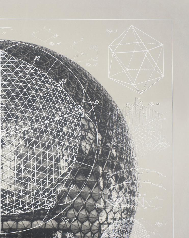
The Geodesic Dome, Buckminster Fuller11.

29
P r e c e d e n t P r o j e c t :
P e o p l e ’ s M e e t i n g D o m e
Commissioned by BL, Denmark Public
Housing for this year’s People’s
Meeting, an event conducted to
generate discourse surrounding
the future of housing, this project
regenerates the geometrical
nature of the geodesic dome by
implementing parametric modeling.
While respecting the properties of
the sacred dome and its invaluable
contribution to architecture across
history, the architects attempt to
deconstruct the shape in order to
allow the form to be manipulated
by the existing site conditions34.
Above: Deconstructing the geodesic dome, People’s Meeting Dome12.
The advantages in regards to the use
of parametrics is evident in this project
due to the increasing complexity
that is achieved when “unlocking”
a mathematically fused form. The
complex lattice like structural system is
designed in a unique way such that the
overall skeleton can be varied. It can
be configured according to a specific
set of parameters, disassembled
and constructed in a new layout,
with new parameters35. This poses a
distinct prospect for design innovation
where the boundaries of a defined
shape can be manipulated and
adjusted to optimize the design to be
efficient in utilizing the site’s features.
The technique of developing
form and space from base
geodesic geometry, involves the
implementation of parametric
modeling to engage with complex
mathematical operations. This
presents an ability to produce an
adaptable architectural solution
that responds to the site features
is a key facet of achieving
innovation. This will essentially,
become a key focus of my design
intentions, during the course of
exploring a suitable proposal for
the Western Gateway Project.

People’s Meeting Dome, Kristoffer Tejlgaard & Benny Jepsen, 201213

P r e c e d e n t P r o j e c t :
T h e A l m o n d P a v i l i o n S G 2 0 1 2 G r i d s h e l l
The following couple of projects pertain to a
particular technique similar to that of some
of the previous precedents discussed: The
use of a gridshell arrangement to generate
the structural characteristic of the design.
Both pavilions, focus on the utilization of parametric
tools to integrate the active-bending performance
of lightweight timber in a geodesic lattice form
to produce a highly efficient structure with
minimal material waste. The Almond Pavilion
was designed and constructed to effectively
explain the advantages of parametric modeling
in achieving a sustainable outcome, given the
relatively low budget of 1500 euros for the project36.
The Gridshell, a product of the SG2012 workshop,
focused on similar intentions of achieving material
efficiency through the use of parametric modeling.
31
The experiments were conducted by integrating
material and geometric parameters utilizing proficient
modeling software programs such as Grasshopper37,
which will be utilised in my own explorations with
parametric modelling in the forthcoming weeks.
Integration of generative, parametric modeling
tools to analyse physical properties of materials
such as timber is important in achieving efficiency in
terms of minimising waste as dictated by these two
precedent projects. The technique of assembling
elements to form a geodesic gridshell produces a
result that appears to complement the material
properties of timber creating a sense of openness
within the space that immediately connects with the
surrounding context, therefore will be explored in
further detail during the development of my design
proposal for the Western Gateway Design Project.
Below: Parametrics implementing geodesic curves to form a gridshell, The Almond Pavilion14, SG2012 Gridshell15

The Almond Pavilion,CODA, 201217
SG2012 Gridshell,Gridshell Digital Tectonics, 201216

The site for the Western Gateway Design Project,City of Wyndham18


A.4
Co n c l u s i o n
The primary focus of my design intentions are to produce a piece of architecture which
represent certain qualities which are unique to Wyndham. My proposal will aim to
engage both the surrounding context of the site as well as the cultural atmosphere in
order to present architecture as a source of inspiration through identification with the
society. The outcome will integrate the material properties of timber, one of the oldest
construction materials, the use of which has evolved along with the advancement of
technology in architecture. Extending the potential of materiality in architectural design,
further enhances my case for the future of Wyndham in regards to designing a suitable
proposal that defines architecture as that which evolves along with the rest of the world.
The process of design will push the boundaries of innovation through the use of
computational design techniques to generate form and space while implementing
advanced fabrication technologies for the purpose of prototyping possible design
solutions. As discussed previously, an important facet of the computational design
methodology will involve the use of parametric modeling to drive the developmental stage
of my design process. This results in increased productivity through design optimisation.
As I discovered, in my analyses of precedent projects, the technique of implementing
lattice geometry complements the properties of timber. This results in relatively light-
weight structures in which the user is subject to the open spatial qualities that can
be observed in the surrounding site context. I aim to achieve a design solution that
may potentially evoke a sense of reflection, thereby allowing a certain connection
to form between the audience, the architecture and the surrounding context.
A.5
Le a r n i n g Ou t c o m e s
As expected, the first few weeks of the subject initiated, what I believe to be, a crucial learning
curve in my study of architectural design. In this relatively short time span, I was immediately
forced to broaden my critical thinking in regards to architecture. I was surprised to have not
come across the term ‘discourse’ in previous studio environments, therefore it was a definite
matter of urgency that influenced me to enlighten myself into the field of architectural
literature. As someone who would have, not long ago, presented architecture as a mere
physical representation of an idea, I find my perspectives on the built environment to have
undergone a complete transformation in 3 weeks. Addressing a piece of architecture
beyond its mere aesthetical qualities became important to me during my research.
The technical component in regards to the weekly challenges enlarged my curiosity
in learning about the usefulness of parametric modeling tools such as grasshopper
and the ease by which one can obtain numerous trials in a matter of minutes by
adjusting parameters producing instant feedback. I found myself spending hours on
the program in an attempt to progress beyond what was required of me thereby
enhancing my knowledge of Grasshopper components and their respective functions.
Though, the nature of this project, right from the very beginning, involves being thrown
into the deep end, I found it very refreshing to be able to learn new skills as I was being
introduced to scripting as a valuable tool for parametric modeling. In retrospect, I feel that
these skills would have proved quite useful during the course of Virtual Environments as I
would have been able to produce results of higher complexity in a shorter time period.

A.6
Ap p e n d i x : Al g o r i t h m i c Ex p l o r a t i o n s
As part of my research into parametric modeling,
I was quite curious about how I might go about
replicating some of the characteristics of such projects.
The weekly algorithmic exercises enhanced my understanding
of scripting using grasshopper and were essential in
order to proceed forward with my design intentions.
The process of learning such complex software programs
revealed the importance of computation as a key
to broadening the prospects of architectural design.
One such attempt involved modeling the geodesic form,
similar to that of SG2012 Gridshell project. I was able to
efficiently generate geometry using Grasshopper with
help from the video tutorials. While it was a slow process to
start with, the results overall, were satisfying and proved
to be a very productive learning exercise as it would form
the basis of my design process in the coming few weeks.
Above: Grasshopper definition of the geodesic gridshell lattice, Algorithmic Exercises

38
Below: Explorations using Grasshopper to generate the geodesic gridshell form, Algorithmic Exercises
Part B - Expression of Interest II :An Approach to Design
39

Our objective is not to know the answers before we do the work. It’s
to know them after we do it.“ “
- Bruce Mau
40
B.1.1
De s i g n Fo c u s
T h e W e r r i b e e R i v e r
Whether you have lived in Wyndham for five days or 50 years, everybody has an experience or a
memory of the Werribee River38.
“ “
- Peter Maynard, Iramoo Ward Councillor

Following the research conducted on precedent works to examine the architectural
techniques utilised to demonstrate the sense of identity and belonging, we decided
to explore the cultural significance of Wyndham City. Over the years, the city has
experienced a high influx of population and is expected to grow quite significantly over
the next few years. There are multiple reasons that could be assumed to have caused
this attraction away from the city. One in particular that was observed, is Wyndham’s
connection with the Werribee River, a significant body of water that has been of
great significance for generations dating back to its traditional owners. The river is
considered to be a place of solitude and holds a certain sense of reverence amongst
the residents38. The natural feature has presided over expansive development of
Indeginous communities in the past such as the Watharung, Wundjeri and Boonerwrung
tribes in the same way as it overlooks the growth of Wyndham’s municipality today.
In pursuing a suitable solution that represents Wyndham, our team aims to focus
on celebrating the iconic significance of the Werribee River by presenting its
experiential qualities that hold a strong sense of identity, both with the people of
Wyndham as well as its traditional owners. The final outcome must create a sense
of stillness, a contrast from the surrounding fast paced scene of the highway.
42
W a t h a u r o n g
W u r u n d j e r i
B o o n e r w r u n g
Werri bee
River
C h a f f e y
I r a m o o
H a r r i s o n
Werri b
ee Ri ver
T H E K U L I N N A T I O N W Y N D H A M C I T Y W A R D S
Above: Maps revealing the community development around the banks of the Werribee River.


The Werribee River19.

P A T T E R N D E V E L O P M E N T
F O R M F I N D I N G
Case Study
2.0
Division of
Wyndham
City
Technique
development
Form
Development
Desired
System
Reverse EngineerIntegrate
Form SketchingRefine
B.1.2

46
After the initial algorithmic experiments conducted during our explorations in Part A, we
proceeded to develop a design technique. The process will be split in two facets which
will occur simultaneously: Pattern Development and Form Finding. This is done in order to
implement a combination of design concepts to achieve the intended final outcome.
Though my initial research into pattern development led into using techniques such
as implementing geodesic curves, as a team, we had arrived at a conclusion that
while there are benefits to such methods of generating geometry, it was difficult
to achieve further development beyond what has already been done before. The
resulting dilemma forced us to rethink and revise our design intentions with what it is
we want to achieve in this project, before exploring a new technique or combination
of techniques. The primary focus was to produce architecture that recreates a
similar experience that is encourages the audience to reflect, creating a sense of
identification with Wyndham, a similar function present in the serene environment
presented by the Werribee River. We envisioned that the use of sunlight available
in the vast, open space on site, could be utilised to achieve such qualities. The
design must consist of openings, varied in size, thereby manipulating the light
forming patterns on the ground. This had led us to implement a combination of
techniques such lattices as well as tessllation. In our case study explorations, we
aim to focus our experiments on deriving a technique that is unique to our design
proposal. Prototyping suitable outcomes will lead to refinement phase of this process.
To explore form finding which initially occurs independent of the pattern generation
phase, we aim to focus upon the importance of further emphasising our over
arching focus in representing Wyndham City. The form development will also
be extensively explored using grasshopper to generate a variety of outcomes
as we aim to achieve a suitable solution which can then be integrated with the
generated pattern as we move towards the final stages of the design process.
Design
Proposal

Gridshell Pavilion for Naples School of Architecture Courtyard20.


Ca s e St u d y 1 . 0
B.2

In the absence of a supplied definition for the ‘grids and lattices’ material system,
we chose to create our own script using the knowledge gained in the previous
weeks. The main purpose of this case study is to experiment with Grasshopper
to generate a large variety of outcomes that could be analysed to form the
basis by which we may be able to make suitable design decisions in the future.
The algorithm includes components which generate a base surface which can be distorted
using attractor points. Using the Lunchbox plugin, a suitable hexagon grid was chosen and
applied with ease on the surface. The polylines obtained were then extruded to obtain a
level of thickness. The definition consisted of various parameters that could be adjusted to
influence both the form and the arrangement of the pattern of hexagons on the surface.
This process enables us to gain more depth in our understanding of scripting
techniques which will be highly valuable through the course of our design
approach to create a suitable outcome for the Gateway Design Project.
50

The following pages contain the results of our algorithmic experiments using
Grasshopper and LunchBox. The matrix to the right shows an overview of the variety of
parameters that were manipulated to influence the nature of the resulting geometry.
Changes were applied to parameters one at a time and the outcomes were ‘baked’
and recorded. The parameters which were manipulated were the following:
Divisions of hexagonal cells in the grid (A)
Changes to the graph which influence the distortion of the surface (B)
Manipulation of the Attractor points influencing the overall vector field (C)
Adjustments to the charge and rate of decay values (D)
Culling pattern implemented to vary the arrangement of hexagonal cells (E)
Outcomes 1A - E were deemed unsatisfactory due the lack of definition in the
form which was a result of the low UV cell division on the surface. Outcomes
from the D row described an extreme variation of form and was thereby useful
in understanding the effects of adjusting the values of the charge and decay
rates. The culling pattern implemented to vary the arrangement of hexagonal
cells (row E) produced interesting outcomes and gave an understanding of
potential patterning ideas for our future explorations with elements of lattices.
Through this rigorous experimental process of obtaining numerous alternatives using
the same algorithm, we obtained a variety of potential solutions. However, we weren’t
completely convinced and felt it was necessary to explore further into geodesic
geometry in the next case study. The implemetation of Kangaroo Physics was also
deemed necessary in embedding material properties of timber to generate our form.
* We decided that this particular pattern of hexagonal cells was a desirable
outcome in our detailed explorations as we felt that it consisted of suitable
density of cells without being overly cluttered while providing sufficient definition
to our geometry.
51

52
1 2 3 4 5
A
B
C
D
E
*
M A T R I X 1
No. of UV Divisions 63 12 30 50

53
1
A
B
C
D
E
F
*Culling Pattern
FalseTrue
FalseTrueTrue
FalseFalse True
TrueTrueFalse
True TrueFalse True
TrueTrueFalseFalse

54
2
M A T R I X 2
Matrix 2 focuses on the pattern of the hexagonal cells
on the surface. The use of a component that is able to
effectively ‘cull’ certain elements of a list of data enables a
variety of outcomes to be obtained. While column 1 consists
of the original hexagonal pattern, column 2 implements an
alternative hexagonal layout which is diagonal. Culling series
of cells in a pattern produced larger openings on the surface.
This had the potential to be used to manipulate the entry of
light within the space to futher enhance the experiential
qualities of the gateway. It was interesting to note that the
culling occured differently in the outcomes in column 2
due to the variation in the order of data in the geometry.
Therefore it was not possible to produce a hexagonal
arrangement rather than a sequence of branching curves.
*Therefore, the outcomes from column 1 were preferred to
be more successful.

55
A
B
C
D
E
F
1
*

56
2
M A T R I X 3
Charge = 0.70Rate of Decay = 0.36
Charge = 0.40Rate of Decay = 0.36
Charge = 0.40Rate of Decay = 0.50
Charge = 0.12Rate of Decay = 0.05
Charge = 0.80Rate of Decay = 0.60
Charge = 0.12Rate of Decay = 0.70
Matrix 3 focuses on the form of the surface as we attempt
to obtain results that depict a variety of possibilities that
might be useful in future explorations. Column 1 presents
results of manually adjusting the attractor point locations,
thus manipulating the field of attraction which distorts
the geometry. Column 2 is a series of results produced by
further manipulation of point charge and its rate of decay,
potentially enhancing or in some cases degrades the field
allowing for a distinct collection of iterations. Outcome 2 D
was observed to be the most extreme condition, which was
interesting as we considered its potential in our design process.
*However, Outcome 1 B was prefered as it consisted of
a different variations which were not too extreme. The
potential of this outcome could be implemented on a roof
like structure similar to that of the Smithsonian Institution.

Tesellated Assemblies, Chrysallis (III), Matsys Design21.


B.3.1
Ca s e St u d y 2 . 0
H e x i g l o o P a v i l i o n

60
A product of a seven day workshop in Bucharest, the
Hexigloo Pavilion, was designed using parametric tools. A
hexagonal grid lattice forms the basis of the design. These
cells are mapped out on a pre-modeled surface and
extruded to create a series of funnels that filter light into the
interior space. This produces a sense of contrast between
the exterior features and the complex interior instigating a
moment of surprise. The fabrication process was conducted
using laser cutters and assembled out of 6mm cardboard.
This is an interesting work of architecture that employs the
use of patterning tessellated elements based on a defined
hexagonal grid layout, enabling the manipulation of light
in the interior space. The resulting pattern of light within the
space produces an evocative experience for the audience.
Below, Right: The Hexigloo Pavilion22.

R E V E R S E E N G I N E E R I N G
B.3.2

62
The process of reverse engineering the Hexigloo pavilion was relatively straight forward.
During this exercise, we primarily focused on obtaining the pattern as opposed to
mimicking the entire form. The algorithm consisted of hexagonal cells which were
generated using the LunchBox plugin once more. These cells were then offset to create
smaller hexagonal geometry which formed the openings on the surface. The curves were
then extruded in the Z axis to generate the funnels. The degree of offset and extrusion
were determined as a result of a series of values generated using attractor points.
Compared to our explorations in Case Study 1.0, we decided to focus on
fewer variables this time round as we were more interested in achieving a
suitable variety of offsets and funnel lengths. The result of which could be
further developed in later stages to form a technique unique to our design.
The attempt at regenerating the pattern utilised in the hexigloo
pavilion was very useful in enhancing the team’s understanding
of parametric tools as we progress further in our design process.
63
A
B
C
D
1
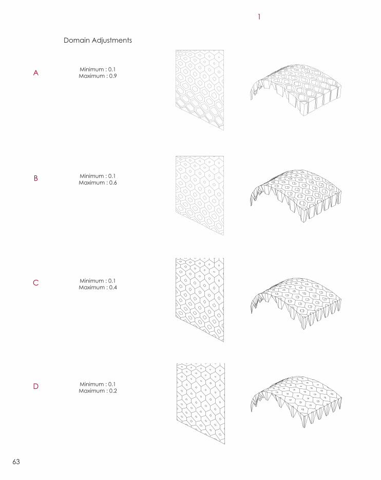
Domain Adjustments
Minimum : 0.1 Maximum : 0.9
Minimum : 0.1 Maximum : 0.6
Minimum : 0.1 Maximum : 0.4
Minimum : 0.1 Maximum : 0.2

64
Matrix 1 consists of the results of manipulating the values
set in the domain which restrict the size of the openings.
Two different hexagonal arrangements were tested.
Column 1 shows the results of a linear arrangement
where there is a gradual increase in the diameter of the
cell openings. Column 2 presents a radial spread where
the centermost cell consists of the smallest opening. This
was achieved by manually adjusting the position of the
attractor point on or away from the center of the surface.
We decided to proceed with neither of the sets of outcomes
as we desired to obtain a rigid and static variation of
funnel openings as opposed a gradual increase and
decrease. This will be explored as we progress further in
our technique developmental stage. Our intentions are
to achieve a sense of stillness in the pattern of light which
focuses the audience attention away from the contrasting,
fast-paced highway scene that forms the basis of the site.
M A T R I X 1
2

65
A
B
C
D
E
Domain Adjustments
Minimum : -0.5 Maximum : -0.1
Minimum : -1.0 Maximum : -0.5
Minimum : -5.0 Maximum : -1.0
Minimum : -10.0 Maximum : -1.0
Minimum : -15.0 Maximum : -1.0

66
Matrix 2 on the left focuses on the level of funneling that is
achievable, once again by manipulating certain values of a
set domain. This directly affects both the pattern of light that
penetrates the interior of the design as well as its intensity.
Outcomes A and B were suitable for further explorations
as we progressed into developing our own unique
parametric design technique. Outcomes D and E
appeared to be rather impractical and unrealistic
as the funnel lengths were too large that it would
hinder the interior spatial qualities that we desired.
The next step was to further test the rationality of some
of these outcomes by producing physical prototypes.
The results of this phase would better inform us on how
we may further develop and refine this technique
which will form the basis of our design proposal.
M A T R I X 2

Technique Prototyping, Case Study 2.0.


B.3.3
P R O T O T Y P I N G

70
After producing an algorithm that accurately generates
the funneling geometry of the hexigloo pavilion design,
We proceeded to test the funneling pattern by fabricating
a physical prototype. For the purpose of this experiment,
we decided to use black card as the primary material.
Overall the prototype was a success in enabling us to
view the resulting pattern of light that forms through the
funnels and we were quite satisfied with the outcome.
Above: Funnels, Case Study 2.0.
Below: Testing Light Pattern formations, Case Study 2.0.


Moving forwards, we decided that we
would like to focus on a more controlled
pattern that did not consist of a variety
of funnel openings but a strict contrast
between small and large openings. As
stated previously, this would allow a
certain degree of staticity providing the
desired sense of stillness within the space.
72Technique Prototyping, Case Study 2.0.

B.4.1
Te c h n i q u e : De v e l o p m e n t

In pursuing innovative patterning techniques, we
decided to explore our own pattern that we may
implement to the funneling definition produced in our
previous algorithmic experiments. Utilising the paneling
tools components within grasshopper, We were able to
generate a variety of patterns with ease from which we
could once again select one from a series of iterations.
*This particular tessellated pattern was chosen for
its symmetrical nature of elements. We decided
that the octagonal shapes would be regions which
are ‘funneled’, while the pentagons would be flat
panels forming part of the structural component
of the design as observed from the exterior.
*
74

75
The next step was to further develop the pattern to
extract the octagonal shapes to generate the funneling
geometry. The pattern had to be culled in a specific way
in order to obtain the alternating sizes of funnel openings
in the “big, small, big, small” arrangement that we desired.
The team reached a point in our development process
where we noticed that the pentagonal panel geometry
were not planar. This is one of the few flaws of patterning
complex geometry using grasshopper as one must always
test if the resulting panels are flat or doubly curved as this
may lead to extensive complications in the unrolling and
fabrication process. To resolve this, we had to triangulate
the geometry towards the center to obtain planar surfaces
while maintaining the curvature of the surface. This meant
that each triangle was to be its own panel and must be
connected seperately. This increased the complexity of our
patterning solution which we found to be a desirable outcome.
Above: Triangulation of surfaces

76
Above: paneling the geometry onto a curved surface
Below: Alternating sizes of funnel openings.

Te c h n i q u e : Fo r m Fi n d i n g
B.4.2

The initial stages of the form finding process
involved basic explorations using Rhino and
Grasshopper to brainstorm potenital solutions.
We were unsatisfied with majority of the outcomes where the
design was open at multiple areas. This would directly impact
how people move across the space. To ensure that visitors
experience the depth in the reflective experience that we
intended, we had to ensure that they remain within the space
as opposed to walking across from one end to the other.
The benefits of integrating parametric tools was that
we were able to quickly produce a set of iterations by
manipulating control points of loft curves in rhino, while
still obtaining direct feedback through the grasshopper
algorithm. In combining both pattern and form, we
anticipate that this will be very helpful, particularly
in the refinement stages of the design when we can
adjust small details such length of span and height.
78

The development of the form for the gateway design
focused on the circulation pattern of visitors within the
structure. We do not intend for the users to pass through
a large span of the structure, rather move in and settle
down into the space, experiencing the stillness we hope
to initiate with the light patterns projected on the ground .
As we refined this further, we considered the idea of
having multiple structures to accomodate a larger
number of visitors into the site. This seemed a better option
when compared to increasing the span of the structure,
which could potentially lead to a congested space
within the enclosure. Going back to the compositional
arrangement of Wyndham City, we observed a similar
composition when compared to the development of
the Kulin nation surrounding the Werribee River. This
fact was able to be directly translated into our design
as we decided to produce 3 pavilions of different
scales aligned in a radial arrangement, mimicking the
divisions of the community of Wyndham City.
As we refined this further, we considered the idea of
having multiple structures to accomodate a larger
number of visitors into the site. This seemed a better option
when compared to increasing the span of the structure,
which could potentially lead to a congested space
within the enclosure. Going back to the compositional
arrangement of Wyndham City, we observed a similar
composition when compared to the development of
the Kulin nation surrounding the Werribee River. This
fact was able to be directly translated into our design
as we decided to produce 3 pavilions of different
scales aligned in a radial arrangement, mimicking the
socio-political divisions of Wyndham City.
T h e K u l i n N a t i o n
W y n d h a m C i t y W a r d s
Te c h n i q u e : Fo r m Fi n d i n g

Overall, the generation of ideas for the form
and arrangement of the gateway design
relied upon a comination of elements
resulting in what we perceive to be a well
considered form, which will be ideal for
attracting both locals and visitors alike.
T h e K u l i n N a t i o n
W y n d h a m C i t y W a r d s
Above: Form Finding

B.4.3
Te c h n i q u e : F i n a l Ou t c o m e

80
To the right is the result of integrating both our
developed pattern and our ideas for form for
our design. In our final refinements, we decided
to restrict the amount of funneled openings to
just the top region. This is to further isolate the
audience to the boundaries of the structure by
concealing the views of the highway, thereby
focusing the attention within the space.
Right: Combining pattern with form.


82
To obtain a more informed understanding in regards to the
buildability of our design, we chose to explore potential joint
details that could be implemented to connect adjacent
panels together. Since our teams explorations in our design
development phase consisted of implementing planar
surfaces, we decided that sheet materials would be an ideal
pathway to take. In our research, we did observe that steel
would be a better course of option in terms of achieving
structural integrity and durability. However, this would
intefere with the notion of contrast between a natural setting
within an urban condition, that we intend on recreating
with our gateway design. Therefore, we returned back to
implementing timber to maintain the experiential qualities
in regards to the natural conditions of the Werribee River.
Tectonic Prototyping
Te c h n i q u e : Te c t o n i c
Pr o t o t y p i n g
B.5

Our first connection prototype consisted of the
implementation of H-clips to join adjacent panels of the
funnel. The results of this test proved to be unsucessful in
achieving what we had originally intended for it. The
joints created gaps between each panel which would
undoubtedly diffuse the light penetrating through, greatly
impacting the effectiveness of the pattern projected on the
ground. We did however gain a valuable understanding in
regards the structural feasability of these joints as they were
able to hold the overall shape together without the need for
additional reinforcement. In an architectural scale however,
these connections may not possess the same integrity. In
moving forwards, we decided to pursue further research
into how we may efficiently produce joinery elements
that could also be considered at an architectural scale.
84
Above: Series of Images showing the H-clip connection system.

85
Above: Prototype of steel bracket connection system.

86
In our research into joining systems pertaining to timber
surfaces, we explored a more generic approach of
implementing steel brackets to connect adjacent
panels together. For the purposes of testing at the scale
of a model, we used card as opposed to plywood. The
brackets were aligned and attached using a pin and
key connection. In the actual scale, these brackets
would ideally be bolted into the plywood panels.
While the system worked quite efficiently, We felt
that we werent pushing for an innovative method
of generating connections parametrically, rather,
implementing standard construction methods
which are common in most architectural projects
which deal primarily with joining timber elements.
In progressing forwards, we chose to consider steel as
a potential material that could form an underlaying
lattice structure upon which we can attach the panels
and funneling components. However more testing was
required to better inform our design intentions for the
connection details.
Above: Construction detail of steel bracket connection system.

Te c h n i q u e Pr o p o s a l
B.6
Above: Perspective View of the proposed gateway design.
88
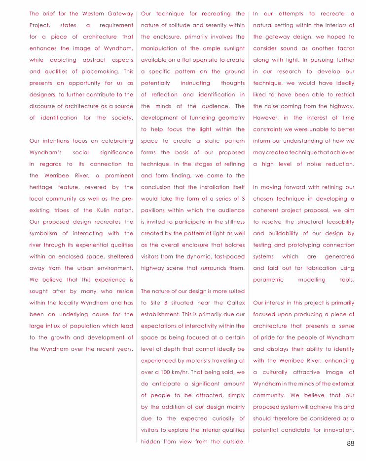
The brief for the Western Gateway
Project, states a requirement
for a piece of architecture that
enhances the image of Wyndham,
while depicting abstract aspects
and qualities of placemaking. This
presents an opportunity for us as
designers, to further contribute to the
discourse of architecture as a source
of identification for the society.
Our intentions focus on celebrating
Wyndham’s social significance
in regards to its connection to
the Werribee River, a prominent
heritage feature, revered by the
local community as well as the pre-
existing tribes of the Kulin nation.
Our proposed design recreates the
symbolism of interacting with the
river through its experiential qualities
within an enclosed space, sheltered
away from the urban environment.
We believe that this experience is
sought after by many who reside
within the locality Wyndham and has
been an underlying cause for the
large influx of population which lead
to the growth and development of
the Wyndham over the recent years.
Our technique for recreating the
nature of solitude and serenity within
the enclosure, primarily involves the
manipulation of the ample sunlight
available on a flat open site to create
a specific pattern on the ground
potentially insinuating thoughts
of reflection and identification in
the minds of the audience. The
development of funneling geometry
to help focus the light within the
space to create a static pattern
forms the basis of our proposed
technique. In the stages of refining
and form finding, we came to the
conclusion that the installation itself
would take the form of a series of 3
pavilions within which the audience
is invited to participate in the stillness
created by the pattern of light as well
as the overall enclosure that isolates
visitors from the dynamic, fast-paced
highway scene that surrounds them.
The nature of our design is more suited
to Site B situated near the Caltex
establishment. This is primarily due our
expectations of interactivity within the
space as being focused at a certain
level of depth that cannot ideally be
experienced by motorists travelling at
over a 100 km/hr. That being said, we
do anticipate a significant amount
of people to be attracted, simply
by the addition of our design mainly
due to the expected curiosity of
visitors to explore the interior qualities
hidden from view from the outside.
In our attempts to recreate a
natural setting within the interiors of
the gateway design, we hoped to
consider sound as another factor
along with light. In pursuing further
in our research to develop our
technique, we would have ideally
liked to have been able to restrict
the noise coming from the highway.
However, in the interest of time
constraints we were unable to better
inform our understanding of how we
may create a technique that achieves
a high level of noise reduction.
In moving forward with refining our
chosen technique in developing a
coherent project proposal, we aim
to resolve the structural feasability
and buildability of our design by
testing and prototyping connection
systems which are generated
and laid out for fabrication using
parametric modelling tools.
Our interest in this project is primarily
focused upon producing a piece of
architecture that presents a sense
of pride for the people of Wyndham
and displays their ability to identify
with the Werribee River, enhancing
a culturally attractive image of
Wyndham in the minds of the external
community. We believe that our
proposed system will achieve this and
should therefore be considered as a
potential candidate for innovation.

B.7
Le a r n i n g Ou t c o m e s
92
As with the initial few weeks of the subject, I was confronted with challenges arising from
different facets of the process of design, be it presenting a strong, convincing arguement,
or the consideration of different scales through which I must focus my design refinements
on, both in terms of construction details as well as the overall structural integrity of the
design. Prototyping and testing our Case study explorations proved to be a strong driver of
our progress through the course of the last few weeks. The importance of physical tests was
stressed by our tutor in the studio sessions. Gaining valuable feedback from the tutor was of
high priority to me as I made it a point to deliver my progress each week. This gave myself
and my fellow team-mates a sense of direction and a goal that we can work towards each
week. In leading up to the mid semester presentation, there was a strong emphasis on
establishing an overarching idea that forms a coherent arguement for our design proposal.
In terms of software, my skills have significantly developed since the start of the semester,
particularly with the use of grasshopper to generate complex forms by manipulating data
structures. I noticed an improvement in the speed and efficiency at which I was able to analyse
data trees and come up with list manipulation techniques to achieve the intended outcome.
The feedback from the presentation panel, was relatively mixed as we recieved both
positive comments along with certain flaws that were exposed to our attention. Our
concept overall was received quite well, however our lack of clarity in presentation was
critiqued heavily. Moving on from this point, our team has a strong goal that we want to
achieve with our design within the remaining few weeks. One of the major focus will be to
resolve the key elements of our design and test its feasability by producing more prototypes.
We also hope to improve the clarity of our presentation skills in remaining consistent
to the allotted time limit while clearly informing the audience of our design intentions.

B.8
Ap p e n d i x - Te c h n i q u e Al g o r i t h m
A significant amount of time and effort was spent working on producing a
working definition of our chosen technique exploration. The major components
of grasshopper that are used in this algorithm pertain to manipulating lists
and organising them to extract certain pieces of data that was required
to be able to parametrically model the design intentions of my team.
The ‘list item’ component was the go-to method of analysing the composition
of a specific data structure. The use of the series component enabled me to
reorganise elements in the list that could be extracted seperately. The experience
of engaging with these tasks in regards to data matching and manipulating was
very useful in enhancing my knowledge of how computational coding performs
and broadened my perspectives on what could and couldn’t be achieved.
Certain repetitive pieces of code within the algorthm were ‘clustered’ to
improve computing efficiency by simplifying the congestion on the canvas.
This gave me an understanding of how the original grasshopper components
may have been ‘clustered’ from even smaller pieces of algorithmic functions.

94
Below: Grasshopper algorithm to generate the proposed technique.

95
Part C - Project Proposal :Establishing Wyndham’s Identity

96
Establishing Wyndham’s Identity

C.1
De s i g n Co n c e p t
Gateway Project

98
Following on from the feedback received from various design consultations, there
were several areas within our proposed technique that required further refinement.
One of the major concerns was to address the issue of triangulation and the resulting
clarity in our originally intended pattern upon the surface. Triangulating to maintain
curvature upon the patterned surface is a crucial step in rationalising geometry
in order for it to be feasible. A potential alternative was to re-develop the form
into planar sections, however, we felt that this would not accurately represent our
intentions. Our intentions with the form were to produce a sheltered enclosure that
could house the reflective experiential qualities that result from the funneled openings.
Therefore, we pursued another pathway whereby we may explore the potential of
utilising these triangulated panels to further enhance the experience within the space.
Another important area that we needed to focus upon was the construction and
assembly of the enclosure. There were suggestions raised during our consultations,
that the composition of timber panels would not be sufficient enough structurally
and would therefore require additional support for the design to be buildable. A
possible solution that may address this issue was to implement a framing system,
which consisted of members with a level of depth sufficient to add structural integrity
to the enclosure. The timber panels would then be ideally laid upon the frame.
Our refinement stage of the proposed technique needed to include a more focused
integration of materiality within the design. As a team we were encouraged to specify
a specific type of timber that may intensify the aesthetic qualities of the gateway
design while address the issues of longevity and maintenance requirements that
arise from using timber that is exposed to potentially strenuous weather conditions.
Lastly, the positioning of the gateway enclosure on site was also to be
considered. The orientation with respect to the changing level of sunlight
across the day was an important factor that would undoubtedly have an
impact on the amount of sunlight that may penetrate through into the space.
C o n c e p t R e v i e w

95C.1.2
Aerial view showing the position of the enclosure in Site B.

100
R e v i s e d C o n c e p tIn the process of establishing the proposed gateway enclosure
on site B, our main considerations primarily focused on the
convenience in accessibility. We had to ensure that the
entrance appropriately faced the Caltex Station from which
we expected visitors would stop and approach the structure.
Secondly, in consideration of the point of view of motorists on
the highway, we positioned the pavilion closer to the road
directing travelers towards Wyndham. We felt that this would
be highly appropriate as motorists would presumably be curious
as they approach the enclosure and are immediately given the
opportunity to turn into the Caltex Service Station, encouraging
them to stop and explore the interior of the gateway pavilion.
While the pavilion is relatively small in scale, spanning 20
metres across and 6 meters in height, the flat topography of
the site enables a significantly large depth of view from a far.
The position of the openings for the funnels were also shifted to
the side facing the north, to optimise the use of the sunlight that
penetrates the interiors of the enclosure space as much as possible.
Aerial view showing the position of the enclosure in Site B.
Above: The revised design proposal.

101 Above: Spotted Gum (Corymbia Maculata)23.

102
M a t e r i a l i t y
S P O T T E D G U M
In our considerations in regards to material selection, we focused
on achieving a certain level of durability and sustainability,
which are two key factors mentioned in the brief. In our
analyses of timber databases online, we came across several
potential timbers suitable for the gateway proposal. Ultimately,
we selected the Spotted Gum (Corymbia Maculata). The
approximate life cycle of the timber is 40 years, in conditions
above ground39, which in our assumptions, achieves a good
durability standard sufficient for the proposal. Being a native,
plantation hardwood, the Spotted Gum also satisfies a suitable
standard of sustainability in regards to its environmental impacts.
Another notable feature of the Spotted Gum is its gradual colour
change over its life time, when directly exposed to sunlight.
From an aesthetical point of view, we felt that the exterior of the
enclosure could exhibit these resulting changes symbolising the
slow deviations that occur that may be observed in a natural
setting. This presented another layer of depth in our ability
to recreate the experiential qualities of the Werribee River.
E S T I M A T E D C O L O U R C H A N G E O V E R T I M E
< 1 0 Y e a r s 3 0 + Y e a r s

Proposed Structural System..103

S t r u c t u r eAs stated previously, the surface of the enclosure required a
level depth to be able to be structurally feasible. After several
discussions amongst the members of the design team, we decided
to implement a steel framing system to function as the structural
element of the design. The initial sketch models as seen on the
left, describes our process of arriving at the proposed structural
solution. Utilising parametric tools, we were able to achieve the
desired size and depth of the steel members and also enabled us
to organise them into separate components ready for fabrication.
Though we had initially intended for the design of the
gateway to be composed of timber by itself, we felt that a
compromise had to be made in order to achieve an optimal
structural solution. The frame would consist of steel members
welded together with horizontal platforms upon which the
timber panels and funnel components could be attached to
(refer to C.2.2 for more information on specific joint details).
From the view of the exterior , we aimed for this steel frame to produce
a outline around the timber elements, emphasising the unique
patterning scheme designed for the proposed gateway enclosure.
Above: Sketch Models exploring structural elements.Below: Partial steel frame derived using Grasshopper.
104

Base Geometry
Pattern+
Form
Base Surface
OrganisingLists
Structural Frame
Flooring
105

Funnels
Pentagons+
Non-FunnelsTriangulation
Big Opening
Small Opening
Final Outcome
A L G O R I T H M I C W O R K F L O W
106

C.2.1
Gateway Project
Te c t o n i c El e m e n t s : Ke r f i n g
P r e c e d e n t P r o j e c t :
K e r f P a v i l i o n

108
While exploring innovative techniques of timber that could
be potentially implemented in the connection of the various
timber and steel elements, we stumbled upon this particular
technique of bending timber without the requirement
of steam or heat. Kerfing is a process of creating small
incisions in sheet timber creating specific points of weakness
allowing a certain degree of curvature to be obtained.
As observed in the images to the right, the Kerf pavilion the result
of combining the material logic of kerfing with the flexibility of
parametric modeling and modern day digital fabrication. The
pavilion structure is diverse in use from generating seating
and shading all at the same time of supporting the structure.
Our explorations with regards to prototyping this technique
involved a similar approach of utilising parametric algorithm
(Refer to Section C.5) to adjust the spacing and amount of
cuts to achieve a variety of different degrees of bending.Left and Below: Kerf Pavilion24.

Pr o t o t y p i n g In further research, we came across the potential of
implementing a variety of different patterns when
kerfing timber and obtain different outcomes. We
proceeded to generate prototypes to test the
varying degrees of deflection that we could achieve.
Firstly, our results indicated that the pattern of
lines cut against the grain of timber, performed as
intended as compared to the other patterns we
applied. We were able to bend the material to a
significant degree and we came to the conclusion
that the amount of cuts and their spacing directly
determined the performance of this technique. The
less the spacing, the greater the degree of deflection.
Above and Right: Kerfing technique prototyping.109

110
Our intentions were to apply this technique to
the components that composed the funnels.
Essentially, surfaces of the funnel were extended
in the vertical direction. Kerfing is applied at the
point of extension. This enables the component
to be bolted onto the steel frame, positioned
together with adjacent pieces, would form the
funnel. Initially, the fabricated components did
not function as intended and snapped. This was
mainly due to the spacing being too large. The
solution was to increase the amount of cuts
as well as reduce the spacing to obtain more
flexibility as observed in our previous explorations.
Making use of the aesthetical look of the kerf
pattern, we decided to use this technique
to design the furniture to be placed within
the interiors of the enclosure. The space
would feature timber flooring upon which
elements of seating would be fixed onto.
Above: Trial and error within the fabrication process of the funnel components.

C.2.2
Funnel Extension
Triangulated Panels
Steel Frame
Bolt Connection
Kerfing Incisions
Pin and Cam System
Above: Construction Detail Documentation. Scale 1:5

102
The fabrication and assembly of a 1:10 scale model was completed
in order to gain a better understanding of the feasibility of the
proposed steel structural system integrated with the timber panels
and funnels. Due to fabrication limitations, black card was used
in place of composite steel. 2.7mm thick luan plywood was
used to denote the timber elements. Rivets of 2mm in diameter
were used in place of bolts. Overall, the model was successful
in conveying our intentions and functioned as expected. An
important aspect that we overlooked during the fabrication
process was to allow for the tolerance factor. This affected the
process of assembly greatly as there was little room for error.
Below: Construction Detail Model. Scale 1:10.
112

Above: Triangulated Panels, Construction Detail Model. Scale 1:10.
113

As stated previously (Section C.1.1), we intended on utilising
the triangulated panels to further enhance the experience
within the enclosure. The gaps between individual panels
were left intentionally exposed to allow light to penetrate
through. This created small outlines of light that could be
viewed from the interiors, adding into the light which passes
through the funnels. The result overall could be denoted as
symbolising the fragments of light that penetrate through
the gaps of leaves of the trees situated along the river bank.
Below: Light Penetrating the gaps through triangulated panels, Construction Detail Model. Scale 1:10.
114

Cam
Pin
Funnel Component
Steel Frame
Above: Sectional Drawing of the Pin and Cam System
115

1
2
3
4 5
To indicate the connection detail of the components that
form the funnel, A 1:1 scale model was assembled, utilising
a Pin and Cam System.
1. The cam is essentially a hinge joint that can be adjust to
any angle as desired.
2. Holes are drilled on the side of the panels and the pins
are inserted.
3. The cam joint is inserted and positioned as desired.
4. The pins can to be rotated to pull and position the two
components together.
5. Two sets of joints are used on each of the intersections
of funnel components.
Left and Below: Process of Assembly, Pin and Cam System. Scale 1:1
116

Fabrication of Timber
Panels and Funnels
+Welding of Steel Frame into Small Sections
Transported onto site
117
M A N U F A C T U R E D O F F - S I T E

Assembly of Frame
Panels and Funnels installed
simultaneously+
Flooring and Furnishing+
W O R K F L O W O F T H E C O N S T R U C T I O N P R O C E S S
118

C.3.1

Gateway Project
Fi n a l Mo d e l :
As s e m b l y
120

We decided to produce two 1:20
scaled versions of our enclosure design:
1. An architectural model describing form, structure
and the effectiveness of the unique pattern as
viewed from the outside. The materials used
were 1mm Mountboard and 300GSM Black Card.
2. A section model, describing materiality,
interiors, as well as the experiential qualities.
Once again, we used 300GSM Black Card to
represent the steel frame, along with 1.5mm
premium laser plywood. The fabrication
process was conducted using the laser cutting
facilities available at the Melbourne University,
faculty of Architecture, Building and Planning
The layout of the triangulated elements of
the enclosure was initially unrolled as strips, to
enable accuracy without having to label each
individual panel. Each strip was then carefully
divided and the strips of the steel frame were
wrapped along the edges and glued in place.
The funnels were assembled in the assigned spacing
between adjacent strips of triangulated panels.
While it did seem unlikely at the start of the model
assembly process, we were able to observe
the curvature of the design taking shape as
we progressed. The intended patterns of light
produced by the funnels could were also observed.
The furniture to be placed within the enclosure,
composed of a large sheet of timber that could be
deflected to form the seating element. The pieces
of furniture were placed on the timber flooring
and the resulting outcome was quite successful
in describing our intentions for the interior layout.
This process was completed both for both models.
Both models were quite successful in its
completion and in regards to its accuracy
in describing the formal and structural
characteristics that was represented by the digital
model generated using parametric software.
121

Process of Assembly, Scaled Architectural Models. Scale 1:20.
122

C.3.2
The Final Models: A Successful Result.

124

Gateway Project
Fi n a l Mo d e l :
Re s u l t
125

The Final Models: Showing Formal Characteristics.
126

127

The Final Models: Mountboard and Black Card.
128
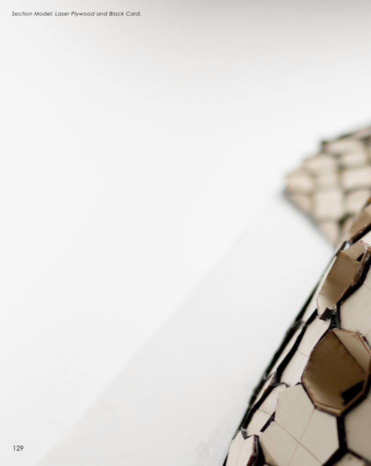
Section Model: Laser Plywood and Black Card.
129

130

Section Model: Flooring and Furniture Layout.
131

132

Pr o j e c t Co n c l u s i o n
Our proposed gateway design for this project,
outlines the characteristics that make the City of
Wyndham unique to the broader community. By
implementing architectural design to recreate
the experiential setting of the Werribee River
and depicting its significance, reinforce some
of the comments made in the previous sections
of this document, in regards to the aspect of
architecture being a successful medium to express
a sense of identification for the community.
The integration of computational design through
the use of parametric modelling techniques
and digital fabrication, along with exploration
of material performance, successfully
achieves the level of innovation set out by the
project brief and is evident throughout the
process of achieving the proposed design.
Finally, in contributing to the overall architectural
discourse, our enclosure design aims to add a
new perspective to the concept of a gateway,
through the creation of a reflective and
provocative experience at a personal level,
inviting motorists as they drive past, adding depth
to the overall engagement of the audience.
C.3.3
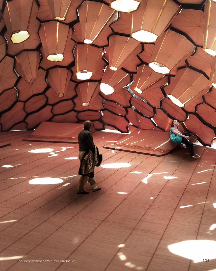
The experience within the enclosure. 134

Gateway Proposal: View from the motorist’s point of view.
135

136

Gateway Proposal: View from the Caltex Service Station.
137

138

C.4
Presentation Feedback:
Our final proposal for the gateway project was well
received by the panel of critiques. The proposed
pattern, designed to be unique to Wyndham
City’s gateway, was largely appreciated and
was deemed a success through our models.
The form was a primary area of concern as
there were questions raised in regards to
alternative solutions for the entrance that could
be potentially explored. In retrospect, the
considerable amount of time focused on resolving
the structural composition of the proposed
design, presented us with little or no time to
approach alternatives to formal characteristics.
From the positive comments we gathered that
we were effective in communicating our design
intentions was a welcome improvement from
that of the mid-semester presentation. The scaled
architectural models formed the prominent feature
as we aimed to deliver a convincing argument
and received positive remarks from the panel.

Le a r n i n g Ob j e c t i v e s a n d Ou t c o m e s
At the culmination of my efforts in Studio: Air, there has been an extensive
amount of knowledge that I have gained in a variety of different facets
of Architectural design. The ability to selectively apply knowledge
gained was tested throughout the design process. The results presented
in this document communicate my understandings of the process
of design in regards to design through computation and parametric
modelling, resolving complex problems in regards to achieving design
feasibility and addressing the issues of translating digital representations
to physical models through modern fabrication techniques.
In my progression through this semester, I have been largely successful in
achieving the outcomes set by the subject. In engaging with architecture
as a discourse, I have been able to identify the potential ideals that are
established through architecture, beyond that of a building’s aesthetical
qualities. I have gained a significant insight into parametric modelling
techniques and have been able to efficiently produce working design
algorithms that accurately represent my design intentions. In regards to
exploring an extensive range of possible design solutions, I feel that I
have only partially achieved the desired standards, mainly due to lack
of formal development in my design process. While the restricted time
constraints may have impacted the development of the design, I feel that
I could have potentially pushed the formal characteristics a little further,
particularly employing parametric tools to a greater effect. In gaining
important presentation skills, I feel confident in my ability to communicate
a convincing argument that is cohesive and relevant to the design brief.
Overall, the significant amount of experience and technical skills that I have
procured over the course of the semester would undoubtedly influence
my future endeavours in the field of architectural study and practice.
140

C.5
Ap p e n d i x - Al g o r i t h m i c Sk e t c h e s
Above: Construction Detail Algorithm.

Below: Kerfing Technique Algorithm.
142

143
1
2
3
4
5
6
7
8
9
10
11
12
13
14
15
16
17
18
19
20
I M A G E SPyramids of Giza. <http://loopele.com/wp-content/uploads/2013/07/Egypt-Pyramids-HD-Photo-Wallpaper1.jpg>
The Pantheon. <http://www.travelsrome.com/wp-content/uploads/2012/09/roman_pantheon.jpg>
The Cathedral of St. John. <http://connorboals.f i les.wordpress.com/2009/09/cathedral1.jpg>
The Taj Mahal. <http://media1.santabanta.com/full1/Architecture/TajMahal/tajmahal-28a.jpg>
Walt Disney Concert Hall. <http://pleasurephoto.fi les.wordpress.com/2012/10/disney-hall- los-angeles-frank-gehry-archi-
tect-jul ius-shulman-and-juergen-nogai-b.jpeg>
Burj Al Arab. <http://upload.wikimedia.org/wikipedia/en/archive/2/2a/20120813060112!Burj_Al_Arab,_Dubai,_by_Joi_
Ito_Dec2007.jpg>
The Bird’s Nest. <http://beij ingbirdsnest.f i les.wordpress.com/2010/09/birds_nest_stadium_beij ing_china-hd.jpg>
Museo Parc Alesia. <http://www.cotedor-tourisme.com/sites/default/fi les/recadree_MuseoParc_Alesia_Claire_Jachymi-
ak_SEM-Al%C3%A9sia.jpg>
<http://www.dezeen.com/2009/11/13/memorial-for-tree-of-knowledge-by-m3architecture/>
<http://www.prc-magazine.com/wp-content/uploads/2011/10/2010-04-3969-00-BarcaldineTreeofKnowledge-BrianHoop-
er.jpg>
<http://www.yatzer.com/Metropol-Parasol-The-World-s-Largest-Wooden-Structure-J-MAYER-H-Architects>
<http://upload.wikimedia.org/wikipedia/commons/4/46/Metropol_Parasol_Sevil la_2.JPG>
<http://projectsreview2011.aaschool.ac.uk/submission/uploaded_fi les/EMERGENT-TECHNOLOGIES/Core%20Studio%20
1-20101215_1400_DSC_0227.jpg>
<http://www.fosterandpartners.com/projects/smithsonian-institution/>
<http://www.fosterandpartners.com/projects/smithsonian-institution/>
<http://www.oliverdavid.de/wp-content/uploads/2011/11/1005_11.jpg>
<http://www.digitalcrafting.dk/wp-content/uploads/2011/11/HDRPanorama_julian-Lienhard.jpg>
<http://www.dexigner.com/news/image/22008/sfmoma_Fuller_Geodesic_Dome>
<http://www.sinbadesign.com/wp-content/uploads/2012/09/Peoples-Meeting-Dome-Drawing-top-view.jpg>
<http://api.ning.com/fi les/wr*6D7ZUFRrI39BCu5b80Z5nIO8Dbtl5S2duWkKhmZTqIp26ZcMtVPtEB3j8pm9sCBqXL7hubxVn-O6a
zx-nGk95NLwjwFE5/11.jpg>
<http://www.designboom.com/architecture/coda-barcelonatech-jukbuin-pavil ion/>
<http://matsysdesign.com/wp-content/uploads/2012/04/IMG_9422.jpg>
<http://matsysdesign.com/wp-content/uploads/2012/04/IMG_9469.jpg>
<http://www.designboom.com/architecture/coda-barcelonatech-jukbuin-pavil ion/>
Retrieved from the LMS.
<http://farm4.staticfl ickr.com/3127/2723775145_a897bab970_o.jpg>
<http://www.gridshell. it/blog/wp-content/uploads/2012/11/gridshell_napoli_010.jpg>

144
21
22
23
24
I M A G E S<http://matsysdesign.com/2012/04/13/chrysalis-i i i/>
<http://www.arch2o.com/hexigloo-pavil ion-tudor-cosmatu-ir ina-bogdan-andrei-raducanu/>
<http://www.topveneer.com.au/content/images/thumbs/0000141_spotted-gum-flat-cut.jpeg>
<http://futuresplus.net/2012/07/18/kerf-pavil ion-mit/>

N O T E S1
2
3
4
5
6
7
8
9
10
11
12
13
14
15
16
17
18
19
20
21
Jonathan Hil l , ‘Drawing Forth Immaterial Architecture’, Architectural Research Quarterly (2006), 10, 1, p. 51.
Patrik Schumacher, ‘Introduction : Architecture as Autopoietic System’, in The Autopoiesis of Architecture (Chichester:
J. Wiley, 2011), p. 1.
Richard Wil l iams, ‘Architecture and Visual Culture’, in Exploring Visual Culture : Definitions, Concepts, Contexts, ed. by
Matthew Rampley (Edinburgh: Edinburgh University Press, 2005), pp. 102.
Jonathan Hil l , ‘Drawing Forth Immaterial Architecture’, Architectural Research Quarterly (2006), 10, 1, p. 54.
Jonathan Hil l , ‘Drawing Forth Immaterial Architecture’, Architectural Research Quarterly (2006), 10, 1, p. 54.
Patrik Schumacher, ‘Introduction : Architecture as Autopoietic System’, in The Autopoiesis of Architecture (Chichester:
J. Wiley, 2011), p. 1.
Patrik Schumacher, ‘Introduction : Architecture as Autopoietic System’, in The Autopoiesis of Architecture (Chichester:
J. Wiley, 2011), p. 2.
Antoine L. Lahoud, ‘The role of cultural (architecture) factors in forging identity’, National Identities (Taylor and Francis
Group, 2008), 10, 4, p. 390.
Antoine L. Lahoud, ‘The role of cultural (architecture) factors in forging identity’, National Identities (Taylor and Francis
Group, 2008), 10, 4, p. 389.
Jennifer Tran, ‘Static I l lusions: Architectural Identity, Meaning and History’, (Curtin University), p. 2.
Jennifer Tran, ‘Static I l lusions: Architectural Identity, Meaning and History’, (Curtin University), p. 3.
Wyndham City Council, ‘Western Gateway Design Project v02’, Retrieved from the LMS, p. 4.
M3architecture, ‘Bacarldine Tree of Knowledge’, (2009), <http://www.m3architecture.com/> [Accessed on 8th August,
2013]
Dezeen Magazine, ‘Memorial for Tree of Knowledge by m3architecture and Brian Hooper’, (2009), <http://www.dezeen.
com/2009/11/13/memorial-for-tree-of-knowledge-by-m3architecture/> [Accessed on 8th August, 2013]
National Architecture Awards Jury 2010, ‘Heritage Architecture Awards 2010’, in Architecture Australia (Australia: Archi-
tecture media Pty Ltd., 2010), 99, 6,
Michael Webb, ‘Metropol Parasol by Jürgen Mayer H.’, in Architectural Review, (2011), <http://www.architectural-re-
view.com/metropol-parasol-by-jrgen-mayer-h-architekten-sevil le-spain/8615207.article> [Accessed on 9th August, 2013]
J. Mayer H., ‘Metropol Parasol’, (2011), <http://www.jmayerh.de/19-0-Metropol-Parasol.html> [Accessed on 9th August,
2013]
Kostas Terzidis, ‘Algorithmic Architecture’, (Oxford: Architectural Press, 2006), p XI.
Yehuda E. Kalay, Architecture’s New Media : Principles, Theories, and Methods of Computer-Aided Design (Cambridge,
Mass.: MIT Press, 2004), p. 4.
Kostas Terzidis, ‘Algorithmic Architecture’, (Oxford: Architectural Press, 2006), p XI.
Brady Peters, ‘Realising the Architectural Intent: Computation at Herzog & De Meuron’. in Architectural Design (Chichester:
John Wiley & Sons, 2013), 83, 2, pp. 59.
145

22
23
24
25
26
27
28
29
30
31
32
33
34
35
36
37
38
39
Sean Ahlquist and Achim Menges, ‘Introduction’, in Sean Ahlquist and Achim Menges (eds), Computational Design
Thinking, (Chichester: John Wiley & Sons, 2011), p. 2.
Mark Burry, Scripting Cultures, (Chichester: John Wiley & Sons, 2010), p. 8.
Branko Kolarevic and Ali Malkawi (eds), ‘Performative Architecture: Beyond Instrumentality’, (New York: Routledge,
2004).
Brady Peters, Smithsonian Institution, (2007), <http://www.bradypeters.com/smithsonian.html> [Accessed on 9th Au-
gust, 2013]
Brady Peters, ‘Computation Works - The building of Agorithmic Thought’, in Architectural Design (Chichester: John
Wiley & Sons, 2013), 83, 2, p. 13.
Foster and Partners, ‘Smithsonian Institution’, (2007), <http://www.fosterandpartners.com/projects/smithsonian-institu-
tion/> [Accessed on 9th August, 2013]
Achim Mengis, ‘Material Computation: Higher Integration in Morphogenetic Design’, in Architectural Design (Chich-
ester: John Wiley & Sons, 2012), 82, 2, p. 17.
Achim Mengis, M. Fleischmann, J. Knippers, J. Leinhard and Simon Schleicher, ‘Material Behaviour’, in Architectural
Design (Chichester: John Wiley & Sons, 2012), 82, 2, p. 45.
Eric Weisstein, ‘CRC Concise Encyclopedia of Mathematics’, (Florida: Chapman & Hall, 2003).
Daniel Davis, ‘Introduction to Parametric Modeling’, in Architecture Design Studio: Air, Lecture 3 (2013).
Rick Smith, ‘Technical Notes from Experiences and Studies in Using Parametric and BIM Architectural Software’,
(2007), <http://www.vbtllc.com/images/VBTTechnicalNotes.pdf> [Accessed on 15th August, 2013]
Parametric Technology Corporation, ‘Explicit Modell ing: What do you do when your 3D CAD productivity isn’t what
you expected’, (2008), <http://www.vbtllc.com/images/PTCProductivityWhitePaper.pdf> [Accessed on 15th August,
2013]
I.D. Magazine, ‘People’s Meeting Dome, a deconstructed geodesic dome’, (2012), <http://www.id-mag.com/gallery/
Peoples-Meeting-Dome/5228001> [Accessed on 10th August, 2013]
I.D. Magazine, ‘People’s Meeting Dome, a deconstructed geodesic dome’, (2012), <http://www.id-mag.com/gallery/
Peoples-Meeting-Dome/5228001> [Accessed on 10th August, 2013]
Design Boom, ‘CODA barcelonatech: jukbuin pavil ion’, (2012), <http://www.designboom.com/architecture/coda-
barcelonatech-jukbuin-pavil ion/> [Accessed on 15th August, 2013]
SG2012, ‘Gridshell Digital Tectonics’, (2012), <http://smartgeometry.org/index.php?option=com_content&view=articl
e&id=134%3Agridshell-digital-tectonics&catid=44&Itemid=131> [Accessed on 15th August, 2013]
Wyndham City Council, ‘Share Your Werribee River Stories’, (2013), <http://www.wyndham.vic.gov.au/aboutwynd-
ham/pubmedia/media/2013/july/werribee_river_stories> [Accessed on August 28th, 2013]
Wood Solutions, ‘Spotted Gum / Corymbia maculata’, <http://www.woodsolutions.com.au/Wood-Species/spotted-
gum> [Accessed on September 1st, 2013]
N O T E S
146

T H E U N I V E R S I T Y O F M E L B O U R N E