studies on a new high-intensity low-emission burner
TRANSCRIPT
1131
Proceedings of the Combustion Institute, Volume 29, 2002/pp. 1131–1137
STUDIES ON A NEW HIGH-INTENSITY LOW-EMISSION BURNER
SUDARSHAN KUMAR, P. J. PAUL and H. S. MUKUNDACombustion Gasification and Propulsion Laboratory
Department of Aerospace EngineeringIndian Institute of ScienceBangalore 560 012, India
This paper presents computational and experimental results on a new burner configuration with a mildcombustion concept with heat release rates up to 10 MW/m3. The burner configuration is shown to achievemild combustion by using air at ambient temperature at high recirculation rates (�250%–290%) bothexperimentally and computationally. The principal features of the configuration are: (1) a burner withforward exit for exhaust gases; (2) injection of gaseous fuel and air as multiple, alternate, peripheral high-speed jets at the bottom at ambient temperature, thus creating high enough recirculation rates of the hotcombustion products into fresh incoming reactants; and (3) use of a suitable geometric artifice—a frustumof a cone to help recirculation. The computational studies have been used to reveal the details of the flowand to optimize the combustor geometry based on recirculation rates. Measures, involving root meansquare temperature fluctuations, distribution of temperature and oxidizer concentration inside the pro-posed burner, and a classical turbulent diffusion jet flame, are used to distinguish between them quanti-tatively. The system, operated at heat release rates of 2 to 10 MW/m3 (compared to 0.02 to 0.32 MW/m3
in the earlier studies), shows a 10–15 dB reduction in noise in the mild combustion mode compared to asimple open-top burner and exhaust NOx emission below 10 ppm for a 3 kW burner with 10% excess air.The peak temperature is measured around 1750 K, approximately 300 K lower than the peak temperaturein a conventional burner.
Introduction
Development of a system with high efficiency andlow pollutant emissions for a better environment andbetter energy resource management is continuing tobe pursued by the combustion community. Manytechniques, such as flame cooling, staged combus-tion, reburning, and exhaust gas recirculation, areproposed to reduce NOx emissions [1]. The exhaustgas recirculation for NOx reduction is drawing in-terest because of its promising features [1–6]. In thismethod, combustion products are recirculated andmixed into the fresh incoming fuel and air streams.This reduces the concentration of the reactants,thereby reducing the reaction rates avoiding the for-mation of sharp zones of high temperatures in thecombustion chamber [1]. When recirculation ratesare below 30%, the flames are stable at all tempera-tures. There also exists another stable combustionmode when the recirculation rates are very high andtemperatures are higher than the autoignition tem-perature of the fuel. This stable mode of combustionis termed as flameless combustion or mild combus-tion [1–4]. The key approach to reduce NOx emis-sion in this method is by reducing the thermal NOxformation rate, directly dependent on the distribu-tion of temperature and its fluctuations in the com-bustion process [7,8].
Wunning and Wunning [1] established the flame-less combustion in highly recirculating combustionchamber and proposed low NOx and noise emissionburners for industrial applications through the useof high-inflow air temperatures. The high speed jetsof preheated air and methane (fuel) entrain largequantities of combustion products and attain the au-toignition temperature before the reaction starts be-tween fuel and oxidizer. Recuperation and/or regen-eration are used to preheat the incoming air to hightemperatures. In several of these studies [2,4,5], re-verse-flow geometry has been used to create theflameless combustion phenomenon; the aerother-mochemical features are mapped at high recircula-tion rates to quantify the operational characteristicsof the burner under different operating conditionsin premixed (lean and rich) and non-premixed re-gimes. Experiments indicated that flameless com-bustion falls in a stirred reactor regime where si-multaneous ignition and extinction phenomena areabsent [2]. Weber et al. [9] have shown in their workthat both air and fuel entrain considerable amountsof combustion products, and combustion proceedsat rates lower than in conventional burners. A recentstudy by Katsuki and Hasegawa [10] indicates theneed for highly preheated air for creating mild com-bustion, and this has been commented upon byWunning, indicating that it would work even without
1132 NEW CONCEPTS IN COMBUSTION TECHNOLOGY—Mild Combustion
TABLE 1Summary of the previous work on mild combustion
Ref. Geometry FuelHeat release rate
(kW/m3)TAir
(K)EINOx
(g/kg fuel)TOperating
(K)
[1] Multipoint injection burner Methane Not known 1073–1373 2.19 1573[2] Reverse-flow geometry Methane �320 773 0.27 1650[4,5] Reverse-flow geometry Methane �180 650 0.11 1650[10] Regenerative burner Natural gas 23 1573 1.23 Not known[12] High-heat intensity burner LPG 5000 300 0.35 1650[13] Blue-flame burner at (� � 0.91) Kerosene Not known 300 0.77 1750
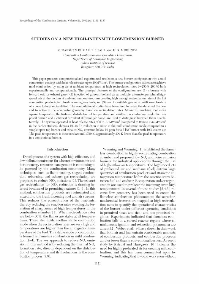
Fig. 1. The optimized burner configuration with its de-tailed dimensions. (a) Cylindrical configuration with centralfuel and surrounding air; (b) modified configuration withalternate peripheral injection jets and secondary air.
preheating. The authors [10], in response, hint fur-ther that this feature will be true in large systemsnot affected by heat losses leaving a residual positionof non-clarity on the issue as to what happens forsmall power systems. The present work will answerthe question in favor of Wunning’s assertion by dem-onstrating mild combustion at low power level withhigh heat release rates using fuel and air at ambienttemperature.
The heat release rates in the previous experiments[2,4,5,7,11] are very small, varying from 23 to �320kW/m3 as shown in Table 1. It is the aim of thecombustion system design to achieve high heat re-lease rates while meeting the requirement of lowemissions. The objective of current research is todevelop a new burner with following features:(1) low chemical emissions and noise, (2) high heat
release rates (2–10 MW/m3), (3) wide operatingrange for different fuels, and (4) achieving mild com-bustion by using air and fuel at ambient tempera-tures. The optimization of burner configuration, pre-liminary predicted parameters, difference betweendiffusion jet flame and mild combustion, experimen-tal design, and experimental results supporting theabove features of the burner are presented in thispaper.
Computations
The objective of the computational study is tooptimize the burner configuration, quantify the re-circulation rates and predict the flow field and com-bustion behavior of the burner. Commercially avail-able CFD software CFX-Tascflow 2.10.00 [12] isused for the purpose. The fluid flow and combustionare simulated with three-dimensional Navier-Stokesequations, the standard j-e model for turbulence,the energy equation, and mixture fraction and mix-ture variance equations. Turbulent combustion ismodeled by laminar flamelet model at 300 K and1 bar pressure for propane/air combustion. The vari-ous species C3H8, O2, C2H2, C2H4, O, CH3, CH4,and H and other trace species are determined fromflamelet libraries after solving the mixture fractionand variance equations. The geometry presents a six-fold symmetry about the vertical axis, with six alter-nate fuel and air injection nozzles. Therefore, com-putations are performed for one-sixth part of theburner with 120,000 grid points. To obtain a grid-independent result, a grid resolution study has beenconducted with number of elements up to 150,000.The results with respect to 150,000 were within 1%for all the meshes beyond 75,000 grid points.
The Burner Configurationand Its Optimization
Figures 1a and 1b show the geometry conceivedand improved upon in this work through computa-tional studies. The geometry consists of an insulated
HIGH-INTENSITY LOW-EMISSION BURNER 1133
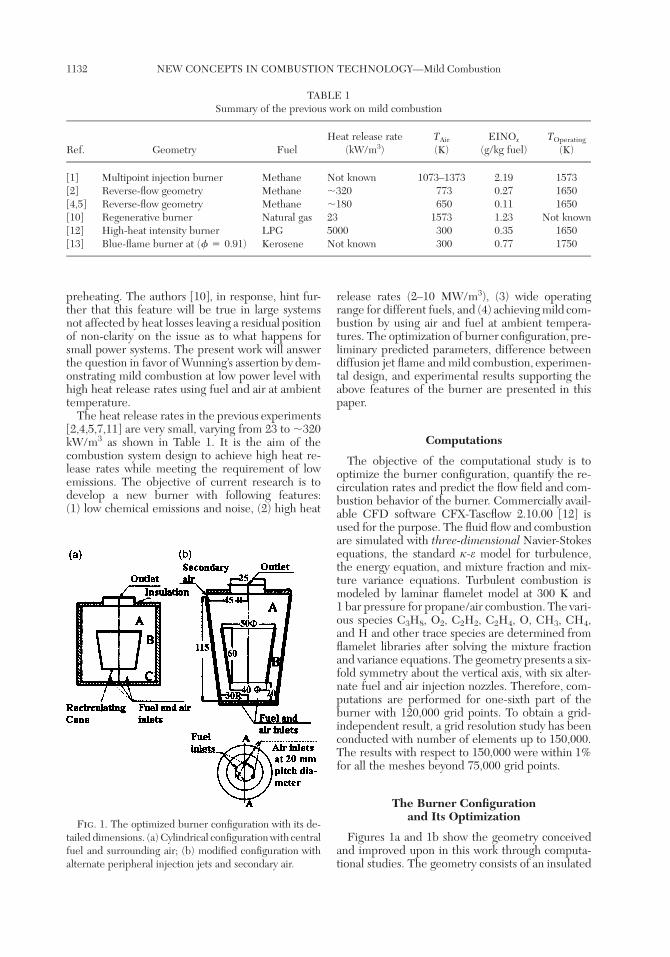
Fig. 2. Variation of recirculation rate variation with thelength of the recirculating cone. The bottom position isfixed at 20 mm from injection plane, and the top length isvaried to optimize the configuration.
Fig. 3. Predicted velocity plots in the burner at differentx, y locations in the burner. The velocity scale is shown onthe right side. The arrows indicate the position of fuel (F)and air (A) injection.
cylinder (with 25 mm thick ceramic wool) with fueland air injection from the bottom holes arrangedaround the periphery of a circle. The outlet is at thetop. A thin conical object—frustum of a cone (madeof metal here, but could be replaced by a ceramicmaterial in practice) with space at the bottom andthe top—is placed so that fluid can move from regionA to region C through region B (refer to Fig. 1a).The size and shape of the conical object were settledby a large number of computational studies to de-termine the nature and the shape of the recirculationzones. In the first instance, the need for the cone
itself was established when it was found that the fluidwas recirculating in the top region with a smallamount of fluid coming into the bottom area; thiswould not help in creating the favorable conditionsfor mild combustion. The presence of the conicalobject helped in drawing the hot gases from the topthrough the side region, the suction for which wasprovided by the high-speed jets of fuel and air ar-ranged at the bottom. The recirculation ratio is theratio of the amount of hot gases entering via B tothe sum of the flow rates of fuel and air. The velocityand density profiles in the zone B are used to obtainthe mass flow rate entering the bottom zone fromthe sides.
Initial trials with central fuel and surrounding airarrangement showed that the high-speed fuel jeteasily escaped from the burner with incompletecombustion, and the recirculating products con-tained large oxidizer fraction. To achieve completecombustion and effective recirculation, combina-tions of central air, surrounding multiple fuel jets,and alternate peripheral air and fuel jets were ex-plored. After this study [11], it was found that therequired effective recirculation could be obtainedwith alternate peripheral jets (at 20 mm pitch di-ameter in this case, but suitable dimensions at otherpower levels); this also controlled the choice of theoutlet diameter.
The computational study showed dead recirculat-ing zones at the corners at the bottom. Hence, thegeometry was further improved by eliminating thezones at C in Fig. 1a into a conical geometry asshown in Fig. 1b. A 11� angle is selected for recir-culating cone after a number of calculations aimedat reducing the dead zone [11]. Fig. 2 shows thevariation of recirculation ratio with the length of thecone. The recirculation ratio goes through a maxi-mum at 90 mm cone length and varies weakly up to60 mm. The final geometry realized is shown inFig. 1b that shows another interesting feature. Theburner is provided with a facility to operate in stagedcombustion mode with slight excess air (limited to10% of the total) supplied to reduce the CO emis-sions from the burner [11]. In this mode, 75% of theair is supplied through the primary jets coplanar tofuel jets, with the remaining air supplied in the topregion. This burns up the residual CO.
Figure 3 shows the computed velocities in theburner for the case of 80 mm cone height. The fueland air jets appear to lose their identity at a heightjust above the inner cone. The negative velocities areindicative of the reverse flow. Air flow dominates theflow field since the air-to-fuel momentum ratio islarge, �18.
Mild Combustion and Current Burner
On examination of the literature, it was noted thatflameless combustion was defined qualitatively. It
1134 NEW CONCEPTS IN COMBUSTION TECHNOLOGY—Mild Combustion
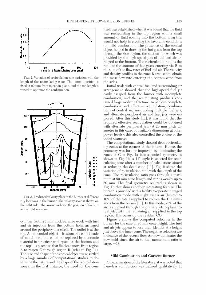
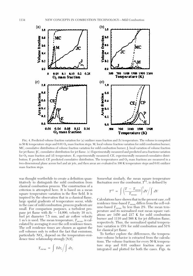
Fig. 4. Predicted volume fraction variation for (a) oxidizer mass fraction and (b) temperature. The volume is computedin 50 K temperature steps and 0.01 O2 mass fraction steps. M, local volume fraction variation for mild combustion burner;MC, cumulative distribution of volume fraction variation for mild combustion burner; J, local variation of volume fractionfor jet flame; JC, cumulative distribution for jet flame. (c) Experimentally measured and predicted area fractions variationfor O2 mass fraction and (d) temperature. E, experimentally measured; CE, experimentally measured cumulative distri-bution; P, predicted; CP, predicted cumulative distribution. The temperatures and O2 mass fractions are measured in atwo-dimensional plane across fuel and air jets, and then areas are evaluated in 100 K temperature steps and 0.01 oxidizermass fraction steps.
was thought worthwhile to create a definition quan-titatively to distinguish the mild combustion fromclassical combustion process. The construction of acriterion is attempted here. It is based on a meansquare temperature variation in the flow field. It isinspired by the observation that in a classical flame,large spatial gradients of temperature occur, whilein the case of mild combustion, process gradients aresmall. For comparison purposes, a turbulent pro-pane jet flame with Re � 14,000, velocity 10 m/s,fuel jet diameter 7.5 mm, and air coflow velocity1 m/s is used. The mean temperature, Tmean, is cal-culated by averaging it over the cell residence times.The cell residence times are chosen as against thecell volumes only to reflect the fact that emissions,particularly NOx, depend on the temperature-resi-dence time relationship strongly [8,9].
T � Tds dsmean r r� ��
Somewhat similarly, the mean square temperaturefluctuation over the combustor, T�2, is defined by
2T � Tmean2T� � dV dV� � � ��Tmean
Calculations have shown that in the present case, cellresidence time-based Tmean differs from the cell-vol-ume-based Tmean by less than 2%. The mean tem-perature and its normalized root mean square vari-ations are 1450 and 217 K for mild combustionburner and 1110 and 566 K for jet diffusion flame,respectively. Thus, the normalized spatial tempera-ture variation is 15% for mild combustion and 51%for classical jet flame.
To further explore the differences, the tempera-ture-volume behavior is extracted from the calcula-tions. The volume fractions for every 50 K tempera-ture step and 0.01 oxidizer fraction steps areintegrated and plotted for both the cases. Figs. 4a
HIGH-INTENSITY LOW-EMISSION BURNER 1135
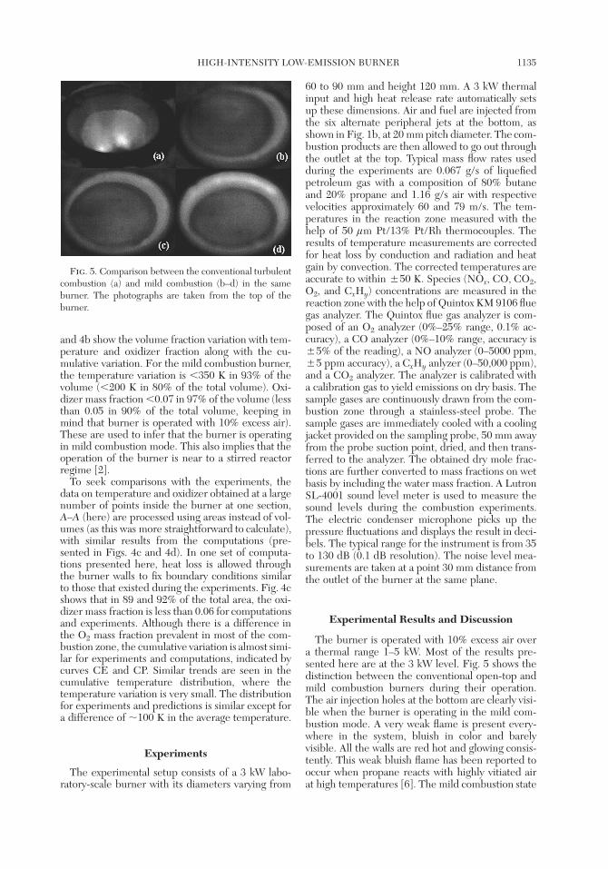
Fig. 5. Comparison between the conventional turbulentcombustion (a) and mild combustion (b–d) in the sameburner. The photographs are taken from the top of theburner.
and 4b show the volume fraction variation with tem-perature and oxidizer fraction along with the cu-mulative variation. For the mild combustion burner,the temperature variation is �350 K in 93% of thevolume (�200 K in 80% of the total volume). Oxi-dizer mass fraction �0.07 in 97% of the volume (lessthan 0.05 in 90% of the total volume, keeping inmind that burner is operated with 10% excess air).These are used to infer that the burner is operatingin mild combustion mode. This also implies that theoperation of the burner is near to a stirred reactorregime [2].
To seek comparisons with the experiments, thedata on temperature and oxidizer obtained at a largenumber of points inside the burner at one section,A–A (here) are processed using areas instead of vol-umes (as this was more straightforward to calculate),with similar results from the computations (pre-sented in Figs. 4c and 4d). In one set of computa-tions presented here, heat loss is allowed throughthe burner walls to fix boundary conditions similarto those that existed during the experiments. Fig. 4cshows that in 89 and 92% of the total area, the oxi-dizer mass fraction is less than 0.06 for computationsand experiments. Although there is a difference inthe O2 mass fraction prevalent in most of the com-bustion zone, the cumulative variation is almost simi-lar for experiments and computations, indicated bycurves CE and CP. Similar trends are seen in thecumulative temperature distribution, where thetemperature variation is very small. The distributionfor experiments and predictions is similar except fora difference of �100 K in the average temperature.
Experiments
The experimental setup consists of a 3 kW labo-ratory-scale burner with its diameters varying from
60 to 90 mm and height 120 mm. A 3 kW thermalinput and high heat release rate automatically setsup these dimensions. Air and fuel are injected fromthe six alternate peripheral jets at the bottom, asshown in Fig. 1b, at 20 mm pitch diameter. The com-bustion products are then allowed to go out throughthe outlet at the top. Typical mass flow rates usedduring the experiments are 0.067 g/s of liquefiedpetroleum gas with a composition of 80% butaneand 20% propane and 1.16 g/s air with respectivevelocities approximately 60 and 79 m/s. The tem-peratures in the reaction zone measured with thehelp of 50 lm Pt/13% Pt/Rh thermocouples. Theresults of temperature measurements are correctedfor heat loss by conduction and radiation and heatgain by convection. The corrected temperatures areaccurate to within �50 K. Species (NOx, CO, CO2,O2, and CxHy) concentrations are measured in thereaction zone with the help of Quintox KM 9106 fluegas analyzer. The Quintox flue gas analyzer is com-posed of an O2 analyzer (0%–25% range, 0.1% ac-curacy), a CO analyzer (0%–10% range, accuracy is�5% of the reading), a NO analyzer (0–5000 ppm,�5 ppm accuracy), a CxHy anlyzer (0–50,000 ppm),and a CO2 analyzer. The analyzer is calibrated witha calibration gas to yield emissions on dry basis. Thesample gases are continuously drawn from the com-bustion zone through a stainless-steel probe. Thesample gases are immediately cooled with a coolingjacket provided on the sampling probe, 50 mm awayfrom the probe suction point, dried, and then trans-ferred to the analyzer. The obtained dry mole frac-tions are further converted to mass fractions on wetbasis by including the water mass fraction. A LutronSL-4001 sound level meter is used to measure thesound levels during the combustion experiments.The electric condenser microphone picks up thepressure fluctuations and displays the result in deci-bels. The typical range for the instrument is from 35to 130 dB (0.1 dB resolution). The noise level mea-surements are taken at a point 30 mm distance fromthe outlet of the burner at the same plane.
Experimental Results and Discussion
The burner is operated with 10% excess air overa thermal range 1–5 kW. Most of the results pre-sented here are at the 3 kW level. Fig. 5 shows thedistinction between the conventional open-top andmild combustion burners during their operation.The air injection holes at the bottom are clearly visi-ble when the burner is operating in the mild com-bustion mode. A very weak flame is present every-where in the system, bluish in color and barelyvisible. All the walls are red hot and glowing consis-tently. This weak bluish flame has been reported tooccur when propane reacts with highly vitiated airat high temperatures [6]. The mild combustion state
1136 NEW CONCEPTS IN COMBUSTION TECHNOLOGY—Mild Combustion
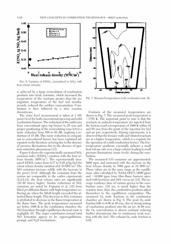
Fig. 6. Variation of EINOx (normalized to NO2) withheat release intensity.
Fig. 7. Measured temperatures in the combustion zone (K).
is achieved by a large recirculation of combustionproducts into fresh reactants, which increased thetemperature of the reactants greater than the au-toignition temperature of the fuel and simulta-neously reduced the oxidizer concentration. Com-bustion is then followed by a slow reactiondownstream.
The noise level measurement is taken at 1 kWpower level for both conventional open-top and mildcombustion burners. The reduction of the outlet sizefrom conventional open top burner to 25 mm andproper positioning of the recirculating cone led to anoise reduction from 100 to 85 dB, implying a re-duction of 15 dB. This noise reduction in compari-son to conventional burner has been explained ad-equately in the literature as being due to the absenceof pressure fluctuations due to the absence of igni-tion-extinction phenomena [13].
Figure 6 shows the experimentally measured NOxemission index (EINOx) variation with the heat re-lease density (MW/m3). The experimentally mea-sured EINOx varies from 0.17 to 0.28 g/kg fuel fora heat release density variation of 2–10 MW/m3. TheNO emissions increase mildly with the increase inthe power level. Although the emissions from thesystem are comparable to the earlier experiments[2,4,5,14], the heat release rates are significantly(10–50 times) higher. Similar reductions of NOxemissions are noted by Fujimori et al. [15] fromlifted jet diffusion flames with high-temperature co-flowing air, when the liftoff height exceeded the at-tached flame length. This decrease in NOx emissionsis attributed to decrease in the flame temperature atthe flame base. The peak temperatures measuredare below 1800 K in the combustion chamber; theNO formation through equilibrium thermal route isnegligible [6]. The major contributors toward totalNO formation appear to be superequilibrium,prompt, and N2O mechanisms.
Contours of the measured temperatures areshown in Fig. 7. The measured peak temperature is�1750 K. The important point to note is that thereactants at ambient temperature are injected fromthe bottom reach a temperature of 1000 K within 10and 50 mm from the point of the injection for fueland air jets, respectively. During experiments, it isobserved that the furnace walls and vitiated reactantsare at a higher temperature, which is a requisite forthe operation of a mild combustion burner. The low-temperature gradients essentially indicate a smallheat release rate over a large volume leading to smallpressure fluctuations (noise levels) during the com-bustion.
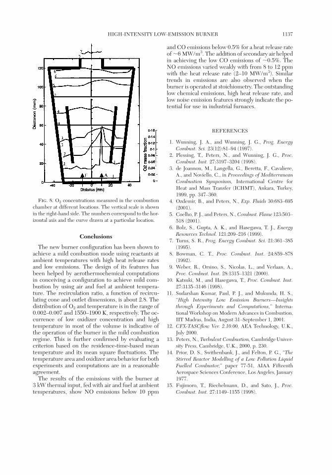
The measured CO emissions are approximately5000 ppm and increased with the increase in theheat release density to 7000 ppm at 10 MW/m3.These values are in the same range as the equilib-rium value calculated by NASA-SP273 (4600 ppm)and �10,000 ppm from blue-flame burners oper-ated with kerosene and 10% excess air [14]. The av-erage residence time of various species in the com-bustion zone, 132 ms, is much higher than thereaction time; thus, the combustion products adjustthemselves to the equilibrium composition. Themeasured O2 mole fractions in the combustionchamber are shown in Fig. 8. The peak O2 molefraction falls to 0.06 at 40 mm, due to strong mixingof combustion products into the air jet. At 60 mm,the O2 concentration is almost constant reducingfurther downstream due to continuous weak reac-tion with the fuel. The exhaust O2 mole fraction is0.02.
HIGH-INTENSITY LOW-EMISSION BURNER 1137
Fig. 8. O2 concentrations measured in the combustionchamber at different locations. The vertical scale is shownin the right-hand side. The numbers correspond to the hor-izontal axis and the curve drawn at a particular location.
Conclusions
The new burner configuration has been shown toachieve a mild combustion mode using reactants atambient temperatures with high heat release ratesand low emissions. The design of its features hasbeen helped by aerothermochemical computationsin conceiving a configuration to achieve mild com-bustion by using air and fuel at ambient tempera-ture. The recirculation ratio, a function of recircu-lating cone and outlet dimensions, is about 2.8. Thedistribution of O2 and temperature is in the range of0.002–0.007 and 1550–1900 K, respectively. The oc-currence of low oxidizer concentration and hightemperature in most of the volume is indicative ofthe operation of the burner in the mild combustionregime. This is further confirmed by evaluating acriterion based on the residence-time-based meantemperature and its mean square fluctuations. Thetemperature area and oxidizer area behavior for bothexperiments and computations are in a reasonableagreement.
The results of the emissions with the burner at3 kW thermal input, fed with air and fuel at ambienttemperatures, show NO emissions below 10 ppm
and CO emissions below 0.5% for a heat release rateof �6 MW/m3. The addition of secondary air helpedin achieving the low CO emissions of �0.5%. TheNO emissions varied weakly with from 8 to 12 ppmwith the heat release rate (2–10 MW/m3). Similartrends in emissions are also observed when theburner is operated at stoichiometry. The outstandinglow chemical emissions, high heat release rate, andlow noise emission features strongly indicate the po-tential for use in industrial furnaces.
REFERENCES
1. Wunning, J. A., and Wunning, J. G., Prog. EnergyCombust. Sci. 23(12):81–94 (1997).
2. Plessing, T., Peters, N., and Wunning, J. G., Proc.Combust. Inst. 27:3197–3204 (1998).
3. de Joannon, M., Langella, G., Beretta, F., Cavaliere,A., and Noviello, C., in Proceedings of MediterraneanCombustion Symposium, International Centre forHeat and Mass Transfer (ICHMT), Ankara, Turkey,1999, pp. 347–360.
4. Ozdemir, B., and Peters, N., Exp. Fluids 30:683–695(2001).
5. Coelho, P. J., and Peters, N., Combust. Flame 123:503–518 (2001).
6. Bolz, S., Gupta, A. K., and Hasegawa, T. J., EnergyResources Technol. 121:209–216 (1999).
7. Turns, S. R., Prog. Energy Combust. Sci. 21:361–385(1995).
8. Bowman, C. T., Proc. Combust. Inst. 24:859–878(1992).
9. Weber, R., Orsino, S., Nicolas, L., and Verlaan, A.,Proc. Combust. Inst. 28:1315–1321 (2000).
10. Katsuki, M., and Hasegawa, T., Proc. Combust. Inst.27:3135–3146 (1998).
11. Sudarshan Kumar, Paul, P. J., and Mukunda, H. S.,‘‘High Intensity Low Emission Burners—Insightsthrough Experiments and Computations,’’ Interna-tional Workshop on Modern Advances in Combustion,IIT Madras, India, August 31–September 1, 2001.
12. CFX-TASCflow Ver. 2.10.00, AEA Technology, U.K.,July 2000.
13. Peters, N., Turbulent Combustion, Cambridge Univer-sity Press, Cambridge, U.K., 2000, p. 230.
14. Prior, D. S., Swithenbank, J., and Felton, P. G., ‘‘TheStirred Reactor Modelling of a Low Pollution LiquidFuelled Combustor,’’ paper 77-51, AIAA FifteenthAerospace Sciences Conference, Los Angeles, January1977.
15. Fujimoro, T., Riechelmann, D., and Sato, J., Proc.Combust. Inst. 27:1149–1155 (1998).