student's guide - dcu.iea).pdf · experiment 2 - thin cylinder with closed ends analysis of...
TRANSCRIPT

STUDENT'S GUIDE
e TQ Education and Training Ltd 2000
No part of this publication may be reproduced or transmitted inany form or by any means, electronic or mechanical, includingphotocopy, recording or any information storage and retrievalsystem without the express permission of TQ Education andTraining Limited.
All due care has been taken to ensure that the contents of thismanual are accurate and up to date. However, if any errors arediscovered please inform TQ so the problem may be rectified.
A Packing Contents List is supplied with the equipment. Carefullycheck the contents of the package(s) against the list. If any itemsare missing or damaged, contact your local TQ agent or TQimmediately.
TQ Edu~ation and Training LtdProducts Division

ContentsSection Page
1 INTRODUCTION
1233
DescriptionComputer ConnectionStrain SensorsHow to set up the equipment
2 EXPERIMENTS 5
57999
1010131515
Background and Introduction to the ExperimentsExperiment 1 - Thin Cylinder with Open Ends
Analysis of ResultsThe Stress Strain RelationshipConclusionThe Ratio of Hoop Strain to Longitudinal Strain in an Open CylinderPrinciple Strains and The Mohr's Circle
Experiment 2 - Thin Cylinder with Closed ends
Analysis of ResultsUsing the Method of Superposition to Find the Principle Strains
SOFTWARE OPERATION3 17
17171718181919191920202121
The Main PageThe Menu BarThe Tool Bar
Menu Bar OptionsShort cut KeysUsing the Software
To zero all the gaugesTo take a set of readingsTo display the data tableTo display a graphPlotting Graphs using the SM1 007 SoftwareTo change the experimentNormal Operation
4 THEORY 23
APPENDIX 27
Nomenclature 27

SECTION 1.0 INTRODUCTION
This guide describes how to set up and perfonn several experiments related to the stress systems in a thin cylinder. Itclearly demonstrates the principles involved and gives practical support to your studies. The derivation of the theoryrelated to the stress systems in a thin cylinder is given in section 4. You should read this prior to completing theexperiments and use it as a reference when analysing your results.
Figure 1
Description
Figure 1 shows the SMlOO7 Thin Cylinder apparatus. It consists of a thin walled aluminium cylinder of 80 mm insidediameter and 3 mm wall. Operating the hydraulic pump pressurises the cylinder with oil.
The cylinder has six sensors on its surface that measure strain. A mechanical gauge and electronic sensor measure thehydraulic pressure in the cylinder. The cylinder is held in a sturdy frame in which it is free to move along its axis.Thestrains (and thus the stress) can be measured with the cylinder in two configurations:
"Open" ends - where the axial loads are taken by the frame (not the cylinder), therefore there is no direct axial stress
2. "Closed" ends - where the axial loads are taken by the cylinder, therefore there must be direct axial stress
The two configurations are achieved using the large hand wheel at the end of the frame.
In the Open ends condition the hand wheel is screwed fully in. This pushes the two pistons away from the cylinder endcaps so that there is no contact between them. Therefore, the axial force is transmitted from the pressurised oil into theframe rather than the cylinder. See Figure 2.
In the Closed ends condition the hand wheel is wound out. This allows the pistons to move outward against the cylinderend caps so that there is no contact with the frame. Therefore the axial force is transmitted from the pressurised oil intothe cylinder itself. See Figure 3.

Thin Cylinder. Student Guide
Pistons(toud1ing frame)
I"',-m
Path of loadFrame Gap
Figure 2 Open Ends Condition.
n
..Platona(bJd1W'O end cepe)
n
r:
1
~Frame
1Figure 3 Closed Ends Condition
Computer Connection
To take and record readings and plot graphs, the SMlOO7 must be connected to a PC. Dedicated software and theconnecting lead is supplied with the SMlOO7.
Page 2

SM1007 Thin Cylinder. Student Guide
Strain Sensors
The sensor used to measure the strains in the walls of the thin cylinder is called a Strain Gauge.
Strain gauges are sensors that experience a change in electrical resistance when they are stretched or compressed, thischange in resistance can be shown in terms of displacement (strain). Strain gauges are made from a metal foil cut in azigzag pattern, they are only a few microns thick so they are mounted on a backing sheet, this allows them to be handledand electrically insulates the zigzag element. Gauges are bonded to the structural part under examination, thus the straingauge stretches and compresses the same amount as the surface of the part. To give an direct reading of strain we use aconstant called the gauge factor, this is to compensate for the slight differences in manufacture between each batch ofgauges, it usually varies between 1.8 and 2.2. It is usual to set this in the strain gauge readout.
There are six strain gauges on the cylinder, arranged at various angles to allow the study of how the strain varies atdifferent angles to the axis. Strains are shown on the P.C. screen, directly in microstrain on a schematic of the thincylinder. Note that a negative reading is a compressive strain and a positive reading is a tensile strain
The technique of strain gauging is of great importance to structural engineers. This equipment gives you the opportunityto understand their use.
How to set up the equipment
Cylinder---
~
Figure 4 Layout of the SM1007
Before using the equipment, always:
Visually inspect all parts, including electrical leads, for damage or wear.
Check that all electrical connections and other parts are secured correctly and fastenings are sufficiently tight.
Position the equipment safely on a solid, level surface, so that it is steady, easily accessible.
Never apply excessive loads to any part of the equipment.
In all of the experiments. the basic set up of the equipment is the same. Refer to the relevant section for the specificinformation you will require to do each experiment.
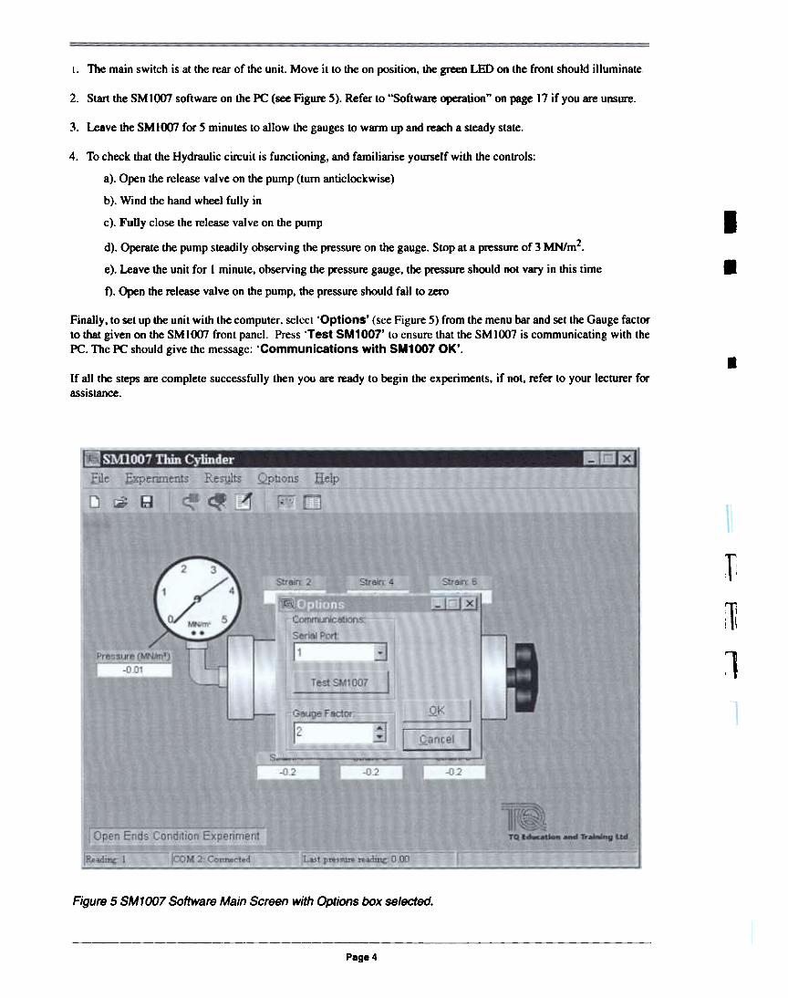
I. The main switch is at the rear of the unit. Move it to the on position. the green LED on the front should illuminate.
2. Start the SM 1007 software on the PC (see Figure 5). Refer to "Software operation" on page 17 if you are unsure.
3. Leave the SMl007 for 5 minutes to allow the gauges to WarD) up and reach a steady state.
I
4. To check that the Hydraulic circuit is functioning, and familiarise yourself with the controls:
a). Open the release valve on the pump (turn anticlockwise)
b). Wind the hand wheel fully in
c). Fully close the release valve on the pump
.d). Operate the pump steadily observing the pressure on the gauge. Stop at a pressure of 3 MN/m2.
e). Leave the unit for I minute. observing the pressure gauge. the pressure should not vary in this time
f). Open the release valve on the pump. the pressure should fall to zero
Finally, to set up the unit with the computer, select 'Options' (see Figure 5) from the menu bar and set the Gauge factorto that given on the SMIOO7 front panel. Press 'Test SM1007' to ensure that the SMlOO7 is communicating with thePC. The PC should give the message: 'Communications with SM1007 OK'. .If all the steps are complete successfully then you are ready to begin the experiments, if not, refer to your lecturer forassistance.
f\
:~
1
Figure 5 SM1007 Software Main Screen with Options box selected.
Page 4
SECTION 2.0 EXPERIMENTS
Background and Introduction to the Experiments
In relation to stress analysis, cylinders are divided into two groups: thick and thin. The distinction between the tworelates to the ratio of internal diameter to wall thickness of a particular cylinder. A cylinder with a diameter to thicknessratio of more than 20 is considered to be thin. A ratio of less than 20 is considered to be thick. This distinction is madeas the analysis of a cylinder can be simplified by assuming it is thin. The SMlOO7 cylinder has a ratio of approximately27, which is well above the ratio for being considered thin.
Thin cylinders, or shells are commonplace in engineering. Examples of thin walled cylinders are:
. pressure pipes,
. aircraft fuselages and
. compressed gas containers.
Thick walled cylinders are less common, an example being a gun barrel.
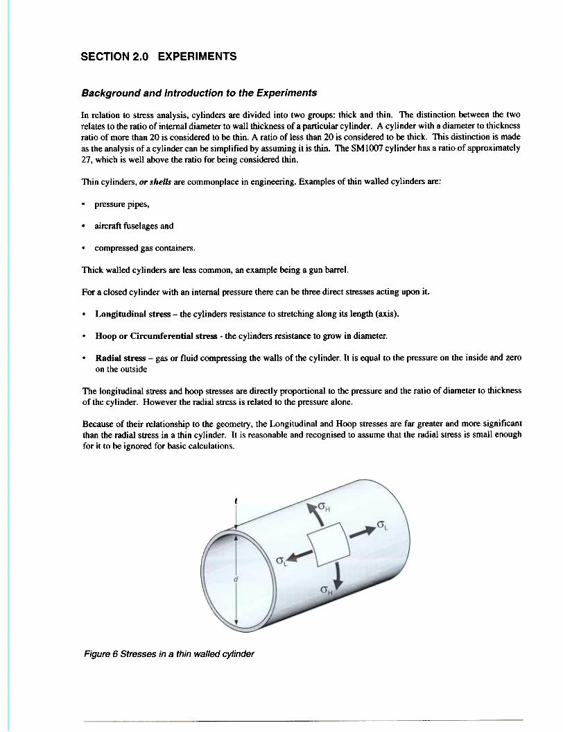
For a closed cylinder with an internal pressure there can be three direct stresses acting upon it.
. Longitudinal stress - the cylinders resistance to stretching along its length (axis).
. Hoop or Circumferential stre~ - the cylinders resistance to grow in diameter.
. Radial stress - gas or fluid compressing the walls of the cylinder. It is equal to the pressure on the inside and zeroon the outside
The longitudinal stress and hoop stresses are directly proportional to the pressure and the ratio of diameter to thicknessof the cylinder. However the radial stress is related to the pressure alone.
Because of their relationship to the geometry, the Longitudinal and Hoop stresses are far greater and more significantthan the radial stress in a thin cylinder. It is reasonable and recognised to assume that the radial stress is small enoughfor it to be ignored for basic calculations.
~
Figure 6 Stresses in a thin walled cylinder

~O7 Thin Cylinder - Student Guide
The individual direct sb'esses are given by
0' H = pd/2t and
O'L = pdl4t
Where:
O'H = Hoop Sb'eSS (Nm-2
aL = Longitudinal Stress (Nm-2
p = Pressure in the cylinder (Nm-1
d = Diameter of the cylinder (m:
t = Thickness of cylinder walls (m)
Nearly all applications of the thin cylinder will have closed ends with the biaxial stress system described previously.However as outlined in the introduction, the equipment allows us to examine the stresses in the cylinder with open endsi.e. with no direct longitudinal stress. Although there is no practical applications for a cylinder in this condition, theexperiment yields several useful relationships. We can use these relationships in the more complex closed endscondition.
Page 6

SM1007 Thin Cylinder. Student Guide
Experiment 1 - Thin Cylinder with Open Ends
In this experiment we will pressurise the cylinder in the open ends condition taking readings from all six strain gauges,we will then analyse the results in various ways to establish some important relationships. Examine the cylinder and thediagram on the front panel (or Figure 7) to understand the notation and placement of the strain gauges in relation to theaxis of the cylinder. The experimental method utilises the SMlOO7 software to display and take readings. A guide to
using the software is given in section 3.
-
-
~
nFigure 7 Positions of the strain gauges.
~
.I I. Having set up and familiarised yourself with the equipment by following the instructions in section 1, open thepump release valve and screw in the hand wheel to set up the open ends condition.
:82. In the SMlOO7 software choose 'Open Ends Condition' from the 'Experiments' menu option. Then connect to
the SMlOO7 unit by selecting 'Connect to SM1007' from the same menu. The virtual meters on the screenshould now display values of pressure and strain.-
If the 'Disconnect the SM1007' from the 'Experiments' menu option was notselected the last time the equipment was used, the software may prompt you to
disconnect and then reconnect again when you change the experiment from closed to
open (or the other way round).
NOn ~n
~
3. Close the pump release valve and zero the readings by selecting 'Zero All Gauges' from the 'Experiments'menu option. All the virtual strain meters should now read 0:10.3 J.1E, and the pressure meter should read 0:1:0.01MN -2
m .
4. Take the first set of readings (at zero) into the data table by selecting 'Record Gauge Readings' from the'Experiments' menu option. Display the data table by selecting 'Data Table' in the 'Results' menu.
5. Pump the handle slowly until a pressure of around 0.5 MNm-2 and record the readings into the data table again byselecting 'Record Gauge Readings' from the 'Experiments' menu option. Wait a few seconds between pumpsfor the gauges to stabilize.
8'

007 Thin Cylinder. Student Guide
6. Carefully increase the pressure in 0.5 MNm-2 increments, recording the readings into the data table until you have
reached a value of 3 MNm-2.
WARNING ~ Do not exceed a cylinder pressure of 3.5 MNmo2
Try to get as close as possible to 3 MNm-2 as it will allow you to make direct comparisons with established theoreticalvalues at this pressure.
7. You may print the data table if desired by pressing the printer button in the top left comer of the table.
8. Disconnect the communicalions between the PC and the apparatus by selecting 'Disconnect the SM1007' fromthe 'Experiments' menu option.
.
riil ':
1
1
Page 8

SM1007 Thin Cylinder. Student Guide
Analysis of Results
The Stress Strain Relationship
The data table calculates the hoop stress for each pressure reading. Select one pressure reading (other than zero) andcheck the calculation of stress using the equations given in the previous section and the data on the front panel of theSMlOO7.
From your examination of the positioning of the strain gauges you will have noticed that gauges 1 and 6 have been placedso that they are measuring the hoop strain in the cylinder. Examine the results for gauges 1 and 6, what can you say aboutthe magnitude of the hoop strain as you move along the axis of the cylinder?
You should conclude that the hoop strain remains constant along the length of the cylinder.
Plot a graph of Average Hoop Stress versus Hoop Strain either by hand (from the data table), or by using the graphingfacility in the SMlOO7.
To plot the graph using the SMlOO7 software. select 'Hoop Stress v Hoop Strain' from the 'Results' menu option.A chart wi" appear with crosses marking the results.
What is the relationship between stress and strain?
Your graph should reveal a linear relationship between stress and strain. the gradient of which is a measure of stiffnesscalled the Youngs's Modulus.
Eade
Where:
E = Young's Modulus (Nm-2)
0" = Stress (Nm-2)
E = Strain (~)
Find a value of the Young's Modulus for the cylinder material from your graph.
To find the value of the gradient and therefore the Youngs Modulus from the graph plotted by the software, a line needsto be drawn through the results. The slope of the line is indicated when you release the mouse button. (Refer to "PlottingGraphs using the SMlOO7 Software" on page 20)
The Young's Modulus varies from material to material, but is a constant for each material, so long as it has unifonnproperties (homogenous and isotropic). For the aluminium alloy used for the SM I 007 cylinder the Young's modulus isnominally 70 GNm-2 Does the value of Young's modulus from your graph agree with the theoretical value stated? Ifthere is a discrepancy between the values then name any sources of error that may be present.
Steel is approximately three times stiffer than aluminium having a Young's Modulus of 210 GNm-2.
If the cylinder had been made of steel would the measured strain be higher or lower for the same stress?
Conclusion
The use of the apparatus has established the stress strain relationship and experimental value of Young's Modulus. Notethat since the Young's Modulus remains constant for any given homogenous isotropic material, strain gauges are areliable means of measuring stress on the surface of a structural part.

7 Thin Cylinder. Student Guide
The Ratio of Hoop Strain to Longitudinal Strain in an Open Cylinder
In the introduction to the experiments it was stated that there is no Direct longitudinal strain in the open ends conditions.
With reference to the small diagram on the front of the SM 1 007, identify the gauge which measures the longitudinalstrain. Does this gauge register zero?
You will find that the gauge does not register zero, in fact a significant compressive strain is measured. This is becausethere is an Indirect Longitudinal strain which is a result of the hoop stress. This indirect strain is generated by the factthat as the cylinder increases diameter the length decreases (the opposite can be seen to occur if you stretch an elasticband)
To explore this relationship, plot a graph of the Longitudinal Strain Versus Average Hoop Strain, either by hand (fromthe data table), or by using the graphing facility in the SMlOO7.
To plot the graph using the SM I 007 software, select Longitudinal v Hoop Strain from the Results menu. A chartwill appear with crosses marking the results.
Find the gradient of your plot.
To find the value of the gradient from the graph plotted by the software, a line needs to be drawn through the results. Theslope of the line (gradient) is indicated when you release the mouse button. (Refer to "Plotting Graphs using the SM1OO7Software" on page 20)
The magnitude of the gradient of your plot is a called Poisson's ratio it can be defined as the ratio of indirect strain todirect strain. In mathematical terms it is given as:
v = -eI.JeHo
where
v = Poisson's Ratio
ELo = Longitudinal Strain (in the open ends condition)
EHo = Hoop Strain (in the open ends condition)
The Poisson's ratio changes from material to material but is constant for any given homogenous isotropic material.
Most metals have a value of Poisson' s ratio of around 0.3. although the range of values is 0.1 to 0.5 the extremes beingconcrete and rubber respectively.
The cylinder is manufactured from an aluminium alloy which has a Poisson's ratio of 0.33. Compare this to the gradientof your graph.
Principle Strains and The Mohr's Circle
In the case of a cylinder the maximum and minimum strains are always at right angles to each other (see the theorysection) These strains are called the principle strains. As discovered previously, in the open ends condition, the thincylinder has principle strains of:
EHo = uHJE (direct from the hoop stress)
ELo = -vO'HoIE (indirectly due to the Poisson effoct)
But how to we quantify strains at other than right angles to the axis of the cylinder?
The answer lies in a simple yet effective graphical method known as a Mohr's Circle. Mohr's circles can be u~ tosolve a variety of strain, stress and deflection problems.
Page 10

SM1007 Thin Cylinder. Student Guide
First. construct a Mohr's Circle by hand so that you understand how the method works. The 8M 1007 software will alsoconstruct a Mohr's circle from your results. You can use this facility to check your work.
We have already established that the strain gauges give a very linear response to pressure so we will use only the values
for the maximum test pressure (3 MNm-2).
1. On graph paper construct an axis which allows for the minimum principle strain (gauge 2) and the maximumprinciple strain (the average of gauges 1 and 6) on the x axis and a strain of around -400 to +400 on the y axis. Thex and y axes must be to the same scale.
2. As can be seen from the equations in the theory section, on a Mohr's Circle the strains are related to 29 where 9 =the angle from the axis. This is an important thing to remember.
Since gauge 2 is on the axis of the cylinder, then the angle is 0° on the Mohr's circleSince gauges I and 6 are 90° from the axis, then the angle is 180° on the Mohr's circle
3. Plot these 2 points on the axis as shown in sketch 1
go-
Figure 8 Sketch 1
4. The two points are the extremes of the Mohr's circle. On this basis find the centre either by calculation or byconstruction, then draw a circle as shown in sketch 2.
This is the Mohrs circle based on your results for the principle strains. You can now use this to find the direct strain
at any angle from the ws.
5. To find the direct strain at 60° from the axis, draw a line from the centre of the circle at 120° clockwise from 0°(remember, twice the angle!) until it intersects the circle, then draw a line vertically down to the x axis (see Figure
10).
6. Read off the value of strain and compare this to the reading for the strain gauge which is placed at 60° from the axi!(gauge 5) you should find that the two readings are in close agreement.
7. Repeat the process for 30° and 45° and compare the readings from your Mohr's Circle to those measured on theequipment. Does the Mohr's circle accurately predict the direct ~train at any angle?
As you know, the x axis on the Mohr's circle plot is the direct strain, but what is the y axis?

The answer is the shear strain, from which we can quantify the shear stress
Figure 9 Sketch 2
1
Figure 10 Sketch 3
To plot the Mohr's circle using the SMlOO7 software, select Plot Mohr's Circle from the Results menu. A chart willappear with crosses marking the results. Refer to "To display a graph" on page 20 for extra functions on the Mohr'scircle. Readings of strain may be taken from the graph by moving the mouse CUTSOf' around the circle.
Find the values of shear strain for each of the angles on the cylinder in the same way you found the direct strain. At what
angle is the maximum shear strain? Will it always be this angle for a thin cylinder?
Calculate theoretical principle strains (using the equations ~iven in the theory section) with a pressure of 3 MNm-2, aPoisson's ratio of 0.33 and a Young's Modulus of 69 MNm- . Construct a Mohr's circle using these values and compareit to your experimental one. Do the theoretical and experimental Mohr's circles agree? What are the sources of error?
Page 12

SM1007 Thin Cylinder. Student Guide
Experiment 2 - Thin Cylinder with Closed ends
Having completed the analysis of the open ends condition we will now test the cylinder taking the same readings as inexperiment 1 but with the cylinder in the closed ends condition to show the effect of the biaxial stress system.
. Open the pump release valve and carefully unscrew the hand wheel enough to set up the closed ends condition.
NOTE ~ The handwheel is not fastened to the apparatus, if it is unscrewed too far, it will fall
out.
To check that the frame is not transmitting any load, close the pump release valve and pump the handle and observethe pressure gauge, you may need to pump a number of times as the oil pushes the pistons outward.
2. Once a pressure of around 3 MNm-2 has been achieved, gently push and pull the cylinder along its axis, the cylindershould move in the frame indicating that the frame is nOllransmitting any load. If it doesn't move, wind thehandwheel out some more and try again.
WARNING ~ Do not exceed a cylinder pressure of 3.5 MNm-2
3. In the SMlOO7 software choose 'Closed Ends Condition' from the 'Experiments' menu option. Then connectto the SMlOO7 unit by selecting 'Connect to SM1007' from the same menu. The virtual meters on the screenshould now display values of pressure and strain.
If the 'Disconnect the SM1 007' from the 'Experiments' menu option was not
selected the last time the equipment was used, the software may prompt you to
disconnect and then reconnect again when you change the experiment from closed to
open (or the other way round).
4. Close the pump release valve and zero the readings by selecting 'Zero All Gauges' from the 'Experiments'menu option. All the virtual strain meters should now read 0:!:0.3 ~, and the pressure meter should read O:tO.OlMN -2
m .
5. Take the first set of readings (at zero) into the data table by selecting 'Record Gauge Readings' from the'Experiments' menu option. Display the data table by selecting 'Data Table' in the 'Results' menu.
6. Pump the handle slowly until a pressure of around 0.5 MNm-2 and record the readings into the data table again byselecting 'Record Gauge Readings' from the 'Experiments' menu option. Wait a few seconds between pumpsfor the gauges to stabilize.
7. Carefully increase the pressure in 0.5 MNm-2 increments, recording the readings into the data table until you have
reached a value of 3 MNm-2.
WARNING ~ Do not exceed a cylinder pressure of 3.5 MNm-2

SM1007 Thin Cylinder. Student Guide
Try to get as close as possible to 3 MNm-2 as it will allow you to make direct comparisons with established theoreticalvalues at this pressure.
8. You may print the data table if desired by pressing the printer button in the top left corner of the table.
9. Disconnect the communications between the PC and the apparatus by selecting 'Disconnect the SM1007' fromthe 'Experiments' menu option.
Page 14

SM1007 Thin Cylinder - Student Guide
Analysis of Results
Examine the data table. With reference to the stress equations, confirm that longitudinal stress is half the value of thehoop stress. Check, using a method of differences, or by sketching graphs, that the readings from the gauges are stilllinear in the closed ends condition.
Using the Method of Superposition to Find the Principle Strains
In the previous experiment, we established that for the direct hoop stress we created and indirect longitudinal strain, dueto the Poisson effect. It follows therefore, that if we created a purely longitudinal stress that we would have an indirecthoop strain. If the cylinder were stretched it will have a tendency to reduce in diameter (which is exactly what happensif you stretch an elastic band.) To find the principle strains we can use the idea of superposition. This means that we cansimply work out the principle strains for each stress case (hoop and longitudinal) in isolation and then sum them to givethe principle strains for the biaxial system.
I.e.
"The principle strain in the longitudinal direction is the sum of the direct longitudinal strain and the indirectlongitudinal strain"
and
'The principle strain in the circumfrencial direction is the sum of the direct hoop strain and the indirect hoopstrain."
In mathematical terms
The hoop stress will cause strains of:
EH= O'IIE
£L = -vailE (due to the Poisson effect)
Conversely, the longitudinal stress will cause strains of:
£L= ailE
EN = -vO'LIE (due to the Poisson effect)
The algebraic sum of these strains is
EH= (O"JrvO"IJIE
£L = (O"L-VO"H)/E
Construct a Mohr's circle from your results at 3 MNm-2 either by hand or by using the SM 1007 Software using the samemethod as used in experiment 1.
Read off values for the direct strains and compare them to values obtained from the equipment. Your predicted andexperimental value should be in close agreement. What do you notice about the overall diameter of the Mohr's circlecompared to the open ends condition? How does this affect the shear strain?
Calculate theoretical principle strains using the equations given in the theory section with a pressure of 3 MNm-2, aPoisson's ratio of 0.33 and a Young's Modulus of70 MNm-2. Construct a Mohr's circle using these values and compareit to your experimental one. Do the theoretical and experimental Mohr's circles agree?

SECTION 3.0 SOFTWARE OPERATION
The TQ SMlOO7 Thin Cylinder software only operates on computers which have the WindowsTM Operating System
Currently, WindowsTM 95, 98 and NT4 are supported.
To start the software:
Start the computer and allow the WindowsTM Operating System to load.
2. Click on the TQ SMlOO7 icon or select SM1007 Thin Cylinder from the SM1007 Programs Group.
3. The main page will appear, as in Figure 11 although some of the controls may be greyed out.
Figure 11 TO SM1007 Thin Cylinder Software - Main page
The Main Page
The picture on the main page 'mimics' the actual apparatus. The text boxes around the cylinder are 'virtual meters' whichindicate the reading from each strain gauge and the pressure gauge, they do not respond immediately because thesoftware allows the gauges to stabilize before updating the readings.
The Menu Bar
Along the top of the page is the menu bar. You may click on any of the words in the menu bar to make them drop downinto a list of choices, or you may press the AL T button on your keyboard and at the same time, the letter which is
underlined.
The Tool Bar
Underneath the menu bar is a range of 'tool bar' buttons. The buttons on the tool bar are a user-friendly short cut tocommonly used choices from the menu bar. Hover the mouse cursor over each tool button to discover what action theyperform.
SM1007 Thin Cylinder. Student Guide
Menu Bar Options
The menu bar options allow you to perform the following
FileThis list allows you to open a new or previous file, save the current file or exit the program.
NOTE ~ If the program is exited (closed) before saving the experiment, the data will be lost.
Files are saved by default into the Experiment Files folder under the TQ Software directory of the Program Files in thePC. All experiment files are given the extension *,SM7.
ExperimentsThis list allows you to select Open or Closed ends experiments, connect the communications path to the SMlOO7 ThinCylinder apparatus, set up the gauges and take readings.
ResultsThis list allows you to display the data table and graphs of stress and strain relationships.
Only one graph may be displayed at a time.
When either the data table or graphs are selected from the results option on the menu bar, a new page will open,displaying the data you have selected. Along the top of each new page there are more tool buttons, which allow you toprint the results or graph on the selected printer. The graphs have tool buttons which allow you to display or hide gridlines, modify the graphs or copy the graph to the clipboard of the PC. Hover the mouse cursor over the tool buttons todiscover what action they perform.
OptionsThis allows you to check the communication path to the Thin Cylinder apparatus, calibrate the gauge factor and selectthe COM port on the PC to which the serial communications cable is connected.
1Short cut Keys
On eoch of the drop down menu lists, a short cut key is indicated along side some commands. Pressing the short-cut keyindicated gives a quick one key press method of perfonning those commands.
The short-cut keys in the TQ SMlOO7 software are:
F3 - Connect to SMIOO7
F4 - Disconnect from SMlOO7
FS - Record Gauge Readings
F6 - Remove Last Reading
Page 18

Using the Software
Figure 12 The Tool Buttons.
To set up an experiment, select 'New' from the 'File' menu option, or press the Create New File tool button.
2. Make sure the SMlOO7 apparatus is connected to the PC with the serial cable and that the apparatus is connected tothe mains supply and switched on. The green light next to the serial communication socket on the apparatus shouldbe on.
3. Select 'Options' from the menu bar. Check that the correct COM port is selected and that the gauge factor is set tothe value indicated on the label at the front of the SM 1007 apparatus.
4. Press 'Test SM1 007' to check that the communications are set up correctly. If the communications are faulty or thewrong COM port is selected, the software will indicate an error, stating 'Could not Communicate'. Otherwisethe software will state 'Communication with SM1007 OK'.
5. On the options box, select 'OK' (to save any changes) or 'Cancel' (to discard any changes) and then close the box.
6. Decide which experiment you wish to do and select either 'Open ends Condition' or 'Closed endsCondition' from the 'Experiments' menu.
7. Select 'Connect to SM1007' from the 'Experiments' menu, or press the Connect to SMlOO7 tool button. Thevirtual meters will all display the current values of pressure and strain. The green light next to the serialcommunication socket on the apparatus will start to flash slowly.
8. Conduct the experiments as detailed.
To zero all the gauges
Select 'Zero All Gauges' from the 'Experiments' menu option, or press the Zero All Gauges tool button.
To take a set of readings
Select 'Record Gauge Readings' from the 'Experiments' menu option, or press the Record Gauge Readings toolbutton.
To display the data table
Select 'Display Data Table' from the 'Results' menu option, or press the Display Data Table tool button.
Incorrect readings may be removed by selecting 'Remove Last Reading' or 'Remove All Readings' from the'Experiments' menu option.

SM1007 Thin Cylinder. Student Guide
To display a graph
Select 'Hoop Stress V Hoop Strain'. 'Plot Mohr's Circle', or 'Longitudinal v Hoop Strain' from the'Results' menu option.
The Longitudinal v Hoop Strain graph will not operate for the closed ends condition
At the top of each graph. more tool buttons allow you to perform operations. such as printing the graph. or addinghorizontal and vertical grid lines.
Hoop Stress v Hoop Strain and Longitudinal v Hoop Strain Graphs
These graphs have tool buttons which will either calculate the gradient of a line drawn on the graph or display the x andy coordinates of the mouse cursor on the graph.
Mohr's Circle
The Mohr's Circle is initially displayed in red and plotted from the principle strains of gauges 1.2 and 6. Press the PlotExperimental Values tool button to display the other gauge values. Press the Plot Theoretical Mohr's Circle toolbutton to display a theoretical circle in blue.
Plotting Graphs using the SM1007 Software
The software supplied with the SM 1007 will automatically plot graphs from the results of each experiment. The graphsshow the x and y axis and the results as a series of crosses. There are tool buttons at the top left comer of each graphpage, one of the buttons will toggle between two options: Calculate gradient of a line or display coordinates. Whenthe button is not pressed in, the coordinates of the mouse cursor are displayed in the bottom right comer of the page.When the button is pressed in, the software will automatically calculate the gradient of the line, using the followingmethod:
Figure 13 Tool Buttons for graphs (not Mohr's Circle). rTo automatically calculate the slope of the graph (gradient) a line must be drawn through the result crosses as follows;
Move the mouse cursor near to the 0,0 origin of the graph, the cursor will change to a square with a pointer.
2. Click and hold the left mouse button. move the cursor towards the opposite comer of the graph :nRelease the mouse button when the line is at a good average of all the points.
nPaae 20

To change the experiment
Save the file for the current experiment, using 'Save As' from the 'File' menu option, or press the Save To Filetool button.
2. Disconnect the communications by selecting the 'Disconnect SM1007' from the 'Experiments' menu option,or press the disconnect SMIO07 tool button.
NOTE ~ Always disconnect after each experiment.
3. Select 'New' from the 'File' menu or press the create new file tool button.
4. Select the experiment you wish to do from the 'Experiments' menu and select 'Connect To SM1007' from thesame menu.
Normal Operation
When the PC and the SM 1 007 apparatus are connected and the experiment is running:
a). The text boxes surrounding the picture on the main page will indicate the strain monitored by each gauge.
b). The indicator on the picture of the mechanical gauge will move in accordance with the real gauge on the
equipment.
c). The picture of the hand wheel will move in and out as the selection between open and closed ends
experiments is made.
d). The green light next to the serial communications socket will flash slowly.
Along the bottom of the main page. text boxes display the current status of the experiment. the COM port condition andthe last pressure reading.

SECTION 4.0 THEORY
The diagrams in Figure 14 and Figure 15 represent the stress and the forces acting upon an element of material under theaction of a two-dimensional stress system.
Gt
Oy
Figure 14 Stress diagram for two-dimensional stress systems
Figure 15 Force diagram for two-dimensional stress system
Assume Figure 15 to be a 'wedge' of material of unit depth and the side AB to be of unit length. Resolving along 0'0
gives:
0',= (O'yOOS 8) COS 8 + (O'xsin 8)sin8+ ('fcos8)sin8+ ('fsin 8)oos 8
- (1 +COS26)" " (1- Co828) Tsin26
ug- Uy 2 + u1 2 +
cos28 + -rsin28 (t)
Resolving along 1'8 gives:
f9 = (O'ycosO)sinO- (O'x sin O)cosO+ (t"sin 0) sin 0- (fCOS O)cos 0
07 Thin Cylinder - Student Guide
sin29 . 29 29+ 'tSln - -rcos
sin28'f9 = O'y~-O'x-r
(0:-0:)1', = :':y~sin28- 'l'cos28 (2)
From Equation (2) it can be seen that there are values for 8 for which 1'8 is zero, and the planes on which the shearcomponent is zero are called 'Principal Planes'.
From Equation (2):
!.5~20 = sin28- -rcos28
(a-o:)-rcos29 = ::..:.l.rSin28
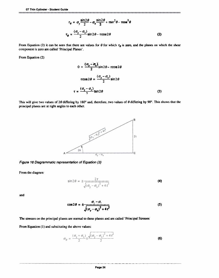
~~tan281'= , (3)
This will give two values of 28 differing by 1800 and, therefore, two values of 8 differing by 9()0. This shows that theprincipal planes are at right angles to each other.
Figure 16 Diagrammatic representation of Equation (3)
From the diagram'
(4)
and
0' -,0'.cas 2 8 = :tJ<~:~i'~ -; (S)
The Sb'eSseS on the principal planes are nonnal to these planes and are called 'Principal Stresses'
From Equation (1) and substituting the above values:
(6)
Page 24
SM1007 Thin Cylinder. Student Guide
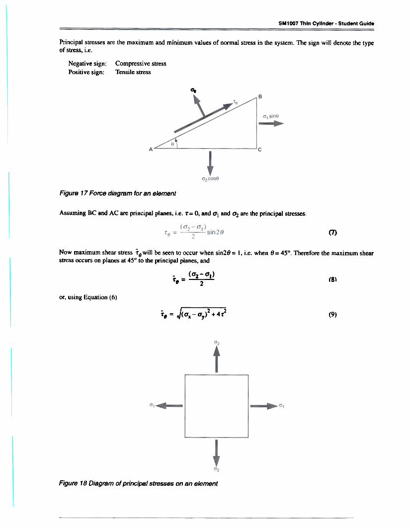
Principal stresses are the maximum and minimum values of normal stress in the system. The sign will denote the typeof stress, i.e.
Negabve sign:Posibve sign:
Compressive stressTensile stress
~
Figure 17 Force diagram for an element
Assuming BC and AC are principal planes, i.e. 'r= O. and 0'1 and ~ are the principal stresses:
(7)
Now maximum shear stress f9will be seen to occur when sin28 = I, i.e. when 8= 45°. Therefore the maximum shearstress occurs on planes at 45° to the principal planes, and
A (aa-a.)-r, = 2 (8)
or, using Equation (6)
A I, - - .2 . _2-r, = ~(ax - ay> +4-r (9)
Figure 18 Diagram of principal stresses on an element

0".£1 = E-
0'2
~=E- E
El and E2 are the values of the principal strains. A negative quantity denotes comp~ve strain while a positive quantitydenotes tensile strain. These strains can be used to construct a Mohr's Strain Circle in the same way as stresses.
Figure 19 Representation of strain on a Mohr's circle
-:--:
Q = Centre of the strain circle
+(~)cao262
=~ + l~)C0828 (12)em
and
En = ~+(~)-(~)C0828
£D = (~ + (Y)COS26

APPENDIX
Nomenclature
MNm-2a Nonnal Stress
MNm-2If Shear Suess
8 Angular Position Degrees
MNm-2Internal PresaureIP(Ratio of &L)Direct Rtlaine
E GNm-2Young's Modulus
v Poisson's Ratio (Ratio of Lateral Strain/Axial Strain)
d Cylinder Internal Diameter m(ormm)
t m (or mm)
I
CyMnder Wall Thk:knes8- - - -Denotes StraIn In the open ends condition
H Denotes !he hoop or circumferential direction
L Denotes the longitudinal direction
Denote particular directionsIxandV