student manual lesson 6- earthwork record system level 1/06 -2009...student manual lesson 6-...
TRANSCRIPT

Student Manual Lesson 6- Earthwork Record System
Version 1.0- 3/09 6-1

Student Manual Lesson 6- Earthwork Record System
6 - 2Version 1.0- 3/09

Student Manual Lesson 6- Earthwork Record System
Materials ManualSection 2.3- Earthwork Record System
2.3.1 PURPOSE
To describe the project Earthwork Records System and to provide a written procedurefor the assembly and use of samefor the assembly and use of same.
6 - 3Version 1.0- 3/09

Student Manual Lesson 6- Earthwork Record System
Materials ManualSection 2.3- Earthwork Record System
2.3.2 SCOPE
This record system is to be used by all inspectors performing density tests on FDOTroadway earthwork construction. Quality control records certified by the Contractor,roadway earthwork construction. Quality control records certified by the Contractor,and Verification records properly maintained for each construction contract, andattested to by responsible District personnel, shall be used by the Department as thebasis for certifying the completed roadway earthwork.
6 - 4Version 1.0- 3/09

Student Manual Lesson 6- Earthwork Record System
Materials ManualSection 2.3- Earthwork Record System
2.3.11 TRAINING
An Earthwork Records System training class is available The training includesAn Earthwork Records System training class is available. The training includesinformation concerning the Earthwork Records System assembly, computer coding togenerate earthwork graphs and the proper use of the completed Earthwork RecordsSystem. Requests for training should be processed through the District ConstructionTraining Administrator. Additional information is available from the State ConstructionTraining Manager. Training information is available at the State Materials Office websiteat:
http://materials.dot.state.fl.us/smo/Geotechnical/Earthwork/earthwork.htm
6 - 5Version 1.0- 3/09

Student Manual Lesson 6- Earthwork Record System
M t i l ManualMaterials ManualSection 2.3- Earthwork Record System
2.3.5 INSTRUCTIONS
Construction contracts with roadway earthwork items shall have an EarthworkRecords System. The Earthwork Records System shall be assembled, available foruse and have all pertinent information entered on each Density Report. Each contractshall have an Earthwork Records System consisting of a Quality Control record withnumbered pages and a separate Verification record. For convenience, a completelyassembled Earthwork Records System may be temporarily separated by roadway,structure, staged construction, multiple numbered projects, or among DensityInspectors. The District Materials Engineer shall approve exceptions. An EarthworkDensity Report shall be used to record all test dataDensity Report shall be used to record all test data.
6 - 6Version 1.0- 3/09

Student Manual Lesson 6- Earthwork Record System
Materials ManualSection 2.3- Earthwork Record System
2.3.6 EARTHWORK RECORDS SYSTEM PREPARATION
Prior to earthwork construction commencing, properly trained Department projectinspection personnel shall be responsible, when necessary, for guiding the Contractorin the Earthwork Records System preparation and organization All Earthwork Recordsin the Earthwork Records System preparation and organization. All Earthwork RecordsSystem graphs shall be computer plotted and page numbered. The Log Book plotprogram, pipe backfill and roadway earthwork computer coding forms, (675-020-05)for Pipe Backfill and (675-020-06) for Embankment, Subgrade, and Base, areavailable from the Department’s Form Library. Embankment graphs are not requiredin areas where no embankment is placed or disturbed. The Pavement Plot sheet maybe added to the record system in these situations. This form is a part of the EarthworkDensity Report form. When electronic design files are available, computer plots for theEarthwork Records System may be prepared utilizing the automated system. Thecomputer-plotted graphs shall accurately illustrate the required testing (the first to thelast lifted placed). Verification plots may be used at the option of the ProjectAdministrator. Any subsequent changes or replots that reflects a change from the plancross sections shall have a detailed note written on appropriate pages.
6 - 7Version 1.0- 3/09

Student Manual Lesson 6- Earthwork Record System
Materials ManualMaterials ManualSection 2.3- Earthwork Record System
2.3.7 Plots
Regular roadway earthwork construction may consist of embankment, subgrade andbase. Attach computer plotted graphs to the Density Report sheets for the sections withE b k L h f h l h ld b h h l i b id ifi dEmbankment. Length of the plots should be such that test locations can be identifiedadequately. For the sections with no Embankment, the Pavement Plot sheet may beused.
Account for all drainage structures and connecting pipe, inside and outside the 1:2 (V:H)slope. Attach plots for all Drainage structures that require testing.
A shorter section roadway graph, less than 500 feet (150 meters), may be used to plotsections of MSE wall construction.
Use a different bar chart for each earthwork pavement layer compacted separately.
6 - 8Version 1.0- 3/09

Student Manual Lesson 6- Earthwork Record System
Materials ManualMaterials ManualSection 2.3- Earthwork Record System
2.3.8 EXCAVATION OF UNSUITABLE MATERIALS
All computer-plotted embankment graphs shall be corrected for excavation of unsuitablematerials. The anticipated depth of excavation may be coded as an undercut depth,(Form 675 020 06 Embankment Subgrade and Base) to provide a blank space for(Form 675-020-06, Embankment, Subgrade and Base), to provide a blank space forhand corrections. If the graph is re-plotted, make an appropriate note to identifydeviation from the plans.
6-9Version 1.0- 3/09

Student Manual Lesson 6- Earthwork Record System
6 - 10Version 1.0- 3/09

Student Manual Lesson 6- Earthwork Record System
6-11Version 1.0- 3/09

Student Manual Lesson 6- Earthwork Record System
6 - 12Version 1.0- 3/09

Student Manual Lesson 6- Earthwork Record System
6-13Version 1.0- 3/09

Student Manual Lesson 6- Earthwork Record System
Notes:Notes:
A) A separate line must be completed for each gauge used on the project.
B) If a gauge is calibrated or repaired during construction, comply with specification 120-10.1.1 and enter information above.
C) Enter Inspectors initials and TIN each time equipment is
compared.
D) Include and retain a copy of gauge calibration parameters.
6-14Version 1.0- 3/09

Student Manual Lesson 6- Earthwork Record System
1. Financial Number: Enter the Project FIN #1. Financial Number: Enter the Project FIN #
2. Gauge Serial #: Enter the manufacturer's serial number for the nuclear moisture/density gauge.
3. Calibration Date: Enter the most recent gauge calibration date.
4. Dry Density: Enter the computed Dry Density
5. QC / VT / IA: QC / VT / IA: Enter the inspector type (QC / VT / IA) and inspector level (ECI 1 and/or 2).6. Initial Equipment Date: Enter the date the initial equipment check was performed.7. Initials: Enter the initials of the inspector just as they will appear in the Density Log Sheets.
8. TIN #: Enter the inspector's CTQP training identification number.9. Date Begun: Enter the date the inspector begins testing with the gauge listed or the date the ga ge is recei ed back follo ing recalibration or repairsdate the gauge is received back following recalibration or repairs.10. Date Ended: Enter the date the inspector completes testing with the gauge listed or the date the gauge is sent for recalibration or repairs.
6-15Version 1.0- 3/09

Student Manual Lesson 6- Earthwork Record System
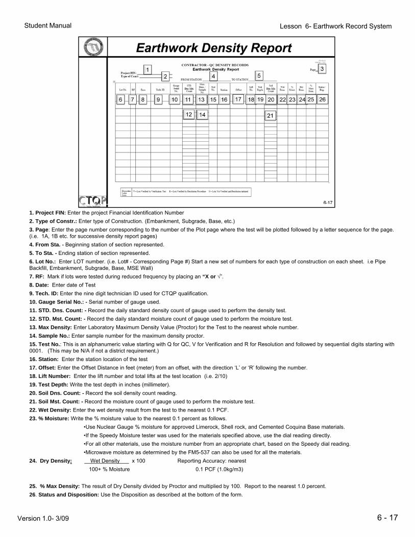
General Notes & Instructions: Earthwork Density Report
All required information on the Density Report shall be current, legible and written inink. No transcribed, rewritten, or otherwise copied Record Sheets shall be allowed orincluded. Dittos, arrows, white-out, and erasures shall be avoided. A correction shallbe indicated with a single line striking through the original data and the corrected datawritten close to it. All corrections or other notes made on the plot or Record pages shallbe initialed. Special Provisions or other issues effecting earthwork testing andsampling should be noted on the LOT INDEX PAGES. Retain a copy of the CalibrationParameter sheet in the Earthwork Record System for any gauge used on the project.Add a new Calibration Parameter sheet each time a Nuclear Gauge is recalibrated.
Lifts, Lots or partial lots affected by water and consequently not tested shall beidentified on the DENSITY RECORD AND LOT INDEX sheets. Example: “Lifts 1-3affected by water.”
6 - 16Version 1.0- 3/09
Student Manual Lesson 6- Earthwork Record System
1. Project FIN: Enter the project Financial Identification Number
2. Type of Constr.: Enter type of Construction. (Embankment, Subgrade, Base, etc.)
3. Page: Enter the page number corresponding to the number of the Plot page where the test will be plotted followed by a letter sequence for the page. (i.e. 1A, 1B etc. for successive density report pages)
4. From Sta. - Beginning station of section represented.
5. To Sta. - Ending station of section represented.
6. Lot No.: Enter LOT number. (i.e. Lot# - Corresponding Page #) Start a new set of numbers for each type of construction on each sheet. i.e Pipe Backfill Embankment Subgrade Base MSE Wall)Backfill, Embankment, Subgrade, Base, MSE Wall)
7. RF: Mark if lots were tested during reduced frequency by placing an “X or √”.
8. Date: Enter date of Test
9. Tech. ID: Enter the nine digit technician ID used for CTQP qualification.
10. Gauge Serial No.: - Serial number of gauge used.
11. STD. Dns. Count: - Record the daily standard density count of gauge used to perform the density test.
12. STD. Mst. Count: - Record the daily standard moisture count of gauge used to perform the moisture test.
13. Max Density: Enter Laboratory Maximum Density Value (Proctor) for the Test to the nearest whole number.
14. Sample No.: Enter sample number for the maximum density proctor.
15. Test No.: This is an alphanumeric value starting with Q for QC, V for Verification and R for Resolution and followed by sequential digits starting with 0001. (This may be N/A if not a district requirement.)
16. Station: Enter the station location of the test
17. Offset: Enter the Offset Distance in feet (meter) from an offset, with the direction ‘L’ or ‘R’ following the number.
18. Lift Number: Enter the lift number and total lifts at the test location (i.e. 2/10)
19. Test Depth: Write the test depth in inches (millimeter).
20. Soil Dns. Count: - Record the soil density count reading.
21. Soil Mst. Count: - Record the moisture count of gauge used to perform the moisture test.
22. Wet Density: Enter the wet density result from the test to the nearest 0.1 PCF.
23. % Moisture: Write the % moisture value to the nearest 0.1 percent as follows.
•Use Nuclear Gauge % moisture for approved Limerock, Shell rock, and Cemented Coquina Base materials.
•If the Speedy Moisture tester was used for the materials specified above, use the dial reading directly.
•For all other materials, use the moisture number from an appropriate chart, based on the Speedy dial reading.
•Microwave moisture as determined by the FM5-537 can also be used for all the materials.
24 Dry Density: Wet Density x 100 Reporting Accuracy: nearest
6 - 17
24. Dry Density: Wet Density x 100 Reporting Accuracy: nearest
100+ % Moisture 0.1 PCF (1.0kg/m3)
25. % Max Density: The result of Dry Density divided by Proctor and multiplied by 100. Report to the nearest 1.0 percent.
26. Status and Disposition: Use the Disposition as described at the bottom of the form.
Version 1.0- 3/09

Student Manual Lesson 6- Earthwork Record System
1. Project FIN: Enter the project Financial Identification Number.
2. Page: Enter the corresponding page number.2. Page: Enter the corresponding page number.
3. Sample Number: Enter the SIX character sample number i.e. 00001Q
The “Q” at the end indicates the sample was collected and tested by Quality Control Personnel
Sample numbers ending in “V or R” will be used for samples collected and tested by VT or RT Personnel
All samples should be recorded in the order they were obtained.
Verification, Resolution, and Independent Verification sample numbers should match the corresponding QC sample no.
Example: QC sample “00002Q” should be verified by Verification Sample “00002V” or resolved by Resolution Sample “00002R”.00002R .
When preparing Sample Transmittal Cards for V samples and R samples, note the “Q” sample number that the V or R should be compared to and also list any “Q” sample numbers that will be verified if comparison is favorable.
Example for “V” sample: Compares to 00002Q. Also verifies 00001Q, 00003Q, and 00004Q.
NOTE: THE RESULTS OF ALL “Q” SAMPLES MUST BE VERIFIED OR RESOLVED AS REQUIRED BY SPECIFICATION.
4. Material Description: Enter a description of material being sampled. p p g p
5. Max Density: Enter Laboratory Maximum Density Value (Proctor) for the sample.
6. Opt Moist: Enter Laboratory Optimum Moisture Value for the sample.
7. Type of Constr: Indicate the expected use of the material. i.e. , limerock base, pipe backfill etc. Skip sufficient lines to readily separate the material types OR use separate sheets for each Material number.
8. Lots Represented: Indicate the corresponding LOT numbers or project limits (for Embankment samples) represented by the Proctor results.
9. Sample Number: Enter the corresponding Verification sample number i.e. 00001V
6-18
10. Max Density: Enter the corresponding Verification Maximum Density Value (Proctor).
Version 1.0- 3/09

Student Manual Lesson 6- Earthwork Record System
1. Project FIN: Enter the project Financial Identification Number.
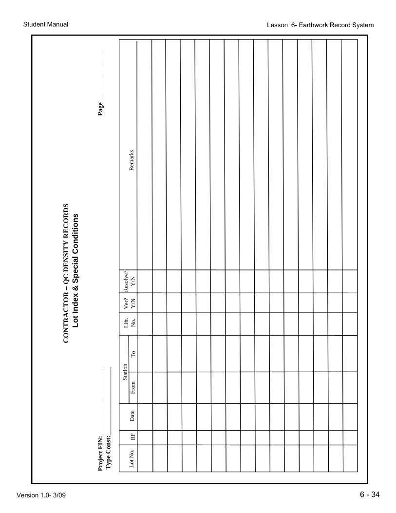
2. Type of Const: Enter applicable Type of Construction if the LOTS are indexed (Numbered) by material number. If LOTS are indexed consecutively for the entire project enter “N/A” at the top and indicate the type of construction in REMARKS. (Pipe backfill, embankment, RE wall, baserock, etc.)
3. Page: Enter appropriate page number – All pages must be numbered
4. Lot No.: Enter LOT No. Each LOT must be verified as specified in the Specifications. p pIf not, it must be resolved as specified in the Specifications.
5. RF: Indicate if lots were tested during reduced frequency by placing an “X or √”.
6. Rdwy: Enter “L” for Left, “R” for Right, or “C” for Composite to identify the general LOT location
7. Station No. From: Enter beginning station of Lot.
8 St ti N T E t di t ti f L t8. Station No. To: Enter ending station of Lot.
9. Lift No.: Enter the lift number /total lifts (i.e. 1/10) at the LOT location – NOTE: If thick lift operations are used, indicate the Standard 6-inch lift numbers (i.e. 5-6/10)
10. Ver?: Enter “Y” if the QC test for this LOT was verified. Enter “N” if the QC test for this LOT was not verified and Resolution Test was required
11. Resolved?: If LOT not verified, enter Y if resolved; N if not resolved.
6 - 19
12. Remarks: Remarks column is used to record any special conditions, comments or other information needed to explain or clarify project issues or conditions. Use this section to note Material type (if applicable), LOTS affected by water, thick lift operations, reduced frequency testing, use of flowable fill, etc.
Version 1.0- 3/09

Student Manual Lesson 6- Earthwork Record System
6-20Version 1.0- 3/09

Student Manual Lesson 6- Earthwork Record System
6 - 21Version 1.0- 3/09

Student Manual Lesson 6- Earthwork Record System
6-22Version 1.0- 3/09

Student Manual Lesson 6- Earthwork Record System
Notes:Notes:
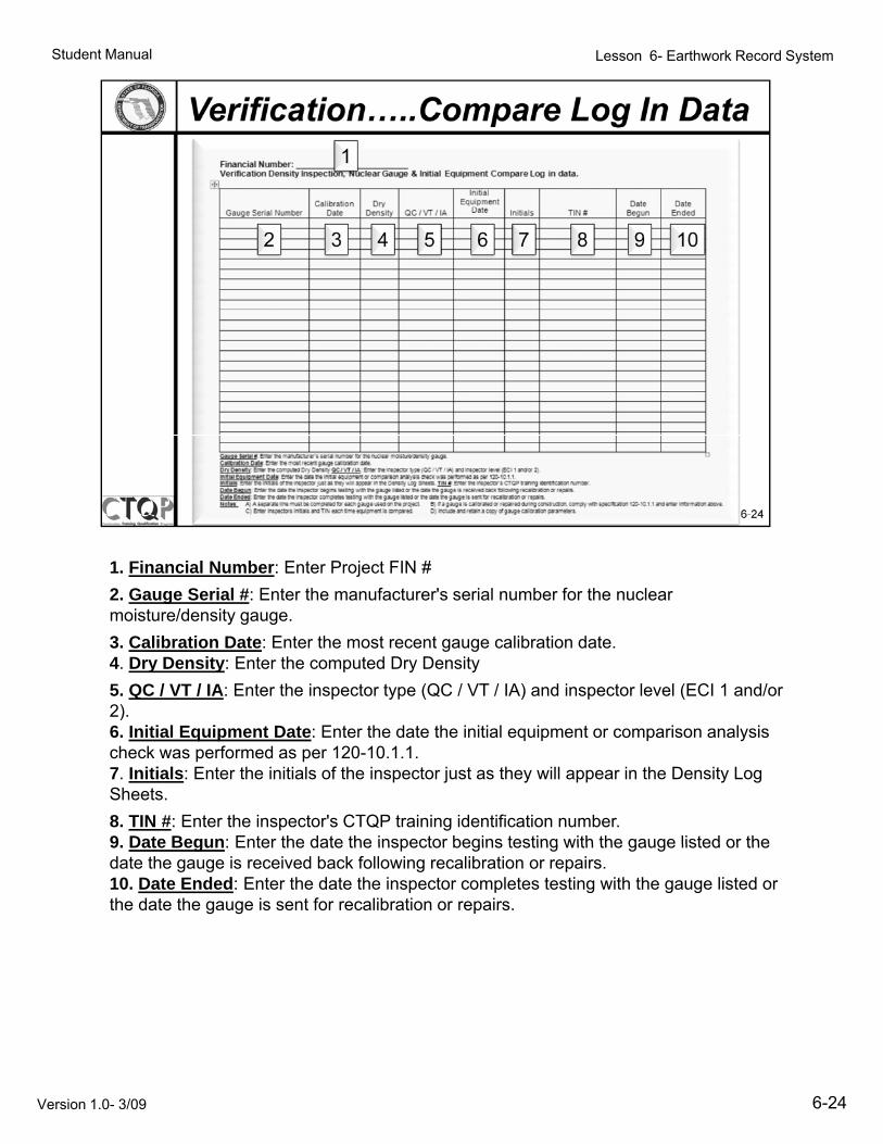
A) A separate line must be completed for each gauge used on the project.
B) If a gauge is calibrated or repaired during construction, comply with specification 120-10.1.1 and enter information above.
C) Enter Inspectors initials and TIN each time equipment is compared.
D) Include and retain a copy of gauge calibration parameters.
6-23Version 1.0- 3/09
Student Manual Lesson 6- Earthwork Record System
1. Financial Number: Enter Project FIN #1. Financial Number: Enter Project FIN #
2. Gauge Serial #: Enter the manufacturer's serial number for the nuclear moisture/density gauge.
3. Calibration Date: Enter the most recent gauge calibration date.4. Dry Density: Enter the computed Dry Density
5. QC / VT / IA: Enter the inspector type (QC / VT / IA) and inspector level (ECI 1 and/or 2)2).6. Initial Equipment Date: Enter the date the initial equipment or comparison analysis check was performed as per 120-10.1.1.7. Initials: Enter the initials of the inspector just as they will appear in the Density Log Sheets.
8. TIN #: Enter the inspector's CTQP training identification number.9 Date Begun: Enter the date the inspector begins testing with the gauge listed or the9. Date Begun: Enter the date the inspector begins testing with the gauge listed or the date the gauge is received back following recalibration or repairs.10. Date Ended: Enter the date the inspector completes testing with the gauge listed or the date the gauge is sent for recalibration or repairs.
6-24Version 1.0- 3/09

Student Manual Lesson 6- Earthwork Record System
General Notes & Instructions: Verification Density Report
All required information on the Density Report shall be current, legible and written in ink.No transcribed, rewritten, or otherwise copied Record Sheets shall be allowed orincluded. Dittos, arrows, white-out, and erasures shall be avoided. A correction shall beindicated with a single line striking through the original data and the corrected datawritten close to it. All corrections or other notes made on the plot or Record pages shallbe initialed. Special Provisions or other issues effecting earthwork testing and samplingshould be noted. Retain a copy of the Calibration Parameter sheet in the EarthworkRecord System for any verification gauge used on the project. Add a new CalibrationParameter sheet each time a Nuclear Gauge is recalibrated.
6 - 25Version 1.0- 3/09

Student Manual Lesson 6- Earthwork Record System
1. Project FIN: Enter the project Financial Identification Number
2. Type of Const.: Enter type of Construction. (Embankment, Subgrade, Base, etc.)
3. Page: Enter the page number corresponding to the number of the Plot page where the test will be plotted followed by an Alphabetic letter sequence for the page. (i.e. 1A, 1B etc. for successive density report pages)
4. From Sta. - Beginning station of Lot represented.
5. To Sta. - Ending station of Lot represented. * Get approval from the District Materials Earthwork Coordinator to write in “From Station” and “To Station” for the purpose of recording verification for multiple QC sheets on one pagefor the purpose of recording verification for multiple QC sheets on one page.
6. Lot number: Enter the Lot number using the following format (QC Lot# - Corresponding QC Page #)
7. Date: Enter date of Test
8. Tech. ID: Enter the nine digit technician ID used for CTQP qualification.
9. Gauge Serial No.: - Serial number of gauge used.
10. STD. Dns. Count: - Record the daily standard density count of gauge used to perform the density test.
11. STD. Mst. Count: - Record the daily standard moisture count of gauge used to perform the moisture test.
12. Max Density: Enter Laboratory Maximum Density Value (Proctor) for the Test to the nearest whole number.
13. Sample No.: Enter sample number for the maximum density proctor.
14. Test No.: This is an alphanumeric value starting with Q for QC, V for Verification and R for Resolution and followed by sequential digits
starting with 0001. (Test No. may not be applicable in all districts.)
15, Station: Enter the station location of the test
16. Offset: Enter the Offset Distance in feet (meter) from an offset, with the direction ‘L’ or ‘R’ following the number.
17. Lift Number: Enter the lift number and total lifts at the test location (i.e. 2/10)
18. Test Depth: Write the test depth in inches (millimeter).
19 Soil Dns Count: - Record the soil density count reading19. Soil Dns. Count: - Record the soil density count reading.
20. Soil Mst. Count: - Record the moisture count of gauge used to perform the moisture test.
21. Wet Density: Enter the wet density result from the test to the nearest 0.1 PCF.
22. % Moisture: Write the % moisture value to the nearest 0.1 percent as follows.
•Use Nuclear Gauge % moisture for approved Limerock, Shell rock, and Cemented Coquina Base materials.
•If the Speedy Moisture tester was used for the materials specified above, use the dial reading directly.
•For all other materials, use the moisture number from an appropriate chart, based on the Speedy dial reading.
•Microwave moisture as determined by the FM5-537 can also be used for all the materials.
6 - 26
23. Dry Density: Wet Density x 100 Reporting Accuracy: nearest
100+ % Moisture 0.1 PCF (1.0kg/m3)
24. % Max Density: The result of Dry Density divided by Proctor and multiplied by 100. Report to the nearest 1.0 percent.
25. Lots Verified: List lots verified by this test. (QC Lot#s - Corresponding QC Page #s)
.
Version 1.0- 3/09

Student Manual Lesson 6- Earthwork Record System
1. Project FIN: Enter the project Financial Identification Number. j p j
2. Page: Enter the corresponding page number.
3. Sample Number: Enter the Five character QC sample number i.e. 00001Q
4. Material Description: Enter a description of material being sampled.
5. QC Max Density: Enter Laboratory Maximum Density Value (Proctor) for the sample.
6. QC Opt Moist: Enter Laboratory Optimum Moisture Value for the sample.
7. Type of Constr.: Enter the type of Construction. Use ‘L’ or ‘R’ to specify Left or Right roadway and/or side.
8. Lots Represented: Indicate the corresponding lot numbers represented by the Proctor results.
9 Sample Number: Enter the corresponding Verification sample number i e9. Sample Number: Enter the corresponding Verification sample number i.e. 00001V. (Make sure numbers match)
10. Max Density: Enter the corresponding Verification Maximum Density Value (Proctor).
6-27Version 1.0- 3/09

Student Manual Lesson 6- Earthwork Record System
This is a typical Graph Plot sheet produced by the Departments Plot Program for an E b k t S tiEmbankment Section.
The scale, both Stationing and Elevation, will vary depending upon the data input into the program.
Note that the solid line on the graph represents the “Top of Embankment”. This is notthe Top of Roadway.
Al t th U P d t th t f th h h t Th f it hAlso note the User Pads at the top of the graph sheet. These are for items, such as Base, Subgrade, etc., that are a constant thickness throughout the project. Densities in these areas are plotted in these User pads.
6 - 28Version 1.0- 3/09

Student Manual Lesson 6- Earthwork Record System
Remember – Lifts are counted starting from the bottom of the deepest excavation or g pgreatest embankment fill section.
And if you want, the lifts can be labeled off to the side for convenience.
6 - 29Version 1.0- 3/09

Student Manual Lesson 6- Earthwork Record System
6 - 30Version 1.0- 3/09

Student Manual Lesson 6- Earthwork Record System
EXERCISE
You work for ABC Construction and have been assigned as the QC Density Inspectoron SR 001 (FIN #123456789), left roadway. The serial number of your nuclear gaugeis 12345 and was last calibrated 01/01/09. On April 10, 2009, you participated in theInitial Equipment Comparison testing, recording a Dry Density of 118.6 pcf. On April15, 2009, you arrive on site with your gauge (Serial # 12345) to begin QC Testing.Your daily standard counts for density is 2660 and for moisture is 666. From they ygauge diary you find the last four standard counts for each and determine the gaugeis within tolerance for Standard Counts.
Your company is placing embankment in 6 inch compacted lifts utilizing a gray sandwith traces of limerock. The first three lifts are affected by water and you are unable totest them. Your first test (Q0001) will be at Station 1222+05, 15 ft. Left of C/L ofConstruction on LOT 4 (lift 4). During the test, your gauge indicates a Soil DensityCount of 2100 and a Moisture Count of 600, with a Wet Density of 121.2 pcf and yourSpeedy Moisture test result was 10.1%, which converts to 11.2%.
The Verification Technician shows up to do the Verification Test for the LOTs inquestion and is using a gauge from the same manufacturer. Verification’s testindicates a Wet Density is 120.6 pcf and a converted Moisture of 10.6%.
Based upon the above information and the following 5 QC forms complete the QC
6 - 31
Based upon the above information and the following 5 QC forms, complete the QCDensity Inspection, Nuclear Gauge & Initial Equipment Compare Log In Data sheet,QC Earthwork Density Record , the LOT Index and plot the test on the density loggraph.
Version 1.0- 3/09

Student Manual Lesson 6- Earthwork Record System
Dat
eE
nd
ed
rmat
ion
abov
e.
n d
ata
Dat
eB
egu
n
tion
120
-10.
1.1
and
ente
r in
fo
Com
par
e L
og in
sT
IN #
gaug
e ca
libr
atio
n da
te.
2).
iden
tifi
cati
on n
umbe
r.on
or
repa
irs.
ucti
on, c
ompl
y w
ith
spec
ific
atn
para
met
ers.
al E
qu
ipm
ent
C
Init
ial
qu
ipm
ent
Dat
eIn
itia
l s
n D
ate:
Ent
er th
e m
ost
rece
nt
insp
ecto
r le
vel (
EC
I 1
and/
or
the
insp
ecto
r's C
TQ
P tr
aini
ng
ved
back
fol
low
ing
reca
libr
atio
nt f
or r
ecal
ibra
tion
or
repa
irs.
ated
or
repa
ired
dur
ing
cons
tru
ain
a co
py o
f ga
uge
cali
brat
ion
Gau
ge &
In
itia
QC
/VT
/IA
Eq
ure/
dens
ity
gaug
e. C
alib
rati
onec
tor
type
(Q
C /
VT
/ IA
) an
d or
med
.it
y L
og S
heet
s. T
IN #
: Ent
er t
or th
e da
te th
e ga
uge
is r
ecei
vte
d or
the
date
the
gaug
e is
sen
ect.
B)
If a
gau
ge is
cal
ibra
d.
D)
Incl
ude
and
reta
____
____
____
ecti
on, N
ucl
ear
bra
tion
Dat
eD
ryD
ensi
ty
rol D
ensi
ty I
nspe
ctor
)nu
mbe
r fo
r th
e nu
clea
r m
oist
uQ
C /
VT
/ IA
:E
nter
the
insp
eia
l equ
ipm
ent c
heck
was
per
fos
they
wil
l app
ear
in th
e D
ensi
test
ing
wit
h th
e ga
uge
list
ed o
etes
test
ing
wit
h th
e ga
uge
list
or e
ach
gaug
e us
ed o
n th
e pr
oje
ch ti
me
equi
pmen
t is
com
pare
d
ber
:___
____
___
l Den
sity
In
spe
l Nu
mb
erC
alib D
be c
ompl
eted
by
Qua
lity
Con
trnt
er th
e m
anuf
actu
rer's
ser
ial n
er th
e co
mpu
ted
Dry
Den
sity
Qt
Dat
e: E
nter
the
date
the
init
iin
itia
ls o
f th
e in
spec
tor
just
as
r th
e da
te th
e in
spec
tor
begi
nsr
the
date
the
insp
ecto
r co
mpl
era
te li
ne m
ust
be c
ompl
eted
fo
Insp
ecto
rs in
itia
ls a
nd T
IN e
ac
6 - 32Version 1.0- 3/09
Fin
anci
al N
um
bQ
ual
ity
Con
tro
Gau
ge S
eria
l
Inst
ruct
ion
s: (
to b
Gau
ge S
eria
l #: E
nD
ry D
ensi
ty: E
nte
Init
ial E
qu
ipm
ent
Init
ials
: Ent
er th
e D
ate
Beg
un
: Ent
erD
ate
En
ded
: E
nter
Not
es:
A)
A s
epar
C)
Ent
er I

Student Manual Lesson 6- Earthwork Record System
Pag
e___
____
% M
ax.
Den
s.
Sta
tus/
Dis
p.et
Den
s.
%M
oist
.D
ryD
ens.
% D
N__
____
____
____
__
t No.
Tes
tD
epth
Soi
lD
ns./M
st.
Cou
ntW
e
esol
utio
n in
itia
ted
NS
ITY
RE
CO
RD
Sit
y R
epo
rt
____
__T
O S
TA
TIO
N
atio
nO
ffse
tL
ift
N
-L
ots
Not
Ver
ifie
d an
d R
e
RA
CT
OR
–Q
C D
EN
Ear
thw
ork
Den
si
TA
TIO
N__
____
____
__
.M
ax.
Den
s./
Sam
ple
No. T
est N
o.St
a
by R
esol
utio
n P
roce
dure
CO
NT
R
FR
OM
ST
____
____
Gau
geS
eria
l No.
STD
Dns
./Mst
Cou
nt
on T
est
R-
Lot
s V
erif
ied
N:_
____
____
____
____
_st
:___
____
____
____
___
Dat
eT
ech
ID.
V-
Lot
s V
erif
ied
by V
erif
icat
io
6-33Version 1.0- 3/09
Pro
ject
FIN
Typ
e C
ons
Lot
No.
RF
VD
ispo
siti
onL
ette
rC
ode
Student Manual Lesson 6- Earthwork Record System
____
___
Pag
e___
____
___
Rem
arks
SIT
Y R
EC
OR
DS
Co
nd
itio
ns
RA
CT
OR
–Q
C D
EN
St
Ind
ex &
Sp
ecia
l
Ver
?Y
/NR
esol
ve?
Y/N
CO
NT
RL
ot
____
____
Stat
ion
Lif
t.N
o.T
o
N:_
____
____
____
____
_st
:___
____
____
____
___
RF
Dat
eS
Fro
m
6 - 34Version 1.0- 3/09
Pro
ject
FIN
Typ
e C
ons
Lot
No.
R

Student Manual Lesson 6- Earthwork Record System
11
10
10 15
06
11
10
10 15
06
0
00
01
V
11
0
00
02V
11
0
00
03V
11
0
00
04
V
11
0
00
05
V
10
1
0
00
01
V
11
0
00
02V
11
0
00
03V
11
0
00
04
V
11
0
00
05
V
10
1
mb
.
1
mb
.
2
-3
mb
.
4
-6
mb
.
7
mb
.
8
mb
.
1
mb
.
2
-3
mb
.
4
-6
mb
.
7
mb
.
8
1
0
Em
b
1
1
Em
1
0
Em
9
Em
9
Em
1
0
Em
b
1
1
Em
1
0
Em
9
Em
9
Em
11
2
11
3
on
e1
08
11
2
Of
cla
y1
08
11
2
11
3
ock
10
8
11
2
Of
cla
y1
08
n s
an
d
w/
tro
f li
mes
to
n s
an
d w
/ ro
ots
wn
sa
nd
w/
tr.
O
n s
an
d
w/
tro
f li
mer
o
n s
an
d w
/ ro
ots
wn
sa
nd
w/
tr.
O
1Q
G
ray
san
d
2Q
Ta
n &
bro
wn
3Q
G
ray
san
d w
4Q
G
ray
bro
wn
05
Q Ta
n &
bro
w
1234
5678
9
1Q
G
ray
san
d
2Q
Ta
n &
bro
wn
3Q
G
ray
san
d w
4Q
G
ray
bro
wn
05
Q Ta
n &
bro
w
1234
5678
9
6 - 35Version 1.0- 3/09
00
001
00
002
00
003
00
004
00
00
00
001
00
002
00
003
00
004
00
00

Student Manual Lesson 6- Earthwork Record System
x122.
00
123.
00
124.
00
125.
00
126.
00
127.
00
128.
00
129.
00
130.
00
131.
00
132.
00
133.
00
121.
00
DL
BPL
OT
Ver
x.x.
x
1225
+00
Ver
ifie
d by
____
____
__
1224
+00
Pla
n E
leva
tion
s V
1223
+00
2345
6789
men
t-no
n S
IA
DW
AY
Sta
tion
(F
T)
1222
+00
FD
OT
Pro
ject
1D
ensi
ty-
Em
bank
mS
R 0
01, L
EF
T R
OA
1221
+00
+00
Feb-05 6 - 36
BASE
1.
000
SUBG
1.
000
Ele
vati
on (
FT
)1220
+12
1.00
122.
00
123.
00
124.
00
125.
00
126.
00
127.
00
128.
00
129.
00
130.
00
131.
00
132.
00
133.
00

Student Manual Lesson 6- Earthwork Record System
EXERCISEEXERCISE
You are responsible for Verification Testing on SR 001(FIN #123456789), left roadway.Your assigned nuclear gauge is serial number 111938 and was last calibrated11/01/08. On April 10, 2009, you participated in the Initial Equipment Comparisontesting, recording a Dry Density of 117.9 pcf. On April 15, 2009, you arrive on site withyour gauge (Serial #111938) to begin Verification Testing. Today’s standard counts are2734 for density and 644 for moisture From the gauge diary you find the last four2734 for density and 644 for moisture. From the gauge diary you find the last fourstandard counts for each and determine the gauge is within tolerance for StandardCounts.
The contractor has placed 4 consecutive LOTs (LOTs 5-8) of tan and brown fine sandwith traces of clay and all have passed required QC Density testing. Your randomVerification test location for Test. No. V0002 is determined to be LOT 8 (Lift 8 of 13),Station 1224+75 at 6 ft. left of C/L of Construction. During the test, your gaugeStation 1224 75 at 6 ft. left of C/L of Construction. During the test, your gaugeindicates a Soil Density Count of 2068 and a Moisture Count of 616. Your nucleardensity test result for Wet Density is 123.8 pcf and Speedy Moisture test is 13.0%,which convert to 14.9%. The Proctors had compared and so you are using the QCProctor of 108 pcf.
Based upon the above information and the following 3 QC forms, complete theVerification Density Inspection, Nuclear Gauge & Initial Equipment Compare Log In
6 - 37
y p , g q p p gData sheet, and Verification Earthwork Density Record.
Version 1.0- 3/09

Student Manual Lesson 6- Earthwork Record System
Dat
eE
nd
ed
form
atio
n ab
ove.
dat
a
Dat
eB
egu
n
cati
on 1
20-1
0.1.
1 an
d en
ter
in
omp
are
Log
in d
als
TIN
#
or 2
).
ng id
enti
fica
tion
num
ber.
tion
or
repa
irs.
rs.
stru
ctio
n, c
ompl
y w
ith
spec
ific
ion
para
met
ers.
Eq
uip
men
t C
o
Init
ial
Eq
uip
men
tD
ate
Init
ia
nd in
spec
tor
leve
l (E
CI
1 an
d/o
r th
e in
spec
tor's
CT
QP
trai
nin
eive
d ba
ck f
ollo
win
g re
cali
brat
sent
for
rec
alib
rati
on o
r re
pair
brat
ed o
r re
pair
ed d
urin
g co
nset
ain
a co
py o
f ga
uge
cali
brat
i
Gau
ge &
In
itia
l
QC
/VT
/IA
E
stur
e/de
nsit
y ga
uge.
spec
tor
type
(Q
C /
VT
/ IA
) an
rfor
med
.ns
ity
Log
She
ets.
TIN
#: E
nter
d or
the
date
the
gaug
e is
rec
eli
sted
or
the
date
the
gaug
e is
soj
ect.
B)
If a
gau
ge is
cal
ibre
d.
D)
Incl
ude
and
r
____
____
____
_ti
on, N
ucl
ear
G
ibra
tion
Dat
eD
ryD
ensi
ty
al n
umbe
r fo
r th
e nu
clea
r m
ois
e ca
libr
atio
n da
te.
y Q
C /
VT
/ IA
:E
nter
the
ins
niti
al e
quip
men
t che
ck w
as p
eras
they
wil
l app
ear
in th
e D
enns
test
ing
wit
h th
e ga
uge
list
em
plet
es te
stin
g w
ith
the
gaug
e l
for
each
gau
ge u
sed
on th
e pr
oea
ch ti
me
equi
pmen
t is
com
par
um
ber
:___
____
Den
sity
In
spec
t
ial N
um
ber
Cal
i D
Ent
er th
e m
anuf
actu
rer's
ser
iate
: Ent
er th
e m
ost
rece
nt g
aug
nter
the
com
pute
d D
ry D
ensi
tyen
t D
ate:
Ent
er th
e da
te th
e in
he in
itia
ls o
f th
e in
spec
tor
just
te
r th
e da
te th
e in
spec
tor
begi
nnt
er th
e da
te th
e in
spec
tor
com
ppa
rate
line
mus
t be
com
plet
ed
r In
spec
tors
init
ials
and
TIN
e
6 - 38Version 1.0- 3/09
Fin
anci
al N
uV
erif
icat
ion
Gau
ge S
eri
Gau
ge S
eria
l #:
Cal
ibra
tion
Dat
Dry
Den
sity
: En
Init
ial E
qu
ipm
eIn
itia
ls: E
nter
thD
ate
Beg
un
: En
Dat
e E
nd
ed:
En
Not
es:
A)
A s
epC
) E
nter

Student Manual Lesson 6- Earthwork Record System
Pag
e___
____
% Max
.D
ens.
Lot
sA
ccep
ted
Wet
D
ens.
%M
oist
.D
ryD
ens.
Rep
ort
ift
No.
Tes
tD
epth
Soi
lD
ns./M
st.
Cou
ntW D
wo
rk D
ensi
ty R
atio
nO
ffse
tL
i N
cati
on
-E
arth
w
____
____
____
__
t.M
ax.
Den
s./
Sam
ple
No.
Tes
tN
o.St
a
Ver
ific
___
TO
ST
AT
ION
___
____
____
Gau
geS
eria
l No.
STD
Dns
./Ms t
Cou
nt
TIO
N__
____
____
____
_
N:_
____
____
____
____
_st
:___
____
____
____
___
Dat
eT
ech
ID.
6 - 39Version 1.0- 3/09
FR
OM
ST
AT
Pro
ject
FIN
Typ
e C
ons
Lot
No.
D

Student Manual Lesson 6- Earthwork Record System
6 - 40Version 1.0- 3/09

Student Manual Lesson 6- Earthwork Record System
6 - 41Version 1.0- 3/09

Student Manual Lesson 6- Earthwork Record System
NOTES
6 - 42Version 1.0- 3/09