structure simulation and blade design of an · pdf filestructure simulation and blade design...
TRANSCRIPT

1
STRUCTURE SIMULATION AND BLADE DESIGNOF AN AIRCRAFT ENGINE
André OLLIVIERSNECMA site of Villaroche
77550 Moissy-cramayel, France
ABSTRACT
Structural analysis have progressed at a level such that they are now increasingly used all daysin activities of mechanical engineering
In 25 years at SNECMA, analyses have for main objective to provide in both detail andoverall a knowledge of the behaviour and damage of the part, they are an help with thedecision in design conception via optimization.
We are currently in a period of utilization of more and more simulations , what allows toreduce significantly the number of tests. Researches allow to develop tools simulating thebehavior increasingly precisely.
These simulations have become of necessary tools, to reduce costs , to reduce cycles, todesign robust. Take into account very early manufacture constraints in simulations,improved the simultaneous engineering.
It is demonstrated here after that the large use of simulation during the period of life of theproduct, will allow to improve them, and to answer as quickly as possible to quality andreliability needs of the companies.
Finally, it is necessary to insist on the inter-operability of tools of simulation, centered on anumerical geometrical model. This inter - operability has to accompany the concept ofextended enterprise and the world cooperation necessity. These are the keys of the successof industrial products design for the next century

2
INTRODUCTION
Structural analysis are progressing since several decades. They have progressively allowed tosimulate various types of life situation, in the same time its utilization has become more userfriendly. A great part of this progress is du to dramatic improvement of capacities ofcomputing hardware performance. The time to perform analyses has decreased very strongly,in the same time size and the complexity of models have increased. Software have progressedto allow engineer to visualize problems very complex.
SNECMA uses since near 25 years, finite elements tools to design engine parts. However,these analyses were, in general employed to help to the comprehension of the behavior of thestructure, and to provide elements participating to choice the optimum design. An importantpart of the design qualification was based on very numerous tests. These tests are used tovalidate decisions, and to demonstrate that design met the specifications. It has become rapidlyevident that we could reduce very significantly the number of tests, therefore the costsassociated, if it was possible to perform appropriate simulations. The level has to be such thatthe simulation brings a level of confidence equal to a test.
The competition on the civil aeronautic market, has obliged all actors to conduct actions toreduce by more than 2 the design cycle. The simulation is a fundamental tool that allows toreach this goal. Structural simulation is “virtual”, so all actors can see virtually all the designerand manufacturer views of the part, all the life situations without spending no more than“paper “ and computer time. Manufacturer can earlier decide to launch tools because theyhave a improved risks visibility.
Satisfaction of the client needs to increase more an more the quality of the engines. Thesimulation is an essential answer, because it allows, especially to guarantee the robustness.The competition is severe, markets will be won by offering clients, systems “on shelves”,therefore it will be necessary to be able flexibility in conception. The extended simulation,associated with technologies on “shelves” is the right answer. We show here after todaysimulations, and future developments. In this paper ,the simulations are illustrated on a partwitch is in the heart of the engines : The BLADE [Fig.2].

3
Structural analysis today
The analysis by finite elements are largely used. The goal of these analyses is to determine,especially on blades, a distribution of constraints coming from aerodynamic pressure loads,centrifugal effects, and heterogeneous temperature fields that vary during the aircraft mission.They are also used to predict modes and frequencies of vibration [Fig 3]. These analysis aremade to demonstrate the structural integrity of the blade. Mainly, for the dynamicscalculations, results are compared to experience and provide an help to the decision [Fig 4].
Thus the design and analysis with theoretical tools are possible. However the confidence thatwe can have in a theoretical model to represent the real structure varies greatly, it depends onquality of tests available, and the level of novelty compare to the experience. An other viewof the simulation is its utilization during early project stage, concept, detail, manufacturestages, and in use stage. Process has been formalized at SNECMA by the plan “AQCORD”,during each phases, different simulations are used:
• At the early project stage structural layout can be size by using spread sheets, know-howrules, with a minimum number but necessary and relevant of parameters coming from 3Dstudies on previous conception. At this stage the unique representation of the blade isanalytical formulas and keys numbers on spread sheet.
• At project stage more sophisticated tools are used: 2D representations , simulation bysophisticated analytic formulas of main response. We uses simulations tools withrepresentations coarse mesh, optimization tools in mass and constraint by positioningblades modes and frequencies conforms to design practice [Fig 5].
• At the concept stage we use intensively finite elements calculation. Distributions ofconstraints, modes and frequencies are quantified very precisely, error estimatortechnique, adaptive mesh refinement are used. Generally, the test evidence in this phase isrequired to assess new material properties and to investigate novel construction method).
• During validation phase, simulations are made with the exact test conditions (boundaries,dimensions), results are compared to tests and provide evidences of conformity tospecifications, regulations .
• During the manufacture phase, the first simulations of die, castings are made. They allowto obtain significant information and to minimize the numbers of prototypes
• When the blade is use in service, the numerical simulations give us an very precious helpto qualify the blade following a minor cost reduction modification or a new industrialstrategy. The simulation allows also to fix very quickly all drift in the manufacture processor in service, after a detailed report, the analysis is a very useful help to take quickdecision; so we can minimize the effect on an important engine flee

4
Future Developments
Theoretical Basis
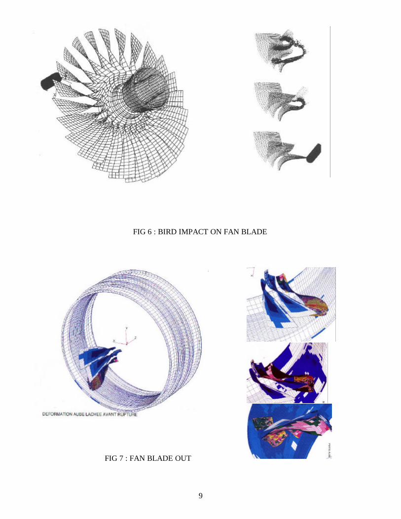
The whole principle of using analysis to simulate the real structural behavior relies ontheoretical methods being available of appropriated effects. Extensive research programs arepursued at SNECMA in association with engineer schools and universities. These programsmove forward theory rapidly, they enable greater understanding of more detailed problems.This will become the underlying theory of to morrow’s software. Some areas of particularinterest concern dynamics simulations on structures, such as impact [Fig 6], bladefragmentation [Fig 7], retention, and vibrations. Not only are the effects of these phenomenadifficult to model but in many case the applied loading environment is also difficult to establish.Others areas which may lead to improved analysis concern the effects of local features such asbolted flanges, contacts [Fig 8], the welded joint, small vent holes in the blade. The ability tointroduce these local effects into a larger analysis would lead to improve the representation ofthe real structure. [Fig 9]
Material data
No important progress in structure analysis will be obtained without a appropriate accuratematerial data knowledge. The characteristics obtained with 1D specimens are generally wellknown. Important research programs are sustained by SNECMA to better represent the 3Dviscoelastoplastic behavior of materials, especially on turbine blade. It is necessary to add indepth studies on damping of materials for dynamic problems, and on rupture criteria forfragmentation, perforation. Finally, we have to make major effort to improve materialproperties in the damage domain, it is necessary to calculate a reliable damage after a finiteelement analysis of a blade during each flight. All these data are coming from tests and it isvery expensive to identify a very important number of laws parameters, this is a restrictivefactor for the precision of the analyses. The decision to use a new material is critical and candrive to limit very strongly the confidence in the analysis.
User environment
In order to effectively use the developing methods, the software and hardware environmentneeds to be able to cope with the demands place on it. Fortunately the performance ofaffordable computers is increasing rapidly, thus the potential to analyze structures of enormouscomplexity, considerably greater today, will be reality in a few years. Techniques ofprogramming object bring also the possibility to have open platforms [Fig 10] [Fig 11].Advanced functionality exist or will be available in a short time especially in PATRAN, toprovide to engineer an information easily accessible, and easily comprehensible. Visualizationssuch that animations in real time are the key of the comprehension of the structure behavior.Automation of the process to built a finite element model, help to put the boundariesconditions, help to analyze results, use more and more of deposit process, and in a close futureuse of knowledge with inference engine will participate in the reduction of errors and time.

5
I t will be possible to simulate more and more in detail complex geometry and complex loadswithout strong hypothesis or approximations. This possibility generates models with numbersof degrees of freedom equal 10^4 to 10^5 and soon more than 10^6. Maintaining thecalculation under control has to be a constant concern of the software vendors , concepts ofadaptive meshing, control of the solutions with errors estimators have to constitute majorevolution of PATRAN. Possibility to create complex models rapidly, to introduce non lineareffects at the level of a small detail will provide a realistic alternative to commonly employedapproximations today The future solutions will be developments of “zoom ” or multi-scale techniques, several details and the global model are analyzed simultaneously, information areexchange in parallel to global and local model frontiers so as to guarantee equilibrium .
Integration of all the tools use in the process is also an essential factor to provide a directaccess at all data in all systems [Fig 12]. It allows assure the optimum flow of information. It isnecessary to notice that the geometric model is the heart of structural analysis activity.
Tools for stress analysis will have to be piloted directly by the system of CAO. In currentenvironment of the SNECMA design office, PATRAN has to continue rapidly its effort to linkCATIA. In addition the possibility to easily exchange with CAO systems, analysis system, preand post processing is also a necessity to facilitate the work with different companies incooperation. This flexibility is also interesting to incorporate new tools. In summary, keyselements of the future environment will be : automation, integration, visualization.
CONCLUSION
They are obvious weaknesses in the ability of analysis to accurately predict all structuralbehavior, It is demonstrated that tests also have deficiencies to represent real life. Thus thecombination of tests and the simulation is the best means to provide a high confidence level ina quick design of complex system. With the likely improvements in calculations capacities, andtheoretical methods, future tools will be increasingly efficient, and will allow to simulatesituations of life in details. These simulations will have to be used intensively in demonstratorsprojects, so as to validate process, new technological systems, upstream of developmentprojects The use of simulation during all along the life of the blade, will allow to improvethem, and to reply as quickly as possible to requests of quality and reliability. Finally, it isnecessary to insist on inter-operability of simulation tools, centered on a numerical geometricalmodel. This inter-operability has to accompany the concept of extended enterprise and theworld cooperation necessity. The keys of the success of industrial products design of the nextcentury.
REFERENCESA.Letellier, Hariddh Bung, Pascal Galon, Marc BerthillierBird impact on fan blade analysis using Smooth Particle Hydrodynamics coupled with FiniteElements. ASME 97 Structure under extreme loading conditions, PVP Vol 351 pages 191-195
Marc Berthillier, Christian Dupont, Philippe Chanez, Frédéric SauratRéponse Forcée aéroélastique des aubes de turbomachines.

6
FIG 1-2: MOTEUR CFM56-7

7
FIG 2: AUBE DE TURBINE MODELEGEOMETRIQUE ET ELEMENTS FINIS
FIG 3 : CATIA and PATRAN MODEL

8
FIG 4 : ISO DISPLACEMENT ON HIGH MODECOMPARISON ANALYSE/ESSAI (HOLOGRAPHIE)
FIG 5: optimization process today
9
FIG 6 : BIRD IMPACT ON FAN BLADE
FIG 7 : FAN BLADE OUT

10
FIG : 8 BLADE/CASING CONTACT SIMULATION
FIG 9 : DAMPING SIMULATION ON BLADE /DISK SYSTEM

11
FIG : 10 OPTIMIZATION FUTURE PLAFORM
FIG : 11 INTER-OPERABILITY CATIA/ PATRAN

12
FIG : 12 INTER-OPERABILITY MODELING/SIMULATION