structural window frame for seismic strengthening of ... · reboco, which is a pre-mixed natural...
TRANSCRIPT

1
Structural window frame for seismic strengthening of masonry wall
buildings André Filipe Vilas Boas
Instituto Superior Técnico, University of Lisbon, Portugal February 2017
Abstract
The present paper reports the development stages of a structural window frame system for in-plane seismic strengthening of load bearing masonry wall buildings.
The strengthening concept is presented based on the observation that the existence of openings in load bearing masonry wall buildings (windows and doors) often leads to the formation of in-plane collapse mechanisms. The solution developed ultimately aims to stiffen (and strengthen) the opening to an extent that the wall behaves as if no opening exists. This aim is achieved by installing a steel profile forming a ring inside the opening, properly tied to the surrounding masonry wall.
The strengthening concept was validated by means of a testing campaign in which two approximately 1:2 geometric scale physical models with a similar central opening were cyclically tested to failure. One of these models (UMW) was unreinforced whereas the other (RMW) had a UPN profile internal ring (working in the weak axis) tied at the corners and at mid-length and mid-height by means of threaded rebars with chemical anchors. The material of these walls was common rubble masonry with lime-based mortar and render. These wall models were subjected to a constant vertical load with a cyclically increasing top lateral (in-plane) displacement history.
The experimental results show that the strengthening technique leads to a significant increase of strength and in-plane deformation capacity as well as in terms of cumulative dissipated energy at collapse.
Non-linear numerical models of the perforated walls were developed and calibrated. Numerical results showed good agreement with the experimental results. Key-words: seismic window frame, seismic reinforcement, stone masonry buildings, non-linear analysis, experimental tests, rehabilitation 1. Introduction
In Portugal, much similarly to other southern European (and earthquake-prone) countries there is a large number of old unreinforced masonry buildings, built before any regulation regarding seismic loads was established. The main structural elements that resist earthquakes in this type of buildings are the unreinforced masonry walls that make up the vertical loadbearing structure which were empirically designed to withstand gravity loads only, making the same buildings seismically vulnerable by today’s standards.
Whereas significant research has been conducted and reported for strengthening of solid masonry walls, much less has been made for retrofitting perforated masonry walls (walls with openings). One of these researches was conducted by Kalali (2012), who evaluated the cyclic behaviour of perforated brick masonry walls strengthened with glass fibre reinforced polymers, analysing the effect of different quantities, types and layouts of the FRP used. The main objective of this study is to evaluate the feasibility of in-plane strengthening of masonry walls with openings through the installation of a structural window frame inside the opening. Thus, in this research, an experimental program was carried out in which two rubble stone masonry walls (one unreinforced and the other reinforced) were cyclically tested to failure. Nonlinear finite element models of both walls were also developed and calibrated using DIANA program with the objective of allowing for parametric studies to be carried out in the future. 2. In-plane collapse mechanisms of masonry walls
Load bearing masonry walls subjected to in-plane loading may have two typical types of behaviour: flexural behaviour and shear behaviour, each one with different failure modes associated. In-plane mechanisms usually are not sufficient to lead to structure collapse.

2
In the first type (shear), the mode of failure depends on the applied level of vertical load. If the applied vertical load is low compared to the compressive strength, the horizontal load produces tensile flexural cracking at the corners and the wall begins to behave as a nearly rigid body rotating around the compressed corner - rocking. In the other hand, if the applied vertical load is sufficiently high, crushing of the masonry located at the compressed corner may occur.
In the second type (flexural), the horizontal load may produce two different modes of failure: the sliding shear failure, in which the development of flexural cracking at the corners under tension reduces the resisting section and failure occurs with sliding on a horizontal bed joint plane; and diagonal cracking, in which failure is attained through the formation of a diagonal crack, which typically develops at the centre of the wall and then propagates towards the corners (POLIMI, 2010).
Figure 2.1 - Typical in-plane failure modes of masonry walls: (a) sliding shear failure; (b) rocking; and (c) diagonal
cracking. (Cakir, 2015)
3. In-plane behaviour of the steel ring
There is no doubt that the existence of openings in loadbearing masonry wall buildings (e.g., windows and doors) can be regarded as sources of fragility for the in-plane behaviour of these walls. Therefore, the strengthening solution under development ultimately aims to stiffen (and strengthen) the opening to an extent that the wall behaves as if no opening exists. In other words, the stiffness of the steel ring provides an additional stiffness (K*) comparable to the stiffness of the diagonal masonry strut of a wall with the same dimensions of the opening (K).
To simulate different connections between the steel ring and the surrounding masonry, three different rectangular frame models were studied: Model A in which the in-plane rotation is released in every node, Model B in which the in-plane rotation is restrained in every node and Model C in which the rotation is released in every node, but restrained at mid-height of the vertical steel profiles.
The masonry strut model adopted and the different steel ring models analysed are presented in Figure 3.1, where b and h correspond to the opening dimensions (width and height, respectively), qi corresponds to the structure’s degrees of freedom, F is the in-plane horizontal force applied on the structure, L is the length of the diagonal masonry strut and a is the angle between the strut and the horizontal. Note that the area of the masonry strut is equal to the product between the thickness (t) and width, which corresponds, approximately, to 15% of the total strut (Fardis, 2005).
Figure 3.1 - Masonry strut model and the different steel ring models analysed
The horizontal stiffness of the masonry strut model can be obtained by Eq.( 3.1 ) and the horizontal stiffness of the different steel ring models analysed can be obtained by Eq.( 3.2 ), Eq.( 3.4 ) and Eq.( 3.6 ), where E"#$%&'( represents the Young’s modulus of the masonry and E$)**+ represents the Young’s modulus of the steel profile. Once these expressions are derived, it is possible to evaluate the minimum required flexural inertia of the steel profiles so that the reinforced perforated wall behaves as if no opening exists. The simplified expressions are presented in Eq.( 3.3 ), Eq.( 3.5 ) and Eq.( 3.7 ).
a
Masonry Strut Model

3
K = E"#$%&'( ⋅ 0.15t ⋅b5
b5 + h5 ( 3.1 )
Model A: K8∗ = E$)**+I24
h5(b + h) ( 3.2 ) I =
E"#$%&'(E$)**+
⋅ 0.15t ⋅b5h5(b + h)24(b5 + h5)
( 3.3 )
Model B: K?∗ = E$)**+I24h@
( 3.4 ) I =E"#$%&'(E$)**+
⋅ 0.15t ⋅b5h@
24(b5 + h5) ( 3.5 )
Model C: KA∗ = E$)**+I192 b + 3hh@(4b + 3h)
( 3.6 ) I =E"#$%&'(E$)**+
⋅ 0.15t ⋅b5h@(4b + 3h)
192 b + 3h (b5 + h5) ( 3.7 )
4. Characterization of masonry materials
Two identical perforated rubble stone masonry walls were built to assess their behaviour under static cyclic shear tests (Figure 4.1). Both walls were constructed over a 2.3 x 1.0 x 0.3 (m) reinforced concrete footing, the outside dimensions of the walls were 2.1 x 0.3 x 1.5 (m) and the openings’ dimensions, centred on the wall, were 0.5 x 0.3 x 0.75 (m).
The geometric scale physical models were made with Lioz stone, a type of limestone largely used in the past in Portugal as an ornamental rock or as a structural material. The mortar chosen was REABILITA CAL Reboco, which is a pre-mixed natural hydraulic lime mortar produced by Secil Argamassas. This product belongs to the class CSII according to the European standard EN 998-1 and has a compressive strength varying between 1.5 and 5.0 MPa (MPA, 2015). As a reference, Cunha (2013) determined that the compressive strength and flexural strength of REABILITA CAL Reboco were 1.70 MPa and 1.00 MPa, respectively. To satisfy the requirement of having a mortar as consistent as possible with that of historical buildings, this resistance was reduced by adding 5 kg of sand for every 25 kg of mortar.
According to the EN 1015-11 standard (CEN, 1999), six prismatic specimens (160 x 40 x 40 (mm)) of the weakened hydraulic mortar were tested. The average obtained value of the flexural strength (mortar tensile strength obtained by bending tests) was 0.24 MPa and the average value obtained of the compressive strength, which was determined through compression tests performed on the half-prims that resulted from the bending tests, was 0.50 MPa.
Figure 4.1 - Geometry of the masonry walls built (m)
5. Characterization of the strengthening solution
Model C is naturally the one that most restrains the movements of the steel ring. As predicted, the minimum required inertia of the steel profiles obtained by the simplified design expressions presented in 3 was 36.72cmI (Model C). Therefore, the idealized strengthening solution consists of a UPN160 profile internal ring (working in the weak axis - inertia of 85.3cmI) tied at the corners and at mid-length and mid-height by means of threaded rebars, which were fixed to the surrounding masonry with chemical anchors, as can be observed in Figure 2.1.
Since the wall models were built in a controlled environment, it is possible to ensure that there are no large voids inside the masonry, and for this reason, the use of sleeves for the threaded rebars can be avoided. The exemption of use of sleeves requires a higher effective embedment depth of the threaded rebars into the chemical, of around 200 mm. The adopted injection system was HIT-HY 270, a high performance chemical anchor suitable for the most common types of masonry materials and produced by HILTI. The working time of
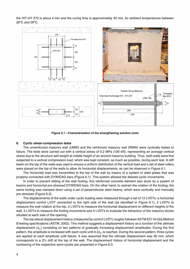
4
the HIT-HY 270 is about 4 min and the curing time is approximately 30 min, for ambient temperatures between 20ºC and 29ºC.
Figure 5.1 - Characterization of the strengthening solution (mm)
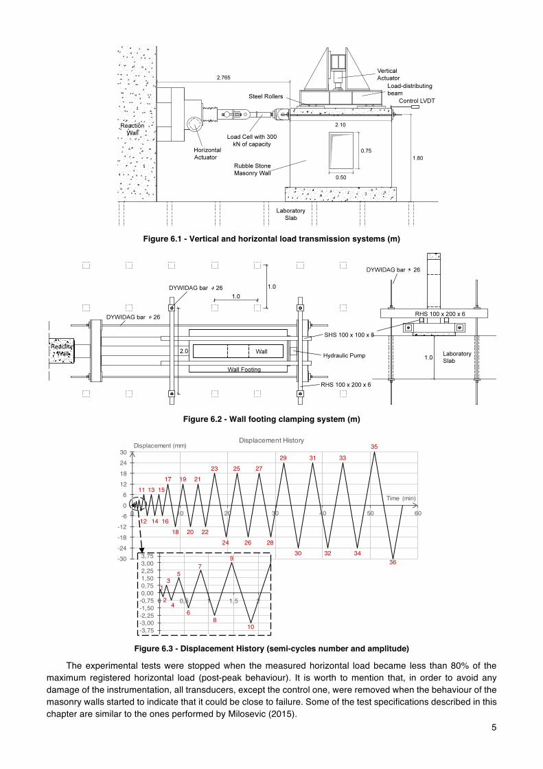
6. Cyclic shear-compression tests
The unreinforced masonry wall (UMW) and the reinforced masonry wall (RMW) were cyclically tested to failure. The tests were carried out with a vertical stress of 0.2 MPa (126 kN), representing an average vertical stress due to the structure self-weight at middle height of an ancient masonry building. Thus, both walls were first subjected to a vertical compression load, which was kept constant, as much as possible, during each test. A stiff beam on the top of the walls was used to ensure a uniform distribution of the vertical load and a set of steel rollers were placed on the top of the walls to allow its horizontal displacements, as can be observed in Figure 6.1. The horizontal load was transmitted to the top of the wall by means of a system of steel plates that was properly connected with DYWIDAG bars (Figure 6.1). This system allowed the desired cyclic movements. In order to prevent sliding of the wall footing, this reinforced concrete element was stuck by a system of beams and horizontal pre-stressed DYWIDAG bars. On the other hand, to restrain the rotation of the footing, the same footing was clamped down using a set of perpendicular steel beams, which were vertically and manually pre-stressed (Figure 6.2). The displacements of the walls under cyclic loading were measured through a set of 12 LVDTs: a horizontal displacement control LVDT connected to the right side of the wall (as identified in Figure 6.1), 2 LVDTs to measure the wall rotation at the top, 2 LVDTs to measure the horizontal displacement on different heights of the wall, 3 LVDTs to measure the footing movements and 4 LVDTs to evaluate the behaviour of the masonry blocks situated at each side of the opening.
The top lateral displacement history (measured by control LVDT) roughly followed ASTM E2116-02a Method B testing specifications (ASTM, 2002). This method suggests a displacement history as a function of the ultimate displacement (∆L) consisting on two patterns of gradually increasing displacement amplitudes. During the first pattern, the amplitude is increased with each cycle until 0.2∆L is reached. During the second pattern, three cycles are applied at each amplitude until failure. It was assumed that the ultimate displacement was 30 mm, which corresponds to a 2% drift at the top of the wall. The displacement history of horizontal displacement and the numbering of the respective semi-cycles are presented in Figure 6.3.
5
Figure 6.1 - Vertical and horizontal load transmission systems (m)
Figure 6.2 - Wall footing clamping system (m)
Figure 6.3 - Displacement History (semi-cycles number and amplitude)
The experimental tests were stopped when the measured horizontal load became less than 80% of the maximum registered horizontal load (post-peak behaviour). It is worth to mention that, in order to avoid any damage of the instrumentation, all transducers, except the control one, were removed when the behaviour of the masonry walls started to indicate that it could be close to failure. Some of the test specifications described in this chapter are similar to the ones performed by Milosevic (2015).
11
12
13
14
15
16
17
18
19
20
21
22
23
24
25
26
27
28
29
30
31
32
33
34
35
36-30 -24 -18 -12
-6 06
12182430
0 10 20 30 40 50 60
Displacement (mm)
Time (min)
Displacement History
1
2
3
4
5
6
7
8
9
10
-4,50 -3,75 -3,00 -2,25 -1,50 -0,75 0,000,751,502,253,003,754,50
0 0,5 1 1,5 2 2,5

6
7. Experimental results 7.1 Typical behaviour and failure modes 7.1.1 Unreinforced masonry wall (UMW)
At displacements of around 6 mm, the first diagonal crack due to the shear mechanism appeared at the centre of both masonry blocks. As the lateral force increased, the opening of these cracks reached larger values and the cracks propagated towards the upper and bottom corners of the wall and towards the upper and bottom corners of the opening.
The cyclic test of the unreinforced masonry wall ended when a +24 mm of horizontal displacement on the top of the wall (semi-cycle 29) was reached, for the first time. The failure of the UMW was attributed to diagonal cracking in both masonry blocks, which occurred along the stone-mortar interface. The crack pattern and the damage state of the UMW for a lateral displacement of -18 mm can be seen in Figure 7.1.
Figure 7.1 - Crack pattern and the damage state of the UMW for a lateral displacement of -18 mm
7.1.2 Reinforced masonry wall (RMW)
As happened in the UMW, the first diagonal crack appeared at the centre of both masonry blocks at displacements of around 6 mm. With increasing imposed displacements, the process of forming new cracks and extending the existing ones continued.
The cyclic test of the reinforced masonry wall ended when a -30 mm of horizontal displacement on the top of the wall (semi-cycle 36) was reached for the first time. The failure of the UMW was predominantly influenced by diagonal cracking in both masonry blocks, although some rotation on the top of the wall and significant horizontal cracks were noticed, two features usually attributed to rocking failure.
The installation of the UPN160 steel ring inside the opening and the way it was tied to the surrounding masonry clearly influenced the crack pattern and the collapse mechanism. It is worth to mention that the inferior horizontal steel profile had its screws loose at the end of the test (evidence of strong tensile forces at that region) as well as horizontal sliding of this steel profile was noticed (evidence of strong shear forces at steel-masonry interface). The crack pattern of the RMW and deformation of the strengthening solution for a lateral displacement of +18 mm can be seen in Figure 7.2.
After the tests, some stone units, which seemed to be still part of the walls, were in fact detached from it and could be removed by hand. Also, a significantly part of the render layer had detached from the masonry during the tests and fell to the floor.
Figure 7.2 - Crack pattern of the RMW and deformation of the strengthening solution for a lateral displacement of
+18 mm

7
7.2 Typical hysteresis diagrams In addition to the crack patterns and failure modes, the horizontal force - horizontal displacement diagrams
provide valuable information on the lateral in-plane behaviour, needed to evaluate the seismic performance. For the UMW, on the positive side of the curve the maximum applied load was +70.41 kN, at a horizontal
displacement of +12 mm. For the negative side of the curve, the maximum applied load was -71.59 kN, at a horizontal displacement of -6 mm. The cyclic response of this wall showed some asymmetry, namely at the level of the maximum lateral strength observed.
In the case of the RMW, on the positive side of the curve the maximum applied load was +104.46 kN, at a horizontal displacement of +12 mm. For the negative side of the curve, the maximum applied load was -94.14 kN, at a horizontal displacement of -12 mm.
Comparing the behaviour of both walls, UMW showed less deformation capacity and less horizontal in-plane resistance than RMW. The improvements in terms of resistance were around 48% for the positive side of the curve and 32% for the negative side if the curve. The UMW and RMW horizontal force vs. horizontal displacement hysteresis diagrams are presented in Figure 7.3.
Figure 7.3 - Horizontal force vs. control displacement hysteresis diagrams
7.3 Energy Dissipation
The energy dissipated at each nonlinear loading cycle is obtained by calculating the area enclosed by the loop in the load-displacement diagram. The dissipated energy is associated with the propagation of damage trough the wall (crack opening) and with the increase of the lateral displacement, which leads to a higher area inside the hysteresis loop. The evolution of the dissipated energy until failure of the two walls tested is presented in Figure 7.4. The total dissipated energy by UMW was 8568.85 J and the total dissipated energy by RMW was 21167.02 J, which means an increase of 147.0% of wall capacity to dissipate energy when strengthened with the structural window frame. Until semi-cycle 16, both walls dissipated the same amount of energy. After this stage, the RMW managed to dissipate more energy and the difference between UMW and RMW in terms of dissipated energy increased until failure.
Figure 7.4 - Cumulative Dissipated Energy for both specimens
-120
-100
-80
-60
-40
-20
0
20
40
60
80
100
120
-36 -30 -24 -18 -12 -6 0 6 12 18 24 30 36
Horizontal Force (kN)
Displacement (mm)
Horizontal Force - Control Displacement (UMW)
-120 -100 -80 -60 -40 -20
020406080
100120
-36 -30 -24 -18 -12 -6 0 6 12 18 24 30 36
Horizontal Force (kN)
Displacement (mm)
Horizontal Force - Control Displacement (RMW)
02468
10121416182022
0 2 4 6 8 10 12 14 16 18 20 22 24 26 28 30 32 34 36 38
Energy (kJ)
Milhares
Semi-cycle
Cumulative Dissipated Energy
RMWUMW

8
8. Numerical analysis Finite element models of the perforated walls were developed using the DIANA 9.2 software to simulate the
response of the tested masonry walls under in-plane loading. The calibration of the materials’ behaviour to tensile and compression forces as well as the calibration of the materials’ proprieties will allow, in the future, the assessment of different steel window frame solutions. 8.1 Numerical modelling of the unreinforced masonry wall (UMW) 8.1.1 Numerical model
Reinforced Concrete was modelled as a linear isotropic elastic material with a Young’s modulus of 30 GPa, a Poisson ration of 0.2 and a density of 25.0 kN/m3.
Rubble stone masonry was described using a macro-modelling approach, in which the masonry is treated as a composite, homogeneous and isotropic material. This approach is more suitable for the study of old and irregular masonry walls with multiple leafs. Thus, the constitutive model adopted was the Total Strain Rotating Crack Model (RCM), which describes the tensile and compressive behaviour of a material with one stress-strain relationship and is well suited for analyses predominantly governed by cracking or crushing of the material (TNO DIANA, 2007). The RCM allows a gradual correction of the initially crack direction as the crack plane can rotate during the analysis. Linear elastic and exponential stress-strain relations were used to describe the tensile and compressive behaviour of the masonry respectively (see Figure 8.2) to avoid local crushing of the masonry, since only shear and tensile events were observed during the experimental tests. A regular mesh discretization (see Figure 8.1) was developed using eight-node quadrilateral isoparametric plane stress elements (50 x 75 mm) based on quadratic interpolation and Gauss integration - CQ16M. The pre-compression level of 0.2 MPa was distributed through a set of nodes located at the top of the wall, accordingly to the experimental setup. The horizontal load was applied to the concrete beam (nodes 2876, 2829 and 2853) and the displacement was measured at the top of the same beam (node 3040). In order to block the footing movements, all degrees of freedom of the nodes on the base were restrained: translation in x, translation in y and rotation in z. Concrete and masonry self-weight was also considered.
Figure 8.1 - Generated mesh and CQ16M element Figure 8.2 - Tensile and compressive
behaviour of the masonry
8.1.2 Calibration and analysis After the model definition was completed, a physical nonlinear monotonic analysis was performed to
evaluate the in-plane behaviour of the unreinforced masonry wall. The Quasi-Newton (Secant) BFGS iterative method was used with an internal energy convergence tolerance of 10-3. The experimental envelope as well as the obtained numerical curve after an iterative calibration process of some masonry proprieties can be seen in Figure 8.3. It is worth to mention that DIANA 9.2 only provides the positive branch of the numerical curve, which was mirrored to the negative side to help in the calibration process. Table 8.1 summarizes the calibrated masonry proprieties. Note that the Young’s modulus obtained (800 MPa) is in accordance with the work carried out by Araújo (2014), in which a similar rubble stone masonry wall with hydraulic lime based mortar was numerically cyclically tested to failure (with identical pre-compression level). On the other hand, the tensile strength achieved (0.02 MPa) is much higher than the average resistance values obtained for this type of masonry, see Milosevic (2013) and Magenes (2010). Actually, the tensile strength achieved matches the typical known values for masonry with aerial lime based mortars, e.g. 0.024 MPa obtained by Milosevic (2013).

9
Table 8.1 - Calibrated masonry proprieties
Masonry E (GPa) Poisson Ratio Density
(kN/m3) Tensile Strength
(MPa) Tensile Fracture Energy
(Nmm/mm2) 0.800 0.2 18.35 0.02 0.02
Figure 8.3 - Experimental envelope and calibrated numerical curve (UMW)
The analysis results of the UMW showed that the in-plane behaviour of this wall is in agreement with the experimental monotonic envelope as the maximum capacity is well estimated (76.59 kN for a top lateral displacement of 5.67 mm) and the non-linear behaviour fits with very good approximation the experimental curve. The damage pattern was also evaluated for UMW analysis by plotting the maximum principle strains distribution at failure (see Figure 8.4). The crack pattern resultant from the experimental testing of this wall presented cracking through the two block diagonals, consistent with the damage found in this analysis results, which evidences a clear shear failure by diagonal cracking. The UMW deformation state at collapse can be seen in Figure 8.5.
Figure 8.4 - Damage pattern at failure (UMW) Figure 8.5 - Deformation state at failure (UMW)
8.2 Numerical modelling of the reinforced masonry wall (RMW)
In this section, the aim is to add the strengthening solution to the numerical model of the UMW developed and calibrated in 8.1. Steel forming the metal profile was modelled as a linear isotropic elastic material with a Young’s modulus of 210 GPa, a Poisson ration of 0.3 and a density of 78.6 kN/m3. UPN 160 steel profile was described using a two-node, two-dimensional beam element, L7BEN, and a predefined U-shape was used (TNO DIANA, 2007). In addition, a frame constituted by linear elastic elements was created around the opening in order to improve convergence.
A physical nonlinear monotonic analysis was performed to evaluate the in-plane behaviour of the reinforced model. The resultant numerical curve showed better approximation with the experimental hysteresis curve when the steel frame was numerically tied to the surrounding masonry only at the compressive nodes (both mentioned curves can be seen in Figure 8.6). The maximum horizontal force estimated was 105.8 kN and occurred for a top horizontal displacement of 8.98 mm.
-100
-80
-60
-40
-20
0
20
40
60
80
100
-24 -18 -12 -6 0 6 12 18 24 30
Horizontal Force (kN)
Displacement (mm)
Horizontal Force - Control Displacement (UMW)
Experimental Envelope
Numerical curve

10
Figure 8.6 - Experimental curve and calibrated numerical curve (RMW)
8.3 Numerical modelling of the solid wall (without opening)
A numerical model of a solid wall equivalent to the unreinforced model, but without the central opening, without the concrete lintel and with the vertical pre-compression level of 0.2 MPa uniformly distributed by the entire wall section was created and numerically tested. The resultant numerical curve can be seen in Figure 8.7 and is characterized by a maximum horizontal force of 117.5 kN. Comparing all numerical curves (UMW, RMW and solid wall), it is possible to conclude that both masonry walls with opening are more flexible than the equivalent solid wall, as expected, and that the solid wall presented more in-plane resistance than perforated walls.
Figure 8.7 - Numerical curve of the solid wall
9. Conclusions The unreinforced masonry wall developed a typical shear mechanism with evident diagonal cracking at the
masonry blocks next to the opening, whereas the reinforced masonry wall developed a mixed shear-rocking mechanism with a more distributed crack pattern.
Although the testing campaign was relatively short, it is possible to conclude that the structural window frame is feasible, since the experimental results showed significant improvements in terms of resistance, deformation capacity and energy dissipation when the strengthening solution is installed inside the masonry wall opening.
The experimental results showed that the strengthening technique led to an increase of around 40% in terms of peak strength capacity and to an increase of 147% in terms of cumulative energy dissipated at collapse.
It should be guaranteed that the steel frame is properly tied to the surrounding masonry. Decreasing the spacing of these ties is shown to significantly decrease the required dimensions of the steel profile.
The numerical results showed good approximation with the experimental results and allowed the calibration of some masonry proprieties. The calibrated model was used to evaluate the in-plane behaviour of an equivalent solid wall, which results were used to measure the extent of the strengthening solution. In terms of in-plane resistance, the real UMW had 71.6 kN as maximum horizontal force, the real RMW had 104.5 kN as maximum horizontal force and the solid wall numerical model had 117.5 kN as maximum horizontal force.
-120
-80
-40
0
40
80
120
-36 -30 -24 -18 -12 -6 0 6 12 18 24 30 36
Horizontal Force (kN)
Displacement (mm)
Horizontal Force - Control Displacement (RMW)
Experimental Envelope
Numerical curve
0
20
40
60
80
100
120
140
0 2 4 6 8 10 12 14 16 18
Horizontal Force (kN)
Displacement (mm)
Horizontal Force - Control Displacement (solid wall)
11
References Araújo, A. (2014). Modelling of the Seismic Performance of Connections and Walls in Ancient Masonry
Buildings. University of Minho, Portugal: Phd Thesis. ASTM. (2002). Standard Test Methods for Cyclic (Reversed) Load Test for Shear Resistance of Walls for
Buildings. USA. Cakir, F., Uçkan, E., Seker, B., & Akbas, B. (2015). Seismic damage evaluation of historical structures during
Van earthquake. Engineering Failure Analysis, 58, 249–266. CEN. (1999). Methods of test for mortar for masonry - Part 11: Determination of flexural and compressive
strength of hardened mortar (EN 1015-11). Brussels: European Committee for Standardization. Cunha, D. (2013). Estudo de argamassas com base em cal hidráulica e suas aplicações. Aveiro: Universidade
de Aveiro: Dissertação de Mestrado. Fardis, M. N. (2005). Designers' guide to EN 1998-1 and EN 1998-5 Eurocode 8 : design of structures for
earthquake resistance : general rules, seismic actions, design rules for buildings, foundations and retaining structures. London: Thomas Telford.
Kalali, A., & Kabir, M. (2012). Cyclic behavior of perforated masonry walls strengthened with glass fiber reinforced polymers. Scientia Iranica, 19, 151-165.
Magenes, G., Penna, A., Galasco, A., & Rota, M. (2010). Experimental Characterisation of Stone Masonry Mechanical Properties. Dresden: 8th International Masonry Conference 2010 in Dresden.
Milosevic, J., Gago, A., Lopes, M., & Bento, R. (2013). Experimental assessment of shear strength parameters on rubble stone masonry specimens. Construction and Building Materials, 47, 1372-1380.
Milosevic, J., Gago, A., Lopes, M., & Bento, R. (2015). In-plane seismic response of rubble stone masonry specimens by means of static cyclic tests. Construction and Building Materials, 82, 9-19.
MPA. (2015). Data sheet 19 - A guide to BS EN 998-1 and BS EN 998-2. London: Mineral Products Association.
POLIMI. (2010). Inventory of earthquake-induced failure mechanisms related to construction types, structural elements, and materials. In New integrated knowledge based approaches to the protection of cultural heritage from earthquake-induced risk. Università di Padova, Italy.
TNO DIANA. (2007). User's Manual - Release 9.2.